EP2964450B1 - Additive manufacturing method for printing three-dimensional parts with purge towers - Google Patents
Additive manufacturing method for printing three-dimensional parts with purge towers Download PDFInfo
- Publication number
- EP2964450B1 EP2964450B1 EP14760240.3A EP14760240A EP2964450B1 EP 2964450 B1 EP2964450 B1 EP 2964450B1 EP 14760240 A EP14760240 A EP 14760240A EP 2964450 B1 EP2964450 B1 EP 2964450B1
- Authority
- EP
- European Patent Office
- Prior art keywords
- layer
- printing
- purge
- print head
- purge tower
- Prior art date
- Legal status (The legal status is an assumption and is not a legal conclusion. Google has not performed a legal analysis and makes no representation as to the accuracy of the status listed.)
- Active
Links
- 238000010926 purge Methods 0.000 title claims description 183
- 238000004519 manufacturing process Methods 0.000 title claims description 35
- 239000000654 additive Substances 0.000 title claims description 32
- 230000000996 additive effect Effects 0.000 title claims description 32
- 239000000463 material Substances 0.000 claims description 129
- 238000000034 method Methods 0.000 claims description 47
- 238000001125 extrusion Methods 0.000 claims description 10
- 230000008859 change Effects 0.000 claims description 3
- 238000010438 heat treatment Methods 0.000 claims description 2
- 239000010410 layer Substances 0.000 description 187
- 239000000758 substrate Substances 0.000 description 31
- 238000000151 deposition Methods 0.000 description 16
- 238000000429 assembly Methods 0.000 description 14
- 230000000712 assembly Effects 0.000 description 14
- 239000002356 single layer Substances 0.000 description 14
- 230000008021 deposition Effects 0.000 description 13
- 230000006870 function Effects 0.000 description 11
- 230000008569 process Effects 0.000 description 7
- 230000009286 beneficial effect Effects 0.000 description 4
- 230000007246 mechanism Effects 0.000 description 4
- 238000004891 communication Methods 0.000 description 3
- 238000010276 construction Methods 0.000 description 2
- 239000007789 gas Substances 0.000 description 2
- 230000008018 melting Effects 0.000 description 2
- 238000002844 melting Methods 0.000 description 2
- 239000012768 molten material Substances 0.000 description 2
- 230000000717 retained effect Effects 0.000 description 2
- 239000004642 Polyimide Substances 0.000 description 1
- 239000011230 binding agent Substances 0.000 description 1
- 239000003054 catalyst Substances 0.000 description 1
- 238000013500 data storage Methods 0.000 description 1
- 230000000593 degrading effect Effects 0.000 description 1
- 230000001934 delay Effects 0.000 description 1
- 238000010894 electron beam technology Methods 0.000 description 1
- 230000009969 flowable effect Effects 0.000 description 1
- 238000005259 measurement Methods 0.000 description 1
- 239000000155 melt Substances 0.000 description 1
- 230000005499 meniscus Effects 0.000 description 1
- 239000000203 mixture Substances 0.000 description 1
- 230000003287 optical effect Effects 0.000 description 1
- 239000004033 plastic Substances 0.000 description 1
- 229920003223 poly(pyromellitimide-1,4-diphenyl ether) Polymers 0.000 description 1
- 229920001721 polyimide Polymers 0.000 description 1
- 238000012805 post-processing Methods 0.000 description 1
- 239000000843 powder Substances 0.000 description 1
- 238000007781 pre-processing Methods 0.000 description 1
- 238000000110 selective laser sintering Methods 0.000 description 1
- 239000007858 starting material Substances 0.000 description 1
- 239000002699 waste material Substances 0.000 description 1
Images


Classifications
-
- B—PERFORMING OPERATIONS; TRANSPORTING
- B29—WORKING OF PLASTICS; WORKING OF SUBSTANCES IN A PLASTIC STATE IN GENERAL
- B29C—SHAPING OR JOINING OF PLASTICS; SHAPING OF MATERIAL IN A PLASTIC STATE, NOT OTHERWISE PROVIDED FOR; AFTER-TREATMENT OF THE SHAPED PRODUCTS, e.g. REPAIRING
- B29C64/00—Additive manufacturing, i.e. manufacturing of three-dimensional [3D] objects by additive deposition, additive agglomeration or additive layering, e.g. by 3D printing, stereolithography or selective laser sintering
- B29C64/30—Auxiliary operations or equipment
- B29C64/35—Cleaning
-
- B—PERFORMING OPERATIONS; TRANSPORTING
- B29—WORKING OF PLASTICS; WORKING OF SUBSTANCES IN A PLASTIC STATE IN GENERAL
- B29C—SHAPING OR JOINING OF PLASTICS; SHAPING OF MATERIAL IN A PLASTIC STATE, NOT OTHERWISE PROVIDED FOR; AFTER-TREATMENT OF THE SHAPED PRODUCTS, e.g. REPAIRING
- B29C64/00—Additive manufacturing, i.e. manufacturing of three-dimensional [3D] objects by additive deposition, additive agglomeration or additive layering, e.g. by 3D printing, stereolithography or selective laser sintering
- B29C64/10—Processes of additive manufacturing
- B29C64/106—Processes of additive manufacturing using only liquids or viscous materials, e.g. depositing a continuous bead of viscous material
- B29C64/118—Processes of additive manufacturing using only liquids or viscous materials, e.g. depositing a continuous bead of viscous material using filamentary material being melted, e.g. fused deposition modelling [FDM]
-
- B—PERFORMING OPERATIONS; TRANSPORTING
- B29—WORKING OF PLASTICS; WORKING OF SUBSTANCES IN A PLASTIC STATE IN GENERAL
- B29C—SHAPING OR JOINING OF PLASTICS; SHAPING OF MATERIAL IN A PLASTIC STATE, NOT OTHERWISE PROVIDED FOR; AFTER-TREATMENT OF THE SHAPED PRODUCTS, e.g. REPAIRING
- B29C64/00—Additive manufacturing, i.e. manufacturing of three-dimensional [3D] objects by additive deposition, additive agglomeration or additive layering, e.g. by 3D printing, stereolithography or selective laser sintering
- B29C64/10—Processes of additive manufacturing
- B29C64/165—Processes of additive manufacturing using a combination of solid and fluid materials, e.g. a powder selectively bound by a liquid binder, catalyst, inhibitor or energy absorber
-
- B—PERFORMING OPERATIONS; TRANSPORTING
- B29—WORKING OF PLASTICS; WORKING OF SUBSTANCES IN A PLASTIC STATE IN GENERAL
- B29C—SHAPING OR JOINING OF PLASTICS; SHAPING OF MATERIAL IN A PLASTIC STATE, NOT OTHERWISE PROVIDED FOR; AFTER-TREATMENT OF THE SHAPED PRODUCTS, e.g. REPAIRING
- B29C64/00—Additive manufacturing, i.e. manufacturing of three-dimensional [3D] objects by additive deposition, additive agglomeration or additive layering, e.g. by 3D printing, stereolithography or selective laser sintering
- B29C64/30—Auxiliary operations or equipment
- B29C64/357—Recycling
-
- B—PERFORMING OPERATIONS; TRANSPORTING
- B29—WORKING OF PLASTICS; WORKING OF SUBSTANCES IN A PLASTIC STATE IN GENERAL
- B29C—SHAPING OR JOINING OF PLASTICS; SHAPING OF MATERIAL IN A PLASTIC STATE, NOT OTHERWISE PROVIDED FOR; AFTER-TREATMENT OF THE SHAPED PRODUCTS, e.g. REPAIRING
- B29C64/00—Additive manufacturing, i.e. manufacturing of three-dimensional [3D] objects by additive deposition, additive agglomeration or additive layering, e.g. by 3D printing, stereolithography or selective laser sintering
- B29C64/30—Auxiliary operations or equipment
- B29C64/386—Data acquisition or data processing for additive manufacturing
- B29C64/393—Data acquisition or data processing for additive manufacturing for controlling or regulating additive manufacturing processes
-
- B—PERFORMING OPERATIONS; TRANSPORTING
- B33—ADDITIVE MANUFACTURING TECHNOLOGY
- B33Y—ADDITIVE MANUFACTURING, i.e. MANUFACTURING OF THREE-DIMENSIONAL [3-D] OBJECTS BY ADDITIVE DEPOSITION, ADDITIVE AGGLOMERATION OR ADDITIVE LAYERING, e.g. BY 3-D PRINTING, STEREOLITHOGRAPHY OR SELECTIVE LASER SINTERING
- B33Y10/00—Processes of additive manufacturing
-
- B—PERFORMING OPERATIONS; TRANSPORTING
- B33—ADDITIVE MANUFACTURING TECHNOLOGY
- B33Y—ADDITIVE MANUFACTURING, i.e. MANUFACTURING OF THREE-DIMENSIONAL [3-D] OBJECTS BY ADDITIVE DEPOSITION, ADDITIVE AGGLOMERATION OR ADDITIVE LAYERING, e.g. BY 3-D PRINTING, STEREOLITHOGRAPHY OR SELECTIVE LASER SINTERING
- B33Y50/00—Data acquisition or data processing for additive manufacturing
- B33Y50/02—Data acquisition or data processing for additive manufacturing for controlling or regulating additive manufacturing processes
Definitions
- the present disclosure relates to additive manufacturing systems for printing or otherwise building three-dimensional (3D) parts with layer-based, additive manufacturing techniques.
- the present disclosure relates to purge operation techniques for use in extrusion-based additive manufacturing systems.
- Additive manufacturing systems are used to print or otherwise build 3D parts from digital representations of the 3D parts (e.g., AMF and STL format files) using one or more additive manufacturing techniques.
- additive manufacturing techniques include extrusion-based techniques, jetting, selective laser sintering, powder/binder jetting, electron-beam melting, and stereolithographic processes.
- the digital representation of the 3D part is initially sliced into multiple horizontal layers.
- a tool path is then generated, which provides instructions for the particular additive manufacturing system to print the given layer.
- a 3D part may be printed from a digital representation of the 3D part in a layer-by-layer manner by extruding a flowable part material.
- the part material is extruded through an extrusion tip or nozzle carried by a print head of the system, and is deposited as a sequence of roads on a substrate in an x-y plane.
- the extruded part material fuses to previously deposited part material, and solidifies upon a drop in temperature.
- the position of the print head relative to the substrate is then incremented along a z-axis (perpendicular to the x-y plane), and the process is then repeated to form a 3D part resembling the digital representation.
- supporting layers or structures are typically built underneath overhanging portions or in cavities of 3D parts under construction, which are not supported by the part material itself.
- a support structure may be built utilizing the same deposition techniques by which the part material is deposited.
- the host computer generates additional geometry acting as a support structure for the overhanging or free-space segments of the 3D part being formed.
- Support material is then deposited from a second nozzle pursuant to the generated geometry during the printing process. The support material adheres to the part material during fabrication, and is removable from the completed 3D part when the printing process is complete.
- An aspect of the present disclosure is directed to a method for printing a 3D part with an additive manufacturing system according to claim 1.
- the method includes printing layers of the 3D part and of a support structure for the 3D part from multiple print heads using an extrusion-based, additive manufacturing technique, and switching the print heads between stand-by modes and operating modes in-between the printing of the layers of the 3D part and the support structure.
- the method also includes performing a purge operation for each print head switched to the operating mode, where the purge operation includes printing a layer of at least one purge tower from the print head switched to the operating mode.
- Another aspect of the present disclosure is directed to a method for printing a 3D part with an additive manufacturing system, which includes bringing a first print head or deposition line from a stand-by mode to an operating mode, printing a first layer of a purge tower from a support material using the first print head or deposition line in the operating mode, and printing a layer of a support structure from the support material using the first print head in the operating mode after printing the first layer of the purge tower.
- the method also includes bringing a second print head or deposition line from a stand-by mode to an operating mode, printing a second layer of the purge tower from a part material using the second print head or deposition line in the operating mode, and printing a layer of the 3D part from the part material using the second print head in the operating mode after printing the second layer of the purge tower.
- Another aspect of the present disclosure is directed to a method for printing a 3D part with an additive manufacturing system, which includes printing a first layer of a support structure for the 3D part, printing a first layer of a purge tower from a part material, and printing a first layer of the 3D part on at least a portion of the first layer of the support structure from the part material after printing the first layer of the purge tower.
- the method also includes printing a second layer of the purge tower from the support material, and printing a second layer of the support structure on at least a portion of the first layer of the 3D part from the support structure after printing the second layer of the purge tower.
- Directional orientations such as “above”, “below”, “top”, “bottom”, and the like are made with reference to a layer-printing direction of a 3D part.
- the layer-printing direction is the upward direction along the vertical z-axis.
- the terms “above”, “below”, “top”, “bottom”, and the like are based on the vertical z-axis.
- the terms “above”, “below”, “top”, “bottom”, and the like are relative to the given axis.
- providing such as for “providing a print head”, when recited in the claims, is not intended to require any particular delivery or receipt of the provided item. Rather, the term “providing” is merely used to recite items that will be referred to in subsequent elements of the claim(s), for purposes of clarity and ease of readability.
- the present disclosure is directed to a method for printing 3D parts and support structures using an additive manufacturing system with the use of a purge tower (or multiple purge towers).
- a purge tower or multiple purge towers.
- one or more support structures may be built underneath overhanging portions or in cavities of 3D parts under construction, which are not supported by the part material itself.
- the support structures are preferably printed from a support material that is removable from the associated 3D part after the printing operation is completed.
- the additive manufacturing system may utilize multiple print heads or deposition lines, where a first print head or deposition line may be used to print the 3D part, and a second material print head or deposition line may be used to print the support structure.
- a first print head or deposition line may be used to print the 3D part
- a second material print head or deposition line may be used to print the support structure.
- the following disclosure is made with reference to separate print heads for printing 3D parts and support structures, referred to as a "part print head” and a "support print head”.
- Examples of such part and support print heads include those disclosed in Swanson et al., U.S. Publication Nos. 2010/0283172 and 2012/0164256 .
- the method of the present disclosure is equally applicable for use with a single deposition head having multiple deposition lines for printing 3D parts and support structures. Examples of such deposition heads include those disclosed in Leavitt, U.S. Patent No. 7,625,200 , and LaBossiere et al.
- each print head or deposition line is switchable between an "operating mode” and a "stand-by mode".
- the operating mode is preferably a mode in which a liquefier assembly of the print head to be heated to its set point operating temperature(s) to generate a desired thermal gradient for melting the part or support material.
- the stand-by mode is preferably a mode in which the liquefier assembly of the print head is cooled down from its operating mode to prevent its part or support material from thermally degrading, oozing or dripping out.
- one or more of the print heads when switching between the operating mode and the stand-by mode, are lifted, pivoted, or otherwise moved relative to the build plane and/or each other, such as also disclosed in Leavitt, U.S. Patent No. 7,625,200 , LaBossiere et al., U.S. Patent No. 7,604,470 , and Swanson et al., U.S. Publication Nos. 2010/0283172 and 2012/0164256 .
- a print head when switching from the operating mode to the stand-by mode, may be lifted, pivoted, or otherwise moved away from the build plane by a small distance to prevent interference with the printed layers. Then, when subsequently switched back to its operating mode, the print head moved back to its original distance relative to the build plane for printing a subsequent layer.
- the support print head is its stand-by mode, and vice versa.
- the additive manufacturing system may then switch the print heads such that the support print head is brought to its operating mode to print a layer of the support structure, and the part print head is brought to its stand-by mode. Then, after the support structure layer is completed, the additive manufacturing system may switch the print heads back such that the part print head is brought to its operating mode to print a layer of the support structure, and the part print head is brought to its stand-by mode.
- each print head When each print head is brought to its operating mode, it undergoes a purge operation prior to printing the next layer.
- a purge operation conventionally involves moving the given print head to a purge station, where it extrudes a strand of the part or support material into a purge bucket, optionally followed by a tip wipe operation.
- Performing purge operations and creating blocks of waste material during layer-wise manufacturing is furthermore also known from WO2012085914A1 .
- This purge operation provides several desired functions. First, it frees any part or support material filament that may be adhered to the walls of the liquefier assembly, and verifies that the print head can extrude the part or support material. It also removes any entrained gases and degraded materials in the print head, and brings the print head to a known operating state for printing the subsequent layer, such as bringing a meniscus in the liquefier assembly to a substantially known position and raising the internal temperature of the liquefier assembly to a substantially steady-state condition. It also removes variable ooze that may hang from a nozzle of the liquefier assembly while the print head is idle or in its stand-by mode, and can account for variability of any voids in a tip pipe region of the nozzle. Additionally, for very low-volume-per-layer 3D parts, it may provide a minimum flow volume per layer to reduce the residence time-at-temperature for the part material.
- the use of a purge station typically requires a sufficient amount of the part or support material to be extruded from the print head to have enough weight to fall away from the given print head and into a purge bucket.
- the purge station itself can take up a sizeable footprint in the additive manufacturing system, which may reduce the usable build volume for printing 3D parts.
- the purge buckets periodically need to be emptied of the accumulate purged strands. This can inhibit the additive manufacturing system from functioning in a fully automated manner, such as in a printer farm.
- the method of the present disclosure is directed to a process in which the part and support print heads print a purge tower (or multiple purge towers) during the purge operations.
- the purge tower allows each print head to achieve the above-discussed desired functions of a purge operation without requiring the use of a separate purge station. This can increase the useable build volume in the additive manufacturing system, as well as reducing the amount of part and support materials consumed during the purge operations and allowing the additive manufacturing system to operate in a fully automated manner.
- FIG. 1 shows system 10 in use with two consumable assemblies 12, which illustrates a suitable additive manufacturing system for performing the method of the present disclosure to print 3D parts and support structures along with one or more purge towers.
- Each consumable assembly 12 is an easily loadable, removable, and replaceable container device that retains a supply of a consumable filament for printing with system 10.
- one of the consumable assemblies 12 contains a part material filament (“part material consumable assembly”), and the other consumable assembly 12 contains a support material filament (“support material consumable assembly”).
- both consumable assemblies 12 may be identical in structure.
- each consumable assembly 12 includes container portion 14, guide tube 16, print heads 18, where print heads 18 are individually referred to as part print head 18p (for the part material) and support print head 18s (for the support material).
- Container portion 14 may retain a spool or coil of a consumable filament, such as discussed in Mannella et al., U.S. Publication Nos. 2013/0161442 A1 and 2013/0161432 A1 .
- Guide tube 16 interconnects container portion 14 and print head 18, where a drive mechanism of print head 18 (or of system 10) draws successive segments of the consumable filament from container portion 14, through guide tube 16, to a liquefier assembly of the print head 18.
- guide tube 16 and print head 18 are subcomponents of consumable assembly 12, and may be interchanged to and from system 10 with each consumable assembly 12.
- guide tube 16 and/or print head 18 may be components of system 10, rather than subcomponents of consumable assemblies 12.
- Suitable part and support materials for consumable assemblies 12 include those disclosed and listed in Crump et al., U.S. Patent No. 5,503,785 ; Lombardi et al., U.S. Patent Nos. 6,070,107 and 6,228,923 ; Priedeman et al., U.S. Patent No. 6,790,403 ; Comb et al., U.S. Patent No. 7,122,246 ; Batchelder, U.S. Patent Application Publication No. 2009/0263582 ; Hopkins et al., U.S. Patent Application Publication No. 2010/0096072 ; Batchelder et al., U.S. Patent Application Publication No. 2011/0076496 ; and Batchelder et al., U.S. Patent Application Publication No. 2011/0076495 .
- System 10 is an additive manufacturing system for printing 3D parts or models and corresponding support structures (e.g., 3D part 20 and support structure 22) from the part and support material filaments, respectively, of consumable assemblies 12, using a layer-based, additive manufacturing technique. Additionally, as described further below, system 10 may also print purge tower 24 from the part and support materials during purge operations.
- 3D part 20 and support structure 22 e.g., 3D part 20 and support structure 22
- Suitable additive manufacturing systems for system 10 include extrusion-based systems developed by Stratasys, Inc., Eden Prairie, MN under the trademarks "FDM” and "FUSED DEPOSITION MODELING". As shown, system 10 includes system casing 26, two bays 28, chamber 30, platen 32, platen gantry 34, head carriage 36, head gantry 38, z-axis motor 40, and a pair of x-y motors 42.
- System casing 26 is a structural component of system 10 and may include multiple structural sub-components such as support frames, housing walls, and the like. In the shown embodiment, system casing 26 defines the dimensions of bays 28, and of chamber 30. Bays 28 are container bays configured to respectively receive container portions 14 of consumable assemblies 12. Typically, each of bays 28 may be intended to receive either a part material consumable assembly 12 or a support material consumable assembly 12.
- bays 28 may be omitted to reduce the overall footprint of system 10.
- container portions 14 may stand adjacent to system casing 26, while providing sufficient ranges of movement for guide tubes 16 and print heads 18. Bays 28, however, provide convenient locations for loading consumable assemblies 12.
- Chamber 30 is an enclosed environment that contains platen 32 for printing 3D part 20 and support structure 22.
- Chamber 30 may be heated (e.g., with circulating heated air) to reduce the rate at which the part and support materials solidify after being extruded and deposited (e.g., to reduce distortions and curling).
- chamber 30 may be omitted and/or replaced with different types of build environments.
- 3D part 20 and support structure 22 may be built in a build environment that is open to ambient conditions or may be enclosed with alternative structures (e.g., flexible curtains).
- Platen 32 is a platform on which 3D part 20, support structure 22, and purge tower 24 are printed in a layer-by-layer manner, and is supported by platen gantry 34.
- platen 32 may engage and support a build substrate 44, which may be a tray substrate as disclosed in Dunn et al., U.S. Patent No. 7,127,309 , fabricated from plastic, corrugated cardboard, or other suitable material, and may also include a flexible polymeric film or liner, painter's tape, polyimide tape (e.g., under the trademark KAPTON from E.I. du Pont de Nemours and Company, Wilmington, DE), or other disposable fabrication for adhering deposited material onto the platen 32 or onto the build substrate 44.
- Platen gantry 34 is a gantry assembly configured to move platen 32 along (or substantially along) the vertical z-axis and is powered by z-axis motor 40.
- Head carriage 36 is a unit configured to receive one or more removable print heads, such as print heads 18, and is supported by head gantry 38.
- suitable devices for head carriage 36, and techniques for retaining print heads 18 in head carriage 36 include those disclosed in Swanson et al., U.S. Publication Nos. 2010/0283172 and 2012/0164256 .
- guide tube 16 and/or print head 18 may be components of system 10, rather than subcomponents of consumable assemblies 12.
- additional examples of suitable devices for print heads 18, and the connections between print heads 18 and head gantry 38 include those disclosed in Crump et al., U.S. Patent No. 5,503,785 ; Swanson et al., U.S. Patent No. 6,004,124 ; LaBossiere, et al., U.S. Patent Nos. 7,384,255 and 7,604,470 ; Batchelder et al., U.S. Patent No. 7,896,209 ; and Comb et al., U.S. Patent No. 8,153,182 .
- head gantry 38 is a belt-driven gantry assembly configured to move head carriage 36 (and the retained print heads 18) in (or substantially in) a horizontal x-y plane above chamber 30, and is powered by x-y motors 42.
- suitable gantry assemblies for head gantry 38 include those disclosed in Comb et al., U.S. Publication No. 2013/0078073 A1 .
- platen 32 may be configured to move in the horizontal x-y plane within chamber 30, and head carriage 36 (and print heads 18) may be configured to move along the z-axis.
- Other similar arrangements may also be used such that one or both of platen 32 and print heads 18 are moveable relative to each other.
- Platen 32 and head carriage 36 (and print heads 18) may also be oriented along different axes.
- platen 32 may be oriented vertically and print heads 18 may print 3D part 20 and support structure 22 along the x-axis or the y-axis.
- System 10 may also include a pair of sensor assemblies (not shown) configured to read encoded markings from successive segments of the consumable filaments moving through guide tubes 16, such as disclosed in Batchelder et al., U.S. Patent Publication Nos. 2011/0117268 , 2011/0121476 , and 2011/0233804 .
- System 10 also includes controller 46, which is one or more control circuits configured to monitor and operate the components of system 10.
- controller 46 may communicate over communication line 48 with print heads 18, chamber 30 (e.g., with a heating unit for chamber 30), head carriage 36, motors 40 and 42, sensor assemblies 44, and various sensors, calibration devices, display devices, and/or user input devices.
- controller 46 may also communicate with one or more of bays 28, platen 32, platen gantry 34, head gantry 38, and any other suitable component of system 10.
- communication line 48 may include one or more electrical, optical, and/or wireless signal lines, allowing controller 46 to communicate with various components of system 10. Furthermore, while illustrated outside of system 10, controller 46 and communication line 48 may be internal components to system 10. System 10 and/or controller 46 may also communicate with one or more computer-based systems, such as computer 50, which may include computer-based hardware, such as data storage devices, processors, memory modules and the like for generating, storing, and transmitting tool path and related printing instructions to system 10, and may be external and/or internal to system 10. In some embodiments, controller 46 itself may perform one or more of the operations typically performed by computer 50 or other components of system 10, such as generating and storing tool path and related printing instructions, perform compiler functions, and the like.
- computer 50 may include computer-based hardware, such as data storage devices, processors, memory modules and the like for generating, storing, and transmitting tool path and related printing instructions to system 10, and may be external and/or internal to system 10.
- controller 46 itself may perform one or more of the operations typically performed by computer 50 or other components of
- controller 46 may direct z-axis motor 40 and platen gantry 34 to move platen 32 to a predetermined height within chamber 30. Controller 46 may then direct motors 42 and head gantry 38 to move head carriage 36 (and the retained print heads 18) around in the horizontal x-y plane above chamber 30. Controller 46 may also direct print heads 18 to selectively draw successive segments of the consumable filaments from container portions 14 and through guide tubes 16, respectively.
- FIGS. 2A and 2B illustrate an example print head 18, which includes housing 18a, motor assembly 18b, drive mechanism 18c, and liquefier assembly 18d, where liquefier assembly 18d includes nozzle 18e.
- motor assembly 18b and drive mechanism 18c feed successive segments of the consumable filament to liquefier assembly 18d, which thermally melts the received successive segments such that the consumable filament becomes a molten material.
- the molten material is then extruded from nozzle 18e and deposited onto platen 32 for printing 3D part 20, support structure 22, and purge tower 24 in a layer-by-layer manner.
- nozzle 18e may have an axial channel any suitable length-to-diameter ratio.
- nozzle 18e may have an axial channel with a length-to-diameter ratio to generate high flow resistance, such as a ratio of about 2:1 to about 5:1.
- nozzle 18e may have an axial channel with a length-to-diameter ratio to generate lower flow resistance, such as a ratio less than about 1:1.
- suitable length-to-diameter ratios for the axial channel of nozzle 18e may range from about 1:2 to about 5:1, where in some low-flow resistance embodiments, ratios ranging from about 1:2 to about 1:1 may be preferred for use with the method of the present disclosure.
- the resulting 3D part 32 and support structure 22 may be removed from chamber 30, and support structure 22 may be removed from 3D part 20.
- Purge tower 24 itself may be then recycled or otherwise discarded as desired.
- 3D part 20 may then undergo one or more additional post-processing steps.
- purge tower 24 may be printed at any suitable free location on build substrate 44 (i.e., at any location in the x-y build plane not occupied by 3D part 20 or support structure 22). As discussed further below, each layer of purge tower 24 is printed by either the part material or by the support material depending on when print heads 18 switch between their operating modes and their stand-by modes and perform the purge operations.
- purge tower 24 is printed in a layer-by-layer manner to define perimeter wall 52 and interior wall 54, where perimeter wall 52 has a diamond-shaped cross-sectional geometry in the x-y build plane that defines interior volume 56.
- Interior wall 54 resides inside interior volume 56, and, in the shown embodiment, bisects or substantially bisects interior volume 56.
- This is a particularly suitable geometry for printing purge tower 24 at fast print rates and with low amounts of materials since, for each layer, perimeter wall 52 and interior start wall 54 may be printed from a single tool path. This accordingly reduces delays and material consumption during the purge operations.
- one or more of the layers of purge tower 24 may be printed with two or more tool paths.
- purge tower 24 may have any suitable perimeter wall geometry that preferably defines an interior volume that is substantially enclosed in the x-y build plane for retaining an interior wall 52.
- suitable perimeter wall geometries include square walls, rectangular walls, circular walls, elliptical walls, and the like, where single-tool path, simple geometries are preferred for fast print rate purposes.
- each layer of purge tower 24 (referred to as layer 24a) is preferably printed along the same tool path 58, which has a start vertex 60, corner vertices 62a-62d, and stop vertex 64, and tool path segments 58a-58a extending therebetween.
- controller 46 may direct one of print heads 18 to perform a purge operation by printing a layer 24a of purge tower 24 after the given print head 18 switches from its stand-by mode to its operating mode, and prior to printing a subsequent layer of 3D part 20 or support structure 22.
- controller 46 may direct head gantry 36 to move the print head 18 over to start vertex 60. Controller 46 may then direct a drive mechanism of the print head 18 to feed the part or support material filament to the print head 18 to extrude the part or support material. Controller 46 may also direct head gantry 36 to move the print head 18 along tool path segments 58a-58e in the direction of arrows 68a-68e. Upon reaching stop vertex 64, controller 46 may direct the print head 18 to stop extruding the part or support material to complete layer 24a.
- perimeter wall 52 prevents any stringing that may occur from exiting purge tower 24, which could otherwise potentially interfere with the printing of 3D part 20 or support structure 22 due to the close proximity of purge tower 24 and 3D part 20 (compared to the offset locations of conventional purge stations).
- the length of tool path segment 58a between start vertex 60 and the first corner vertex 62a may vary depending on the stringing conditions of the print head 18, which may be based on multiple factors, such as the thermal properties of the print head 18, the composition of the part or support material, the extrusion rate and movement rate of print head 18, the temperature within chamber 30, the amount of degraded materials and gases accumulated in the print head 18 during its stand-by mode, and the like.
- the lengths of tool path segments 58b-58e may accordingly be based on the length of tool path segment 58a.
- tool path segment 58a may alternatively be shorter, such that start vertex may be positioned at any suitable location relative to the first corner vertex 62a to contain the excess stringing to a region within interior volume 56.
- the entire length of tool path 58 is preferably sufficient such that the print head 18 attains a known operating state for printing the subsequent layer of 3D part 20 or support structure 22, and more preferably such that print head 18 achieves all of the above-discussed desired functions of a purge operation (without requiring the use of a separate purge station).
- stop vertex 64 may alternatively function as another corner vertex, and tool path 58 may be directed across the top of layer 24a, such as illustrated by tool path segment 58f to a subsequent stop vertex 66 located outside of purge tower 24.
- controller 46 preferably directs the print head 18 not to extrude any material. Instead, the movement of the print head along tool path segment 58f (or any other similar tool path segment) allows nozzle 18e of the print head 18 to wipe along perimeter wall 52 at tool path segment 58c.
- purge tower 24 may also function as a tip wipe device, which further precludes the need for a separate purge station.
- each layer 24a of purge tower 24 is preferably printed along the same tool path 58.
- Computer 50 may generate tool path instructions for printing purge tower 24 at any suitable time before and/or during the printing operation.
- purge tower 24 may be generated when slicing and generating supports for 3D part 20.
- computer 50 may run a pre-processing program to slice 3D part 20 into the separate layers, generate support structure 22, and generate tool paths for 3D part 20 and support structure 22.
- suitable pre-processing programs includes those developed by Stratasys, Inc., Eden Prairie, MN under the trademarks "INSIGHT” and "CATALYST", which may be modified to generate the tool paths (e.g., tool path 58) for each layer of purge tower 24.
- the tool paths for purge tower 24 may be post-processed into the previously-generated tool path instructions with a separate post-processing program (after running the pre-processing program).
- This post-processing program may operated manually by a user, or may be invoked in an automated manner by the pre-processing program and/or controller 46.
- the tool paths for purge tower 24 may be compiled by computer 50 during the printing operation.
- computer 50 may look ahead at the generated tool path instructions and identify when the next material switch will occur.
- computer 50 may compile and insert a tool path (e.g., tool path 58) for purge tower 24 in the timing sequence to occur after the next print head 18 switch.
- tool path e.g., tool path 58
- computer 50 may also compute the amount of part or support material required to print the given layer of purge tower 24 to ensure that consumable assemblies 12 still have enough supplies of the part or support materials to complete the printing operation.
- each layer 24a depends on which print head 18 will be switched from its stand-by mode to its operating mode for the given layer of 3D part 20 and support structure 22. This timing typically depends on when the tool paths for the layers of 3D part 20 and support structure 22 require material switching.
- FIG. 6 illustrates a simplified layer arrangement for a 3D part 70 and support structure 72 that may be printed with system 10, where 3D part 70 is printed from part print head 18p with part layers 70a-70d, and support structure 72 is printed from support print head 18s with support layers 72a-72d (shown with speckle fill).
- print heads 18 may also print purge tower 74 from the part and support materials during the purge operations.
- the first two printed layers 72a and 72b are for support structure 72.
- support print head 18s may be brought to its operating mode and undergo a purge operation by printing layer 74a of purge tower 74 from the support material, preferably following the same tool path 58 discussed above for purge tower 24 (shown in FIG. 5 ).
- Support print head 18s may then print support layer 72a from the support material following designated tool paths.
- platen gantry 34 may lower platen 32 and build substrate 44 downward along the z-axis by a single layer increment.
- support print head 18s may print support layer 72b following designated tool paths, and then print layer 74b of purge tower 74 from the support material.
- the tool path configuration may be arranged such that support print head 18s prints layer 74b prior to printing support layer 72b.
- Support layer 72b is necessary for maintaining purge tower 74 at the same height as the printed layers of 3D part 70 and support structure 72.
- platen gantry 34 may then lower platen 32 and build substrate 44 downward along the z-axis by a single layer increment.
- layers 70a and 72c are coplanar with each other.
- support print head 18s is the current print head 18 in its operating mode (part print head 18p is currently in its stand-by mode)
- support layer 72c may be printed prior to part layer 70a. Accordingly, support print head 18s may print support layer 72c from the support material following designated tool paths.
- print heads 18 may be switched such that support print head 18s is brought to its stand-by mode and part print head 18p is brought to its operating mode.
- Part print head 18p may then undergo a purge operation by printing layer 74c of purge tower 74 from the part material, preferably following the same tool path 58 discussed above for purge tower 24.
- Part print head 18p may then print part layer 70a from the part material following designated tool paths.
- platen gantry 34 may lower platen 32 and build substrate 44 downward along the z-axis by a single layer increment.
- next layers 70b and 72d are also coplanar with each other. As such, because part print head 18p is the current print head 18 in its operating mode (support print head 18s is currently in its stand-by mode), part layer 70b may be printed prior to support layer 72d. Accordingly, part print head 18p may print part layer 70b from the part material following designated tool paths.
- print heads 18 may be switched back such that part print head 18p is brought to its stand-by mode and support print head 18s is brought to its operating mode. Support print head 18s may then undergo a purge operation by printing layer 74d of purge tower 74 from the support material. Support print head 18s may then print support layer 72d from the support material following designated tool paths. When support layer 72d is completed, platen gantry 34 may lower platen 32 and build substrate 44 downward along the z-axis by a single layer increment.
- print heads 18 may be switched such that support print head 18s is brought to its stand-by mode and part print head 18p is brought to its operating mode. Part print head 18p may then undergo a purge operation by printing layer 74e of purge tower 74 from the part material. Part print head 18p may then print part layer 70c from the part material following designated tool paths.
- platen gantry 34 may lower platen 32 and build substrate 44 downward along the z-axis by a single layer increment.
- purge tower 70 can be stopped at the highest layer at which there is a material change (i.e., a switch from part to support material, or vice versa) Accordingly, additional layers for purge tower 24 are no longer necessary, and may be omitted.
- additional support layers for support structure 72 are to be subsequently printed, additional layers of purge tower may be printed from the part material with each layer of 3D part 70 until the next print head switching and purge operation is required.
- FIG. 7 illustrates a suitable example for printing 3D part 20, support structure 22, and purge tower 24 in the same manner, where 3D part 20 has a base portion 20a, a shaft portion 20b, and an overhanging top portion 20c.
- support structure 22 has an anchor portion 22a that supports and anchors base portion 20a to build substrate 44, and an upper portion 22b that supports overhanging top portion 20c and encapsulates shaft portion 20b.
- the layers of 3D part 20 and support structure 22 may be grouped into stack regions 76a-76e.
- the layers only include the support material for anchor portion 22a.
- each layer includes the part material for base portion 20a and the support material for anchor portion 22a.
- the layers only include the part material for base portion 20a.
- each layer includes the part material for shaft portion 20b and the support material for upper portion 22b.
- the layers only include the part material for overhanging top portion 20c.
- the layers of purge tower 24 may also stagger and interlace between the part and support materials in patterns that are based on the layer patterns of stack regions 76a-76e.
- support print head 18s may switch to its operating mode and perform a purge operation by printing a first layer of purge tower 24 onto build substrate 44 from the support material.
- Support print head 18s may then print the first layer of anchor portion 22a onto build substrate 44 from the support material.
- purge tower 24 and anchor portion 22a may then be repeated for each layer in stack region 76a, where platen gantry 32 may incrementally lower platen 30 and platen substrate 44 downward by a single layer increment between each printed layer.
- the layers of purge tower 24 at stack region 76a may be printed entirely from the support material, and purge tower 24 preferably has the same height as the printed layers of anchor portion 22a.
- the situation changes because the next layer increment (i.e., the first layer in stack region 76b) includes a layer of base portion 20a (i.e., part material) and a layer of anchor portion 22a (i.e., support material).
- the next layer increment i.e., the first layer in stack region 76b
- the next layer increment includes a layer of base portion 20a (i.e., part material) and a layer of anchor portion 22a (i.e., support material).
- support print head 18s may print the layer of anchor portion 22a from the support material.
- Print heads 18 may then be switched such that support print head 18s is brought to its stand-by mode and part print head 18p is brought to its operating mode.
- Part print head 18p may then undergo a purge operation by printing the next layer of purge tower 24 from the part material, and then print the layer for base portion 20a.
- platen gantry 32 may lower platen 30 and platen substrate 44 downward by a single layer increment, and part print head 18p may print the next layer of base portion 20a from the part material.
- Print heads 18 may then be switched such that part print head 18p is brought to its stand-by mode and support print head 18s is brought to its operating mode.
- Support print head 18s may then undergo a purge operation by printing the next layer of purge tower 24 from the support material, and then print the layer for anchor portion 22a.
- This back-and-forth switching may then be repeated for each layer in stack region 76b following the same pattern as discussed above for part layers 70a and 70b, support layers 72c and 72d (shown in FIG. 6 ), and purge tower layers 74c and 74d.
- the layers of purge tower 24 have an interlaced pattern that switches back and forth between the part material and the support material on a layer-by-layer basis.
- the next layer i.e., the first layer in stack region 76c
- print heads 18 may be switched such that support print head 18s is brought to its stand-by mode and part print head 18p is brought to its operating mode.
- Part print head 18p undergo a purge operation by printing the next layer of purge tower 24 from the part material.
- part print head 18p may remain in its operating mode, and print the next layer of purge tower 24 from the part material to maintain the height of purge tower 24.
- Part print head 18p may then print each successive layer of base portion 20a and purge tower 24 in stack region 76c from the part material, where platen gantry 32 may incrementally lower platen 30 and platen substrate 44 downward by a single layer increment between each printed layer.
- the layers of purge tower 24 at stack region 76c may be printed entirely from the part material, and purge tower 24 preferably has the same height as the printed layers of base portion 20a.
- the next layer i.e., the first layer in stack region 76d
- the next layer includes a layer of shaft portion 20b (i.e., part material) and a layer of upper portion 22b (i.e., support material).
- part print head 18p is the current print head 18 in its operating mode at this point, part print head 18p may print the first layer of shaft portion 22b from the part material.
- Print heads 18 may then be switched such that part print head 18p is brought to its stand-by mode and support print head 18s is brought to its operating mode. Support print head 18s may then undergo a purge operation by printing the next layer of purge tower 24 from the support material, and then print the first layer for upper portion 22b. The same back-and-forth switching as discussed above for stack region 76b may then be repeated for each layer in stack region 76d. As such, for stack region 76d, the layers of purge tower 24 have an interlaced pattern that switches back and forth between the part material and the support material on a layer-by-layer basis.
- the next layer i.e., the first layer in stack region 76e
- print heads 18 may be switched such that support print head 18s is brought to its stand-by mode and part print head 18p is brought to its operating mode.
- Part print head 18p undergo a purge operation by printing the next layer of purge tower 24 from the part material.
- part print head 18p may remain in its operating mode, and print the next layer of purge tower 24 from the part material to maintain the height of purge tower 24. Part print head 18p may then print each successive layer of overhanging top in stack region 76e from the part material, where platen gantry 32 may incrementally lower platen 30 and platen substrate 44 downward by a single layer increment between each printed layer.
- purge tower 24 can be stopped at the highest layer at which there is a material change (i.e., a switch from part to support material, or vice versa). As such, at stack region 76e, purge tower only requires a single part material layer if part print head 18p was required to be switched to its operating mode for a purge operation. Otherwise, subsequent layers of purge tower 24 may be omitted to reduce material consumption and printing time.
- 3D part 20 is preferably printed on one or more layers of support structure 22 (i.e., anchor portion 22a) to anchor 3D part 20 to build substrate 44.
- This can assist in reducing curl in 3D part 20 during the printing operation.
- alternative printing instructions may produce a situation where the first layer to be printed on build substrate 44 includes tool paths for the 3D part (i.e., part material) and tool paths for the support structure (i.e., support material). In this case, two purge operations will be required for printing the first layer.
- purge tower 24 needs to grow at the same layer rate as the 3D part/support structure, both purge operations cannot be stacked at purge tower 24. Instead, as shown in FIG. 8 , one of the purge operations will require a second tool path location (as a single layer 78) laterally adjacent to the first layer of purge tower 24. The remaining purge operations may then be printed on top of the first layer of purge tower 24.
- purge tower 24p may be printed entirely from the part material
- purge tower 24s may be printed entirely from the support material.
- a layer of part material is printed for purge tower 24p and a layer of support material is printed for purge tower 24s.
- this embodiment is less preferred to that shown above with the integrated part/support material purge tower 24, but may function as a usable alternative for performing purge operations.
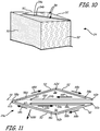
- FIGS. 10 and 11 illustrate an alternative embodiment for purge tower 24, which includes a pair of interior walls 54a and 54b in lieu of a single interior wall 54.
- each layer of this embodiment purge tower 24 may be printed with tool path 58, starting at start vertex 60, and printing a road of part or support material that follows tool path segments 58a-58f and around corner vertices 62a-62e, until stop vertex 64 is reached.
- both the start vertex 60 and the stop vertex 64 are located within interior volume 56.
- stop vertex 64 may also optionally function as another corner vertex, and tool path 58 may be directed across the top of layer 24a, as illustrated by tool path segment 58g to a subsequent stop vertex 66 located outside of purge tower 24 to wipe nozzle 18e of the print head 18 to wipe along perimeter wall 52 at tool path segment 58d (or any other suitable location along perimeter wall 52).
- purge tower 24 may also function as a tip wipe device, which further precludes the need for a separate purge station.
- system 10 may be operated in a continuous-build manner utilizing scaffolds, such as disclosed in Crump et al., U.S. Patent Application No. 13/587,009 ; Swanson et al., U.S. Patent Application No. 13/587,012 ; and Mannella, U.S. Patent Application No. 13/587,015 .
- separate purge towers 24 may be used with each subsequent 3D part, and may be formed on starter wedges along with each subsequent 3D part.
- the method of the present disclosure for performing purge operations by printing one or more purge towers is beneficial for achieving the above-discussed desired functions of a purge operation without requiring the use of separate purge stations.
- the purge towers e.g., purge towers 24 and 74
- the purge towers are generated as 3D parts/support structures, they may be implemented entirely by software/firmware changes to controller 46 and/or computer 50 rather than with hardware changes.
- the above-discussed method may be readily retrofitted into existing additive manufacturing systems for immediate use. This is particularly useful for establishing printing farms of additive manufacturing systems, which may require full automation of the systems to print numerous 3D parts over extended durations (e.g., over days, weeks, or months).
Description
- The present disclosure relates to additive manufacturing systems for printing or otherwise building three-dimensional (3D) parts with layer-based, additive manufacturing techniques. In particular, the present disclosure relates to purge operation techniques for use in extrusion-based additive manufacturing systems.
- Additive manufacturing systems are used to print or otherwise build 3D parts from digital representations of the 3D parts (e.g., AMF and STL format files) using one or more additive manufacturing techniques. Examples of commercially available additive manufacturing techniques include extrusion-based techniques, jetting, selective laser sintering, powder/binder jetting, electron-beam melting, and stereolithographic processes. For each of these techniques, the digital representation of the 3D part is initially sliced into multiple horizontal layers. For each sliced layer, a tool path is then generated, which provides instructions for the particular additive manufacturing system to print the given layer.
- For example, in an extrusion-based additive manufacturing system, a 3D part may be printed from a digital representation of the 3D part in a layer-by-layer manner by extruding a flowable part material. The part material is extruded through an extrusion tip or nozzle carried by a print head of the system, and is deposited as a sequence of roads on a substrate in an x-y plane. The extruded part material fuses to previously deposited part material, and solidifies upon a drop in temperature. The position of the print head relative to the substrate is then incremented along a z-axis (perpendicular to the x-y plane), and the process is then repeated to form a 3D part resembling the digital representation.
- In fabricating 3D parts by depositing layers of a part material, supporting layers or structures are typically built underneath overhanging portions or in cavities of 3D parts under construction, which are not supported by the part material itself. A support structure may be built utilizing the same deposition techniques by which the part material is deposited. The host computer generates additional geometry acting as a support structure for the overhanging or free-space segments of the 3D part being formed. Support material is then deposited from a second nozzle pursuant to the generated geometry during the printing process. The support material adheres to the part material during fabrication, and is removable from the completed 3D part when the printing process is complete.
- An aspect of the present disclosure is directed to a method for printing a 3D part with an additive manufacturing system according to claim 1. The method includes printing layers of the 3D part and of a support structure for the 3D part from multiple print heads using an extrusion-based, additive manufacturing technique, and switching the print heads between stand-by modes and operating modes in-between the printing of the layers of the 3D part and the support structure. The method also includes performing a purge operation for each print head switched to the operating mode, where the purge operation includes printing a layer of at least one purge tower from the print head switched to the operating mode.
- Another aspect of the present disclosure is directed to a method for printing a 3D part with an additive manufacturing system, which includes bringing a first print head or deposition line from a stand-by mode to an operating mode, printing a first layer of a purge tower from a support material using the first print head or deposition line in the operating mode, and printing a layer of a support structure from the support material using the first print head in the operating mode after printing the first layer of the purge tower. The method also includes bringing a second print head or deposition line from a stand-by mode to an operating mode, printing a second layer of the purge tower from a part material using the second print head or deposition line in the operating mode, and printing a layer of the 3D part from the part material using the second print head in the operating mode after printing the second layer of the purge tower.
- Another aspect of the present disclosure is directed to a method for printing a 3D part with an additive manufacturing system, which includes printing a first layer of a support structure for the 3D part, printing a first layer of a purge tower from a part material, and printing a first layer of the 3D part on at least a portion of the first layer of the support structure from the part material after printing the first layer of the purge tower. The method also includes printing a second layer of the purge tower from the support material, and printing a second layer of the support structure on at least a portion of the first layer of the 3D part from the support structure after printing the second layer of the purge tower.
- Unless otherwise specified, the following terms as used herein have the meanings provided below:
- The terms "preferred" and "preferably" refer to embodiments of the invention that may afford certain benefits, under certain circumstances. However, other embodiments may also be preferred, under the same or other circumstances. Furthermore, the recitation of one or more preferred embodiments does not imply that other embodiments are not useful, and is not intended to exclude other embodiments from the scope of the present disclosure.
- Directional orientations such as "above", "below", "top", "bottom", and the like are made with reference to a layer-printing direction of a 3D part. In the embodiments shown below, the layer-printing direction is the upward direction along the vertical z-axis. In these embodiments, the terms "above", "below", "top", "bottom", and the like are based on the vertical z-axis. However, in embodiments in which the layers of 3D parts are printed along a different axis, such as along a horizontal x-axis or y-axis, the terms "above", "below", "top", "bottom", and the like are relative to the given axis.
- The term "providing", such as for "providing a print head", when recited in the claims, is not intended to require any particular delivery or receipt of the provided item. Rather, the term "providing" is merely used to recite items that will be referred to in subsequent elements of the claim(s), for purposes of clarity and ease of readability.
- The terms "about" and "substantially" are used herein with respect to measurable values and ranges due to expected variations known to those skilled in the art (e.g., limitations and variabilities in measurements).
-
-
FIG. 1 is a top, front perspective view of an additive manufacturing system in use with consumable assemblies for printing 3D parts, support structures, and a purge tower of the present disclosure. -
FIG. 2A is a perspective view of a print head and guide tube for use with the additive manufacturing system. -
FIG. 2B is an exploded perspective view of the print head. -
FIG. 3A is a perspective view of a printed 3D part, support structure, and purge tower on a build substrate. -
FIG. 3B is a top view of the printed 3D part, support structure, and purge tower on the build substrate. -
FIG. 4 is a perspective view of a top portion of the purge tower. -
FIG. 5 is a top view of a layer of the purge tower, illustrating a process for printing the layer. -
FIG. 6 is a side view of simplified layers of a printed 3D part, support structure, and purge tower on a build substrate. -
FIG. 7 is a side view of the printed 3D part, support structure, and purge tower on the build substrate. -
FIG. 8 is a perspective view of a printed 3D part, support structure, purge tower, and a separate purge layer on a build substrate, which illustrates a first alternative purge tower embodiment. -
FIG. 9 is a perspective view of a printed 3D part, support structure, and multiple purge towers on a build substrate, which illustrates a second alternative purge tower embodiment. -
FIG. 10 is a perspective view of a top portion of a first alternative purge tower. -
FIG. 11 is a top view of a layer of the first alternative purge tower, illustrating a process for printing the layer. - The present disclosure is directed to a method for printing 3D parts and support structures using an additive manufacturing system with the use of a purge tower (or multiple purge towers). As briefly mentioned above, in fabricating 3D parts by depositing layers of a part material, one or more support structures may be built underneath overhanging portions or in cavities of 3D parts under construction, which are not supported by the part material itself. The support structures are preferably printed from a support material that is removable from the associated 3D part after the printing operation is completed.
- To accomplish this, the additive manufacturing system may utilize multiple print heads or deposition lines, where a first print head or deposition line may be used to print the 3D part, and a second material print head or deposition line may be used to print the support structure. For ease of discussion, the following disclosure is made with reference to separate print heads for printing 3D parts and support structures, referred to as a "part print head" and a "support print head". Examples of such part and support print heads include those disclosed in
Swanson et al., U.S. Publication Nos. 2010/0283172 and2012/0164256 . However, the method of the present disclosure is equally applicable for use with a single deposition head having multiple deposition lines for printing 3D parts and support structures. Examples of such deposition heads include those disclosed in Leavitt,U.S. Patent No. 7,625,200 , andLaBossiere et al., U.S. Patent No. 7,604,470 . - When printing with multiple print heads (or multiple deposition lines), each print head or deposition line is switchable between an "operating mode" and a "stand-by mode". The operating mode is preferably a mode in which a liquefier assembly of the print head to be heated to its set point operating temperature(s) to generate a desired thermal gradient for melting the part or support material. In comparison, the stand-by mode is preferably a mode in which the liquefier assembly of the print head is cooled down from its operating mode to prevent its part or support material from thermally degrading, oozing or dripping out.
- Additionally, in some embodiments, when switching between the operating mode and the stand-by mode, one or more of the print heads are lifted, pivoted, or otherwise moved relative to the build plane and/or each other, such as also disclosed in Leavitt,
U.S. Patent No. 7,625,200 ,LaBossiere et al., U.S. Patent No. 7,604,470 , andSwanson et al., U.S. Publication Nos. 2010/0283172 and2012/0164256 . For example, when switching from the operating mode to the stand-by mode, a print head may be lifted, pivoted, or otherwise moved away from the build plane by a small distance to prevent interference with the printed layers. Then, when subsequently switched back to its operating mode, the print head moved back to its original distance relative to the build plane for printing a subsequent layer. - Typically, when the part print head is in its operating mode to print a layer of the 3D part, the support print head is its stand-by mode, and vice versa. For example, after a 3D part layer is completed, the additive manufacturing system may then switch the print heads such that the support print head is brought to its operating mode to print a layer of the support structure, and the part print head is brought to its stand-by mode. Then, after the support structure layer is completed, the additive manufacturing system may switch the print heads back such that the part print head is brought to its operating mode to print a layer of the support structure, and the part print head is brought to its stand-by mode.
- When each print head is brought to its operating mode, it undergoes a purge operation prior to printing the next layer. As discussed in
Turley et al., U.S. Patent No. 7,744,364 , a purge operation conventionally involves moving the given print head to a purge station, where it extrudes a strand of the part or support material into a purge bucket, optionally followed by a tip wipe operation. Performing purge operations and creating blocks of waste material during layer-wise manufacturing is furthermore also known fromWO2012085914A1 . - This purge operation provides several desired functions. First, it frees any part or support material filament that may be adhered to the walls of the liquefier assembly, and verifies that the print head can extrude the part or support material. It also removes any entrained gases and degraded materials in the print head, and brings the print head to a known operating state for printing the subsequent layer, such as bringing a meniscus in the liquefier assembly to a substantially known position and raising the internal temperature of the liquefier assembly to a substantially steady-state condition. It also removes variable ooze that may hang from a nozzle of the liquefier assembly while the print head is idle or in its stand-by mode, and can account for variability of any voids in a tip pipe region of the nozzle. Additionally, for very low-volume-per-layer 3D parts, it may provide a minimum flow volume per layer to reduce the residence time-at-temperature for the part material.
- However, the use of a purge station typically requires a sufficient amount of the part or support material to be extruded from the print head to have enough weight to fall away from the given print head and into a purge bucket. Furthermore, the purge station itself can take up a sizeable footprint in the additive manufacturing system, which may reduce the usable build volume for printing 3D parts. Moreover, the purge buckets periodically need to be emptied of the accumulate purged strands. This can inhibit the additive manufacturing system from functioning in a fully automated manner, such as in a printer farm.
- As such, the method of the present disclosure is directed to a process in which the part and support print heads print a purge tower (or multiple purge towers) during the purge operations. As discussed below, the purge tower allows each print head to achieve the above-discussed desired functions of a purge operation without requiring the use of a separate purge station. This can increase the useable build volume in the additive manufacturing system, as well as reducing the amount of part and support materials consumed during the purge operations and allowing the additive manufacturing system to operate in a fully automated manner.
-
FIG. 1 showssystem 10 in use with twoconsumable assemblies 12, which illustrates a suitable additive manufacturing system for performing the method of the present disclosure to print 3D parts and support structures along with one or more purge towers. Eachconsumable assembly 12 is an easily loadable, removable, and replaceable container device that retains a supply of a consumable filament for printing withsystem 10. Typically, one of theconsumable assemblies 12 contains a part material filament ("part material consumable assembly"), and the otherconsumable assembly 12 contains a support material filament ("support material consumable assembly"). However, bothconsumable assemblies 12 may be identical in structure. - In the shown embodiment, each
consumable assembly 12 includescontainer portion 14,guide tube 16, print heads 18, where print heads 18 are individually referred to aspart print head 18p (for the part material) andsupport print head 18s (for the support material).Container portion 14 may retain a spool or coil of a consumable filament, such as discussed inMannella et al., U.S. Publication Nos. 2013/0161442 A1 and2013/0161432 A1 .Guide tube 16interconnects container portion 14 andprint head 18, where a drive mechanism of print head 18 (or of system 10) draws successive segments of the consumable filament fromcontainer portion 14, throughguide tube 16, to a liquefier assembly of theprint head 18. - In this embodiment, guide
tube 16 andprint head 18 are subcomponents ofconsumable assembly 12, and may be interchanged to and fromsystem 10 with eachconsumable assembly 12. In alternative embodiments, guidetube 16 and/orprint head 18 may be components ofsystem 10, rather than subcomponents ofconsumable assemblies 12. - Suitable part and support materials for
consumable assemblies 12 include those disclosed and listed inCrump et al., U.S. Patent No. 5,503,785 ;Lombardi et al., U.S. Patent Nos. 6,070,107 and6,228,923 ;Priedeman et al., U.S. Patent No. 6,790,403 ;Comb et al., U.S. Patent No. 7,122,246 ;Batchelder, U.S. Patent Application Publication No. 2009/0263582 ;Hopkins et al., U.S. Patent Application Publication No. 2010/0096072 ;Batchelder et al., U.S. Patent Application Publication No. 2011/0076496 ; andBatchelder et al., U.S. Patent Application Publication No. 2011/0076495 . -
System 10 is an additive manufacturing system for printing 3D parts or models and corresponding support structures (e.g.,3D part 20 and support structure 22) from the part and support material filaments, respectively, ofconsumable assemblies 12, using a layer-based, additive manufacturing technique. Additionally, as described further below,system 10 may also printpurge tower 24 from the part and support materials during purge operations. - Suitable additive manufacturing systems for
system 10 include extrusion-based systems developed by Stratasys, Inc., Eden Prairie, MN under the trademarks "FDM" and "FUSED DEPOSITION MODELING". As shown,system 10 includes system casing 26, twobays 28,chamber 30,platen 32,platen gantry 34,head carriage 36,head gantry 38, z-axis motor 40, and a pair ofx-y motors 42. -
System casing 26 is a structural component ofsystem 10 and may include multiple structural sub-components such as support frames, housing walls, and the like. In the shown embodiment, system casing 26 defines the dimensions ofbays 28, and ofchamber 30.Bays 28 are container bays configured to respectively receivecontainer portions 14 ofconsumable assemblies 12. Typically, each ofbays 28 may be intended to receive either a partmaterial consumable assembly 12 or a support materialconsumable assembly 12. - In an alternative embodiment,
bays 28 may be omitted to reduce the overall footprint ofsystem 10. In this embodiment,container portions 14 may stand adjacent to system casing 26, while providing sufficient ranges of movement forguide tubes 16 and print heads 18.Bays 28, however, provide convenient locations for loadingconsumable assemblies 12. -
Chamber 30 is an enclosed environment that containsplaten 32 forprinting 3D part 20 andsupport structure 22.Chamber 30 may be heated (e.g., with circulating heated air) to reduce the rate at which the part and support materials solidify after being extruded and deposited (e.g., to reduce distortions and curling). In alternative embodiments,chamber 30 may be omitted and/or replaced with different types of build environments. For example,3D part 20 andsupport structure 22 may be built in a build environment that is open to ambient conditions or may be enclosed with alternative structures (e.g., flexible curtains). -
Platen 32 is a platform on which3D part 20,support structure 22, and purgetower 24 are printed in a layer-by-layer manner, and is supported byplaten gantry 34. In some embodiments,platen 32 may engage and support abuild substrate 44, which may be a tray substrate as disclosed inDunn et al., U.S. Patent No. 7,127,309 , fabricated from plastic, corrugated cardboard, or other suitable material, and may also include a flexible polymeric film or liner, painter's tape, polyimide tape (e.g., under the trademark KAPTON from E.I. du Pont de Nemours and Company, Wilmington, DE), or other disposable fabrication for adhering deposited material onto theplaten 32 or onto thebuild substrate 44.Platen gantry 34 is a gantry assembly configured to move platen 32 along (or substantially along) the vertical z-axis and is powered by z-axis motor 40. -
Head carriage 36 is a unit configured to receive one or more removable print heads, such as print heads 18, and is supported byhead gantry 38. Examples of suitable devices forhead carriage 36, and techniques for retainingprint heads 18 inhead carriage 36, include those disclosed inSwanson et al., U.S. Publication Nos. 2010/0283172 and2012/0164256 . - As mentioned above, in some embodiments, guide
tube 16 and/orprint head 18 may be components ofsystem 10, rather than subcomponents ofconsumable assemblies 12. In these embodiments, additional examples of suitable devices for print heads 18, and the connections between print heads 18 andhead gantry 38 include those disclosed inCrump et al., U.S. Patent No. 5,503,785 ;Swanson et al., U.S. Patent No. 6,004,124 ;LaBossiere, et al., U.S. Patent Nos. 7,384,255 and7,604,470 ;Batchelder et al., U.S. Patent No. 7,896,209 ; andComb et al., U.S. Patent No. 8,153,182 . - In the shown embodiment,
head gantry 38 is a belt-driven gantry assembly configured to move head carriage 36 (and the retained print heads 18) in (or substantially in) a horizontal x-y plane abovechamber 30, and is powered byx-y motors 42. Examples of suitable gantry assemblies forhead gantry 38 include those disclosed inComb et al., U.S. Publication No. 2013/0078073 A1 . - In an alternative embodiment,
platen 32 may be configured to move in the horizontal x-y plane withinchamber 30, and head carriage 36 (and print heads 18) may be configured to move along the z-axis. Other similar arrangements may also be used such that one or both ofplaten 32 andprint heads 18 are moveable relative to each other.Platen 32 and head carriage 36 (and print heads 18) may also be oriented along different axes. For example,platen 32 may be oriented vertically andprint heads 18 may print3D part 20 andsupport structure 22 along the x-axis or the y-axis. -
System 10 may also include a pair of sensor assemblies (not shown) configured to read encoded markings from successive segments of the consumable filaments moving throughguide tubes 16, such as disclosed inBatchelder et al., U.S. Patent Publication Nos. 2011/0117268 ,2011/0121476 , and2011/0233804 . -
System 10 also includescontroller 46, which is one or more control circuits configured to monitor and operate the components ofsystem 10. For example, one or more of the control functions performed bycontroller 46 can be implemented in hardware, software, firmware, and the like, or a combination thereof.Controller 46 may communicate overcommunication line 48 withprint heads 18, chamber 30 (e.g., with a heating unit for chamber 30),head carriage 36,motors sensor assemblies 44, and various sensors, calibration devices, display devices, and/or user input devices. In some embodiments,controller 46 may also communicate with one or more ofbays 28,platen 32,platen gantry 34,head gantry 38, and any other suitable component ofsystem 10. - While illustrated as a single signal line,
communication line 48 may include one or more electrical, optical, and/or wireless signal lines, allowingcontroller 46 to communicate with various components ofsystem 10. Furthermore, while illustrated outside ofsystem 10,controller 46 andcommunication line 48 may be internal components tosystem 10.System 10 and/orcontroller 46 may also communicate with one or more computer-based systems, such ascomputer 50, which may include computer-based hardware, such as data storage devices, processors, memory modules and the like for generating, storing, and transmitting tool path and related printing instructions tosystem 10, and may be external and/or internal tosystem 10. In some embodiments,controller 46 itself may perform one or more of the operations typically performed bycomputer 50 or other components ofsystem 10, such as generating and storing tool path and related printing instructions, perform compiler functions, and the like. - During operation,
controller 46 may direct z-axis motor 40 andplaten gantry 34 to move platen 32 to a predetermined height withinchamber 30.Controller 46 may then directmotors 42 andhead gantry 38 to move head carriage 36 (and the retained print heads 18) around in the horizontal x-y plane abovechamber 30.Controller 46 may also direct print heads 18 to selectively draw successive segments of the consumable filaments fromcontainer portions 14 and throughguide tubes 16, respectively. -
FIGS. 2A and 2B illustrate anexample print head 18, which includeshousing 18a,motor assembly 18b,drive mechanism 18c, andliquefier assembly 18d, whereliquefier assembly 18d includesnozzle 18e. At eachprint head 18,motor assembly 18b and drivemechanism 18c feed successive segments of the consumable filament toliquefier assembly 18d, which thermally melts the received successive segments such that the consumable filament becomes a molten material. The molten material is then extruded fromnozzle 18e and deposited ontoplaten 32 forprinting 3D part 20,support structure 22, and purgetower 24 in a layer-by-layer manner. - As discussed in
Swanson et al., U.S. Patent Application No. 13/587,002 ,nozzle 18e may have an axial channel any suitable length-to-diameter ratio. For example, in some embodiments,nozzle 18e may have an axial channel with a length-to-diameter ratio to generate high flow resistance, such as a ratio of about 2:1 to about 5:1. In other embodiments,nozzle 18e may have an axial channel with a length-to-diameter ratio to generate lower flow resistance, such as a ratio less than about 1:1. Accordingly, suitable length-to-diameter ratios for the axial channel ofnozzle 18e may range from about 1:2 to about 5:1, where in some low-flow resistance embodiments, ratios ranging from about 1:2 to about 1:1 may be preferred for use with the method of the present disclosure. - After the print operation is complete, the resulting
3D part 32 andsupport structure 22 may be removed fromchamber 30, andsupport structure 22 may be removed from3D part 20.Purge tower 24 itself may be then recycled or otherwise discarded as desired.3D part 20 may then undergo one or more additional post-processing steps. - As shown in
FIG. 1 , and further shown inFIGS. 3A and 3B ,purge tower 24 may be printed at any suitable free location on build substrate 44 (i.e., at any location in the x-y build plane not occupied by3D part 20 or support structure 22). As discussed further below, each layer ofpurge tower 24 is printed by either the part material or by the support material depending on when print heads 18 switch between their operating modes and their stand-by modes and perform the purge operations. - As further shown in
FIGS. 4 ,purge tower 24 is printed in a layer-by-layer manner to defineperimeter wall 52 andinterior wall 54, whereperimeter wall 52 has a diamond-shaped cross-sectional geometry in the x-y build plane that definesinterior volume 56.Interior wall 54 resides insideinterior volume 56, and, in the shown embodiment, bisects or substantially bisectsinterior volume 56. This is a particularly suitable geometry forprinting purge tower 24 at fast print rates and with low amounts of materials since, for each layer,perimeter wall 52 andinterior start wall 54 may be printed from a single tool path. This accordingly reduces delays and material consumption during the purge operations. However, in other embodiments, one or more of the layers ofpurge tower 24 may be printed with two or more tool paths. - In alternative embodiments,
purge tower 24 may have any suitable perimeter wall geometry that preferably defines an interior volume that is substantially enclosed in the x-y build plane for retaining aninterior wall 52. Examples of suitable perimeter wall geometries include square walls, rectangular walls, circular walls, elliptical walls, and the like, where single-tool path, simple geometries are preferred for fast print rate purposes. - As shown in
FIG. 5 , each layer of purge tower 24 (referred to aslayer 24a) is preferably printed along the same tool path 58, which has astart vertex 60,corner vertices 62a-62d, and stopvertex 64, andtool path segments 58a-58a extending therebetween. As mentioned above,controller 46 may direct one of print heads 18 to perform a purge operation by printing alayer 24a ofpurge tower 24 after the givenprint head 18 switches from its stand-by mode to its operating mode, and prior to printing a subsequent layer of3D part 20 orsupport structure 22. - When performing the purge operation,
controller 46 may directhead gantry 36 to move theprint head 18 over to startvertex 60.Controller 46 may then direct a drive mechanism of theprint head 18 to feed the part or support material filament to theprint head 18 to extrude the part or support material.Controller 46 may also directhead gantry 36 to move theprint head 18 alongtool path segments 58a-58e in the direction ofarrows 68a-68e. Upon reachingstop vertex 64,controller 46 may direct theprint head 18 to stop extruding the part or support material to completelayer 24a. - This tool path pattern is beneficial for containing any excess stringing at the extrusion start up to a region within
interior volume 56. In other words,perimeter wall 52 prevents any stringing that may occur from exitingpurge tower 24, which could otherwise potentially interfere with the printing of3D part 20 orsupport structure 22 due to the close proximity ofpurge tower 24 and 3D part 20 (compared to the offset locations of conventional purge stations). - The length of
tool path segment 58a betweenstart vertex 60 and thefirst corner vertex 62a may vary depending on the stringing conditions of theprint head 18, which may be based on multiple factors, such as the thermal properties of theprint head 18, the composition of the part or support material, the extrusion rate and movement rate ofprint head 18, the temperature withinchamber 30, the amount of degraded materials and gases accumulated in theprint head 18 during its stand-by mode, and the like. The lengths oftool path segments 58b-58e may accordingly be based on the length oftool path segment 58a. - Furthermore, while illustrated as extending entirely across
interior volume 56,tool path segment 58a may alternatively be shorter, such that start vertex may be positioned at any suitable location relative to thefirst corner vertex 62a to contain the excess stringing to a region withininterior volume 56. Overall, the entire length of tool path 58 is preferably sufficient such that theprint head 18 attains a known operating state for printing the subsequent layer of3D part 20 orsupport structure 22, and more preferably such thatprint head 18 achieves all of the above-discussed desired functions of a purge operation (without requiring the use of a separate purge station). - Optionally, as shown, stop
vertex 64 may alternatively function as another corner vertex, and tool path 58 may be directed across the top oflayer 24a, such as illustrated bytool path segment 58f to asubsequent stop vertex 66 located outside ofpurge tower 24. However, when followingtool path segment 58f,controller 46 preferably directs theprint head 18 not to extrude any material. Instead, the movement of the print head alongtool path segment 58f (or any other similar tool path segment) allowsnozzle 18e of theprint head 18 to wipe alongperimeter wall 52 attool path segment 58c. As such,purge tower 24 may also function as a tip wipe device, which further precludes the need for a separate purge station. - As mentioned above, each
layer 24a ofpurge tower 24 is preferably printed along the same tool path 58. However, in situations in whichpurge tower 24 will be printed high enough that its height is substantially greater than its cross-sectional area, it can be beneficial to print thelower layers 24a ofpurge tower 24 with larger cross-sectional areas, with walls that slope or taper to small cross-sectional areas at the higher layers. This preferably prevents to the portion ofpurge tower 24 from wobbling during the printing operation, which can otherwise impair the printing of subsequent layers. - Computer 50 (or controller 46) may generate tool path instructions for
printing purge tower 24 at any suitable time before and/or during the printing operation. In a first embodiment,purge tower 24 may be generated when slicing and generating supports for3D part 20. For example, upon receipt of a digital model for3D part 20,computer 50 may run a pre-processing program to slice3D part 20 into the separate layers, generatesupport structure 22, and generate tool paths for3D part 20 andsupport structure 22. Examples of suitable pre-processing programs includes those developed by Stratasys, Inc., Eden Prairie, MN under the trademarks "INSIGHT" and "CATALYST", which may be modified to generate the tool paths (e.g., tool path 58) for each layer ofpurge tower 24. - In a second embodiment, the tool paths for
purge tower 24 may be post-processed into the previously-generated tool path instructions with a separate post-processing program (after running the pre-processing program). This post-processing program may operated manually by a user, or may be invoked in an automated manner by the pre-processing program and/orcontroller 46. - In a third embodiment, the tool paths for
purge tower 24 may be compiled bycomputer 50 during the printing operation. In this embodiment, whensystem 10 is printing a given layer,computer 50 may look ahead at the generated tool path instructions and identify when the next material switch will occur. At this point,computer 50 may compile and insert a tool path (e.g., tool path 58) forpurge tower 24 in the timing sequence to occur after thenext print head 18 switch. Preferably,computer 50 may also compute the amount of part or support material required to print the given layer ofpurge tower 24 to ensure thatconsumable assemblies 12 still have enough supplies of the part or support materials to complete the printing operation. - The particular material used for each
layer 24a depends on whichprint head 18 will be switched from its stand-by mode to its operating mode for the given layer of3D part 20 andsupport structure 22. This timing typically depends on when the tool paths for the layers of3D part 20 andsupport structure 22 require material switching. For instance,FIG. 6 illustrates a simplified layer arrangement for a3D part 70 andsupport structure 72 that may be printed withsystem 10, where3D part 70 is printed frompart print head 18p with part layers 70a-70d, andsupport structure 72 is printed fromsupport print head 18s withsupport layers 72a-72d (shown with speckle fill). In this example, print heads 18 may also printpurge tower 74 from the part and support materials during the purge operations. - As shown, the first two printed
layers support structure 72. As such, prior toprinting support layer 72a onbuild substrate 44,support print head 18s may be brought to its operating mode and undergo a purge operation byprinting layer 74a ofpurge tower 74 from the support material, preferably following the same tool path 58 discussed above for purge tower 24 (shown inFIG. 5 ).Support print head 18s may then printsupport layer 72a from the support material following designated tool paths. Whensupport layer 72a is completed,platen gantry 34 may lowerplaten 32 and buildsubstrate 44 downward along the z-axis by a single layer increment. - Then, because
support layer 72b is also printed entirely from the support material,support print head 18s may printsupport layer 72b following designated tool paths, and thenprint layer 74b ofpurge tower 74 from the support material. Alternatively, if desired, the tool path configuration may be arranged such thatsupport print head 18s printslayer 74b prior toprinting support layer 72b.Support layer 72b is necessary for maintainingpurge tower 74 at the same height as the printed layers of3D part 70 andsupport structure 72. - When layers 72b and 74b are completed,
platen gantry 34 may thenlower platen 32 and buildsubstrate 44 downward along the z-axis by a single layer increment. As can be seen, layers 70a and 72c are coplanar with each other. As such, becausesupport print head 18s is thecurrent print head 18 in its operating mode (part print head 18p is currently in its stand-by mode),support layer 72c may be printed prior topart layer 70a. Accordingly,support print head 18s may printsupport layer 72c from the support material following designated tool paths. - Then, print heads 18 may be switched such that
support print head 18s is brought to its stand-by mode andpart print head 18p is brought to its operating mode.Part print head 18p may then undergo a purge operation byprinting layer 74c ofpurge tower 74 from the part material, preferably following the same tool path 58 discussed above forpurge tower 24.Part print head 18p may then printpart layer 70a from the part material following designated tool paths. Whenpart layer 70a is completed,platen gantry 34 may lowerplaten 32 and buildsubstrate 44 downward along the z-axis by a single layer increment. - The next layers 70b and 72d are also coplanar with each other. As such, because
part print head 18p is thecurrent print head 18 in its operating mode (support print head 18s is currently in its stand-by mode),part layer 70b may be printed prior to supportlayer 72d. Accordingly,part print head 18p may printpart layer 70b from the part material following designated tool paths. - Then, print heads 18 may be switched back such that
part print head 18p is brought to its stand-by mode and supportprint head 18s is brought to its operating mode.Support print head 18s may then undergo a purge operation byprinting layer 74d ofpurge tower 74 from the support material.Support print head 18s may then printsupport layer 72d from the support material following designated tool paths. Whensupport layer 72d is completed,platen gantry 34 may lowerplaten 32 and buildsubstrate 44 downward along the z-axis by a single layer increment. - Then, because
support layer 70c is printed entirely from the part material, and becausesupport print head 18s is thecurrent print head 18 in its operating mode, print heads 18 may be switched such thatsupport print head 18s is brought to its stand-by mode andpart print head 18p is brought to its operating mode.Part print head 18p may then undergo a purge operation byprinting layer 74e ofpurge tower 74 from the part material.Part print head 18p may then printpart layer 70c from the part material following designated tool paths. Whenpart layer 70a is completed,platen gantry 34 may lowerplaten 32 and buildsubstrate 44 downward along the z-axis by a single layer increment. - Then, because
part layer 70d is also printed entirely from the part material, and becausepart print head 18p is thecurrent print head 18 in its operating mode,print head 18p may printpart layer 70d following designated tool paths. At this point, because there are no further layers ofsupport structure 72, there will be no further switching between operating and stand-by modes for print heads 18. In particular,purge tower 70 can be stopped at the highest layer at which there is a material change (i.e., a switch from part to support material, or vice versa) Accordingly, additional layers forpurge tower 24 are no longer necessary, and may be omitted. On the other hand, if additional support layers forsupport structure 72 are to be subsequently printed, additional layers of purge tower may be printed from the part material with each layer of3D part 70 until the next print head switching and purge operation is required. -
FIG. 7 illustrates a suitable example forprinting 3D part 20,support structure 22, and purgetower 24 in the same manner, where3D part 20 has abase portion 20a, ashaft portion 20b, and an overhangingtop portion 20c. Similarly,support structure 22 has ananchor portion 22a that supports and anchorsbase portion 20a to buildsubstrate 44, and anupper portion 22b that supports overhangingtop portion 20c and encapsulatesshaft portion 20b. - As further shown, the layers of
3D part 20 andsupport structure 22 may be grouped intostack regions 76a-76e. Atstack region 76a, the layers only include the support material foranchor portion 22a. Above that, atstack region 76b, each layer includes the part material forbase portion 20a and the support material foranchor portion 22a. Then, atstack region 76c, the layers only include the part material forbase portion 20a. Above that, atstack region 76d, each layer includes the part material forshaft portion 20b and the support material forupper portion 22b. Finally, atstack region 76e, the layers only include the part material for overhangingtop portion 20c. - As discussed above for purge tower 74 (show in
FIG. 6 ), the layers ofpurge tower 24 may also stagger and interlace between the part and support materials in patterns that are based on the layer patterns ofstack regions 76a-76e. For example, prior to printing the layers foranchor portion 22a ofsupport structure 22,support print head 18s may switch to its operating mode and perform a purge operation by printing a first layer ofpurge tower 24 ontobuild substrate 44 from the support material.Support print head 18s may then print the first layer ofanchor portion 22a ontobuild substrate 44 from the support material. - The printing of
purge tower 24 andanchor portion 22a may then be repeated for each layer instack region 76a, whereplaten gantry 32 may incrementallylower platen 30 andplaten substrate 44 downward by a single layer increment between each printed layer. As such, the layers ofpurge tower 24 atstack region 76a may be printed entirely from the support material, and purgetower 24 preferably has the same height as the printed layers ofanchor portion 22a. - After the last layer in
stack region 76a is completed, andplaten gantry 32 lowersplaten 30 andplaten substrate 44 downward by a single layer increment, the situation changes because the next layer increment (i.e., the first layer instack region 76b) includes a layer ofbase portion 20a (i.e., part material) and a layer ofanchor portion 22a (i.e., support material). As such, becausesupport print head 18s is thecurrent print head 18 in its operating mode,support print head 18s may print the layer ofanchor portion 22a from the support material. Print heads 18 may then be switched such thatsupport print head 18s is brought to its stand-by mode andpart print head 18p is brought to its operating mode.Part print head 18p may then undergo a purge operation by printing the next layer ofpurge tower 24 from the part material, and then print the layer forbase portion 20a. - After the current layer is completed,
platen gantry 32 may lowerplaten 30 andplaten substrate 44 downward by a single layer increment, andpart print head 18p may print the next layer ofbase portion 20a from the part material. Print heads 18 may then be switched such thatpart print head 18p is brought to its stand-by mode and supportprint head 18s is brought to its operating mode.Support print head 18s may then undergo a purge operation by printing the next layer ofpurge tower 24 from the support material, and then print the layer foranchor portion 22a. - This back-and-forth switching may then be repeated for each layer in
stack region 76b following the same pattern as discussed above for part layers 70a and 70b, support layers 72c and 72d (shown inFIG. 6 ), and purge tower layers 74c and 74d. As such, forstack region 76b, the layers ofpurge tower 24 have an interlaced pattern that switches back and forth between the part material and the support material on a layer-by-layer basis. - After the last layer in
stack region 76b is completed, andplaten gantry 32 lowersplaten 30 andplaten substrate 44 downward by a single layer increment, the situation changes again because the next layer (i.e., the first layer instack region 76c) includes only the part material forbase portion 20a. As such, ifsupport print head 18s is currently theprint head 18 in its operating mode, print heads 18 may be switched such thatsupport print head 18s is brought to its stand-by mode andpart print head 18p is brought to its operating mode.Part print head 18p undergo a purge operation by printing the next layer ofpurge tower 24 from the part material. - Alternatively, if
part print head 18p is currently theprint head 18 in its operating mode, it may remain in its operating mode, and print the next layer ofpurge tower 24 from the part material to maintain the height ofpurge tower 24.Part print head 18p may then print each successive layer ofbase portion 20a and purgetower 24 instack region 76c from the part material, whereplaten gantry 32 may incrementallylower platen 30 andplaten substrate 44 downward by a single layer increment between each printed layer. As such, the layers ofpurge tower 24 atstack region 76c may be printed entirely from the part material, and purgetower 24 preferably has the same height as the printed layers ofbase portion 20a. - After the last layer in
stack region 76c is completed, andplaten gantry 32 lowersplaten 30 andplaten substrate 44 downward by a single layer increment, the situation changes again because the next layer (i.e., the first layer instack region 76d) includes a layer ofshaft portion 20b (i.e., part material) and a layer ofupper portion 22b (i.e., support material). As such, becausepart print head 18p is thecurrent print head 18 in its operating mode at this point,part print head 18p may print the first layer ofshaft portion 22b from the part material. - Print heads 18 may then be switched such that
part print head 18p is brought to its stand-by mode and supportprint head 18s is brought to its operating mode.Support print head 18s may then undergo a purge operation by printing the next layer ofpurge tower 24 from the support material, and then print the first layer forupper portion 22b. The same back-and-forth switching as discussed above forstack region 76b may then be repeated for each layer instack region 76d. As such, forstack region 76d, the layers ofpurge tower 24 have an interlaced pattern that switches back and forth between the part material and the support material on a layer-by-layer basis. - After the last layer in
stack region 76b is completed, andplaten gantry 32 lowersplaten 30 andplaten substrate 44 downward by a single layer increment, the situation changes again because the next layer (i.e., the first layer instack region 76e) includes only the part material for overhanging top 20c. As such, ifsupport print head 18s is currently theprint head 18 in its operating mode, print heads 18 may be switched such thatsupport print head 18s is brought to its stand-by mode andpart print head 18p is brought to its operating mode.Part print head 18p undergo a purge operation by printing the next layer ofpurge tower 24 from the part material. - Alternatively, if
part print head 18p is currently theprint head 18 in its operating mode, it may remain in its operating mode, and print the next layer ofpurge tower 24 from the part material to maintain the height ofpurge tower 24.Part print head 18p may then print each successive layer of overhanging top instack region 76e from the part material, whereplaten gantry 32 may incrementallylower platen 30 andplaten substrate 44 downward by a single layer increment between each printed layer. - At this point, because there are no subsequent layers of
support structure 22, no additional layers ofpurge tower 24 are required, as shown. As mentioned above,purge tower 24 can be stopped at the highest layer at which there is a material change (i.e., a switch from part to support material, or vice versa). As such, atstack region 76e, purge tower only requires a single part material layer ifpart print head 18p was required to be switched to its operating mode for a purge operation. Otherwise, subsequent layers ofpurge tower 24 may be omitted to reduce material consumption and printing time. - As discussed above,
3D part 20 is preferably printed on one or more layers of support structure 22 (i.e.,anchor portion 22a) to anchor3D part 20 to buildsubstrate 44. This can assist in reducing curl in3D part 20 during the printing operation. However, alternative printing instructions may produce a situation where the first layer to be printed onbuild substrate 44 includes tool paths for the 3D part (i.e., part material) and tool paths for the support structure (i.e., support material). In this case, two purge operations will be required for printing the first layer. - However, because
purge tower 24 needs to grow at the same layer rate as the 3D part/support structure, both purge operations cannot be stacked atpurge tower 24. Instead, as shown inFIG. 8 , one of the purge operations will require a second tool path location (as a single layer 78) laterally adjacent to the first layer ofpurge tower 24. The remaining purge operations may then be printed on top of the first layer ofpurge tower 24. - Alternatively, as shown in
FIG. 9 , two or more grown purge towers (referred to purgetowers 24p and 24s) may be used. In this embodiment,purge tower 24p may be printed entirely from the part material, and purge tower 24s may be printed entirely from the support material. As such, for each layer of3D part 20 and/orsupport structure 22, a layer of part material is printed forpurge tower 24p and a layer of support material is printed for purge tower 24s. As can be appreciated, this embodiment is less preferred to that shown above with the integrated part/supportmaterial purge tower 24, but may function as a usable alternative for performing purge operations. -
FIGS. 10 and 11 illustrate an alternative embodiment forpurge tower 24, which includes a pair ofinterior walls interior wall 54. As shown inFIG. 11 , each layer of thisembodiment purge tower 24 may be printed with tool path 58, starting atstart vertex 60, and printing a road of part or support material that followstool path segments 58a-58f and aroundcorner vertices 62a-62e, untilstop vertex 64 is reached. As such, in this embodiment, both thestart vertex 60 and thestop vertex 64 are located withininterior volume 56. - This is beneficial for containing any excess stringing that may occur after the extrusion is stopped to the region within
interior volume 56, along with any excess stringing that may occur at the start point, as discussed above. In this embodiment, stopvertex 64 may also optionally function as another corner vertex, and tool path 58 may be directed across the top oflayer 24a, as illustrated bytool path segment 58g to asubsequent stop vertex 66 located outside ofpurge tower 24 to wipenozzle 18e of theprint head 18 to wipe alongperimeter wall 52 attool path segment 58d (or any other suitable location along perimeter wall 52). As such, in this embodiment,purge tower 24 may also function as a tip wipe device, which further precludes the need for a separate purge station. - In some embodiments,
system 10 may be operated in a continuous-build manner utilizing scaffolds, such as disclosed inCrump et al., U.S. Patent Application No. 13/587,009 ;Swanson et al., U.S. Patent Application No. 13/587,012 ; andMannella, U.S. Patent Application No. 13/587,015 . In these embodiments, separate purge towers 24 may be used with each subsequent 3D part, and may be formed on starter wedges along with each subsequent 3D part. - Accordingly, the method of the present disclosure for performing purge operations by printing one or more purge towers (e.g., purge towers 24 and 74) is beneficial for achieving the above-discussed desired functions of a purge operation without requiring the use of separate purge stations. Additionally, because the purge towers (e.g., purge towers 24 and 74) are generated as 3D parts/support structures, they may be implemented entirely by software/firmware changes to
controller 46 and/orcomputer 50 rather than with hardware changes. As such, the above-discussed method may be readily retrofitted into existing additive manufacturing systems for immediate use. This is particularly useful for establishing printing farms of additive manufacturing systems, which may require full automation of the systems to print numerous 3D parts over extended durations (e.g., over days, weeks, or months).
Claims (15)
- A method for printing a three-dimensional part (20, 70) with an additive manufacturing system (10), the method comprising:printing layers of the three-dimensional part (20, 70) and of a support structure (22, 72) for the three-dimensional part (20, 70) from multiple print heads (18) using an extrusion-based, additive manufacturing technique;switching the print heads (18) between stand-by modes and operating modes in-between the printing of the layers of the three-dimensional part (20, 70) and the support structure (22, 72);performing a purge operation for each print head (18) switched from the standby mode to the operating mode, the purge operation comprising printing at least one purge tower (24, 74) in a layer by layer manner, wherein the layers (24a, 74c) of the at least one purge tower (24, 74) are extruded directly from the print head 18 switched to the operating mode.
- The method of claim 1, wherein the multiple print heads (18) comprise a first print head (18p) and a second print head (18s), and wherein switching the print heads (18) between the stand-by modes and the operating modes comprises:switching the first print head (18p) from the stand-by mode to the operating mode; andswitching the second print head (18s) from the operating mode to the stand-by mode.
- The method of claim 1 or 2, wherein printing the layers (24a, 74c) of the at least one purge tower (24, 74) comprises:printing along a first tool path segment (58a) between a start vertex (60) and a first corner vertex (62a);printing along one or more additional tool path segments (58b, 58c, 58d, 58e) from the first corner vertex (62a) to a stop vertex (64), which at least partially encases the first tool path segment (58a) in a build plane.
- The method of claim 1 or 3, wherein the at least one purge tower (24, 74) has a cross-sectional area that reduces in height along an axis that is perpendicular to a build plane.
- The method of claim 1 or 4, wherein the at least one purge tower (24) is stopped at a highest layer at which there is a material change for the printed layers of the three-dimensional part (20, 70) and support structure (22, 72).
- The method of claim 1, and further comprising:generating tool path instructions for printing the layers of the three-dimensional part (20, 70) and of the support structure (22, 72);generating tool path instructions for printing the layer (24a, 74c) of the at least one purge tower (24, 74); andprinting the purge tower within a same chamber (30) of the additive manufacturing system (10) as the three-dimensional part (20, 70).
- The method of claim 6, wherein the generating of the tool path instructions for printing the layer (24a, 74c) of the at least one purge tower (24, 74) is performed after extruding a portion of the layers of the three-dimensional part (20, 70), after extruding a portion of the layers of the support structure (22, 72), or both.
- The method of claim 6, wherein the generating of the tool path instructions for printing the layer of the at least one purge tower (24, 74) is performed prior to printing the layers of the three-dimensional part (20, 70) and of the support structure (22, 72).
- The method of claim 2, wherein bringing the first print head (18p) from the stand-by mode to the operating mode comprises heating a liquefier assembly (18d) of the first print head (18p).
- The method of claim 1, and further comprising printing layers (24a, 74c) of the purge tower (24, 74) such that the purge tower (24, 74) maintains the same height perpendicular to a build plane the printed layers of the three-dimensional part (20, 70) and support structure (22, 72).
- The method of claim 1 and further comprising:(a) printing the layer (74a) of the support structure (22, 72) for the three-dimensional part (20, 70);(b) printing the layer (24a, 74c) of the purge tower (24, 74) from the part material;(c) printing the layer of the three-dimensional part (20, 70) on at least a portion of the layer (74a) of the support structure (22, 72) from the part material after printing the layer (24a, 74c) of the purge tower (24, 74);(d) printing a second layer (74d) of the purge tower (24, 74) from the support material; and(e) printing a second layer (72b) of the support structure (22, 72) on at least a portion of the first layer of the three-dimensional part (20, 70) from the support structure (22, 72) after printing the second layer (72d) of the purge tower (24, 74).
- The method of claim 11, and further comprising repeating steps (b) - (e) for at least a portion of the three-dimensional part (20, 70) and support structure (22, 72).
- The method of claim 12, wherein at least a portion of the layers (74c) of the purge tower (74) are interlaced between the part material and the support material on a layer-by-layer basis.
- The method of claim 11, wherein the purge tower (24, 74) comprises a perimeter wall (52) and an interior wall (54) printed from a single tool path (58), wherein for each extruding layer of the purge tower (24, 74), the interior wall (54) is extruding prior to the printing of the perimeter wall (52).
- The method of claim 14, wherein the perimeter wall (52) defines a diamond-shape cross-sectional geometry in a build plane.
Applications Claiming Priority (2)
| Application Number | Priority Date | Filing Date | Title |
|---|---|---|---|
| US13/790,924 US9421713B2 (en) | 2013-03-08 | 2013-03-08 | Additive manufacturing method for printing three-dimensional parts with purge towers |
| PCT/US2014/017915 WO2014137637A1 (en) | 2013-03-08 | 2014-02-24 | Additive manufacturing method for printing three-dimensional parts with purge towers |
Publications (4)
| Publication Number | Publication Date |
|---|---|
| EP2964450A1 EP2964450A1 (en) | 2016-01-13 |
| EP2964450A4 EP2964450A4 (en) | 2017-03-08 |
| EP2964450B1 true EP2964450B1 (en) | 2020-08-26 |
| EP2964450B2 EP2964450B2 (en) | 2024-05-08 |
Family
ID=51486903
Family Applications (1)
| Application Number | Title | Priority Date | Filing Date |
|---|---|---|---|
| EP14760240.3A Active EP2964450B2 (en) | 2013-03-08 | 2014-02-24 | Additive manufacturing method for printing three-dimensional parts with purge towers |
Country Status (4)
| Country | Link |
|---|---|
| US (1) | US9421713B2 (en) |
| EP (1) | EP2964450B2 (en) |
| CN (1) | CN105189091B (en) |
| WO (1) | WO2014137637A1 (en) |
Cited By (1)
| Publication number | Priority date | Publication date | Assignee | Title |
|---|---|---|---|---|
| NL2032639B1 (en) * | 2022-07-29 | 2024-02-06 | Ultimaker Bv | Method of printing a three-dimensional (3D) object with an FFF system |
Families Citing this family (38)
| Publication number | Priority date | Publication date | Assignee | Title |
|---|---|---|---|---|
| GB201212629D0 (en) | 2012-07-16 | 2012-08-29 | Prec Engineering Technologies Ltd | A machine tool |
| WO2017035217A1 (en) * | 2015-08-25 | 2017-03-02 | New York University | 3d manufacturing using multiple material deposition and/or fusion sources simultaneously with single or multi-flute helical build surfaces |
| US9527240B2 (en) | 2013-03-15 | 2016-12-27 | Stratasys, Inc. | Additive manufacturing system and method for printing three-dimensional parts using velocimetry |
| US20150056317A1 (en) * | 2013-08-23 | 2015-02-26 | Xyzprinting, Inc. | Three-dimensional printing apparatus |
| US9931791B2 (en) | 2013-09-29 | 2018-04-03 | Makerbot Industries, Llc | Three-dimensional printing with multi-material support |
| US9688025B2 (en) * | 2014-01-08 | 2017-06-27 | Adobe Systems Incorporated | 3D cleaning object for multi-print-head 3D printing |
| US9658613B2 (en) | 2014-01-22 | 2017-05-23 | Omax Corporation | Generating optimized tool paths and machine commands for beam cutting tools |
| WO2016038356A1 (en) | 2014-09-08 | 2016-03-17 | University Of Central Lancashire | Solid dosage form production |
| CN104589655B (en) * | 2015-01-30 | 2017-07-18 | 江苏浩宇电子科技有限公司 | 3D printer is with interchangeable assembly parts fast-connecting type structure |
| USD810747S1 (en) * | 2015-06-01 | 2018-02-20 | Xyzprinting, Inc. | Three dimensional scanning device |
| TWI600529B (en) * | 2015-07-16 | 2017-10-01 | 研能科技股份有限公司 | Full color 3d printing device |
| US10792868B2 (en) | 2015-09-09 | 2020-10-06 | Carbon, Inc. | Method and apparatus for three-dimensional fabrication |
| US10562289B2 (en) * | 2015-10-30 | 2020-02-18 | Stratasys, Inc. | Print foundation positioning and printing methods for additive manufacturing system |
| US10562227B2 (en) | 2015-12-01 | 2020-02-18 | Massachusetts Institute Of Technology | Systems, devices, and methods for high-throughput three-dimensional printing |
| US10583606B2 (en) * | 2016-02-11 | 2020-03-10 | General Electric Company | Method and supports with powder removal ports for additive manufacturing |
| US20180001552A1 (en) * | 2016-06-30 | 2018-01-04 | Carbon, Inc. | Method and apparatus for three-dimensional fabrication of continuous sheets of material |
| US10513107B2 (en) | 2016-08-15 | 2019-12-24 | Stratasys, Inc. | Lever tray release |
| US10632732B2 (en) | 2016-11-08 | 2020-04-28 | 3Dbotics, Inc. | Method and apparatus for making three-dimensional objects using a dynamically adjustable retaining barrier |
| US20180169971A1 (en) * | 2016-12-21 | 2018-06-21 | The Boeing Company | Fused filament fabrication machine |
| JP2018130836A (en) * | 2017-02-13 | 2018-08-23 | 株式会社リコー | Three-dimensional molding apparatus and purge device |
| RU2654313C1 (en) * | 2017-05-04 | 2018-05-17 | Федеральное государственное автономное образовательное учреждение высшего образования "Национальный исследовательский университет "Московский институт электронной техники" | Method for forming three-dimensional structures of topological elements of functional layers on the surface of the substrates |
| CN107168162B (en) * | 2017-05-25 | 2021-10-08 | 北京东软医疗设备有限公司 | Control device |
| TWI711533B (en) | 2017-05-26 | 2020-12-01 | 三緯國際立體列印科技股份有限公司 | Three dimensional printing method |
| US10656626B2 (en) * | 2017-06-01 | 2020-05-19 | Proto Labs, Inc. | Methods and software for manufacturing a discrete object from an additively manufactured body of material including a precursor to a discrete object and a reference feature(s) |
| CN109421255B (en) * | 2017-08-31 | 2020-12-15 | 三纬国际立体列印科技股份有限公司 | 3D printing method using reinforced auxiliary wall |
| US10449719B2 (en) * | 2017-12-01 | 2019-10-22 | Bulent Besim | System for feeding filament to a nozzle in an additive manufacturing machine |
| US10859997B1 (en) | 2017-12-04 | 2020-12-08 | Omax Corporation | Numerically controlled machining |
| CN108058387B (en) * | 2017-12-12 | 2019-12-20 | 共享智能装备有限公司 | Planning method of FDM printing path |
| US11554461B1 (en) | 2018-02-13 | 2023-01-17 | Omax Corporation | Articulating apparatus of a waterjet system and related technology |
| US11117329B2 (en) | 2018-06-26 | 2021-09-14 | General Electric Company | Additively manufactured build assemblies having reduced distortion and residual stress |
| US11371788B2 (en) | 2018-09-10 | 2022-06-28 | General Electric Company | Heat exchangers with a particulate flushing manifold and systems and methods of flushing particulates from a heat exchanger |
| US11440097B2 (en) | 2019-02-12 | 2022-09-13 | General Electric Company | Methods for additively manufacturing components using lattice support structures |
| USD900179S1 (en) * | 2019-03-20 | 2020-10-27 | Makerbot Industries, Llc | Extruder for a three-dimensional printer |
| EP3996898B1 (en) * | 2019-07-09 | 2023-09-06 | Signify Holding B.V. | Printing structures with openings in a side surface |
| US11630439B2 (en) * | 2019-08-22 | 2023-04-18 | Ut-Battelle, Llc | Continuous toolpaths for additive manufacturing |
| CN112172127B (en) * | 2020-04-22 | 2021-05-11 | 上海复志信息技术有限公司 | Control method and control system for printing nozzle rapid moving path and storage medium |
| US11668314B2 (en) | 2020-11-10 | 2023-06-06 | Greenheck Fan Corporation | Efficient fan assembly |
| CN113232289B (en) * | 2021-04-04 | 2022-06-28 | 宁波大学 | Electric jet printing device and method for preparing nano arched structure |
Citations (3)
| Publication number | Priority date | Publication date | Assignee | Title |
|---|---|---|---|---|
| WO2008156870A1 (en) | 2007-06-21 | 2008-12-24 | Stratasys, Inc. | Extrusion tip cleaning assembly |
| US20120164256A1 (en) | 2010-12-22 | 2012-06-28 | Stratasys, Inc. | Print head assembly and print head for use in fused deposition modeling system |
| WO2012085914A1 (en) | 2010-12-21 | 2012-06-28 | Objet Ltd. | Method and system for reuse of materials in additive manufacturing systems |
Family Cites Families (71)
| Publication number | Priority date | Publication date | Assignee | Title |
|---|---|---|---|---|
| GB2229702B (en) | 1989-02-04 | 1992-09-30 | Draftex Ind Ltd | Strip handling apparatus |
| US5121329A (en) | 1989-10-30 | 1992-06-09 | Stratasys, Inc. | Apparatus and method for creating three-dimensional objects |
| JP2597778B2 (en) | 1991-01-03 | 1997-04-09 | ストラタシイス,インコーポレイテッド | Three-dimensional object assembling system and assembling method |
| US5312224A (en) | 1993-03-12 | 1994-05-17 | International Business Machines Corporation | Conical logarithmic spiral viscosity pump |
| US5503785A (en) | 1994-06-02 | 1996-04-02 | Stratasys, Inc. | Process of support removal for fused deposition modeling |
| US5764521A (en) | 1995-11-13 | 1998-06-09 | Stratasys Inc. | Method and apparatus for solid prototyping |
| US5738817A (en) | 1996-02-08 | 1998-04-14 | Rutgers, The State University | Solid freeform fabrication methods |
| US6085957A (en) | 1996-04-08 | 2000-07-11 | Stratasys, Inc. | Volumetric feed control for flexible filament |
| US6070107A (en) | 1997-04-02 | 2000-05-30 | Stratasys, Inc. | Water soluble rapid prototyping support and mold material |
| US6067480A (en) | 1997-04-02 | 2000-05-23 | Stratasys, Inc. | Method and apparatus for in-situ formation of three-dimensional solid objects by extrusion of polymeric materials |
| US6228923B1 (en) | 1997-04-02 | 2001-05-08 | Stratasys, Inc. | Water soluble rapid prototyping support and mold material |
| US5866058A (en) | 1997-05-29 | 1999-02-02 | Stratasys Inc. | Method for rapid prototyping of solid models |
| US5968561A (en) | 1998-01-26 | 1999-10-19 | Stratasys, Inc. | High performance rapid prototyping system |
| US6004124A (en) | 1998-01-26 | 1999-12-21 | Stratasys, Inc. | Thin-wall tube liquifier |
| US5939008A (en) | 1998-01-26 | 1999-08-17 | Stratasys, Inc. | Rapid prototyping apparatus |
| US6022207A (en) | 1998-01-26 | 2000-02-08 | Stratasys, Inc. | Rapid prototyping system with filament supply spool monitoring |
| US6129872A (en) | 1998-08-29 | 2000-10-10 | Jang; Justin | Process and apparatus for creating a colorful three-dimensional object |
| US6054077A (en) | 1999-01-11 | 2000-04-25 | Stratasys, Inc. | Velocity profiling in an extrusion apparatus |
| US6645412B2 (en) | 1999-04-20 | 2003-11-11 | Stratasys, Inc. | Process of making a three-dimensional object |
| EP1194274B1 (en) | 1999-04-20 | 2017-03-22 | Stratasys, Inc. | Process for three-dimensional modeling |
| US6776602B2 (en) | 1999-04-20 | 2004-08-17 | Stratasys, Inc. | Filament cassette and loading system |
| US6722872B1 (en) | 1999-06-23 | 2004-04-20 | Stratasys, Inc. | High temperature modeling apparatus |
| US6257517B1 (en) | 1999-08-10 | 2001-07-10 | Sandvik Steel Co. | Method and apparatus for feeding welding wire |
| US6730252B1 (en) | 2000-09-20 | 2004-05-04 | Swee Hin Teoh | Methods for fabricating a filament for use in tissue engineering |
| US6749414B1 (en) | 2001-04-30 | 2004-06-15 | Stratasys, Inc. | Extrusion apparatus for three-dimensional modeling |
| US6547995B1 (en) | 2001-09-21 | 2003-04-15 | Stratasys, Inc. | Melt flow compensation in an extrusion apparatus |
| US6866807B2 (en) | 2001-09-21 | 2005-03-15 | Stratasys, Inc. | High-precision modeling filament |
| US6814907B1 (en) | 2001-12-18 | 2004-11-09 | Stratasys, Inc. | Liquifier pump control in an extrusion apparatus |
| CN103358550B (en) * | 2003-05-01 | 2016-03-30 | 斯特拉特西斯有限公司 | Rapid molding device |
| US6869559B2 (en) | 2003-05-05 | 2005-03-22 | Stratasys, Inc. | Material and method for three-dimensional modeling |
| US7261533B2 (en) | 2003-10-21 | 2007-08-28 | Align Technology, Inc. | Method and apparatus for manufacturing dental aligners |
| US7127309B2 (en) | 2004-02-10 | 2006-10-24 | Stratasys, Inc. | Modeling apparatus with tray substrate |
| US7481647B2 (en) | 2004-06-14 | 2009-01-27 | Align Technology, Inc. | Systems and methods for fabricating 3-D objects |
| US6976627B1 (en) | 2004-11-12 | 2005-12-20 | Align Technology, Inc. | Identification of units in customized production |
| US7236166B2 (en) | 2005-01-18 | 2007-06-26 | Stratasys, Inc. | High-resolution rapid manufacturing |
| US7384255B2 (en) | 2005-07-01 | 2008-06-10 | Stratasys, Inc. | Rapid prototyping system with controlled material feedstock |
| US7604470B2 (en) | 2006-04-03 | 2009-10-20 | Stratasys, Inc. | Single-motor extrusion head having multiple extrusion lines |
| US7625200B2 (en) | 2007-07-31 | 2009-12-01 | Stratasys, Inc. | Extrusion head for use in extrusion-based layered deposition modeling |
| US8070473B2 (en) | 2008-01-08 | 2011-12-06 | Stratasys, Inc. | System for building three-dimensional objects containing embedded inserts, and method of use thereof |
| CN101911084B (en) | 2008-01-08 | 2014-05-28 | 斯特拉塔西斯公司 | Consumable assembly for use in extrusion-based layered deposition systems |
| US7917243B2 (en) | 2008-01-08 | 2011-03-29 | Stratasys, Inc. | Method for building three-dimensional objects containing embedded inserts |
| US8858856B2 (en) | 2008-01-08 | 2014-10-14 | Stratasys, Inc. | Method for building and using three-dimensional objects containing embedded identification-tag inserts |
| US8215371B2 (en) | 2008-04-18 | 2012-07-10 | Stratasys, Inc. | Digital manufacturing with amorphous metallic alloys |
| US7896209B2 (en) | 2008-04-30 | 2011-03-01 | Stratasys, Inc. | Filament drive mechanism for use in extrusion-based digital manufacturing systems |
| US7897074B2 (en) | 2008-04-30 | 2011-03-01 | Stratasys, Inc. | Liquefier assembly for use in extrusion-based digital manufacturing systems |
| US8075300B2 (en) | 2008-06-30 | 2011-12-13 | Stratasys, Inc. | Vapor smoothing surface finishing system |
| US8033811B2 (en) | 2008-07-25 | 2011-10-11 | Stratasys, Inc. | Pantograph assembly for digital manufacturing system |
| US8246888B2 (en) | 2008-10-17 | 2012-08-21 | Stratasys, Inc. | Support material for digital manufacturing systems |
| US8153182B2 (en) | 2008-10-21 | 2012-04-10 | Stratasys, Inc. | Adjustable head mount for digital manufacturing system |
| US7938356B2 (en) | 2008-10-22 | 2011-05-10 | Stratasys, Inc. | Filament spool |
| US7938351B2 (en) | 2008-10-22 | 2011-05-10 | Stratasys, Inc. | Filament guide mechanism for filament spool container |
| GB0819935D0 (en) | 2008-10-30 | 2008-12-10 | Mtt Technologies Ltd | Additive manufacturing apparatus and method |
| US20100327479A1 (en) | 2009-06-23 | 2010-12-30 | Stratasys, Inc. | Consumable materials having customized characteristics |
| US8221669B2 (en) | 2009-09-30 | 2012-07-17 | Stratasys, Inc. | Method for building three-dimensional models in extrusion-based digital manufacturing systems using ribbon filaments |
| US8236227B2 (en) | 2009-09-30 | 2012-08-07 | Stratasys, Inc. | Method for building three-dimensional models in extrusion-based digital manufacturing systems using tracked filaments |
| US8439665B2 (en) | 2009-09-30 | 2013-05-14 | Stratasys, Inc. | Ribbon liquefier for use in extrusion-based digital manufacturing systems |
| US20110117268A1 (en) | 2009-11-19 | 2011-05-19 | Stratasys, Inc. | Consumable materials having encoded markings for use with direct digital manufacturing systems |
| US20110121476A1 (en) | 2009-11-19 | 2011-05-26 | Stratasys, Inc. | Encoded consumable materials and sensor assemblies for use in additive manufacturing systems |
| US9592539B2 (en) | 2010-01-05 | 2017-03-14 | Stratasys, Inc. | Support cleaning system |
| US8282380B2 (en) | 2010-08-18 | 2012-10-09 | Makerbot Industries | Automated 3D build processes |
| US9522501B2 (en) | 2010-09-21 | 2016-12-20 | The Boeing Company | Continuous linear production in a selective laser sintering system |
| US8815141B2 (en) | 2010-09-22 | 2014-08-26 | Stratasys, Inc. | Method for building three-dimensional models with extrusion-based additive manufacturing systems |
| US8647098B2 (en) | 2010-09-22 | 2014-02-11 | Stratasys, Inc. | Liquefier assembly for use in extrusion-based additive manufacturing systems |
| EP2643148B1 (en) | 2010-11-28 | 2016-02-03 | Stratasys Ltd. | System and method for additive manufacturing of an object |
| US8419996B2 (en) | 2010-12-22 | 2013-04-16 | Stratasys, Inc. | Print head assembly for use in fused deposition modeling system |
| US8460755B2 (en) | 2011-04-07 | 2013-06-11 | Stratasys, Inc. | Extrusion-based additive manufacturing process with part annealing |
| US8916085B2 (en) | 2011-06-02 | 2014-12-23 | A. Raymond Et Cie | Process of making a component with a passageway |
| US9108360B2 (en) | 2011-09-23 | 2015-08-18 | Stratasys, Inc. | Gantry assembly for use in additive manufacturing system |
| US8459280B2 (en) | 2011-09-23 | 2013-06-11 | Stratasys, Inc. | Support structure removal system |
| US9931791B2 (en) * | 2013-09-29 | 2018-04-03 | Makerbot Industries, Llc | Three-dimensional printing with multi-material support |
| US9688025B2 (en) * | 2014-01-08 | 2017-06-27 | Adobe Systems Incorporated | 3D cleaning object for multi-print-head 3D printing |
-
2013
- 2013-03-08 US US13/790,924 patent/US9421713B2/en active Active
-
2014
- 2014-02-24 CN CN201480013098.2A patent/CN105189091B/en active Active
- 2014-02-24 EP EP14760240.3A patent/EP2964450B2/en active Active
- 2014-02-24 WO PCT/US2014/017915 patent/WO2014137637A1/en active Application Filing
Patent Citations (3)
| Publication number | Priority date | Publication date | Assignee | Title |
|---|---|---|---|---|
| WO2008156870A1 (en) | 2007-06-21 | 2008-12-24 | Stratasys, Inc. | Extrusion tip cleaning assembly |
| WO2012085914A1 (en) | 2010-12-21 | 2012-06-28 | Objet Ltd. | Method and system for reuse of materials in additive manufacturing systems |
| US20120164256A1 (en) | 2010-12-22 | 2012-06-28 | Stratasys, Inc. | Print head assembly and print head for use in fused deposition modeling system |
Non-Patent Citations (3)
| Title |
|---|
| BROOKS, H. ET AL.: "Research towards high speed extrusion freeforming", INT. J. RAPID MANUFACTURING, vol. 3, no. 2,3, 2013, pages 1 - 18, XP009189669 |
| CORBETT, J.: "Reprap Colour Mixing Project", DEPARTMENT OF MECHANICAL ENGINEERING, 19 November 2012 (2012-11-19), pages 1 - 122, XP055810937, Retrieved from the Internet <URL:https://www.web.archive.org/web/ 20121119 020404/ https://www.reprap.or g/med iawiki/i mages/0/05/RepRapColourM ixing Report-jmc. pdf>> |
| OLLIVER, VIK: "First Complete Object & Tower of Ooze", REPRAP:BLOG, 13 June 2006 (2006-06-13), pages 1 - 2, XP055810934, Retrieved from the Internet <URL:https://www.web.archive.org/web/ 20111018 022939/ http://blog.reprap.org /2006/06/fi rst-com plete-object-tower-of-ooze. html >> |
Cited By (1)
| Publication number | Priority date | Publication date | Assignee | Title |
|---|---|---|---|---|
| NL2032639B1 (en) * | 2022-07-29 | 2024-02-06 | Ultimaker Bv | Method of printing a three-dimensional (3D) object with an FFF system |
Also Published As
| Publication number | Publication date |
|---|---|
| CN105189091B (en) | 2017-04-05 |
| US20140252684A1 (en) | 2014-09-11 |
| WO2014137637A1 (en) | 2014-09-12 |
| EP2964450A4 (en) | 2017-03-08 |
| EP2964450B2 (en) | 2024-05-08 |
| CN105189091A (en) | 2015-12-23 |
| US9421713B2 (en) | 2016-08-23 |
| EP2964450A1 (en) | 2016-01-13 |
Similar Documents
| Publication | Publication Date | Title |
|---|---|---|
| EP2964450B1 (en) | Additive manufacturing method for printing three-dimensional parts with purge towers | |
| US10549517B2 (en) | Additive manufacturing system with extended printing volume, and methods of use thereof | |
| US10399281B2 (en) | Additive manufacturing technique for printing three-dimensional parts with printed receiving surfaces | |
| US10661499B2 (en) | Platen planarizing process for additive manufacturing system | |
| US10035306B2 (en) | Additive manufacturing system with extended printing volume, and methods of use thereof | |
| US20190315114A1 (en) | Gear-based liquefier assembly for additive manufacturing system, and methods of use thereof | |
| US9511547B2 (en) | Method for printing three-dimensional parts with additive manufacturing systems using scaffolds | |
| US8815141B2 (en) | Method for building three-dimensional models with extrusion-based additive manufacturing systems | |
| US9233506B2 (en) | Liquefier assembly for use in additive manufacturing system | |
| US11020899B2 (en) | Additive manufacturing system with extended printing volume, and methods of use thereof | |
| US20180290398A1 (en) | Additive manufacturing system with a channeled starter piece and method of printing a 3d part utilizing the starter piece | |
| US20240083117A1 (en) | Method of printing a multi-material 3d part and purge tower |
Legal Events
| Date | Code | Title | Description |
|---|---|---|---|
| PUAI | Public reference made under article 153(3) epc to a published international application that has entered the european phase |
Free format text: ORIGINAL CODE: 0009012 |
|
| 17P | Request for examination filed |
Effective date: 20150826 |
|
| AK | Designated contracting states |
Kind code of ref document: A1 Designated state(s): AL AT BE BG CH CY CZ DE DK EE ES FI FR GB GR HR HU IE IS IT LI LT LU LV MC MK MT NL NO PL PT RO RS SE SI SK SM TR |
|
| AX | Request for extension of the european patent |
Extension state: BA ME |
|
| DAX | Request for extension of the european patent (deleted) | ||
| RIC1 | Information provided on ipc code assigned before grant |
Ipc: B29C 67/00 20060101AFI20161026BHEP Ipc: B33Y 10/00 20150101ALI20161026BHEP Ipc: B33Y 50/02 20150101ALI20161026BHEP |
|
| A4 | Supplementary search report drawn up and despatched |
Effective date: 20170206 |
|
| RIC1 | Information provided on ipc code assigned before grant |
Ipc: B33Y 10/00 20150101ALI20170131BHEP Ipc: B33Y 50/02 20150101ALI20170131BHEP Ipc: B29C 67/00 20170101AFI20170131BHEP |
|
| STAA | Information on the status of an ep patent application or granted ep patent |
Free format text: STATUS: EXAMINATION IS IN PROGRESS |
|
| 17Q | First examination report despatched |
Effective date: 20181105 |
|
| REG | Reference to a national code |
Ref country code: DE Ref legal event code: R079 Ref document number: 602014069413 Country of ref document: DE Free format text: PREVIOUS MAIN CLASS: B29C0067000000 Ipc: B29C0064165000 |
|
| GRAP | Despatch of communication of intention to grant a patent |
Free format text: ORIGINAL CODE: EPIDOSNIGR1 |
|
| STAA | Information on the status of an ep patent application or granted ep patent |
Free format text: STATUS: GRANT OF PATENT IS INTENDED |
|
| RIC1 | Information provided on ipc code assigned before grant |
Ipc: B29C 64/165 20170101AFI20200415BHEP Ipc: B29C 64/357 20170101ALI20200415BHEP Ipc: B29C 64/393 20170101ALI20200415BHEP Ipc: B29C 64/35 20170101ALI20200415BHEP Ipc: B29C 64/118 20170101ALI20200415BHEP |
|
| INTG | Intention to grant announced |
Effective date: 20200519 |
|
| GRAS | Grant fee paid |
Free format text: ORIGINAL CODE: EPIDOSNIGR3 |
|
| GRAA | (expected) grant |
Free format text: ORIGINAL CODE: 0009210 |
|
| STAA | Information on the status of an ep patent application or granted ep patent |
Free format text: STATUS: THE PATENT HAS BEEN GRANTED |
|
| AK | Designated contracting states |
Kind code of ref document: B1 Designated state(s): AL AT BE BG CH CY CZ DE DK EE ES FI FR GB GR HR HU IE IS IT LI LT LU LV MC MK MT NL NO PL PT RO RS SE SI SK SM TR |
|
| REG | Reference to a national code |
Ref country code: GB Ref legal event code: FG4D |
|
| REG | Reference to a national code |
Ref country code: CH Ref legal event code: EP |
|
| REG | Reference to a national code |
Ref country code: AT Ref legal event code: REF Ref document number: 1305958 Country of ref document: AT Kind code of ref document: T Effective date: 20200915 |
|
| REG | Reference to a national code |
Ref country code: IE Ref legal event code: FG4D |
|
| REG | Reference to a national code |
Ref country code: DE Ref legal event code: R096 Ref document number: 602014069413 Country of ref document: DE |
|
| REG | Reference to a national code |
Ref country code: NL Ref legal event code: FP |
|
| REG | Reference to a national code |
Ref country code: LT Ref legal event code: MG4D |
|
| PG25 | Lapsed in a contracting state [announced via postgrant information from national office to epo] |
Ref country code: SE Free format text: LAPSE BECAUSE OF FAILURE TO SUBMIT A TRANSLATION OF THE DESCRIPTION OR TO PAY THE FEE WITHIN THE PRESCRIBED TIME-LIMIT Effective date: 20200826 Ref country code: HR Free format text: LAPSE BECAUSE OF FAILURE TO SUBMIT A TRANSLATION OF THE DESCRIPTION OR TO PAY THE FEE WITHIN THE PRESCRIBED TIME-LIMIT Effective date: 20200826 Ref country code: FI Free format text: LAPSE BECAUSE OF FAILURE TO SUBMIT A TRANSLATION OF THE DESCRIPTION OR TO PAY THE FEE WITHIN THE PRESCRIBED TIME-LIMIT Effective date: 20200826 Ref country code: LT Free format text: LAPSE BECAUSE OF FAILURE TO SUBMIT A TRANSLATION OF THE DESCRIPTION OR TO PAY THE FEE WITHIN THE PRESCRIBED TIME-LIMIT Effective date: 20200826 Ref country code: PT Free format text: LAPSE BECAUSE OF FAILURE TO SUBMIT A TRANSLATION OF THE DESCRIPTION OR TO PAY THE FEE WITHIN THE PRESCRIBED TIME-LIMIT Effective date: 20201228 Ref country code: BG Free format text: LAPSE BECAUSE OF FAILURE TO SUBMIT A TRANSLATION OF THE DESCRIPTION OR TO PAY THE FEE WITHIN THE PRESCRIBED TIME-LIMIT Effective date: 20201126 Ref country code: NO Free format text: LAPSE BECAUSE OF FAILURE TO SUBMIT A TRANSLATION OF THE DESCRIPTION OR TO PAY THE FEE WITHIN THE PRESCRIBED TIME-LIMIT Effective date: 20201126 Ref country code: GR Free format text: LAPSE BECAUSE OF FAILURE TO SUBMIT A TRANSLATION OF THE DESCRIPTION OR TO PAY THE FEE WITHIN THE PRESCRIBED TIME-LIMIT Effective date: 20201127 |
|
| REG | Reference to a national code |
Ref country code: AT Ref legal event code: MK05 Ref document number: 1305958 Country of ref document: AT Kind code of ref document: T Effective date: 20200826 |
|
| PG25 | Lapsed in a contracting state [announced via postgrant information from national office to epo] |
Ref country code: IS Free format text: LAPSE BECAUSE OF FAILURE TO SUBMIT A TRANSLATION OF THE DESCRIPTION OR TO PAY THE FEE WITHIN THE PRESCRIBED TIME-LIMIT Effective date: 20201226 Ref country code: PL Free format text: LAPSE BECAUSE OF FAILURE TO SUBMIT A TRANSLATION OF THE DESCRIPTION OR TO PAY THE FEE WITHIN THE PRESCRIBED TIME-LIMIT Effective date: 20200826 Ref country code: LV Free format text: LAPSE BECAUSE OF FAILURE TO SUBMIT A TRANSLATION OF THE DESCRIPTION OR TO PAY THE FEE WITHIN THE PRESCRIBED TIME-LIMIT Effective date: 20200826 Ref country code: RS Free format text: LAPSE BECAUSE OF FAILURE TO SUBMIT A TRANSLATION OF THE DESCRIPTION OR TO PAY THE FEE WITHIN THE PRESCRIBED TIME-LIMIT Effective date: 20200826 |
|
| PG25 | Lapsed in a contracting state [announced via postgrant information from national office to epo] |
Ref country code: RO Free format text: LAPSE BECAUSE OF FAILURE TO SUBMIT A TRANSLATION OF THE DESCRIPTION OR TO PAY THE FEE WITHIN THE PRESCRIBED TIME-LIMIT Effective date: 20200826 Ref country code: SM Free format text: LAPSE BECAUSE OF FAILURE TO SUBMIT A TRANSLATION OF THE DESCRIPTION OR TO PAY THE FEE WITHIN THE PRESCRIBED TIME-LIMIT Effective date: 20200826 Ref country code: EE Free format text: LAPSE BECAUSE OF FAILURE TO SUBMIT A TRANSLATION OF THE DESCRIPTION OR TO PAY THE FEE WITHIN THE PRESCRIBED TIME-LIMIT Effective date: 20200826 Ref country code: CZ Free format text: LAPSE BECAUSE OF FAILURE TO SUBMIT A TRANSLATION OF THE DESCRIPTION OR TO PAY THE FEE WITHIN THE PRESCRIBED TIME-LIMIT Effective date: 20200826 Ref country code: DK Free format text: LAPSE BECAUSE OF FAILURE TO SUBMIT A TRANSLATION OF THE DESCRIPTION OR TO PAY THE FEE WITHIN THE PRESCRIBED TIME-LIMIT Effective date: 20200826 |
|
| REG | Reference to a national code |
Ref country code: DE Ref legal event code: R026 Ref document number: 602014069413 Country of ref document: DE |
|
| PG25 | Lapsed in a contracting state [announced via postgrant information from national office to epo] |
Ref country code: AT Free format text: LAPSE BECAUSE OF FAILURE TO SUBMIT A TRANSLATION OF THE DESCRIPTION OR TO PAY THE FEE WITHIN THE PRESCRIBED TIME-LIMIT Effective date: 20200826 Ref country code: AL Free format text: LAPSE BECAUSE OF FAILURE TO SUBMIT A TRANSLATION OF THE DESCRIPTION OR TO PAY THE FEE WITHIN THE PRESCRIBED TIME-LIMIT Effective date: 20200826 Ref country code: ES Free format text: LAPSE BECAUSE OF FAILURE TO SUBMIT A TRANSLATION OF THE DESCRIPTION OR TO PAY THE FEE WITHIN THE PRESCRIBED TIME-LIMIT Effective date: 20200826 |
|
| PLBI | Opposition filed |
Free format text: ORIGINAL CODE: 0009260 |
|
| PLAX | Notice of opposition and request to file observation + time limit sent |
Free format text: ORIGINAL CODE: EPIDOSNOBS2 |
|
| PG25 | Lapsed in a contracting state [announced via postgrant information from national office to epo] |
Ref country code: SK Free format text: LAPSE BECAUSE OF FAILURE TO SUBMIT A TRANSLATION OF THE DESCRIPTION OR TO PAY THE FEE WITHIN THE PRESCRIBED TIME-LIMIT Effective date: 20200826 |
|
| 26 | Opposition filed |
Opponent name: MEISSNER BOLTE PATENTANWAELTE RECHTSANWAELTE PARTNERSCHAFT MBB Effective date: 20210525 |
|
| PG25 | Lapsed in a contracting state [announced via postgrant information from national office to epo] |
Ref country code: IT Free format text: LAPSE BECAUSE OF FAILURE TO SUBMIT A TRANSLATION OF THE DESCRIPTION OR TO PAY THE FEE WITHIN THE PRESCRIBED TIME-LIMIT Effective date: 20200826 |
|
| PG25 | Lapsed in a contracting state [announced via postgrant information from national office to epo] |
Ref country code: SI Free format text: LAPSE BECAUSE OF FAILURE TO SUBMIT A TRANSLATION OF THE DESCRIPTION OR TO PAY THE FEE WITHIN THE PRESCRIBED TIME-LIMIT Effective date: 20200826 |
|
| PG25 | Lapsed in a contracting state [announced via postgrant information from national office to epo] |
Ref country code: MC Free format text: LAPSE BECAUSE OF FAILURE TO SUBMIT A TRANSLATION OF THE DESCRIPTION OR TO PAY THE FEE WITHIN THE PRESCRIBED TIME-LIMIT Effective date: 20200826 |
|
| PLBB | Reply of patent proprietor to notice(s) of opposition received |
Free format text: ORIGINAL CODE: EPIDOSNOBS3 |
|
| REG | Reference to a national code |
Ref country code: BE Ref legal event code: MM Effective date: 20210228 |
|
| PG25 | Lapsed in a contracting state [announced via postgrant information from national office to epo] |
Ref country code: CH Free format text: LAPSE BECAUSE OF NON-PAYMENT OF DUE FEES Effective date: 20210228 Ref country code: LU Free format text: LAPSE BECAUSE OF NON-PAYMENT OF DUE FEES Effective date: 20210224 Ref country code: LI Free format text: LAPSE BECAUSE OF NON-PAYMENT OF DUE FEES Effective date: 20210228 |
|
| PG25 | Lapsed in a contracting state [announced via postgrant information from national office to epo] |
Ref country code: IE Free format text: LAPSE BECAUSE OF NON-PAYMENT OF DUE FEES Effective date: 20210224 |
|
| PLBP | Opposition withdrawn |
Free format text: ORIGINAL CODE: 0009264 |
|
| PG25 | Lapsed in a contracting state [announced via postgrant information from national office to epo] |
Ref country code: BE Free format text: LAPSE BECAUSE OF NON-PAYMENT OF DUE FEES Effective date: 20210228 |
|
| PGFP | Annual fee paid to national office [announced via postgrant information from national office to epo] |
Ref country code: FR Payment date: 20230119 Year of fee payment: 10 |
|
| PG25 | Lapsed in a contracting state [announced via postgrant information from national office to epo] |
Ref country code: HU Free format text: LAPSE BECAUSE OF FAILURE TO SUBMIT A TRANSLATION OF THE DESCRIPTION OR TO PAY THE FEE WITHIN THE PRESCRIBED TIME-LIMIT; INVALID AB INITIO Effective date: 20140224 |
|
| PGFP | Annual fee paid to national office [announced via postgrant information from national office to epo] |
Ref country code: GB Payment date: 20230121 Year of fee payment: 10 Ref country code: DE Payment date: 20230119 Year of fee payment: 10 |
|
| PG25 | Lapsed in a contracting state [announced via postgrant information from national office to epo] |
Ref country code: CY Free format text: LAPSE BECAUSE OF FAILURE TO SUBMIT A TRANSLATION OF THE DESCRIPTION OR TO PAY THE FEE WITHIN THE PRESCRIBED TIME-LIMIT Effective date: 20200826 |
|
| PLAB | Opposition data, opponent's data or that of the opponent's representative modified |
Free format text: ORIGINAL CODE: 0009299OPPO |
|
| PGFP | Annual fee paid to national office [announced via postgrant information from national office to epo] |
Ref country code: NL Payment date: 20240123 Year of fee payment: 11 |
|
| PUAH | Patent maintained in amended form |
Free format text: ORIGINAL CODE: 0009272 |
|
| STAA | Information on the status of an ep patent application or granted ep patent |
Free format text: STATUS: PATENT MAINTAINED AS AMENDED |
|
| PG25 | Lapsed in a contracting state [announced via postgrant information from national office to epo] |
Ref country code: MK Free format text: LAPSE BECAUSE OF FAILURE TO SUBMIT A TRANSLATION OF THE DESCRIPTION OR TO PAY THE FEE WITHIN THE PRESCRIBED TIME-LIMIT Effective date: 20200826 |
|
| PGFP | Annual fee paid to national office [announced via postgrant information from national office to epo] |
Ref country code: DE Payment date: 20240123 Year of fee payment: 11 Ref country code: GB Payment date: 20240123 Year of fee payment: 11 |
|
| 27A | Patent maintained in amended form |
Effective date: 20240508 |
|
| AK | Designated contracting states |
Kind code of ref document: B2 Designated state(s): AL AT BE BG CH CY CZ DE DK EE ES FI FR GB GR HR HU IE IS IT LI LT LU LV MC MK MT NL NO PL PT RO RS SE SI SK SM TR |
|
| REG | Reference to a national code |
Ref country code: DE Ref legal event code: R102 Ref document number: 602014069413 Country of ref document: DE |