EP2959854A1 - Surgical instrument - Google Patents
Surgical instrument Download PDFInfo
- Publication number
- EP2959854A1 EP2959854A1 EP14173954.0A EP14173954A EP2959854A1 EP 2959854 A1 EP2959854 A1 EP 2959854A1 EP 14173954 A EP14173954 A EP 14173954A EP 2959854 A1 EP2959854 A1 EP 2959854A1
- Authority
- EP
- European Patent Office
- Prior art keywords
- sealing
- cutting electrode
- tissue
- jaws
- instrument according
- Prior art date
- Legal status (The legal status is an assumption and is not a legal conclusion. Google has not performed a legal analysis and makes no representation as to the accuracy of the status listed.)
- Granted
Links
Images


Classifications
-
- A—HUMAN NECESSITIES
- A61—MEDICAL OR VETERINARY SCIENCE; HYGIENE
- A61B—DIAGNOSIS; SURGERY; IDENTIFICATION
- A61B18/00—Surgical instruments, devices or methods for transferring non-mechanical forms of energy to or from the body
- A61B18/04—Surgical instruments, devices or methods for transferring non-mechanical forms of energy to or from the body by heating
- A61B18/12—Surgical instruments, devices or methods for transferring non-mechanical forms of energy to or from the body by heating by passing a current through the tissue to be heated, e.g. high-frequency current
- A61B18/14—Probes or electrodes therefor
- A61B18/1442—Probes having pivoting end effectors, e.g. forceps
- A61B18/1445—Probes having pivoting end effectors, e.g. forceps at the distal end of a shaft, e.g. forceps or scissors at the end of a rigid rod
-
- A—HUMAN NECESSITIES
- A61—MEDICAL OR VETERINARY SCIENCE; HYGIENE
- A61B—DIAGNOSIS; SURGERY; IDENTIFICATION
- A61B18/00—Surgical instruments, devices or methods for transferring non-mechanical forms of energy to or from the body
- A61B18/04—Surgical instruments, devices or methods for transferring non-mechanical forms of energy to or from the body by heating
- A61B18/12—Surgical instruments, devices or methods for transferring non-mechanical forms of energy to or from the body by heating by passing a current through the tissue to be heated, e.g. high-frequency current
- A61B18/14—Probes or electrodes therefor
-
- A—HUMAN NECESSITIES
- A61—MEDICAL OR VETERINARY SCIENCE; HYGIENE
- A61B—DIAGNOSIS; SURGERY; IDENTIFICATION
- A61B18/00—Surgical instruments, devices or methods for transferring non-mechanical forms of energy to or from the body
- A61B18/04—Surgical instruments, devices or methods for transferring non-mechanical forms of energy to or from the body by heating
- A61B18/12—Surgical instruments, devices or methods for transferring non-mechanical forms of energy to or from the body by heating by passing a current through the tissue to be heated, e.g. high-frequency current
- A61B18/1206—Generators therefor
-
- A—HUMAN NECESSITIES
- A61—MEDICAL OR VETERINARY SCIENCE; HYGIENE
- A61B—DIAGNOSIS; SURGERY; IDENTIFICATION
- A61B17/00—Surgical instruments, devices or methods, e.g. tourniquets
-
- A—HUMAN NECESSITIES
- A61—MEDICAL OR VETERINARY SCIENCE; HYGIENE
- A61B—DIAGNOSIS; SURGERY; IDENTIFICATION
- A61B18/00—Surgical instruments, devices or methods for transferring non-mechanical forms of energy to or from the body
- A61B2018/00053—Mechanical features of the instrument of device
- A61B2018/00184—Moving parts
- A61B2018/00196—Moving parts reciprocating lengthwise
-
- A—HUMAN NECESSITIES
- A61—MEDICAL OR VETERINARY SCIENCE; HYGIENE
- A61B—DIAGNOSIS; SURGERY; IDENTIFICATION
- A61B18/00—Surgical instruments, devices or methods for transferring non-mechanical forms of energy to or from the body
- A61B2018/00571—Surgical instruments, devices or methods for transferring non-mechanical forms of energy to or from the body for achieving a particular surgical effect
- A61B2018/00595—Cauterization
-
- A—HUMAN NECESSITIES
- A61—MEDICAL OR VETERINARY SCIENCE; HYGIENE
- A61B—DIAGNOSIS; SURGERY; IDENTIFICATION
- A61B18/00—Surgical instruments, devices or methods for transferring non-mechanical forms of energy to or from the body
- A61B2018/00571—Surgical instruments, devices or methods for transferring non-mechanical forms of energy to or from the body for achieving a particular surgical effect
- A61B2018/00601—Cutting
-
- A—HUMAN NECESSITIES
- A61—MEDICAL OR VETERINARY SCIENCE; HYGIENE
- A61B—DIAGNOSIS; SURGERY; IDENTIFICATION
- A61B18/00—Surgical instruments, devices or methods for transferring non-mechanical forms of energy to or from the body
- A61B2018/00571—Surgical instruments, devices or methods for transferring non-mechanical forms of energy to or from the body for achieving a particular surgical effect
- A61B2018/00607—Coagulation and cutting with the same instrument
-
- A—HUMAN NECESSITIES
- A61—MEDICAL OR VETERINARY SCIENCE; HYGIENE
- A61B—DIAGNOSIS; SURGERY; IDENTIFICATION
- A61B18/00—Surgical instruments, devices or methods for transferring non-mechanical forms of energy to or from the body
- A61B2018/00571—Surgical instruments, devices or methods for transferring non-mechanical forms of energy to or from the body for achieving a particular surgical effect
- A61B2018/0063—Sealing
-
- A—HUMAN NECESSITIES
- A61—MEDICAL OR VETERINARY SCIENCE; HYGIENE
- A61B—DIAGNOSIS; SURGERY; IDENTIFICATION
- A61B18/00—Surgical instruments, devices or methods for transferring non-mechanical forms of energy to or from the body
- A61B2018/00636—Sensing and controlling the application of energy
- A61B2018/00696—Controlled or regulated parameters
- A61B2018/00767—Voltage
-
- A—HUMAN NECESSITIES
- A61—MEDICAL OR VETERINARY SCIENCE; HYGIENE
- A61B—DIAGNOSIS; SURGERY; IDENTIFICATION
- A61B18/00—Surgical instruments, devices or methods for transferring non-mechanical forms of energy to or from the body
- A61B2018/00636—Sensing and controlling the application of energy
- A61B2018/00773—Sensed parameters
- A61B2018/00892—Voltage
-
- A—HUMAN NECESSITIES
- A61—MEDICAL OR VETERINARY SCIENCE; HYGIENE
- A61B—DIAGNOSIS; SURGERY; IDENTIFICATION
- A61B18/00—Surgical instruments, devices or methods for transferring non-mechanical forms of energy to or from the body
- A61B18/04—Surgical instruments, devices or methods for transferring non-mechanical forms of energy to or from the body by heating
- A61B18/12—Surgical instruments, devices or methods for transferring non-mechanical forms of energy to or from the body by heating by passing a current through the tissue to be heated, e.g. high-frequency current
- A61B18/14—Probes or electrodes therefor
- A61B18/1442—Probes having pivoting end effectors, e.g. forceps
- A61B2018/1452—Probes having pivoting end effectors, e.g. forceps including means for cutting
- A61B2018/1455—Probes having pivoting end effectors, e.g. forceps including means for cutting having a moving blade for cutting tissue grasped by the jaws
Definitions
- the invention relates to a surgical instrument for sealing and separating biological tissue.
- Sealing instruments of the type mentioned are in use for operation on living human or animal patients. They are used to detect and seal tissue under the influence of pressure and current flow and heat based on it. In addition, such instruments may serve to sever coagulated or sealed tissue.
- the US 2007/0078456 A1 discloses such an instrument with two movable branches, which serve to hold hollow vessels.
- the two branches can be supplied with electricity, so that the collected and compressed hollow vessel is heated between the branches and the vessel walls are connected to each other.
- the container closed to this extent and therefore sealed can then be severed in the sealing zone by means of a displaceable knife.
- the two branches of the tool have flat contact surfaces, between which the vessel is sealed.
- the contact surfaces must have a considerable minimum width in order to achieve a secure sealing of the vessel. That's why there are limits to the miniaturization of such tools.
- the US 2002/0115997 A1 discloses an instrument intended especially for the resection of lung tissue. It has two branches that can be moved towards and away from each other with electrode structures on both branches.
- the electrode structures are profiled on both sides of a cutting slot, through which a separating element can be moved, in such a way that grasped tissue is held in a form-fitting manner and sealed between the branches.
- both the upper and the lower branch on each side of the cutting slot each contain a positive and a negative contact in order to produce the widest possible sealing seam on the fabric.
- the sealing instrument according to the invention for The endoscopic, laparoscopic or open surgical application has two branches.
- the first industry has at least two sealing electrodes, which are preferably electrically connected to each other.
- the second branch likewise has at least two sealing electrodes, which are preferably electrically connected to one another.
- One of the sectors eg the upper one
- the other industry has a corresponding counter bearing for the cutting electrode.
- sealing electrodes are applied to create sealing seams on the biological tissue. Tissue receiving spaces are formed between the cutting electrode and the sealing jaws. These preferably have such a volume that the current density occurring there is significantly lower than between the sealing jaws.
- the tissue gripped between the cutting electrode and the sealing jaws that is to say located in the tissue receiving chambers, is flowed through electrically, but shrinks less than the tissue grasped between the jaws to form a sealing seam.
- the fabric forms at least one bead, which engages approximately positively with closed sectors both the first sealing jaws and the second sealing jaws.
- the tissue receiving space and the tissue held in it thus act as a positive securing for the captured between the sealing jaws tissue even if only a very narrow sealing seam and a very filigree tissue bulge is formed.
- the tissue can not slip out of the sealing instrument prior to opening the tool.
- This concept also opens up the possibility of working with a cutting electrode that is activated simultaneously with the sealing electrodes and thus the coagulation process and the cutting process starts at the same time.
- the tissue may be severed by the cutting electrode before the seal between the sealing jaws is completed.
- the simultaneous action of cutting electrode and sealing jaws on the tissue is not mandatory, but possible.
- the timing of cut and seal preferably adjusts itself by the voltages applied to the cutting electrode and the sealing jaws. It can thereby be achieved a shortening of the sealing and separation time and a simplification of the workflow and the electrical current supply of the instrument.
- a sealing voltage (eg, 97V) may be applied between the sealing jaws and a cutting voltage (eg, 437V) between a sealing jaw and the cutting electrode of a feed circuit simultaneously.
- the voltages can be supplied from a power transformer.
- the current supply can first be carried out with a ramp-shaped current profile and then with a constant voltage.
- the treatment can also be timed. It can be set a minimum time of 1.4 s and / or a maximum time of, for example, 2.8 s.
- the instrument or its feeding device may be provided with an overvoltage and spark detection device. To erase detected sparks, a short-term voltage reduction can be made.
- the said concept is capable of miniaturization.
- the positive securing of the vascular or tissue ends in the tissue receiving spaces can be limit the sealing zones to very narrow, almost line-like strips without fear of unsealed edges of tissue escaping prematurely from the sealing instrument.
- the tissue receiving spaces which are formed on both sides of the cutting electrode, have a shape, whereby a particularly good fit between tissue and closed instrument is achieved.
- the width of the tissue receiving spaces is greater than the width of the wall-like extension supporting the cutting electrode.
- the width of the tissue receiving spaces is preferably greater than the width of the sealing jaws. This also contributes to a positive fit and to a sufficient reduction of the current density within the tissue located in the receiving space.
- the sealing jaws preferably have a cross-sectional contour with rounded transitions.
- the sealing jaws are rounded toward the tissue receiving spaces, thereby avoiding current concentration. These curves are designed so that in addition to the lower power concentration, a secure fit between tissue and closed branches is possible.
- the sealing jaws of the two branches define sealing gaps with each other which define an obtuse angle with each other. As a result, the rounding of the sealing jaws closest to the cutting electrode can be given a large radius of curvature, which limits the current density in this case.
- the radii of curvature of the lower branch which are arranged in the direction of the tissue receiving chambers, may have a value different from the rounding radii of the upper branch. However, these radii preferably have the same values.
- the Rounding radii of the sealing jaws on the outside of the sector have greater values than the radii of curvature in the direction of the tissue receiving spaces. This allows better control of the tissue effect outside of the branches. Due to the inclination of the sealing gaps results in an automatic centering of the branches to each other.
- the sealing jaws have at their clamping surfaces radii in the direction of the tissue receiving spaces of eg 0.05 mm to 0.1 mm to achieve a good fit between tissue and instrument and radiuses on the outside of the industry, for example, 0.1 mm to 0.3 mm to achieve good sealing properties.
- the clamping surfaces define together a sealing or nip of 0 to 0.1 mm, preferably 0 to 0.05 mm, which allows a secure clamping even of thin tissue.
- the sealing jaws have a basic body with insulating regions, for example of epoxy resin, with sealing electrodes arranged in a row, for example, of the material of the main body of the industry, eg, stainless steel.
- the main body of the branches may be formed of a solid material or a stamped / bent part.
- the electrodes of opposing sealing jaws are preferably arranged or formed so as not to overlap one another.
- the insulating regions may be formed by inserts (molded or molded) inserted or molded into the industries, or by a number of local coatings of insulating material.
- an industry may be formed of ceramic, wherein it is then made conductive metallized, for example, in the region of the sealing electrodes. It is also possible to develop the industry from ceramics with different properties.
- the industry may be formed solely of ceramic, and then for the insulating regions, a non-conductive ceramic substance and for the electrode area a conductive ceramic substance.
- the insulating regions prevent electrical shorting between the sealing electrodes of the two sealing jaws, even when the sectors touch.
- the alternate longitudinal distance between electrodes of the two branches is 0.1 mm to 0.3 mm, preferably 0.25 mm.
- the sealing jaws may be provided with non-metallic material such as PTFE, synthetic resin or the like on their sides facing the tissue receiving spaces. The current flow of the cutting current is thus concentrated on the one hand on the cutting electrode and on the other hand on the captured between the sealing jaws tissue area. The risk of sticking of the tissue in the tissue receiving spaces is eliminated or significantly minimized.
- the cutting electrode carrier can be made of ceramic, plastic or an insulation-coated metal.
- the cutting electrode carrier may have a surface to which tissue does not adhere.
- the surface of the cutting electrode carrier can be coated, for example, coated in an anti-adhesive manner.
- the cutting electrode carrier has a high tracking resistance or a high CTI (Comparative Tracking Index) value, preferably greater than 600.
- the cutting electrode is preferably designed as a thin strip, which has an exposed end face carries and is anchored by suitable means, for example a plurality of feet, in or on the electrode carrier. In this way, the thermal inertia of the cutting electrode is kept to a minimum.
- the anvil may be resiliently arranged to prevent crushing of the tissue and the Cut by electrical action to lead. This benefits the sealing security, since in this way, a movement due to the tissue cutting, between the cutting electrode of the one and counter-bearing of the other industry, not to the same extent causes a branch movement and thus a movement between opposing sealing jaws.
- the cutting electrode carrier may be spring-mounted. In this case, the anvil can be rigidly attached.
- the cutting electrode carrier is made of plastic
- the cutting electrode is preferably encapsulated with plastic.
- the cutting electrode may e.g. Made of stainless steel sheet.
- the width of the cutting electrode is preferably about 0.1 mm.
- the thickness of the plastic on both sides of the cutting electrode is preferably about 0.15 mm.
- the cutting electrode preferably ends flush with the two plastic walls covering its flanks (no cutting overhang).
- a thermoset is preferably used.
- the cutting electrode in the unused state the plastic walls slightly, for example by 0.02 mm to 0.04 mm surmount. The supernatant may change during operation of the instrument, for example as a result of burning of the cutting electrode carrier.
- the cutting electrode carrier is made of ceramic, preferably ZrO 2 ceramic
- the cutting electrode carrier and the cutting electrode are prefabricated separately and then joined together.
- the width of the cutting electrode is preferably 0.2 to 0.25 mm. It can consist of a sheet metal, in particular stainless steel sheet.
- the insulating walls on both sides of the cutting electrode preferably have a thickness of 0.15 mm.
- a Cutting edge defined from 0.02 mm to 0.04 mm.
- the cutting electrode can be positively connected to the cutting electrode carrier, clamped or adhesively bonded. Typically, there is a gap between the cutting electrode and the thin insulating walls of the cutting electrode carrier. This gap can be filled with glue, silicone or similar.
- the cutting electrode may have a lateral insulation, for example of a paint or a coating such as parylene.
- a lateral insulation for example of a paint or a coating such as parylene.
- the counter electrode of the cutting electrode arranged opposite is preferably spring-mounted.
- the spring stroke can be set to less than 1mm, preferably 0.5 mm.
- the anvil serves to maintain the clamping force between the sealing jaws. This is achieved by the mechanical decoupling of the tissue clamping in the area of the sealing jaws from the tissue clamping between the cutting electrode and the abutment. Thus, the shrinkage of the fabric during cutting and sealing are decoupled from the clamping force between the sealing jaws. This effect also occurs in embodiments with rigidly arranged abutment and spring-mounted cutting electrode.
- the top or tissue support surface of the anvil sits in closed branches on a different level than the sealing jaws.
- the cutting plane of the cutting electrode protrudes beyond the sealing jaws of the sealing electrodes disposed on the same bank. Thus, the cutting process takes place on a different level than the sealing process.
- the counter bearing When the branches are open, the counter bearing can surpass the sealing jaws of the same industry. When closing the branches, the spring-elastic or spring-loaded counter bearing is then compressed and pressed into the industry. This creates the spring force that counteracts the cutting element.
- the anvil preferably consists of an insulator with non-stick surface, e.g. made of PTFE, and similar or the same creepage characteristics as the cutting electrode carrier.
- the resilient mounting of the anvil results in a cutting behavior in which the cutting gap adapts to the tissue shrinkage during the cut.
- the elongated anvil can spring independently of its distal end at its proximal end and thus also define a wedge-shaped gap with the cutting electrode if different tissue thicknesses are present along the cutting electrode.
- the anvil can be mounted rigidly or also resiliently movable in this case. It is also possible to pivot one of the elements about a transverse axis and resiliently support the other element, e.g. with a particularly small spring stroke of e.g. Less than 0.5 mm to achieve a good adaptation of the cutting electrode and the abutment to different tissue strengths along the cutting electrode.
- the processes are sealing vessels and separating (cutting) vessels at the same time.
- the separation of vessels may be completed before the sealing of the vessels ends.
- the tissue containment spaces, during the process of vessel sealing secure the tissue spaces within the branches until the completion of the sealing process. Due to the inventive construction of the industries in conjunction with the manner of the invention of the energy supply processing, in particular the separation and sealing of vessels can be done in the highest quality.
- the entire machining process is short overall because of the simultaneous start of sealing and cutting, and generally takes no longer than the seal on its own.
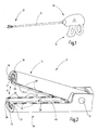
- an instrument 10 is illustrated with an elongate shaft 11 carrying a tool 12 at its distal end.
- the proximal end of the shaft 11 is connected to a housing 13 on which actuating elements 14 for movement and actuation of the tool 12 are arranged.
- the instrument 10 is a sealing instrument.
- the tool 12 serves for sealing and, if appropriate, severing tissue, wherein vessels and lumens contained in the tissue are intended to be closed and thus sealed at the resulting tissue space.
- the provided on the instrument 10 tool 12 is formed in a special way. It has a first industry 15, in FIG. 2 the top industry, and a second industry 16, in FIG. 2 the lower sector, on, of which at least one is pivotally mounted about a pivot axis 17.
- the first branch 15 or the second branch 16 or both branches 15, 16 may be pivotable or otherwise movably mounted about a common or about different pivot axes, so that the branches 15, 16 are moved towards and away from each other can.
- the industries 15, 16 are in the Figures 3 and 4 again separately illustrated in cross section.
- the first industry 15 may for example consist of metal or other resistant to bending material. It has a base body 18 with a U-profile-shaped cross-section.
- the base body 18 has two mutually parallel first sealing jaws 19, 20, which are preferably electrically connected to each other, and which define a groove 21 between each other. This preferably extends over most of the length of the first sector 15 and serves to receive a cutting electrode carrier 22.
- This has a foot 23 which is adapted to the contour of the groove 21 is and stationary, immobile in this sitting.
- a wall-like projection 24 extends away from the foot 23 which is rectangular in cross-section, for example, so that it projects out of the groove 21.
- the groove 21 is bounded by the edges of the sealing jaws 19, 20, on which sealing electrodes 25, 26 are formed.
- the foot surface 23a is arranged offset from the sealing electrodes 25, 26.
- the sealing electrodes 25, 26 may be electrically conductively connected to the base body 18.
- the sealing electrodes 25, 26 form, as in particular FIG. 2 shows, preferably a series of spaced apart conductive individual surfaces, which are separated by insulating regions 27, 28 from each other.
- the industry 15 may also include an electrically insulating coating 29 such that electrical current introduced into the industry 15 is confined only to the sealing electrodes 25, 26 in biological tissue 30 (FIG. FIG. 4 ) can be initiated. There is preferably a distance between the insulating coating 29 and the insulating regions 27, 28, so that the material of the sealing electrodes is not insulated in this region. This achieves a good sealing quality.
- the cutting electrode carrier 22 has a cutting electrode 31, which is arranged on its end face.
- the cutting electrode 31 sits in a groove or recess of the wall-like extension 24, wherein the cutting electrode 31 is exposed with an end face 32.
- the cutting electrode 31 is gripped between two groove walls 33, 34.
- the groove walls 33, 34 preferably have a width which is about as large as the width of the cutting electrode 31. It is on FIG. 6 Referenced.
- the width B of the cutting electrode 31 may be in the range of 0.05 to 0.25 mm and is preferably 0.1 mm.
- the insulating groove walls 33, 34 preferably have a thickness of the same order of magnitude. For example, they have a thickness of 0.15 mm. They close to a small supernatant with each other.
- the supernatant U of the end face 32 of the cutting electrode 31 via the end faces of the groove walls 33, 34 is only a few 10 microns, for example 0 to 40 microns.
- the length of the wall-like extension 24, measured from the foot 23 to the cutting electrode 31, is preferably designed so that the end face 32 projects beyond the sealing jaws 19, 20 by approximately 0.5 to 1 mm, preferably 0.9 mm. Accordingly, the fabric support surface 44 of the second industry 16 is approximately the same distance in the second branch by the wall-like extension 24 of the first sector 15 in the closed state of the branches in which the sealing jaws 19, 36 and 20, 37 touch 16 pushed in. This measure is in FIG. 3 indicated to the right of the tool 12 as a measure T.
- FIG. 3 further apparent is the second industry 16, which also has a base body 35, preferably made of electrically conductive material.
- the main body 35 in turn has a U-shaped cross section, in which between two second sealing jaws 36, 37, a groove 38 is formed.
- sealing electrodes 39, 40 are formed ( FIG. 2 ) arranged in a row along the upper edges of the sealing jaws 36, 37.
- the sealing electrodes 39, 40 are shorter in the jaw longitudinal direction than the insulating regions 27, 28 of the first branch 15.
- the sealing electrodes 25, 26 of the first branch 15 are in the jaw longitudinal direction shorter, than the insulating regions 61, 62, that is, the distances between the second sealing electrodes 39, 40 of the second branch 16.
- the first sealing electrodes 25, 26 are positioned on the first branch 15 in such a way that when closing the branches 15, 16 between the second sealing electrodes 39, 40, ie, to the insulating portions 61, 62 of the second branch 16 meet. In this way, an electrical short circuit between the first industry 15 and the second industry 16 is not possible.
- the second industry 16 can, like FIG. 3 shows, in turn, be provided with an insulating coating 41.
- an abutment 42 is arranged for the cutting electrode 31.
- the abutment 42 may be movably mounted parallel to the sealing jaws 36, 37 and, for example, against the force of a spring element 43 in the groove 38 hineinindbarbar.
- the anvil 42 is, for example, a plastic or ceramic or other electrical non-conductor existing strip-like element 44 with flat tissue support surface which forms a contact surface for the biological tissue 30 and in the rest position below the sealing electrodes 39, 40, ie within the groove 38.
- the tissue support surface 44 may also be structured or formed in a curve shape or a combination thereof.
- the spring element 43 may be a compression spring, which is supported at one end on the bottom of the groove 38 and at the other end is in operative connection with the counter-bearing 42. Also, a plurality of such compression springs may be arranged along the industry 16 in a row. Alternatively, an elastomeric element may rest or be fixed as a spring on the groove bottom, on which the abutment 42 is supported.
- the resilient stroke of the anvil 42 can be relatively be low and limited, for example, to less than one millimeter, preferably 0.5 mm.
- this stroke is reduced to, for example, 0.5 mm or less, with a non-preloaded spring element 43, this stroke also includes the path with which the preload is and can be generated 1 mm or larger.
- the functions of the abutment 42 and the spring element 43 can be realized in one component, for example a component made of elastomer.
- the sealing jaws 36, 37 are rounded on their upper side. They limit with the sealing jaws 19, 20 of the first sector 15 in pairs a gap 45, 46 whose orientation in FIG. 3 indicated by dash-dotted lines 47, 48.
- the orientation of the gaps 45, 46 may be determined by planar facets 49, 50, 51, 52 provided on the sealing jaws 19, 20, 36, 37.
- the directions defined by the columns 45, 46 defined by the lines 47, 48 form an obtuse angle with a vertex S marking the vertex of the angle. This points to the cutting electrode 31.
- the obtuse angle is in a range of 130 to 150 °.
- the function-determining geometry of the tool 12 also includes two tissue receiving spaces 53, 54. These are formed on both sides of the wall-like extension 24 and include portions of the grooves 21 and 38. They are vertically bounded between the foot 23 and the tissue support surface 44 of the anvil 42. This vertical extent V is in FIG. 3 registered 4 and is closed sectors without tissue, for example in the range of 0.7 mm to 2.5 mm, preferably 1.4 mm.
- the gap 45, 46 is approximately centrally with respect to the vertical extent V of the tissue receiving space 53 or 54 or preferably slightly offset to the foot surface 23a out.
- the two tissue receiving spaces 53, 54 are preferably of equal size. They have a horizontal extent H, which is determined by the distance between the wall-like extension 24 and the respective sealing jaws 19, 36 and 20, 37. This horizontal extent H is preferably significantly greater than the thickness of the extension 24 to be measured in the same direction.
- the horizontal extent of one of these tissue receiving spaces is preferably approximately 0.2 to 0.6 times the vertical extent.
- the branches 15, 16 are moved towards each other so that biological tissue 30 according to FIG. 4 is taken.
- the tissue 30 is thereby subjected to pressure between the sealing jaws 19, 36 and 20, 37 while it is relatively relaxed in the tissue receiving spaces 53, 54.
- the cutting electrode 31 also exerts a great pressure on the tissue 30.
- an electrical voltage preferably a high-frequency alternating voltage
- an electric current passes through the biological tissue 30 flows to heat it and cause fusion of the collected tissue.
- the cutting electrode 31 is activated. It is also supplied with an electrical voltage, preferably an HF voltage, whose reference potential lies on one of the branches 15, 16, preferably on the second branch 16, that is to say the sealing electrodes 39, 40.
- the current density at the end face 32 is so high that the biological tissue 30 is rapidly severed.
- the shrinking under the cutting electrode 31 tissue is supported by the resilient abutment 42. It is pushed by the tissue support surface 44 toward the end surface 32 so that it remains in constant contact with the cutting electrode 31.
- the current density decreases dramatically even at a small distance from the end face 32.
- the available for the flow of current cross section changes on the side wall of the extension 24 of the narrow gap cross section on the wide cross section of the tissue receiving space 53 and 54.
- the existing there biological tissue is therefore only slightly heated and shrinks much less than the tissue below the End surface 32.
- each sealing seams are formed, in which all lumens are closed in the fabric 30 and a weld-like connection in the fabric is formed.
- the tissue below the cutting electrode 31 is severed.
- the tissue beads seated in the tissue receiving spaces 53, 54 prevent escape of the tissue 30 from the tool 12. Only when this is opened, the tissue sacs are released and the treatment process is completed.
- an essential task in the treatment of the tissue 30 is the cutting electrode 31 and the cutting electrode carrier 22.
- the overall width G (FIG. 6) of the wall-like extension 24 is as small as possible. Preferably, it is a few tenths of a millimeter in size. This also has the effect that the current density only below the cutting electrode 31 has a value sufficient for tissue severing and then abruptly drops to form the beads seated in the tissue receiving spaces 53, 54.
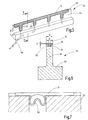
- FIG. 5 shows the variant of a cutting electrode carrier 22 made of ceramic.
- the wall-like extension 24 has on its front side a groove 55 in which the strip-like cutting electrode 31 is seated.
- This preferably has a plurality of attachment extensions 56, 57, which extend through openings of the cutting electrode carrier 22.
- the electrode assembly formed in this way can be glued from a cutting electrode carrier 22 formed with ceramic.
- one or more attachment extensions 56, 57 may be connected to an electrical lead 58 which serves to supply power to the cutting electrode 31.
- the cutting electrode carrier 22 effects a potential separation between the cutting electrode 31 and the sealing electrodes 25, 26, 39, 40.
- the sealing electrodes 39 and 40 serve as neutral electrodes
- the sealing electrodes 25, 26 are subjected to a sealing effecting voltage , which is preferably less than the intended for cutting the tissue, the cutting electrode 31 fed voltage.
- the sealing electrodes 25, 26, 39, 40 preferably have a total electrode area which is greater than ten times, preferably greater than twenty times, the area of the end face 32, so that the energy supply is cut only at the end face 32, at the sealing electrodes 25, 26, 39, 40 but causes no separation of the tissue.
- FIG. 7 illustrates a modified embodiment of the cutting electrode carrier 22.
- the cutting electrode 31 in turn sits in a groove of the cutting electrode carrier and is anchored there with resilient feet 59.
- the main body of the cutting electrode body 22 may be made of ceramic or plastic.
- the plastic is a thermoset or a silicone, which is in particular high-temperature stable, flame retardant and stable against spark erosion, and has a CTI greater than 600. In addition, it should have a sufficiently high mechanical strength and a thermal conductivity greater than one W / mK.
- Such a plastic can in particular with an electrode inlay 60 after FIG. 8 be provided.
- the cutting electrode 31 can here as in all other embodiments of a sheet, for example made of stainless steel exist.
- the numerous windows present in the electrode inlay 60 achieve an intimate connection of plastic and electrode inlay 60 and a low heat input into the plastic.
- a surgical instrument 10 provided in particular for filigree work has two branches 15, 16 with sealing jaws 19, 20, 36, 37, which can be acted upon with a sealing voltage preferably between 80 and 120 volts. Between the branches 15, 16 tissue receiving spaces 53, 54 are defined, which are of a wall-like Extension 24 are separated from each other, which carries a cutting electrode 31 at its lower edge. Between a branch 16 and the cutting electrode is a cutting voltage of 300 to 500 volts. When closing the branches, the collected tissue is simultaneously sealed between the sealing jaws 19, 36 and 20, 37 and severed by the cutting electrode 31. For example, even if the tissue is completely severed after 0.3 to 0.5 seconds and the sealant requires additional time, approximately 1.5 to 3.5 seconds in total, vessel separation with closed, sealed vessel ends can be achieved.
- the tissue receiving chambers 53, 54 act as a form-fitting securing of the already separated vessel ends and thus ensure the formation of closed vessel ends with tissue cavities in the tool 12.
- the vessel ends are weaker or non-coagulated compared to the sealing zone, thus forming bead-like thickenings which prevent the tissue sacs from escaping when the instrument is closed.
Landscapes
- Health & Medical Sciences (AREA)
- Surgery (AREA)
- Engineering & Computer Science (AREA)
- Life Sciences & Earth Sciences (AREA)
- Biomedical Technology (AREA)
- Otolaryngology (AREA)
- Nuclear Medicine, Radiotherapy & Molecular Imaging (AREA)
- Plasma & Fusion (AREA)
- Physics & Mathematics (AREA)
- Heart & Thoracic Surgery (AREA)
- Medical Informatics (AREA)
- Molecular Biology (AREA)
- Animal Behavior & Ethology (AREA)
- General Health & Medical Sciences (AREA)
- Public Health (AREA)
- Veterinary Medicine (AREA)
- Surgical Instruments (AREA)
Abstract
Ein insbesondere für filigrane Arbeiten vorgesehenes Versiegelungsinstrument (10) weist zwei Branchen (15, 16) mit Versiegelungsbacken (19, 20, 36, 37) auf, die mit einer Versiegelungsspannung vorzugsweise zwischen 80 und 120 Volt beaufschlagbar sind. Zwischen den Branchen (15, 16) sind Gewebeaufnahmeräume (53, 54) definiert, die von einem wandartigen Fortsatz (24) voneinander getrennt sind, der an seiner unteren Kante eine Schneidelektrode (31) trägt. Zwischen einer Branche (16) und der Schneidelektrode liegt eine Schneidspannung von 300 bis 500 Volt an. Beim Schließen der Branchen wird das gefasste Gewebe gleichzeitig zwischen den Versiegelungsbacken (19, 36 sowie 20, 37) versiegelt und von der Schneidelektrode (31) durchtrennt. Selbst wenn das Gewebe beispielsweise nach 0,3 bis 0,5 Sekunden vollständig durchtrennt ist und die Versiegelung weitere Zeit, insgesamt etwa 1,5 bis 3,5 Sekunden benötigt, wirken die in den Gewebeaufnahmeräumen (53, 54) gefassten Gewebewülste als formschlüssige Sicherung der Gewebesäume in dem Werkzeug (12).A sealing instrument (10) provided in particular for filigree work has two branches (15, 16) with sealing jaws (19, 20, 36, 37), which can be acted upon with a sealing voltage preferably between 80 and 120 volts. Between the branches (15, 16) tissue receiving spaces (53, 54) are defined, which are separated from each other by a wall-like extension (24), which carries at its lower edge a cutting electrode (31). Between a branch (16) and the cutting electrode is a cutting voltage of 300 to 500 volts. When closing the branches, the collected tissue is simultaneously sealed between the sealing jaws (19, 36 and 20, 37) and severed by the cutting electrode (31). For example, even if the tissue is completely severed after 0.3 to 0.5 seconds and the sealant requires additional time, a total of about 1.5 to 3.5 seconds, the tissue bulges captured in the tissue containment spaces (53, 54) act as a positive fit the fabric seams in the tool (12).
Description
Die Erfindung betrifft ein chirurgisches Instrument zur Versiegelung und Trennung von biologischem Gewebe.The invention relates to a surgical instrument for sealing and separating biological tissue.
Versiegelungsinstrumente der genannten Art sind zur Operation an lebenden menschlichen oder tierischen Patienten in Gebrauch. Sie dienen zur Erfassung und Versiegelung von Gewebe unter Einfluss von Druck und Stromdurchfluss sowie darauf beruhender Wärme. Außerdem können solche Instrumente zum Durchtrennen von koaguliertem bzw. versiegeltem Gewebe dienen.Sealing instruments of the type mentioned are in use for operation on living human or animal patients. They are used to detect and seal tissue under the influence of pressure and current flow and heat based on it. In addition, such instruments may serve to sever coagulated or sealed tissue.
Die
Zur Versiegelung des Gefäßes weisen die beiden Branchen des Werkzeugs ebene Kontaktflächen auf, zwischen denen das Gefäß versiegelt wird. Die Kontaktflächen müssen eine erhebliche Mindestbreite aufweisen, um ein sicheres Versiegeln des Gefäßes zu erreichen. Deswegen sind der Miniaturisierung solcher Werkzeuge Grenzen gesetzt.To seal the vessel, the two branches of the tool have flat contact surfaces, between which the vessel is sealed. The contact surfaces must have a considerable minimum width in order to achieve a secure sealing of the vessel. That's why there are limits to the miniaturization of such tools.
Weiter ist aus der
Bei einem solchen Instrument ist eine federnde Klemmung der Gefäßenden während der Koagulation möglich. Dennoch sind auch hier der Miniaturisierung Grenzen gesetzt.In such an instrument, a resilient clamping of the vessel ends during coagulation is possible. Nevertheless, there are limits to miniaturization.
Die
Aus der
Es ist Aufgabe der Erfindung, ein Versiegelungsinstrument anzugeben, dessen Konzept eine Miniaturisierung des Werkzeugs gestattet.It is an object of the invention to provide a sealing instrument whose concept allows for miniaturization of the tool.
Diese Aufgabe wird mit dem Versiegelungsinstrument nach Anspruch 1 und mit einem Verfahren nach Anspruch 15 gelöst:This object is achieved with the sealing instrument according to claim 1 and with a method according to claim 15:
Das erfindungsgemäße Versiegelungsinstrument für den endoskopischen, laparaskopischen oder offen chirurgischen Anwendungsbereich weist zwei Branchen auf. Die erste Branche weist mindestens zwei Versiegelungselektroden auf, die vorzugsweise miteinander elektrisch verbunden sind. Die zweite Branche weist ebenfalls mindestens zwei Versiegelungselektroden auf, die vorzugsweise miteinander elektrisch verbunden sind. Eine der Branchen (z.B. die obere) weist einen Schneidelektrodenträger mit einem wand- oder schneidenartigen Fortsatz auf. Die andere Branche weist ein entsprechendes Gegenlager für die Schneidelektrode auf. An den Rändern der beiden Branchen sind Versiegelungselektroden angebracht, um Versiegelungssäume am biologischen Gewebe zu erzeugen. Zwischen der Schneidelektrode und den Versiegelungsbacken sind Gewebeaufnahmeräume ausgebildet. Diese weisen vorzugsweise ein solches Volumen auf, dass die dort auftretende Stromdichte deutlich geringer ist, als zwischen den Versiegelungsbacken. Das zwischen Schneidelektrode und den Versiegelungsbacken gefasste, also in den Gewebeaufnahmeräumen befindliche Gewebe wird elektrisch durchströmt, schrumpft dabei aber weniger als das zwischen den Backen zur Ausbildung eines Versiegelungssaums gefasste Gewebe. Das Gewebe bildet wenigstens eine Wulst, die bei geschlossenen Branchen sowohl den ersten Versiegelungsbacken als auch den zweiten Versieglungsbacken annähernd formschlüssig hintergreift. Der Gewebeaufnahmeraum und das in ihm gefasste Gewebe wirken somit als formschlüssige Sicherung für das zwischen den Versiegelungsbacken gefasste Gewebe auch dann, wenn nur ein sehr schmaler Versiegelungssaum und ein sehr filigraner Gewebewulst ausgebildet wird. Das Gewebe kann nicht vor dem Öffnen des Werkzeugs aus dem Versiegelungsinstrument herausrutschen.The sealing instrument according to the invention for The endoscopic, laparoscopic or open surgical application has two branches. The first industry has at least two sealing electrodes, which are preferably electrically connected to each other. The second branch likewise has at least two sealing electrodes, which are preferably electrically connected to one another. One of the sectors (eg the upper one) has a cutting electrode carrier with a wall or cutting-like extension. The other industry has a corresponding counter bearing for the cutting electrode. At the edges of the two sectors, sealing electrodes are applied to create sealing seams on the biological tissue. Tissue receiving spaces are formed between the cutting electrode and the sealing jaws. These preferably have such a volume that the current density occurring there is significantly lower than between the sealing jaws. The tissue gripped between the cutting electrode and the sealing jaws, that is to say located in the tissue receiving chambers, is flowed through electrically, but shrinks less than the tissue grasped between the jaws to form a sealing seam. The fabric forms at least one bead, which engages approximately positively with closed sectors both the first sealing jaws and the second sealing jaws. The tissue receiving space and the tissue held in it thus act as a positive securing for the captured between the sealing jaws tissue even if only a very narrow sealing seam and a very filigree tissue bulge is formed. The tissue can not slip out of the sealing instrument prior to opening the tool.
Dieses Konzept eröffnet auch die Möglichkeit, mit einer Schneidelektrode zu arbeiten, die zeitgleich mit den Versiegelungselektroden aktiviert wird und somit der Koagulationsprozess und der Schneideprozess zeitgleich beginnt. Das Gewebe kann von der Schneidelektrode durchtrennt werden, bevor die Versiegelung zwischen den Versiegelungsbacken abgeschlossen ist. Die gleichzeitige Einwirkung von Schneidelektrode und Versiegelungsbacken auf das Gewebe ist nicht zwingend, aber möglich. Die zeitliche Abfolge von Schnitt und Versiegelung stellt sich vorzugsweise durch die an der Schneidelektrode und an den Versiegelungsbacken angelegten Spannungen von selbst ein. Es kann dadurch eine Verkürzung der Versiegelungs- und Trennzeit sowie eine Vereinfachung des Arbeitsablaufs und der elektrischen Bestromung des Instruments erreicht werden. Z.B. können eine Versiegelungsspannung (z.B. 97 V) zwischen den Versiegelungsbacken und eine Schneidspannung (z.B. 437 V) zwischen einem Versiegelungsbacken und der Schneidelektrode aus einer Speiseschaltung gleichzeitig angelegt werden. Die Spannungen können aus einem Spartrafo geliefert werden. Die Bestromung kann zunächst mit einem rampenförmigen Stromverlauf und dann mit konstanter Spannung erfolgen. Die Behandlung kann außerdem zeitgesteuert erfolgen. Es kann eine Mindestzeit von 1,4 s und/oder eine Maximalzeit von z.B. 2,8 s festgelegt sein. Als Abschaltkriterium in dem so festgelegten Zeitfenster kann festgelegt sein, dass abgeschaltet wird, wenn nach dem erstem Abfall des Gewebewiderstands ein Wiederanstieg desselben festgestellt wird, wonach gegebenenfalls noch eine zeitliche Zugabe der Bestromung von z.B. 0,4 s erfolgt. Außerdem kann das Instrument oder sein speisendes Gerät mit einer Überspannungs- und Funkenerkennungseinrichtung versehen sein. Zum Löschen erkannter Funken kann eine kurzzeitige Spannungsabsenkung vorgenommen werden.This concept also opens up the possibility of working with a cutting electrode that is activated simultaneously with the sealing electrodes and thus the coagulation process and the cutting process starts at the same time. The tissue may be severed by the cutting electrode before the seal between the sealing jaws is completed. The simultaneous action of cutting electrode and sealing jaws on the tissue is not mandatory, but possible. The timing of cut and seal preferably adjusts itself by the voltages applied to the cutting electrode and the sealing jaws. It can thereby be achieved a shortening of the sealing and separation time and a simplification of the workflow and the electrical current supply of the instrument. For example, a sealing voltage (eg, 97V) may be applied between the sealing jaws and a cutting voltage (eg, 437V) between a sealing jaw and the cutting electrode of a feed circuit simultaneously. The voltages can be supplied from a power transformer. The current supply can first be carried out with a ramp-shaped current profile and then with a constant voltage. The treatment can also be timed. It can be set a minimum time of 1.4 s and / or a maximum time of, for example, 2.8 s. As a switch-off criterion in the time window thus determined, it can be determined that switching off occurs when, after the first drop in tissue resistance, a recovery thereof is detected, after which, if appropriate, there is a time addition of the current supply of, for example, 0.4 s. In addition, the instrument or its feeding device may be provided with an overvoltage and spark detection device. To erase detected sparks, a short-term voltage reduction can be made.
Außerdem ist das genannte Konzept miniaturisierungsfähig. Durch die formschlüssige Sicherung der Gefäß- oder Gewebeenden in den Gewebeaufnahmeräumen lassen sich die Versiegelungszonen auf sehr schmale, fast linienartige Streifen begrenzen, ohne dass zu befürchten wäre, dass unversiegelte Gewebekanten dem Versiegelungsinstrument vorzeitig entkommen.In addition, the said concept is capable of miniaturization. By the positive securing of the vascular or tissue ends in the tissue receiving spaces can be limit the sealing zones to very narrow, almost line-like strips without fear of unsealed edges of tissue escaping prematurely from the sealing instrument.
Die Gewebeaufnahmeräume, die zu beiden Seiten der Schneidelektrode ausgebildet sind, weisen eine Form auf, wodurch ein besonders guter Formschluss zwischen Gewebe und geschlossenem Instrument erreicht wird. Vorzugsweise ist außerdem die Breite der Gewebeaufnahmeräume größer als die Breite des wandartigen Fortsatzes, der die Schneidelektrode trägt. Außerdem ist die Breite der Gewebeaufnahmeräume vorzugsweise größer als die Breite der Versiegelungsbacken. Auch dies trägt zu einem sicheren Formschluss und zu einer ausreichenden Verminderung der Stromdichte innerhalb des im Aufnahmeraum befindlichen Gewebes bei.The tissue receiving spaces, which are formed on both sides of the cutting electrode, have a shape, whereby a particularly good fit between tissue and closed instrument is achieved. Preferably, moreover, the width of the tissue receiving spaces is greater than the width of the wall-like extension supporting the cutting electrode. In addition, the width of the tissue receiving spaces is preferably greater than the width of the sealing jaws. This also contributes to a positive fit and to a sufficient reduction of the current density within the tissue located in the receiving space.
Die Versiegelungsbacken weisen vorzugsweise eine Querschnittskontur mit gerundeten Übergängen auf. Insbesondere sind die Versiegelungsbacken zu den Gewebeaufnahmeräumen hin gerundet, wodurch eine Stromkonzentration vermieden wird. Dabei sind diese Rundungen so gestaltet, dass außer der geringeren Stromkonzentration ein sicherer Formschluss zwischen Gewebe und geschlossenen Branchen möglich ist. Vorzugsweise legen die Versiegelungsbacken der beiden Branchen miteinander Versiegelungsspalte fest, die miteinander einen stumpfen Winkel definieren. Dadurch kann die Rundung der Versiegelungsbacken, die der Schneidelektrode am nächsten liegen, einen großen Rundungsradius erhalten, wodurch gerade hier die Stromdichte begrenzt wird. Ist die Schneideelektrode in der oberen Branche befestigt, können die Rundungsradien der unteren Branche, die in Richtung der Gewebeaufnahmeräume angeordnet sind, einen anderen Wert als die Rundungsradien der oberen Branche umfassen. Vorzugsweise weisen diese Radien jedoch die gleichen Werte auf. Die Rundungsradien der Versiegelungsbacken an der Branchenaußenseite, weisen größere Werte auf, als die Rundungsradien in Richtung der Gewebeaufnahmeräume. Dadurch kann der Gewebeeffekt außerhalb der Branchen besser kontrolliert werden. Durch die Schrägstellung der Versiegelungsspalte ergibt sich eine selbsttätige Zentrierung der Branchen zueinander. Außerdem haben die Versiegelungsbacken an ihren Klemmflächen Radien in Richtung der Gewebeaufnahmeräume von z.B. 0,05 mm bis 0,1 mm um einen guten Formschluss zwischen Gewebe und Instrument zu erreichen und Radien an der Branchenaußenseite von z.B. 0,1 mm bis 0,3 mm um gute Versiegelungseigenschaften zu erzielen. Die Klemmflächen legen miteinander einen Versiegelungs- bzw. Klemmspalt von 0 bis 0,1 mm vorzugsweise 0 bis 0,05 mm fest, was ein sicheres Klemmen auch von dünnem Gewebe gestattet.The sealing jaws preferably have a cross-sectional contour with rounded transitions. In particular, the sealing jaws are rounded toward the tissue receiving spaces, thereby avoiding current concentration. These curves are designed so that in addition to the lower power concentration, a secure fit between tissue and closed branches is possible. Preferably, the sealing jaws of the two branches define sealing gaps with each other which define an obtuse angle with each other. As a result, the rounding of the sealing jaws closest to the cutting electrode can be given a large radius of curvature, which limits the current density in this case. If the cutting electrode is mounted in the upper branch, the radii of curvature of the lower branch, which are arranged in the direction of the tissue receiving chambers, may have a value different from the rounding radii of the upper branch. However, these radii preferably have the same values. The Rounding radii of the sealing jaws on the outside of the sector have greater values than the radii of curvature in the direction of the tissue receiving spaces. This allows better control of the tissue effect outside of the branches. Due to the inclination of the sealing gaps results in an automatic centering of the branches to each other. In addition, the sealing jaws have at their clamping surfaces radii in the direction of the tissue receiving spaces of eg 0.05 mm to 0.1 mm to achieve a good fit between tissue and instrument and radiuses on the outside of the industry, for example, 0.1 mm to 0.3 mm to achieve good sealing properties. The clamping surfaces define together a sealing or nip of 0 to 0.1 mm, preferably 0 to 0.05 mm, which allows a secure clamping even of thin tissue.
Die Versiegelungsbacken weisen einen Grundkörper mit isolierenden Bereichen z.B. aus Epoxidharz mit in einer Reihe angeordneten Versiegelungselektroden z.B. aus dem Material des Grundkörpers der Branche, z.B. Edelstahl auf. Der Grundkörper der Branchen kann aus einem Vollmaterial oder einem Stanz- / Biegeteil gebildet sein. Die Elektroden gegenüberliegender Versiegelungsbacken sind vorzugsweise einander nicht überlappend angeordnet bzw. ausgebildet. Die isolierenden Bereiche können durch in die Branchen eingesetzte oder eingeformte (gegossene oder gespritzte) Einlagen oder durch eine Anzahl lokaler Beschichtungen aus Isolationsmaterial gebildet sein. Alternativ kann eine Branche aus Keramik gebildet sein, wobei sie dann im Bereich der Versiegelungselektroden leitend beispielsweise metallisiert ausgebildet ist. Auch ist es möglich, die Branche aus Keramiken mit unterschiedlichen Eigenschaften auszubilden. So kann die Branche beispielsweise ausschließlich aus Keramik gebildet sein, wobei sie dann für die isolierenden Bereiche eine nicht leitende Keramiksubstanz und für den Elektrodenbereich eine leitende Keramiksubstanz aufweist. Die isolierenden Bereiche verhindern einen elektrischen Kurzschluss zwischen den Versiegelungselektroden der beiden Versiegelungsbacken auch dann, wenn sich die Branchen berühren. Der wechselweise Längs-Abstand zwischen Elektroden der beiden Branchen ist 0,1 mm bis 0,3 mm vorzugsweise 0,25 mm. Außerdem ergibt sich in dem biologischen Gewebe ein Stromfluss mit einer Komponente längs der Versiegelungsbacken, d.h. eine Verlängerung der Strompfade mit einer Verbesserung der thermisch biologischen Wirkung. Außerdem können die Versiegelungsbacken an ihren den Gewebeaufnahmeräumen zugewandten Seiten mit nichtmetallischem Material, z.B. PTFE, Kunstharz oder dergleichen versehen sein. Der Stromfluss des Schneidstroms wird so einerseits auf die Schneidelektrode und andererseits auf den zwischen den Versiegelungsbacken gefassten Gewebebereich konzentriert. Die Gefahr des Anklebens des Gewebes in den Gewebeaufnahmeräumen ist beseitigt bzw. deutlich minimiert.The sealing jaws have a basic body with insulating regions, for example of epoxy resin, with sealing electrodes arranged in a row, for example, of the material of the main body of the industry, eg, stainless steel. The main body of the branches may be formed of a solid material or a stamped / bent part. The electrodes of opposing sealing jaws are preferably arranged or formed so as not to overlap one another. The insulating regions may be formed by inserts (molded or molded) inserted or molded into the industries, or by a number of local coatings of insulating material. Alternatively, an industry may be formed of ceramic, wherein it is then made conductive metallized, for example, in the region of the sealing electrodes. It is also possible to develop the industry from ceramics with different properties. For example, the industry may be formed solely of ceramic, and then for the insulating regions, a non-conductive ceramic substance and for the electrode area a conductive ceramic substance. The insulating regions prevent electrical shorting between the sealing electrodes of the two sealing jaws, even when the sectors touch. The alternate longitudinal distance between electrodes of the two branches is 0.1 mm to 0.3 mm, preferably 0.25 mm. In addition, in the biological tissue results in a flow of current with a component along the sealing jaws, ie an extension of the current paths with an improvement in the thermal biological effect. In addition, the sealing jaws may be provided with non-metallic material such as PTFE, synthetic resin or the like on their sides facing the tissue receiving spaces. The current flow of the cutting current is thus concentrated on the one hand on the cutting electrode and on the other hand on the captured between the sealing jaws tissue area. The risk of sticking of the tissue in the tissue receiving spaces is eliminated or significantly minimized.
Der Schneidelektrodenträger kann aus Keramik, Kunststoff oder einem isolationsbeschichteten Metall ausgebildet sein. Zusätzlich kann der Schneidelektrodenträger eine Oberfläche aufweisen, an der Gewebe nicht haftet. Dazu kann die Oberfläche des Schneidelektrodenträger antihaftend ausgebildet beispielsweise beschichtet sein. Zusätzlich weist der Schneidelektrodenträger eine hohe Kriechstromfestigkeit beziehungsweise einen hohen CTI (Comparative Tracking Index) Wert, vorzugsweise größer 600 auf. Die Schneidelektrode ist vorzugsweise als dünne Leiste ausgeführt, die eine freiliegende Stirnfläche aufweist trägt und über geeignete Mittel, beispielsweise mehrere Füße, in oder an dem Elektrodenträger verankert ist. Auf diese Weise wird die thermische Trägheit der Schneidelektrode auf ein Minimum begrenzt. Das Gegenlager kann federnd angeordnet sein, um ein Zerquetschen des Gewebes zu verhindern und den Schnitt durch elektrische Einwirkung zu führen. Dies kommt der Versiegelungssicherheit zugute, da auf diese Art und Weise, eine Bewegung aufgrund des Gewebeschneidens, zwischen Schneidelektrode der einen und Gegenlager der anderen Branche, nicht in gleichem Ausmaß eine Branchenbewegung und damit eine Bewegung zwischen gegenüberliegenden Versiegelungsbacken bewirkt. Alternativ oder zusätzlich kann der Schneidelektrodenträger federnd gelagert sein. In diesem Fall kann das Gegenlager starr befestigt sein.The cutting electrode carrier can be made of ceramic, plastic or an insulation-coated metal. In addition, the cutting electrode carrier may have a surface to which tissue does not adhere. For this purpose, the surface of the cutting electrode carrier can be coated, for example, coated in an anti-adhesive manner. In addition, the cutting electrode carrier has a high tracking resistance or a high CTI (Comparative Tracking Index) value, preferably greater than 600. The cutting electrode is preferably designed as a thin strip, which has an exposed end face carries and is anchored by suitable means, for example a plurality of feet, in or on the electrode carrier. In this way, the thermal inertia of the cutting electrode is kept to a minimum. The anvil may be resiliently arranged to prevent crushing of the tissue and the Cut by electrical action to lead. This benefits the sealing security, since in this way, a movement due to the tissue cutting, between the cutting electrode of the one and counter-bearing of the other industry, not to the same extent causes a branch movement and thus a movement between opposing sealing jaws. Alternatively or additionally, the cutting electrode carrier may be spring-mounted. In this case, the anvil can be rigidly attached.
Ist der Schneidelektrodenträger aus Kunststoff ausgebildet, wird die Schneidelektrode vorzugsweise mit Kunststoff umspritzt. Die Schneidelektrode kann z.B. aus Edelstahlblech bestehen. Die Breite der Schneidelektrode beträgt vorzugsweise etwa 0,1 mm. Die Dicke des Kunststoffs zu beiden Seiten der Schneidelektrode beträgt vorzugsweise etwa 0,15 mm. Die Schneidelektrode schließt vorzugsweise mit den beiden, ihre Flanken bedeckenden Kunststoffwänden bündig ab (kein Schneidenüberstand). Als Kunststoff wird vorzugsweise ein Duroplast eingesetzt. Alternativ kann die Schneidelektrode im ungenutzten Zustand die Kunststoffwände geringfügig, beispielsweise um 0,02 mm bis 0,04 mm überragen. Der Überstand kann sich während des Betreibens des Instrumentes, beispielsweise durch Abbrand der Schneidelektrodenträgers, verändern.If the cutting electrode carrier is made of plastic, the cutting electrode is preferably encapsulated with plastic. The cutting electrode may e.g. Made of stainless steel sheet. The width of the cutting electrode is preferably about 0.1 mm. The thickness of the plastic on both sides of the cutting electrode is preferably about 0.15 mm. The cutting electrode preferably ends flush with the two plastic walls covering its flanks (no cutting overhang). As plastic, a thermoset is preferably used. Alternatively, the cutting electrode in the unused state, the plastic walls slightly, for example by 0.02 mm to 0.04 mm surmount. The supernatant may change during operation of the instrument, for example as a result of burning of the cutting electrode carrier.
Ist der Schneidelektrodenträger aus Keramik, vorzugsweise ZrO2-Keramik gefertigt, werden der Schneidelektrodenträger und die Schneidelektrode getrennt vorgefertigt und dann zusammengefügt. Die Breite der Schneidelektrode beträgt vorzugsweise 0,2 bis 0,25 mm. Sie kann aus einem Blech, insbesondere Edelstahlblech bestehen. Die isolierenden Wände zu beiden Seiten der Schneidelektrode haben vorzugsweise eine Dicke von 0,15 mm. Vorzugsweise ist ein Schneidenüberstand von 0,02 mm bis 0,04 mm festgelegt. Die Schneidelektrode kann mit dem Schneidelektrodenträger formschlüssig verbunden, verklemmt oder stoffschlüssig verklebt werden. Typischerweise existiert ein Spalt zwischen der Schneidelektrode und den dünnen isolierenden Wänden des Schneidelektrodenträgers. Dieser Spalt kann mit Klebstoff, Silikon oder ähnlichem gefüllt werden. Alternativ kann die Schneidelektrode eine seitliche Isolation aufweisen, z.B. aus einem Lack oder einer Beschichtung z.B. Parylene. Dadurch wird die seitliche Kontaktfläche der Schneidelektrode isoliert und der Einfluss eines im Spalt zwischen Schneidelektrode und Schneidelektrodenträger befindlichen Fluid auf die Schneidwirkung der Schneidelektrode minimiert vorzugsweise verhindert.If the cutting electrode carrier is made of ceramic, preferably ZrO 2 ceramic, the cutting electrode carrier and the cutting electrode are prefabricated separately and then joined together. The width of the cutting electrode is preferably 0.2 to 0.25 mm. It can consist of a sheet metal, in particular stainless steel sheet. The insulating walls on both sides of the cutting electrode preferably have a thickness of 0.15 mm. Preferably, a Cutting edge defined from 0.02 mm to 0.04 mm. The cutting electrode can be positively connected to the cutting electrode carrier, clamped or adhesively bonded. Typically, there is a gap between the cutting electrode and the thin insulating walls of the cutting electrode carrier. This gap can be filled with glue, silicone or similar. Alternatively, the cutting electrode may have a lateral insulation, for example of a paint or a coating such as parylene. As a result, the lateral contact surface of the cutting electrode is isolated and the influence of a fluid located in the gap between the cutting electrode and the cutting electrode carrier on the cutting action of the cutting electrode is minimized and preferably prevented.
Das der Schneidelektrode gegenüberliegend angeordnete Gegenlager ist vorzugsweise federnd gelagert. Der Federhub kann auf weniger als 1mm, vorzugsweise 0,5 mm festgelegt sein. Das Gegenlager dient der Aufrechterhaltung der Klemmkraft zwischen den Versiegelungsbacken. Erreicht wird dies durch die mechanische Entkopplung der Gewebeklemmung im Bereich der Versiegelungsbacken von der Gewebeklemmung zwischen Schneidelektrode und Gegenlager. Damit werden auch die Schrumpfungen des Gewebes beim Schnitt und beim Versiegeln von der Klemmkraft zwischen den Versiegelungsbacken entkoppelt. Diese Wirkung tritt auch bei Ausführungsformen mit starr angeordnetem Gegenlager und federnd gelagerter Schneidelektrode auf.The counter electrode of the cutting electrode arranged opposite is preferably spring-mounted. The spring stroke can be set to less than 1mm, preferably 0.5 mm. The anvil serves to maintain the clamping force between the sealing jaws. This is achieved by the mechanical decoupling of the tissue clamping in the area of the sealing jaws from the tissue clamping between the cutting electrode and the abutment. Thus, the shrinkage of the fabric during cutting and sealing are decoupled from the clamping force between the sealing jaws. This effect also occurs in embodiments with rigidly arranged abutment and spring-mounted cutting electrode.
Die Oberseite bzw. Gewebeauflagefläche des Gegenlagers sitzt bei geschlossenen Branchen auf einer anderen Ebene als die Versiegelungsbacken. Die Schneideebene der Schneidelektrode steht über die Versiegelungsbacken der an derselben Brache angeordneten Versiegelungselektroden hinaus. Damit findet der Schneidprozess auf einer anderen Ebene statt als der Versiegelungsprozess.The top or tissue support surface of the anvil sits in closed branches on a different level than the sealing jaws. The cutting plane of the cutting electrode protrudes beyond the sealing jaws of the sealing electrodes disposed on the same bank. Thus, the cutting process takes place on a different level than the sealing process.
Im geöffneten Zustand der Branchen kann das Gegenlager die Versiegelungsbacken derselben Branche überragen. Beim Schließen der Branchen wird dann das federelastische oder federelastisch gelagerte Gegenlager komprimiert und dabei in die Branche gedrückt. Dadurch entsteht die Federkraft, die dem Schneidelement entgegenwirkt.When the branches are open, the counter bearing can surpass the sealing jaws of the same industry. When closing the branches, the spring-elastic or spring-loaded counter bearing is then compressed and pressed into the industry. This creates the spring force that counteracts the cutting element.
Das Gegenlager besteht vorzugsweise aus einem Isolator mit Antihaftoberfläche, z.B. aus PTFE, und ähnlichen oder gleichen Kriechstromeigenschaften wie der Schneidelektrodenträger. Die federnde Lagerung des Gegenlagers ergibt ein Schnittverhalten, bei dem sich der Schneidspalt an die Gewebeschrumpfung beim Schnitt anpasst. Das längliche Gegenlager kann an seinem proximalen Ende unabhängig von seinem distalen Ende federn und so mit der Schneidelektrode auch einen keilförmigen Spalt festlegen, wenn längs der Schneidelektrode unterschiedliche Gewebedicken vorliegen.The anvil preferably consists of an insulator with non-stick surface, e.g. made of PTFE, and similar or the same creepage characteristics as the cutting electrode carrier. The resilient mounting of the anvil results in a cutting behavior in which the cutting gap adapts to the tissue shrinkage during the cut. The elongated anvil can spring independently of its distal end at its proximal end and thus also define a wedge-shaped gap with the cutting electrode if different tissue thicknesses are present along the cutting electrode.
Es ist alternativ möglich, das Schneidelement federnd zu lagern. Das Gegenlager kann in diesem Fall starr oder ebenfalls federnd beweglich gelagert werden. Es ist auch möglich, eines der Elemente um eine Querachse schwenkbar und das jeweils andere Element federnd zu lagern, um z.B. bei besonders kleinem Federhub von z.B. weniger als 0,5 mm eine gute Anpassung der Schneidelektrode und des Gegenlagers an unterschiedliche Gewebestärken entlang der Schneidelektrode zu erreichen.It is alternatively possible to store the cutting element resiliently. The anvil can be mounted rigidly or also resiliently movable in this case. It is also possible to pivot one of the elements about a transverse axis and resiliently support the other element, e.g. with a particularly small spring stroke of e.g. Less than 0.5 mm to achieve a good adaptation of the cutting electrode and the abutment to different tissue strengths along the cutting electrode.
Das erfindungsgemäße Verfahren zur Versiegelung und Trennung von Gewebe umfasst vorzugsweise mindestens die folgenden Schritte:
- Zwischen zwei Branchen wird Gewebe so gefasst, dass es zwischen Versiegelungsbacken sowie zwischen der Schneidelektrode und der Gewebeauflagefläche geklemmt wird, wobei zwischen den geschlossenen Versiegelungsbacken und einem Schneidelektrodenträger Gewebeaufnahmeräume ausgebildet sind, die wenigstens teilweise von Teilen des Gewebes gefüllt werden, und die Energiezufuhr zu den Versiegelungsbacken und der Schneidelektrode findet gleichzeitig statt.
- Tissue is captured between two branches so that it is clamped between sealing jaws as well as between the cutting electrode and the tissue support surface with tissue receiving spaces between the closed sealing jaws and a cutting electrode carrier at least partially filled by portions of the tissue and the energy input to the sealing jaws and the cutting electrode takes place simultaneously.
Durch die gleichzeitige Energiezufuhr an die Versiegelungselektroden und der Schneidelektrode finden die Prozesse Gefäße versiegeln und Gefäße trennen (schneiden) gleichzeitig statt. Das Trennen von Gefäßen kann beendet sein, bevor das Versiegeln der Gefäße endet. Die Gewebeaufnahmeräume sichern während des Prozesses der Gefäßversiegelung die Gewebesäume innerhalb der Branchen bis zur vollständigen Beendigung des Versiegelungsprozesses. Durch die erfindungsgemäße Ausbildung der Branchen in Verbindung mit der erfindungsgemäßen Art und Weise der Energiezufuhr kann das Bearbeiten, insbesondere das Trennen und das Versiegeln von Gefäßen in höchster Qualität erfolgen. Der gesamte Bearbeitungsvorgang ist wegen des zeitgleichen Starts von Versiegelung und Schneiden insgesamt kurz und dauert im Allgemeinen nicht länger als die Versiegelung für sich alleine.By simultaneously supplying energy to the sealing electrodes and the cutting electrode, the processes are sealing vessels and separating (cutting) vessels at the same time. The separation of vessels may be completed before the sealing of the vessels ends. The tissue containment spaces, during the process of vessel sealing, secure the tissue spaces within the branches until the completion of the sealing process. Due to the inventive construction of the industries in conjunction with the manner of the invention of the energy supply processing, in particular the separation and sealing of vessels can be done in the highest quality. The entire machining process is short overall because of the simultaneous start of sealing and cutting, and generally takes no longer than the seal on its own.
Weitere Einzelheiten vorteilhafter Ausführungsformen der Erfindung ergeben sich aus der Zeichnung der Beschreibung oder Ansprüchen. Es zeigen:
-
Figur 1 ein Versiegelungsinstrument in schematisierter perspektivischer Gesamtdarstellung; -
Figur 2 das Werkzeug des Versiegelungsinstruments nachFigur 1 in vergrößerter perspektivischer teilweise geschnittener Darstellung; -
Figur 3 das Werkzeug nachFigur 2 in geschlossenem Zustand in Querschnittsdarstellung; -
Figur 4 das Werkzeug nachFigur 3 beim Versiegeln und Trennen eines Hohlgefäßes; -
Figur 5 die Schneidelektrode des Werkzeugs nachFigur 2 in einer perspektivischen teilweise geschnittenen Darstellung in einer ersten Ausführungsform; -
Figur 6 die Schneidelektrode nachFigur 5 in Querschnittsdarstellung; -
Figur 7 eine abgewandelte Ausführungsform einer Schneidelektrode und eines Schneidelektrodenträgers in Längsschnittdarstellung; und -
Figur 8 eine weitere abgewandelte Ausführungsform einer Schneidelektrode in perspektivischer Darstellung.
-
FIG. 1 a sealing instrument in a schematic perspective overall representation; -
FIG. 2 the tool of the sealing instrumentFIG. 1 in an enlarged perspective partially cut representation; -
FIG. 3 the tool afterFIG. 2 in closed state in cross-sectional view; -
FIG. 4 the tool afterFIG. 3 when sealing and separating a hollow vessel; -
FIG. 5 the cutting electrode of the toolFIG. 2 in a perspective partially sectioned view in a first embodiment; -
FIG. 6 the cutting electrode afterFIG. 5 in cross-sectional view; -
FIG. 7 a modified embodiment of a cutting electrode and a cutting electrode carrier in a longitudinal sectional view; and -
FIG. 8 a further modified embodiment of a cutting electrode in a perspective view.
In
Das an dem Instrument 10 vorgesehene Werkzeug 12 ist auf besondere Weise ausgebildet. Es weist eine erste Branche 15, in
Die Branchen 15, 16 sind in den
Der Schneidelektrodenträger 22 weist eine Schneidelektrode 31 auf, die an seiner Stirnseite angeordnet ist. Die Schneidelektrode 31 sitzt dabei in einer Nut oder Ausnehmung des wandartigen Fortsatzes 24, wobei die Schneidelektrode 31 mit einer Stirnfläche 32 frei liegt. Die Schneidelektrode 31 ist zwischen zwei Nutwänden 33, 34 gefasst. Die Nutwände 33, 34 weisen vorzugsweise eine Breite auf, die etwa so groß ist wie die Breite der Schneidelektrode 31. Es wird dazu auf
Die Länge des wandartigen Fortsatzes 24, gemessen von dem Fuß 23 zu der Schneidelektrode 31 hin, ist vorzugsweise so ausgeführt, dass die Stirnfläche 32 die Versiegelungsbacken 19, 20 um etwa 0,5 bis 1 mm, vorzugsweise 0,9 mm überragt. Entsprechend wird die Gewebeauflagefläche 44 der zweiten Branche 16 durch den wandartigen Fortsatz 24 der ersten Branche 15 im geschlossenen Zustand der Branchen, in dem sich die Versiegelungsbacken 19, 36 und 20, 37 berühren bzw. nahezu berühren, etwa um denselben Abstand in die zweiten Branche 16 hineingedrückt. Dieses Maß ist in
Aus
Die zweite Branche 16 kann, wie
Das Federelement 43 kann eine Druckfeder sein, die sich an einem Ende an dem Boden der Nut 38 abstützt und am anderen Ende mit dem Gegenlager 42 in Wirkverbindung steht. Es können auch mehrere solcher Druckfedern längs der Branche 16 in einer Reihe angeordnet sein. Alternativ kann als Feder an dem Nutboden ein Elastomerelement anliegen oder befestigt sein, auf dem sich das Gegenlager 42 abstützt. Der federnde Hub des Gegenlagers 42 kann relativ gering sein und beispielsweise auf weniger als einen Millimeter, vorzugsweise 0,5 mm begrenzt sein. Der federnde Hub des Gegenlagers ist abhängig vom Federelement 43. Bei einem vorgespannten Federelement 43 reduziert sich dieser Hub auf beispielsweise 0,5 mm oder weniger, bei einem nicht vorgespannten Federelement 43 umfasst dieser Hub auch den Weg, mit dem die Vorspannung erzeugt wird und kann 1 mm oder größer sein. Alternativ können die Funktionen des Gegenlagers 42 und des Federelements 43 in einem Bauteil realisiert werden, beispielsweise ein Bauteil hergestellt aus Elastomer.The
Die Versiegelungsbacken 36, 37 sind an ihrer Oberseite gerundet ausgebildet. Sie begrenzen mit den Versiegelungsbacken 19, 20 der ersten Branche 15 jeweils paarweise einen Spalt 45, 46 dessen Orientierung in
Zur funktionsbestimmenden Geometrie des Werkzeugs 12 gehören außerdem zwei Gewebeaufnahmeräume 53, 54. Diese sind zu beiden Seiten des wandartigen Fortsatzes 24 ausgebildet und umfassen Bereiche der Nuten 21 und 38. Sie werden vertikal zwischen dem Fuß 23 und der Gewebeauflagefläche 44 des Gegenlagers 42 begrenzt. Diese Vertikalausdehnung V ist in
Die beiden Gewebeaufnahmeräume 53, 54 sind vorzugsweise gleich groß ausgebildet. Sie weisen eine Horizontalausdehnung H auf, die durch den Abstand zwischen dem wandartigen Fortsatz 24 und den jeweiligen Versiegelungsbacken 19, 36 bzw. 20, 37 bestimmt ist. Diese Horizontalausdehnung H ist vorzugsweise deutlich größer als die in gleicher Richtung zu messende Dicke des Fortsatzes 24. Vorzugsweise beträgt die Horizontalausdehnung eines dieser Gewebeaufnahmeräume etwa das 0,2 bis 0,6-fache der Vertikalausdehnung.The two
Das insoweit beschriebene Instrument arbeitet wie folgt:The instrument described so far works as follows:
Zur Versiegelung und Trennung von Geweben insbesondere Hohlgefäßen oder Hohlgefäße enthaltenden Geweben wird dieses zwischen den Branchen 15, 16 gefasst. Durch entsprechende Betätigung der Betätigungselemente 14 werden die Branchen 15, 16 so aufeinander zu bewegt, dass biologisches Gewebe 30 gemäß
Zur Gewebeversieglung wird zwischen den Branchen 15, 16 eine elektrische Spannung vorzugsweise eine hochfrequente Wechselspannung wirksam, so dass zwischen den Elektroden 25, 26 der ersten Branche 15 und den Elektroden 39, 40 der zweiten Branchen 16 ein elektrischer Strom durch das biologische Gewebe 30 fließt, um dieses zu erwärmen und eine Fusion des gefassten Gewebes herbeizuführen. Zeitgleich wird die Schneidelektrode 31 aktiviert. Dieser wird auch eine elektrische Spannung vorzugsweise eine HF-Spannung zugeführt, deren Bezugspotenzial auf einer der Branchen 15, 16 vorzugsweise auf der zweiten Branche 16, das heißt den Versiegelungselektroden 39, 40 liegt.For fabric sealing, between the
Aufgrund der geringen Fläche der Schneidelektrode von vorzugsweise etwa 1 mm2 bis 3 mm2 ist die Stromdichte an der Stirnfläche 32 so hoch, dass das biologische Gewebe 30 zügig durchtrennt wird. Das unter der Schneidelektrode 31 schrumpfende Gewebe ist durch das federnde Gegenlager 42 unterstützt. Es wird von der Gewebeauflagefläche 44 zu der Stirnfläche 32 hin gedrückt, so dass es ständig in Kontakt mit der Schneidelektrode 31 bleibt. Die Stromdichte nimmt jedoch schon in geringem Abstand von der Stirnfläche 32 drastisch ab. Der für den Stromfluss zur Verfügung stehende Querschnitt wechselt an der Seitenwand des Fortsatzes 24 von dem engen Spaltquerschnitt auf den weiten Querschnitt des Gewebeaufnahmeraums 53 bzw. 54. Das dort vorhandene biologische Gewebe wird deswegen nur schwach erwärmt und schrumpft deutlich weniger, als das Gewebe unterhalb der Stirnfläche 32. Auf diese Weise bilden sich zwischen den Versiegelungsbacken 19, 36 und den Versiegelungsbacken 20, 37 jeweils Versiegelungssäume aus, in denen alle Lumen in dem Gewebe 30 geschlossen sind und eine schweißnahtartige Verbindung in dem Gewebe ausgebildet ist. Gleichzeitig oder zeitversetzt wird das Gewebe unterhalb der Schneidelektrode 31 durchtrennt. Solange die Branchen 15, 16 geschlossen sind verhindern die in den Gewebeaufnahmeräumen 53, 54 sitzenden Gewebewülste ein Entkommen des Gewebes 30 aus dem Werkzeug 12. Erst wenn dieses geöffnet wird, werden die Gewebesäume freigegeben und der Behandlungsprozess ist beendet.Due to the small area of the cutting electrode of preferably about 1 mm 2 to 3 mm 2 , the current density at the
Eine wesentliche Aufgabe bei der Behandlung des Gewebes 30 kommt der Schneidelektrode 31 und dem Schneidelektrodenträger 22 zu. Um einerseits die Gewebeaufnahmeräume 53, 54 bei möglichst geringer Gesamtbreite des Werkzeugs 12 möglichst groß zu gestalten ist die Gesamtbreite G (Figur 6) des wandartigen Fortsatzes 24 möglichst gering. Vorzugsweise ist sie wenige zehntel Millimeter groß. Dies hat auch den Effekt, dass die Stromdichte nur unterhalb der Schneidelektrode 31 einen für die Gewebedurchtrennung ausreichenden Wert hat und dann zur Ausbildung der in den Gewebeaufnahmeräumen 53, 54 sitzenden Wülste sprungartig abfällt.An essential task in the treatment of the
Der Schneidelektrodenträger 22 bewirkt unabhängig von seiner konkreten Ausbildung eine Potenzialtrennung zwischen der Schneidelektrode 31 und den Versiegelungselektroden 25, 26, 39, 40. Während die Versiegelungselektroden 39 und 40 beispielsweise als Neutralelektroden dienen, können die Versieglungselektroden 25, 26 mit einer die Versiegelung bewirkenden Spannung beaufschlagt werden, die vorzugsweise geringer ist als die zum Durchtrennen des Gewebes vorgesehene, der Schneidelektrode 31 zugeleitete Spannung. Die Versiegelungselektroden 25, 26, 39, 40 weisen vorzugsweise eine Gesamtelektrodenfläche auf, die größer als das zehnfache, vorzugsweise größer als das zwanzigfache der Fläche der Stirnfläche 32 ist, so dass die Energiezufuhr nur an der Stirnfläche 32 einen Schnitt, an den Versiegelungselektroden 25, 26, 39, 40 jedoch keine Durchtrennung des Gewebes bewirkt.Irrespective of its specific embodiment, the cutting
Ein solcher Kunststoff kann insbesondere mit einem Elektrodeninlay 60 nach
Ein insbesondere für filigrane Arbeiten vorgesehenes chirurgisches Instrument 10 weist zwei Branchen 15, 16 mit Versiegelungsbacken 19, 20, 36, 37 auf, die mit einer Versiegelungsspannung vorzugsweise zwischen 80 und 120 Volt beaufschlagbar sind. Zwischen den Branchen 15, 16 sind Gewebeaufnahmeräume 53, 54 definiert, die von einem wandartigen Fortsatz 24 voneinander getrennt sind, der an seiner unteren Kante eine Schneidelektrode 31 trägt. Zwischen einer Branche 16 und der Schneidelektrode liegt eine Schneidspannung von 300 bis 500 Volt an. Beim Schließen der Branchen wird das gefasste Gewebe gleichzeitig zwischen den Versiegelungsbacken 19, 36 sowie 20, 37 versiegelt und von der Schneidelektrode 31 durchtrennt. Selbst wenn das Gewebe beispielsweise nach 0,3 bis 0,5 Sekunden vollständig durchtrennt ist und die Versiegelung weitere Zeit, insgesamt etwa 1,5 bis 3,5 Sekunden benötigt, kann eine Gefäßtrennung mit geschlossenen, versiegelten Gefäßenden erzielt werden. Dabei wirken die Gewebeaufnahmeräume 53, 54 als formschlüssige Sicherung der bereits getrennten Gefäßenden und stellen somit die Ausbildung geschlossener Gefäßenden mit Gewebesäumen in dem Werkzeug 12 sicher. Die Gefäßenden sind im Vergleich zu der Versiegelungszone schwächer oder nicht koaguliert und bilden somit wulstartige Verdickungen, die verhindern, dass die Gewebesäume bei geschlossenem Instrument aus diesem entkommen.
Claims (15)
Priority Applications (9)
| Application Number | Priority Date | Filing Date | Title |
|---|---|---|---|
| PL14173954T PL2959854T3 (en) | 2014-06-25 | 2014-06-25 | Surgical instrument |
| EP14173954.0A EP2959854B1 (en) | 2014-06-25 | 2014-06-25 | Surgical instrument |
| US14/749,244 US10130414B2 (en) | 2014-06-25 | 2015-06-24 | Surgical instrument |
| RU2015124783A RU2618186C2 (en) | 2014-06-25 | 2015-06-24 | Surgical instrument |
| BR102015015264-7A BR102015015264B1 (en) | 2014-06-25 | 2015-06-24 | surgical instrument |
| JP2015127113A JP6216741B2 (en) | 2014-06-25 | 2015-06-24 | Surgical instruments |
| CN201510359500.9A CN105310769B (en) | 2014-06-25 | 2015-06-25 | Operating theater instruments |
| KR1020150090515A KR102003099B1 (en) | 2014-06-25 | 2015-06-25 | Surgical instrument |
| KR1020170022171A KR20170021817A (en) | 2014-06-25 | 2017-02-20 | Surgical instrument |
Applications Claiming Priority (1)
| Application Number | Priority Date | Filing Date | Title |
|---|---|---|---|
| EP14173954.0A EP2959854B1 (en) | 2014-06-25 | 2014-06-25 | Surgical instrument |
Publications (2)
| Publication Number | Publication Date |
|---|---|
| EP2959854A1 true EP2959854A1 (en) | 2015-12-30 |
| EP2959854B1 EP2959854B1 (en) | 2018-03-21 |
Family
ID=50980991
Family Applications (1)
| Application Number | Title | Priority Date | Filing Date |
|---|---|---|---|
| EP14173954.0A Active EP2959854B1 (en) | 2014-06-25 | 2014-06-25 | Surgical instrument |
Country Status (8)
| Country | Link |
|---|---|
| US (1) | US10130414B2 (en) |
| EP (1) | EP2959854B1 (en) |
| JP (1) | JP6216741B2 (en) |
| KR (2) | KR102003099B1 (en) |
| CN (1) | CN105310769B (en) |
| BR (1) | BR102015015264B1 (en) |
| PL (1) | PL2959854T3 (en) |
| RU (1) | RU2618186C2 (en) |
Cited By (5)
| Publication number | Priority date | Publication date | Assignee | Title |
|---|---|---|---|---|
| EP3138522A1 (en) * | 2015-09-03 | 2017-03-08 | Erbe Elektromedizin GmbH | Instrument for mounting, separating and/or coagulation of biological tissue |
| EP3616637A1 (en) | 2018-08-29 | 2020-03-04 | Erbe Elektromedizin GmbH | Medical instrument |
| EP3632354A1 (en) | 2018-10-05 | 2020-04-08 | Erbe Elektromedizin GmbH | Tissue forceps |
| EP3777739A1 (en) * | 2019-08-14 | 2021-02-17 | Erbe Elektromedizin GmbH | Cutting electrode, surgical instrument and method of manufacturing the cutting electrode |
| RU2808212C2 (en) * | 2019-08-14 | 2023-11-27 | Эрбе Электромедицин Гмбх | Cutting electrode, surgical instrument and method of manufacturing cutting electrode |
Families Citing this family (51)
| Publication number | Priority date | Publication date | Assignee | Title |
|---|---|---|---|---|
| US8663220B2 (en) | 2009-07-15 | 2014-03-04 | Ethicon Endo-Surgery, Inc. | Ultrasonic surgical instruments |
| US10172669B2 (en) | 2009-10-09 | 2019-01-08 | Ethicon Llc | Surgical instrument comprising an energy trigger lockout |
| US11090104B2 (en) | 2009-10-09 | 2021-08-17 | Cilag Gmbh International | Surgical generator for ultrasonic and electrosurgical devices |
| GB2480498A (en) | 2010-05-21 | 2011-11-23 | Ethicon Endo Surgery Inc | Medical device comprising RF circuitry |
| US9314292B2 (en) | 2011-10-24 | 2016-04-19 | Ethicon Endo-Surgery, Llc | Trigger lockout mechanism |
| US9408622B2 (en) | 2012-06-29 | 2016-08-09 | Ethicon Endo-Surgery, Llc | Surgical instruments with articulating shafts |
| US9393037B2 (en) | 2012-06-29 | 2016-07-19 | Ethicon Endo-Surgery, Llc | Surgical instruments with articulating shafts |
| US10159524B2 (en) | 2014-12-22 | 2018-12-25 | Ethicon Llc | High power battery powered RF amplifier topology |
| GB2534147B (en) * | 2015-01-14 | 2018-11-14 | Gyrus Medical Ltd | Manufacturing electrosurgical instruments |
| US10314638B2 (en) | 2015-04-07 | 2019-06-11 | Ethicon Llc | Articulating radio frequency (RF) tissue seal with articulating state sensing |
| CN106999228B (en) * | 2015-04-13 | 2020-01-07 | 奥林巴斯株式会社 | Holding treatment unit |
| DE102015108078A1 (en) * | 2015-05-21 | 2016-11-24 | Aesculap Ag | Electrosurgical coagulation instrument |
| US11058475B2 (en) | 2015-09-30 | 2021-07-13 | Cilag Gmbh International | Method and apparatus for selecting operations of a surgical instrument based on user intention |
| US10595930B2 (en) | 2015-10-16 | 2020-03-24 | Ethicon Llc | Electrode wiping surgical device |
| US10959771B2 (en) | 2015-10-16 | 2021-03-30 | Ethicon Llc | Suction and irrigation sealing grasper |
| US10959806B2 (en) | 2015-12-30 | 2021-03-30 | Ethicon Llc | Energized medical device with reusable handle |
| US11229471B2 (en) | 2016-01-15 | 2022-01-25 | Cilag Gmbh International | Modular battery powered handheld surgical instrument with selective application of energy based on tissue characterization |
| US10299821B2 (en) | 2016-01-15 | 2019-05-28 | Ethicon Llc | Modular battery powered handheld surgical instrument with motor control limit profile |
| US10856934B2 (en) | 2016-04-29 | 2020-12-08 | Ethicon Llc | Electrosurgical instrument with electrically conductive gap setting and tissue engaging members |
| US10987156B2 (en) | 2016-04-29 | 2021-04-27 | Ethicon Llc | Electrosurgical instrument with electrically conductive gap setting member and electrically insulative tissue engaging members |
| US10456193B2 (en) | 2016-05-03 | 2019-10-29 | Ethicon Llc | Medical device with a bilateral jaw configuration for nerve stimulation |
| US10751117B2 (en) | 2016-09-23 | 2020-08-25 | Ethicon Llc | Electrosurgical instrument with fluid diverter |
| WO2018134908A1 (en) * | 2017-01-18 | 2018-07-26 | オリンパス株式会社 | Treatment tool |
| US11033325B2 (en) | 2017-02-16 | 2021-06-15 | Cilag Gmbh International | Electrosurgical instrument with telescoping suction port and debris cleaner |
| US10799284B2 (en) | 2017-03-15 | 2020-10-13 | Ethicon Llc | Electrosurgical instrument with textured jaws |
| US11497546B2 (en) | 2017-03-31 | 2022-11-15 | Cilag Gmbh International | Area ratios of patterned coatings on RF electrodes to reduce sticking |
| CN111163722B (en) * | 2017-06-15 | 2023-10-27 | 康曼德公司 | Coated electrosurgical vascular sealer electrode |
| US10603117B2 (en) | 2017-06-28 | 2020-03-31 | Ethicon Llc | Articulation state detection mechanisms |
| DE102017121195A1 (en) * | 2017-09-13 | 2019-03-14 | Valeo Klimasysteme Gmbh | Vehicle air-conditioning outlet unit |
| DE102017121197A1 (en) * | 2017-09-13 | 2019-03-14 | Valeo Klimasysteme Gmbh | Vehicle air-conditioning outlet unit |
| DE102017121202A1 (en) * | 2017-09-13 | 2019-03-14 | Valeo Klimasysteme Gmbh | Vehicle air-conditioning outlet unit |
| US11033323B2 (en) | 2017-09-29 | 2021-06-15 | Cilag Gmbh International | Systems and methods for managing fluid and suction in electrosurgical systems |
| US11490951B2 (en) | 2017-09-29 | 2022-11-08 | Cilag Gmbh International | Saline contact with electrodes |
| US11484358B2 (en) | 2017-09-29 | 2022-11-01 | Cilag Gmbh International | Flexible electrosurgical instrument |
| US11944366B2 (en) | 2019-12-30 | 2024-04-02 | Cilag Gmbh International | Asymmetric segmented ultrasonic support pad for cooperative engagement with a movable RF electrode |
| US11779387B2 (en) | 2019-12-30 | 2023-10-10 | Cilag Gmbh International | Clamp arm jaw to minimize tissue sticking and improve tissue control |
| US11684412B2 (en) | 2019-12-30 | 2023-06-27 | Cilag Gmbh International | Surgical instrument with rotatable and articulatable surgical end effector |
| US11786291B2 (en) | 2019-12-30 | 2023-10-17 | Cilag Gmbh International | Deflectable support of RF energy electrode with respect to opposing ultrasonic blade |
| US11696776B2 (en) | 2019-12-30 | 2023-07-11 | Cilag Gmbh International | Articulatable surgical instrument |
| US11937866B2 (en) | 2019-12-30 | 2024-03-26 | Cilag Gmbh International | Method for an electrosurgical procedure |
| US20210196362A1 (en) * | 2019-12-30 | 2021-07-01 | Ethicon Llc | Electrosurgical end effectors with thermally insulative and thermally conductive portions |
| US11786294B2 (en) | 2019-12-30 | 2023-10-17 | Cilag Gmbh International | Control program for modular combination energy device |
| US11950797B2 (en) | 2019-12-30 | 2024-04-09 | Cilag Gmbh International | Deflectable electrode with higher distal bias relative to proximal bias |
| US11937863B2 (en) | 2019-12-30 | 2024-03-26 | Cilag Gmbh International | Deflectable electrode with variable compression bias along the length of the deflectable electrode |
| US11779329B2 (en) | 2019-12-30 | 2023-10-10 | Cilag Gmbh International | Surgical instrument comprising a flex circuit including a sensor system |
| US11812957B2 (en) | 2019-12-30 | 2023-11-14 | Cilag Gmbh International | Surgical instrument comprising a signal interference resolution system |
| US11723716B2 (en) | 2019-12-30 | 2023-08-15 | Cilag Gmbh International | Electrosurgical instrument with variable control mechanisms |
| US11986201B2 (en) | 2019-12-30 | 2024-05-21 | Cilag Gmbh International | Method for operating a surgical instrument |
| US11660089B2 (en) | 2019-12-30 | 2023-05-30 | Cilag Gmbh International | Surgical instrument comprising a sensing system |
| US20210244465A1 (en) * | 2020-02-07 | 2021-08-12 | Covidien Lp | Electrosurgical instruments and systems including thermal cutting elements |
| US11957342B2 (en) | 2021-11-01 | 2024-04-16 | Cilag Gmbh International | Devices, systems, and methods for detecting tissue and foreign objects during a surgical operation |
Citations (11)
| Publication number | Priority date | Publication date | Assignee | Title |
|---|---|---|---|---|
| WO2000047124A1 (en) * | 1999-02-11 | 2000-08-17 | Medical Scientific, Inc. | Seal and cut electrosurgical instrument |
| US6113598A (en) | 1998-02-17 | 2000-09-05 | Baker; James A. | Radiofrequency medical instrument and methods for vessel welding |
| US20020115997A1 (en) | 2000-10-23 | 2002-08-22 | Csaba Truckai | Electrosurgical systems and techniques for sealing tissue |
| US20040049185A1 (en) * | 2002-07-02 | 2004-03-11 | Gyrus Medical, Inc. | Bipolar electrosurgical instrument for cutting desiccating and sealing tissue |
| US20050113826A1 (en) * | 2002-10-04 | 2005-05-26 | Johnson Kristin D. | Vessel sealing instrument with electrical cutting mechanism |
| US20050159745A1 (en) * | 2004-01-16 | 2005-07-21 | Surgrx, Inc. | Electrosurgical instrument with replaceable cartridge |
| US20070078456A1 (en) | 2005-09-30 | 2007-04-05 | Dumbauld Patrick L | In-line vessel sealer and divider |
| EP1958583A2 (en) * | 2007-02-14 | 2008-08-20 | Tyco Healthcare Group, LP | Vessel sealing instrument with electrical cutting mechanism |
| US20100137854A1 (en) * | 2008-05-23 | 2010-06-03 | Gyrus Medical Limited | Electrosurgical generator and system |
| US20110257680A1 (en) * | 2010-04-20 | 2011-10-20 | Tyco Healthcare Group Lp | Surgical Forceps Including Pulley Blade Reverser Mechanism |
| US8394094B2 (en) | 2008-03-13 | 2013-03-12 | Gyrus Medical Limited | Surgical instrument |
Family Cites Families (12)
| Publication number | Priority date | Publication date | Assignee | Title |
|---|---|---|---|---|
| US2010137A (en) * | 1934-08-01 | 1935-08-06 | Norman V Cargill | Duplicating attachment for typewriters |
| US3608554A (en) * | 1969-12-22 | 1971-09-28 | Pilling Co | Surgical clamping means |
| SU1223895A1 (en) * | 1979-08-24 | 1986-04-15 | Харьковский научно-исследовательский институт общей и неотложной хирургии | Electrosurgical instrument for coagulation of vessels |
| JP3342034B2 (en) * | 1992-03-16 | 2002-11-05 | オリンパス光学工業株式会社 | High frequency treatment tool |
| US5700261A (en) * | 1996-03-29 | 1997-12-23 | Ethicon Endo-Surgery, Inc. | Bipolar Scissors |
| US6736813B2 (en) * | 1998-01-23 | 2004-05-18 | Olympus Optical Co., Ltd. | High-frequency treatment tool |
| US7918848B2 (en) * | 2005-03-25 | 2011-04-05 | Maquet Cardiovascular, Llc | Tissue welding and cutting apparatus and method |
| TWI365735B (en) | 2008-12-01 | 2012-06-11 | Ind Tech Res Inst | Laser surgical device |
| US8277446B2 (en) | 2009-04-24 | 2012-10-02 | Tyco Healthcare Group Lp | Electrosurgical tissue sealer and cutter |
| GB2489925B (en) | 2011-04-07 | 2018-09-12 | Gyrus Medical Ltd | Electrosurgical generator |
| DE202011052418U1 (en) | 2011-09-16 | 2012-02-14 | Aesculap Ag | Electrosurgical instrument |
| US8887373B2 (en) * | 2012-02-24 | 2014-11-18 | Covidien Lp | Vessel sealing instrument with reduced thermal spread and method of manufacture therefor |
-
2014
- 2014-06-25 EP EP14173954.0A patent/EP2959854B1/en active Active
- 2014-06-25 PL PL14173954T patent/PL2959854T3/en unknown
-
2015
- 2015-06-24 RU RU2015124783A patent/RU2618186C2/en active
- 2015-06-24 US US14/749,244 patent/US10130414B2/en active Active
- 2015-06-24 JP JP2015127113A patent/JP6216741B2/en active Active
- 2015-06-24 BR BR102015015264-7A patent/BR102015015264B1/en active IP Right Grant
- 2015-06-25 CN CN201510359500.9A patent/CN105310769B/en active Active
- 2015-06-25 KR KR1020150090515A patent/KR102003099B1/en active IP Right Grant
-
2017
- 2017-02-20 KR KR1020170022171A patent/KR20170021817A/en active Application Filing
Patent Citations (11)
| Publication number | Priority date | Publication date | Assignee | Title |
|---|---|---|---|---|
| US6113598A (en) | 1998-02-17 | 2000-09-05 | Baker; James A. | Radiofrequency medical instrument and methods for vessel welding |
| WO2000047124A1 (en) * | 1999-02-11 | 2000-08-17 | Medical Scientific, Inc. | Seal and cut electrosurgical instrument |
| US20020115997A1 (en) | 2000-10-23 | 2002-08-22 | Csaba Truckai | Electrosurgical systems and techniques for sealing tissue |
| US20040049185A1 (en) * | 2002-07-02 | 2004-03-11 | Gyrus Medical, Inc. | Bipolar electrosurgical instrument for cutting desiccating and sealing tissue |
| US20050113826A1 (en) * | 2002-10-04 | 2005-05-26 | Johnson Kristin D. | Vessel sealing instrument with electrical cutting mechanism |
| US20050159745A1 (en) * | 2004-01-16 | 2005-07-21 | Surgrx, Inc. | Electrosurgical instrument with replaceable cartridge |
| US20070078456A1 (en) | 2005-09-30 | 2007-04-05 | Dumbauld Patrick L | In-line vessel sealer and divider |
| EP1958583A2 (en) * | 2007-02-14 | 2008-08-20 | Tyco Healthcare Group, LP | Vessel sealing instrument with electrical cutting mechanism |
| US8394094B2 (en) | 2008-03-13 | 2013-03-12 | Gyrus Medical Limited | Surgical instrument |
| US20100137854A1 (en) * | 2008-05-23 | 2010-06-03 | Gyrus Medical Limited | Electrosurgical generator and system |
| US20110257680A1 (en) * | 2010-04-20 | 2011-10-20 | Tyco Healthcare Group Lp | Surgical Forceps Including Pulley Blade Reverser Mechanism |
Cited By (8)
| Publication number | Priority date | Publication date | Assignee | Title |
|---|---|---|---|---|
| EP3138522A1 (en) * | 2015-09-03 | 2017-03-08 | Erbe Elektromedizin GmbH | Instrument for mounting, separating and/or coagulation of biological tissue |
| US11123131B2 (en) | 2015-09-03 | 2021-09-21 | Erbe Elektromedizin Gmbh | Instrument for grasping, dissecting and/or coagulating biological tissue |
| EP3616637A1 (en) | 2018-08-29 | 2020-03-04 | Erbe Elektromedizin GmbH | Medical instrument |
| US11478294B2 (en) | 2018-08-29 | 2022-10-25 | Erbe Elektromedizin Gmbh | Medical instrument |
| EP3632354A1 (en) | 2018-10-05 | 2020-04-08 | Erbe Elektromedizin GmbH | Tissue forceps |
| US11497542B2 (en) | 2018-10-05 | 2022-11-15 | Erbe Elektromedizin Gmbh | Tissue forceps |
| EP3777739A1 (en) * | 2019-08-14 | 2021-02-17 | Erbe Elektromedizin GmbH | Cutting electrode, surgical instrument and method of manufacturing the cutting electrode |
| RU2808212C2 (en) * | 2019-08-14 | 2023-11-27 | Эрбе Электромедицин Гмбх | Cutting electrode, surgical instrument and method of manufacturing cutting electrode |
Also Published As
| Publication number | Publication date |
|---|---|
| US20150374430A1 (en) | 2015-12-31 |
| BR102015015264A2 (en) | 2017-12-19 |
| RU2618186C2 (en) | 2017-05-02 |
| KR20160000874A (en) | 2016-01-05 |
| KR20170021817A (en) | 2017-02-28 |
| CN105310769B (en) | 2018-04-24 |
| JP2016007542A (en) | 2016-01-18 |
| BR102015015264B1 (en) | 2022-01-25 |
| CN105310769A (en) | 2016-02-10 |
| RU2015124783A (en) | 2017-01-10 |
| PL2959854T3 (en) | 2018-07-31 |
| JP6216741B2 (en) | 2017-10-18 |
| EP2959854B1 (en) | 2018-03-21 |
| KR102003099B1 (en) | 2019-07-23 |
| US10130414B2 (en) | 2018-11-20 |
Similar Documents
| Publication | Publication Date | Title |
|---|---|---|
| EP2959854B1 (en) | Surgical instrument | |
| DE102016100588B4 (en) | Electrosurgical instrument with electrically conductive stop elements and method for manufacturing a jaw element for an electrosurgical instrument | |
| EP3138522B1 (en) | Instrument for mounting, separating and/or coagulation of biological tissue | |
| EP2992849B1 (en) | System for simultaneous tissue coagulation and tissue dissection | |
| EP2777583B1 (en) | Instrument for vessel fusion and separation | |
| EP2907463A1 (en) | Surgical instrument with electrode holder | |
| EP2026951B1 (en) | Tool for rf welding, arrangement of a central electrode and use of a central electrode | |
| DE102008030285A1 (en) | Electrosurgical instrument | |
| DE102014108914A1 (en) | Electrosurgical instrument and jaw part for this | |
| EP2420286A1 (en) | Method and device for sterile connection of hoses | |
| EP2982325B1 (en) | Method for producing a branch and surgical instrument with a tool having branches | |
| DE1765818B2 (en) | Connection clamp for pressing against electrical wires | |
| EP2144331A1 (en) | Insulation displacement contact and contacting device | |
| AT502004A1 (en) | ELECTRICAL CONNECTING ELEMENT AND METHOD FOR CONTACTING ELECTRICAL COMPONENTS | |
| EP3049008B1 (en) | Hf surgical instrument | |
| EP2679186B1 (en) | Instrument for vessel fusion and separation | |
| EP3744266B1 (en) | Electro-surgical instrument | |
| EP3405001B1 (en) | Method for producing a ptc heating element | |
| EP3351198B1 (en) | Vessel sealing instrument | |
| DE3531176A1 (en) | CATHODE FOR ELECTROLYTIC REFINING OF COPPER AND METHOD FOR THE PRODUCTION THEREOF | |
| WO2017129498A1 (en) | Clamping body for an electric connection device | |
| EP2949004A1 (en) | Method for producing an electrically conductive connection between an electrical line and an electrically conductive component, and module produced according to the method | |
| EP1245669A1 (en) | Chamber for the treatment of cells contained in a suspension with an electric field | |
| DE102015108078A1 (en) | Electrosurgical coagulation instrument | |
| DE102012223082A1 (en) | Contact element and method for producing a contact element |
Legal Events
| Date | Code | Title | Description |
|---|---|---|---|
| PUAI | Public reference made under article 153(3) epc to a published international application that has entered the european phase |
Free format text: ORIGINAL CODE: 0009012 |
|
| 17P | Request for examination filed |
Effective date: 20140625 |
|
| AK | Designated contracting states |
Kind code of ref document: A1 Designated state(s): AL AT BE BG CH CY CZ DE DK EE ES FI FR GB GR HR HU IE IS IT LI LT LU LV MC MK MT NL NO PL PT RO RS SE SI SK SM TR |
|
| AX | Request for extension of the european patent |
Extension state: BA ME |
|
| RAP1 | Party data changed (applicant data changed or rights of an application transferred) |
Owner name: ERBE ELEKTROMEDIZIN GMBH |
|
| STAA | Information on the status of an ep patent application or granted ep patent |
Free format text: STATUS: EXAMINATION IS IN PROGRESS |
|
| 17Q | First examination report despatched |
Effective date: 20170130 |
|
| RIC1 | Information provided on ipc code assigned before grant |
Ipc: A61B 18/14 20060101AFI20171010BHEP Ipc: A61B 18/00 20060101ALN20171010BHEP |
|
| GRAP | Despatch of communication of intention to grant a patent |
Free format text: ORIGINAL CODE: EPIDOSNIGR1 |
|
| RIC1 | Information provided on ipc code assigned before grant |
Ipc: A61B 18/00 20060101ALN20171025BHEP Ipc: A61B 18/14 20060101AFI20171025BHEP |
|
| STAA | Information on the status of an ep patent application or granted ep patent |
Free format text: STATUS: GRANT OF PATENT IS INTENDED |
|
| INTG | Intention to grant announced |
Effective date: 20171130 |
|
| GRAJ | Information related to disapproval of communication of intention to grant by the applicant or resumption of examination proceedings by the epo deleted |
Free format text: ORIGINAL CODE: EPIDOSDIGR1 |
|
| STAA | Information on the status of an ep patent application or granted ep patent |
Free format text: STATUS: EXAMINATION IS IN PROGRESS |
|
| GRAR | Information related to intention to grant a patent recorded |
Free format text: ORIGINAL CODE: EPIDOSNIGR71 |
|
| GRAS | Grant fee paid |
Free format text: ORIGINAL CODE: EPIDOSNIGR3 |
|
| STAA | Information on the status of an ep patent application or granted ep patent |
Free format text: STATUS: GRANT OF PATENT IS INTENDED |
|
| GRAA | (expected) grant |
Free format text: ORIGINAL CODE: 0009210 |
|
| STAA | Information on the status of an ep patent application or granted ep patent |
Free format text: STATUS: THE PATENT HAS BEEN GRANTED |
|
| INTC | Intention to grant announced (deleted) | ||
| RIC1 | Information provided on ipc code assigned before grant |
Ipc: A61B 18/00 20060101ALN20180131BHEP Ipc: A61B 18/14 20060101AFI20180131BHEP |
|
| INTG | Intention to grant announced |
Effective date: 20180207 |
|
| AK | Designated contracting states |
Kind code of ref document: B1 Designated state(s): AL AT BE BG CH CY CZ DE DK EE ES FI FR GB GR HR HU IE IS IT LI LT LU LV MC MK MT NL NO PL PT RO RS SE SI SK SM TR |
|
| REG | Reference to a national code |
Ref country code: GB Ref legal event code: FG4D Free format text: NOT ENGLISH |
|
| REG | Reference to a national code |
Ref country code: CH Ref legal event code: EP |
|
| REG | Reference to a national code |
Ref country code: AT Ref legal event code: REF Ref document number: 980255 Country of ref document: AT Kind code of ref document: T Effective date: 20180415 |
|
| REG | Reference to a national code |
Ref country code: IE Ref legal event code: FG4D Free format text: LANGUAGE OF EP DOCUMENT: GERMAN |
|
| REG | Reference to a national code |
Ref country code: DE Ref legal event code: R096 Ref document number: 502014007665 Country of ref document: DE |
|
| REG | Reference to a national code |
Ref country code: FR Ref legal event code: PLFP Year of fee payment: 5 |
|
| REG | Reference to a national code |
Ref country code: NL Ref legal event code: MP Effective date: 20180321 |
|
| PG25 | Lapsed in a contracting state [announced via postgrant information from national office to epo] |
Ref country code: HR Free format text: LAPSE BECAUSE OF FAILURE TO SUBMIT A TRANSLATION OF THE DESCRIPTION OR TO PAY THE FEE WITHIN THE PRESCRIBED TIME-LIMIT Effective date: 20180321 Ref country code: NO Free format text: LAPSE BECAUSE OF FAILURE TO SUBMIT A TRANSLATION OF THE DESCRIPTION OR TO PAY THE FEE WITHIN THE PRESCRIBED TIME-LIMIT Effective date: 20180621 Ref country code: FI Free format text: LAPSE BECAUSE OF FAILURE TO SUBMIT A TRANSLATION OF THE DESCRIPTION OR TO PAY THE FEE WITHIN THE PRESCRIBED TIME-LIMIT Effective date: 20180321 Ref country code: LT Free format text: LAPSE BECAUSE OF FAILURE TO SUBMIT A TRANSLATION OF THE DESCRIPTION OR TO PAY THE FEE WITHIN THE PRESCRIBED TIME-LIMIT Effective date: 20180321 Ref country code: CY Free format text: LAPSE BECAUSE OF FAILURE TO SUBMIT A TRANSLATION OF THE DESCRIPTION OR TO PAY THE FEE WITHIN THE PRESCRIBED TIME-LIMIT Effective date: 20180321 |
|
| REG | Reference to a national code |
Ref country code: LT Ref legal event code: MG4D |
|
| PG25 | Lapsed in a contracting state [announced via postgrant information from national office to epo] |
Ref country code: SE Free format text: LAPSE BECAUSE OF FAILURE TO SUBMIT A TRANSLATION OF THE DESCRIPTION OR TO PAY THE FEE WITHIN THE PRESCRIBED TIME-LIMIT Effective date: 20180321 Ref country code: LV Free format text: LAPSE BECAUSE OF FAILURE TO SUBMIT A TRANSLATION OF THE DESCRIPTION OR TO PAY THE FEE WITHIN THE PRESCRIBED TIME-LIMIT Effective date: 20180321 Ref country code: GR Free format text: LAPSE BECAUSE OF FAILURE TO SUBMIT A TRANSLATION OF THE DESCRIPTION OR TO PAY THE FEE WITHIN THE PRESCRIBED TIME-LIMIT Effective date: 20180622 Ref country code: RS Free format text: LAPSE BECAUSE OF FAILURE TO SUBMIT A TRANSLATION OF THE DESCRIPTION OR TO PAY THE FEE WITHIN THE PRESCRIBED TIME-LIMIT Effective date: 20180321 Ref country code: BG Free format text: LAPSE BECAUSE OF FAILURE TO SUBMIT A TRANSLATION OF THE DESCRIPTION OR TO PAY THE FEE WITHIN THE PRESCRIBED TIME-LIMIT Effective date: 20180621 |
|
| PG25 | Lapsed in a contracting state [announced via postgrant information from national office to epo] |
Ref country code: MT Free format text: LAPSE BECAUSE OF FAILURE TO SUBMIT A TRANSLATION OF THE DESCRIPTION OR TO PAY THE FEE WITHIN THE PRESCRIBED TIME-LIMIT Effective date: 20180321 |
|
| PG25 | Lapsed in a contracting state [announced via postgrant information from national office to epo] |
Ref country code: RO Free format text: LAPSE BECAUSE OF FAILURE TO SUBMIT A TRANSLATION OF THE DESCRIPTION OR TO PAY THE FEE WITHIN THE PRESCRIBED TIME-LIMIT Effective date: 20180321 Ref country code: EE Free format text: LAPSE BECAUSE OF FAILURE TO SUBMIT A TRANSLATION OF THE DESCRIPTION OR TO PAY THE FEE WITHIN THE PRESCRIBED TIME-LIMIT Effective date: 20180321 Ref country code: AL Free format text: LAPSE BECAUSE OF FAILURE TO SUBMIT A TRANSLATION OF THE DESCRIPTION OR TO PAY THE FEE WITHIN THE PRESCRIBED TIME-LIMIT Effective date: 20180321 Ref country code: NL Free format text: LAPSE BECAUSE OF FAILURE TO SUBMIT A TRANSLATION OF THE DESCRIPTION OR TO PAY THE FEE WITHIN THE PRESCRIBED TIME-LIMIT Effective date: 20180321 Ref country code: ES Free format text: LAPSE BECAUSE OF FAILURE TO SUBMIT A TRANSLATION OF THE DESCRIPTION OR TO PAY THE FEE WITHIN THE PRESCRIBED TIME-LIMIT Effective date: 20180321 |
|
| PG25 | Lapsed in a contracting state [announced via postgrant information from national office to epo] |
Ref country code: CZ Free format text: LAPSE BECAUSE OF FAILURE TO SUBMIT A TRANSLATION OF THE DESCRIPTION OR TO PAY THE FEE WITHIN THE PRESCRIBED TIME-LIMIT Effective date: 20180321 Ref country code: SK Free format text: LAPSE BECAUSE OF FAILURE TO SUBMIT A TRANSLATION OF THE DESCRIPTION OR TO PAY THE FEE WITHIN THE PRESCRIBED TIME-LIMIT Effective date: 20180321 Ref country code: SM Free format text: LAPSE BECAUSE OF FAILURE TO SUBMIT A TRANSLATION OF THE DESCRIPTION OR TO PAY THE FEE WITHIN THE PRESCRIBED TIME-LIMIT Effective date: 20180321 |
|
| PG25 | Lapsed in a contracting state [announced via postgrant information from national office to epo] |
Ref country code: PT Free format text: LAPSE BECAUSE OF FAILURE TO SUBMIT A TRANSLATION OF THE DESCRIPTION OR TO PAY THE FEE WITHIN THE PRESCRIBED TIME-LIMIT Effective date: 20180723 |
|
| REG | Reference to a national code |
Ref country code: DE Ref legal event code: R097 Ref document number: 502014007665 Country of ref document: DE |
|
| PLBE | No opposition filed within time limit |
Free format text: ORIGINAL CODE: 0009261 |
|
| STAA | Information on the status of an ep patent application or granted ep patent |
Free format text: STATUS: NO OPPOSITION FILED WITHIN TIME LIMIT |
|
| PG25 | Lapsed in a contracting state [announced via postgrant information from national office to epo] |
Ref country code: DK Free format text: LAPSE BECAUSE OF FAILURE TO SUBMIT A TRANSLATION OF THE DESCRIPTION OR TO PAY THE FEE WITHIN THE PRESCRIBED TIME-LIMIT Effective date: 20180321 |
|
| REG | Reference to a national code |
Ref country code: CH Ref legal event code: PL |
|
| 26N | No opposition filed |
Effective date: 20190102 |
|
| REG | Reference to a national code |
Ref country code: BE Ref legal event code: MM Effective date: 20180630 |
|
| REG | Reference to a national code |
Ref country code: IE Ref legal event code: MM4A |
|
| PG25 | Lapsed in a contracting state [announced via postgrant information from national office to epo] |
Ref country code: MC Free format text: LAPSE BECAUSE OF FAILURE TO SUBMIT A TRANSLATION OF THE DESCRIPTION OR TO PAY THE FEE WITHIN THE PRESCRIBED TIME-LIMIT Effective date: 20180321 Ref country code: LU Free format text: LAPSE BECAUSE OF NON-PAYMENT OF DUE FEES Effective date: 20180625 |
|
| PG25 | Lapsed in a contracting state [announced via postgrant information from national office to epo] |
Ref country code: CH Free format text: LAPSE BECAUSE OF NON-PAYMENT OF DUE FEES Effective date: 20180630 Ref country code: LI Free format text: LAPSE BECAUSE OF NON-PAYMENT OF DUE FEES Effective date: 20180630 Ref country code: IE Free format text: LAPSE BECAUSE OF NON-PAYMENT OF DUE FEES Effective date: 20180625 |
|
| PG25 | Lapsed in a contracting state [announced via postgrant information from national office to epo] |
Ref country code: SI Free format text: LAPSE BECAUSE OF FAILURE TO SUBMIT A TRANSLATION OF THE DESCRIPTION OR TO PAY THE FEE WITHIN THE PRESCRIBED TIME-LIMIT Effective date: 20180321 Ref country code: BE Free format text: LAPSE BECAUSE OF NON-PAYMENT OF DUE FEES Effective date: 20180630 |
|
| PG25 | Lapsed in a contracting state [announced via postgrant information from national office to epo] |
Ref country code: TR Free format text: LAPSE BECAUSE OF FAILURE TO SUBMIT A TRANSLATION OF THE DESCRIPTION OR TO PAY THE FEE WITHIN THE PRESCRIBED TIME-LIMIT Effective date: 20180321 |
|
| PG25 | Lapsed in a contracting state [announced via postgrant information from national office to epo] |
Ref country code: MK Free format text: LAPSE BECAUSE OF NON-PAYMENT OF DUE FEES Effective date: 20180321 Ref country code: HU Free format text: LAPSE BECAUSE OF FAILURE TO SUBMIT A TRANSLATION OF THE DESCRIPTION OR TO PAY THE FEE WITHIN THE PRESCRIBED TIME-LIMIT; INVALID AB INITIO Effective date: 20140625 |
|
| PG25 | Lapsed in a contracting state [announced via postgrant information from national office to epo] |
Ref country code: IS Free format text: LAPSE BECAUSE OF FAILURE TO SUBMIT A TRANSLATION OF THE DESCRIPTION OR TO PAY THE FEE WITHIN THE PRESCRIBED TIME-LIMIT Effective date: 20180721 |
|
| REG | Reference to a national code |
Ref country code: AT Ref legal event code: MM01 Ref document number: 980255 Country of ref document: AT Kind code of ref document: T Effective date: 20190625 |
|
| PG25 | Lapsed in a contracting state [announced via postgrant information from national office to epo] |
Ref country code: AT Free format text: LAPSE BECAUSE OF NON-PAYMENT OF DUE FEES Effective date: 20190625 |
|
| PGFP | Annual fee paid to national office [announced via postgrant information from national office to epo] |
Ref country code: FR Payment date: 20230622 Year of fee payment: 10 Ref country code: DE Payment date: 20230627 Year of fee payment: 10 |
|
| PGFP | Annual fee paid to national office [announced via postgrant information from national office to epo] |
Ref country code: PL Payment date: 20230531 Year of fee payment: 10 |
|
| PGFP | Annual fee paid to national office [announced via postgrant information from national office to epo] |
Ref country code: IT Payment date: 20230620 Year of fee payment: 10 Ref country code: GB Payment date: 20230620 Year of fee payment: 10 |