EP2958044A1 - A computer implemented method and a system for controlling dynamically the execution of a code - Google Patents
A computer implemented method and a system for controlling dynamically the execution of a code Download PDFInfo
- Publication number
- EP2958044A1 EP2958044A1 EP14305954.1A EP14305954A EP2958044A1 EP 2958044 A1 EP2958044 A1 EP 2958044A1 EP 14305954 A EP14305954 A EP 14305954A EP 2958044 A1 EP2958044 A1 EP 2958044A1
- Authority
- EP
- European Patent Office
- Prior art keywords
- code
- control word
- priori
- flow graph
- control flow
- Prior art date
- Legal status (The legal status is an assumption and is not a legal conclusion. Google has not performed a legal analysis and makes no representation as to the accuracy of the status listed.)
- Granted
Links
- 238000000034 method Methods 0.000 title claims abstract description 51
- 239000013598 vector Substances 0.000 claims abstract description 84
- 238000012545 processing Methods 0.000 claims abstract description 45
- 230000007704 transition Effects 0.000 claims abstract description 24
- 230000006870 function Effects 0.000 claims description 83
- 238000010586 diagram Methods 0.000 claims description 10
- 230000003068 static effect Effects 0.000 claims description 9
- 238000004458 analytical method Methods 0.000 claims description 8
- 230000004913 activation Effects 0.000 claims description 6
- 238000004590 computer program Methods 0.000 claims description 3
- 230000004224 protection Effects 0.000 description 9
- 238000012795 verification Methods 0.000 description 9
- 230000008901 benefit Effects 0.000 description 8
- 230000008569 process Effects 0.000 description 5
- 230000006399 behavior Effects 0.000 description 4
- 241000700605 Viruses Species 0.000 description 3
- 230000004075 alteration Effects 0.000 description 3
- 230000007246 mechanism Effects 0.000 description 3
- 239000000243 solution Substances 0.000 description 3
- 238000012360 testing method Methods 0.000 description 3
- 230000002155 anti-virotic effect Effects 0.000 description 2
- 238000013461 design Methods 0.000 description 2
- 238000005516 engineering process Methods 0.000 description 2
- 238000003780 insertion Methods 0.000 description 2
- 230000037431 insertion Effects 0.000 description 2
- 230000009191 jumping Effects 0.000 description 2
- 238000011084 recovery Methods 0.000 description 2
- GOLXNESZZPUPJE-UHFFFAOYSA-N spiromesifen Chemical compound CC1=CC(C)=CC(C)=C1C(C(O1)=O)=C(OC(=O)CC(C)(C)C)C11CCCC1 GOLXNESZZPUPJE-UHFFFAOYSA-N 0.000 description 2
- 230000009471 action Effects 0.000 description 1
- 230000003466 anti-cipated effect Effects 0.000 description 1
- 238000013459 approach Methods 0.000 description 1
- 238000003491 array Methods 0.000 description 1
- 238000010420 art technique Methods 0.000 description 1
- 230000003190 augmentative effect Effects 0.000 description 1
- 230000005540 biological transmission Effects 0.000 description 1
- 238000004040 coloring Methods 0.000 description 1
- 238000004891 communication Methods 0.000 description 1
- 230000006835 compression Effects 0.000 description 1
- 238000007906 compression Methods 0.000 description 1
- 238000010276 construction Methods 0.000 description 1
- 230000003247 decreasing effect Effects 0.000 description 1
- 238000006073 displacement reaction Methods 0.000 description 1
- 238000011156 evaluation Methods 0.000 description 1
- 238000002347 injection Methods 0.000 description 1
- 239000007924 injection Substances 0.000 description 1
- 230000004048 modification Effects 0.000 description 1
- 238000012986 modification Methods 0.000 description 1
- 238000007781 pre-processing Methods 0.000 description 1
- 230000002265 prevention Effects 0.000 description 1
- 230000001902 propagating effect Effects 0.000 description 1
- 238000002165 resonance energy transfer Methods 0.000 description 1
- 239000004065 semiconductor Substances 0.000 description 1
- 230000009466 transformation Effects 0.000 description 1
- 230000001960 triggered effect Effects 0.000 description 1
Images


Classifications
-
- G—PHYSICS
- G06—COMPUTING; CALCULATING OR COUNTING
- G06F—ELECTRIC DIGITAL DATA PROCESSING
- G06F21/00—Security arrangements for protecting computers, components thereof, programs or data against unauthorised activity
- G06F21/50—Monitoring users, programs or devices to maintain the integrity of platforms, e.g. of processors, firmware or operating systems
- G06F21/52—Monitoring users, programs or devices to maintain the integrity of platforms, e.g. of processors, firmware or operating systems during program execution, e.g. stack integrity ; Preventing unwanted data erasure; Buffer overflow
- G06F21/54—Monitoring users, programs or devices to maintain the integrity of platforms, e.g. of processors, firmware or operating systems during program execution, e.g. stack integrity ; Preventing unwanted data erasure; Buffer overflow by adding security routines or objects to programs
-
- G—PHYSICS
- G06—COMPUTING; CALCULATING OR COUNTING
- G06F—ELECTRIC DIGITAL DATA PROCESSING
- G06F21/00—Security arrangements for protecting computers, components thereof, programs or data against unauthorised activity
- G06F21/50—Monitoring users, programs or devices to maintain the integrity of platforms, e.g. of processors, firmware or operating systems
- G06F21/55—Detecting local intrusion or implementing counter-measures
- G06F21/56—Computer malware detection or handling, e.g. anti-virus arrangements
- G06F21/566—Dynamic detection, i.e. detection performed at run-time, e.g. emulation, suspicious activities
-
- G—PHYSICS
- G06—COMPUTING; CALCULATING OR COUNTING
- G06F—ELECTRIC DIGITAL DATA PROCESSING
- G06F8/00—Arrangements for software engineering
- G06F8/70—Software maintenance or management
- G06F8/75—Structural analysis for program understanding
-
- G—PHYSICS
- G06—COMPUTING; CALCULATING OR COUNTING
- G06F—ELECTRIC DIGITAL DATA PROCESSING
- G06F21/00—Security arrangements for protecting computers, components thereof, programs or data against unauthorised activity
- G06F21/10—Protecting distributed programs or content, e.g. vending or licensing of copyrighted material ; Digital rights management [DRM]
- G06F21/12—Protecting executable software
-
- G—PHYSICS
- G06—COMPUTING; CALCULATING OR COUNTING
- G06F—ELECTRIC DIGITAL DATA PROCESSING
- G06F21/00—Security arrangements for protecting computers, components thereof, programs or data against unauthorised activity
- G06F21/50—Monitoring users, programs or devices to maintain the integrity of platforms, e.g. of processors, firmware or operating systems
- G06F21/52—Monitoring users, programs or devices to maintain the integrity of platforms, e.g. of processors, firmware or operating systems during program execution, e.g. stack integrity ; Preventing unwanted data erasure; Buffer overflow
-
- G—PHYSICS
- G06—COMPUTING; CALCULATING OR COUNTING
- G06F—ELECTRIC DIGITAL DATA PROCESSING
- G06F21/00—Security arrangements for protecting computers, components thereof, programs or data against unauthorised activity
- G06F21/60—Protecting data
- G06F21/62—Protecting access to data via a platform, e.g. using keys or access control rules
- G06F21/6218—Protecting access to data via a platform, e.g. using keys or access control rules to a system of files or objects, e.g. local or distributed file system or database
- G06F21/6281—Protecting access to data via a platform, e.g. using keys or access control rules to a system of files or objects, e.g. local or distributed file system or database at program execution time, where the protection is within the operating system
-
- G—PHYSICS
- G06—COMPUTING; CALCULATING OR COUNTING
- G06F—ELECTRIC DIGITAL DATA PROCESSING
- G06F2221/00—Indexing scheme relating to security arrangements for protecting computers, components thereof, programs or data against unauthorised activity
- G06F2221/03—Indexing scheme relating to G06F21/50, monitoring users, programs or devices to maintain the integrity of platforms
- G06F2221/033—Test or assess software
-
- G—PHYSICS
- G06—COMPUTING; CALCULATING OR COUNTING
- G06F—ELECTRIC DIGITAL DATA PROCESSING
- G06F2221/00—Indexing scheme relating to security arrangements for protecting computers, components thereof, programs or data against unauthorised activity
- G06F2221/03—Indexing scheme relating to G06F21/50, monitoring users, programs or devices to maintain the integrity of platforms
- G06F2221/034—Test or assess a computer or a system
-
- G—PHYSICS
- G06—COMPUTING; CALCULATING OR COUNTING
- G06F—ELECTRIC DIGITAL DATA PROCESSING
- G06F2221/00—Indexing scheme relating to security arrangements for protecting computers, components thereof, programs or data against unauthorised activity
- G06F2221/21—Indexing scheme relating to G06F21/00 and subgroups addressing additional information or applications relating to security arrangements for protecting computers, components thereof, programs or data against unauthorised activity
- G06F2221/2107—File encryption
-
- G—PHYSICS
- G06—COMPUTING; CALCULATING OR COUNTING
- G06F—ELECTRIC DIGITAL DATA PROCESSING
- G06F2221/00—Indexing scheme relating to security arrangements for protecting computers, components thereof, programs or data against unauthorised activity
- G06F2221/21—Indexing scheme relating to G06F21/00 and subgroups addressing additional information or applications relating to security arrangements for protecting computers, components thereof, programs or data against unauthorised activity
- G06F2221/2125—Just-in-time application of countermeasures, e.g., on-the-fly decryption, just-in-time obfuscation or de-obfuscation
Definitions
- Cyber attacks consist into running a software code in a way that has not been anticipated at design time.
- An alternative which can be considered to implement cyber attacks consists in bringing the program in a non-specified state by sending it crafted data. This means that the program is designed to follow a certain amount of paths, but that malevolent inputs are able to abuse the programme. This results in a hijacking of the execution flow and leads to a remote takeover. It is customary to make the distinction between the crafted user-provided data that allows deflecting the program from its intended behaviour (also referred to as the trigger) and the malicious behaviour (also referred to as the payload).
- Listing 1 is a simple C program which is used hereinafter to illustrate the principle of stack smashing.
- the stack 101 grows from address 0x00FF_FFFC downwards, and contains the stacking of multiple frames, a frame comprising local variables, arguments and a return address.
- the stack depth is equal to the depth of the functions call tree.
- the program is itself in a .text segment 100, from address 0x0000_0000 upwards.
- the attacker is able to write some data in the buffer which is intended to be used by the program, then some data 103 can be written into the stack 101.
- the return address of a called function can be overwritten and replaced by a different address 102 chosen by the attacker (see figure 1A ).
- the stack is deliberately a memory area which can be freely read from and written to. Indeed, some processors are able to forbid some accesses to some given memory areas. For instance, when a MMU (Memory Management Unit) is implemented in a processing system, large portions of the RAM memory (Random Access Memory) can be set in read-only mode. This prevents for instance a program from inadvertently or malevolently overwriting constants.
- the .text segment 100 can also be set to read-only mode when executing it.
- the stack is nevertheless a general purpose memory chunk where any access is possible, for a better convenience of the execution. Therefore, the attacker is able to corrupt the stack by illegally writing out a buffer boundaries.
- NX bit technology is described in the document entitled “ Data Execution Prevention”, Hewlett Packard, 2005 .
- ROP return-oriented programming technique
- Virus can be detected and then quarantined or removed by « anti-viruses » programs, that either check statistically their source code (against some portions of the binary that are renowned to be evil) or dynamically analyze their behaviors.
- anti-viruses act too late, since they detect the virus once it is already inserted in the execution system.
- JIT just-in-time »
- the first strategy is called randomization.
- the ASLR technique Address Space Layout Randomization
- the memory locations of program functions and data are chosen differently at each execution, and thus their addresses are not predictable.
- the ASLR can be bypassed.
- some advanced attacks manage to execute the virus within the ASLR. Hence, this protection can be considered as weak.
- CFI Control Flow Integrity
- a computer implemented method for controlling dynamically the execution of a code by a processing system said execution being described by a control flow graph comprising a plurality of basic blocks composed of at least an input node and an output node, a transition in the control flow graph corresponding to a link between an output node of origin belonging to a first basic block and an input node of a second basic block, a plurality of initialization vectors being associated to the output nodes at the time of generating the code, an a priori control word being associated to each input node which is linked to the same output node of origin according the control flow graph, said a priori control word being precomputed at the time of generating the code by applying a predefined deterministic function F to the initialization vector associated to its output node of origin, the following steps being applied once the execution of the output node belonging to a first basic block is terminated and at the time of executing the input node of a second basic block:
- the code execution is interrupted when an output control word and an input control word belonging to two subsequent basic blocs are not identical.
- the second basic block is enciphered at the time of generating the code by using its associated a priori control word as a ciphering key, said method comprising the step of deciphering the second basic block by using its associated a posteriori control word as a deciphering key at the time of executing the input node of said second basic block.
- the initialization vectors encode the nature of the jumps implementing allowed transitions in the control flow graph.
- the initialization vectors are memorized in the processing system using a set of dedicated registers.
- function F can be adapted to take into account an additional input which plays the role of an activation key.
- the activation key is unique per device.
- the activation key can be unique per program.
- the basic blocks are enciphered at the time of generating the code by using their associated a priori control words as a ciphering key, said system comprising a module to decipher said basic blocks at the time of executing their input node by using their associated a posteriori control word as a deciphering key.
- the control flow diagram is determined for example through a static analysis of an initial code, said initial code being a source code.
- control flow diagram is determined through a static analysis of an initial code, said initial code being an assembly code.
- the initialization vectors are attributed randomly.
- the value of an a priori control word is chosen as a function F of at least a destination address which is the address where the instruction corresponding to an input node following an output node of origin according to the control flow graph is located.
- the a priori control words are inserted inside the code to be executed.
- the a priori control words are inserted in line with the instructions corresponding to their associated input node.
- the initialization vectors are inserted in line with the instructions corresponding to their associated output nodes.
- a computer program product stored on a computer readable medium comprising code means for causing a computer to implement the method for generating an improved version of an initial code as described before.
- a basic block designates linear portions of code, that is to say a sequence of instructions without deviations from a straight execution.
- the jump from the output node of a first basic block towards the input node of a second basic block is designated as a transition.
- word instruction refers to an assembly line of code.
- a source code can be analyzed in order to produce an oriented graph, customarily referred as the CFG (Control Flow Graph).
- the CFG is an oriented graph wherein each instruction is a node (or vertex) and possible sequences of instructions are indicated by the presence of an oriented edge from one node to the other.
- Basic blocks correspond to linear portions of a control flow graph. In such a block, and without special instruction, the program implicitly continues to the next instruction.
- PC Program Counter
- a first family comprises the dynamic jumps whose possible destinations are known to belong to a finite state when the program is analyzed. Those are called direct jumps. Direct jumps are:
- a second family comprises the other dynamic jumps which are called indirect jumps. For these jumps, the number of destinations is unknown at the compilation. Indirect jumps are:
- the destination of a jump is called a label and is noted L.
- the destination of a function call is called as the function address and is noted &f, f being the function. It can also be noted f like in the C language.
- the destination of a return has no special name, but it is implicitly saved by the processor. It is a destination address.
- a special case is for longjumps in C and exceptions in C++ ; in this case, the stack management is « exceptional » as the execution flow.
- a program can be associated with a control flow graph which describes all of its instructions.
- FIG. 2A is an example of control flow graph CFG.
- Each circle 200-211 stands for one instruction, that is to say one line in the assembly dump of the code. More precisely, the CFG is depicted by the full arrows 212-222.
- the dashed arrows 223, 224 represent the next instruction of a given instruction 202, 203, that allow deriving the return address in function calls.
- Figure 2B provides an example of a control flow graph which is abstracted as an oriented graph containing only basic blocks 230-235.
- a basic block is made of one or more instructions jumping from one to the following without divergences or convergences, except for the first and the last ones.
- the array of function pointers f_ptr contains the addresses of two functions, namely f and g. This representation illustrates function calls / returns but is also applicable to jumps.
- Some programs are more complex since they are not monolithic, but use dynamic libraries as for example .so object files under GNU/Linux and .dll under Windows.
- the call between basic blocks from the main program to a dynamic library needs to pass through dedicated functions, but that can still be seen as basic blocks.
- control flow diagram can be achieved through a static analysis of the source code. It is also possible to recover the structure of a binary code. The recovery might be partial, all the more so as obfuscation techniques are employed to obscure the binary. But still, tools like IDA Pro perform quite well in this functionality and one can write its own disassembly tool.
- Figure 3 illustrates a method for controlling dynamically the execution of a code
- figure 4 gives an example of a representation of a control flow graph including input and output nodes across which the control is enforced.
- This method is computer-implemented. This means that the steps (or substantially all the steps) of the method are executed by at least one processor.
- the method comprises a sequence of several steps which are applied during the code execution each time a basic block execution terminates, that is to say before the execution of a subsequent instruction.
- the unaltered execution of the code can be described by a control flow graph comprising a plurality of basic blocks 420-425 and edges defining allowed transitions between basic blocks.
- a basic block 420-425 is composed of at least an input node 400-405 and an output node 410-415 which are representing respectively a convergence and a divergence in the control flow graph.
- a node corresponds to an instruction of the code to be executed such as a machine code.
- a plurality of initialization vectors is attributed to the output nodes at the time of generating the code, for example at the time of compiling a source code or at the time of analyzing an assembly code.
- a distinct initialization vector is generated for each output node identified in the control flow graph.
- the initialization vectors can be memorized into the processing system.
- the initialization vectors are memorized in the processing system using a set of dedicated registers.
- the method according to the invention carries out several steps once the execution of an output node belonging to a first basic block is terminated and at the time of executing the input node of a second basic block.
- a step 300 aims at providing an a priori control word associated to the input node of the second basic block.
- This a priori control word is precomputed at the time of generating the code by applying a predefined function F to an initialization vector, said initialization vector being associated to the output node of origin.
- an allowed transition according to the control flow graph can be defined by an output node of origin which belongs to a first basic block and an input node of destination which belongs to a second basic block.
- an initialization vector is associated to the output node of origin and an a priori control word is associated to the input node of destination. More precisely, the a priori control word is deduced of the initialization vector associated to the output node of origin by applying function F to it.
- the a priori control word is inserted inside the code to be executed, for example in line with the instruction corresponding to the input node of the basic blocks.
- Another step 301 aims at providing the initialization vector associated to the output node of the first basic block.
- this initialization vector is memorized in a dedicated register, providing this vector means reading its value for a future use.
- the initialization vector is inserted inside the code to be executed, for example in line with the instruction corresponding to the output node of the basic blocks.
- a different initialization vector is randomly attributed to output nodes for every authorized transitions or edges in the control flow graph.
- an a posteriori control word is determined by applying the predefined function F to the provided initialization vector.
- the same deterministic function F should be used for computing the a priori and the a posteriori control words associated to a given transition in the control flow graph.
- the method also comprises a step of determining 303, 304 if one of the a priori control words matches with the a posteriori control word.
- a security policy is enforced by triggering a hardware and/or software function.
- Figure 5 illustrates a processing system comprising a mechanism to control the execution of a code.
- the processing system comprises a central processing unit (CPU) 500 connected to an internal communication BUS 501, a random access memory (RAM) 502 also connected to the BUS.
- the processing system further comprises a mass storage device controller 504 managing accesses to a mass memory device, such as hard drive.
- Mass memory devices suitable for tangibly embodying computer program instructions and data include all forms of non-volatile memory, including by way of example semiconductor memory devices, such as EPROM, EEPROM, and flash memory devices; magnetic disks such as internal hard disks and removable disks; magneto-optical disks; and CD-ROM disks. Any of the foregoing may be supplemented by, or incorporated in, specially designed ASICs (application-specific integrated circuits).
- a memory area located for example in the random access memory 502 stores the code to be executed.
- a memory which is located in the mass memory device 504 can be used to store the code to be executed.
- This code execution can be described by a control flow graph which comprises a plurality of basic blocks.
- a basic block is composed of at least an input node and an output node which are representing respectively a convergence and a divergence in the control flow graph.
- a plurality of initialization vectors is attributed to the output nodes at the time of generating said code which means before its execution by the processing system.
- the processing system also comprises a memory area wherein a plurality of a priori control words is stored.
- a priori control words are precomputed at the time of generating the code.
- a predefined function F is applied to the aforementioned initialization vectors.
- the a priori control word is inserted inside the code to be executed, for example in line with the instruction corresponding to the input node.
- the processing system comprises a hardware implemented module 503 for generating a posteriori control words.
- An a posteriori control word is generated by applying the function F to the initialization vector which is associated to a given output node at the time of executing an instruction which follows the execution of this output node.
- the processing system comprises a module for determining if an a posteriori control word which has been calculated at the time of leaving a basic block matches an a priori control word. An alteration of the code execution is detected if the two control words do not match.
- This module can be either software or hardware implemented. For example, this module can be implemented by the processor 500.
- Figure 6 provides an example of a method for generating an improved version of a code which is executable by the processing system according to the invention.
- the improved code can be generated thanks to a computer implemented method which uses an initial code as an input.
- a step 600 determines a control flow graph representative of an unaltered execution of the initial code.
- the control flow graph comprises a plurality of basic blocks, a basic block being composed of at least an input node and an output node which are representing respectively a convergence and a divergence in the control flow graph.
- the method also comprises a step 601 for generating a plurality of initialization vectors, a given initialization vector being allocated to a given output node.
- a step 602 determines an a priori control word by applying a predefined function F to said initialization vector.
- the function F is hardware accelerated.
- the initial code is modified 603 in order to generate an improved version of the code by inserting the a priori control words in line with their corresponding instructions, that is to say the instructions corresponding to their associated input nodes.
- the modification 603 of the code also embeds initialization vectors in the improved version of the code in line with their corresponding instructions, that is to say the instructions corresponding to their associated output nodes.
- a program is said to execute with an unaltered control flow diagram if it dynamically upon execution travels through the edges and nodes previously identified statically during the link and/or dynamic link processes, for example at compilation.
- a processing system such as a processor can typically identify at runtime divergences (that correspond for example to « jump » instructions) but has no means to identify which instruction is a licit destination. This comes from the fact that this information is not present statically in a binary code because the notion of convergence has been semantically removed after compilation.
- control word can be added directly to a set of chosen instructions or between instructions in order to secure the association between intended departures and arrival points. This means that the .text segment 100 will slightly grow. Alternatively, the control words may be calculated on the fly.
- control word is a precomputed value which is inserted statically in the binary at compile time.
- control flow graph alteration is detected unambiguously if the control words do not match across a jump, for example if they differ.
- control words are provided hereafter by means of examples. They are obtained by the evaluation of a function F, that can have one or more inputs, depending on the targeted security level.
- a jump destination refers to the first instruction of a basic block.
- the jump destination instructions that are considered in this case include conditional jumps and even dynamic jumps, except as discussed before instructions such as return from exported function or calls to virtual functions.
- initialization vector is an input to the function F in charge of creating control words.
- the previous minimal example (the nature of jump shall impact the control word) can be seen as a special case of an initialization vector wherein the nature of the jump is implicitly converted as an initialization vector. For example:
- the value of a control word can be chosen as a function of the destination address that should be reached after a jump instruction.
- control words may depend on a key concealed in the processor.
- the advantage of this embodiment is that it prevents the dynamic forgery of the control words.
- control words may depend on a key concealed in a segment of the code that is not readable from outside.
- the advantage of this embodiment is also that it prevents the dynamic forgery of the control words.
- the binary .text section 100 must be upgraded in order to embed the control words and/or the initialization vectors. They can be placed after the opcodes in line. This means that the words must be longer or that a second memory must be used as a « padding » of the first one.
- specific instructions may be used, said instructions being adapted such that:
- At least one register is added to the system. This additional register comprises the initialization vector.
- this initial vector can be set and reset by a specific instructions which is added to the instruction set of the processing system.
- the initialization vector is a piece of information that is required for the a priori and a posteriori control words (over a « jump ») to be compatible by association.
- a deterministic function F is used and designed to compute the control words.
- This function F is implemented in the processing system.
- F takes as input at least the initialization vector, which for instance encodes the nature of the opcode, that is to say: jump or not, and if jump, several subcategories can be defined (classes of matching end points).
- an example of a deterministic function of an initialization vector is a SHA cryptographic hash of said initialization vector.
- the function F also aims at recomputing dynamically and just in time (JIT) a control word during the program execution. It is in particular automatically reevaluated if the current instruction is a jump (this can be achieved trivially in the pipeline of a processor, and is indeed most of the time already implemented, let alone to know whether the PC must be incremented [no jump] or loaded from an external value [jump]).
- the result of applying the F function is a control word, that is compared with a Boolean test to the statically and read-only declared a priori control word, which can be found in the binary.
- the function F can advantageously be adapted to take into account an additional input which plays the role of a key.
- this key can be unique per device or unique per program. Alternatively, it can be unique per process, a process being an instance of a program.
- Using a key has the advantage to associate one binary code to one device or program or process, thereby further reducing the possibility of an attacker to fraud the protection. In that case, a second additional register is required to host the key.
- the function F might well depends on only a subset of these arguments, depending on the expected level of verification. For example, if the association between the code and the processing system is not a requirement, the « key » input can be ignored.
- the F function can be advantageously chosen so that it will be collision resistant.
- the F function can be one-way (at least for the key). That way, it will not possible to recover its arguments by knowing its output. This will advantageously protect the processing system against the recovery of the key.
- the F function can be chosen such that it will be fast to compute, ideally in one clock cycle or with the number of clock cycles required to execute one instruction on the processing system, so as not to impede the latency.
- An opcode can be added to initialize/set a new initialization vector, which can be for example equal to zero by default.
- Figure 7 shows the operation of an opcode designed to set a new initialization vector in the form of a finite state machine with one state 700 and three transitions 701-703.
- An opcode can be added to request the verification of a control word, in the case this is not done by default at each clock cycle. This implicit behavior does not slow down the execution, because the control word computation and check is done in parallel with the nominal program execution.
- Figure 8 illustrates the upgraded operation of the processing system in the form of a new finite state machine with two states 800, 803 and two transitions 801, 802.
- the minimal condition for the control word to be checked is twofold:
- the new finite state machine enters an error state 803 which means that the control flow graph has been corrupted.
- several actions can be taken, for example halt the program execution and/or active some defensive countermeasures (erase some secrets from memory).
- the opcodes can be enciphered by a transformation function that depends on the control words. This does not impede the normal execution of the code, as the verification of the control word is necessary before executing the sequel of the code: hence the control word is readily available to decipher in real-time the arriving enciphered opcodes.
- encoding the opcodes is done using a block cipher, the key being equal or derived from the control word, for example by using a hash function.
- the block cipher is used in conjunction with cryptographic mode of operations such as ECB (Electronic Code Book), CBC (Cipher Block Chaining), PCBC (Propagating Cipher Block Chaining), CFB (Cipher Feedback), OFB (Output Feedback) and CTR (CounTeR).
- ECB Electronic Code Book
- CBC Cipher Block Chaining
- PCBC Propagating Cipher Block Chaining
- CFB Cipher Feedback
- OFB Output Feedback
- CTR CounTeR
- encoding the opcodes is done by means of a stream cipher, the key being equal or derived from the control word, for example by using a hash function.
- control flow graph is made more robust by modifying the ends of the basic blocks, so that:
- the transmission of the control word can be done on the stack.
- the modified final instruction of the basic block 900 and the modified first instruction of the basic bloc 901 are both represented hatched subset of instructions.
- the initialization vector (IV) is not pushed in the clear on the stack. Instead, it is encrypted by some function that depend on an exposed key (to avoid their retrieval) and on their address (namely %esp, to avoid replay).
Abstract
Description
- This invention relates to a computer implemented method for controlling dynamically the execution of a code, a processing system and a method for generating a code which can be executed by said processing system. The invention is particularly, but not exclusively, applicable to secured embedded systems.
- Cyber attacks consist into running a software code in a way that has not been anticipated at design time.
- One possibility to do so results from obvious errors (weak passwords, tricking the user into doing something bad for him, and similar techniques also called as social engineering) or poor quality software (protection with holes or backdoors for example). Protections against those vulnerabilities are often non-technical.
- An alternative which can be considered to implement cyber attacks consists in bringing the program in a non-specified state by sending it crafted data. This means that the program is designed to follow a certain amount of paths, but that malevolent inputs are able to abuse the programme. This results in a hijacking of the execution flow and leads to a remote takeover. It is customary to make the distinction between the crafted user-provided data that allows deflecting the program from its intended behaviour (also referred to as the trigger) and the malicious behaviour (also referred to as the payload).
- Briefly, the intimate reasons why these exploits are possible are due to a two-factor reason, namely a combination of programming language weaknesses and execution permissivity.
- One typical example is the stack smashing thanks to a buffer overflow, for instance.
Listing 1 is a simple C program which is used hereinafter to illustrate the principle of stack smashing.

- With a specially crafted string data input by the user from outside of the program, it is possible to call function dummy() that is otherwise not callable from the functional control flow graph. Data will certainly contain some binary non printable characters, but this is not checked in this example.
- The exploit is sketched in
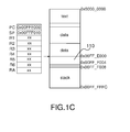
Figures 1A, 1B and1C wherein a physical memory is represented, said memory being used as a buffer containing twodistinct areas - In this example, the
stack 101 grows from address 0x00FF_FFFC downwards, and contains the stacking of multiple frames, a frame comprising local variables, arguments and a return address. Namely, the stack depth is equal to the depth of the functions call tree. - The program is itself in a .
text segment 100, from address 0x0000_0000 upwards. - If the attacker is able to write some data in the buffer which is intended to be used by the program, then some
data 103 can be written into thestack 101. In particular, the return address of a called function can be overwritten and replaced by adifferent address 102 chosen by the attacker (seefigure 1A ). - When the current function returns which also means that the current frame is quitted, then the processor pops the crafted return function (
figure 1 B) and branches on it (seefigure 1 C) . Then, the program is executing thepayload 110 of the attacker, and not the original program. - The stack is deliberately a memory area which can be freely read from and written to. Indeed, some processors are able to forbid some accesses to some given memory areas. For instance, when a MMU (Memory Management Unit) is implemented in a processing system, large portions of the RAM memory (Random Access Memory) can be set in read-only mode. This prevents for instance a program from inadvertently or malevolently overwriting constants. The
.text segment 100 can also be set to read-only mode when executing it. - The stack is nevertheless a general purpose memory chunk where any access is possible, for a better convenience of the execution. Therefore, the attacker is able to corrupt the stack by illegally writing out a buffer boundaries.
- Besides, the attacker can write code in the stack and then to jump on it. This strategy would even be more straightforward. However, this attack technique is easy to counteract by using state-of-the-art techniques, such as the NX bit technology. NX bit technology is described in the document entitled "Data Execution Prevention", Hewlett Packard, 2005.
- Therefore, with most of the state-of-the-art processors, the attacker must inject his payload by writing only data and not machine code. As depicted before, an interesting approach for the attacker is to overwrite the return address memorized in the stack (
Figures 1A-1C ). In that case and as already explained, the program is re-routed elsewhere which means that the control flow is diverted. - Even if the execution of arbitrary code stays complex, several existing techniques allow taking advantage of this situation. For instance, return-oriented programming technique (ROP) makes possible to build a program by borrowing chunks of code from different places, especially in the legacy libraries that are linked with the program (e.g., the C library aka libc, where handy and hardly avoidable functions such as malloc are implemented).
- As a summary, these state-of-the-art attacks alter the execution graph by replacing jump addresses with a forged data that will be erroneously interpreted by the processor as addresses.
- Several existing protections can be used depending of the context.
- Virus can be detected and then quarantined or removed by « anti-viruses » programs, that either check statistically their source code (against some portions of the binary that are renowned to be evil) or dynamically analyze their behaviors. However, anti-viruses act too late, since they detect the virus once it is already inserted in the execution system.
- Other techniques allow to proactively catch the exploit when it is triggered, so as to block it « just-in-time » (JIT) that is to say red-handed. For that purpose, two strategies are usually employed.
- The first strategy is called randomization. The ASLR technique (Address Space Layout Randomization) is one of them. The memory locations of program functions and data are chosen differently at each execution, and thus their addresses are not predictable. However, due to some limitations (e.g. finite length of the addresses), the ASLR can be bypassed. Also, some advanced attacks manage to execute the virus within the ASLR. Hence, this protection can be considered as weak.
- A second strategy is hardening and CFI (Control Flow Integrity) is one example. CFI can be used with a static pre-processing, or dynamically (what we called « JIT »). But this solution is pure software and has therefore several shortcomings. It considerably slows down the execution of the program. Furthermore, it is itself attackable as it is a software only solution. For example, it can be bypassed if there is an exploitable bug in it.
- It would be desirable to address the above issues, to develop a solution for controlling the execution of a code by a processing system.
- According to the invention, there is provided a computer implemented method for controlling dynamically the execution of a code by a processing system, said execution being described by a control flow graph comprising a plurality of basic blocks composed of at least an input node and an output node, a transition in the control flow graph corresponding to a link between an output node of origin belonging to a first basic block and an input node of a second basic block, a plurality of initialization vectors being associated to the output nodes at the time of generating the code, an a priori control word being associated to each input node which is linked to the same output node of origin according the control flow graph, said a priori control word being precomputed at the time of generating the code by applying a predefined deterministic function F to the initialization vector associated to its output node of origin, the following steps being applied once the execution of the output node belonging to a first basic block is terminated and at the time of executing the input node of a second basic block:
- providing the a priori control word associated to the input node of the second basic block;
- providing the initialization vector associated to the output node of the first basic block;
- determining an a posteriori control word by applying to the provided initialization vector the same function F which has been used for generating the a priori control word;
- determining if the a priori control word matches with the a posteriori control word, a forbidden transition in respect to the control flow graph being otherwise detected.
- According to one aspect of the invention, the code execution is interrupted when an output control word and an input control word belonging to two subsequent basic blocs are not identical.
- For example, the second basic block is enciphered at the time of generating the code by using its associated a priori control word as a ciphering key, said method comprising the step of deciphering the second basic block by using its associated a posteriori control word as a deciphering key at the time of executing the input node of said second basic block.
- According to the invention, there is also provided a processing system for executing a code comprising a processor, said system comprising also:
- a memory area configured to store the code to be executed, said code being associated to a control flow graph comprising a plurality of basic blocks composed of at least an input node and an output node, a transition in the control flow graph corresponding to a link between an output node of origin belonging to a first basic block and an input node of a second basic block, said memory area being also configured to store a plurality of initialization vectors associated to the output nodes at the time of generating the code, to store a plurality of a priori control words, an a priori control word being associated to each input node which is linked to the same output node of origin according the control flow graph, said a priori control word being precomputed at the time of generating the code by applying a predefined deterministic function F to the initialization vector associated to its output node of origin;
- an hardware implemented module configured to generate a posteriori control words, an a posteriori control word being generated for a given input node by applying to the initialization vector the same function F which has been used for generating the a priori control associated to the same input node;
- a module configured for determining if an a posteriori control and an a priori control word which are associated to the same input node are matching, a forbidden transition in respect to the control flow graph being otherwise detected.
- As an example, the initialization vectors encode the nature of the jumps implementing allowed transitions in the control flow graph.
- According to one aspect of the invention, the initialization vectors are memorized in the processing system using a set of dedicated registers.
- According to another aspect of the invention, function F can be adapted to take into account an additional input which plays the role of an activation key.
- As an example, the activation key is unique per device.
- Alternatively, the activation key can be unique per program.
- In one embodiment, the basic blocks are enciphered at the time of generating the code by using their associated a priori control words as a ciphering key, said system comprising a module to decipher said basic blocks at the time of executing their input node by using their associated a posteriori control word as a deciphering key.
- According to the invention, there is also provided a computer implemented method for generating an improved version of an initial code intended to be executed on the processing system as described before, comprising the steps of :
- determining a control flow graph representative of an unaltered execution of the code, said control flow graph comprising a plurality of basic blocks composed of at least an input node and an output node, a transition in the control flow graph corresponding to a link between an output node of origin belonging to a first basic block and an input node of a second basic block in the control flow graph;
- generating a plurality of initialization vectors, an initialization vector being associated to each output node at the time of generating the code;
- for each input node, determining an a priori control word associated to each input node which is linked to the same output node of origin according the control flow graph, said a priori control word being precomputed at the time of generating the code by applying a predefined deterministic function F to the initialization vector associated to its output node of origin;
- modifying the initial code by inserting the a priori control words in line with their corresponding instructions.
- The control flow diagram is determined for example through a static analysis of an initial code, said initial code being a source code.
- For example, the control flow diagram is determined through a static analysis of an initial code, said initial code being an assembly code.
- For example, the control flow diagram is determined through a static analysis of an initial code, said initial code being a binary code.
- For example, the initialization vectors are attributed randomly.
- For example, the value of an a priori control word is chosen as a function F of at least a destination address which is the address where the instruction corresponding to an input node following an output node of origin according to the control flow graph is located.
- For example, the a priori control words are inserted inside the code to be executed.
- For example, the a priori control words are inserted in line with the instructions corresponding to their associated input node.
- For example, the initialization vectors are inserted in line with the instructions corresponding to their associated output nodes.
- According to the invention, there is also provided a computer program product, stored on a computer readable medium comprising code means for causing a computer to implement the method for generating an improved version of an initial code as described before.
- A better understanding of the embodiments of the present invention can be obtained from the following detailed description in conjunction with the following drawings, in which:
-
figures 1A, 1B and1C give an example of stack smashing thanks to a buffer overflow; -
figure 2A is an example of control flow diagram; -
figure 2B provides an example of a control flow diagram which is abstracted as an oriented graph containing only basic blocks; -
figure 3 illustrates a method for controlling dynamically the execution of a code; -
figure 4 gives an example of a representation of a control flow graph including transformed input and output nodes; -
figure 5 illustrates an example of a processing system comprising a mechanism to control the execution of a code; -
figure 6 provides an example of a method for generating an improved version of a code which is executable by the processing system according to the invention; -
figure 7 shows the operation of an opcode designed to set a new initialization vector in the form of a finite state machine; -
figure 8 illustrates the upgraded operation of the processing system in the form of a new finite state machine; -
figure 9A provides an example of a simple control flow graph where two nodes are connected with an edge; -
figure 9B gives an example of insertion of the initialization vector at the output node and the a priori control word and its check instruction at the other end of the edge, that is to say the input node. - In the following description, a basic block designates linear portions of code, that is to say a sequence of instructions without deviations from a straight execution.
- Additionally, divergences or convergences are designating locations in the code which are corresponding respectively to the beginning and the end of a basic block. A basic block is composed of at least an input node and an output node which are representing respectively a convergence and a divergence in the control flow graph.
- Moreover, the jump from the output node of a first basic block towards the input node of a second basic block is designated as a transition.
- Further, the word instruction refers to an assembly line of code.
- A source code can be analyzed in order to produce an oriented graph, customarily referred as the CFG (Control Flow Graph). The CFG is an oriented graph wherein each instruction is a node (or vertex) and possible sequences of instructions are indicated by the presence of an oriented edge from one node to the other.
- Basic blocks correspond to linear portions of a control flow graph. In such a block, and without special instruction, the program implicitly continues to the next instruction. This means the register in the processor, which is often referred as the Program Counter (PC), is by default incremented by the size of an instruction after every instruction which is non special (i.e. non-jump).
- The end of a basic block corresponds to an instruction implementing a divergence, for example:
- a conditional jump, like in if, switch, while and goto constructs, "∥" and "&&" binary operators, "?:" ternary operator, and also calls in function arrays;
- a function call / a function return.
- The difference between these two is that a function call / return it implies, in addition to the « sequence break », the saving of some variables on the stack (referred to as a push) for a function call, and the restoration of variables on the stack (referred to as a pop). In assembly language, they also belong to kinds of opcodes: « JUMPs » and « CALLs / « RETs ». For the sake of simplicity, we refer to both sequence breaks as « jumps ».
- In the scope of this invention, it is important to make a difference between statically determined jump destinations and destinations which are discovered dynamically. Several examples are provided below:
- static jumps are gotos to fixed labels or function calls,
- dynamic jumps are all the others.
- There is a characteristic which allows differentiating dynamic jumps into two families.
- A first family comprises the dynamic jumps whose possible destinations are known to belong to a finite state when the program is analyzed. Those are called direct jumps. Direct jumps are:
- if, switch (at least with few cases), while, ∥, &&, call of functions via an array of functions pointers;
- goto to built labels (because they are necessarily within the scope of one function).
- A second family comprises the other dynamic jumps which are called indirect jumps. For these jumps, the number of destinations is unknown at the compilation. Indirect jumps are:
- switch (with many cases, usually > 3) ;
- return from functions that are exported, or
- function calls via a register (virtual functions in C++ for example).
- In this description, the destination of a jump is called a label and is noted L. The destination of a function call is called as the function address and is noted &f, f being the function. It can also be noted f like in the C language. The destination of a return has no special name, but it is implicitly saved by the processor. It is a destination address.
- The entrance of a basic block does not correspond to a particular assembly location. But, when compiling a program, those are known:
- for conditional jumps, as the next instruction that follows the jump instruction;
- for function calls, as the beginning of the function, and for function returns, as the instruction that directly follows the call.
- A special case is for longjumps in C and exceptions in C++ ; in this case, the stack management is « exceptional », as the execution flow.
- A program can be associated with a control flow graph which describes all of its instructions.
-
Figure 2A is an example of control flow graph CFG. Each circle 200-211 stands for one instruction, that is to say one line in the assembly dump of the code. More precisely, the CFG is depicted by the full arrows 212-222. The dashedarrows instruction -
Figure 2B provides an example of a control flow graph which is abstracted as an oriented graph containing only basic blocks 230-235. As already mentioned, a basic block is made of one or more instructions jumping from one to the following without divergences or convergences, except for the first and the last ones. Infigure 2B , the array of function pointers f_ptr contains the addresses of two functions, namely f and g. This representation illustrates function calls / returns but is also applicable to jumps. - Some programs are more complex since they are not monolithic, but use dynamic libraries as for example .so object files under GNU/Linux and .dll under Windows. In this case, the call between basic blocks from the main program to a dynamic library needs to pass through dedicated functions, but that can still be seen as basic blocks.
- The construction of a control flow diagram can be achieved through a static analysis of the source code. It is also possible to recover the structure of a binary code. The recovery might be partial, all the more so as obfuscation techniques are employed to obscure the binary. But still, tools like IDA Pro perform quite well in this functionality and one can write its own disassembly tool.
-
Figure 3 illustrates a method for controlling dynamically the execution of a code andfigure 4 gives an example of a representation of a control flow graph including input and output nodes across which the control is enforced. - This method is computer-implemented. This means that the steps (or substantially all the steps) of the method are executed by at least one processor.
- The method comprises a sequence of several steps which are applied during the code execution each time a basic block execution terminates, that is to say before the execution of a subsequent instruction.
- The unaltered execution of the code can be described by a control flow graph comprising a plurality of basic blocks 420-425 and edges defining allowed transitions between basic blocks. A basic block 420-425 is composed of at least an input node 400-405 and an output node 410-415 which are representing respectively a convergence and a divergence in the control flow graph. As already explained, a node corresponds to an instruction of the code to be executed such as a machine code. According to the invention, a plurality of initialization vectors is attributed to the output nodes at the time of generating the code, for example at the time of compiling a source code or at the time of analyzing an assembly code. In one embodiment, a distinct initialization vector is generated for each output node identified in the control flow graph.
- The initialization vectors can be memorized into the processing system. In a preferred embodiment, the initialization vectors are memorized in the processing system using a set of dedicated registers.
- The method according to the invention carries out several steps once the execution of an output node belonging to a first basic block is terminated and at the time of executing the input node of a second basic block.
- A
step 300 aims at providing an a priori control word associated to the input node of the second basic block. This a priori control word is precomputed at the time of generating the code by applying a predefined function F to an initialization vector, said initialization vector being associated to the output node of origin. Said differently, an allowed transition according to the control flow graph can be defined by an output node of origin which belongs to a first basic block and an input node of destination which belongs to a second basic block. Thus, an initialization vector is associated to the output node of origin and an a priori control word is associated to the input node of destination. More precisely, the a priori control word is deduced of the initialization vector associated to the output node of origin by applying function F to it. - In one embodiment, the a priori control word is inserted inside the code to be executed, for example in line with the instruction corresponding to the input node of the basic blocks.
- Another
step 301 aims at providing the initialization vector associated to the output node of the first basic block. As an example, this initialization vector is memorized in a dedicated register, providing this vector means reading its value for a future use. - In one embodiment, the initialization vector is inserted inside the code to be executed, for example in line with the instruction corresponding to the output node of the basic blocks.
- In one embodiment, a different initialization vector is randomly attributed to output nodes for every authorized transitions or edges in the control flow graph.
- In another
step 302, an a posteriori control word is determined by applying the predefined function F to the provided initialization vector. According to an essential aspect of the invention, the same deterministic function F should be used for computing the a priori and the a posteriori control words associated to a given transition in the control flow graph. - An example of a deterministic function F taking an initialization vector is a SHA (Secured Hash Algorithm) cryptographic hash function of said initialization vector.
- The method also comprises a step of determining 303, 304 if one of the a priori control words matches with the a posteriori control word.
- If the a priori and the a posteriori control words do not match i.e. are different, an
alteration 305 of the code execution is detected. More precisely, this means that a forbidden transition in respect to the control flow graph being is detected. In that case, the code execution may be interrupted. - In one embodiment, after detecting a forbidden transition in respect to the control flow graph, a security policy is enforced by triggering a hardware and/or software function.
- The method according to the invention enables a hardware-assisted protection of a program from attacks that aim at re-routing the execution flow.
- Advantageously, the protection is efficient in terms of security and performance-wise.
- Additionally, some hardware resources such as key registers can be hidden to the attacker. Further, the verification of the control flow graph integrity cannot be bypassed as it can be encoded in a finite state machine, and the function F itself can be hardware implemented or hidden from access of a purported attacker. Another advantage is that the control can be done in parallel with the code execution which minimizes the impact on the execution speed.
-
Figure 5 illustrates a processing system comprising a mechanism to control the execution of a code. - The processing system comprises a central processing unit (CPU) 500 connected to an
internal communication BUS 501, a random access memory (RAM) 502 also connected to the BUS. The processing system further comprises a massstorage device controller 504 managing accesses to a mass memory device, such as hard drive. Mass memory devices suitable for tangibly embodying computer program instructions and data include all forms of non-volatile memory, including by way of example semiconductor memory devices, such as EPROM, EEPROM, and flash memory devices; magnetic disks such as internal hard disks and removable disks; magneto-optical disks; and CD-ROM disks. Any of the foregoing may be supplemented by, or incorporated in, specially designed ASICs (application-specific integrated circuits). - In one embodiment, the processing system comprises a stack stored inside the
random access memory 501. - As an example, a memory area located for example in the
random access memory 502 stores the code to be executed. Alternatively, a memory which is located in themass memory device 504 can be used to store the code to be executed. - This code execution can be described by a control flow graph which comprises a plurality of basic blocks. As already mentioned, a basic block is composed of at least an input node and an output node which are representing respectively a convergence and a divergence in the control flow graph. A plurality of initialization vectors is attributed to the output nodes at the time of generating said code which means before its execution by the processing system.
- The processing system also comprises a memory area wherein said initialization vectors are stored. This memory area can be a memory area which belongs to the stack of the system. Alternatively, this memory area can be implemented by adding a set of dedicated registers to the
CPU 500. - The processing system also comprises a memory area wherein a plurality of a priori control words is stored. As already explained, a priori control words are precomputed at the time of generating the code. For that purpose, a predefined function F is applied to the aforementioned initialization vectors.
- In one embodiment, the a priori control word is inserted inside the code to be executed, for example in line with the instruction corresponding to the input node.
- Further, the processing system comprises a hardware implemented
module 503 for generating a posteriori control words. An a posteriori control word is generated by applying the function F to the initialization vector which is associated to a given output node at the time of executing an instruction which follows the execution of this output node. - Additionally, the processing system comprises a module for determining if an a posteriori control word which has been calculated at the time of leaving a basic block matches an a priori control word. An alteration of the code execution is detected if the two control words do not match. This module can be either software or hardware implemented. For example, this module can be implemented by the
processor 500. -
Figure 6 provides an example of a method for generating an improved version of a code which is executable by the processing system according to the invention. - The improved code can be generated thanks to a computer implemented method which uses an initial code as an input.
- A
step 600 determines a control flow graph representative of an unaltered execution of the initial code. As already explained, the control flow graph comprises a plurality of basic blocks, a basic block being composed of at least an input node and an output node which are representing respectively a convergence and a divergence in the control flow graph. - The method also comprises a
step 601 for generating a plurality of initialization vectors, a given initialization vector being allocated to a given output node. - Further, for each input node linked in the control flow graph to an output node associated to an initialization vector, a
step 602 determines an a priori control word by applying a predefined function F to said initialization vector. - In one embodiment, for example if the code generation platform is similar to the code execution platform depicted in
figure 5 , the function F is hardware accelerated. - Then, the initial code is modified 603 in order to generate an improved version of the code by inserting the a priori control words in line with their corresponding instructions, that is to say the instructions corresponding to their associated input nodes.
- In one embodiment, the
modification 603 of the code also embeds initialization vectors in the improved version of the code in line with their corresponding instructions, that is to say the instructions corresponding to their associated output nodes. - In this description, a program is said to execute with an unaltered control flow diagram if it dynamically upon execution travels through the edges and nodes previously identified statically during the link and/or dynamic link processes, for example at compilation. A processing system such as a processor can typically identify at runtime divergences (that correspond for example to « jump » instructions) but has no means to identify which instruction is a licit destination. This comes from the fact that this information is not present statically in a binary code because the notion of convergence has been semantically removed after compilation.
- This information is nonetheless present while compiling, and can be extracted albeit with non-trivial efforts from a dynamic analysis of the binary. The method according to the invention verifies at runtime that the CFG is unaltered.
- According to the invention, binary information called control word can be added directly to a set of chosen instructions or between instructions in order to secure the association between intended departures and arrival points. This means that the .
text segment 100 will slightly grow. Alternatively, the control words may be calculated on the fly. - The verification of unaltered execution ensures that no new edge is created in the control flow graph, and therefore that an attacker cannot inject new nodes. But, of course, such verification cannot check that the correct (licite) selection of vertices is made. For example, in an "if then else" statement, a program executes with an unaltered control flow graph if after the test, the program counter points either to the beginning of the "then" or of the "else" statement, and not anywhere else.
- In order to keep the control flow graph execution unaltered and to prevent a drastic slow-down in the execution, a combination of new hardware and new information in the software code is implemented. Some values can be added in the binary and these values are called control words in this description. A control word is a precomputed value which is inserted statically in the binary at compile time.
- Besides, the hardware is augmented to check the control words dynamically by recomputing them. This recomputation can be made mandatory, which avoids "forgetting" the verification of "warranty of legality" of one jump in the program.
- The control flow graph alteration is detected unambiguously if the control words do not match across a jump, for example if they differ.
- Different ways of computing control words are provided hereafter by means of examples. They are obtained by the evaluation of a function F, that can have one or more inputs, depending on the targeted security level.
- A minima, it can be checked that the nature of the jump is respected, for example that it is illegal to jump at the beginning of a function from a conditional test such as an if statement. Reciprocally, it is not allowed to jump at the beginning of a basic block from a function call or return. Technically speaking, this means that the nature of the jump can be taken as an input of F while computing a control word.
- However, more advanced verifications can be done. For instance, in case of a jump destination instruction wherein all the possible sources are identified, the source point can be constrained to be within the list of possible origins leading to a given destination instruction. Note that in this description, a jump destination refers to the first instruction of a basic block. Additionally, the jump destination instructions that are considered in this case include conditional jumps and even dynamic jumps, except as discussed before instructions such as return from exported function or calls to virtual functions.
- This implies a notion of classes of compatible source and destination pairs, that can be enforced by initialization vectors that creates classes of matching divergences and convergences. Concretely, this means that the initialization vector is an input to the function F in charge of creating control words. The previous minimal example (the nature of jump shall impact the control word) can be seen as a special case of an initialization vector wherein the nature of the jump is implicitly converted as an initialization vector. For example:
- in case of an if instruction, the initialization vector will be equal to 0x00;
- in case of a call instruction, the initialization vector will be equal to 0x01;
- and so on for other kind of jumps which may be encountered in the code.
- According to one aspect of the invention, the value of a control word can be chosen as a function of the destination address that should be reached after a jump instruction. The advantage is that reuse and displacement of control words are impossible.
- In another embodiment, the control words may depend on a key concealed in the processor. The advantage of this embodiment is that it prevents the dynamic forgery of the control words.
- In another embodiment, the control words may depend on a key concealed in a segment of the code that is not readable from outside. The advantage of this embodiment is also that it prevents the dynamic forgery of the control words.
- A combination of these embodiments may also be considered, which means that the F function may have two or three inputs in addition to the mandatory initialization vector.
- In a processing system implementing the invention, the binary .
text section 100 must be upgraded in order to embed the control words and/or the initialization vectors. They can be placed after the opcodes in line. This means that the words must be longer or that a second memory must be used as a « padding » of the first one. Alternatively, specific instructions may be used, said instructions being adapted such that: - initialization vectors are loaded before any "jump" operation;
- a control word check computed knowing the current initialization vector is requested, along with the expected (a priori) control word value.
- According to the invention, the initial vectors can be computed and allocated using different techniques. For instance, every parent vertex (also called output nodes) corresponding to any licit input node has identical initialization vectors attributed, so that an initialization vector depends only on the destination. This allows a graph traversal with « coloring » of vertices.
- In an alternative embodiment, the parent node can dynamically compute the initialization vector or select the initialization vector in a precomputed table depending on the computed or selected destination. This implementation has the advantage of increasing the number of possible initialization vectors and thus decreasing the possibility of undetected malicious control flow hijacking.
- In addition to classical registers that contain the current opcode and the current address and usually called PC (Program Counter), at least one register is added to the system. This additional register comprises the initialization vector.
- In one embodiment, this initial vector can be set and reset by a specific instructions which is added to the instruction set of the processing system. We recall that the initialization vector is a piece of information that is required for the a priori and a posteriori control words (over a « jump ») to be compatible by association.
- A deterministic function F is used and designed to compute the control words. This function F is implemented in the processing system. F takes as input at least the initialization vector, which for instance encodes the nature of the opcode, that is to say: jump or not, and if jump, several subcategories can be defined (classes of matching end points).
- As previously stated, an example of a deterministic function of an initialization vector is a SHA cryptographic hash of said initialization vector.
- The function F also aims at recomputing dynamically and just in time (JIT) a control word during the program execution. It is in particular automatically reevaluated if the current instruction is a jump (this can be achieved trivially in the pipeline of a processor, and is indeed most of the time already implemented, let alone to know whether the PC must be incremented [no jump] or loaded from an external value [jump]).
- The result of applying the F function is a control word, that is compared with a Boolean test to the statically and read-only declared a priori control word, which can be found in the binary.
- The function F can advantageously be adapted to take into account an additional input which plays the role of a key. As already mentioned, this key can be unique per device or unique per program. Alternatively, it can be unique per process, a process being an instance of a program. Using a key has the advantage to associate one binary code to one device or program or process, thereby further reducing the possibility of an attacker to fraud the protection. In that case, a second additional register is required to host the key.
- So, in general, for flexibility considerations, the function F might well depends on only a subset of these arguments, depending on the expected level of verification. For example, if the association between the code and the processing system is not a requirement, the « key » input can be ignored.
- The F function can be chosen as a compression function. Indeed, since the output must fit on a limited amount of bits which will generally correspond to the word size used by the system (for example 32 bits) minus the possible opcode length when the control word is introduced by an instruction in the code. This value must be large enough to avoid accidental control words equality, which happens with probability about 2-#bits, where #bits is the control word bitwidth.
- The F function can be advantageously chosen so that it will be collision resistant.
- Additionally, the F function can be one-way (at least for the key). That way, it will not possible to recover its arguments by knowing its output. This will advantageously protect the processing system against the recovery of the key.
- Then the F function can be chosen such that it will be fast to compute, ideally in one clock cycle or with the number of clock cycles required to execute one instruction on the processing system, so as not to impede the latency.
- It is also possible to add optional new opcodes. An opcode can be added to initialize/set a new initialization vector, which can be for example equal to zero by default.
-
Figure 7 shows the operation of an opcode designed to set a new initialization vector in the form of a finite state machine with onestate 700 and three transitions 701-703. - An opcode can be added to request the verification of a control word, in the case this is not done by default at each clock cycle. This implicit behavior does not slow down the execution, because the control word computation and check is done in parallel with the nominal program execution.
-
Figure 8 illustrates the upgraded operation of the processing system in the form of a new finite state machine with twostates transitions - the current opcode is a jump (in the general sense, i.e. a conditional branch, a function call or return), and
- if it is a conditional branch, the jump is effective (opposed to « continue to the next instruction »).
- In case the a priori and a posteriori control words do not match after a jump, the new finite state machine enters an
error state 803 which means that the control flow graph has been corrupted. In that case, several actions can be taken, for example halt the program execution and/or active some defensive countermeasures (erase some secrets from memory). - In another embodiment, the opcodes can be enciphered by a transformation function that depends on the control words. This does not impede the normal execution of the code, as the verification of the control word is necessary before executing the sequel of the code: hence the control word is readily available to decipher in real-time the arriving enciphered opcodes.
- The advantage of this technique is that code injection or reuse elsewhere is rendered very chancy, if not impossible. Furthermore, if for some reason the code happens to leak out of the processing system, then it will be unintelligible, and thus impossible to reverse-engineer, for instance so as to find vulnerabilities in it.
- In one embodiment, encoding the opcodes is done using a block cipher, the key being equal or derived from the control word, for example by using a hash function.
- In one embodiment the block cipher is used in conjunction with cryptographic mode of operations such as ECB (Electronic Code Book), CBC (Cipher Block Chaining), PCBC (Propagating Cipher Block Chaining), CFB (Cipher Feedback), OFB (Output Feedback) and CTR (CounTeR).
- In one embodiment, encoding the opcodes is done by means of a stream cipher, the key being equal or derived from the control word, for example by using a hash function.
-
Figures 9A provides an example of a simple control flow graph where two nodes are connected with avertice 910.Figure 9B gives an example of insertion of the a priori control word and its check at the other end of thevertice 910. - In order to forbid an attacker from derouting a program by overwriting the return addresses, the control flow graph is made more robust by modifying the ends of the basic blocks, so that:
- on leaving a basic block, some value based on the possible destinations is computed. It is called a set of a priori control words;
- on entering a basic block, the precomputed control word fitting this location is checked against the control word from the incoming vertex. By design, those two values differ only if a new edge, either to an existing node or to a newly created (forged) node, has been created in the control flow graph.
- The transmission of the control word can be done on the stack. The modified final instruction of the
basic block 900 and the modified first instruction of thebasic bloc 901 are both represented hatched subset of instructions. - For functions, a similar mechanism can be used, with in addition the push / pop of the a priori control words. This is depicted in listing 2 which shows on an example wherein transitions are verified along function calls / returns in a control flow graph.
Listing 2 Without protection With protection ret pop IV (deciphered) ret (equivalent to: • pop %eax • jmp %eax+4 ) call f push IV (enciphered) call f (equivalent to: • push return_address • jmp f ) - In one embodiment the initialization vector (IV) is not pushed in the clear on the stack. Instead, it is encrypted by some function that depend on an exposed key (to avoid their retrieval) and on their address (namely %esp, to avoid replay).
- In mirror, the state machine of the hardware must be upgraded, for the verification to be done automatically. This will prevent jumping at an unplausible address, that is to say inside a basic block.
- The processing system, methods and configurations as described above and in the drawings are for ease of description only and are not meant to restrict the apparatus or methods to a particular arrangement or process in use.
Claims (20)
- A computer implemented method for controlling dynamically the execution of a code by a processing system, said execution being described by a control flow graph comprising a plurality of basic blocks composed of at least an input node and an output node, a transition in the control flow graph corresponding to a link between an output node of origin belonging to a first basic block and an input node of a second basic block, a plurality of initialization vectors being associated to the output nodes at the time of generating the code, an a priori control word being associated to each input node which is linked to the same output node of origin according the control flow graph, said a priori control word being precomputed at the time of generating the code by applying a predefined deterministic function F to the initialization vector associated to its output node of origin, the following steps being applied once the execution of the output node belonging to a first basic block is terminated and at the time of executing the input node of a second basic block:- providing (300) the a priori control word associated to the input node of the second basic block;- providing (301) the initialization vector associated to the output node of the first basic block;- determining (302) an a posteriori control word by applying to the provided initialization vector the same function F which has been used for generating the a priori control word;- determining (303, 304) if the a priori control word matches with the a posteriori control word, a forbidden transition in respect to the control flow graph being otherwise detected (305).
- A method according to claim 1 wherein the code execution is interrupted when an output control word and an input control word belonging to two subsequent basic blocs are not identical.
- A method according to one of the preceding claims wherein the second basic block is enciphered at the time of generating the code by using its associated a priori control word as a ciphering key, said method comprising the step of deciphering the second basic block by using its associated a posteriori control word as a deciphering key at the time of executing the input node of said second basic block.
- A processing system for executing a code comprising a processor (500), said system comprising also:- a memory area (501) configured to store the code to be executed, said code being associated to a control flow graph comprising a plurality of basic blocks composed of at least an input node and an output node, a transition in the control flow graph corresponding to a link between an output node of origin belonging to a first basic block and an input node of a second basic block, said memory area being also configured to store a plurality of initialization vectors associated to the output nodes at the time of generating the code, to store a plurality of a priori control words, an a priori control word being associated to each input node which is linked to the same output node of origin according the control flow graph, said a priori control word being precomputed at the time of generating the code by applying a predefined deterministic function F to the initialization vector associated to its output node of origin;- an hardware implemented module (503) configured to generate a posteriori control words, an a posteriori control word being generated for a given input node by applying to the initialization vector the same function F which has been used for generating the a priori control associated to the same input node;- a module configured for determining if an a posteriori control and an a priori control word which are associated to the same input node are matching, a forbidden transition in respect to the control flow graph being otherwise detected.
- A processing system according to claim 4 wherein the initialization vectors encode the nature of the jumps implementing allowed transitions in the control flow graph.
- A processing system according to one of the claims 4 or 5 wherein the initialization vectors are memorized in the processing system using a set of dedicated registers.
- A processing system according to one of the claims 4 to 6 wherein function F is adapted to take into account an additional input which plays the role of an activation key.
- A processing system according to one of the claims 4 to 7 wherein the activation key is unique per device.
- A processing system according to one of the claims 4 to 7 wherein the activation key is unique per program.
- A processing system to one of the claims 4 to 9 wherein the basic blocks are enciphered at the time of generating the code by using their associated a priori control words as a ciphering key, said system comprising a module to decipher said basic blocks at the time of executing their input node by using their associated a posteriori control word as a deciphering key.
- A computer implemented method for generating an improved version of an initial code intended to be executed on the processing system according to one of the claims 3 to 10, comprising the steps of :- determining (600) a control flow graph representative of an unaltered execution of the code, said control flow graph comprising a plurality of basic blocks composed of at least an input node and an output node, a transition in the control flow graph corresponding to a link between an output node of origin belonging to a first basic block and an input node of a second basic block in the control flow graph;- generating (601) a plurality of initialization vectors, an initialization vector being associated to each output node at the time of generating the code;- for each input node, determining (602) an a priori control word associated to each input node which is linked to the same output node of origin according the control flow graph, said a priori control word being precomputed at the time of generating the code by applying a predefined deterministic function F to the initialization vector associated to its output node of origin;- modifying (603) the initial code by inserting the a priori control words in line with their corresponding instructions.
- A method according to claim 11 wherein the control flow diagram is determined through a static analysis of an initial code, said initial code being a source code.
- A method according to claim 11 wherein the control flow diagram is determined through a static analysis of an initial code, said initial code being an assembly code.
- A method according to claim 11 wherein the control flow diagram is determined through a static analysis of an initial code, said initial code being a binary code
- A method according to one of the claims 11 to 14 wherein the initialization vectors are attributed randomly.
- A method according to one of the claims 11 to 14 wherein the value of an a priori control word is chosen as a function F of at least a destination address which is the address where the instruction corresponding to an input node following an output node of origin according to the control flow graph is located.
- A method according to one of the claims 11 to 16 wherein the a priori control words are inserted inside the code to be executed.
- A method according to claim 17 wherein the a priori control words are inserted in line with the instructions corresponding to their associated input node.
- A method according to one of the claims 11 to 17 wherein the initialization vectors are inserted in line with the instructions corresponding to their associated output nodes.
- A computer program product, stored on a computer readable medium comprising code means for causing a computer to implement the method according to of the claims 1 to 3.
Priority Applications (5)
| Application Number | Priority Date | Filing Date | Title |
|---|---|---|---|
| EP14305954.1A EP2958044B1 (en) | 2014-06-20 | 2014-06-20 | A computer implemented method and a system for controlling dynamically the execution of a code |
| CN201580033156.2A CN107077562B (en) | 2014-06-20 | 2015-06-19 | Computer-implemented method and system for dynamically controlling code execution |
| US15/317,325 US10354064B2 (en) | 2014-06-20 | 2015-06-19 | Computer implemented method and a system for controlling dynamically the execution of a code |
| PCT/EP2015/063880 WO2015193500A1 (en) | 2014-06-20 | 2015-06-19 | A computer implemented method and a system for controlling dynamically the execution of a code |
| HK16106050.6A HK1218172A1 (en) | 2014-06-20 | 2016-05-27 | A computer implemented method and a system for controlling dynamically the execution of a code |
Applications Claiming Priority (1)
| Application Number | Priority Date | Filing Date | Title |
|---|---|---|---|
| EP14305954.1A EP2958044B1 (en) | 2014-06-20 | 2014-06-20 | A computer implemented method and a system for controlling dynamically the execution of a code |
Publications (2)
| Publication Number | Publication Date |
|---|---|
| EP2958044A1 true EP2958044A1 (en) | 2015-12-23 |
| EP2958044B1 EP2958044B1 (en) | 2019-09-18 |
Family
ID=51485531
Family Applications (1)
| Application Number | Title | Priority Date | Filing Date |
|---|---|---|---|
| EP14305954.1A Active EP2958044B1 (en) | 2014-06-20 | 2014-06-20 | A computer implemented method and a system for controlling dynamically the execution of a code |
Country Status (5)
| Country | Link |
|---|---|
| US (1) | US10354064B2 (en) |
| EP (1) | EP2958044B1 (en) |
| CN (1) | CN107077562B (en) |
| HK (1) | HK1218172A1 (en) |
| WO (1) | WO2015193500A1 (en) |
Cited By (1)
| Publication number | Priority date | Publication date | Assignee | Title |
|---|---|---|---|---|
| US11442738B2 (en) | 2017-09-22 | 2022-09-13 | Commissariat A L'energie Atomique Et Aux Energies Alternatives | Method for executing a machine code of a secure function |
Families Citing this family (14)
| Publication number | Priority date | Publication date | Assignee | Title |
|---|---|---|---|---|
| US10365937B2 (en) * | 2015-07-24 | 2019-07-30 | Red Hat Israel, Ltd. | Entropy increase by executable loader |
| US10007787B2 (en) * | 2015-12-28 | 2018-06-26 | International Business Machines Corporation | Runtime return-oriented programming detection |
| US10268601B2 (en) | 2016-06-17 | 2019-04-23 | Massachusetts Institute Of Technology | Timely randomized memory protection |
| US10310991B2 (en) * | 2016-08-11 | 2019-06-04 | Massachusetts Institute Of Technology | Timely address space randomization |
| CN106407809B (en) * | 2016-09-20 | 2019-03-01 | 四川大学 | A kind of Linux platform malware detection method |
| US10768979B2 (en) * | 2016-09-23 | 2020-09-08 | Apple Inc. | Peer-to-peer distributed computing system for heterogeneous device types |
| US20180203885A1 (en) * | 2017-01-18 | 2018-07-19 | Microsoft Technology Licensing, Llc | Controlling creation/access of physically senses features |
| CN107545174B (en) * | 2017-08-22 | 2020-03-10 | 武汉大学 | System and method for resisting control flow hijacking based on LLVM |
| US10657025B2 (en) * | 2018-10-18 | 2020-05-19 | Denso International America, Inc. | Systems and methods for dynamically identifying data arguments and instrumenting source code |
| US10628286B1 (en) | 2018-10-18 | 2020-04-21 | Denso International America, Inc. | Systems and methods for dynamically identifying program control flow and instrumenting source code |
| KR102569820B1 (en) * | 2018-10-25 | 2023-08-24 | 에스케이하이닉스 주식회사 | Memory controller and operating method thereof |
| US11809563B2 (en) * | 2021-07-07 | 2023-11-07 | University Of South Florida | System and method for protecting against control-flow attacks |
| CN116501378B (en) * | 2023-06-27 | 2023-09-12 | 武汉大数据产业发展有限公司 | Implementation method and device for reverse engineering reduction source code and electronic equipment |
| CN117270878B (en) * | 2023-11-22 | 2024-02-09 | 常熟理工学院 | Constraint condition extraction method and device for program variables in program execution path |
Family Cites Families (11)
| Publication number | Priority date | Publication date | Assignee | Title |
|---|---|---|---|---|
| US7721275B2 (en) * | 2004-05-14 | 2010-05-18 | Sap Ag | Data-flow based post pass optimization in dynamic compilers |
| US7506217B2 (en) * | 2005-12-30 | 2009-03-17 | Intel Corporation | Apparatus and method for software-based control flow checking for soft error detection to improve microprocessor reliability |
| CN101416197A (en) * | 2006-02-06 | 2009-04-22 | 松下电器产业株式会社 | Program obfuscator |
| US8046751B1 (en) * | 2007-01-11 | 2011-10-25 | The Mathworks, Inc. | Structuring unstructured regions in a control flow graph |
| US8359583B2 (en) * | 2007-08-22 | 2013-01-22 | Coverity, Inc. | Methods for selectively pruning false paths in graphs that use high-precision state information |
| EP2300952B1 (en) * | 2008-05-30 | 2012-07-11 | Nxp B.V. | A method for adapting and executing a computer program and computer program product and computer architecture therefor |
| US8285999B1 (en) * | 2008-12-05 | 2012-10-09 | The Research Foundation Of State University Of New York | System and method for authenticating remote execution |
| US8516467B2 (en) * | 2010-01-29 | 2013-08-20 | Nintendo Co., Ltd. | Method and apparatus for enhancing comprehension of code time complexity and flow |
| US9965744B1 (en) * | 2012-06-29 | 2018-05-08 | Google Llc | Automatic dynamic vetting of browser extensions and web applications |
| US9298453B2 (en) * | 2012-07-03 | 2016-03-29 | Microsoft Technology Licensing, Llc | Source code analytics platform using program analysis and information retrieval |
| US9824214B2 (en) * | 2014-08-15 | 2017-11-21 | Securisea, Inc. | High performance software vulnerabilities detection system and methods |
-
2014
- 2014-06-20 EP EP14305954.1A patent/EP2958044B1/en active Active
-
2015
- 2015-06-19 WO PCT/EP2015/063880 patent/WO2015193500A1/en active Application Filing
- 2015-06-19 US US15/317,325 patent/US10354064B2/en active Active
- 2015-06-19 CN CN201580033156.2A patent/CN107077562B/en active Active
-
2016
- 2016-05-27 HK HK16106050.6A patent/HK1218172A1/en unknown
Non-Patent Citations (4)
| Title |
|---|
| HEWLETT PACKARD, DATA EXECUTION PREVENTION, 2005 |
| MARTÍN ABADI ET AL: "Control-flow integrity principles, implementations, and applications", ACM TRANSACTIONS ON INFORMATION AND SYSTEM SECURITY, ACM, NEW YORK, NY, US, vol. 13, no. 1, 1 October 2009 (2009-10-01), pages 4:1 - 4:40, XP001574403, ISSN: 1094-9224, [retrieved on 20091001], DOI: 10.1145/1609956.1609960 * |
| NAHMSUK OH ET AL: "Control-Flow Checking by Software Signatures", IEEE TRANSACTIONS ON RELIABILITY, IEEE SERVICE CENTER, PISCATAWAY, NJ, US, vol. 51, no. 1, 1 March 2002 (2002-03-01), XP011079413, ISSN: 0018-9529 * |
| NAMJOO M ED - INSTITUTE OF ELECTRICAL AND ELECTRONICS ENGINEERS: "TECHNIQUES FOR CONCURRENT TESTING OF VLSI PROCESSOR OPERATION", QUALITY PRODUCTIVITY PROFIT. PHILADELPHIA, 15 - 18 NOVEMBER 1982; [INTERNATIONAL TEST CONFERENCE], SILVER SPRING, IEEE COMP. SOC. PRESS, US, vol. SYMP. 1982, 1 November 1982 (1982-11-01), pages 461 - 468, XP000746184 * |
Cited By (1)
| Publication number | Priority date | Publication date | Assignee | Title |
|---|---|---|---|---|
| US11442738B2 (en) | 2017-09-22 | 2022-09-13 | Commissariat A L'energie Atomique Et Aux Energies Alternatives | Method for executing a machine code of a secure function |
Also Published As
| Publication number | Publication date |
|---|---|
| US20170124322A1 (en) | 2017-05-04 |
| WO2015193500A1 (en) | 2015-12-23 |
| US10354064B2 (en) | 2019-07-16 |
| EP2958044B1 (en) | 2019-09-18 |
| CN107077562A (en) | 2017-08-18 |
| CN107077562B (en) | 2020-11-06 |
| HK1218172A1 (en) | 2017-02-03 |
Similar Documents
| Publication | Publication Date | Title |
|---|---|---|
| EP2958044B1 (en) | A computer implemented method and a system for controlling dynamically the execution of a code | |
| KR102558104B1 (en) | Call path dependent authentication | |
| US9514305B2 (en) | Code pointer authentication for hardware flow control | |
| US9165138B2 (en) | Mitigation of function pointer overwrite attacks | |
| KR101256149B1 (en) | Method and apparatus for securing indirect function calls by using program counter encoding | |
| US20110191848A1 (en) | Preventing malicious just-in-time spraying attacks | |
| KR101216995B1 (en) | A code encryption and decryption device against reverse engineering based on indexed table and the method thereof | |
| US11232194B2 (en) | Method for executing a binary code of a secure function with a microprocessor | |
| US20200380150A1 (en) | Method of encoding and decoding memory data for software security, recording medium and apparatus for performing the method | |
| KR20160145014A (en) | Hardware-based stack control information protection | |
| JP2013535725A (en) | A method implemented by a processor for ensuring the integrity of software | |
| Qiu et al. | Physical unclonable functions-based linear encryption against code reuse attacks | |
| US8694548B2 (en) | Defense-in-depth security for bytecode executables | |
| US11704128B2 (en) | Method for executing a machine code formed from blocks having instructions to be protected, each instruction associated with a construction instruction to modify a signature of the block | |
| CN111475168A (en) | Code compiling method and device | |
| WO2016198831A1 (en) | Apparatus and methods for transitioning between a secure area and a less-secure area | |
| US20240012886A1 (en) | Code flow protection with error propagation | |
| US11442738B2 (en) | Method for executing a machine code of a secure function | |
| EP3944106A1 (en) | Obfuscating method of protecting code | |
| US20240069917A1 (en) | Method for executing a machine code by means of a computer | |
| Forte | Automatic Binary Analysis and Instrumentation of Embedded Firmware for a Control-Flow Integrity Solution |
Legal Events
| Date | Code | Title | Description |
|---|---|---|---|
| PUAI | Public reference made under article 153(3) epc to a published international application that has entered the european phase |
Free format text: ORIGINAL CODE: 0009012 |
|
| AK | Designated contracting states |
Kind code of ref document: A1 Designated state(s): AL AT BE BG CH CY CZ DE DK EE ES FI FR GB GR HR HU IE IS IT LI LT LU LV MC MK MT NL NO PL PT RO RS SE SI SK SM TR |
|
| AX | Request for extension of the european patent |
Extension state: BA ME |
|
| 17P | Request for examination filed |
Effective date: 20160620 |
|
| RBV | Designated contracting states (corrected) |
Designated state(s): AL AT BE BG CH CY CZ DE DK EE ES FI FR GB GR HR HU IE IS IT LI LT LU LV MC MK MT NL NO PL PT RO RS SE SI SK SM TR |
|
| REG | Reference to a national code |
Ref country code: HK Ref legal event code: DE Ref document number: 1218172 Country of ref document: HK |
|
| RIN1 | Information on inventor provided before grant (corrected) |
Inventor name: GUILLEY, SYLVAIN Inventor name: PORTEBOEUF, THIBAULT |
|
| RIC1 | Information provided on ipc code assigned before grant |
Ipc: G06F 21/54 20130101AFI20190118BHEP |
|
| GRAP | Despatch of communication of intention to grant a patent |
Free format text: ORIGINAL CODE: EPIDOSNIGR1 |
|
| STAA | Information on the status of an ep patent application or granted ep patent |
Free format text: STATUS: GRANT OF PATENT IS INTENDED |
|
| RIN1 | Information on inventor provided before grant (corrected) |
Inventor name: PORTEBOEUF, THIBAULT Inventor name: GUILLEY, SYLVAIN |
|
| INTG | Intention to grant announced |
Effective date: 20190307 |
|
| GRAJ | Information related to disapproval of communication of intention to grant by the applicant or resumption of examination proceedings by the epo deleted |
Free format text: ORIGINAL CODE: EPIDOSDIGR1 |
|
| STAA | Information on the status of an ep patent application or granted ep patent |
Free format text: STATUS: REQUEST FOR EXAMINATION WAS MADE |
|
| REG | Reference to a national code |
Ref country code: DE Ref legal event code: R079 Ref document number: 602014053777 Country of ref document: DE Free format text: PREVIOUS MAIN CLASS: G06F0021540000 Ipc: G06F0008750000 |
|
| GRAR | Information related to intention to grant a patent recorded |
Free format text: ORIGINAL CODE: EPIDOSNIGR71 |
|
| GRAS | Grant fee paid |
Free format text: ORIGINAL CODE: EPIDOSNIGR3 |
|
| STAA | Information on the status of an ep patent application or granted ep patent |
Free format text: STATUS: GRANT OF PATENT IS INTENDED |
|
| INTC | Intention to grant announced (deleted) | ||
| GRAA | (expected) grant |
Free format text: ORIGINAL CODE: 0009210 |
|
| STAA | Information on the status of an ep patent application or granted ep patent |
Free format text: STATUS: THE PATENT HAS BEEN GRANTED |
|
| RIC1 | Information provided on ipc code assigned before grant |
Ipc: G06F 21/54 20130101ALI20190715BHEP Ipc: G06F 8/75 20180101AFI20190715BHEP |
|
| AK | Designated contracting states |
Kind code of ref document: B1 Designated state(s): AL AT BE BG CH CY CZ DE DK EE ES FI FR GB GR HR HU IE IS IT LI LT LU LV MC MK MT NL NO PL PT RO RS SE SI SK SM TR |
|
| INTG | Intention to grant announced |
Effective date: 20190812 |
|
| REG | Reference to a national code |
Ref country code: GB Ref legal event code: FG4D |
|
| REG | Reference to a national code |
Ref country code: CH Ref legal event code: EP |
|
| REG | Reference to a national code |
Ref country code: DE Ref legal event code: R096 Ref document number: 602014053777 Country of ref document: DE |
|
| REG | Reference to a national code |
Ref country code: AT Ref legal event code: REF Ref document number: 1182117 Country of ref document: AT Kind code of ref document: T Effective date: 20191015 |
|
| REG | Reference to a national code |
Ref country code: IE Ref legal event code: FG4D |
|
| REG | Reference to a national code |
Ref country code: NL Ref legal event code: MP Effective date: 20190918 |
|
| PG25 | Lapsed in a contracting state [announced via postgrant information from national office to epo] |
Ref country code: NO Free format text: LAPSE BECAUSE OF FAILURE TO SUBMIT A TRANSLATION OF THE DESCRIPTION OR TO PAY THE FEE WITHIN THE PRESCRIBED TIME-LIMIT Effective date: 20191218 Ref country code: SE Free format text: LAPSE BECAUSE OF FAILURE TO SUBMIT A TRANSLATION OF THE DESCRIPTION OR TO PAY THE FEE WITHIN THE PRESCRIBED TIME-LIMIT Effective date: 20190918 Ref country code: HR Free format text: LAPSE BECAUSE OF FAILURE TO SUBMIT A TRANSLATION OF THE DESCRIPTION OR TO PAY THE FEE WITHIN THE PRESCRIBED TIME-LIMIT Effective date: 20190918 Ref country code: FI Free format text: LAPSE BECAUSE OF FAILURE TO SUBMIT A TRANSLATION OF THE DESCRIPTION OR TO PAY THE FEE WITHIN THE PRESCRIBED TIME-LIMIT Effective date: 20190918 Ref country code: LT Free format text: LAPSE BECAUSE OF FAILURE TO SUBMIT A TRANSLATION OF THE DESCRIPTION OR TO PAY THE FEE WITHIN THE PRESCRIBED TIME-LIMIT Effective date: 20190918 Ref country code: BG Free format text: LAPSE BECAUSE OF FAILURE TO SUBMIT A TRANSLATION OF THE DESCRIPTION OR TO PAY THE FEE WITHIN THE PRESCRIBED TIME-LIMIT Effective date: 20191218 |
|
| REG | Reference to a national code |
Ref country code: LT Ref legal event code: MG4D |
|
| PG25 | Lapsed in a contracting state [announced via postgrant information from national office to epo] |
Ref country code: GR Free format text: LAPSE BECAUSE OF FAILURE TO SUBMIT A TRANSLATION OF THE DESCRIPTION OR TO PAY THE FEE WITHIN THE PRESCRIBED TIME-LIMIT Effective date: 20191219 Ref country code: AL Free format text: LAPSE BECAUSE OF FAILURE TO SUBMIT A TRANSLATION OF THE DESCRIPTION OR TO PAY THE FEE WITHIN THE PRESCRIBED TIME-LIMIT Effective date: 20190918 Ref country code: LV Free format text: LAPSE BECAUSE OF FAILURE TO SUBMIT A TRANSLATION OF THE DESCRIPTION OR TO PAY THE FEE WITHIN THE PRESCRIBED TIME-LIMIT Effective date: 20190918 Ref country code: RS Free format text: LAPSE BECAUSE OF FAILURE TO SUBMIT A TRANSLATION OF THE DESCRIPTION OR TO PAY THE FEE WITHIN THE PRESCRIBED TIME-LIMIT Effective date: 20190918 |
|
| REG | Reference to a national code |
Ref country code: AT Ref legal event code: MK05 Ref document number: 1182117 Country of ref document: AT Kind code of ref document: T Effective date: 20190918 |
|
| PG25 | Lapsed in a contracting state [announced via postgrant information from national office to epo] |
Ref country code: ES Free format text: LAPSE BECAUSE OF FAILURE TO SUBMIT A TRANSLATION OF THE DESCRIPTION OR TO PAY THE FEE WITHIN THE PRESCRIBED TIME-LIMIT Effective date: 20190918 Ref country code: NL Free format text: LAPSE BECAUSE OF FAILURE TO SUBMIT A TRANSLATION OF THE DESCRIPTION OR TO PAY THE FEE WITHIN THE PRESCRIBED TIME-LIMIT Effective date: 20190918 Ref country code: PL Free format text: LAPSE BECAUSE OF FAILURE TO SUBMIT A TRANSLATION OF THE DESCRIPTION OR TO PAY THE FEE WITHIN THE PRESCRIBED TIME-LIMIT Effective date: 20190918 Ref country code: RO Free format text: LAPSE BECAUSE OF FAILURE TO SUBMIT A TRANSLATION OF THE DESCRIPTION OR TO PAY THE FEE WITHIN THE PRESCRIBED TIME-LIMIT Effective date: 20190918 Ref country code: AT Free format text: LAPSE BECAUSE OF FAILURE TO SUBMIT A TRANSLATION OF THE DESCRIPTION OR TO PAY THE FEE WITHIN THE PRESCRIBED TIME-LIMIT Effective date: 20190918 Ref country code: PT Free format text: LAPSE BECAUSE OF FAILURE TO SUBMIT A TRANSLATION OF THE DESCRIPTION OR TO PAY THE FEE WITHIN THE PRESCRIBED TIME-LIMIT Effective date: 20200120 Ref country code: EE Free format text: LAPSE BECAUSE OF FAILURE TO SUBMIT A TRANSLATION OF THE DESCRIPTION OR TO PAY THE FEE WITHIN THE PRESCRIBED TIME-LIMIT Effective date: 20190918 Ref country code: IT Free format text: LAPSE BECAUSE OF FAILURE TO SUBMIT A TRANSLATION OF THE DESCRIPTION OR TO PAY THE FEE WITHIN THE PRESCRIBED TIME-LIMIT Effective date: 20190918 |
|
| PG25 | Lapsed in a contracting state [announced via postgrant information from national office to epo] |
Ref country code: IS Free format text: LAPSE BECAUSE OF FAILURE TO SUBMIT A TRANSLATION OF THE DESCRIPTION OR TO PAY THE FEE WITHIN THE PRESCRIBED TIME-LIMIT Effective date: 20200224 Ref country code: SM Free format text: LAPSE BECAUSE OF FAILURE TO SUBMIT A TRANSLATION OF THE DESCRIPTION OR TO PAY THE FEE WITHIN THE PRESCRIBED TIME-LIMIT Effective date: 20190918 Ref country code: SK Free format text: LAPSE BECAUSE OF FAILURE TO SUBMIT A TRANSLATION OF THE DESCRIPTION OR TO PAY THE FEE WITHIN THE PRESCRIBED TIME-LIMIT Effective date: 20190918 Ref country code: CZ Free format text: LAPSE BECAUSE OF FAILURE TO SUBMIT A TRANSLATION OF THE DESCRIPTION OR TO PAY THE FEE WITHIN THE PRESCRIBED TIME-LIMIT Effective date: 20190918 |
|
| REG | Reference to a national code |
Ref country code: DE Ref legal event code: R097 Ref document number: 602014053777 Country of ref document: DE |
|
| PLBE | No opposition filed within time limit |
Free format text: ORIGINAL CODE: 0009261 |
|
| STAA | Information on the status of an ep patent application or granted ep patent |
Free format text: STATUS: NO OPPOSITION FILED WITHIN TIME LIMIT |
|
| PG2D | Information on lapse in contracting state deleted |
Ref country code: IS |
|
| PG25 | Lapsed in a contracting state [announced via postgrant information from national office to epo] |
Ref country code: DK Free format text: LAPSE BECAUSE OF FAILURE TO SUBMIT A TRANSLATION OF THE DESCRIPTION OR TO PAY THE FEE WITHIN THE PRESCRIBED TIME-LIMIT Effective date: 20190918 Ref country code: IS Free format text: LAPSE BECAUSE OF FAILURE TO SUBMIT A TRANSLATION OF THE DESCRIPTION OR TO PAY THE FEE WITHIN THE PRESCRIBED TIME-LIMIT Effective date: 20200119 |
|
| 26N | No opposition filed |
Effective date: 20200619 |
|
| PG25 | Lapsed in a contracting state [announced via postgrant information from national office to epo] |
Ref country code: SI Free format text: LAPSE BECAUSE OF FAILURE TO SUBMIT A TRANSLATION OF THE DESCRIPTION OR TO PAY THE FEE WITHIN THE PRESCRIBED TIME-LIMIT Effective date: 20190918 |
|
| PG25 | Lapsed in a contracting state [announced via postgrant information from national office to epo] |
Ref country code: MC Free format text: LAPSE BECAUSE OF FAILURE TO SUBMIT A TRANSLATION OF THE DESCRIPTION OR TO PAY THE FEE WITHIN THE PRESCRIBED TIME-LIMIT Effective date: 20190918 |
|
| REG | Reference to a national code |
Ref country code: CH Ref legal event code: PL |
|
| PG25 | Lapsed in a contracting state [announced via postgrant information from national office to epo] |
Ref country code: LU Free format text: LAPSE BECAUSE OF NON-PAYMENT OF DUE FEES Effective date: 20200620 |
|
| REG | Reference to a national code |
Ref country code: BE Ref legal event code: MM Effective date: 20200630 |
|
| PG25 | Lapsed in a contracting state [announced via postgrant information from national office to epo] |
Ref country code: LI Free format text: LAPSE BECAUSE OF NON-PAYMENT OF DUE FEES Effective date: 20200630 Ref country code: IE Free format text: LAPSE BECAUSE OF NON-PAYMENT OF DUE FEES Effective date: 20200620 Ref country code: CH Free format text: LAPSE BECAUSE OF NON-PAYMENT OF DUE FEES Effective date: 20200630 |
|
| PG25 | Lapsed in a contracting state [announced via postgrant information from national office to epo] |
Ref country code: BE Free format text: LAPSE BECAUSE OF NON-PAYMENT OF DUE FEES Effective date: 20200630 |
|
| PG25 | Lapsed in a contracting state [announced via postgrant information from national office to epo] |
Ref country code: TR Free format text: LAPSE BECAUSE OF FAILURE TO SUBMIT A TRANSLATION OF THE DESCRIPTION OR TO PAY THE FEE WITHIN THE PRESCRIBED TIME-LIMIT Effective date: 20190918 Ref country code: MT Free format text: LAPSE BECAUSE OF FAILURE TO SUBMIT A TRANSLATION OF THE DESCRIPTION OR TO PAY THE FEE WITHIN THE PRESCRIBED TIME-LIMIT Effective date: 20190918 Ref country code: CY Free format text: LAPSE BECAUSE OF FAILURE TO SUBMIT A TRANSLATION OF THE DESCRIPTION OR TO PAY THE FEE WITHIN THE PRESCRIBED TIME-LIMIT Effective date: 20190918 |
|
| PG25 | Lapsed in a contracting state [announced via postgrant information from national office to epo] |
Ref country code: MK Free format text: LAPSE BECAUSE OF FAILURE TO SUBMIT A TRANSLATION OF THE DESCRIPTION OR TO PAY THE FEE WITHIN THE PRESCRIBED TIME-LIMIT Effective date: 20190918 |
|
| REG | Reference to a national code |
Ref country code: HK Ref legal event code: WD Ref document number: 1218172 Country of ref document: HK |
|
| PGFP | Annual fee paid to national office [announced via postgrant information from national office to epo] |
Ref country code: FR Payment date: 20230608 Year of fee payment: 10 Ref country code: DE Payment date: 20230531 Year of fee payment: 10 |
|
| PGFP | Annual fee paid to national office [announced via postgrant information from national office to epo] |
Ref country code: GB Payment date: 20230525 Year of fee payment: 10 |