EP2957312B1 - Dispositif d'inhalation - Google Patents
Dispositif d'inhalation Download PDFInfo
- Publication number
- EP2957312B1 EP2957312B1 EP14198194.4A EP14198194A EP2957312B1 EP 2957312 B1 EP2957312 B1 EP 2957312B1 EP 14198194 A EP14198194 A EP 14198194A EP 2957312 B1 EP2957312 B1 EP 2957312B1
- Authority
- EP
- European Patent Office
- Prior art keywords
- chamber
- drug
- air
- drug delivery
- air path
- Prior art date
- Legal status (The legal status is an assumption and is not a legal conclusion. Google has not performed a legal analysis and makes no representation as to the accuracy of the status listed.)
- Active
Links
- 239000003814 drug Substances 0.000 claims description 207
- 229940079593 drug Drugs 0.000 claims description 178
- 230000004888 barrier function Effects 0.000 claims description 90
- 230000007246 mechanism Effects 0.000 claims description 82
- 238000012377 drug delivery Methods 0.000 claims description 43
- 238000007789 sealing Methods 0.000 claims description 28
- 239000006185 dispersion Substances 0.000 claims description 25
- 238000000034 method Methods 0.000 claims description 12
- 239000000843 powder Substances 0.000 description 28
- 238000005520 cutting process Methods 0.000 description 27
- 238000009987 spinning Methods 0.000 description 26
- 239000011888 foil Substances 0.000 description 21
- 238000004806 packaging method and process Methods 0.000 description 20
- 230000000694 effects Effects 0.000 description 12
- 238000004519 manufacturing process Methods 0.000 description 12
- 239000000463 material Substances 0.000 description 11
- 238000003860 storage Methods 0.000 description 11
- 230000009471 action Effects 0.000 description 10
- 239000000126 substance Substances 0.000 description 10
- 230000008901 benefit Effects 0.000 description 9
- 239000002775 capsule Substances 0.000 description 7
- TVZRAEYQIKYCPH-UHFFFAOYSA-N 3-(trimethylsilyl)propane-1-sulfonic acid Chemical compound C[Si](C)(C)CCCS(O)(=O)=O TVZRAEYQIKYCPH-UHFFFAOYSA-N 0.000 description 5
- 238000005243 fluidization Methods 0.000 description 5
- 239000007903 gelatin capsule Substances 0.000 description 5
- 230000008878 coupling Effects 0.000 description 4
- 238000010168 coupling process Methods 0.000 description 4
- 238000005859 coupling reaction Methods 0.000 description 4
- 230000001965 increasing effect Effects 0.000 description 4
- 230000003434 inspiratory effect Effects 0.000 description 4
- 229940071648 metered dose inhaler Drugs 0.000 description 4
- 230000029058 respiratory gaseous exchange Effects 0.000 description 4
- 238000009517 secondary packaging Methods 0.000 description 3
- 238000012387 aerosolization Methods 0.000 description 2
- 230000000903 blocking effect Effects 0.000 description 2
- 230000003292 diminished effect Effects 0.000 description 2
- 229940112141 dry powder inhaler Drugs 0.000 description 2
- 238000002347 injection Methods 0.000 description 2
- 239000007924 injection Substances 0.000 description 2
- 230000010354 integration Effects 0.000 description 2
- 230000003993 interaction Effects 0.000 description 2
- 230000005012 migration Effects 0.000 description 2
- 238000013508 migration Methods 0.000 description 2
- 230000037361 pathway Effects 0.000 description 2
- 238000002560 therapeutic procedure Methods 0.000 description 2
- 108010010803 Gelatin Proteins 0.000 description 1
- 238000010521 absorption reaction Methods 0.000 description 1
- 230000001154 acute effect Effects 0.000 description 1
- 239000000443 aerosol Substances 0.000 description 1
- 238000005054 agglomeration Methods 0.000 description 1
- 230000002776 aggregation Effects 0.000 description 1
- 150000001875 compounds Chemical class 0.000 description 1
- 238000010276 construction Methods 0.000 description 1
- 238000011109 contamination Methods 0.000 description 1
- 230000000593 degrading effect Effects 0.000 description 1
- 230000001419 dependent effect Effects 0.000 description 1
- 210000002249 digestive system Anatomy 0.000 description 1
- 230000008846 dynamic interplay Effects 0.000 description 1
- 230000007613 environmental effect Effects 0.000 description 1
- 238000005429 filling process Methods 0.000 description 1
- 239000012530 fluid Substances 0.000 description 1
- 239000012634 fragment Substances 0.000 description 1
- 229920000159 gelatin Polymers 0.000 description 1
- 239000008273 gelatin Substances 0.000 description 1
- 235000019322 gelatine Nutrition 0.000 description 1
- 235000011852 gelatine desserts Nutrition 0.000 description 1
- 230000001939 inductive effect Effects 0.000 description 1
- 230000001788 irregular Effects 0.000 description 1
- 210000004072 lung Anatomy 0.000 description 1
- 230000002906 microbiologic effect Effects 0.000 description 1
- 239000002245 particle Substances 0.000 description 1
- 239000003380 propellant Substances 0.000 description 1
- 230000004044 response Effects 0.000 description 1
- 230000007480 spreading Effects 0.000 description 1
- 238000003892 spreading Methods 0.000 description 1
- 239000002699 waste material Substances 0.000 description 1
Images


Classifications
-
- A—HUMAN NECESSITIES
- A61—MEDICAL OR VETERINARY SCIENCE; HYGIENE
- A61M—DEVICES FOR INTRODUCING MEDIA INTO, OR ONTO, THE BODY; DEVICES FOR TRANSDUCING BODY MEDIA OR FOR TAKING MEDIA FROM THE BODY; DEVICES FOR PRODUCING OR ENDING SLEEP OR STUPOR
- A61M15/00—Inhalators
- A61M15/0028—Inhalators using prepacked dosages, one for each application, e.g. capsules to be perforated or broken-up
- A61M15/0045—Inhalators using prepacked dosages, one for each application, e.g. capsules to be perforated or broken-up using multiple prepacked dosages on a same carrier, e.g. blisters
-
- A—HUMAN NECESSITIES
- A61—MEDICAL OR VETERINARY SCIENCE; HYGIENE
- A61M—DEVICES FOR INTRODUCING MEDIA INTO, OR ONTO, THE BODY; DEVICES FOR TRANSDUCING BODY MEDIA OR FOR TAKING MEDIA FROM THE BODY; DEVICES FOR PRODUCING OR ENDING SLEEP OR STUPOR
- A61M11/00—Sprayers or atomisers specially adapted for therapeutic purposes
- A61M11/001—Particle size control
- A61M11/003—Particle size control by passing the aerosol trough sieves or filters
-
- A—HUMAN NECESSITIES
- A61—MEDICAL OR VETERINARY SCIENCE; HYGIENE
- A61M—DEVICES FOR INTRODUCING MEDIA INTO, OR ONTO, THE BODY; DEVICES FOR TRANSDUCING BODY MEDIA OR FOR TAKING MEDIA FROM THE BODY; DEVICES FOR PRODUCING OR ENDING SLEEP OR STUPOR
- A61M15/00—Inhalators
- A61M15/0001—Details of inhalators; Constructional features thereof
- A61M15/0003—Details of inhalators; Constructional features thereof with means for dispensing more than one drug
-
- A—HUMAN NECESSITIES
- A61—MEDICAL OR VETERINARY SCIENCE; HYGIENE
- A61M—DEVICES FOR INTRODUCING MEDIA INTO, OR ONTO, THE BODY; DEVICES FOR TRANSDUCING BODY MEDIA OR FOR TAKING MEDIA FROM THE BODY; DEVICES FOR PRODUCING OR ENDING SLEEP OR STUPOR
- A61M15/00—Inhalators
- A61M15/0001—Details of inhalators; Constructional features thereof
- A61M15/0005—Details of inhalators; Constructional features thereof with means for agitating the medicament
- A61M15/0006—Details of inhalators; Constructional features thereof with means for agitating the medicament using rotating means
- A61M15/0008—Details of inhalators; Constructional features thereof with means for agitating the medicament using rotating means rotating by airflow
-
- A—HUMAN NECESSITIES
- A61—MEDICAL OR VETERINARY SCIENCE; HYGIENE
- A61M—DEVICES FOR INTRODUCING MEDIA INTO, OR ONTO, THE BODY; DEVICES FOR TRANSDUCING BODY MEDIA OR FOR TAKING MEDIA FROM THE BODY; DEVICES FOR PRODUCING OR ENDING SLEEP OR STUPOR
- A61M15/00—Inhalators
- A61M15/0001—Details of inhalators; Constructional features thereof
- A61M15/0005—Details of inhalators; Constructional features thereof with means for agitating the medicament
- A61M15/001—Details of inhalators; Constructional features thereof with means for agitating the medicament using ultrasonic means
-
- A—HUMAN NECESSITIES
- A61—MEDICAL OR VETERINARY SCIENCE; HYGIENE
- A61M—DEVICES FOR INTRODUCING MEDIA INTO, OR ONTO, THE BODY; DEVICES FOR TRANSDUCING BODY MEDIA OR FOR TAKING MEDIA FROM THE BODY; DEVICES FOR PRODUCING OR ENDING SLEEP OR STUPOR
- A61M15/00—Inhalators
- A61M15/0028—Inhalators using prepacked dosages, one for each application, e.g. capsules to be perforated or broken-up
- A61M15/003—Inhalators using prepacked dosages, one for each application, e.g. capsules to be perforated or broken-up using capsules, e.g. to be perforated or broken-up
- A61M15/0033—Details of the piercing or cutting means
- A61M15/0038—Cutting means
-
- A—HUMAN NECESSITIES
- A61—MEDICAL OR VETERINARY SCIENCE; HYGIENE
- A61M—DEVICES FOR INTRODUCING MEDIA INTO, OR ONTO, THE BODY; DEVICES FOR TRANSDUCING BODY MEDIA OR FOR TAKING MEDIA FROM THE BODY; DEVICES FOR PRODUCING OR ENDING SLEEP OR STUPOR
- A61M15/00—Inhalators
- A61M15/0028—Inhalators using prepacked dosages, one for each application, e.g. capsules to be perforated or broken-up
- A61M15/003—Inhalators using prepacked dosages, one for each application, e.g. capsules to be perforated or broken-up using capsules, e.g. to be perforated or broken-up
- A61M15/0043—Non-destructive separation of the package, e.g. peeling
-
- A—HUMAN NECESSITIES
- A61—MEDICAL OR VETERINARY SCIENCE; HYGIENE
- A61M—DEVICES FOR INTRODUCING MEDIA INTO, OR ONTO, THE BODY; DEVICES FOR TRANSDUCING BODY MEDIA OR FOR TAKING MEDIA FROM THE BODY; DEVICES FOR PRODUCING OR ENDING SLEEP OR STUPOR
- A61M15/00—Inhalators
- A61M15/0028—Inhalators using prepacked dosages, one for each application, e.g. capsules to be perforated or broken-up
- A61M15/0045—Inhalators using prepacked dosages, one for each application, e.g. capsules to be perforated or broken-up using multiple prepacked dosages on a same carrier, e.g. blisters
- A61M15/0046—Inhalators using prepacked dosages, one for each application, e.g. capsules to be perforated or broken-up using multiple prepacked dosages on a same carrier, e.g. blisters characterized by the type of carrier
- A61M15/0048—Inhalators using prepacked dosages, one for each application, e.g. capsules to be perforated or broken-up using multiple prepacked dosages on a same carrier, e.g. blisters characterized by the type of carrier the dosages being arranged in a plane, e.g. on diskettes
-
- A—HUMAN NECESSITIES
- A61—MEDICAL OR VETERINARY SCIENCE; HYGIENE
- A61M—DEVICES FOR INTRODUCING MEDIA INTO, OR ONTO, THE BODY; DEVICES FOR TRANSDUCING BODY MEDIA OR FOR TAKING MEDIA FROM THE BODY; DEVICES FOR PRODUCING OR ENDING SLEEP OR STUPOR
- A61M15/00—Inhalators
- A61M15/0028—Inhalators using prepacked dosages, one for each application, e.g. capsules to be perforated or broken-up
- A61M15/0061—Inhalators using prepacked dosages, one for each application, e.g. capsules to be perforated or broken-up using pre-packed dosages having an insert inside
-
- A—HUMAN NECESSITIES
- A61—MEDICAL OR VETERINARY SCIENCE; HYGIENE
- A61M—DEVICES FOR INTRODUCING MEDIA INTO, OR ONTO, THE BODY; DEVICES FOR TRANSDUCING BODY MEDIA OR FOR TAKING MEDIA FROM THE BODY; DEVICES FOR PRODUCING OR ENDING SLEEP OR STUPOR
- A61M15/00—Inhalators
- A61M15/0065—Inhalators with dosage or measuring devices
- A61M15/0068—Indicating or counting the number of dispensed doses or of remaining doses
- A61M15/007—Mechanical counters
- A61M15/0071—Mechanical counters having a display or indicator
- A61M15/0075—Mechanical counters having a display or indicator on a disc
-
- A—HUMAN NECESSITIES
- A61—MEDICAL OR VETERINARY SCIENCE; HYGIENE
- A61M—DEVICES FOR INTRODUCING MEDIA INTO, OR ONTO, THE BODY; DEVICES FOR TRANSDUCING BODY MEDIA OR FOR TAKING MEDIA FROM THE BODY; DEVICES FOR PRODUCING OR ENDING SLEEP OR STUPOR
- A61M15/00—Inhalators
- A61M15/0085—Inhalators using ultrasonics
-
- A—HUMAN NECESSITIES
- A61—MEDICAL OR VETERINARY SCIENCE; HYGIENE
- A61M—DEVICES FOR INTRODUCING MEDIA INTO, OR ONTO, THE BODY; DEVICES FOR TRANSDUCING BODY MEDIA OR FOR TAKING MEDIA FROM THE BODY; DEVICES FOR PRODUCING OR ENDING SLEEP OR STUPOR
- A61M11/00—Sprayers or atomisers specially adapted for therapeutic purposes
- A61M11/02—Sprayers or atomisers specially adapted for therapeutic purposes operated by air or other gas pressure applied to the liquid or other product to be sprayed or atomised
-
- A—HUMAN NECESSITIES
- A61—MEDICAL OR VETERINARY SCIENCE; HYGIENE
- A61M—DEVICES FOR INTRODUCING MEDIA INTO, OR ONTO, THE BODY; DEVICES FOR TRANSDUCING BODY MEDIA OR FOR TAKING MEDIA FROM THE BODY; DEVICES FOR PRODUCING OR ENDING SLEEP OR STUPOR
- A61M2202/00—Special media to be introduced, removed or treated
- A61M2202/06—Solids
- A61M2202/064—Powder
-
- A—HUMAN NECESSITIES
- A61—MEDICAL OR VETERINARY SCIENCE; HYGIENE
- A61M—DEVICES FOR INTRODUCING MEDIA INTO, OR ONTO, THE BODY; DEVICES FOR TRANSDUCING BODY MEDIA OR FOR TAKING MEDIA FROM THE BODY; DEVICES FOR PRODUCING OR ENDING SLEEP OR STUPOR
- A61M2205/00—General characteristics of the apparatus
- A61M2205/07—General characteristics of the apparatus having air pumping means
-
- A—HUMAN NECESSITIES
- A61—MEDICAL OR VETERINARY SCIENCE; HYGIENE
- A61M—DEVICES FOR INTRODUCING MEDIA INTO, OR ONTO, THE BODY; DEVICES FOR TRANSDUCING BODY MEDIA OR FOR TAKING MEDIA FROM THE BODY; DEVICES FOR PRODUCING OR ENDING SLEEP OR STUPOR
- A61M2206/00—Characteristics of a physical parameter; associated device therefor
- A61M2206/10—Flow characteristics
- A61M2206/16—Rotating swirling helical flow, e.g. by tangential inflows
Definitions
- the present invention relates to a system for storing and delivering substances, such as medicines.
- the present invention is particularly useful for the administration of medicine by inhalation.
- Various drugs in dry powder form may be inhaled directly into the lungs through the mouth or nose. Inhalation allows the drug to bypass the digestive system and may eliminate the need for other more invasive drug application techniques, such as hypodermic injections. Direct inhalation can also allow smaller doses of a drug to be used to achieve the same desired results as the same drug taken orally. Inhalation can also help avoid certain undesirable side effects associated with taking a medicine orally or by injection.
- MDI pressurized aerosol or metered dose inhaler
- MDI's are, however, not suitable for use by all patients, e.g., small children, or for the administration of all medicaments.
- MDI's use propellants that can cause environmental damage.
- a widely used alternative is the so-called dry powder inhaler in which medicament powder is dispensed from an elongate gelatin capsule by causing the capsule to rotate and/or vibrate in an airstream, releasing the medicament that is inhaled by the patient.
- the capsules may be pierced by a suitable puncturing mechanism to release the medicament, or the capsules may be supplied in pre-pierced form. Additional packaging that prevents loss of powder from the capsule and the ingress of moisture is often necessary.
- Gelatin capsules and known drug delivery devices for inhalation, suffer from numerous disadvantages.
- gelatin capsules are not impervious to moisture so exposure to the atmosphere can result in absorption of moisture. This may lead to agglomeration of the medicament powder particles.
- These problems may be particularly acute where, as is often the case, the medicament is hygroscopic.
- capsules must be packaged in secondary packaging such as a blister package, which significantly increases the overall bulk of the device.
- the secondary packaging can be unwieldy or difficult to open, particularly in an emergency situation where the medicine must be delivered as fast as possible under stressful circumstances.
- gelatin capsules may become brittle. In this case, the piercing operation may produce shards or fragments that can be inhaled by the patient.
- gelatin is a material of biological origin and therefore often contains a certain amount of microbiological organisms, leading to possible contamination of the medicament.
- Removal of the capsule from the secondary packaging and loading it into the device may require a degree of dexterity greater than that possessed by some patients.
- the motion of the elongate gelatin capsule within the device may be irregular, leading to incomplete or variable dispensing of the powdered medicament.
- US 5 239 993 A discloses a breath actuated dry powder medicament inhalator having a primary and a secondary air passageway, a dry powder compound storage chamber and an associated metering plate.
- US 5 447 151 A discloses a powder inhaler comprising a channel for inhaling a powder, wherein a pusher associated with a return spring enables a dose of powder to be brought into a position enabling it to be sucked into the suction channel.
- US 6 810 873 B1 discloses a multi-dose powder inhaler having separate aerosolization channels for each drug powder.
- the present invention meets the foregoing objects by providing a drug delivery system and method as defined in the independent claims.
- Advantageous features of the invention are subject to the dependent claims.
- the first opening device is internal to the first chamber.
- a preferred second opening device is a plunger which may have a cutting edge.
- the system may also have a second chamber interior to the first chamber.
- This second chamber may contain the medicine and this second chamber may be movable relative to the first chamber.
- the second chamber may be movable from a first position to a second position by the action of a second opening device like a plunger.
- the second chamber may include access holes that allow dispersion of the medicine into the air path when the second chamber has moved to the second position.
- the second chamber is constructed such that the access holes are blocked to prevent release of the medicine into the air path when the second chamber is in the first position but the access holes are opened when the second chamber is moved to the second position.
- the system may also include an obstacle that delineates at least a portion of the air path in conjunction with at least one wall of the first chamber.
- the obstacle may form part of a wall of the second chamber.
- the system may include an active method of assisting in dispersing the medicine into the air path.
- One active way of assisting in the dispersion is a source of active air flow to assist in dispersing the medicine into the air path.
- Preferred sources of active air flow are a fan and a source of compressed air.
- the system may include a mixing chamber, preferably one made of a flexible material.
- the system may also include a source of vibration to assist in dispersing the medicine into the air path. The vibration source can cause the second chamber to tumble.
- the present invention provides for the integration of drug or medicine dispersion methods into the medicine delivery system.
- the dispersion methods used include shear (e.g., air across a drug, with or without a gas assist), capillary flow or a venturi effect, mechanical means such as spinning, vibration, or impaction, and turbulence (e.g., using mesh screens, or restrictions in the air path).
- shear e.g., air across a drug, with or without a gas assist
- capillary flow or a venturi effect e.g., mechanical means such as spinning, vibration, or impaction
- turbulence e.g., using mesh screens, or restrictions in the air path.
- These methods of drug dispersion allow for all of the drug in the packaging device to be released, allowing control of the dosage size.
- These methods also provide for drug metering, fluidization, entrainment, deaggragation and deagglomeration.
- the present invention also provides for the integration of a drug sealing system into the medicine delivery system.
- the drug sealing system provides a method of blocking the migration of drug from one area of the package to another.
- the drug sealing system can also
- All of the design embodiments of the medicine delivery system can be configured for passive or active applications.
- variants can be made on each of the designs that use compressed air, vibration, spinning or the like to assist in dispersing the drug.
- the disclosed drug package can be integrated into a wide variety of inhaler configurations including a single-dose and multi-dose applications in either active or passive design format.
- the concepts described could also be applied to combination dose configurations and therapies.
- the medicine storage and delivery system of the present invention provides an improved package for storing and delivering a medicine.
- the preferred enhanced sealing of the device promotes improved delivery of the medicine by providing better protection of the medicine from the elements, particularly if it is in the form of a powder, and improved opening of the packaging to eliminate "dead spots.”
- the present invention provides active and passive variants that allow for better drug dispersion and improved delivery capabilities.
- Puncturing refers to any form of opening, including piercing, perforating, peeling and tearing.
- IOM internal opening mechanism
- the term "internal opening mechanism” or “IOM” refers to a device that is used to puncture or open at least one portion of a sealed device.
- the IOM can take many forms including a tube shape with an annular cutter at each end, or a sliding internal chamber with a piercing end.
- the internal opening mechanism can act as a structural support to minimize deformation of the drug package by an external opening device.
- the term "drug seal system” or “DSS” refers to a component or interaction between components that provide a means of blocking the migration of drug from one area of the package to another.
- the drug seal system can also provide a means of tightly containing the drug until the package is opened, a means of directing airflow through the package and a means of managing and containing drug during the package/device manufacturing process.
- the drug sealing system can vary from a chamber to a flat cover depending on the package requirements.
- the DSS can also provide a cutting edge for opening the air path, and can be located inside or outside a moisture barrier. In embodiments where the DSS is located outside the moisture barrier, it could be a part of the inhaler device or a separate piece.
- dose metering system refers to a dedicated component, a specific geometry associated with a component, or the interaction between two or more components, that is designed to facilitate drug fluidization and dispersion along the air path through the drug package.
- the DMS can be integrated into the internal opening mechanism, the moisture barrier, the air path, the drug sealing system or in combination with any of these components, or can be a stand alone component.
- the DMS can be activated by actuation of the IOM or DSS, can have a stationary geometry or be a movable component, can be passive or active, and can utilize aerodynamics, compressed air, vibration or centrifugal force.
- the term "external plunger” or “plunger” refers to a movable component that is designed an air passage into the air path to open.
- the external plunger can be designed to pierce the seal of the air path from the outside by means of a cutting protuberance or can be designed to press the moisture barrier against an internal cutting protuberance located on the IOM, DSS, DMS or combination of these.
- the external plunger minimizes the space required to open the package, can activate the simultaneous opening of the air path by the IOM and drug sealing system (if applicable) and DMS (if applicable), and can act as a drug seal in some embodiments.
- the external plunger can be designed to provide the air inlet into the drug package, through the plunger. Air channels integrated into the plunger can direct airflow in a manner critical to emptying drug from the package.
- active refers to use of an external mechanism or force in addition to the patient's respiration.
- Passive refers to the use of the patient's respiration alone.
- chamber refers to an area of the system that includes a portion that encloses a specific area.
- Chambers can be a number of shapes depending on the desired fluid dynamic interaction with the airflow.
- Chamber walls can include channels that direct or divert airflow through or around the inside or outside of the chamber. Chambers can vary in shape from one portion of the chamber to another. Chambers can be movable or stationary.
- reservoir is a storage area for holding drug.
- Reservoirs can have opening(s) that include a shaped geometry that is optimized to direct or divert the flow of air from the air path into, around or through the reservoir.
- the shaped geometry can also facilitate powder fluidization, entrainment, dispersion and deaggregation/deagglomeration. Openings can be symmetrical or asymmetrical and oriented perpendicular, parallel or at some angle to the airflow.
- Figures 1A and 1B show a basic variant of a drug delivery system not claimed as the invention.
- Figure 1A shows the device in the closed position and Figure 1B shows it in the open position.
- the drug delivery system includes moisture barrier 101, internal opening mechanism 102, outlet ring 103 (with integral drug sealing system), and dose metering system 104.
- Moisture barrier 101 is comprised of two layers of a moisture impervious material, typically a plastic coated foil.
- the top and bottom layers of foil are pre-formed to create moisture barrier 101 when attached together. Furthermore, the top and bottom layers have a formed step 108 that interfaces with outlet ring 103.
- Internal opening mechanism 102 resides within moisture barrier 101 and is integral with first chamber 111. The drug dose resides inside first chamber 111.
- First chamber 111 has an air inlet opening and an air outlet opening, which are in close proximity with the moisture barrier 101 when the package is assembled.
- First cutting edge 106 and second cutting edge 107 are located proximate to first and second openings in first chamber 111.
- the dose sealing system consists of outlet ring 103 and base 105. The dose sealing system provides an annular pressure creating a tight seal 112 between internal opening mechanism 102 and moisture barrier 101 at both of the first chamber 111 openings.
- a dose metering system in the form of a mesh screen 104 is integrated into the first chamber 111.
- Air can be drawn through the open first chamber 111, entraining drug into the air stream.
- Dose metering system 104 prevents the powder from leaving the package as one large clump and helps fluidize the dose.
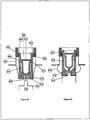
- Figure 2 illustrates a drug delivery device substantially similar to that of Figure 1 except that the inlet side of the moisture barrier is pierced with an external piercing device integrated into a plunger.
- Moisture barrier 201 is comprised of two layers of a moisture impervious material, typically a plastic coated foil. The top and bottom layers of foil are pre-formed to create moisture barrier 201 when attached together. Furthermore, the top layer has a formed step 208 that interfaces with outlet ring 203. Internal opening mechanism 202 resides within moisture barrier 201 and is integral with first chamber 209. The drug dose resides inside first chamber 209.
- First chamber 209 has multiple openings including air inlet 212 and outlet 211, which are in close proximity with the moisture barrier 201 when the package is assembled. There is a first cutting edge 206 at the outlet opening 211 in first chamber 209 and a second cutting edge 207 integrated into a protuberance on the plunger 205.
- the dose sealing system consists of the outlet ring 203, which provides annular pressure creating a tight seal 215 between internal opening mechanism 202 and moisture barrier 201 at first chamber outlet opening 211.
- the dose sealing system includes external annular ring (not shown) or interference fit 216 between moisture barrier 201 and internal opening mechanism 202.
- a dose metering system in the form of a screen 204.
- plunger 205 is moved toward outlet ring 203, which causes the plunger protuberance 207 to pierce moisture barrier 201 at inlet opening 212 proximate to first chamber 209.
- the plunger protuberance moves into first chamber 209 until the plunger shoulder 213 contacts the internal opening mechanism 202 at the inlet opening edge 214.
- the internal opening mechanism slides against moisture barrier 201, causing first cutting edge 206 to protrude through moisture barrier 201 at outlet opening 211.
- Moisture barrier 201 deforms 210 to allow the relative movement of plunger 205 and outlet ring 203.
- Air can be drawn through the open first chamber 209, possibly through plunger 205, entraining drug into the air stream.
- Drug metering system 204 prevents the drug from leaving the package as one large clump and helps fluidize the dose.
- the drug metering system may be outside of the first chamber, or may not be present in the package.
- the drug delivery device shown in Figures 1 and 2 can readily be used in active configurations such as spinning, vibration and forced airflow source. Spinning the drug delivery device about its long axis would serve the purpose of spreading the drug out against the first chamber walls, creating a large dose surface area to facilitate rapid metered fluidization. Similarly, vibration from an "Active" source would facilitate drug dispersion.
- the active vibration source could be a piezo-electric actuator or a motor.
- the active configuration alternatively could use an active air flow source such as compressed air or a fan. In this case, the entrained dose would likely be captured in a mixing chamber before being delivered to the patient.
- the mixing chamber could be a rigid vessel or a flexible design that inflates during use and collapses for storage.
- Figure 3 illustrates a device similar to that shown in Figure 2 except that a second chamber has been added to store the drug dose.
- the second chamber provides benefits including secure containment of the drug dose, ease of manufacturing and drug filling, and drug metering.
- the second chamber can move relative to the first chamber and has an open and closed position.
- plunger 305 pierces the moisture barrier and pushes against the second chamber causing it to slide from the closed position to the open position.
- Air flows through the plunger, around and through the second chamber and out the other side of the moisture barrier.
- Drug is entrained into the air path by venturi effect through openings in the second chamber.
- the airflow through and around the second chamber is managed by air channels formed by the first chamber and the second chamber.
- the air channels are shaped to create a restriction at the second chamber openings, increasing the air velocity, and creating the venturi effect.
- Moisture barrier 301 is formed of two layers of a moisture impervious material, typically a plastic coated foil. The top and bottom layers of foil are pre-formed to create moisture barrier 301 when attached together. One layer has a formed step 308 that interfaces with outlet ring 303.
- Internal opening mechanism 302 resides within moisture barrier 301 and creates first chamber 309.
- First chamber 309 has openings for air inlet 312 and outlet 311. Inlet 312 and outlet 311 are in close proximity with the moisture barrier 301 when the package is assembled.
- Second chamber 316 resides within first chamber 309 and contains the drug dose.
- Second chamber has a drug sealing system with openings 304 that are covered by interference with the internal opening mechanism 302 when the device is stored in its closed position.
- Second chamber 316 can be moved relative to first chamber 309 to eliminate the interference at the openings 304 to create a path between the first and second chambers.
- Integrated into second chamber 316 is a drug metering system in the form of one or more openings designed to fluidize powder in second chamber 316 and facilitate dose entrainment into the air path through first chamber 309 by venturi effect.
- Second chamber plug 317 is used to close an opening after filling second chamber 316 with drug during manufacturing.
- Air channels 318 direct airflow past second chamber openings 304 and through the device and are formed into the first chamber 309 and the walls of second chamber 316. These air channels 318 could also take the form of a nozzle or orifice.
- plunger 305 and outlet ring 303 are moved together, causing the protuberance on plunger 305 to pierce moisture barrier 301 at inlet opening 312 to first chamber 309.
- the protuberance on plunger 305 moves into first chamber 309 until plunger 305 contacts second chamber 316, causing it to open by movement from the closed to open position.
- the protuberance on plunger 305 continues to move into first chamber 309 until plunger shoulder 313 contacts internal opening mechanism 302 at the inlet opening edge 314.
- internal opening mechanism 302 slides against moisture barrier 301, causing first cutting edge 306 to protrude through moisture barrier 301 at outlet opening 311.
- Moisture barrier 301 deforms 310 to allow the relative movement of plunger 305 and outlet ring 303.
- Air can be drawn through the open first chamber 309, possibly through plunger 305, and around and through second chamber 316 to entrain drug into the air stream.
- Dose metering system 304 embodied by specific opening geometry in second chamber 316, prevents the drug from leaving the package as one large clump and helps fluidize the dose.
- This design could also be applied in a combination dose configuration where multiple drugs are delivered to the patient at the same time.
- the drugs need to be stored separately from each other and then combined at the time of inhalation. This can be accomplished by dividing second chamber 316 into multiple cavities, or by including multiple second chambers 316 within the device.
- Figure 4 illustrates a device similar to that shown in Figure 3 , except that the inhaler relies on an "Active" source for the air movement through the inhaler instead of the patient's inhaling capability.
- the entrained dose may be captured in a mixing chamber 419 before being delivered to the user.
- a mixing chamber may be required if the active air source is at a higher pressure or flow rate than would want to be delivered directly to the user.
- the active airflow source could be compressed air or a fan.
- the mixing chamber could be a rigid vessel or a flexible design that inflates during use and collapses for storage.
- the airflow may be through, or around, plunger 405.
- the other parts shown in Figure 4 are similar to those shown in Figure 3 .
- This design could also be applied in a combination dose configuration where multiple drugs are delivered to the patient at the same time.
- FIG. 5 illustrates a device similar that shown in Figure 3 except that second chamber 516 is designed to vibrate to assist in dose metering and evacuation.
- Second chamber 516 provides benefits including secure containment of the drug dose, ease of manufacturing and drug filling, and drug metering. Second chamber 516 can move relative to the first chamber 509. To open the package, plunger 505 pierces moisture barrier 501 and pushes against second chamber 516, causing it to slide from the closed position to the open position. Air flows through plunger 505, around and through second chamber 516 and out the other side of first chamber 509. Powder is entrained into the air path by vibration caused by the movement of air around second chamber 516. The airflow through and around second chamber 516 is controlled by air channels formed by the internal opening mechanism 502 and second chamber 516. Second chamber 516 may be held in position by a protruding tether that is in contact with internal opening mechanism 502.
- Moisture barrier 501 is comprised of two layers of a moisture impervious material, typically a plastic coated foil. The top and bottom layers of foil are pre-formed to create moisture barrier 501 when attached together. Furthermore, the top layer has a formed step 508 that interfaces with outlet ring 503. Internal opening mechanism 502 resides in moisture barrier 501 and creates first chamber 509.
- First chamber 509 has openings for air inlet 512 and outlet 511, which are in close proximity to moisture barrier 501 when the device is assembled. There is a first cutting edge 506 at outlet opening 511 in first chamber 509 and a second cutting edge 507 integrated into a protuberance on plunger 505.
- Second chamber 516 resides within first chamber 509 and contains the drug dose.
- Second chamber 516 contains a drug sealing system including openings 504 that are covered by interference fit with the first chamber 5099 when the device is in its closed position.
- Second chamber 516 can be moved relative to first chamber 509 to eliminate the interference at openings 504 to open the device and create a path between the first and second chambers.
- Second chamber 516 Also integrated into second chamber 516 is a drug metering system in the form of one or more openings designed to fluidize powder in second chamber 516 and facilitate drug entrainment by vibration and venturi effect into the air path through first chamber 509.
- Second chamber 516 has a protruding section 519 extending toward air path inlet 512 that attaches to the internal opening mechanism 502.
- Protruding portion or geometry 519 is the only point of contact with the internal opening mechanism 502 when second chamber 516 is in the open position.
- Protruding geometry 519 is shaped to allow second chamber 516 to vibrate in response to surrounding airflow turbulence.
- protruding geometry 519 may be a flexible beam (like a tuning fork tine) or a flexible tether (such as a string or chain).
- Second chamber plug 517 is used to close an opening after filling second chamber 516 with drug during manufacturing.
- plunger 505 and outlet ring 503 are moved together; causing protuberance 507 on plunger 505 to pierce moisture barrier 501 at the inlet opening 512 to first chamber 509.
- Protuberance 507 on plunger 505 moves into first chamber 509 until plunger 505 contacts second chamber 516, causing it to open by movement from the closed to open position.
- Protuberance 507 on plunger 505 continues to move into first chamber 509 until plunger shoulder 513 contacts internal opening mechanism 502 at the inlet opening edge 514.
- internal opening mechanism 502 slides against moisture barrier 501, causing cutting edge 506 to protrude through moisture barrier 501 at outlet opening 511.
- Moisture barrier 501 deforms 510 to allow the relative movement of plunger 505 and outlet ring 503.
- Air can be drawn through the open first chamber 509, possibly through plunger 505, and goes around and through second chamber 516, causing second chamber 516 to vibrate, and entraining drug into the air stream.
- This design could also be applied in a combination dose configuration where multiple drugs are delivered to the patient at the same time.
- the drugs need to be stored separately from each other and then combined at the time of inhalation. This can be accomplished by dividing second chamber 516 into multiple cavities, or by including multiple second chambers 516 within the device.
- Figure 6 is similar to the device described and illustrated in Figure 5 except that the inhaler relies on an "Active" source for vibration of the drug dose chamber instead of the patient's inhaling capability to activate the system.
- the active vibration source could be a piezo-electric actuator or a motor, possibly integrated with plunger 605.
- the active vibration source can couple to second chamber 616 at the plunger interface, internal opening mechanism 602, or a combination of the two.
- An alternate configuration would be to locate the vibration source inside moisture barrier 601.
- the vibration source could be a piezoelectric material, a specific component geometry that can be excited at target frequencies and amplitudes, or a magnetically coupled resonance receiver.
- the internal vibration source could be an independent component or be fully or partially integrated into internal opening mechanism 602, moisture barrier 601, second chamber 616 or a combination thereof.
- Electro-mechanical coupling can be accomplished by means of plunger 605, which makes contact with the internal vibration source after piercing moisture barrier 601.
- An alternate coupling scheme would allow electro-mechanical contact once the internal vibration source moved outside moisture barrier 601 and contacted the device during package opening.
- Coupling can also be achieved by making a non-physical electrical or magnetic connection with the internal vibration source, such as through inductive coupling.
- the active vibration configuration alternatively could use an active air flow source such as compressed air or a fan.
- the entrained dose would likely be captured in a mixing chamber (not shown) before being delivered to the patient.
- the mixing chamber could be a rigid vessel or a flexible design that inflates during use and collapses for storage.
- the active airflow through the package could be delivered through the plunger.
- This design could also be applied in a combination dose configuration where multiple drugs are delivered to the patient at the same time.
- Figure 7 is similar to the device described in conjunction with Figure 2 except that a second chamber has been added to store the drug dose.
- the second chamber provides benefits including secure containment of the drug dose, ease of manufacturing and drug filling, and drug metering into the air stream.
- the second chamber can move relative to the first chamber and has an open and closed position. To open the package, the plunger pierces the moisture barrier and pushes against the second chamber, causing it to slide from the closed position to the open position. Air may flow through the plunger, or around it, and possibly through the second chamber and out the other side of the moisture barrier. Powder exits through openings in the second chamber by a combination of tumbling, shaking and spinning, and is entrained into the air path.
- Powder may also exit the second chamber by venturi effect and/or by air flowing through the second chamber.
- the airflow around the second chamber may be managed by air channels formed by the first chamber.
- the air channels could be shaped to create a vortex or spinning of the air within the first chamber to facilitate tumbling and spinning of the second chamber.
- Moisture barrier 701 is comprised of two layers of a moisture impervious material, typically a plastic coated foil.
- the top and bottom layers of foil are pre-formed to create moisture barrier 701 when attached together.
- the top layer has a formed step 708 that interfaces with matching outlet ring geometry 703.
- An internal opening mechanism 702 resides in moisture barrier 701 and creates first chamber 709.
- First chamber 709 has openings for air inlet 712 and outlet 711, which are in close proximity with moisture barrier 701 when the device is assembled.
- Second chamber 716 resides within first chamber 709 and contains the drug dose.
- Second chamber 716 has a drug sealing system 704 with the openings in second chamber being covered by interference fit with first chamber 709 when the device is in its closed position.
- Second chamber 716 can be moved relative to first chamber 709 internal opening mechanism 702 to eliminate the interference at the openings and create a path between the first and second chambers.
- a drug metering system in the form of one or more openings designed to fluidize powder in second chamber 716 and facilitate drug entrainment, primarily by tumbling and spinning, into the air path through first chamber 709. These openings can be at any location in second chamber 716 as required to obtain the desired functionality.
- Chamber plug 717 is used to close an opening in second chamber 716 after filling with drug during manufacturing.
- plunger 705 and outlet ring 703 are moved together, which causes the protuberance on the plunger to pierce moisture barrier 701 at the inlet opening 712 to first chamber 709.
- Protuberance 707 on plunger 705 moves into first chamber 709 until plunger 705 contacts second chamber 716 causing it to open by movement from the closed to open position.
- Protuberance 707 on plunger 705 continues to move into first chamber 709 until plunger shoulder 713 contacts the internal opening mechanism 702 at the inlet opening edge 714.
- internal opening mechanism 702 slides against moisture barrier 701, causing cutting edge 706 to protrude through moisture barrier at outlet opening 711.
- Air can be drawn through the open first chamber 709, around and possibly through second chamber 716, tumbling or spinning second chamber 716 and entraining drug into the air stream.
- Mesh screen 719 restrains second chamber 716 within first chamber 709, and may also prevent the drug from leaving the package as one large clump.
- This design could also be applied in a combination dose configuration where multiple drugs are delivered to the patient at the same time.
- the drugs need to be stored separately from each other and then combined at the time of inhalation. This can be accomplished by dividing second chamber 716 into multiple cavities, or by including multiple second chambers within the device.
- the tumbling chamber drug package configuration can also be utilized in an active inhaler system.
- Figure 8 shows this configuration and its use is identical to that of Figure 7 , with the difference being that rather than relying on the patient's respiration for the air flow to create the tumbling action of second chamber 816, an active compressed air or impellor system could be used. This may be particularly helpful in cases where the patient's airflow rate capabilities are diminished due to medical conditions.
- an active airflow source it is envisioned that the entrained dose could be captured in a mixing chamber 820 before being delivered to the user.
- the mixing chamber could be a rigid vessel or a flexible design that inflates during use and collapses for storage.
- the airflow through the device can be delivered through, or around, plunger 805.
- This design could also be applied to a combination dose configuration where multiple drugs are delivered to the patient at the same time.
- Figure 9 illustrates a device similar to the device of Figure 2 , except that a second chamber 916 has been added to store the drug dose.
- Second chamber 916 provides benefits including secure containment of the drug dose, ease of manufacturing and drug filling, and drug metering into the air stream.
- Second chamber 916 can move relative to internal opening mechanism 902.
- plunger 905 pierces moisture barrier 901 and pushes against second chamber 916, causing it to slide from the closed position to the open position.
- Air may flow through plunger 905, and around and possibly through second chamber 916 and out the other side of moisture barrier. Powder exits through openings in second chamber 916 from the spinning action, and is entrained into the air path.
- Powder may also exit second chamber 916 by venturi effect and/or by air flowing through second chamber 916.
- the airflow around second chamber 916 may be directed or controlled by air channels formed by first chamber 909 internal opening mechanism 902.
- the air channels could be shaped to create a vortex or spinning of the air in first chamber 909 to facilitate spinning of second chamber 916.
- Moisture barrier 901 is comprised of two layers of a moisture impervious material, typically a plastic coated foil.
- the top and bottom layers of foil are pre-formed to create moisture barrier 901 when attached together.
- the top layer has a formed step 908 that interfaces with the geometry of matching outlet ring 903.
- First chamber 909 has openings for air inlet 912 and outlet 911, which are in close proximity with moisture barrier 901 when the device is assembled. There is a first cutting edge 906 at outlet opening 911 in first chamber 909 and a second cutting edge 907 integrated into a protuberance on the plunger 905.
- Second chamber 916 resides within first chamber 909 and contains the drug dose.
- Second chamber 916 has a drug sealing system 904, with the openings in second chamber 916 being covered by an interference fit with internal opening mechanism 902 when the device is in its closed position.
- Second chamber 916 can be moved relative to internal opening mechanism 902 to eliminate the interference at the openings and create a path between the first and second chambers.
- a drug metering system in the form of one or more openings designed to fluidize powder in second chamber 916 and facilitate drug entrainment, primarily by spinning, into the air path through first chamber 909.
- the openings can be in any location on second chamber 916.
- Chamber plug 917 is used to close an opening in second chamber 916 after filling with drug during manufacturing.
- plunger 905 is moved toward the outlet ring 903 which causes the cutting edge on the plunger protuberance to pierce moisture barrier 901 at inlet opening 912 to first chamber 909.
- the protuberance on plunger 905 moves into the first chamber 909 until plunger 905 contacts the second chamber 916 causing it to move from the closed to open position.
- the protuberance on plunger 905 continues to move into the first chamber 909 until plunger shoulder 913 contacts internal opening mechanism 902 at inlet opening edge 914.
- internal opening mechanism 902 slides against moisture barrier 901, causing cutting edge 906 to protrude through moisture barrier 901 at the outlet opening 911.
- Moisture barrier deforms 910 to allow the relative movement of outlet ring 903 and internal opening mechanism 902.
- Air can be drawn through the open first chamber 909, around and possibly through second chamber 916, spinning second chamber 916 and entraining drug into the air stream.
- Air inlets 918 can be configured to create a vortex within first chamber 909, which imparts a spinning action on second chamber 916.
- Second chamber 916 may have fins or other geometric details that are acted upon by the air to impart the spinning motion.
- Second chamber 916 is radially supported by first chamber 909 and a mesh screen 919 in order to guide the spinning motion. Mesh screen 919 also constrains second chamber 916 axially within first chamber 909, and may also prevent the drug from leaving the package as one large clump.
- This design could also be applied in a combination dose configuration where multiple drugs are delivered to the patient at the same time.
- the drugs need to be stored separately from each other and then combined at the time of inhalation. This can be accomplished by dividing the second chamber 916 into multiple cavities, or by including multiple second chambers within the device.
- the spinning chamber drug package configuration can also be utilized in an active inhaler system.
- Figure 10 shows this configuration and its use is identical to that of Figure 9 , with the difference being that rather than relying on the patient's respiration for the air flow to create the spinning action of second chamber 1016, an active compressed air or impellor system could be used. This may be particularly helpful in cases where the patient's air flow rate capabilities are diminished due to medical conditions.
- an active airflow source it is envisioned that the entrained dose could be captured in a mixing chamber 1020 before being delivered to the user.
- the mixing chamber could be a rigid vessel or a flexible design that inflates during use and collapses for storage.
- the airflow through the package can be delivered through, or around, plunger 1005.
- This design could also be applied in a combination dose configuration where multiple drugs are delivered to the patient at the same time.
- FIG 11 illustrates a drug delivery device with a movable internal opening mechanism 1102 that contains the drug dose.
- Internal opening mechanism 1102 is located inside the drug sealing system 1103.
- Drug sealing system 1103 is located within moisture barrier 1101 and is attached at seal 1114, at least in part, to moisture barrier.
- Internal opening mechanism 1102 can move relative to moisture barrier 1101 and drug sealing system 1103.
- Moisture barrier 1101 is opened when cutting edge 1105 on internal opening mechanism 1102 is pressed against moisture barrier 1101.
- the drug dose exits through an opening 1106 by centrifugal force as the package is rotated (spinning action) about a main axis of rotation 1107.
- powder may also exit the internal opening mechanism by a venturi effect and/or by air flowing through internal opening mechanism 1102.
- This configuration provides benefits including secure containment of the drug dose, ease of manufacturing and drug filling, and drug metering into the air stream.
- Moisture barrier 1101 is comprised of two layers of a moisture impervious material, typically a plastic coated foil. The top and bottom layers of foil may be pre-formed to create the moisture barrier 1101 when attached together.
- Drug sealing system 1103 resides within moisture barrier 1101 and may create a first chamber 1115.
- the internal opening mechanism 1102 resides within first chamber 1115, and forms second chamber 1109. The drug dose resides inside second chamber 1109.
- Second chamber 1109 has a plugged opening 1104 on one side for drug filling during manufacturing.
- the internal opening mechanism has a first cutting edge 1105 in close proximity to the foil of moisture barrier 1101.
- Internal opening mechanism 1102 creates a friction fit seal 1116 with drug sealing system 1103 to keep the drug from migrating out of second chamber 1109 prior to use.
- Drug sealing system 1103 may also extend around internal opening mechanism 1102 to guide its motion during opening of moisture barrier 1101.
- internal opening mechanism 1102 is moved relative to moisture barrier 1101 so that first cutting edge 1105 pierces moisture barrier 1101.
- the motion of internal opening mechanism 1102 is caused by spinning the packaging device, creating centrifugal force which moves internal opening mechanism 1102 away from the axis of revolution 1107.
- the patient's inspiratory airflow would be used to spin the packaging device.
- the spinning can be accomplished by means of an active spinning source 1108, such as a motor.
- An active configuration allows for stable control of rotational speed, and can provide higher opening speeds which allows thicker, formable foils to be used.
- the speed at which piercing occurs can be controlled by a variety of factors, including the mass of internal opening mechanism 1102 and contained drug, the distance of the center of this mass from the axis of revolution 1107, the thickness of the moisture barrier 1101 foil layer, and the geometry of first cutting edge 1105.
- the ability to dictate the piercing speed has a number of potential benefits.
- the rotational speed at packaging device opening can be used to ensure that a minimum inspiratory flow rate is met prior to packaging device opening.
- specific package opening speeds may allow for control of powder dispersion out of second chamber 1109 at predetermined rates.
- the drug dose exits second chamber 1109 and is entrained in the air flow by means of centrifugal force.
- the rate of drug metering out of the packaging device can be controlled by means of the geometry of opening 1106 in internal opening mechanism 1102 as well as by the speed of rotation. It is envisioned that the drug dose may enter a mixing chamber 1112 before being delivered to the user. The drug exits mixing chamber 1112 through outlet mouthpiece 1113.
- Piercing of moisture barrier 1101 by internal opening mechanism 1102 can also be achieved by means of an actuating mechanism 1110 rather than relying on centrifugal force caused by spinning of the device. This may be particularly useful in a passive system where it may be difficult to achieve high rotational speeds using the patient's inspiratory airflow alone.
- This design could also be applied to a combination dose configuration where multiple drugs are delivered to the patient at the same time.
- Figure 12 illustrates a multi-dose drug delivery device that integrates the systems illustrated in Figures 1 - 11 and 13-14 and has the benefit of packaging multiple doses into a single dispensing system to simplify the user experience.
- the dose packaging is manufactured in strips made up of multiple, factory pre-metered unit-doses 1204 that are positioned in a circular array and mounted between a two-piece clamshell cassette 1203.
- the dose packaging can be color coded to help identify drug type and dose strength.
- a plunger 1205 is located at the center of cassette 1203 and has an outward motion during unit-dose packaging device opening.
- a mouthpiece 1206 is located on the outside of cassette 1203 and is aligned with the central axis of the first unit-dose 1212.
- a mouthpiece cover 1202 is attached to a mechanism 1213 designed to actuate plunger 1205, advance drug cassette 1203 and advance dose counter 1207.
- mouthpiece cover 1202 to operate the multi-dose inhaler the user rotates mouthpiece cover 1202 from the closed position 1208 to a first position 1209, exposing mouthpiece 1206. The user then rotates mouthpiece cover 1202 to a second position 1210. This motion 1211 drives plunger 1205 in a radial direction, opening the unit-dose package 1204 that is aligned with plunger axis 1212. Plunger 1205 may be connected to mouthpiece cover 1202 by a mechanical linkage, or, alternatively, there may be a separate mechanism that causes the motion of the plunger that is not tied to the mouthpiece cover.
- the user inhales to administer the drug dose, and then moves mouthpiece cover 1202 back to closed position 1208.
- the action of closing the mouthpiece cover advances unit-dose cassette 1203 to the second unit-dose position and advances dose counter 1207 by one number.
- the multi-dose inhaler design also integrates a dose readiness indicator.
- the internal opening mechanism inside each dose package can be color coded for visibility. As each dose package is opened the internal opening mechanism is exposed and can be made visible to the user by means of a window in the cassette. Exposed color (green) can indicate that the dose is ready for inhalation.
- Dose cassettes 1203 can be designed to be replaceable.
- the user can load cassettes with specific drug dose therapies by opening the cassette and replacing spent doses in a reusable configuration.
- Figures 13A and 13B show a drug delivery system of the invention using a shaped dose metering system to assist in dispersing the medicine into the air path.
- Figure 13A shows the device in the closed position while Figure 13B shows it in the open position.
- the drug delivery system includes a first chamber, an opening device, and a dose metering system.
- First chamber 1301 is comprised of two layers of material, typically a plastic. The top and bottom layers are pre-formed to create an air path 1302 when attached together.
- a dose metering system 1303 is formed into the walls of first chamber 1301 to assist in drug dispersion.
- the drug resides in a reservoir 1304 in proximity to dose metering system 1303 when the device is closed and the drug is dispersed into the air path after opening the device.
- Dose metering system 1303 is in the form of a geometry designed to divert, deflect or direct some portion of airflow from the first chamber into reservoir 1304.
- Reservoir 1304 is shaped to receive airflow diverted from the air path 1302 through first chamber 1301, causing the medicine to fiuidize and move about reservoir 1304.
- First chamber 1301 has air inlet 1305 and air outlet 1306, which are closed by barriers 1307 when the device is assembled.
- the airflow is managed by air channels formed by the first chamber and the geometry enclosing the air path.
- An opening mechanism punctures barriers 1307 to open the air pathway 1302. Air can be drawn through open air pathway 1302, and possibly through the opening mechanism, thereby entraining drug into the air stream. Dose metering system 1303 facilitates fluidization and dispersion of the drug.
- Dose metering system 1303 includes a shaped opening 1308.
- Shaped opening 1308 has a geometry designed to control the movement of airflow in, out and around reservoir 1304 as air moves along air path 1302.
- the drug delivery device shown in Figures 13A and 13B can readily be used in active configurations such as vibration and forced airflow source. Vibration from an "Active" source would facilitate drug dispersion.
- the active vibration source could be a piezo-electric actuator or a motor.
- the active configuration alternatively could use an active air flow source such as compressed air or a fan. In this case, the entrained dose would likely be captured in a mixing chamber before being delivered to the patient.
- the mixing chamber could be a rigid vessel or a flexible design that inflates during use and collapses for storage.
- This design could also be applied in a combination dose configuration where multiple drugs are delivered to the patient at the same time.
- the drugs need to be stored separately from each other and then combined at the time of inhalation. This can be accomplished by dividing reservoir 1304 into multiple cavities, or by including multiple reservoirs 1304 within the device.
- a drug delivery device is contemplated that is similar to that of Figure 13 except that the geometry of opening mechanism 1402 defines a portion of first chamber 1403 and air path 1401. Opening mechanism 1402 is movable from a closed position to an open position and is movable relative to reservoir 1404. This configuration provides benefits including secure containment of the drug.
- First chamber 1403 is comprised of two parts and typically is made of plastic. In the contemplated embodiment, opening mechanism 1402 and first chamber 1403 are pre-formed to create a closed air path 1401. Air path 1401 has openings for air inlet 1407 and outlet 1408.
- Opening mechanism 1402 contains the drug dose. Opening mechanism 1402 includes a drug sealing system 1405 that covers the opening to reservoir 1404 by interference fit when the device is stored in the closed position. Opening mechanism 1402 can be moved relative to reservoir 1404 to eliminate the interference at the opening to create an air path between first chamber 1403 and reservoir 1404. Integrated into first chamber 1403 is a drug metering system 1406 in the form of one or more shaped openings designed to fluidize powder in reservoir 1404 and facilitate drug entrainment into air path 1401.
- Air path 1401 directs airflow past drug metering system 1406 and through the device.
- the air path can be shaped to create a restriction at the drug metering system, increasing velocity, and thereby increasing the effect of drug metering system 1406.
- Drug metering system 1406 is shaped to divert airflow into, and/or out of reservoir 1404, fluidizing the drug. Drug is entrained from the reservoir into the airflow by a combination of venturi effect, centrifugal force and turbulence created at the opening to the reservoir.
- opening mechanism 1402 is moved from the closed position to the open position. This action opens air path 1401 through first chamber 1403. This action also moves integral dose sealing system 1405 which opens up an air path between first chamber 1403 and reservoir 1404.
- Air can be drawn through inlet opening 1407, through air path 1401, across drug metering system 1406 and out outlet opening 1408, entraining drug into the air stream.
- This design could also be applied in a combination dose configuration where multiple drugs are delivered to the patient at the same time.
- the drugs need to be stored separately from each other and then combined at the time of inhalation. This can be accomplished by dividing reservoir 1404 into multiple cavities, or by including multiple reservoirs 1404 within the device.
- the drug delivery device can readily be used in active configurations such as vibration and forced airflow source. Vibration from an "Active" source would facilitate drug dispersion.
- the active vibration source could be a piezo-electric actuator or a motor.
- the active configuration alternatively could use an active air flow source such as compressed air or a fan. In this case, the entrained dose would likely be captured in a mixing chamber before being delivered to the patient.
- the mixing chamber could be a rigid vessel or a flexible design that inflates during use and collapses for storage.
- the system of the present invention provides significant advantages not seen in the prior art.
- the system provides a sealed, protected environment for a substance and prevents exposure of the substance from degrading elements for an extended period of time.
- the system can provide a moisture-impervious environment for moisture-sensitive substances, such as medicines in powdered form.
- the use of an integrated, internal puncturing mechanism facilitates release of the substance from the packaging device without relying on external components.
- the puncturing mechanism may be easily actuated, for example, by sliding the puncturing mechanism (i.e., the tube) within the internal chamber of the packaging device or a plunger may be used.
- the components of the packaging device are designed for manufacturability and the packaging device may be assembled and filled quickly and efficiently.
- the integrated puncturing mechanism provides a clear, unobstructed path for the substance stored in the packaging device to exit and reduces the number of dead spots or edges that trap the substance, a feature common in capsules that utilize external puncturing mechanisms. Moreover, the ability to create an air path through an internal chamber of a packaging device allows direct delivery of the substance, without requiring transfer of the substance to a separate delivery chamber. The integrated puncturing mechanism facilitates complete evacuation of all of the substance from the packaging device interior, resulting in more accurate dosing, increased safety and reduced waste.
Landscapes
- Health & Medical Sciences (AREA)
- Engineering & Computer Science (AREA)
- Life Sciences & Earth Sciences (AREA)
- Anesthesiology (AREA)
- General Health & Medical Sciences (AREA)
- Biomedical Technology (AREA)
- Heart & Thoracic Surgery (AREA)
- Hematology (AREA)
- Bioinformatics & Cheminformatics (AREA)
- Animal Behavior & Ethology (AREA)
- Veterinary Medicine (AREA)
- Public Health (AREA)
- Pulmonology (AREA)
- Biophysics (AREA)
- Chemical & Material Sciences (AREA)
- Dispersion Chemistry (AREA)
- Pharmacology & Pharmacy (AREA)
- Medical Preparation Storing Or Oral Administration Devices (AREA)
Claims (15)
- Système d'administration de médicament comprenant :une chambre (1301) incluant une entrée d'air (1305) et une sortie d'air (1306) et définissant un trajet d'air (1302) de l'entrée d'air (1305) à la sortie d'air (1306) ;un système de dosage (1303), etun réservoir (1304) à proximité du système de dosage (1303) et configuré pour conserver un médicament devant être dispersé dans le trajet d'air (1302) ; caractérisé en ce quele système de dosage (1303) est formé dans les parois de la chambre (1301) pour aider à la dispersion de médicament dans le trajet d'air (1302) ;dans lequel le système de dosage (1303) est conçu pour dévier, détourner ou diriger au moins une partie du flux d'air de la chambre (1301) dans le réservoir (1304).
- Système d'administration de médicament selon la revendication 1, dans lequel le système de dosage (1303) est sous la forme d'une géométrie conçue pour contrôler le mouvement du flux d'air à l'intérieur, en dehors et autour du réservoir (1304) lorsque l'air se déplace le long du trajet d'air (1302).
- Système d'administration de médicament selon les revendications 1 ou 2, dans lequel le trajet d'air (1302) peut être ouvert.
- Système d'administration de médicament selon les revendications 1 ou 2, incluant en outre une barrière (1307) fermant l'entrée d'air (1305) et la sortie d'air (1306) jusqu'à ce que le trajet d'air (1302) soit ouvert.
- Système d'administration de médicament selon les revendications 1 ou 2, comprenant en outre un mécanisme d'ouverture mobile d'une position fermée à une position ouverte pour former le trajet d'air (1302).
- Système d'administration de médicament selon la revendication 5, dans lequel le mécanisme d'ouverture inclut un système de fermeture étanche de médicament qui couvre une ouverture vers le réservoir (1304) lorsqu'il est dans la position fermée.
- Système d'administration de médicament selon la revendication 5, dans lequel le mécanisme d'ouverture définit une partie de la chambre (1301) et du trajet d'air (1302).
- Système d'administration de médicament selon l'une quelconque des revendications 1-7, dans lequel le système de dosage (1303) inclut une ouverture façonnée (1308) pour contrôler le mouvement du flux d'air lorsque l'air se déplace le long du trajet d'air (1302).
- Système d'administration de médicament selon la revendication 8, dans lequel le système de dosage (1303) inclut un bord formant l'ouverture façonnée (1308).
- Système d'administration de médicament selon l'une quelconque des revendications 1-9, dans lequel le réservoir (1304) inclut une configuration de dose de combinaison pour l'administration de multiples médicaments en même temps.
- Système d'administration de médicament selon l'une quelconque des revendications 1-10, dans lequel la chambre (1301) est façonnée pour créer une restriction dans le trajet d'air (1302) au niveau du système de dosage.
- Procédé d'administration de médicament comprenant :le confinement d'un médicament dans un réservoir (1304) d'un dispositif d'administration de médicament ;l'ouverture d'un trajet d'air (1302) à travers une chambre (1301) dans le dispositif d'administration de médicament, dans lequel le trajet d'air (1302) s'étend d'une entrée d'air (1305) à une sortie d'air (1306) ;le fait d'amener un flux d'air le long du trajet d'air (1302) de l'entrée d'air (1305) à la sortie d'air (1306) ;caractérisé parla déviation d'au moins une partie du flux d'air à travers le trajet d'air (1302) de la chambre (1301) dans le réservoir (1304) lorsque le flux d'air se déplace le long du trajet d'air (1302) ; etla réception du flux d'air dévié du trajet d'air (1302) dans le réservoir (1304) et le fait d'amener le médicament à se fluidifier, entraînant ainsi le médicament dans le flux d'air.
- Procédé d'administration de médicament selon la revendication 12, dans lequel le fait de confiner le médicament dans le réservoir (1304) inclut la fermeture étanche du réservoir (1304) par des barrières (1307) couvrant l'entrée d'air (1305) et la sortie d'air (1306) ou par un système de fermeture étanche de médicament qui couvre une ouverture vers le réservoir (1304).
- Procédé d'administration de médicament selon la revendication 12, dans lequel l'ouverture du trajet d'air (1302) dans le dispositif d'administration de médicament inclut la perforation de barrières (1307) fermant l'entrée d'air (1305) et la sortie d'air (1306) ou le déplacement d'un mécanisme d'ouverture d'une position fermée à une position ouverte pour former le trajet d'air (1302).
- Procédé d'administration de médicament selon l'une quelconque des revendications 12-14, dans lequel la partie du flux d'air est déviée à travers une ouverture façonnée (1308) présentant une géométrie conçue pour contrôler le mouvement du flux d'air à l'intérieur, en dehors et autour du réservoir (1304) lorsque l'air se déplace le long du trajet d'air (1302).
Applications Claiming Priority (4)
| Application Number | Priority Date | Filing Date | Title |
|---|---|---|---|
| US70094705P | 2005-07-20 | 2005-07-20 | |
| US70303205P | 2005-07-27 | 2005-07-27 | |
| EP05812327.4A EP1917057A4 (fr) | 2005-07-20 | 2005-10-21 | Dispositif d'inhalation |
| PCT/US2005/038147 WO2007018568A1 (fr) | 2005-07-20 | 2005-10-21 | Dispositif d’inhalation |
Related Parent Applications (2)
| Application Number | Title | Priority Date | Filing Date |
|---|---|---|---|
| EP05812327.4A Division EP1917057A4 (fr) | 2005-07-20 | 2005-10-21 | Dispositif d'inhalation |
| EP05812327.4A Division-Into EP1917057A4 (fr) | 2005-07-20 | 2005-10-21 | Dispositif d'inhalation |
Publications (2)
| Publication Number | Publication Date |
|---|---|
| EP2957312A1 EP2957312A1 (fr) | 2015-12-23 |
| EP2957312B1 true EP2957312B1 (fr) | 2019-12-04 |
Family
ID=37727619
Family Applications (2)
| Application Number | Title | Priority Date | Filing Date |
|---|---|---|---|
| EP14198194.4A Active EP2957312B1 (fr) | 2005-07-20 | 2005-10-21 | Dispositif d'inhalation |
| EP05812327.4A Withdrawn EP1917057A4 (fr) | 2005-07-20 | 2005-10-21 | Dispositif d'inhalation |
Family Applications After (1)
| Application Number | Title | Priority Date | Filing Date |
|---|---|---|---|
| EP05812327.4A Withdrawn EP1917057A4 (fr) | 2005-07-20 | 2005-10-21 | Dispositif d'inhalation |
Country Status (3)
| Country | Link |
|---|---|
| EP (2) | EP2957312B1 (fr) |
| DK (1) | DK2957312T3 (fr) |
| WO (1) | WO2007018568A1 (fr) |
Families Citing this family (21)
| Publication number | Priority date | Publication date | Assignee | Title |
|---|---|---|---|---|
| EP1844806A1 (fr) | 2006-04-13 | 2007-10-17 | Boehringer Ingelheim Pharma GmbH | Distributeur de medicaments, magasin de medicaments pour ledit distributeur, et procédé de prélèvement de médicament d'un réservoir |
| EP1992375A1 (fr) * | 2007-05-16 | 2008-11-19 | Boehringer Ingelheim Pharma GmbH & Co. KG | Dispositif distributeur |
| EP1992379A1 (fr) | 2007-05-16 | 2008-11-19 | Boehringer Ingelheim Pharma GmbH & Co. KG | Dispositif distributeur |
| EP1992380A1 (fr) * | 2007-05-16 | 2008-11-19 | Boehringer Ingelheim Pharma GmbH & Co. KG | Dispositif distributeur |
| EP1992374A1 (fr) * | 2007-05-16 | 2008-11-19 | Boehringer Ingelheim Pharma GmbH & Co. KG | Dispositif distributeur |
| EP1992373A1 (fr) | 2007-05-16 | 2008-11-19 | Boehringer Ingelheim Pharma GmbH & Co. KG | Dispositif distributeur |
| EP1992377A1 (fr) | 2007-05-16 | 2008-11-19 | Boehringer Ingelheim Pharma GmbH & Co. KG | Dispositif distributeur |
| EP1992376A1 (fr) * | 2007-05-16 | 2008-11-19 | Boehringer Ingelheim Pharma GmbH & Co. KG | Dispositif distributeur |
| EP1992372A1 (fr) | 2007-05-16 | 2008-11-19 | Boehringer Ingelheim Pharma GmbH & Co. KG | Dispositif de distribution |
| EP1992378A1 (fr) * | 2007-05-16 | 2008-11-19 | Boehringer Ingelheim Pharma GmbH & Co. KG | Dispositif distributeur |
| EP1992381A1 (fr) * | 2007-05-16 | 2008-11-19 | Boehringer Ingelheim Pharma GmbH & Co. KG | Dispositif distributeur |
| BRPI1009072B1 (pt) | 2009-05-18 | 2021-06-22 | Adamis Pharmaceuticals Corporation | Dispositivo para inalação de pó seco e dispositivo para armazenamento de pó seco |
| PL2654864T3 (pl) | 2010-12-22 | 2021-07-12 | Syqe Medical Ltd. | System dostarczania leku |
| ES2877100T3 (es) | 2011-07-13 | 2021-11-16 | Pharmaxis Ltd | Mejoras relacionadas con los dispositivos de suministro |
| CA2841398C (fr) * | 2011-07-13 | 2020-07-14 | Pharmaxis Ltd | Un dispositif de distribution renfermant un contenant autonome |
| AU2017204945B2 (en) | 2016-01-06 | 2022-11-10 | Syqe Medical Ltd. | Low dose therapeutic treatment |
| US11690964B2 (en) | 2017-05-31 | 2023-07-04 | Virginia Commonwealth University | Devices, systems, and methods for dry powder therapies |
| EP4176912A3 (fr) * | 2018-10-02 | 2023-08-02 | Boston Scientific Scimed, Inc. | Dispositifs de fluidisation et de distribution d'un agent en poudre |
| JP7467442B2 (ja) * | 2018-10-28 | 2024-04-15 | サイケ メディカル リミテッド | カートリッジユニットカップラ |
| CN109464743A (zh) * | 2018-12-12 | 2019-03-15 | 江苏美德愈医疗科技有限公司 | 糖尿病足创面治疗装置用分气装置 |
| US20220379051A1 (en) * | 2019-10-25 | 2022-12-01 | Philip Morris Products S.A. | Inhaler article with open distal end, and inhaler system |
Citations (7)
| Publication number | Priority date | Publication date | Assignee | Title |
|---|---|---|---|---|
| US2590832A (en) * | 1949-03-29 | 1952-03-25 | Frederick M Turnbull | Inhaler with closure |
| US2603216A (en) * | 1952-07-15 | Powder inhaler | ||
| WO1990007351A1 (fr) * | 1989-01-06 | 1990-07-12 | Hans Gernot Schenk | Inhalateur oral |
| US6595203B1 (en) * | 2000-11-28 | 2003-07-22 | Forrest M. Bird | Apparatus for administering intermittent percussive ventilation and unitary breathing head assembly for use therein |
| US6655381B2 (en) * | 2000-06-23 | 2003-12-02 | Ivax Corporation | Pre-metered dose magazine for breath-actuated dry powder inhaler |
| US6722364B2 (en) * | 2001-01-12 | 2004-04-20 | Becton, Dickinson And Company | Medicament inhalation delivery devices and methods for using the same |
| US20040206773A1 (en) * | 2001-08-16 | 2004-10-21 | Ede Andrew John | Pack containing medicament and dispensing device |
Family Cites Families (20)
| Publication number | Priority date | Publication date | Assignee | Title |
|---|---|---|---|---|
| US1410556A (en) | 1919-03-07 | 1922-03-28 | Frank C Dorment | Inhaler |
| US3888253A (en) * | 1972-08-04 | 1975-06-10 | Beecham Group Ltd | Device for administration of medicines |
| GB1561835A (en) * | 1976-02-11 | 1980-03-05 | Allen & Hanburys Ltd | Devices for dispensing medicamtens |
| IT1116047B (it) * | 1979-04-27 | 1986-02-10 | Sigma Tau Ind Farmaceuti | Dispositivo per la rapida inalazione di farmaci in polvere da parte di persone sofferenti di asma |
| US4706663A (en) * | 1986-04-25 | 1987-11-17 | Makiej Paul A | Particle catcher for inhalation devices |
| FR2667509B1 (fr) * | 1990-10-04 | 1995-08-25 | Valois | Inhalateur a poudre, dispositif de conditionnement de microdoses de poudre sous forme de bandes adaptees a etre utilisees dans un inhalateur a poudre, et procede de fabrication de ces bandes. |
| US5239993A (en) * | 1992-08-26 | 1993-08-31 | Glaxo Inc. | Dosage inhalator providing optimized compound inhalation trajectory |
| SE9302550D0 (sv) * | 1993-07-30 | 1993-07-30 | Ernst Hoerlin | Powder inhaler |
| US6209538B1 (en) * | 1995-08-02 | 2001-04-03 | Robert A. Casper | Dry powder medicament inhalator having an inhalation-activated flow diverting means for triggering delivery of medicament |
| US5823183A (en) * | 1995-08-02 | 1998-10-20 | Innovative Devices | Dry powder medicament inhalator having an inhalation-activated flow diverting means for triggering delivery of medicament |
| DE19704849B4 (de) * | 1997-02-08 | 2011-02-17 | Ing. Erich Pfeiffer Gmbh | Austragvorrichtung für Medien |
| US6006747A (en) * | 1997-03-20 | 1999-12-28 | Dura Pharmaceuticals, Inc. | Dry powder inhaler |
| US6234169B1 (en) * | 1998-08-14 | 2001-05-22 | Arthur Slutsky | Inhaler |
| FI108518B (fi) * | 1999-04-23 | 2002-02-15 | Orion Yhtymae Oyj | Jauheinhalaattori yhdistelmälääkkeelle |
| US6971383B2 (en) * | 2001-01-24 | 2005-12-06 | University Of North Carolina At Chapel Hill | Dry powder inhaler devices, multi-dose dry powder drug packages, control systems, and associated methods |
| US20020020408A1 (en) * | 2000-05-25 | 2002-02-21 | Invivotech, Inc. | Inhalation medicament delivery device |
| US6443152B1 (en) * | 2001-01-12 | 2002-09-03 | Becton Dickinson And Company | Medicament respiratory delivery device |
| US20040065324A1 (en) * | 2002-10-08 | 2004-04-08 | Pivinski Daniel Kozak | Thermal inhaler |
| US20040206350A1 (en) * | 2002-12-19 | 2004-10-21 | Nektar Therapeutics | Aerosolization apparatus with non-circular aerosolization chamber |
| GB2405798A (en) * | 2003-09-15 | 2005-03-16 | Vectura Ltd | Dry powder inhaler with primary and secondary piercing elements and a medicament pack for use with an inhalation device. |
-
2005
- 2005-10-21 WO PCT/US2005/038147 patent/WO2007018568A1/fr active Application Filing
- 2005-10-21 EP EP14198194.4A patent/EP2957312B1/fr active Active
- 2005-10-21 EP EP05812327.4A patent/EP1917057A4/fr not_active Withdrawn
- 2005-10-21 DK DK14198194.4T patent/DK2957312T3/da active
Patent Citations (7)
| Publication number | Priority date | Publication date | Assignee | Title |
|---|---|---|---|---|
| US2603216A (en) * | 1952-07-15 | Powder inhaler | ||
| US2590832A (en) * | 1949-03-29 | 1952-03-25 | Frederick M Turnbull | Inhaler with closure |
| WO1990007351A1 (fr) * | 1989-01-06 | 1990-07-12 | Hans Gernot Schenk | Inhalateur oral |
| US6655381B2 (en) * | 2000-06-23 | 2003-12-02 | Ivax Corporation | Pre-metered dose magazine for breath-actuated dry powder inhaler |
| US6595203B1 (en) * | 2000-11-28 | 2003-07-22 | Forrest M. Bird | Apparatus for administering intermittent percussive ventilation and unitary breathing head assembly for use therein |
| US6722364B2 (en) * | 2001-01-12 | 2004-04-20 | Becton, Dickinson And Company | Medicament inhalation delivery devices and methods for using the same |
| US20040206773A1 (en) * | 2001-08-16 | 2004-10-21 | Ede Andrew John | Pack containing medicament and dispensing device |
Also Published As
| Publication number | Publication date |
|---|---|
| EP1917057A1 (fr) | 2008-05-07 |
| WO2007018568A1 (fr) | 2007-02-15 |
| EP2957312A1 (fr) | 2015-12-23 |
| DK2957312T3 (da) | 2020-03-02 |
| EP1917057A4 (fr) | 2017-05-03 |
Similar Documents
| Publication | Publication Date | Title |
|---|---|---|
| US11491287B2 (en) | Inhalation device | |
| EP2957312B1 (fr) | Dispositif d'inhalation | |
| US8627818B2 (en) | Sealed capsule including an integrated puncturing mechanism | |
| US10434267B2 (en) | Inhalation device and method | |
| US9339616B2 (en) | Dry powder inhalers | |
| EP2432536B1 (fr) | Système de cassette rotative pour inhalateur de poudre sèche | |
| RU2332240C2 (ru) | Магазин-дозатор с предварительным отмериванием для ингалятора сухого порошкообразного средства | |
| US20060021616A1 (en) | Inhaler | |
| US5692496A (en) | Dry powder medicament inhalator having an inhalation-activated flow diverting means for triggering delivery of medicament | |
| US20080283058A1 (en) | Inhaler |
Legal Events
| Date | Code | Title | Description |
|---|---|---|---|
| PUAI | Public reference made under article 153(3) epc to a published international application that has entered the european phase |
Free format text: ORIGINAL CODE: 0009012 |
|
| AC | Divisional application: reference to earlier application |
Ref document number: 1917057 Country of ref document: EP Kind code of ref document: P |
|
| AK | Designated contracting states |
Kind code of ref document: A1 Designated state(s): AT BE BG CH CY CZ DE DK EE ES FI FR GB GR HU IE IS IT LI LT LU LV MC NL PL PT RO SE SI SK TR |
|
| 17P | Request for examination filed |
Effective date: 20160616 |
|
| RBV | Designated contracting states (corrected) |
Designated state(s): AT BE BG CH CY CZ DE DK EE ES FI FR GB GR HU IE IS IT LI LT LU LV MC NL PL PT RO SE SI SK TR |
|
| STAA | Information on the status of an ep patent application or granted ep patent |
Free format text: STATUS: EXAMINATION IS IN PROGRESS |
|
| 17Q | First examination report despatched |
Effective date: 20180208 |
|
| GRAP | Despatch of communication of intention to grant a patent |
Free format text: ORIGINAL CODE: EPIDOSNIGR1 |
|
| STAA | Information on the status of an ep patent application or granted ep patent |
Free format text: STATUS: GRANT OF PATENT IS INTENDED |
|
| RIC1 | Information provided on ipc code assigned before grant |
Ipc: A61M 11/00 20060101AFI20190522BHEP Ipc: A61M 11/02 20060101ALN20190522BHEP Ipc: A61M 15/00 20060101ALI20190522BHEP |
|
| INTG | Intention to grant announced |
Effective date: 20190612 |
|
| GRAS | Grant fee paid |
Free format text: ORIGINAL CODE: EPIDOSNIGR3 |
|
| GRAA | (expected) grant |
Free format text: ORIGINAL CODE: 0009210 |
|
| STAA | Information on the status of an ep patent application or granted ep patent |
Free format text: STATUS: THE PATENT HAS BEEN GRANTED |
|
| AC | Divisional application: reference to earlier application |
Ref document number: 1917057 Country of ref document: EP Kind code of ref document: P |
|
| AK | Designated contracting states |
Kind code of ref document: B1 Designated state(s): AT BE BG CH CY CZ DE DK EE ES FI FR GB GR HU IE IS IT LI LT LU LV MC NL PL PT RO SE SI SK TR |
|
| REG | Reference to a national code |
Ref country code: GB Ref legal event code: FG4D |
|
| REG | Reference to a national code |
Ref country code: CH Ref legal event code: EP |
|
| REG | Reference to a national code |
Ref country code: AT Ref legal event code: REF Ref document number: 1208611 Country of ref document: AT Kind code of ref document: T Effective date: 20191215 |
|
| REG | Reference to a national code |
Ref country code: DE Ref legal event code: R096 Ref document number: 602005056472 Country of ref document: DE |
|
| REG | Reference to a national code |
Ref country code: IE Ref legal event code: FG4D |
|
| REG | Reference to a national code |
Ref country code: DK Ref legal event code: T3 Effective date: 20200225 |
|
| REG | Reference to a national code |
Ref country code: SE Ref legal event code: TRGR |
|
| REG | Reference to a national code |
Ref country code: NL Ref legal event code: FP |
|
| REG | Reference to a national code |
Ref country code: LT Ref legal event code: MG4D |
|
| PG25 | Lapsed in a contracting state [announced via postgrant information from national office to epo] |
Ref country code: LV Free format text: LAPSE BECAUSE OF FAILURE TO SUBMIT A TRANSLATION OF THE DESCRIPTION OR TO PAY THE FEE WITHIN THE PRESCRIBED TIME-LIMIT Effective date: 20191204 Ref country code: BG Free format text: LAPSE BECAUSE OF FAILURE TO SUBMIT A TRANSLATION OF THE DESCRIPTION OR TO PAY THE FEE WITHIN THE PRESCRIBED TIME-LIMIT Effective date: 20200304 Ref country code: FI Free format text: LAPSE BECAUSE OF FAILURE TO SUBMIT A TRANSLATION OF THE DESCRIPTION OR TO PAY THE FEE WITHIN THE PRESCRIBED TIME-LIMIT Effective date: 20191204 Ref country code: LT Free format text: LAPSE BECAUSE OF FAILURE TO SUBMIT A TRANSLATION OF THE DESCRIPTION OR TO PAY THE FEE WITHIN THE PRESCRIBED TIME-LIMIT Effective date: 20191204 Ref country code: GR Free format text: LAPSE BECAUSE OF FAILURE TO SUBMIT A TRANSLATION OF THE DESCRIPTION OR TO PAY THE FEE WITHIN THE PRESCRIBED TIME-LIMIT Effective date: 20200305 |
|
| PG25 | Lapsed in a contracting state [announced via postgrant information from national office to epo] |
Ref country code: PT Free format text: LAPSE BECAUSE OF FAILURE TO SUBMIT A TRANSLATION OF THE DESCRIPTION OR TO PAY THE FEE WITHIN THE PRESCRIBED TIME-LIMIT Effective date: 20200429 Ref country code: ES Free format text: LAPSE BECAUSE OF FAILURE TO SUBMIT A TRANSLATION OF THE DESCRIPTION OR TO PAY THE FEE WITHIN THE PRESCRIBED TIME-LIMIT Effective date: 20191204 Ref country code: RO Free format text: LAPSE BECAUSE OF FAILURE TO SUBMIT A TRANSLATION OF THE DESCRIPTION OR TO PAY THE FEE WITHIN THE PRESCRIBED TIME-LIMIT Effective date: 20191204 Ref country code: CZ Free format text: LAPSE BECAUSE OF FAILURE TO SUBMIT A TRANSLATION OF THE DESCRIPTION OR TO PAY THE FEE WITHIN THE PRESCRIBED TIME-LIMIT Effective date: 20191204 Ref country code: EE Free format text: LAPSE BECAUSE OF FAILURE TO SUBMIT A TRANSLATION OF THE DESCRIPTION OR TO PAY THE FEE WITHIN THE PRESCRIBED TIME-LIMIT Effective date: 20191204 |
|
| PG25 | Lapsed in a contracting state [announced via postgrant information from national office to epo] |
Ref country code: SK Free format text: LAPSE BECAUSE OF FAILURE TO SUBMIT A TRANSLATION OF THE DESCRIPTION OR TO PAY THE FEE WITHIN THE PRESCRIBED TIME-LIMIT Effective date: 20191204 Ref country code: IS Free format text: LAPSE BECAUSE OF FAILURE TO SUBMIT A TRANSLATION OF THE DESCRIPTION OR TO PAY THE FEE WITHIN THE PRESCRIBED TIME-LIMIT Effective date: 20200404 |
|
| REG | Reference to a national code |
Ref country code: DE Ref legal event code: R097 Ref document number: 602005056472 Country of ref document: DE |
|
| REG | Reference to a national code |
Ref country code: AT Ref legal event code: MK05 Ref document number: 1208611 Country of ref document: AT Kind code of ref document: T Effective date: 20191204 |
|
| PLBE | No opposition filed within time limit |
Free format text: ORIGINAL CODE: 0009261 |
|
| STAA | Information on the status of an ep patent application or granted ep patent |
Free format text: STATUS: NO OPPOSITION FILED WITHIN TIME LIMIT |
|
| 26N | No opposition filed |
Effective date: 20200907 |
|
| PG25 | Lapsed in a contracting state [announced via postgrant information from national office to epo] |
Ref country code: AT Free format text: LAPSE BECAUSE OF FAILURE TO SUBMIT A TRANSLATION OF THE DESCRIPTION OR TO PAY THE FEE WITHIN THE PRESCRIBED TIME-LIMIT Effective date: 20191204 Ref country code: SI Free format text: LAPSE BECAUSE OF FAILURE TO SUBMIT A TRANSLATION OF THE DESCRIPTION OR TO PAY THE FEE WITHIN THE PRESCRIBED TIME-LIMIT Effective date: 20191204 Ref country code: PL Free format text: LAPSE BECAUSE OF FAILURE TO SUBMIT A TRANSLATION OF THE DESCRIPTION OR TO PAY THE FEE WITHIN THE PRESCRIBED TIME-LIMIT Effective date: 20191204 |
|
| REG | Reference to a national code |
Ref country code: CH Ref legal event code: PL |
|
| PG25 | Lapsed in a contracting state [announced via postgrant information from national office to epo] |
Ref country code: LU Free format text: LAPSE BECAUSE OF NON-PAYMENT OF DUE FEES Effective date: 20201021 Ref country code: MC Free format text: LAPSE BECAUSE OF FAILURE TO SUBMIT A TRANSLATION OF THE DESCRIPTION OR TO PAY THE FEE WITHIN THE PRESCRIBED TIME-LIMIT Effective date: 20191204 |
|
| PG25 | Lapsed in a contracting state [announced via postgrant information from national office to epo] |
Ref country code: LI Free format text: LAPSE BECAUSE OF NON-PAYMENT OF DUE FEES Effective date: 20201031 Ref country code: CH Free format text: LAPSE BECAUSE OF NON-PAYMENT OF DUE FEES Effective date: 20201031 |
|
| PG25 | Lapsed in a contracting state [announced via postgrant information from national office to epo] |
Ref country code: IE Free format text: LAPSE BECAUSE OF NON-PAYMENT OF DUE FEES Effective date: 20201021 |
|
| PGFP | Annual fee paid to national office [announced via postgrant information from national office to epo] |
Ref country code: NL Payment date: 20211026 Year of fee payment: 17 |
|
| PGFP | Annual fee paid to national office [announced via postgrant information from national office to epo] |
Ref country code: DK Payment date: 20211027 Year of fee payment: 17 Ref country code: SE Payment date: 20211027 Year of fee payment: 17 |
|
| PGFP | Annual fee paid to national office [announced via postgrant information from national office to epo] |
Ref country code: BE Payment date: 20211027 Year of fee payment: 17 |
|
| PG25 | Lapsed in a contracting state [announced via postgrant information from national office to epo] |
Ref country code: TR Free format text: LAPSE BECAUSE OF FAILURE TO SUBMIT A TRANSLATION OF THE DESCRIPTION OR TO PAY THE FEE WITHIN THE PRESCRIBED TIME-LIMIT Effective date: 20191204 Ref country code: CY Free format text: LAPSE BECAUSE OF FAILURE TO SUBMIT A TRANSLATION OF THE DESCRIPTION OR TO PAY THE FEE WITHIN THE PRESCRIBED TIME-LIMIT Effective date: 20191204 |
|
| REG | Reference to a national code |
Ref country code: DK Ref legal event code: EBP Effective date: 20221031 |
|
| REG | Reference to a national code |
Ref country code: SE Ref legal event code: EUG |
|
| REG | Reference to a national code |
Ref country code: NL Ref legal event code: MM Effective date: 20221101 |
|
| REG | Reference to a national code |
Ref country code: BE Ref legal event code: MM Effective date: 20221031 |
|
| PG25 | Lapsed in a contracting state [announced via postgrant information from national office to epo] |
Ref country code: NL Free format text: LAPSE BECAUSE OF NON-PAYMENT OF DUE FEES Effective date: 20221101 |
|
| PG25 | Lapsed in a contracting state [announced via postgrant information from national office to epo] |
Ref country code: SE Free format text: LAPSE BECAUSE OF NON-PAYMENT OF DUE FEES Effective date: 20221022 |
|
| PG25 | Lapsed in a contracting state [announced via postgrant information from national office to epo] |
Ref country code: BE Free format text: LAPSE BECAUSE OF NON-PAYMENT OF DUE FEES Effective date: 20221031 |
|
| PG25 | Lapsed in a contracting state [announced via postgrant information from national office to epo] |
Ref country code: DK Free format text: LAPSE BECAUSE OF NON-PAYMENT OF DUE FEES Effective date: 20221031 |
|
| PGFP | Annual fee paid to national office [announced via postgrant information from national office to epo] |
Ref country code: GB Payment date: 20231027 Year of fee payment: 19 |
|
| PGFP | Annual fee paid to national office [announced via postgrant information from national office to epo] |
Ref country code: IT Payment date: 20231023 Year of fee payment: 19 Ref country code: FR Payment date: 20231025 Year of fee payment: 19 Ref country code: DE Payment date: 20231027 Year of fee payment: 19 |