EP2953019B1 - Method for identification of print control elements for quality data acquisition - Google Patents
Method for identification of print control elements for quality data acquisition Download PDFInfo
- Publication number
- EP2953019B1 EP2953019B1 EP15167282.1A EP15167282A EP2953019B1 EP 2953019 B1 EP2953019 B1 EP 2953019B1 EP 15167282 A EP15167282 A EP 15167282A EP 2953019 B1 EP2953019 B1 EP 2953019B1
- Authority
- EP
- European Patent Office
- Prior art keywords
- data
- code
- print control
- information
- mobile communication
- Prior art date
- Legal status (The legal status is an assumption and is not a legal conclusion. Google has not performed a legal analysis and makes no representation as to the accuracy of the status listed.)
- Active
Links
- 238000000034 method Methods 0.000 title claims description 38
- 238000010295 mobile communication Methods 0.000 claims description 16
- 239000000758 substrate Substances 0.000 claims description 12
- 238000004891 communication Methods 0.000 claims description 10
- 238000012545 processing Methods 0.000 claims description 7
- 230000006870 function Effects 0.000 claims description 5
- 238000012937 correction Methods 0.000 claims description 2
- 238000005259 measurement Methods 0.000 claims 2
- 238000012546 transfer Methods 0.000 claims 1
- 238000011161 development Methods 0.000 description 11
- 230000018109 developmental process Effects 0.000 description 11
- 238000003908 quality control method Methods 0.000 description 8
- 238000011156 evaluation Methods 0.000 description 4
- 230000007547 defect Effects 0.000 description 3
- 238000011511 automated evaluation Methods 0.000 description 2
- 230000005540 biological transmission Effects 0.000 description 2
- 239000011159 matrix material Substances 0.000 description 2
- 238000001454 recorded image Methods 0.000 description 2
- 230000001419 dependent effect Effects 0.000 description 1
- 238000001514 detection method Methods 0.000 description 1
- 230000007613 environmental effect Effects 0.000 description 1
- 238000007689 inspection Methods 0.000 description 1
- 238000013441 quality evaluation Methods 0.000 description 1
- 238000009877 rendering Methods 0.000 description 1
- 238000012360 testing method Methods 0.000 description 1
Images


Classifications
-
- H—ELECTRICITY
- H04—ELECTRIC COMMUNICATION TECHNIQUE
- H04N—PICTORIAL COMMUNICATION, e.g. TELEVISION
- H04N1/00—Scanning, transmission or reproduction of documents or the like, e.g. facsimile transmission; Details thereof
- H04N1/00002—Diagnosis, testing or measuring; Detecting, analysing or monitoring not otherwise provided for
- H04N1/00026—Methods therefor
- H04N1/00045—Methods therefor using a reference pattern designed for the purpose, e.g. a test chart
-
- G—PHYSICS
- G06—COMPUTING; CALCULATING OR COUNTING
- G06F—ELECTRIC DIGITAL DATA PROCESSING
- G06F3/00—Input arrangements for transferring data to be processed into a form capable of being handled by the computer; Output arrangements for transferring data from processing unit to output unit, e.g. interface arrangements
- G06F3/12—Digital output to print unit, e.g. line printer, chain printer
- G06F3/1201—Dedicated interfaces to print systems
- G06F3/1202—Dedicated interfaces to print systems specifically adapted to achieve a particular effect
- G06F3/1203—Improving or facilitating administration, e.g. print management
- G06F3/1208—Improving or facilitating administration, e.g. print management resulting in improved quality of the output result, e.g. print layout, colours, workflows, print preview
-
- G—PHYSICS
- G06—COMPUTING; CALCULATING OR COUNTING
- G06F—ELECTRIC DIGITAL DATA PROCESSING
- G06F3/00—Input arrangements for transferring data to be processed into a form capable of being handled by the computer; Output arrangements for transferring data from processing unit to output unit, e.g. interface arrangements
- G06F3/12—Digital output to print unit, e.g. line printer, chain printer
- G06F3/1201—Dedicated interfaces to print systems
- G06F3/1223—Dedicated interfaces to print systems specifically adapted to use a particular technique
- G06F3/1237—Print job management
- G06F3/1253—Configuration of print job parameters, e.g. using UI at the client
- G06F3/1256—User feedback, e.g. print preview, test print, proofing, pre-flight checks
-
- G—PHYSICS
- G06—COMPUTING; CALCULATING OR COUNTING
- G06F—ELECTRIC DIGITAL DATA PROCESSING
- G06F3/00—Input arrangements for transferring data to be processed into a form capable of being handled by the computer; Output arrangements for transferring data from processing unit to output unit, e.g. interface arrangements
- G06F3/12—Digital output to print unit, e.g. line printer, chain printer
- G06F3/1201—Dedicated interfaces to print systems
- G06F3/1278—Dedicated interfaces to print systems specifically adapted to adopt a particular infrastructure
- G06F3/1285—Remote printer device, e.g. being remote from client or server
-
- G—PHYSICS
- G06—COMPUTING; CALCULATING OR COUNTING
- G06T—IMAGE DATA PROCESSING OR GENERATION, IN GENERAL
- G06T7/00—Image analysis
- G06T7/0002—Inspection of images, e.g. flaw detection
- G06T7/0004—Industrial image inspection
-
- H—ELECTRICITY
- H04—ELECTRIC COMMUNICATION TECHNIQUE
- H04N—PICTORIAL COMMUNICATION, e.g. TELEVISION
- H04N1/00—Scanning, transmission or reproduction of documents or the like, e.g. facsimile transmission; Details thereof
- H04N1/00002—Diagnosis, testing or measuring; Detecting, analysing or monitoring not otherwise provided for
- H04N1/00026—Methods therefor
- H04N1/00029—Diagnosis, i.e. identifying a problem by comparison with a normal state
-
- H—ELECTRICITY
- H04—ELECTRIC COMMUNICATION TECHNIQUE
- H04N—PICTORIAL COMMUNICATION, e.g. TELEVISION
- H04N1/00—Scanning, transmission or reproduction of documents or the like, e.g. facsimile transmission; Details thereof
- H04N1/00002—Diagnosis, testing or measuring; Detecting, analysing or monitoring not otherwise provided for
- H04N1/00026—Methods therefor
- H04N1/00058—Methods therefor using a separate apparatus
- H04N1/00061—Methods therefor using a separate apparatus using a remote apparatus
-
- H—ELECTRICITY
- H04—ELECTRIC COMMUNICATION TECHNIQUE
- H04N—PICTORIAL COMMUNICATION, e.g. TELEVISION
- H04N1/00—Scanning, transmission or reproduction of documents or the like, e.g. facsimile transmission; Details thereof
- H04N1/00002—Diagnosis, testing or measuring; Detecting, analysing or monitoring not otherwise provided for
- H04N1/00071—Diagnosis, testing or measuring; Detecting, analysing or monitoring not otherwise provided for characterised by the action taken
- H04N1/00082—Adjusting or controlling
-
- H—ELECTRICITY
- H04—ELECTRIC COMMUNICATION TECHNIQUE
- H04N—PICTORIAL COMMUNICATION, e.g. TELEVISION
- H04N1/00—Scanning, transmission or reproduction of documents or the like, e.g. facsimile transmission; Details thereof
- H04N1/00127—Connection or combination of a still picture apparatus with another apparatus, e.g. for storage, processing or transmission of still picture signals or of information associated with a still picture
- H04N1/00204—Connection or combination of a still picture apparatus with another apparatus, e.g. for storage, processing or transmission of still picture signals or of information associated with a still picture with a digital computer or a digital computer system, e.g. an internet server
- H04N1/00209—Transmitting or receiving image data, e.g. facsimile data, via a computer, e.g. using e-mail, a computer network, the internet, I-fax
- H04N1/00214—Transmitting or receiving image data, e.g. facsimile data, via a computer, e.g. using e-mail, a computer network, the internet, I-fax details of transmission
-
- H—ELECTRICITY
- H04—ELECTRIC COMMUNICATION TECHNIQUE
- H04N—PICTORIAL COMMUNICATION, e.g. TELEVISION
- H04N1/00—Scanning, transmission or reproduction of documents or the like, e.g. facsimile transmission; Details thereof
- H04N1/00127—Connection or combination of a still picture apparatus with another apparatus, e.g. for storage, processing or transmission of still picture signals or of information associated with a still picture
- H04N1/00249—Connection or combination of a still picture apparatus with another apparatus, e.g. for storage, processing or transmission of still picture signals or of information associated with a still picture with a photographic apparatus, e.g. a photographic printer or a projector
- H04N1/00251—Connection or combination of a still picture apparatus with another apparatus, e.g. for storage, processing or transmission of still picture signals or of information associated with a still picture with a photographic apparatus, e.g. a photographic printer or a projector with an apparatus for taking photographic images, e.g. a camera
-
- H—ELECTRICITY
- H04—ELECTRIC COMMUNICATION TECHNIQUE
- H04N—PICTORIAL COMMUNICATION, e.g. TELEVISION
- H04N1/00—Scanning, transmission or reproduction of documents or the like, e.g. facsimile transmission; Details thereof
- H04N1/32—Circuits or arrangements for control or supervision between transmitter and receiver or between image input and image output device, e.g. between a still-image camera and its memory or between a still-image camera and a printer device
- H04N1/32101—Display, printing, storage or transmission of additional information, e.g. ID code, date and time or title
- H04N1/32144—Display, printing, storage or transmission of additional information, e.g. ID code, date and time or title embedded in the image data, i.e. enclosed or integrated in the image, e.g. watermark, super-imposed logo or stamp
- H04N1/32149—Methods relating to embedding, encoding, decoding, detection or retrieval operations
- H04N1/32267—Methods relating to embedding, encoding, decoding, detection or retrieval operations combined with processing of the image
-
- G—PHYSICS
- G06—COMPUTING; CALCULATING OR COUNTING
- G06T—IMAGE DATA PROCESSING OR GENERATION, IN GENERAL
- G06T2207/00—Indexing scheme for image analysis or image enhancement
- G06T2207/10—Image acquisition modality
- G06T2207/10004—Still image; Photographic image
-
- G—PHYSICS
- G06—COMPUTING; CALCULATING OR COUNTING
- G06T—IMAGE DATA PROCESSING OR GENERATION, IN GENERAL
- G06T2207/00—Indexing scheme for image analysis or image enhancement
- G06T2207/30—Subject of image; Context of image processing
- G06T2207/30108—Industrial image inspection
- G06T2207/30144—Printing quality
-
- H—ELECTRICITY
- H04—ELECTRIC COMMUNICATION TECHNIQUE
- H04N—PICTORIAL COMMUNICATION, e.g. TELEVISION
- H04N2201/00—Indexing scheme relating to scanning, transmission or reproduction of documents or the like, and to details thereof
- H04N2201/0001—Diagnosis, testing or measuring; Detecting, analysis or monitoring not otherwise provided for
- H04N2201/0003—Method used
- H04N2201/0005—Method used using a reference pattern designed for the purpose, e.g. a test chart
-
- H—ELECTRICITY
- H04—ELECTRIC COMMUNICATION TECHNIQUE
- H04N—PICTORIAL COMMUNICATION, e.g. TELEVISION
- H04N2201/00—Indexing scheme relating to scanning, transmission or reproduction of documents or the like, and to details thereof
- H04N2201/0077—Types of the still picture apparatus
- H04N2201/0084—Digital still camera
-
- H—ELECTRICITY
- H04—ELECTRIC COMMUNICATION TECHNIQUE
- H04N—PICTORIAL COMMUNICATION, e.g. TELEVISION
- H04N2201/00—Indexing scheme relating to scanning, transmission or reproduction of documents or the like, and to details thereof
- H04N2201/32—Circuits or arrangements for control or supervision between transmitter and receiver or between image input and image output device, e.g. between a still-image camera and its memory or between a still-image camera and a printer device
- H04N2201/3201—Display, printing, storage or transmission of additional information, e.g. ID code, date and time or title
- H04N2201/3269—Display, printing, storage or transmission of additional information, e.g. ID code, date and time or title of machine readable codes or marks, e.g. bar codes or glyphs
- H04N2201/327—Display, printing, storage or transmission of additional information, e.g. ID code, date and time or title of machine readable codes or marks, e.g. bar codes or glyphs which are undetectable to the naked eye, e.g. embedded codes
-
- H—ELECTRICITY
- H04—ELECTRIC COMMUNICATION TECHNIQUE
- H04N—PICTORIAL COMMUNICATION, e.g. TELEVISION
- H04N2201/00—Indexing scheme relating to scanning, transmission or reproduction of documents or the like, and to details thereof
- H04N2201/32—Circuits or arrangements for control or supervision between transmitter and receiver or between image input and image output device, e.g. between a still-image camera and its memory or between a still-image camera and a printer device
- H04N2201/3201—Display, printing, storage or transmission of additional information, e.g. ID code, date and time or title
- H04N2201/3271—Printing or stamping
-
- H—ELECTRICITY
- H04—ELECTRIC COMMUNICATION TECHNIQUE
- H04N—PICTORIAL COMMUNICATION, e.g. TELEVISION
- H04N2201/00—Indexing scheme relating to scanning, transmission or reproduction of documents or the like, and to details thereof
- H04N2201/32—Circuits or arrangements for control or supervision between transmitter and receiver or between image input and image output device, e.g. between a still-image camera and its memory or between a still-image camera and a printer device
- H04N2201/3201—Display, printing, storage or transmission of additional information, e.g. ID code, date and time or title
- H04N2201/328—Processing of the additional information
- H04N2201/3284—Processing of the additional information for error correction
Definitions
- the present invention relates to a method and a device for identifying pressure control elements for quality data acquisition.
- the invention lies in the technical field of quality management.
- the current state of the art comprises two main areas: Firstly, these are the known methods for performing remote quality control in customer use. So far, it has been customary for the larger printing presses to have an integrated quality control so that the print products produced with them are automatically checked for the desired quality during operation. To put it simply, one or more cameras are attached to the end of the print line, which record the printed products once as a picture or continuously. The images generated in this way are either evaluated locally by the control computer of the printing press, which via its display and operating elements, such as, for. B. a touchscreen or a display, the user shows the errors found. Or if the control computer of the printing press cannot take over these tasks, the recorded image data are forwarded to an external computer via a network and the evaluation takes place there.
- the external computer then forwards the errors found to the operator of the printing press via a local display element or via an external display element connected by a network. Since these integrated systems require an increased financial outlay, they are usually only used in large and correspondingly expensive printing presses.
- the second main area of the prior art is therefore the makeshift solutions that have been used so far in smaller and less expensive systems. So it is known from the prior art, the print quality of such smaller printing presses through the use of small mobile measuring devices, such as. B. hand densitometers to check on site. With these mobile devices, both the printed products themselves and the Control elements such as B. color measuring strips to be examined.
- Another procedure known from the prior art is to scan printed print control elements or image quality errors or to photograph them using a digital camera and then to forward the images thus recorded to the responsible support service by email.
- all of these procedures have the disadvantage that the described examinations must be carried out by trained service employees, for example the printing press manufacturer, since, in particular in smaller printing plants, the personnel there does not have the necessary specialist knowledge to correctly select and examine the test objects to be measured.
- the use of commercially available mobile phones with cameras is suitable, with which the measuring locations of the printed products to be examined can be photographed and forwarded.
- the data should preferably be forwarded to the support center via the data interface of the mobile phone.
- Such a method can also be carried out by normal users without extensive technical printing knowledge.
- the U.S. patent application US 2012 0182374 A1 discloses a system for print quality control which detects parts of the printed print substrate by means of a CCD camera integrated in a print quality evaluation unit and then evaluates it with computer support with regard to the print quality achieved.
- the object of the present invention is therefore to describe a cost-effective method and a device for carrying out a remote print quality analysis which can be carried out by a user without technical printing knowledge and in which all the information necessary for carrying out the method is automatically recorded.
- the solution to this problem according to the invention is a method with the features of main claim 1. It is a method for identifying print control elements for quality data acquisition.
- the machine-readable data code can consist of a QR code, a bar code, a data matrix code or similar data codes. In addition, it must be able to be processed using OCR methods known from the prior art.
- a preferred development of the method according to the invention is that in addition to the machine-readable data code (2), the identification code (3) and the print control element (8), the printed benefit (4) and the identification code (3) also include the benefit (4) quality data acquisition is included. This makes particular sense if quality defects only appear in the printed benefit and not also in the print control element.
- the communication interface of the mobile communication means is a wireless data transmission, in particular according to a mobile radio standard.
- the existing data interfaces such as for every commercially available camera-compatible mobile phone.
- B. WLAN, Bluetooth or UMTS / LTE the images can be forwarded to a networked computer, which takes over the evaluation.
- this can be a server in the support center.
- Wireless data transmission also facilitates data export to the support computer, since the photographed image data can be forwarded without the use of additional hardware.
- a preferred development of the method according to the invention is that if the communication interface fails, the image data are temporarily stored in the memory of the mobile communication means and are exported at a later time. If the connection to the target server processing the images is not guaranteed at the time of the recording, the images can be buffered and forwarded to the target server at a later time: as soon as the communication interface enables a connection to the target server again.
- a preferred development of the method according to the invention is that the functions of image acquisition, image processing and data export of the mobile communication means are controlled by an application program with a graphical user interface active on the communication means.
- an application program which is active on the mobile communication means and which automatically carries out the functions of image acquisition and processing and of export to the target server after the user has configured it beforehand.
- the application program can be operated by the user through a graphical user interface that is specifically adapted to the requirements.
- a preferred development of the method according to the invention is that the application program active on the mobile communication means decodes the machine-readable data codes recorded, carries out a pre-analysis of the image data by means of the information thus obtained and displays the result of the pre-analysis via the user interface.
- the application program already described, it makes sense to have the acquired image data pre-analyzed on the target server before the actual analysis, in order to provide the user with first information about the print quality obtained.
- a complete analysis of the generated image data should not be carried out, since this is very likely to exceed the computing capacities of the underlying hardware, that is to say the mobile communication means.
- Individual quality features, which from Application programs can be determined with relatively little effort, but should be part of this preliminary analysis. This is particularly useful if a connection to the processing computer or server is not possible at this time.
- a surface with a code for identifying pressure control elements is also disclosed. It consists of a human-readable identification code and a machine-readable data code.
- the identification code contains specific information on the position of the print control element on the print substrate
- the machine-readable data code contains both specific print job information and the identification code itself. Both codes are placed on the print substrate next to the print control element, the specific information of which they contain. But you can also be part of the pressure control element at the same time.
- the identification code consists of 4 parts, the relative position and the side of the printing substrate, an indication of the position of the printing control element on the printing substrate in a zone transverse to the printing direction, an indication of the position of the pressure control element on the printing substrate in an order from the start of printing along the printing direction, as well as the type of a measuring device to be used.
- the machine-readable data code contains the type of print control element, the relative position and size to the center of the print control element, the machine number of the printing press, the job number, the identification code and the current date and time. This information is required for the automated evaluation of the image data in the support computer. Since the machine-readable data code is part of the photographed image data, the forwarding of the information to the support computer is guaranteed.
- the machine-readable data code contains the print quality-relevant parameters of speed, temperature, humidity, and of the paper / substrate type.
- the inclusion of this information improves the possible detection of errors in the automatic evaluation by the support computer.
- this print-related information is directly dependent on the printing process and must therefore be added on-the-fly by the printing press. Since this requires an expansion of the machine-readable data code during printing, this procedure is mainly suitable for digital printing machines.
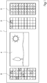
- Figure 1 shows an example of a printed sheet 7 with panel 11, in this case an image, and print control elements 8 arranged outside panel 11 - as is customary in the prior art. Which and how many print control elements 8 are placed on the sheet 7 depends on the benefit 11, the type of printing process and the type of quality control.
- the control elements 8 are recorded by cameras and the images generated are evaluated either internally in the control computer of the printing machine 11 or on an external server and the results are shown on a display.
- Such large and cost-intensive printing machines 11 are, however, particularly in the case of small printing houses, the surroundings of which are exemplary in Figure 5 is not available. For the smaller printing machines 11 used there, an alternative procedure is necessary for reasons of cost.
- a machine-readable data code 2 is placed under the identification code 3, which contains information 1 about the type of print control element 8, the position and size relative to the center of the machine-readable data code 2 as well as the machine number of the printing press, the job number (if known), the identification code 3 and contain the current date and time.
- Code 2 can consist, for example, of a QR code, a bar code or a data matrix code and must be readable using known OCR methods.
- Figure 2 and Figure 3 show two examples of the arrangement of identification code 3 and machine-readable data code 2 in addition to a print control element 8. It is also possible in an alternative embodiment variant that the machine-readable data code 2 is part of the print control element 8.
- the creation of the identification codes 3 and machine-readable data codes 2 for each print control element 8 is carried out as part of the creation of the prepress data of the print job.
- further print quality-relevant parameters of the printing process for example speed, temperature, humidity, paper / substrate type
- the control computer of the printing press 11 collects this information and modifies the machine-readable data code 2 by adding the collected information to it.
- a quality control is carried out during the processing of the print job at intervals determined by the user.
- the possible range extends from the implementation only in the case of visible quality defects in use to the inspection of each printed sheet 7.
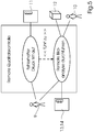
- the decision is up to the user 9. If he decides to carry out, he takes photos using a mobile communication device with camera function 13, for example a commercially available one Smartphones or tablet computers, the print control element 8 of the printed sheet 7 to be checked, or printed sheet cutout 4, and the associated machine-readable data code 2. The necessary position information can be found in the identification code 3. If the defects that have occurred are only present in benefit 4 of the printed product, the relevant point of use can also be photographed.
- the image 5 generated in this way is forwarded via the wireless communication interface of the smartphone 13 to a computer 12 in the support center.
- the control of the camera of the smartphone 13 and the forwarding of the generated image data 5 are carried out by an application program created for this purpose, which runs on the smartphone 13.
- This application program is configured by user 9 via a graphical user interface (GUI) with regard to the environmental parameters (IP address, target server, etc.). If the user data 4 are to be included in the analysis, the user 9 must do so also inform the application program. Depending on the version, the program also gives user 9 help with configuration and use via the GUI.
- the application program decodes the machine-readable data code 2 and links the information obtained in this way with the image data 5.
- the pre-analysis is configurable.
- the meaning of such a preliminary analysis also depends heavily on the computing power of the smartphone 13 used. If it is too weak, the time required for the preliminary analysis becomes too great, or the information gain that is possible in a reasonable time is too small. In particular in the event of an interruption in the data connection to the support computer 12, however, the preliminary analysis remains an important element in order to enable the user 9 to immediately assess the print quality.
- the image data 5 are temporarily stored in the memory of the smartphone 13 when the data connection is interrupted, and then sent to the computer 12 in the support center after the data connection has been restored.
- the image data 5 Once the image data 5 have reached the support center, they are analyzed with the aid of the information regarding printing errors obtained from the machine-readable data code 2.
- the analysis results 6, ie the printing errors found together with the possible cause, are then sent to the smartphone 13 via the still existing or to be re-established data connection. There they are made available to user 9 via the GUI of the application program. The latter then has the option of making the necessary corrections to the settings of the printing press 11.
Landscapes
- Engineering & Computer Science (AREA)
- Multimedia (AREA)
- Signal Processing (AREA)
- General Engineering & Computer Science (AREA)
- Theoretical Computer Science (AREA)
- Health & Medical Sciences (AREA)
- General Health & Medical Sciences (AREA)
- Biomedical Technology (AREA)
- Physics & Mathematics (AREA)
- General Physics & Mathematics (AREA)
- Human Computer Interaction (AREA)
- Computing Systems (AREA)
- Quality & Reliability (AREA)
- Computer Vision & Pattern Recognition (AREA)
- Accessory Devices And Overall Control Thereof (AREA)
Description
Die vorliegende Erfindung betrifft ein Verfahren und eine Vorrichtung zur Identifikation von Druckkontrollelementen für die Qualitätsdatenerfassung.The present invention relates to a method and a device for identifying pressure control elements for quality data acquisition.
Die Erfindung liegt in dem technischen Gebiet des Qualitätsmanagements.The invention lies in the technical field of quality management.
Der bisherige Stand der Technik umfasst zwei Hauptbereiche: Zum einen sind dies die bekannten Verfahren zur Durchführung einer Remote Qualitätskontrolle im Kundeneinsatz. Dabei ist es bisher üblich, dass die größeren Druckmaschinen über eine integrierte Qualitätskontrolle verfügen, so dass die mit ihnen hergestellten Druckprodukte im Betrieb automatisch auf die gewünschte Qualität hin kontrolliert werden. Dafür sind, vereinfacht formuliert, am Ende der Drucklinie eine oder mehrere Kameras angebracht, welche die hergestellten Druckprodukte einmalig als Bild oder fortlaufend aufnehmen. Die so erzeugten Bilder werden entweder lokal vom Steuerungsrechner der Druckmaschine ausgewertet, welcher über seine Anzeige- und Bedienelemente, wie z. B. einem Touchscreen oder einem Display, dem Benutzer die gefundenen Fehler anzeigt. Oder falls der Steuerungsrechner der Druckmaschine diese Aufgaben nicht übernehmen kann, werden die aufgenommenen Bilddaten über ein Netzwerk an einen externen Rechner weitergeleitet und die Auswertung geschieht dort. Der externe Rechner leitet dann die gefundenen Fehler über ein lokales oder über ein durch ein Netzwerk verbundenes externes Anzeigeelement an den Bediener der Druckmaschine weiter. Da diese integrierten Systeme einen erhöhten finanziellen Aufwand erfordern, werden sie üblicherweise nur bei großen und entsprechend teuren Druckmaschinen eingesetzt. Den zweiten Hauptbereich des Standes der Technik stellen daher die behelfsmäßigen Lösungen dar, auf welche bei kleineren und kostengünstigeren Systemen bisher zurückgegriffen wird. So ist es aus dem Stand der Technik bekannt, die Druckqualität solcher kleinerer Druckmaschinen durch den Einsatz von kleinen mobilen Messgeräten, wie z. B. Handdensitometern, vor Ort zu überprüfen. Dabei können mit diesen mobilen Geräten sowohl die Druckprodukte selbst, als auch die Kontrollelemente, wie z. B. Farbmessstreifen, untersucht werden. Eine weitere aus dem Stand der Technik bekannte Verfahrensweise besteht darin, gedruckte Druckkontrollelemente, bzw. Bildqualitätsfehler einzuscannen oder mittels einer Digitalkamera abzufotografieren und die so aufgenommenen Bilder dann per E-Mail an den zuständigen Supportservice weiterzuleiten. All diese Vorgehensweisen haben jedoch den Nachteil, dass die beschriebenen Untersuchungen von geschulten Servicemitarbeitern, z.B. des Druckmaschinenherstellers, durchgeführt werden müssen, da insbesondere in kleineren Druckereien beim dortigen Personal nicht das notwendige Fachwissen vorhanden ist, um die auszumessenden Prüfobjekte korrekt auszuwählen und zu untersuchen. Um diese Probleme zu lösen, bietet sich der Einsatz von handelsüblichen kamerafähigen Mobiltelefonen an, mit welchen die zu untersuchenden Messorte der Druckprodukte fotografiert und weitergeleitet werden können. Die Weiterleitung der Daten zum Supportcenter sollte dabei bevorzugt über die Datenschnittstelle des Mobiltelefons geschehen. Ein solches Verfahren ist auch von normalen Anwendern ohne größeres drucktechnisches Fachwissen durchführbar. Schwierigkeit bleibt jedoch auch hier, die Auswahl der zu untersuchenden Messorte, sowie die verfahrensgerechte Durchführung der Bildaufnahme, um vom Supportcenter verwertbare Kontrollaufnahmen zu erhalten. Ein weiteres Problem bei dieser Vorgehensweise ist, dass die so aufgenommen Bilder für eine schnelle und effiziente, d.h. automatische, Auswertung nur schwer systematisch einzuordnen sind. Denn neben allgemeinen Informationen über Zeit und Ort der Aufnahme sind zu einer automatisierten Auswertung auch Informationen über die Druckmaschine (z.B. anhand der Seriennummer), den Druckauftrag, die Art des Druckkontrollelements, die relative Position des Druckkontrollelements auf dem Bogen etc. erforderlich. Diese Informationen müssen vom Anwender dem aufgenommenen Bild hinzugefügt werden, was zum Einen zeitlichen Aufwand bedeutet und zum Anderen wiederum technisches Fachwissen erfordert, was dem eigentlichen Ziel eines einfachen, auch ohne größeres Fachwissen durchzuführenden, Verfahrens widerspricht.The current state of the art comprises two main areas: Firstly, these are the known methods for performing remote quality control in customer use. So far, it has been customary for the larger printing presses to have an integrated quality control so that the print products produced with them are automatically checked for the desired quality during operation. To put it simply, one or more cameras are attached to the end of the print line, which record the printed products once as a picture or continuously. The images generated in this way are either evaluated locally by the control computer of the printing press, which via its display and operating elements, such as, for. B. a touchscreen or a display, the user shows the errors found. Or if the control computer of the printing press cannot take over these tasks, the recorded image data are forwarded to an external computer via a network and the evaluation takes place there. The external computer then forwards the errors found to the operator of the printing press via a local display element or via an external display element connected by a network. Since these integrated systems require an increased financial outlay, they are usually only used in large and correspondingly expensive printing presses. The second main area of the prior art is therefore the makeshift solutions that have been used so far in smaller and less expensive systems. So it is known from the prior art, the print quality of such smaller printing presses through the use of small mobile measuring devices, such as. B. hand densitometers to check on site. With these mobile devices, both the printed products themselves and the Control elements such as B. color measuring strips to be examined. Another procedure known from the prior art is to scan printed print control elements or image quality errors or to photograph them using a digital camera and then to forward the images thus recorded to the responsible support service by email. However, all of these procedures have the disadvantage that the described examinations must be carried out by trained service employees, for example the printing press manufacturer, since, in particular in smaller printing plants, the personnel there does not have the necessary specialist knowledge to correctly select and examine the test objects to be measured. In order to solve these problems, the use of commercially available mobile phones with cameras is suitable, with which the measuring locations of the printed products to be examined can be photographed and forwarded. The data should preferably be forwarded to the support center via the data interface of the mobile phone. Such a method can also be carried out by normal users without extensive technical printing knowledge. However, the difficulty remains here, the selection of the measuring locations to be examined, as well as the procedural execution of the image acquisition in order to obtain usable control images from the support center. Another problem with this procedure is that the images recorded in this way are difficult to classify systematically for fast and efficient, ie automatic, evaluation. Because in addition to general information about the time and place of the recording, automated evaluation also requires information about the printing press (e.g. based on the serial number), the print job, the type of print control element, the relative position of the print control element on the sheet, etc. This information has to be added to the captured image by the user, which on the one hand means expenditure of time and on the other hand requires technical expertise, which contradicts the actual aim of a simple method that can also be carried out without any great expertise.
Die US-Patentanmeldung
Aus der US-Patentanmeldung
Das US-Patent
Die Aufgabe der vorliegenden Erfindung besteht somit darin, ein kostengünstiges Verfahren sowie eine Vorrichtung zur Durchführung einer Remote-Druckqualitätsanalyse zu beschreiben, welches von einem Anwender ohne drucktechnisches Fachwissen durchgeführt werden kann und in dem sämtliche zur Durchführung des Verfahrens notwendigen Informationen automatisch mit erfasst werden.The object of the present invention is therefore to describe a cost-effective method and a device for carrying out a remote print quality analysis which can be carried out by a user without technical printing knowledge and in which all the information necessary for carrying out the method is automatically recorded.
Die erfindungsgemäße Lösung dieser Aufgabe stellt ein Verfahren mit den Merkmalen von Hauptanspruch 1 dar. Es handelt sich dabei um ein Verfahren zur Identifikation von Druckkontrollelementen für die Qualitätsdatenerfassung.The solution to this problem according to the invention is a method with the features of main claim 1. It is a method for identifying print control elements for quality data acquisition.
Der maschinenlesbare Datencode kann dabei aus einem QR-Code, einem Barcode, einem Datamatrixcode oder ähnlichen Datencodes bestehen. Zudem muss er mittels aus dem Stand der Technik bekannter OCR-Verfahren verarbeitet werden können.The machine-readable data code can consist of a QR code, a bar code, a data matrix code or similar data codes. In addition, it must be able to be processed using OCR methods known from the prior art.
Vorteilhafte und daher bevorzugte Weiterbildungen des Verfahrens ergeben sich aus den zugehörigen Unteransprüchen.Advantageous and therefore preferred further developments of the method result from the associated subclaims.
Eine bevorzugte Weiterbildung des erfindungsgemäßen Verfahrens ist dabei, dass zusätzlich zum maschinenlesbaren Datencode (2), zum Identifikationscode (3) und zum Druckkontrollelement (8) auch der gedruckte Nutzen (4) und zum Identifikationscode (3) auch der Nutzen (4) mit in die Qualitätsdatenerfassung einbezogen wird. Dies macht insbesondere dann Sinn, wenn Qualitätsmängel nur im gedruckten Nutzen auftauchen und nicht auch im Druckkontrollelement.A preferred development of the method according to the invention is that in addition to the machine-readable data code (2), the identification code (3) and the print control element (8), the printed benefit (4) and the identification code (3) also include the benefit (4) quality data acquisition is included. This makes particular sense if quality defects only appear in the printed benefit and not also in the print control element.
Eine bevorzugte Weiterbildung des erfindungsgemäßen Verfahrens ist dabei, dass es sich bei der Kommunikationsschnittstelle des mobilen Kommunikationsmittels um eine drahtlose Datenübertragung, insbesondere nach einem Mobilfunkstandard, handelt. Durch Benutzung der, bei jedem heute handelsüblichen kamerafähigen Mobiltelefons, vorhandenen Datenschnittstellen, wie z. B. WLAN, Bluetooth oder UMTS/LTE, können die Bildaufnahmen zu einem vernetzten Rechner, welcher die Auswertung übernimmt, weitergeleitet werden. Dabei kann es sich insbesondere um einen Server im Supportcenter handeln. Die drahtlose Datenübertragung erleichtert zudem den Datenexport zum Supportrechner, da die fotografierten Bilddaten ohne Benutzung zusätzlicher Hardware weitergeleitet werden können.A preferred development of the method according to the invention is that the communication interface of the mobile communication means is a wireless data transmission, in particular according to a mobile radio standard. By using the existing data interfaces, such as for every commercially available camera-compatible mobile phone. B. WLAN, Bluetooth or UMTS / LTE, the images can be forwarded to a networked computer, which takes over the evaluation. In particular, this can be a server in the support center. Wireless data transmission also facilitates data export to the support computer, since the photographed image data can be forwarded without the use of additional hardware.
Eine bevorzugte Weiterbildung des erfindungsgemäßen Verfahrens ist dabei, dass bei einem Ausfall der Kommunikationsschnittstelle die Bilddaten auf dem Speicher des mobilen Kommunikationsmittels zwischengespeichert und zu einem späteren Zeitpunkt exportiert werden. Sollte die Verbindung zum die Bilder verarbeitenden Zielserver zum Zeitpunkt der Aufnahme nicht gewährleistet sein, so können die Bilder zwischengespeichert und zu einem späteren Zeitpunkt zum Zielserver weitergeleitet werden: d.h. sobald die Kommunikationsschnittstelle wieder eine Verbindung zum Zielserver ermöglicht.A preferred development of the method according to the invention is that if the communication interface fails, the image data are temporarily stored in the memory of the mobile communication means and are exported at a later time. If the connection to the target server processing the images is not guaranteed at the time of the recording, the images can be buffered and forwarded to the target server at a later time: as soon as the communication interface enables a connection to the target server again.
Eine bevorzugte Weiterbildung des erfindungsgemäßen Verfahrens ist dabei, dass die Funktionen der Bildaufnahme, Bildverarbeitung und des Datenexports des mobilen Kommunikationsmittels durch ein auf dem Kommunikationsmittel aktives Anwendungsprogramm mit grafischer Benutzeroberfläche gesteuert werden. Um dem Benutzer die Durchführung des Verfahrens zu vereinfachen, bietet es sich an, ein auf dem mobilen Kommunikationsmittel aktives Anwendungsprogramm zu benutzen, welches die Funktionen der Bildaufnahme und Verarbeitung sowie des Exports zum Zielserver nach vorheriger Konfiguration durch den Benutzer automatisch durchführt. Das Anwendungsprogramm kann dabei durch eine gezielt auf die Anforderungen angepasste grafische Benutzeroberfläche vom Benutzer bedient werden.A preferred development of the method according to the invention is that the functions of image acquisition, image processing and data export of the mobile communication means are controlled by an application program with a graphical user interface active on the communication means. In order to simplify the implementation of the method for the user, it is advisable to use an application program which is active on the mobile communication means and which automatically carries out the functions of image acquisition and processing and of export to the target server after the user has configured it beforehand. The application program can be operated by the user through a graphical user interface that is specifically adapted to the requirements.
Eine bevorzugte Weiterbildung des erfindungsgemäßen Verfahrens ist dabei, dass das auf dem mobilen Kommunikationsmittel aktive Anwendungsprogramm die aufgenommenen maschinenlesbaren Datencodes dekodiert, mittels der so gewonnenen Informationen eine Voranalyse der Bilddaten durchführt und das Ergebnis der Voranalyse über die Benutzeroberfläche anzeigt. Bei Verwendung des bereits beschriebenen Anwendungsprogrammes ist es sinnvoll, eine Voranalyse der erfassten Bilddaten vor der eigentlichen Analyse auf dem Zielserver durchführen zu lassen, um dem Benutzer bereits erste Informationen über die erhaltene Druckqualität zu geben. Dabei sollte keine vollständige Analyse der erzeugten Bilddaten durchgeführt werden, da dies mit großer Wahrscheinlichkeit die Rechenkapazitäten der zugrundeliegenden Hardware, also des mobilen Kommunikationsmittels, übersteigt. Einzelne Qualitätsmerkmale, welche vom Anwendungsprogramm mit verhältnismäßig wenig Aufwand ermittelt werden können, sollten jedoch Bestandteil dieser Voranalyse sein. Diese bietet sich insbesondere an, wenn eine Verbindung zum verarbeitenden Rechner oder Server zu diesem Zeitpunkt nicht möglich ist.A preferred development of the method according to the invention is that the application program active on the mobile communication means decodes the machine-readable data codes recorded, carries out a pre-analysis of the image data by means of the information thus obtained and displays the result of the pre-analysis via the user interface. When using the application program already described, it makes sense to have the acquired image data pre-analyzed on the target server before the actual analysis, in order to provide the user with first information about the print quality obtained. In this case, a complete analysis of the generated image data should not be carried out, since this is very likely to exceed the computing capacities of the underlying hardware, that is to say the mobile communication means. Individual quality features, which from Application programs can be determined with relatively little effort, but should be part of this preliminary analysis. This is particularly useful if a connection to the processing computer or server is not possible at this time.
Zur Durchführung des vorgestellten Verfahrens wird zudem eine Oberfläche mit einem Code zur Identifikation von Druckkontrollelementen offenbart. Sie besteht aus einem von Menschen lesbaren Identifikationscode und einem maschinenlesbaren Datencode. Der Identifikationscode beinhaltet spezifische Angaben zur Position des Druckkontrollelementes auf dem Drucksubstrat, der maschinenlesbare Datencode dagegen sowohl spezifische Druckauftragsinformationen, als auch den Identifikationscode selbst. Beide Codes sind auf dem Drucksubstrat neben das Druckkontrollelement platziert, dessen spezifische Informationen sie beinhalten. Sie können aber auch gleichzeitig Bestandteil des Druckkontrollelementes sein.To carry out the method presented, a surface with a code for identifying pressure control elements is also disclosed. It consists of a human-readable identification code and a machine-readable data code. The identification code contains specific information on the position of the print control element on the print substrate, the machine-readable data code, on the other hand, contains both specific print job information and the identification code itself. Both codes are placed on the print substrate next to the print control element, the specific information of which they contain. But you can also be part of the pressure control element at the same time.
Eine bevorzugte Weiterbildung der erfindungsgemäßen Oberfläche mit einem Code ist dabei, dass der Identifikationscode aus 4 Teilen besteht, welche die relative Position und die Seite des Drucksubstrats, eine Angabe zur Position des Druckkontrollelements auf dem Drucksubstrat in einer Zone quer zur Druckrichtung, eine Angabe zur Position des Druckkontrollelements auf dem Drucksubstrat in einer Reihenfolge vom Druckanfang entlang der Druckrichtung, sowie die Art eines zu verwendenden Messgeräts enthalten. Mit diesen Angaben ist es dem Anwender möglich, das korrekte Druckkontrollelement für die Bildaufnahme der Qualitätskontrolle auszuwählen.A preferred further development of the surface according to the invention with a code is that the identification code consists of 4 parts, the relative position and the side of the printing substrate, an indication of the position of the printing control element on the printing substrate in a zone transverse to the printing direction, an indication of the position of the pressure control element on the printing substrate in an order from the start of printing along the printing direction, as well as the type of a measuring device to be used. With this information, it is possible for the user to select the correct print control element for the image recording of the quality control.
Eine bevorzugte Weiterbildung der erfindungsgemäßen Oberfläche mit einem Code ist dabei, dass der maschinenlesbare Datencode die Art des Druckkontrollelementes, die relative Position und Größe zum Mittelpunkt des Druckkontrollelementes, die Maschinennummer der Druckmaschine, die Auftragsnummer, den Identifikationscode, sowie aktuelles Datum und Uhrzeit beinhalten.
Diese Informationen werden für die automatisierte Auswertung der Bilddaten im Supportrechner benötigt. Da der maschinenlesbare Datencode Bestandteil der fotografierten Bilddaten ist, wird somit die Weiterleitung der Informationen an den Supportrechner gewährleistet.A preferred development of the surface according to the invention with a code is that the machine-readable data code contains the type of print control element, the relative position and size to the center of the print control element, the machine number of the printing press, the job number, the identification code and the current date and time.
This information is required for the automated evaluation of the image data in the support computer. Since the machine-readable data code is part of the photographed image data, the forwarding of the information to the support computer is guaranteed.
Eine bevorzugte Weiterbildung der erfindungsgemäßen Oberfläche mit einem Code ist dabei, dass der maschinenlesbare Datencode die druckqualitätsrelevanten Parameter der Geschwindigkeit, Temperatur, Feuchtigkeit, sowie des Papier-/Substrattyps beinhaltet. Die Einbeziehung dieser Informationen verbessert die mögliche Fehlererkennung in der automatischen Auswertung durch den Supportrechner. Anders als die in der vorherigen Weiterbildung beschriebenen, auftragsbezogenen Informationen sind diese druckbezogenen Informationen direkt vom Druckprozess abhängig und müssen daher von der Druckmaschine on-the-fly hinzugefügt werden. Da dies eine Erweiterung des maschinenlesbaren Datencodes während des Drucks erfordert, ist dieses Vorgehen hauptsächlich für Digitaldruckmaschinen geeignet.A preferred further development of the surface according to the invention with a code is that the machine-readable data code contains the print quality-relevant parameters of speed, temperature, humidity, and of the paper / substrate type. The inclusion of this information improves the possible detection of errors in the automatic evaluation by the support computer. Unlike the job-related information described in the previous development, this print-related information is directly dependent on the printing process and must therefore be added on-the-fly by the printing press. Since this requires an expansion of the machine-readable data code during printing, this procedure is mainly suitable for digital printing machines.
Das Verfahren sowie funktionell vorteilhafte Weiterbildungen des Verfahrens werden nachfolgend unter Bezug auf die zugehörigen Zeichnungen anhand wenigstens eines bevorzugten Ausführungsbeispiels näher beschrieben. In den Zeichnungen sind einander entsprechende Elemente mit jeweils denselben Bezugszeichen versehen.The method and functionally advantageous developments of the method are described in more detail below with reference to the associated drawings using at least one preferred exemplary embodiment. Corresponding elements are provided with the same reference symbols in the drawings.
Die Zeichnungen zeigen:
- Fig. 1:
- einen Druckbogen mit Druckkontrollelementen aus dem Stand der Technik
- Fig. 2:
- ein erstes Beispiel für Druckkontrollelemente mit zugehörigem Ident- und maschinenlesbaren Datencode
- Fig. 3:
- ein zweites Beispiel für Druckkontrollelemente mit zugehörigem Ident- und maschinenlesbaren Datencode
- Fig. 4:
- einen bevorzugten Ablauf des Verfahrens zur Qualitätsdatenerfassung mit identifizierten Druckkontrollelementen
- Fig. 5:
- einen Anwendungsfall für die Durchführung einer Remote Qualitätskontrolle
- Fig. 1:
- a printed sheet with pressure control elements from the prior art
- Fig. 2:
- a first example of print control elements with associated identification and machine-readable data code
- Fig. 3:
- a second example of print control elements with associated identification and machine-readable data code
- Fig. 4:
- a preferred sequence of the method for quality data acquisition with identified print control elements
- Fig. 5:
- a use case for performing a remote quality control
Im bevorzugten Ausführungsbeispiel, dessen Ablauf schematisch in
- a) die Seite, d.h. die relative Nummer des Bogens 7 + Angabe zur Vorder- oder Rückseite ("F"=Front, "B"=Back)
- b) einer zonalen Y-Angabe, quer zur Druckrichtung ausgehend vom unteren Bogenrand
- c) einer alphanumerischen X-Angabe, d.h. die relative Nummer des
Druckkontrollelements 8 auf dem Bogen 7 vom Druckanfang entlang der Druckrichtung - d) einer Angabe, welche Art des Messgerätes (Microscope Camera ("M") oder Densitometer "D") verwendet werden soll.
- a) the side, ie the relative number of the sheet 7 + information on the front or back ("F" = front, "B" = back)
- b) a zonal Y specification, starting from the lower sheet edge, transverse to the printing direction
- c) an alphanumeric X specification, ie the relative number of the
print control element 8 on the sheet 7 from the start of printing along the printing direction - d) an indication of what type of measuring device (microscope camera ("M") or densitometer "D") is to be used.
Beispiel: 3B:4:F-M beschreibt das Druckkontrollelement 8 auf der Rückseite des 3. Bogens 7 in der Zone 4, Element 6, welches mit einer Kamera zu erfassen ist.Example: 3B: 4: FM describes the
Unter dem Identifizierungscode 3 wird ein maschinenlesbarer Datencode 2 platziert, welcher Informationen 1 über die Art des Druckkontrollelements 8, die relative Position und Größe zum Mittelpunkt des maschinenlesbaren Datencodes 2 sowie die Maschinennummer der Druckmaschine, die Auftragsnummer (sofern bekannt), den Identifizierungscode 3, sowie das aktuelle Datum und die Uhrzeit enthalten. Der Code 2 kann z.B. aus einem QR-Code, einem Barcode oder einem Datamatrixcode bestehen und muss mittels bekannter OCR-Verfahren auslesbar sein.
Die Erstellung der Identifizierungscodes 3- und der maschinenlesbaren Datencodes 2 für jedes Druckkontrollelement 8 wird im Rahmen der Erstellung der Vorstufendaten des Druckauftrages durchgeführt.
In einem weiteren bevorzugten Ausführungsbeispiel werden zudem bei Verwendung einer Digitaldruckmaschine 11 weitere druckqualitätsrelevante Parameter des Druckvorgangs (z.B. Geschwindigkeit, Temperatur, Feuchtigkeit, Papier-/Substrattyp) dem maschinenlesbaren Datencode 2 hinzugefügt. Da die meisten dieser Parameter nur kurzfristig verfügbar sind, muss dies on-the-fly geschehen. Dazu sammelt der Steuerungsrechner der Druckmaschine 11 diese Informationen und modifiziert den maschinenlesbaren Datencode 2 indem er die gesammelten Informationen diesem hinzufügt.The creation of the
In a further preferred exemplary embodiment, when using a
Im zweiten Schritt des erfindungsgemäßen Verfahrens wird während der Bearbeitung des Druckauftrages in, vom Anwender festgelegten Abständen, eine Qualitätskontrolle durchgeführt. Die mögliche Spanne reicht dabei von der Durchführung nur bei sichtbaren Qualitätsmängeln im Nutzen bis hin zur Kontrolle jedes Druckbogens 7. Die Entscheidung darüber liegt beim Anwender 9. Entscheidet er sich zur Durchführung so fotografiert er mittels eines mobilen Kommunikationsmittels mit Kamerafunktion 13, also z.B. eines handelsüblichen Smartphones oder Tablet-Computers, das Druckkontrollelement 8 des zu prüfenden Druckbogens 7, bzw. Druckbogenausschnittes 4, sowie den zugehörigen maschinenlesbaren Datencode 2. Die notwendigen Positionsangaben sind dem Identifizierungscode 3 zu entnehmen. Falls die aufgetretenen Mängel nur im Nutzen 4 des Druckproduktes vorhanden sind, kann auch die betreffende Stelle des Nutzens mit fotografiert werden. Das so erzeugte Bild 5 wird über die drahtlose Kommunikationsschnittstelle des Smartphones 13 an einen Rechner 12 im Supportcenter weitergeleitet. Die Steuerung der Kamera des Smartphones 13, sowie die Weiterleitung der erzeugten Bilddaten 5 werden dabei von einem für diesen Zweck erstellten Anwendungsprogramm, welches auf dem Smartphone 13 läuft, übernommen. Dieses Anwendungsprogramm wird vom Nutzer 9 über eine grafische Benutzeroberfläche (GUI) hinsichtlich der Umgebungsparameter (IP-Adresse, Zielserver, etc.) konfiguriert. Falls die Nutzdaten 4 mit in die Analyse miteinbezogen werden sollen, muss der Anwender 9 dies ebenfalls dem Anwendungsprogramm mitteilen. Das Programm gibt zudem, je nach Ausführung, dem Nutzer 9 über die GUI Hilfestellung bei Konfiguration und Anwendung. Als Nächstes dekodiert das Anwendungsprogramm den maschinenlesbaren Datencode 2 und verknüpft die so gewonnen Informationen mit den Bilddaten 5. Je nach Konfiguration ist es zudem in der Lage eine Voranalyse hinsichtlich der Druckqualität der aufgenommenen Bilddaten 5 durchzuführen und die Ergebnisse dem Nutzer 9 zusammen mit den Informationen des maschinenlesbaren Datencodes 2 über die GUI anzuzeigen. Der Umfang der Voranalyse hinsichtlich welche Daten analysiert werden sollen, ist dabei konfigurierbar. Der Sinn einer solchen Voranalyse hängt zudem stark von der Rechenleistung des benutzten Smartphones 13 ab. Ist sie zu schwach, wird der Zeitaufwand für die Voranalyse zu groß, bzw. der Informationsgewinn, welcher in einer vertretbaren Zeit möglich ist, zu gering. Insbesondere für den Fall einer Unterbrechung der Datenverbindung zum Supportrechner 12 bleibt die Voranalyse jedoch ein wichtiges Element, um dem Nutzer 9 sofort eine Einschätzung der Druckqualität zu ermöglichen. Zudem werden die Bilddaten 5 bei einer Unterbrechung der Datenverbindung auf dem Speicher des Smartphones 13 zwischengespeichert, und dann nach Wiederherstellung der Datenverbindung zum Rechner 12 im Supportcenter gesendet. Sind die Bilddaten 5 im Supportcenter angekommen werden sie unter Mithilfe der aus dem maschinenlesbaren Datencode 2 gewonnen Informationen bzgl. Druckfehler analysiert. Die Analyseergebnisse 6, d.h. die gefundenen Druckfehler samt möglicher Ursache, werden dann über die noch bestehende oder wieder aufzubauende Datenverbindung zum Smartphone 13 gesendet. Dort werden sie über die GUI des Anwendungsprogrammes den Nutzer 9 zur Verfügung gestellt. Dieser hat dann die Möglichkeit, die notwendigen Korrekturen an den Einstellungen der Druckmaschine 11 vorzunehmen.In the second step of the method according to the invention, a quality control is carried out during the processing of the print job at intervals determined by the user. The possible range extends from the implementation only in the case of visible quality defects in use to the inspection of each printed sheet 7. The decision is up to the
- 11
- DruckauftragsinformationenPrint job information
- 22nd
- maschinenlesbarer Datencode für jedes Kontrollelementmachine-readable data code for each control element
- 33rd
- Ident-Code für jedes KontrollelementIdent code for each control element
- 44th
- gedrucktes Bild (Nutzen)printed image (benefit)
- 55
- fotografierte Bilddatenphotographed image data
- 66
- AnalyseergebnisseAnalysis results
- 77
- DruckbogenPrinted sheet
- 88th
- DruckkontrollelementPressure control element
- 99
- Drucker (Anwender)Printer (user)
- 1010th
- Support-MitarbeiterSupport staff
- 1111
- DruckmaschinePrinting press
- 1212th
- Support-RechnerSupport calculator
- 1313
- mobiles Kommunikationsmittel mit Kameramobile means of communication with camera
- 1414
- Smartphone-AdapterSmartphone adapter
Claims (6)
- Method for identifying print control elements (8) in the form of colour measurement strips for obtaining data on quality, comprising the following steps of• encoding specific information on the position of the print control element (8) as text in a four-part identification code (3), said specific information in the form of a relative position and a side of the printing substrate, information on the position of the print control element (8) on the printing substrate in a zone transverse to the printing direction and information on the position of the print control element (8) on the printing substrate in an order from the print start along the printing direction as well as the type of measurement device to be used• encoding specific print job information (1) and the identification code (3) as a bar code into a data code (2)• positioning the data code (2) and the identification code (3) next to the associated print control elements (8) thereof on the printing substrate• photographing the printed print control element (8) and the adjacent machine-readable data code (2) by means of the information of the adjacent identification code (3) in that a machine operator (9) obtains information on how to photograph the control element (8) from the identification code (3), and processing the data using a mobile communication device (13) that has a camera function and a communication interface• exporting the generated image data (5) to a support computer (12) via the communication interface of the mobile communication device (13)• decoding the machine-readable data code (2)• analysing the image data (5) on the support computer (12) by means of the information obtained from the decoded machine-readable data code (2)• forwarding the results (6) of the analysis from the support computer (12) to the mobile communication device (13) and presenting the results (6) of the analysis via the graphical user interface of the mobile communication device (13)• correcting the faulty settings found as a result of the analysis of the image on the printing machine (11) that produces the printed products in that the machine operator (9) makes corrections
- Method according to claim 1,
wherein along with the data code (2), identification code (3) and print control element (8), the printed copy (4) of the image is factored into the process of obtaining data on quality. - Method according to claim 1 or claim 2,
wherein the communication interface of the mobile communication device (13) is wireless data transfer, in particular a mobile telecommunications standard. - Method according to any one of the preceding claims,
wherein in the case of a failure of the communication interface, the image data (5) are buffered in the memory of the mobile communication device (13) and exported at a later time. - Method according to any one of the preceding claims,
wherein the functions of the mobile communication device (13) of recording the image, processing the image and exporting the data are controlled by an application programme active on the mobile communication device (13) and having a graphical user interface. - Method according to claim 5,
wherein the application programme (13) active on the mobile communication device (13) decodes the recorded data codes (2), uses the information obtained in this way to pre-analyze the image data and displays the pre-analysis result on the graphical user interface.
Applications Claiming Priority (1)
| Application Number | Priority Date | Filing Date | Title |
|---|---|---|---|
| DE102014210690.7A DE102014210690A1 (en) | 2014-06-05 | 2014-06-05 | Method for identifying print control elements for quality data acquisition |
Publications (2)
| Publication Number | Publication Date |
|---|---|
| EP2953019A1 EP2953019A1 (en) | 2015-12-09 |
| EP2953019B1 true EP2953019B1 (en) | 2020-04-22 |
Family
ID=53483649
Family Applications (1)
| Application Number | Title | Priority Date | Filing Date |
|---|---|---|---|
| EP15167282.1A Active EP2953019B1 (en) | 2014-06-05 | 2015-05-12 | Method for identification of print control elements for quality data acquisition |
Country Status (4)
| Country | Link |
|---|---|
| US (1) | US9848093B2 (en) |
| EP (1) | EP2953019B1 (en) |
| CN (1) | CN105278888B (en) |
| DE (1) | DE102014210690A1 (en) |
Families Citing this family (7)
| Publication number | Priority date | Publication date | Assignee | Title |
|---|---|---|---|---|
| DE102015111348A1 (en) * | 2015-07-14 | 2017-01-19 | Manroland Web Systems Gmbh | Method for controlling or regulating a production process in printing plants |
| DE102015216264A1 (en) * | 2015-08-26 | 2017-03-02 | Koenig & Bauer Ag | Pressure gauges and methods of application |
| DE102019211687A1 (en) * | 2018-09-11 | 2020-03-12 | Heidelberger Druckmaschinen Ag | Meta information coding for inkjet printing processes |
| DE102018220236A1 (en) * | 2018-11-26 | 2020-05-28 | Heidelberger Druckmaschinen Ag | Fast image rectification for image inspection |
| US10929073B2 (en) * | 2019-03-15 | 2021-02-23 | Ricoh Company, Ltd. | Information processing system |
| US20220028053A1 (en) * | 2019-03-19 | 2022-01-27 | Hewlett-Packard Development Company, L.P. | Extraction and comparison of actual and target surface attribute values |
| CN113436196B (en) * | 2021-08-27 | 2021-12-10 | 广州市雄星塑料制品有限公司 | Two-dimensional code film production management system based on image recognition technology |
Family Cites Families (8)
| Publication number | Priority date | Publication date | Assignee | Title |
|---|---|---|---|---|
| EP0149424B1 (en) * | 1983-12-19 | 1990-11-14 | GRETAG Aktiengesellschaft | Method and device for determining the quality of prints, and colour test strip for said determination |
| US7728845B2 (en) * | 1996-02-26 | 2010-06-01 | Rah Color Technologies Llc | Color calibration of color image rendering devices |
| DE102006050409A1 (en) | 2006-06-02 | 2007-12-06 | Gavitec Ag | System and method for image and data upload with mobile terminal |
| US8054501B2 (en) * | 2007-11-07 | 2011-11-08 | Final Print Assurance Inc. | System and method for analyzing print quality |
| US8902454B2 (en) * | 2009-10-14 | 2014-12-02 | Ricoh Co., Ltd. | Methods for printing from mobile devices |
| JP5635917B2 (en) * | 2011-01-19 | 2014-12-03 | 株式会社キーエンス | Print quality evaluation system, laser marking device, print condition setting device, print quality evaluation device, print condition setting program, print quality evaluation program, computer-readable recording medium |
| US20120194874A1 (en) * | 2011-02-01 | 2012-08-02 | Milanski John G | Mobile Print Quality Assurance Mechanism |
| US8988716B1 (en) * | 2012-02-17 | 2015-03-24 | Google Inc. | Customized printer identifier with embedded access rights |
-
2014
- 2014-06-05 DE DE102014210690.7A patent/DE102014210690A1/en not_active Withdrawn
-
2015
- 2015-05-12 EP EP15167282.1A patent/EP2953019B1/en active Active
- 2015-06-01 CN CN201510292440.3A patent/CN105278888B/en active Active
- 2015-06-05 US US14/731,640 patent/US9848093B2/en active Active
Non-Patent Citations (1)
| Title |
|---|
| None * |
Also Published As
| Publication number | Publication date |
|---|---|
| CN105278888B (en) | 2019-12-03 |
| US9848093B2 (en) | 2017-12-19 |
| EP2953019A1 (en) | 2015-12-09 |
| US20150358488A1 (en) | 2015-12-10 |
| DE102014210690A1 (en) | 2015-12-17 |
| CN105278888A (en) | 2016-01-27 |
Similar Documents
| Publication | Publication Date | Title |
|---|---|---|
| EP2953019B1 (en) | Method for identification of print control elements for quality data acquisition | |
| EP2052807B1 (en) | Assembly workstation | |
| DE10034606B4 (en) | Method for providing manufacturing-related data in a series production of manufacturing objects, in particular motor vehicles | |
| DE102016224307A1 (en) | Method of checking an image inspection system | |
| EP2849142B1 (en) | Smartphone-assisted maintenance of a self-service terminal | |
| EP3768902A1 (en) | Method and device for maintaining and/or repairing a construction machine | |
| DE102011083817A1 (en) | Method for establishing wireless connection of e.g. smartphone with wireless local area network-capable machine tool, involves displaying access data to radio network of tool, and optically detecting access data by communication apparatus | |
| WO2016188611A1 (en) | Method for producing spare parts for packaging machines | |
| EP2960058B1 (en) | Method and device for controlling and regulating a digital printing process | |
| EP3296051A2 (en) | Method of controlling a welding device, system comprising a welding device and computer program | |
| DE102016204506A1 (en) | Production pressure inspection with local optimization | |
| WO2011120624A1 (en) | Mobile maintenance unit | |
| EP2700505B1 (en) | Method for testing the printed product of rotation printers | |
| EP2764371B1 (en) | Maintenance arrangement for an analysis device | |
| EP0763427B2 (en) | Method for controlling the production of images on a printing plate carrier for a printing machine | |
| DE102009007864A1 (en) | Method for color measuring of print substrate, involves carrying out color analysis of print image applied on print substrate by computer with test element, where areas of print image are determined on basis of analyzed data by computer | |
| DE112019005903T5 (en) | SYSTEM FOR TEST AND MEASURING INSTRUMENTATION DATA COLLECTION AND EXCHANGE | |
| EP0909647B1 (en) | Control console for a printing machine | |
| WO2014177309A1 (en) | Information system and method for processing information, in particular for assisting work in a motor vehicle repair shop | |
| DE102015208381A1 (en) | Procedure for performing a remote quality control of printed matter | |
| WO2020016123A1 (en) | Laboratory management system | |
| EP3104299B1 (en) | Creation of marks in the preliminary stage of a printing process | |
| EP2711885B1 (en) | Process device with conversion equipment | |
| DE102018118510B4 (en) | Laboratory device, laboratory device system and method for data transmission | |
| DE112020007830T5 (en) | Device management system |
Legal Events
| Date | Code | Title | Description |
|---|---|---|---|
| PUAI | Public reference made under article 153(3) epc to a published international application that has entered the european phase |
Free format text: ORIGINAL CODE: 0009012 |
|
| AK | Designated contracting states |
Kind code of ref document: A1 Designated state(s): AL AT BE BG CH CY CZ DE DK EE ES FI FR GB GR HR HU IE IS IT LI LT LU LV MC MK MT NL NO PL PT RO RS SE SI SK SM TR |
|
| AX | Request for extension of the european patent |
Extension state: BA ME |
|
| 17P | Request for examination filed |
Effective date: 20160609 |
|
| RBV | Designated contracting states (corrected) |
Designated state(s): AL AT BE BG CH CY CZ DE DK EE ES FI FR GB GR HR HU IE IS IT LI LT LU LV MC MK MT NL NO PL PT RO RS SE SI SK SM TR |
|
| STAA | Information on the status of an ep patent application or granted ep patent |
Free format text: STATUS: EXAMINATION IS IN PROGRESS |
|
| 17Q | First examination report despatched |
Effective date: 20181004 |
|
| RAP1 | Party data changed (applicant data changed or rights of an application transferred) |
Owner name: HEIDELBERGER DRUCKMASCHINEN AG |
|
| RIC1 | Information provided on ipc code assigned before grant |
Ipc: G06F 3/12 20060101AFI20191205BHEP Ipc: H04N 1/00 20060101ALI20191205BHEP Ipc: G06K 15/02 20060101ALI20191205BHEP Ipc: H04N 1/32 20060101ALI20191205BHEP |
|
| GRAP | Despatch of communication of intention to grant a patent |
Free format text: ORIGINAL CODE: EPIDOSNIGR1 |
|
| STAA | Information on the status of an ep patent application or granted ep patent |
Free format text: STATUS: GRANT OF PATENT IS INTENDED |
|
| INTG | Intention to grant announced |
Effective date: 20200117 |
|
| GRAS | Grant fee paid |
Free format text: ORIGINAL CODE: EPIDOSNIGR3 |
|
| GRAA | (expected) grant |
Free format text: ORIGINAL CODE: 0009210 |
|
| STAA | Information on the status of an ep patent application or granted ep patent |
Free format text: STATUS: THE PATENT HAS BEEN GRANTED |
|
| AK | Designated contracting states |
Kind code of ref document: B1 Designated state(s): AL AT BE BG CH CY CZ DE DK EE ES FI FR GB GR HR HU IE IS IT LI LT LU LV MC MK MT NL NO PL PT RO RS SE SI SK SM TR |
|
| REG | Reference to a national code |
Ref country code: CH Ref legal event code: EP |
|
| REG | Reference to a national code |
Ref country code: DE Ref legal event code: R096 Ref document number: 502015012333 Country of ref document: DE |
|
| REG | Reference to a national code |
Ref country code: IE Ref legal event code: FG4D Free format text: LANGUAGE OF EP DOCUMENT: GERMAN |
|
| REG | Reference to a national code |
Ref country code: AT Ref legal event code: REF Ref document number: 1261003 Country of ref document: AT Kind code of ref document: T Effective date: 20200515 |
|
| REG | Reference to a national code |
Ref country code: LT Ref legal event code: MG4D |
|
| REG | Reference to a national code |
Ref country code: NL Ref legal event code: MP Effective date: 20200422 |
|
| PG25 | Lapsed in a contracting state [announced via postgrant information from national office to epo] |
Ref country code: SE Free format text: LAPSE BECAUSE OF FAILURE TO SUBMIT A TRANSLATION OF THE DESCRIPTION OR TO PAY THE FEE WITHIN THE PRESCRIBED TIME-LIMIT Effective date: 20200422 Ref country code: IS Free format text: LAPSE BECAUSE OF FAILURE TO SUBMIT A TRANSLATION OF THE DESCRIPTION OR TO PAY THE FEE WITHIN THE PRESCRIBED TIME-LIMIT Effective date: 20200822 Ref country code: FI Free format text: LAPSE BECAUSE OF FAILURE TO SUBMIT A TRANSLATION OF THE DESCRIPTION OR TO PAY THE FEE WITHIN THE PRESCRIBED TIME-LIMIT Effective date: 20200422 Ref country code: PT Free format text: LAPSE BECAUSE OF FAILURE TO SUBMIT A TRANSLATION OF THE DESCRIPTION OR TO PAY THE FEE WITHIN THE PRESCRIBED TIME-LIMIT Effective date: 20200824 Ref country code: LT Free format text: LAPSE BECAUSE OF FAILURE TO SUBMIT A TRANSLATION OF THE DESCRIPTION OR TO PAY THE FEE WITHIN THE PRESCRIBED TIME-LIMIT Effective date: 20200422 Ref country code: NO Free format text: LAPSE BECAUSE OF FAILURE TO SUBMIT A TRANSLATION OF THE DESCRIPTION OR TO PAY THE FEE WITHIN THE PRESCRIBED TIME-LIMIT Effective date: 20200722 Ref country code: GR Free format text: LAPSE BECAUSE OF FAILURE TO SUBMIT A TRANSLATION OF THE DESCRIPTION OR TO PAY THE FEE WITHIN THE PRESCRIBED TIME-LIMIT Effective date: 20200723 Ref country code: NL Free format text: LAPSE BECAUSE OF FAILURE TO SUBMIT A TRANSLATION OF THE DESCRIPTION OR TO PAY THE FEE WITHIN THE PRESCRIBED TIME-LIMIT Effective date: 20200422 |
|
| PG25 | Lapsed in a contracting state [announced via postgrant information from national office to epo] |
Ref country code: BG Free format text: LAPSE BECAUSE OF FAILURE TO SUBMIT A TRANSLATION OF THE DESCRIPTION OR TO PAY THE FEE WITHIN THE PRESCRIBED TIME-LIMIT Effective date: 20200722 Ref country code: LV Free format text: LAPSE BECAUSE OF FAILURE TO SUBMIT A TRANSLATION OF THE DESCRIPTION OR TO PAY THE FEE WITHIN THE PRESCRIBED TIME-LIMIT Effective date: 20200422 Ref country code: RS Free format text: LAPSE BECAUSE OF FAILURE TO SUBMIT A TRANSLATION OF THE DESCRIPTION OR TO PAY THE FEE WITHIN THE PRESCRIBED TIME-LIMIT Effective date: 20200422 Ref country code: HR Free format text: LAPSE BECAUSE OF FAILURE TO SUBMIT A TRANSLATION OF THE DESCRIPTION OR TO PAY THE FEE WITHIN THE PRESCRIBED TIME-LIMIT Effective date: 20200422 |
|
| PG25 | Lapsed in a contracting state [announced via postgrant information from national office to epo] |
Ref country code: AL Free format text: LAPSE BECAUSE OF FAILURE TO SUBMIT A TRANSLATION OF THE DESCRIPTION OR TO PAY THE FEE WITHIN THE PRESCRIBED TIME-LIMIT Effective date: 20200422 |
|
| REG | Reference to a national code |
Ref country code: DE Ref legal event code: R097 Ref document number: 502015012333 Country of ref document: DE |
|
| PG25 | Lapsed in a contracting state [announced via postgrant information from national office to epo] |
Ref country code: SM Free format text: LAPSE BECAUSE OF FAILURE TO SUBMIT A TRANSLATION OF THE DESCRIPTION OR TO PAY THE FEE WITHIN THE PRESCRIBED TIME-LIMIT Effective date: 20200422 Ref country code: LI Free format text: LAPSE BECAUSE OF NON-PAYMENT OF DUE FEES Effective date: 20200531 Ref country code: EE Free format text: LAPSE BECAUSE OF FAILURE TO SUBMIT A TRANSLATION OF THE DESCRIPTION OR TO PAY THE FEE WITHIN THE PRESCRIBED TIME-LIMIT Effective date: 20200422 Ref country code: IT Free format text: LAPSE BECAUSE OF FAILURE TO SUBMIT A TRANSLATION OF THE DESCRIPTION OR TO PAY THE FEE WITHIN THE PRESCRIBED TIME-LIMIT Effective date: 20200422 Ref country code: CH Free format text: LAPSE BECAUSE OF NON-PAYMENT OF DUE FEES Effective date: 20200531 Ref country code: DK Free format text: LAPSE BECAUSE OF FAILURE TO SUBMIT A TRANSLATION OF THE DESCRIPTION OR TO PAY THE FEE WITHIN THE PRESCRIBED TIME-LIMIT Effective date: 20200422 Ref country code: MC Free format text: LAPSE BECAUSE OF FAILURE TO SUBMIT A TRANSLATION OF THE DESCRIPTION OR TO PAY THE FEE WITHIN THE PRESCRIBED TIME-LIMIT Effective date: 20200422 Ref country code: RO Free format text: LAPSE BECAUSE OF FAILURE TO SUBMIT A TRANSLATION OF THE DESCRIPTION OR TO PAY THE FEE WITHIN THE PRESCRIBED TIME-LIMIT Effective date: 20200422 Ref country code: ES Free format text: LAPSE BECAUSE OF FAILURE TO SUBMIT A TRANSLATION OF THE DESCRIPTION OR TO PAY THE FEE WITHIN THE PRESCRIBED TIME-LIMIT Effective date: 20200422 Ref country code: CZ Free format text: LAPSE BECAUSE OF FAILURE TO SUBMIT A TRANSLATION OF THE DESCRIPTION OR TO PAY THE FEE WITHIN THE PRESCRIBED TIME-LIMIT Effective date: 20200422 |
|
| PG25 | Lapsed in a contracting state [announced via postgrant information from national office to epo] |
Ref country code: PL Free format text: LAPSE BECAUSE OF FAILURE TO SUBMIT A TRANSLATION OF THE DESCRIPTION OR TO PAY THE FEE WITHIN THE PRESCRIBED TIME-LIMIT Effective date: 20200422 Ref country code: SK Free format text: LAPSE BECAUSE OF FAILURE TO SUBMIT A TRANSLATION OF THE DESCRIPTION OR TO PAY THE FEE WITHIN THE PRESCRIBED TIME-LIMIT Effective date: 20200422 |
|
| PLBE | No opposition filed within time limit |
Free format text: ORIGINAL CODE: 0009261 |
|
| STAA | Information on the status of an ep patent application or granted ep patent |
Free format text: STATUS: NO OPPOSITION FILED WITHIN TIME LIMIT |
|
| REG | Reference to a national code |
Ref country code: BE Ref legal event code: MM Effective date: 20200531 |
|
| 26N | No opposition filed |
Effective date: 20210125 |
|
| GBPC | Gb: european patent ceased through non-payment of renewal fee |
Effective date: 20200722 |
|
| PG25 | Lapsed in a contracting state [announced via postgrant information from national office to epo] |
Ref country code: LU Free format text: LAPSE BECAUSE OF NON-PAYMENT OF DUE FEES Effective date: 20200512 |
|
| PG25 | Lapsed in a contracting state [announced via postgrant information from national office to epo] |
Ref country code: GB Free format text: LAPSE BECAUSE OF NON-PAYMENT OF DUE FEES Effective date: 20200722 Ref country code: IE Free format text: LAPSE BECAUSE OF NON-PAYMENT OF DUE FEES Effective date: 20200512 Ref country code: FR Free format text: LAPSE BECAUSE OF NON-PAYMENT OF DUE FEES Effective date: 20200622 |
|
| PG25 | Lapsed in a contracting state [announced via postgrant information from national office to epo] |
Ref country code: BE Free format text: LAPSE BECAUSE OF NON-PAYMENT OF DUE FEES Effective date: 20200531 Ref country code: SI Free format text: LAPSE BECAUSE OF FAILURE TO SUBMIT A TRANSLATION OF THE DESCRIPTION OR TO PAY THE FEE WITHIN THE PRESCRIBED TIME-LIMIT Effective date: 20200422 |
|
| REG | Reference to a national code |
Ref country code: AT Ref legal event code: MM01 Ref document number: 1261003 Country of ref document: AT Kind code of ref document: T Effective date: 20200512 |
|
| PG25 | Lapsed in a contracting state [announced via postgrant information from national office to epo] |
Ref country code: AT Free format text: LAPSE BECAUSE OF NON-PAYMENT OF DUE FEES Effective date: 20200512 |
|
| PG25 | Lapsed in a contracting state [announced via postgrant information from national office to epo] |
Ref country code: TR Free format text: LAPSE BECAUSE OF FAILURE TO SUBMIT A TRANSLATION OF THE DESCRIPTION OR TO PAY THE FEE WITHIN THE PRESCRIBED TIME-LIMIT Effective date: 20200422 Ref country code: MT Free format text: LAPSE BECAUSE OF FAILURE TO SUBMIT A TRANSLATION OF THE DESCRIPTION OR TO PAY THE FEE WITHIN THE PRESCRIBED TIME-LIMIT Effective date: 20200422 Ref country code: CY Free format text: LAPSE BECAUSE OF FAILURE TO SUBMIT A TRANSLATION OF THE DESCRIPTION OR TO PAY THE FEE WITHIN THE PRESCRIBED TIME-LIMIT Effective date: 20200422 |
|
| PG25 | Lapsed in a contracting state [announced via postgrant information from national office to epo] |
Ref country code: MK Free format text: LAPSE BECAUSE OF FAILURE TO SUBMIT A TRANSLATION OF THE DESCRIPTION OR TO PAY THE FEE WITHIN THE PRESCRIBED TIME-LIMIT Effective date: 20200422 |
|
| P01 | Opt-out of the competence of the unified patent court (upc) registered |
Effective date: 20230502 |
|
| PGFP | Annual fee paid to national office [announced via postgrant information from national office to epo] |
Ref country code: DE Payment date: 20230531 Year of fee payment: 9 |