EP2952091B1 - Drip irrigation pipe with dosing elements inserted therein - Google Patents
Drip irrigation pipe with dosing elements inserted therein Download PDFInfo
- Publication number
- EP2952091B1 EP2952091B1 EP14171418.8A EP14171418A EP2952091B1 EP 2952091 B1 EP2952091 B1 EP 2952091B1 EP 14171418 A EP14171418 A EP 14171418A EP 2952091 B1 EP2952091 B1 EP 2952091B1
- Authority
- EP
- European Patent Office
- Prior art keywords
- drip irrigation
- dosing elements
- irrigation tube
- dosing
- tube
- Prior art date
- Legal status (The legal status is an assumption and is not a legal conclusion. Google has not performed a legal analysis and makes no representation as to the accuracy of the status listed.)
- Active
Links
Images


Classifications
-
- A—HUMAN NECESSITIES
- A01—AGRICULTURE; FORESTRY; ANIMAL HUSBANDRY; HUNTING; TRAPPING; FISHING
- A01G—HORTICULTURE; CULTIVATION OF VEGETABLES, FLOWERS, RICE, FRUIT, VINES, HOPS OR SEAWEED; FORESTRY; WATERING
- A01G25/00—Watering gardens, fields, sports grounds or the like
- A01G25/02—Watering arrangements located above the soil which make use of perforated pipe-lines or pipe-lines with dispensing fittings, e.g. for drip irrigation
- A01G25/023—Dispensing fittings for drip irrigation, e.g. drippers
-
- Y—GENERAL TAGGING OF NEW TECHNOLOGICAL DEVELOPMENTS; GENERAL TAGGING OF CROSS-SECTIONAL TECHNOLOGIES SPANNING OVER SEVERAL SECTIONS OF THE IPC; TECHNICAL SUBJECTS COVERED BY FORMER USPC CROSS-REFERENCE ART COLLECTIONS [XRACs] AND DIGESTS
- Y02—TECHNOLOGIES OR APPLICATIONS FOR MITIGATION OR ADAPTATION AGAINST CLIMATE CHANGE
- Y02A—TECHNOLOGIES FOR ADAPTATION TO CLIMATE CHANGE
- Y02A40/00—Adaptation technologies in agriculture, forestry, livestock or agroalimentary production
- Y02A40/10—Adaptation technologies in agriculture, forestry, livestock or agroalimentary production in agriculture
- Y02A40/22—Improving land use; Improving water use or availability; Controlling erosion
Definitions
- the present invention relates to a drip irrigation pipe with metering elements inserted therein, which are connected to the wall of the drip irrigation pipe, which metering elements each have entry areas through which the water from the pipe enters the metering elements, metering areas in which the pressure of the water flowing through is reduced, and Outlet areas through which the water exits the drip irrigation pipe via outlet openings provided in the pipe wall.
- Such drip irrigation pipes are known in many ways, as in US2003 / 150940 , These are used in particular for the direct irrigation of plants.
- at least one metering element can be fitted in the tube, through which the water is let out drop by drop and an irrigation of the respective plant takes place.
- the water can be used very sparingly and efficiently.
- Another drip irrigation pipe is out WO 2014/016832 A1 known.
- the water in the drip irrigation pipes is under a certain pressure. Through the pressure reduction in the dosing areas of the dosing elements, the water emerges dropwise through the outlet openings from the drip irrigation pipes. If irrigation through the drip irrigation pipes is interrupted or switched off, the pressure of the water in the drip irrigation pipes decreases. Since the drip irrigation pipes follow the unevenness or inclinations of the soil over their lengths in the crops to be irrigated, the water in the drip irrigation pipes will run back to the lowest point of the drip irrigation pipe.
- metering elements which have the shape of a plate or continuous band into which the structures of the metering element are stamped. These drip irrigation pipes are pressed flat in the "idle state".
- metering elements In the case of thick-walled drip irrigation pipes, which are laid, for example, in the ground, metering elements are usually used which have a hollow cylindrical shape. The metering structures are molded into these hollow cylindrical metering elements.
- the object of the present invention is to design the drip irrigation pipes in such a way that it is avoided as far as possible that dirt particles can penetrate into the metering areas of the metering elements through the outlet openings and get into the metering areas, as a result of which the corresponding metering element could become blocked.
- this object is achieved in that the outlet openings are in the form of a closed slot, the edge regions of which are raised outwards during the irrigation process and form an opening, and which are supported by supporting means when the irrigation process is ended or interrupted in such a way that the edge regions bend in the slot against the metering elements is limited and the slot-shaped outlet openings remain closed.
- the slot-shaped design of the outlet openings enables the edge regions of the slot to be bent outwards during the irrigation process, so that the slot is opened and the water can leak.
- the edge areas of the slot would be bent inwards against the metering element and form an opening, by means of the support elements provided in these edge areas of the slot, such a bending of these edge areas is avoided and the slot-shaped outlet opening remains thus closed, the penetration of dirt particles into the metering element can be practically excluded, the function of the individual metering elements in the drip irrigation pipes is guaranteed.
- the support means are advantageously formed on the metering elements, which enables simple manufacture.
- the support means are advantageously formed from cams which are arranged along the slot on the metering elements.
- the respective edge area of the slot is supported against bending in via these cams, the water flow is optimally guaranteed.
- the support means can also be designed as ribs which are arranged along the respective slot on the metering elements, as a result of which optimal support of the edge regions can be achieved.
- a further advantageous embodiment of the invention consists in the fact that each metering element can comprise several outlet areas. As a result, more water can easily be discharged via a metering element.
- the discharge of a larger amount of water is also achieved in that more than one outlet opening in the form of a slot is provided for each outlet region in the tube wall.
- the metering elements advantageously have the shape of a hollow cylinder, which is particularly advantageous in the case of thick-walled drip irrigation pipes.
- the metering elements can advantageously have the shape of a plate or tape, as a result of which the drip irrigation pipes can be pressed flat when not in use.
- the slots can be aligned parallel to the longitudinal axis of the drip irrigation pipe or transversely to the longitudinal axis of the drip irrigation pipe.
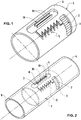
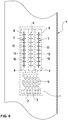
- this metering element 1 shows a metering element 1, which has the shape of a hollow cylinder.
- this metering element 1 comprises an inlet area 2, which is equipped with a filter 3. Through this filter 3, the water from the drip irrigation pipe 4 enters the inlet area 2.
- a metering area 5 Connected to this inlet area 2 is a metering area 5, in which the pressure of the water flowing through is reduced in a known manner. From this metering area 5 the water reaches the outlet area 6, from which the water can be released dropwise into the environment.
- the metering element 1 is inserted into the drip irrigation tube 4 in a known manner, the surfaces of the metering element 1 are connected to the wall 9 of the drip irrigation tube 4 in a known manner, in particular by welding, which takes place in a known manner during the manufacturing process of the drip irrigation tube, the outlet opening has the shape of a slot 8, which extends at least over a partial region of the length of the outlet region 6.
- support means 10 are attached in the outlet region 6 of the metering element 1, which in this first embodiment are designed as two ribs 11, which extend along the slot 8 on both sides, and whose function is described below.
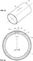
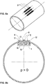
- the metering element 1 can be seen, which has the shape of a hollow cylinder which is inserted into the drip irrigation pipe 4 and connected to it.
- the entry area 2 of the metering element 1 and the slot 8 in the wall 9 are also visible.
- the support means are formed by the two ribs 11. These two ribs 11 are each arranged below an edge region 12 of the slot 8.
- the pressure inside the drip irrigation tube 4 is equal to 0 here, because of the elastic material from which this drip irrigation tube 4 is formed, for example polyethylene, the edge regions 12 which delimit the slot 8 lie on one another, the slot 8 is closed.
- Fig. 3a can be seen, which shows the drip irrigation pipe 1 with the slot 8 made therein Fig.
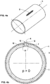
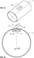
- Fig. 4b shows the drip irrigation pipe 4 with the dosing element 1 inserted therein, the pressure inside the drip irrigation pipe 4 being greater than 0, which state is reached during the irrigation process.
- the inlet area 2 there is also a slightly higher pressure, as a result of which the two edge areas 12 of the slot 8 are raised to the outside and form an opening, the slot 8 thereby allowing the water to escape from the drip irrigation pipe 4.
- the slot 8 in the drip irrigation pipe 4 is open.
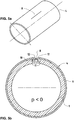
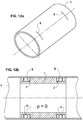
- the pressure inside the drip irrigation pipe 4 collapses and becomes less than 0, as shown in FIG Fig. 5b is shown.
- the drip irrigation pipes 4 are not aligned absolutely horizontally, which is usually the case, the residual water located in the drip irrigation pipe 4 will run at the lowest point of the irrigation system, as a result of which the negative pressure within the drip irrigation pipes 4 comes about.
- This negative pressure can also be found in inlet area 2, a suction effect thus arises on the slot 8, the edge regions 12 of the slot 8 are bent inwards.
- the ribs 11, which form the support means 10, prevent excessive bending, the slot 8 thus remains closed even in this state. This prevents any dirt particles from penetrating into the entry area 2 through the slot 8, which particles then enter the metering area 5 ( Fig. 1 ) would land and could block the flow of water through the metering area 5.
- Fig. 6 shows an embodiment in which the dosing element 1 inserted into the drip irrigation tube 4 has the shape of a plate.
- This metering element in turn comprises an inlet area 2, a filter 3, a metering area 5 and three outlet areas 6 arranged next to one another.
- an outlet opening 7 in the form of a slot 8 is made in the wall 9 of the drip irrigation pipe 4.
- support means 10 are in turn attached, which are designed here as cams 13, each extending across the slot 8 and spaced apart along the slot 8.
- the edge regions 12 of the slots 8 are bent outwards during the irrigation process and if the pressure inside the drip irrigation pipe 4 is greater than 0, the slots 8 are opened and the water can escape through these slots 8.
- the metering element 1 is formed from a hollow cylinder which, as has been described above, is inserted into the drip irrigation pipe 4 and connected to it.
- This metering element 1 has an inlet area 2, in which the filter 3 is arranged, through which the water from the interior of the drip irrigation pipe is conducted via the metering areas 5 into the outlet areas 6.
- These entry areas 6 are designed as grooves 14, which extend over the entire circumference of the metering element 1.
- two parallel ribs 15 are attached, which support the edge regions of the slots 8, which form the outlet openings 7, as will be seen later.
- the slots 8 are arranged transversely to the longitudinal axis of the drip irrigation pipe 4.
- the slots 8 are closed, as previously described.
- the edge regions 12 of the slots 8 are bent outwards so that water can emerge from the slots 8 for irrigation.
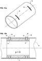
- Fig. 15 shows a drip irrigation pipe 4, in each of which a slot 8 is arranged in the longitudinal direction of the pipe for each metering element.
- Fig. 16 shows that to that in Fig. 15 shown slot 8, a metering element 1 is attached in the form of a plate, with inlet area 2, metering area 5 and outlet area 6, wherein two longitudinal ribs 16 are arranged along the slot 8, which can support the edge regions 12 of the slot 8.
- Fig. 17 shows the same arrangement as in Fig. 16
- the support means 10 in the metering element 1 are designed as cams 13 which can support the edge regions 12 of the slot 8.
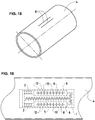
- the metering element 1 comprises two inlet areas 2, a metering area 5 and two outlet areas 6, the outlet areas 6 being aligned parallel to one another and in the longitudinal direction of the drip irrigation pipe 4.
- the slots 8 are arranged in the area of the outlet areas 6, the edge areas 12 of these slots 8 are supported by cams 13 which are provided along the slots 8 in the metering element 1.
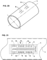
- the metering element 1 has two inlet areas 2, from which the water reaches a centrally arranged metering area 5, via a branching the water reaches the two outlet areas 6, which are aligned parallel to one another.
- two slots 8 are made in the wall 9 of the drip irrigation pipe 4, the edge areas 12 of which are supported by cams 13.
Landscapes
- Life Sciences & Earth Sciences (AREA)
- Soil Sciences (AREA)
- Engineering & Computer Science (AREA)
- Water Supply & Treatment (AREA)
- Environmental Sciences (AREA)
- Infusion, Injection, And Reservoir Apparatuses (AREA)
Description
Die vorliegende Erfindung bezieht sich auf ein Tropfbewässerungsrohr mit darin eingesetzten Dosierelementen, die mit der Wandung des Tropfbewässerungsrohres verbunden sind, welche Dosierelemente jeweils Eintrittsbereiche, durch welche das Wasser vom Rohr in die Dosierelemente gelangt, Dosierbereiche, in welchen eine Druckreduzierung des durchfliessenden Wassers erfolgt, und Austrittbereiche, durch welche das Wasser über in der Rohrwandung angebrachte Austrittöffnungen aus den Tropfbewässerungsrohr austritt, umfassen.The present invention relates to a drip irrigation pipe with metering elements inserted therein, which are connected to the wall of the drip irrigation pipe, which metering elements each have entry areas through which the water from the pipe enters the metering elements, metering areas in which the pressure of the water flowing through is reduced, and Outlet areas through which the water exits the drip irrigation pipe via outlet openings provided in the pipe wall.
Derartige Tropfbewässerungsrohre sind in vielfältiger Weise bekannt, wie in
Während des Bewässerungsvorgangs steht das Wasser in den Tropfbewässerungsrohren unter einem bestimmten Druck. Über die Druckreduzierung in den Dosierbereichen der Dosierelemente tritt das Wasser tropfweise durch die Austrittöffnungen aus dem Tropfbewässerungsrohren aus. Wenn die Bewässerung über die Tropfbewässerungsrohre unterbrochen oder abgestellt wird, baut sich der Druck des Wassers in den Tropfbewässerungsrohren ab. Da die Tropfbewässerungsrohre über deren Längen in den zubewässenden Kulturen den Unhebenheiten oder Neigungen des Bodens folgen, wird das in den Tropfbewässerungsrohren sich befindende Wasser an die tiefste Stelle des Tropfbewässerungsrohres zurück laufen. Dadurch entsteht in gewissen Bereichen der Tropfbewässerungsrohre ein Unterdruck, an den Austrittöffnungen der Tropfbewässerungsrohre entsteht dadurch eine Ansaugwirkung, diese Ansaugwirkung kann zur Folge haben, dass Verschmutzungsteilchen aus dem umliegenden Erdreich angesaugt und in den Dosierbereich der Dosierelemente gelangen kann. Dies kann zu einer Verstopfung des Dosierelementes führen, die erwünschte Bewässerung der im Bereich dieser Austrittöffnungen sich befindenden Pflanzen wird gestört, was zu einem Verkümmern dieser Pflanze oder sogar zum Absterben führen kann.During the irrigation process, the water in the drip irrigation pipes is under a certain pressure. Through the pressure reduction in the dosing areas of the dosing elements, the water emerges dropwise through the outlet openings from the drip irrigation pipes. If irrigation through the drip irrigation pipes is interrupted or switched off, the pressure of the water in the drip irrigation pipes decreases. Since the drip irrigation pipes follow the unevenness or inclinations of the soil over their lengths in the crops to be irrigated, the water in the drip irrigation pipes will run back to the lowest point of the drip irrigation pipe. This creates a negative pressure in certain areas of the drip irrigation pipes, this creates a suction effect at the outlet openings of the drip irrigation pipes, this suction effect can result in dirt particles being sucked in from the surrounding earth and entering the metering area of the metering elements. This can lead to blockage of the metering element, the desired irrigation of the The area of these outlet openings of the plants is disturbed, which can lead to this plant atrophying or even to death.
Es sind verschiedene Arten von Tropfbewässerungsrohren bekannt. Insbesondere bei dünnwandigen Rohren werden Dosierelemente eingesetzt, welche die Form eines Plättchens oder fortlaufenden Bandes aufweisen, in welche die Strukturen des Dosierelementes eingeprägt sind. Diese Tropfbewässerungsrohre sind im "Ruhezustand" flach gedrückt. Bei dickwandigeren Tropfbewässerungsrohren, die beispielsweise ins Erdreich hinein verlegt werden, werden üblicherweise Dosierelemente eingesetzt, die eine hohlzylindrische Form aufweisen. In diese hohlzylindrischen Dosierelemente sind die Dosierstrukturen eingeformt.Different types of drip irrigation pipes are known. In the case of thin-walled tubes in particular, metering elements are used which have the shape of a plate or continuous band into which the structures of the metering element are stamped. These drip irrigation pipes are pressed flat in the "idle state". In the case of thick-walled drip irrigation pipes, which are laid, for example, in the ground, metering elements are usually used which have a hollow cylindrical shape. The metering structures are molded into these hollow cylindrical metering elements.
Bei all diesen Tropfbewässerungsrohren kann im Bereich der Austrittöffnungen aus den oben aufgeführten Gründen die beschriebene Saugwirkung auftreten.With all of these drip irrigation pipes, the suction effect described can occur in the area of the outlet openings for the reasons listed above.
Die Aufgabe der vorliegenden Erfindung besteht darin, die Tropfbewässerungsrohre derart auszugestalten, dass möglichst vermieden wird, dass in die Dosierbereiche der Dosierelemente durch die Austrittöffnungen Verschmutzungsteilchen eindringen und in die Dosierbereiche gelangen können, wodurch das entsprechende Dosierelement verstopft werden könnte.The object of the present invention is to design the drip irrigation pipes in such a way that it is avoided as far as possible that dirt particles can penetrate into the metering areas of the metering elements through the outlet openings and get into the metering areas, as a result of which the corresponding metering element could become blocked.
Erfindungsgemäss erfolgt die Lösung dieser Aufgabe dadurch, dass die Austrittöffnungen die Form eines geschlossenen Schlitzes aufweisen, dessen Randbereiche beim Bewässerungsvorgang nach aussen angehoben sind und eine Öffnung bilden, und die beim Beendigen oder Unterbrechen des Bewässerungsvorgangs durch Abstützmittel derart abgestützt sind, dass ein Einbiegen der Randbereiche des Schlitzes gegen die Dosierelemente begrenzt ist und die schlitzförmigen Austrittsöffnungen verschlossen bleiben.According to the invention, this object is achieved in that the outlet openings are in the form of a closed slot, the edge regions of which are raised outwards during the irrigation process and form an opening, and which are supported by supporting means when the irrigation process is ended or interrupted in such a way that the edge regions bend in the slot against the metering elements is limited and the slot-shaped outlet openings remain closed.
Die schlitzförmige Ausgestaltung der Austrittöffnungen ermöglicht, dass beim Bewässerungsvorgang die Randbereiche des Schlitzes nach aussen aufgebogen werden, sodass der Schlitz geöffnet wird und das Wasser austreten kann. Bei der vorgängig beschriebenen Saugwirkung, die im Bereich des Schlitzes beim Beendigen und Unterbrechen des Bewässerungsvorgangs durch den Druckabfall in Tropfbewässerungsrohr und den Rücklauf des Wassers auftreten kann, würden die Randbereiche des Schlitzes nach innen gegen das Dosierelement eingebogen und eine Öffnung bilden, durch die in diesen Randbereichen des Schlitzes angebrachten Abstützelemente wird ein derartiges Einbiegen dieser Randbereiche vermieden, die schlitzförmige Austrittöffnung bleibt somit verschlossen, das Eindringen von Verschmutzungsteilchen in das Dosierelement kann dadurch praktisch ausgeschlossen werden, die Funktion der einzelnen Dosierelemente in den Tropfbewässerungsrohren ist gewährleistet.The slot-shaped design of the outlet openings enables the edge regions of the slot to be bent outwards during the irrigation process, so that the slot is opened and the water can leak. In the case of the suction effect described above, which occurs in the area of the slot when the irrigation process is ended and interrupted due to the pressure drop in the drip irrigation pipe and the return of the water, the edge areas of the slot would be bent inwards against the metering element and form an opening, by means of the support elements provided in these edge areas of the slot, such a bending of these edge areas is avoided and the slot-shaped outlet opening remains thus closed, the penetration of dirt particles into the metering element can be practically excluded, the function of the individual metering elements in the drip irrigation pipes is guaranteed.
In vorteilhafter Weise sind die Abstützmittel an den Dosierelementen angeformt, was eine einfache Herstellung ermöglicht.The support means are advantageously formed on the metering elements, which enables simple manufacture.
In vorteilhafter Weise sind die Abstützmittel aus Nocken gebildet, die entlang des Schlitzes an den Dosierelementen angeordnet sind. Über diese Nocken wird der jeweilige Randbereich des Schlitzes gegen das Einbiegen abgestützt, der Wasserdurchlauf ist optimal gewährleistet.The support means are advantageously formed from cams which are arranged along the slot on the metering elements. The respective edge area of the slot is supported against bending in via these cams, the water flow is optimally guaranteed.
Die Abstützmittel können auch als Rippen ausgebildet sein, die längs zum jeweiligen Schlitz an den Dosierelementen angeordnet sind, wodurch eine optimale Abstützung der Randbereiche erreichbar ist.The support means can also be designed as ribs which are arranged along the respective slot on the metering elements, as a result of which optimal support of the edge regions can be achieved.
Eine weitere vorteilhafte Ausgestaltung der Erfindung besteht darin, dass jedes Dosierelement mehrere Austrittbereiche umfassen kann. Dadurch kann über ein Dosierelement in einfacher Weise mehr Wasser ausgelassen werden.A further advantageous embodiment of the invention consists in the fact that each metering element can comprise several outlet areas. As a result, more water can easily be discharged via a metering element.
Das Auslassen einer grösseren Menge von Wasser wird zusätzlich auch dadurch erreicht, dass für jeden Austrittbereich in der Rohrwandung mehr als eine Austrittöffnung in Form eines Schlitzes vorgesehen ist.The discharge of a larger amount of water is also achieved in that more than one outlet opening in the form of a slot is provided for each outlet region in the tube wall.
In vorteilhafter Weise weisen die Dosierelemente die Form eines Hohlzylinders auf, was insbesondere bei dickwandigeren Tropfbewässerungsrohren vorteilhaft ist.The metering elements advantageously have the shape of a hollow cylinder, which is particularly advantageous in the case of thick-walled drip irrigation pipes.
Bei dünnwandigeren Tropfbewässerungsrohren können die Dosierelemente in vorteilhafter Weise die Form eines Plättchens oder Bandes aufweisen, wodurch die Tropfbewässerungsrohre bei Nichtgebrauch flach gedrückt sein können.In the case of thin-walled drip irrigation pipes, the metering elements can advantageously have the shape of a plate or tape, as a result of which the drip irrigation pipes can be pressed flat when not in use.
Je nach Ausgestaltung der Dosierelemente und wie die Austrittbereiche in diesen Dosierelementen angeordnet sein können, können die Schlitze parallel zur Längsachse des Tropfbewässerungsrohres oder quer zur Längsachse des Tropfbewässerungsrohres ausgerichtet sein.Depending on the configuration of the metering elements and how the outlet areas can be arranged in these metering elements, the slots can be aligned parallel to the longitudinal axis of the drip irrigation pipe or transversely to the longitudinal axis of the drip irrigation pipe.
Ausführungsformen der Erfindung werden nachfolgend an Hand der beiliegenden Zeichnung beispielhaft näher erläutert.Embodiments of the invention are explained in more detail below with reference to the accompanying drawings.
Es zeigt
-
Fig. 1 schematisch und in räumlicher Darstellung ein Dosierelement gemäss einer ersten Ausführungsform der Erfindung; -
Fig. 2 in räumlicher Darstellung das Dosierelement gemässFig. 1 im in das Tropfbewässerungsrohr eingesetzten Zustand; -
Fig. 3a und Fig. 3b die Darstellung der Austrittsöffnung in Form eines Schlitzes dieser ersten Ausführungsform, wenn der Druck innerhalb des Tropfbewässerungsrohres gleich 0 ist; -
Fig. 4a und Fig. 4b die Darstellung der Austrittsöffnung in Form eines Schlitzes dieser ersten Ausführungsform, wenn der Druck innerhalb des Tropfbewässerungsrohres grösser als 0 ist; -
Fig. 5a und Fig. 5b die Darstellung der Austrittsöffnung in Form eines Schlitzes dieser ersten Ausführungsform, wenn der Druck innerhalb des Tropfbewässerungsrohres kleiner als O ist; -
Fig. 6 in schematischer Darstellung eine zweite Ausführungsform der Erfindung, bei welcher das Dosierelement als Plättchen ausgebildet ist und drei Austrittsöffnungen in Form eines Schlitzes aufweist; -
Fig. 7a und Fig. 7b die Darstellung der Austrittsöffnungen in Form eines Schlitzes dieser zweiten Ausführungsform, wenn der Druck innerhalb des Tropfbewässerungsrohres gleich 0 ist; -
Fig. 8a und Fig. 8b die Darstellung der Austrittsöffnungen in Form eines Schlitzes dieser zweiten Ausführungsform, wenn der Druck innerhalb des Tropfbewässerungsrohres grösser als 0 ist; -
Fig. 9a und Fig. 9b die Darstellung der Austrittsöffnungen in Form eines Schlitzes dieser zweiten Ausführungsform, wenn der Druck innerhalb des Tropfbewässerungsrohres kleiner als 0 ist; -
Fig. 10 schematisch und in räumlicher Darstellung ein Dosierelement gemäss einer dritten Ausführungsform der Erfindung; -
Fig. 11 schematisch das Dosierelement gemässFig. 10 im in das Tropfbewässerungsrohr eingesetzten Zustand; -
Fig. 12a und Fig. 12b die Darstellung der Austrittsöffnungen in Form eines Schlitzes dieser dritten Ausführungsform, wenn der Druck innerhalb des Tropfbewässerungsrohres gleich 0 ist; -
Fig. 13a und Fig. 13b die Darstellung der Austrittsöffnungen in Form eines Schlitzes dieser dritten Ausführungsform, wenn der Druck innerhalb des Tropfbewässerungsrohres grösser als 0 ist; -
Fig. 14a und Fig. 14b die Darstellung der Austrittsöffnungen in Form eines Schlitzes dieser dritten Ausführungsform, wenn der Druck innerhalb des Tropfbewässerungsrohres kleiner als 0 ist; -
Fig. 15 bis Fig. 17 eine vierte Ausführungsform der Erfindung, bei welcher das Dosierelement die Form eines Plättchens aufweist und eine Austrittsöffnung in Form eines Schlitzes vorgesehen ist; -
Fig. 18 und Fig. 19 eine fünfte Ausführungsform der Erfindung, bei welcher das Dosierelement als Plättchen ausgebildet ist und zwei Austrittsöffnungen in Form eines Schlitzes aufweist; und -
Fig. 20 und Fig. 21 eine sechste Ausführungsform der Erfindung, bei welcher das Dosierelement als Plättchen ausgebildet ist mit vier Austrittsöffnungen in Form eines Schlitzes.
-
Fig. 1 schematically and in spatial representation a metering element according to a first embodiment of the invention; -
Fig. 2 in spatial representation the dosing element according toFig. 1 when inserted into the drip irrigation pipe; -
3a and 3b the representation of the outlet opening in the form of a slot of this first embodiment when the pressure inside the drip irrigation tube is equal to 0; -
4a and 4b the representation of the outlet opening in the form of a slot of this first embodiment when the pressure inside the drip irrigation pipe is greater than 0; -
5a and 5b the representation of the outlet opening in the form of a slot of this first embodiment when the pressure inside the drip irrigation pipe is less than 0; -
Fig. 6 a schematic representation of a second embodiment of the invention, in which the metering element is designed as a plate and has three outlet openings in the form of a slot; -
7a and 7b the representation of the outlet openings in the form of a slot of this second embodiment when the pressure inside the drip irrigation tube is equal to 0; -
8a and 8b the representation of the outlet openings in the form of a slot of this second embodiment when the pressure inside the drip irrigation pipe is greater than 0; -
9a and 9b the representation of the outlet openings in the form of a slot of this second embodiment when the pressure inside the drip irrigation pipe is less than 0; -
Fig. 10 schematically and in spatial representation a metering element according to a third embodiment of the invention; -
Fig. 11 schematically the dosing element according toFig. 10 when inserted into the drip irrigation pipe; -
Figures 12a and 12b the representation of the outlet openings in the form of a slot of this third embodiment when the pressure inside the drip irrigation tube is equal to 0; -
Figures 13a and 13b the representation of the outlet openings in the form of a slot of this third embodiment when the pressure inside the drip irrigation pipe is greater than 0; -
14a and 14b the representation of the outlet openings in the form of a slot of this third embodiment when the pressure inside the drip irrigation pipe is less than 0; -
15 to 17 a fourth embodiment of the invention, in which the metering element has the shape of a plate and an outlet opening is provided in the form of a slot; -
18 and 19 a fifth embodiment of the invention, in which the metering element is designed as a plate and has two outlet openings in the form of a slot; and -
20 and 21 a sixth embodiment of the invention, in which the metering element is designed as a plate with four outlet openings in the form of a slot.
Wie aus
Wie aus den
Aus der
Wenn der Bewässerungsvorgang beendet ist, fällt der Druck innerhalb des Tropfbewässerungsrohres 4 zusammen und wird kleiner als 0, wie dies in
Wie aus den
Wie aus den
Wenn der Bewässerungsvorgang abgeschlossen ist und innerhalb des Tropfbewässerungsrohres 4 wie vorgängig erläutert ein Unterdruck entsteht, werden die Randbereiche 12 der Schlitze 8 gegen das Dosierelement 1 hin eingebogen, diese Einbiegung erfolgt nur soweit, bis die Randbereiche 12 auf den Nocken 13 abgestützt werden, welche Nocken 13 die Abstützmittel 10 bilden. Die Schlitze 8 werden dadurch geschlossen, ein Eindringen von Verunreinigungen wird vermieden.When the irrigation process is completed and a negative pressure develops within the
Aus den
Wenn innerhalb des Tropfbewässerungsrohres 4 der Druck 0 ist, wie dies in den
Wenn der Bewässerungsvorgang abgeschlossen ist und der Druck im Tropfbewässerungsrohr kleiner als 0 wird, wie dies in den
In den
In den
Diese vorgängig beschriebenen Ausführungsformen zeigen, dass die die Austrittöffnung bildenden Schlitze durch Abstützmittel verschlossen bleiben, wenn innerhalb des Rohres ein Unterdruck auftritt, wodurch vermieden wird, dass Verunreinigungen in die Dosierelemente eindringen und diese verstopfen können. Ausserdem zeigen diese Ausführungsformen, dass unterschiedliche Dosierelemente eingesetzt werden können, so dass die Anzahl der Schlitze, durch welche das Wasser austreten kann, wie auch deren Ausrichtung praktisch beliebig gestaltet werden können, je nach den Anforderungen, die an das Bewässerungssystem gestellt werden.These previously described embodiments show that the slots forming the outlet opening remain closed by support means if a negative pressure occurs inside the tube, thereby preventing contaminants from entering the metering elements and the latter can clog. In addition, these embodiments show that different metering elements can be used, so that the number of slots through which the water can escape, as well as their orientation, can be designed practically as desired, depending on the requirements placed on the irrigation system.
Claims (10)
- Drip irrigation tube (4) with dosing elements (1) inserted therein, which dosing elements are connected to the walling (9) of the drip irrigation tube (4), which dosing elements (1) each comprise inlet regions (2), through which the water passes from the tube (4) into the dosing elements (1), dosing regions (5), in which a pressure reduction of the through-flowing water takes place, and outlet regions (6), through which the water issues out of the drip irrigation tube (4) via outlet openings (7) made in the tube walling (9), characterized in that the outlet openings (7) are in the form of a slit (8), the edge regions (12) of which, during the irrigation procedure, are outwardly raised and form an opening, and, when the irrigation procedure is ended or interrupted, are supported by supporting means (10) in such a manner as to limit bending of the edge regions (12) of the slit (8) towards the dosing elements and the slit-shaped outlet openings remain closed.
- Drip irrigation tube (4) with dosing elements (1) inserted therein, according to claim 1, characterized in that the supporting means (10) are integrally formed on the dosing elements (1).
- Drip irrigation tube (4) with dosing elements (1) inserted therein, according to claim 1 or 2, characterized in that the supporting means (10) are formed from protrusions (13) which are arranged along the slit (8) on the dosing elements (1).
- Drip irrigation tube (4) with dosing elements (1) inserted therein, according to claim 1 or 2, characterized in that the supporting means (10) are designed as ribs (15; 16), which are arranged longitudinally with respect to the respective slit (8) on the dosing elements (1).
- Drip irrigation tube (4) with dosing elements (1) inserted therein, according to one of claims 1 to 4, characterized in that each dosing element (1) comprises at least one outlet region (6).
- Drip irrigation tube (4) with dosing elements (1) inserted therein, according to one of claims 1 to 5, characterized in that at least one outlet opening (7) in the form of a slit (8) is provided for each outlet region (6) in the tube walling (9).
- Drip irrigation tube (4) with dosing elements (1) inserted therein, according to one of claims 1 to 6, characterized in that the dosing elements (1) are in the form of a hollow cylinder.
- Drip irrigation tube (4) with dosing elements (1) inserted therein, according to one of claims 1 to 6, characterized in that the dosing elements (1) are in the form of a disk or band.
- Drip irrigation tube (4) with dosing elements (1) inserted therein, according to one of claims 1 to 8, characterized in that the slits (8) are oriented parallel to the longitudinal axis of the drip irrigation tube (4).
- Drip irrigation tube (4) with dosing elements (1) inserted therein, according to one of claims 1 to 7, characterized in that the slits (8) are oriented transversely to the longitudinal axis of the drip irrigation tube (4).
Priority Applications (5)
| Application Number | Priority Date | Filing Date | Title |
|---|---|---|---|
| ES14171418T ES2788600T3 (en) | 2014-06-05 | 2014-06-05 | Drip irrigation tube with inserted dosing elements |
| PT141714188T PT2952091T (en) | 2014-06-05 | 2014-06-05 | Drip irrigation pipe with dosing elements inserted therein |
| RS20200352A RS60212B1 (en) | 2014-06-05 | 2014-06-05 | Drip irrigation pipe with dosing elements inserted therein |
| EP14171418.8A EP2952091B1 (en) | 2014-06-05 | 2014-06-05 | Drip irrigation pipe with dosing elements inserted therein |
| CY20201100299T CY1122903T1 (en) | 2014-06-05 | 2020-03-30 | IRRIGATION DRIP HOSE WITH DOSING DATA INTRODUCED ON IT |
Applications Claiming Priority (1)
| Application Number | Priority Date | Filing Date | Title |
|---|---|---|---|
| EP14171418.8A EP2952091B1 (en) | 2014-06-05 | 2014-06-05 | Drip irrigation pipe with dosing elements inserted therein |
Publications (2)
| Publication Number | Publication Date |
|---|---|
| EP2952091A1 EP2952091A1 (en) | 2015-12-09 |
| EP2952091B1 true EP2952091B1 (en) | 2020-02-05 |
Family
ID=50927955
Family Applications (1)
| Application Number | Title | Priority Date | Filing Date |
|---|---|---|---|
| EP14171418.8A Active EP2952091B1 (en) | 2014-06-05 | 2014-06-05 | Drip irrigation pipe with dosing elements inserted therein |
Country Status (5)
| Country | Link |
|---|---|
| EP (1) | EP2952091B1 (en) |
| CY (1) | CY1122903T1 (en) |
| ES (1) | ES2788600T3 (en) |
| PT (1) | PT2952091T (en) |
| RS (1) | RS60212B1 (en) |
Families Citing this family (13)
| Publication number | Priority date | Publication date | Assignee | Title |
|---|---|---|---|---|
| US7648085B2 (en) | 2006-02-22 | 2010-01-19 | Rain Bird Corporation | Drip emitter |
| US9877440B2 (en) | 2012-03-26 | 2018-01-30 | Rain Bird Corporation | Elastomeric emitter and methods relating to same |
| US10440903B2 (en) | 2012-03-26 | 2019-10-15 | Rain Bird Corporation | Drip line emitter and methods relating to same |
| US10631473B2 (en) | 2013-08-12 | 2020-04-28 | Rain Bird Corporation | Elastomeric emitter and methods relating to same |
| US10285342B2 (en) | 2013-08-12 | 2019-05-14 | Rain Bird Corporation | Elastomeric emitter and methods relating to same |
| US9883640B2 (en) | 2013-10-22 | 2018-02-06 | Rain Bird Corporation | Methods and apparatus for transporting elastomeric emitters and/or manufacturing drip lines |
| US10330559B2 (en) | 2014-09-11 | 2019-06-25 | Rain Bird Corporation | Methods and apparatus for checking emitter bonds in an irrigation drip line |
| US10375904B2 (en) | 2016-07-18 | 2019-08-13 | Rain Bird Corporation | Emitter locating system and related methods |
| WO2018140772A1 (en) | 2017-01-27 | 2018-08-02 | Rain Bird Corporation | Pressure compensation members, emitters, drip line and methods relating to same |
| TR201706925A2 (en) * | 2017-05-11 | 2018-11-21 | Drts Sulama Ueruenleri Ve Teknolojileri Sanayi Ticaret Anonim Sirketi | Construction of a dripper for use in agricultural irrigation |
| US10626998B2 (en) | 2017-05-15 | 2020-04-21 | Rain Bird Corporation | Drip emitter with check valve |
| USD883048S1 (en) | 2017-12-12 | 2020-05-05 | Rain Bird Corporation | Emitter part |
| US11985924B2 (en) | 2018-06-11 | 2024-05-21 | Rain Bird Corporation | Emitter outlet, emitter, drip line and methods relating to same |
Family Cites Families (5)
| Publication number | Priority date | Publication date | Assignee | Title |
|---|---|---|---|---|
| US6382530B1 (en) * | 2000-07-10 | 2002-05-07 | Nelson Irrigation Corporation | Pressure compensating drip tape |
| US6736337B2 (en) * | 2002-02-08 | 2004-05-18 | The Toro Company | Pressure compensating drip irrigation hose |
| IL212105A (en) * | 2011-04-03 | 2016-07-31 | Einav Zvi | Integral dripper with an elongated exit pool |
| GB2496832B (en) * | 2011-05-16 | 2013-11-13 | Uri Alkalay | Cylindrical drip irrigation emitter |
| IL221089A (en) * | 2012-07-24 | 2016-05-31 | Einav Zvi | Integral drip irrigation emitter with an easy spreadable exit pool |
-
2014
- 2014-06-05 RS RS20200352A patent/RS60212B1/en unknown
- 2014-06-05 EP EP14171418.8A patent/EP2952091B1/en active Active
- 2014-06-05 ES ES14171418T patent/ES2788600T3/en active Active
- 2014-06-05 PT PT141714188T patent/PT2952091T/en unknown
-
2020
- 2020-03-30 CY CY20201100299T patent/CY1122903T1/en unknown
Non-Patent Citations (1)
| Title |
|---|
| None * |
Also Published As
| Publication number | Publication date |
|---|---|
| EP2952091A1 (en) | 2015-12-09 |
| PT2952091T (en) | 2020-03-31 |
| ES2788600T3 (en) | 2020-10-22 |
| RS60212B1 (en) | 2020-06-30 |
| CY1122903T1 (en) | 2021-10-29 |
Similar Documents
| Publication | Publication Date | Title |
|---|---|---|
| EP2952091B1 (en) | Drip irrigation pipe with dosing elements inserted therein | |
| DE2431516C3 (en) | Device for dispensing fluids | |
| EP2054558B1 (en) | Drainage device | |
| DE2707233A1 (en) | IRRIGATION DEVICE | |
| DE2224320A1 (en) | Output head for irrigation systems or the like | |
| DE2815628A1 (en) | INTEGRAL DROP IRRIGATION SYSTEM | |
| DE2852108A1 (en) | PIPE FOUNTAIN FILTER | |
| DE2011409A1 (en) | Coupling sleeve for coupling with a connecting sleeve | |
| EP1918576B1 (en) | Fuel filter | |
| DE202017105379U1 (en) | aerator | |
| DE2514233A1 (en) | DUESE FOR IRRIGATION SYSTEMS | |
| EP2508686A1 (en) | Retention assembly for precipitation and waste water | |
| DE10063283A1 (en) | Sieve filters for fluid lines, in particular for hydraulic pressure lines in internal combustion engines | |
| DE2431513C3 (en) | Fluid dispensing device operating with a throttling effect | |
| EP2764768B1 (en) | Drip irrigation tube with metering elements | |
| EP3517211B1 (en) | Shower head with pressure relief valve | |
| DE102017120521A1 (en) | aerator | |
| DE102013022114B4 (en) | filter means | |
| DE102016104557A1 (en) | Vacuum cleaner suction tube | |
| DE102017128758A1 (en) | Sanitary insert unit | |
| DE102011078560A1 (en) | Apparatus for guiding line through opening in hike, has anchor body for receiving seal, where tubular element is provided for guiding line to end coupled to anchor body | |
| DE19519106B4 (en) | throttling device | |
| DE102016205647A1 (en) | Ring gate for a hydraulic machine and method for closing | |
| DE3923028C2 (en) | Throttle element for pressure lines | |
| DE202007014407U1 (en) | Spray nozzle with the possibility of spraying water on all sides |
Legal Events
| Date | Code | Title | Description |
|---|---|---|---|
| PUAI | Public reference made under article 153(3) epc to a published international application that has entered the european phase |
Free format text: ORIGINAL CODE: 0009012 |
|
| AK | Designated contracting states |
Kind code of ref document: A1 Designated state(s): AL AT BE BG CH CY CZ DE DK EE ES FI FR GB GR HR HU IE IS IT LI LT LU LV MC MK MT NL NO PL PT RO RS SE SI SK SM TR |
|
| AX | Request for extension of the european patent |
Extension state: BA ME |
|
| RIN1 | Information on inventor provided before grant (corrected) |
Inventor name: LOEBINGER, AHAI Inventor name: KERTSCHER, EBERHARD |
|
| 17P | Request for examination filed |
Effective date: 20160606 |
|
| RBV | Designated contracting states (corrected) |
Designated state(s): AL AT BE BG CH CY CZ DE DK EE ES FI FR GB GR HR HU IE IS IT LI LT LU LV MC MK MT NL NO PL PT RO RS SE SI SK SM TR |
|
| STAA | Information on the status of an ep patent application or granted ep patent |
Free format text: STATUS: EXAMINATION IS IN PROGRESS |
|
| 17Q | First examination report despatched |
Effective date: 20170217 |
|
| GRAP | Despatch of communication of intention to grant a patent |
Free format text: ORIGINAL CODE: EPIDOSNIGR1 |
|
| STAA | Information on the status of an ep patent application or granted ep patent |
Free format text: STATUS: GRANT OF PATENT IS INTENDED |
|
| INTG | Intention to grant announced |
Effective date: 20190909 |
|
| GRAS | Grant fee paid |
Free format text: ORIGINAL CODE: EPIDOSNIGR3 |
|
| GRAA | (expected) grant |
Free format text: ORIGINAL CODE: 0009210 |
|
| STAA | Information on the status of an ep patent application or granted ep patent |
Free format text: STATUS: THE PATENT HAS BEEN GRANTED |
|
| AK | Designated contracting states |
Kind code of ref document: B1 Designated state(s): AL AT BE BG CH CY CZ DE DK EE ES FI FR GB GR HR HU IE IS IT LI LT LU LV MC MK MT NL NO PL PT RO RS SE SI SK SM TR |
|
| REG | Reference to a national code |
Ref country code: GB Ref legal event code: FG4D Free format text: NOT ENGLISH |
|
| REG | Reference to a national code |
Ref country code: AT Ref legal event code: REF Ref document number: 1229298 Country of ref document: AT Kind code of ref document: T Effective date: 20200215 |
|
| REG | Reference to a national code |
Ref country code: DE Ref legal event code: R096 Ref document number: 502014013548 Country of ref document: DE |
|
| REG | Reference to a national code |
Ref country code: IE Ref legal event code: FG4D Free format text: LANGUAGE OF EP DOCUMENT: GERMAN |
|
| REG | Reference to a national code |
Ref country code: RO Ref legal event code: EPE |
|
| REG | Reference to a national code |
Ref country code: PT Ref legal event code: SC4A Ref document number: 2952091 Country of ref document: PT Date of ref document: 20200331 Kind code of ref document: T Free format text: AVAILABILITY OF NATIONAL TRANSLATION Effective date: 20200323 Ref country code: CH Ref legal event code: EP |
|
| REG | Reference to a national code |
Ref country code: CH Ref legal event code: NV Representative=s name: BOVARD AG PATENT- UND MARKENANWAELTE, CH |
|
| REG | Reference to a national code |
Ref country code: GR Ref legal event code: EP Ref document number: 20200401128 Country of ref document: GR Effective date: 20200615 |
|
| REG | Reference to a national code |
Ref country code: NL Ref legal event code: MP Effective date: 20200205 |
|
| PG25 | Lapsed in a contracting state [announced via postgrant information from national office to epo] |
Ref country code: NO Free format text: LAPSE BECAUSE OF FAILURE TO SUBMIT A TRANSLATION OF THE DESCRIPTION OR TO PAY THE FEE WITHIN THE PRESCRIBED TIME-LIMIT Effective date: 20200505 Ref country code: FI Free format text: LAPSE BECAUSE OF FAILURE TO SUBMIT A TRANSLATION OF THE DESCRIPTION OR TO PAY THE FEE WITHIN THE PRESCRIBED TIME-LIMIT Effective date: 20200205 |
|
| REG | Reference to a national code |
Ref country code: LT Ref legal event code: MG4D |
|
| PG25 | Lapsed in a contracting state [announced via postgrant information from national office to epo] |
Ref country code: HR Free format text: LAPSE BECAUSE OF FAILURE TO SUBMIT A TRANSLATION OF THE DESCRIPTION OR TO PAY THE FEE WITHIN THE PRESCRIBED TIME-LIMIT Effective date: 20200205 Ref country code: LV Free format text: LAPSE BECAUSE OF FAILURE TO SUBMIT A TRANSLATION OF THE DESCRIPTION OR TO PAY THE FEE WITHIN THE PRESCRIBED TIME-LIMIT Effective date: 20200205 Ref country code: SE Free format text: LAPSE BECAUSE OF FAILURE TO SUBMIT A TRANSLATION OF THE DESCRIPTION OR TO PAY THE FEE WITHIN THE PRESCRIBED TIME-LIMIT Effective date: 20200205 Ref country code: IS Free format text: LAPSE BECAUSE OF FAILURE TO SUBMIT A TRANSLATION OF THE DESCRIPTION OR TO PAY THE FEE WITHIN THE PRESCRIBED TIME-LIMIT Effective date: 20200605 |
|
| PG25 | Lapsed in a contracting state [announced via postgrant information from national office to epo] |
Ref country code: NL Free format text: LAPSE BECAUSE OF FAILURE TO SUBMIT A TRANSLATION OF THE DESCRIPTION OR TO PAY THE FEE WITHIN THE PRESCRIBED TIME-LIMIT Effective date: 20200205 |
|
| REG | Reference to a national code |
Ref country code: ES Ref legal event code: FG2A Ref document number: 2788600 Country of ref document: ES Kind code of ref document: T3 Effective date: 20201022 |
|
| PG25 | Lapsed in a contracting state [announced via postgrant information from national office to epo] |
Ref country code: LT Free format text: LAPSE BECAUSE OF FAILURE TO SUBMIT A TRANSLATION OF THE DESCRIPTION OR TO PAY THE FEE WITHIN THE PRESCRIBED TIME-LIMIT Effective date: 20200205 Ref country code: CZ Free format text: LAPSE BECAUSE OF FAILURE TO SUBMIT A TRANSLATION OF THE DESCRIPTION OR TO PAY THE FEE WITHIN THE PRESCRIBED TIME-LIMIT Effective date: 20200205 Ref country code: SM Free format text: LAPSE BECAUSE OF FAILURE TO SUBMIT A TRANSLATION OF THE DESCRIPTION OR TO PAY THE FEE WITHIN THE PRESCRIBED TIME-LIMIT Effective date: 20200205 Ref country code: EE Free format text: LAPSE BECAUSE OF FAILURE TO SUBMIT A TRANSLATION OF THE DESCRIPTION OR TO PAY THE FEE WITHIN THE PRESCRIBED TIME-LIMIT Effective date: 20200205 Ref country code: SK Free format text: LAPSE BECAUSE OF FAILURE TO SUBMIT A TRANSLATION OF THE DESCRIPTION OR TO PAY THE FEE WITHIN THE PRESCRIBED TIME-LIMIT Effective date: 20200205 Ref country code: DK Free format text: LAPSE BECAUSE OF FAILURE TO SUBMIT A TRANSLATION OF THE DESCRIPTION OR TO PAY THE FEE WITHIN THE PRESCRIBED TIME-LIMIT Effective date: 20200205 |
|
| REG | Reference to a national code |
Ref country code: DE Ref legal event code: R097 Ref document number: 502014013548 Country of ref document: DE |
|
| PLBE | No opposition filed within time limit |
Free format text: ORIGINAL CODE: 0009261 |
|
| STAA | Information on the status of an ep patent application or granted ep patent |
Free format text: STATUS: NO OPPOSITION FILED WITHIN TIME LIMIT |
|
| 26N | No opposition filed |
Effective date: 20201106 |
|
| PG25 | Lapsed in a contracting state [announced via postgrant information from national office to epo] |
Ref country code: MC Free format text: LAPSE BECAUSE OF FAILURE TO SUBMIT A TRANSLATION OF THE DESCRIPTION OR TO PAY THE FEE WITHIN THE PRESCRIBED TIME-LIMIT Effective date: 20200205 |
|
| PG25 | Lapsed in a contracting state [announced via postgrant information from national office to epo] |
Ref country code: PL Free format text: LAPSE BECAUSE OF FAILURE TO SUBMIT A TRANSLATION OF THE DESCRIPTION OR TO PAY THE FEE WITHIN THE PRESCRIBED TIME-LIMIT Effective date: 20200205 Ref country code: SI Free format text: LAPSE BECAUSE OF FAILURE TO SUBMIT A TRANSLATION OF THE DESCRIPTION OR TO PAY THE FEE WITHIN THE PRESCRIBED TIME-LIMIT Effective date: 20200205 |
|
| GBPC | Gb: european patent ceased through non-payment of renewal fee |
Effective date: 20200605 |
|
| PG25 | Lapsed in a contracting state [announced via postgrant information from national office to epo] |
Ref country code: LU Free format text: LAPSE BECAUSE OF NON-PAYMENT OF DUE FEES Effective date: 20200605 |
|
| REG | Reference to a national code |
Ref country code: BE Ref legal event code: MM Effective date: 20200630 |
|
| PG25 | Lapsed in a contracting state [announced via postgrant information from national office to epo] |
Ref country code: IE Free format text: LAPSE BECAUSE OF NON-PAYMENT OF DUE FEES Effective date: 20200605 Ref country code: GB Free format text: LAPSE BECAUSE OF NON-PAYMENT OF DUE FEES Effective date: 20200605 |
|
| PG25 | Lapsed in a contracting state [announced via postgrant information from national office to epo] |
Ref country code: BE Free format text: LAPSE BECAUSE OF NON-PAYMENT OF DUE FEES Effective date: 20200630 |
|
| REG | Reference to a national code |
Ref country code: AT Ref legal event code: MM01 Ref document number: 1229298 Country of ref document: AT Kind code of ref document: T Effective date: 20200605 |
|
| PG25 | Lapsed in a contracting state [announced via postgrant information from national office to epo] |
Ref country code: AT Free format text: LAPSE BECAUSE OF NON-PAYMENT OF DUE FEES Effective date: 20200605 |
|
| PG25 | Lapsed in a contracting state [announced via postgrant information from national office to epo] |
Ref country code: MT Free format text: LAPSE BECAUSE OF FAILURE TO SUBMIT A TRANSLATION OF THE DESCRIPTION OR TO PAY THE FEE WITHIN THE PRESCRIBED TIME-LIMIT Effective date: 20200205 |
|
| PG25 | Lapsed in a contracting state [announced via postgrant information from national office to epo] |
Ref country code: MK Free format text: LAPSE BECAUSE OF FAILURE TO SUBMIT A TRANSLATION OF THE DESCRIPTION OR TO PAY THE FEE WITHIN THE PRESCRIBED TIME-LIMIT Effective date: 20200205 Ref country code: AL Free format text: LAPSE BECAUSE OF FAILURE TO SUBMIT A TRANSLATION OF THE DESCRIPTION OR TO PAY THE FEE WITHIN THE PRESCRIBED TIME-LIMIT Effective date: 20200205 |
|
| PGFP | Annual fee paid to national office [announced via postgrant information from national office to epo] |
Ref country code: RS Payment date: 20230525 Year of fee payment: 10 Ref country code: RO Payment date: 20230525 Year of fee payment: 10 Ref country code: PT Payment date: 20230525 Year of fee payment: 10 Ref country code: FR Payment date: 20230628 Year of fee payment: 10 Ref country code: DE Payment date: 20230620 Year of fee payment: 10 Ref country code: CY Payment date: 20230601 Year of fee payment: 10 Ref country code: BG Payment date: 20230627 Year of fee payment: 10 |
|
| P01 | Opt-out of the competence of the unified patent court (upc) registered |
Effective date: 20230630 |
|
| PGFP | Annual fee paid to national office [announced via postgrant information from national office to epo] |
Ref country code: TR Payment date: 20230602 Year of fee payment: 10 Ref country code: GR Payment date: 20230621 Year of fee payment: 10 |
|
| PGFP | Annual fee paid to national office [announced via postgrant information from national office to epo] |
Ref country code: IT Payment date: 20230621 Year of fee payment: 10 Ref country code: ES Payment date: 20230829 Year of fee payment: 10 Ref country code: CH Payment date: 20230702 Year of fee payment: 10 |