EP2951573B1 - Device for measuring residual oil - Google Patents
Device for measuring residual oil Download PDFInfo
- Publication number
- EP2951573B1 EP2951573B1 EP14700928.6A EP14700928A EP2951573B1 EP 2951573 B1 EP2951573 B1 EP 2951573B1 EP 14700928 A EP14700928 A EP 14700928A EP 2951573 B1 EP2951573 B1 EP 2951573B1
- Authority
- EP
- European Patent Office
- Prior art keywords
- sensor
- sensors
- gas flow
- measuring
- measurement
- Prior art date
- Legal status (The legal status is an assumption and is not a legal conclusion. Google has not performed a legal analysis and makes no representation as to the accuracy of the status listed.)
- Not-in-force
Links
- 239000007789 gas Substances 0.000 claims description 128
- 238000005259 measurement Methods 0.000 claims description 49
- 239000003054 catalyst Substances 0.000 claims description 35
- 229930195733 hydrocarbon Natural products 0.000 claims description 33
- 150000002430 hydrocarbons Chemical class 0.000 claims description 33
- 239000004215 Carbon black (E152) Substances 0.000 claims description 25
- 238000000034 method Methods 0.000 claims description 18
- 238000011156 evaluation Methods 0.000 claims description 17
- 238000001035 drying Methods 0.000 claims description 13
- 239000004065 semiconductor Substances 0.000 claims description 10
- 229910044991 metal oxide Inorganic materials 0.000 claims description 9
- 150000004706 metal oxides Chemical class 0.000 claims description 9
- 230000035945 sensitivity Effects 0.000 claims description 9
- 230000006641 stabilisation Effects 0.000 claims description 8
- 238000011105 stabilization Methods 0.000 claims description 8
- 238000004364 calculation method Methods 0.000 claims description 6
- 239000012528 membrane Substances 0.000 claims description 5
- 238000012937 correction Methods 0.000 claims description 3
- 230000003647 oxidation Effects 0.000 claims description 3
- 238000007254 oxidation reaction Methods 0.000 claims description 3
- 239000000523 sample Substances 0.000 description 26
- 238000012423 maintenance Methods 0.000 description 6
- 238000005070 sampling Methods 0.000 description 5
- XLYOFNOQVPJJNP-UHFFFAOYSA-N water Chemical compound O XLYOFNOQVPJJNP-UHFFFAOYSA-N 0.000 description 4
- 230000007774 longterm Effects 0.000 description 3
- OKTJSMMVPCPJKN-UHFFFAOYSA-N Carbon Chemical compound [C] OKTJSMMVPCPJKN-UHFFFAOYSA-N 0.000 description 2
- VQTUBCCKSQIDNK-UHFFFAOYSA-N Isobutene Chemical compound CC(C)=C VQTUBCCKSQIDNK-UHFFFAOYSA-N 0.000 description 2
- 239000000443 aerosol Substances 0.000 description 2
- 230000032683 aging Effects 0.000 description 2
- 150000001875 compounds Chemical class 0.000 description 2
- 125000004122 cyclic group Chemical group 0.000 description 2
- 230000007423 decrease Effects 0.000 description 2
- 230000003247 decreasing effect Effects 0.000 description 2
- 230000000694 effects Effects 0.000 description 2
- 229910001872 inorganic gas Inorganic materials 0.000 description 2
- 238000004519 manufacturing process Methods 0.000 description 2
- 239000002184 metal Substances 0.000 description 2
- 238000011084 recovery Methods 0.000 description 2
- 230000001105 regulatory effect Effects 0.000 description 2
- 239000012494 Quartz wool Substances 0.000 description 1
- 238000004458 analytical method Methods 0.000 description 1
- 239000003638 chemical reducing agent Substances 0.000 description 1
- 238000011109 contamination Methods 0.000 description 1
- 230000001419 dependent effect Effects 0.000 description 1
- 238000001514 detection method Methods 0.000 description 1
- 238000010586 diagram Methods 0.000 description 1
- 230000003670 easy-to-clean Effects 0.000 description 1
- 238000005516 engineering process Methods 0.000 description 1
- 239000012530 fluid Substances 0.000 description 1
- 238000009434 installation Methods 0.000 description 1
- 239000000463 material Substances 0.000 description 1
- 239000002245 particle Substances 0.000 description 1
- 238000010926 purge Methods 0.000 description 1
- 238000010791 quenching Methods 0.000 description 1
- 230000003584 silencer Effects 0.000 description 1
- 238000001179 sorption measurement Methods 0.000 description 1
- 238000003860 storage Methods 0.000 description 1
- 239000000126 substance Substances 0.000 description 1
- 238000012360 testing method Methods 0.000 description 1
- 238000011144 upstream manufacturing Methods 0.000 description 1
Images

Classifications
-
- G—PHYSICS
- G01—MEASURING; TESTING
- G01N—INVESTIGATING OR ANALYSING MATERIALS BY DETERMINING THEIR CHEMICAL OR PHYSICAL PROPERTIES
- G01N33/00—Investigating or analysing materials by specific methods not covered by groups G01N1/00 - G01N31/00
- G01N33/0004—Gaseous mixtures, e.g. polluted air
- G01N33/0009—General constructional details of gas analysers, e.g. portable test equipment
- G01N33/0027—General constructional details of gas analysers, e.g. portable test equipment concerning the detector
- G01N33/0031—General constructional details of gas analysers, e.g. portable test equipment concerning the detector comprising two or more sensors, e.g. a sensor array
- G01N33/0032—General constructional details of gas analysers, e.g. portable test equipment concerning the detector comprising two or more sensors, e.g. a sensor array using two or more different physical functioning modes
-
- G—PHYSICS
- G01—MEASURING; TESTING
- G01N—INVESTIGATING OR ANALYSING MATERIALS BY DETERMINING THEIR CHEMICAL OR PHYSICAL PROPERTIES
- G01N33/00—Investigating or analysing materials by specific methods not covered by groups G01N1/00 - G01N31/00
- G01N33/0004—Gaseous mixtures, e.g. polluted air
- G01N33/0006—Calibrating gas analysers
-
- G—PHYSICS
- G01—MEASURING; TESTING
- G01N—INVESTIGATING OR ANALYSING MATERIALS BY DETERMINING THEIR CHEMICAL OR PHYSICAL PROPERTIES
- G01N33/00—Investigating or analysing materials by specific methods not covered by groups G01N1/00 - G01N31/00
- G01N33/0004—Gaseous mixtures, e.g. polluted air
- G01N33/0009—General constructional details of gas analysers, e.g. portable test equipment
- G01N33/0027—General constructional details of gas analysers, e.g. portable test equipment concerning the detector
- G01N33/0036—General constructional details of gas analysers, e.g. portable test equipment concerning the detector specially adapted to detect a particular component
- G01N33/0047—Organic compounds
-
- Y—GENERAL TAGGING OF NEW TECHNOLOGICAL DEVELOPMENTS; GENERAL TAGGING OF CROSS-SECTIONAL TECHNOLOGIES SPANNING OVER SEVERAL SECTIONS OF THE IPC; TECHNICAL SUBJECTS COVERED BY FORMER USPC CROSS-REFERENCE ART COLLECTIONS [XRACs] AND DIGESTS
- Y10—TECHNICAL SUBJECTS COVERED BY FORMER USPC
- Y10T—TECHNICAL SUBJECTS COVERED BY FORMER US CLASSIFICATION
- Y10T436/00—Chemistry: analytical and immunological testing
- Y10T436/10—Composition for standardization, calibration, simulation, stabilization, preparation or preservation; processes of use in preparation for chemical testing
- Y10T436/100833—Simulative of a gaseous composition
-
- Y—GENERAL TAGGING OF NEW TECHNOLOGICAL DEVELOPMENTS; GENERAL TAGGING OF CROSS-SECTIONAL TECHNOLOGIES SPANNING OVER SEVERAL SECTIONS OF THE IPC; TECHNICAL SUBJECTS COVERED BY FORMER USPC CROSS-REFERENCE ART COLLECTIONS [XRACs] AND DIGESTS
- Y10—TECHNICAL SUBJECTS COVERED BY FORMER USPC
- Y10T—TECHNICAL SUBJECTS COVERED BY FORMER US CLASSIFICATION
- Y10T436/00—Chemistry: analytical and immunological testing
- Y10T436/21—Hydrocarbon
- Y10T436/218—Total hydrocarbon, flammability, combustibility [e.g., air-fuel mixture, etc.]
Definitions
- the present invention relates to a measuring device and a method for detecting the hydrocarbon content in gases.
- Such meters are known with various sensor technologies and serve to detect the content of oil, hydrocarbons and oxidizable gases, for example in air or compressed air.
- US2012 / 279277 discloses a meter for detecting hydrocarbon levels in a catalyst gas stream, wherein the sensor is implemented as a photoionization sensor and performs measurements discontinuously.
- metal oxide semiconductor gas sensors are used with semiconductor oxide materials that change their electrical resistance in the heated state in dependence on the amount of hydrocarbons contained in the air.
- the most important advantages of metal oxide semiconductor gas sensors are the very high sensitivity and thus the ability to measure even the smallest hydrocarbon fractions down to the ppt range. They have a very long life, a very good long-term stability and the initial cost is rather low.
- metal oxide semiconductor gas sensors have an exponential characteristic, which makes it difficult to determine their offset point.
- the measurement results are relatively poorly reproducible and the sensors have high cross sensitivities to water vapor and inorganic gases.
- the setup times up to the final value are high and the recovery times for zero air calibration until reaching the zero line are relatively long.
- Another method is the detection of the hydrocarbon concentration by means of photoionization.
- the hydrocarbons are irradiated with ultraviolet light.
- the amount of energy of the light must be so high that electrons are driven out of the hydrocarbon molecule.
- Their number can be measured electronically.
- Photoionization sensors have a good long-term stability, a relatively low cross-sensitivity to water vapor and inorganic gases.
- the setup times to the final value are short, as well as the recovery times for zero air calibration until the zero line is reached.
- the characteristic curve is linear, whereby a high reproducibility is given.
- a disadvantage of such sensors is their low sensitivity, which is particularly relevant in the low concentration range. Without test gas, the state of aging can not be determined with certainty, but the service life is rather low at about one year anyway. Due to wear, the measuring accuracy decreases, which is why the maintenance costs are high. Furthermore, the cost of Photoionisationssensoren are relatively high.
- the measured values generated by means of photoionization sensors only indirectly indicate the measured amount of substance, since the measured values also depend on the molecular structure of the compound and vary quite widely even with the same sum formulas.
- the concentration of the hydrocarbon fraction can be measured relatively reliably.
- the measurement accuracy decreases with decreasing concentration of hydrocarbons.
- the influence of the moisture content of the air increases.
- the influence of air humidity is increasingly greater, measurements of hydrocarbon fractions in the lower mg / m 3 range and especially in the ⁇ g / m 3 range are not sufficiently accurate.
- Oil components consist of droplet-shaped oil aerosols and oil vapors. Oil aerosols and oil vapors can be partially or substantially eliminated from the compressed air stream by various methods.
- the object of the invention is to provide a measuring device for detecting the content of oil, hydrocarbons and oxidizable gases in gases that reliably measures even the lowest permanent concentrations. Possible measurement errors should be easy to determine and correct. It is another object of the invention to provide a comparison with the prior art improved method for detecting the content of oil, hydrocarbon fractions and oxidizable gases in gases.
- the measuring device For the first time, the measuring device according to the invention combines the two different sensors, which usually preclude one another in a measuring device. It was previously considered superfluous to use both sensors in a single meter.
- MOX sensor for short, offers the advantage over the photoionization sensor, short PID sensor, the long life expectancy without maintenance at low acquisition cost.
- MOX sensor for short, offers the advantage over the photoionization sensor, short PID sensor, the long life expectancy without maintenance at low acquisition cost.
- PID sensor for an oil vapor meter, theoretically several years of use can be achieved without maintenance and recalibration.
- the PID sensor is the most accurate sensor in terms of cross sensitivity, reproducibility and long-term stability, allowing more accurate measurements and less cross-sensitivity.
- the MOX sensor is permanently in operation and continuously performs measurements.
- the PID sensor only measures in cyclic intervals, for example once a day, in addition to and parallel to the MOX sensor.
- the determined measured values of the PID sensor then serve to correct, for example, a slope or the offset of the MOX sensor.
- the measurement of the PID sensor takes place immediately after a previously preferably automatically carried out zero-air calibration.
- a drying element for example a membrane, which significantly reduces the water content can be provided at the gas inlet of the measuring device.
- known membrane dryer can be used, which dry the air itself and use expanded purge air for the drying process. The use of adsorption dryers is possible.
- a drying element in the source gas stream for example a membrane dryer has both advantages for the use of the PID sensor as well as for the use of the MOX sensor, which is also advantageous over the state that usually does not combine these two sensor types.
- Adsorbtionstrockners In principle, the use of a Adsorbtionstrockners is possible. It is essential that the drying element has a high drying performance, which is often not sufficiently ensured by Adsorbtionstrockner.
- a catalyst unit which enables offset stabilization of the PID sensor with zero air.
- the PID sensor is always purged with a catalyst gas stream (catalyzed sample gas) when it is unused and switched off. This keeps the PID sensor clean at all times and increases stability and service life.
- the PID sensor is energized and its lamp is switched on. After a sufficient stabilization time, an automatic zero adjustment takes place. After this adjustment, the original gas stream is split into a first and second sample gas stream, and the second sample gas stream is fed to the PID sensor. The PID sensor then measures this second sample gas flow parallel to the MOX sensor, which measures the first sample gas flow.
- the use of the catalyst unit not only allows a pure offset stabilization of the PID sensor, but according to the invention also the compensation the cross-sensitivity of the MOX sensor and the determination of the offset point of the MOX sensor on its characteristic.
- the MOX sensor has an exponential characteristic, which is calibrated during manufacture of the sensor and stored in the device.
- the PID sensor works almost linearly and is calibrated with zero air.
- the PID sensor can thus very accurately measure the zero value during a measurement procedure of class 1 (ISO 8573: oil vapor fractions below 0.01 mg per m 3 gas).
- Cross-sensitivity compensation of the MOX is performed by plotting calibrated points of the PID sensor readings (including the previously measured points) on the exponential curve of the MOX sensor if the readings are worse than Class 1.
- the current measured value of the PID sensor is used as a reference variable for a statistical probability calculation of all previously determined calibration points, the unlikely points are removed from the collection of the measured values. With the mean of all other, so probable calibration points, the new slope is determined and slowly tracked through a filter, the system slope.
- the offset value is corrected and the operating point on the exponential curve of the MOX sensor is determined for the offset value.
- a mathematical algorithm makes it possible to measure even down to class 1 and better with the MOX sensor, which is actually much too cross-sensitive for Class 1 measurements.
- the measuring device has an evaluation unit for evaluating the measurement results.
- the two sensors can be connected to a single evaluation unit, but it is also conceivable that each sensor is assigned its own evaluation unit.
- the evaluation unit has a processor which performs the necessary calculations. The individual gas flows or the sum of all gas flows can be measured by the sensor or the sensors or evaluated by the evaluation unit.
- a display unit which displays the measurement results of the sensors or values calculated by the evaluation unit and / or further information.
- the display unit may advantageously also be designed as an input unit in the form of a touchscreen.
- the use of the two sensors also ensures that the measuring device can continue to be operated in emergency mode even if one of the two sensors fails.
- the evaluation unit is also able to automatically switch off one of the two faulty sensors or gas paths, so that the measuring device remains ready for use.
- the evaluation unit outputs a corresponding information about the display unit, so that the measuring device can be repaired before failure of the second gas path or sensor and the associated total failure.
- the measuring device with a corresponding error analysis program is able to independently check all components in the gas path. Rinsing of the sensors with reference gas can also be initiated automatically by the measuring instrument in regular cycles or due to a deviating or conspicuous measurement result.
- the measuring device can furthermore be embodied such that both sensors can in each case be charged with a reference gas stream, for example from a storage bottle.
- a reference gas stream is also regularly used, for example for redetermining the signal strength emanating from the sensor.
- the calibration gas eg isobutene
- the calibration measurement can be done automatically at regular intervals, but it can also be initiated by the user at any time. In particular, it can be used within the framework of the error analysis by the error analysis program.
- the values determined during the calibration measurement Data is stored and can be retrieved at any time and used by the evaluation unit.
- the PID sensor and the MOX sensor for gain calibration can be acted upon simultaneously with reference gas.
- This functionality can be used for a cyclic auto-calibration of the device as well as for a recalibration within the scope of a service.
- the reference gas typically has a concentration in the upper measurement range, e.g. 500 ppb. After starting the supply of the reference gas to the two sensors, the gain value of both sensors is calibrated after a reasonable stabilization time.
- a separate valve can be provided for both sensors, which allows the supply line to only one of the two sensors, whereby the gain calibration can be carried out separately and the respective other sensor can be used for the continuous measurement.
- the measuring device can then be produced in a particularly cost-effective manner if technical units are combined in the form of building blocks. This may concern, for example, valves, throttles, catalysts and sensors.
- the corresponding elements and components are made of metal, for example.
- the PID sensor has a sensor unit with sampling probe, preferably both sensors share a sampling probe.
- the sensor unit is connected via a signal cable or wirelessly to the evaluation unit.
- the sampling probe can preferably be mounted centrally from above in a riser, so that it can remove gas centrally from the gas stream to be monitored.
- the sensor unit has defined flow resistances, which ensure a constant pressure and a constant volume flow of the individual measuring gases and are formed, for example, by a throttle with a defined bore or of a sintered metal. These are very low maintenance and easy to clean. Furthermore, an alarm function is provided which informs the user visually or acoustically if the gas flows are too low or too high.
- the flow rate of the various gas streams can be influenced by appropriate throttles, valves or flow rate reducers. These are preferably interchangeable and can be regulated in a particularly advantageous embodiment in order to be able to adjust the flow rate to the sensors on the one hand and reliably ensure the desired mixing ratios of the gas flows to be mixed on the other hand.
- valves in the gas path can be individually switched, it is also possible to switch reference air and measuring air simultaneously to the sensor and to dilute the sample gas.
- the measuring range can be extended upward if the measuring air is extremely heavily polluted.
- oxidation catalysts can be used as catalyst gas units, but other devices or processes for providing gases having the desired properties are also conceivable.
- the oxidation catalyst used is, for example, platinum-plated quartz wool, which can easily be introduced into a container provided for this purpose.
- the use of activated carbon is also conceivable.
- the reference gas generator is integrated into the meter, which on site only the different fluid or gas supplies must be connected.
- the meter thus has all the connections for corresponding gas lines and also the electrical connection, so that it can be flexibly installed on site anywhere.
- the inventive division of the measuring device into the sensor unit with sensors, such as the sampling probe in the case of the principle of photoionization and the evaluation unit with user interface (display) further expands the possibilities of a spatially flexible installation on site.
- the evaluation with user interface is small and can be installed almost anywhere, advantageously in an easily accessible position, while the slightly larger sensor unit can be arranged spatially separated from the evaluation at the sample gas sampling. But the combination of both components is conceivable and brings advantages.
- the device is then compact and inexpensive and since the oil vapor is in the gas phase, a hose or pipe can be used for supply. In addition, the combined unit is easier to access for maintenance.
- the measuring device according to the invention can preferably be used with an oil-free compressing compressor for the production of compressed air or compressed gas, but is also conceivable use with an oil-lubricated compressor, if this is followed by a corresponding catalyst. For maintenance, a bypass is preferably provided. In principle, however, the measuring device is also suitable for other areas of use, for example for compressed gas cylinders.
- FIG. 1 shows a Gaswegschaltschema the measuring device 20. This has two sensors, as a first sensor 22, a metal oxide semiconductor gas sensor (hereinafter MOX sensor) and second sensor 24 a Photoionisationsensor (hereinafter PID sensor) on.
- MOX sensor metal oxide semiconductor gas sensor
- PID sensor Photoionisationsensor
- a source gas stream 26 is divided by gas lines and by means of valves 27 into a first sample gas stream 38 and a second sample gas stream 39.
- the second sensor 24 is preceded by a catalyst unit 34 which generates a catalyst gas stream 36.
- the first sensor 22 is preceded by a second catalyst unit 30 which generates a second catalyst gas stream 32.
- a filter element 40 filters and a drying element 42 dries the source gas stream 26 and thus the two sample gas streams 38, 39.
- the drying element 42 is preferably designed as a membrane dryer.
- a pressure regulator 44 and a safety valve 48 are provided in the original gas stream 26.
- Chokes 46, preferably expansion throttles are connected upstream of the sensors 22, 24.
- a first valve 27-1 switches the second sample gas stream 39 and a second valve 27-2 the catalyst gas stream 36 to the second sensor 24.
- a third valve 27-3 switches the first sample gas stream 38 and a fourth valve 27-4 the second catalyst gas stream 32 to the first Sensor 22.
- a reference gas flow 50 are fed. This preferably comes from an externally connected gas cylinder, wherein the gas has a known concentration of hydrocarbons, for example in the range of 300-1000 ppb, preferably 500 ppb.
- the measuring device optionally has a silencer 51.
- the second sensor 24 can thus be supplied via the first valve 27-1 and via the second valve 27-2 in alternation with the second sample gas stream 39 or the catalyst gas stream 36.
- the first sensor 22 can be supplied with the first sample gas stream 38 or the second catalyst gas stream 32 via the third valve 27-3 and the fourth valve 27-4, respectively. Both sensors can receive a reference gas flow 50 via the fifth valve 27-5.
- the original gas stream 26 is cleaned via the filter element 40 of particles and regulated by the pressure regulator 44, for example to 3.8 bar.
- the original gas stream is then dried over the drying element 42, wherein the proportion of hydrocarbon is not changed.
- a dried original gas stream 26 with a dew point of about minus 70 ° C and an unchanged content of hydrocarbons ready. Both sensors 22, 24 can be operated with this dried original gas stream 26.
- the first sensor 22 is continuously supplied with the first sample gas stream 38 (ie, the dried original gas stream 26).
- the first valve 27-1 is closed, the second valve 27-2 is opened, so that the second sensor 24 is permanently purged with the catalyst gas stream 36.
- the second sensor 24 is initially switched off.
- the third valve 27-3 is opened, the fourth valve 27-4 and the fifth valve 27-5 are closed.
- the offset value of the second sensor 24 is then recorded without further switching of valves. Since the second valve 27-2 was already open, the second sensor 24 was flushed with the catalyst gas stream 36, ie zero air, and is hydrocarbon-free.
- the second valve 27-2 closes and the first valve 27-1 is opened.
- the second sensor 24, the PID sensor, is now operated with the second measurement gas flow 39 and operates in parallel with the first sensor 22.
- the slope of the characteristic of the first sensor 22 is corrected by an algorithm. This algorithm also takes into account the exponential characteristic of the first sensor.
- a zero point calibration can be performed at the first sensor 22.
- the third valve 27-3 closes and the fourth valve 27-4 opens.
- the first sensor 22 is thus charged with the second catalyst gas stream 32, ie zero air. After a sufficient stabilization time, its offset can be calibrated.
- both sensors 22, 24 can be acted upon simultaneously with the reference gas stream 50. This can be done cyclically as part of an auto-calibration of the device, but it is also a recalibration within a service measure possible.
- a gain calibration can be performed.
- the first valves 27-1 to 27-4 are closed and only the fifth valve 27-5 is opened. After a reasonable stabilization time, the gain value of both sensors 22, 24 can be determined.
- a further valve can be provided, which enables a separate gain calibration of the two sensors 22, 24.
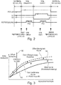
- FIG. 2 clarifies the time course of the measuring process described above.
- FIG. 3 illustrates the calculation for the compensation of the cross-sensitivity of the first sensor 22 based on the measurement results of the second sensor 24th
- a class boundary 52 divides the curve into an offset correction region and a gain correction region.
- other algorithms are also possible to modify offset and gain or even the exponential characteristic.
- the current measured value of the second sensor is used as a reference variable for a statistical probability calculation of all previously determined calibration points or measured values. The most unlikely measured values are then removed from the collection of the measured values, and with the average of the other measured values that are more probable, a new slope and thus a corrected curve 54 relative to a basic characteristic 53 are determined and the system slope is slowly tracked via a filter.
Landscapes
- Chemical & Material Sciences (AREA)
- Health & Medical Sciences (AREA)
- Life Sciences & Earth Sciences (AREA)
- Engineering & Computer Science (AREA)
- General Physics & Mathematics (AREA)
- Pathology (AREA)
- Immunology (AREA)
- Physics & Mathematics (AREA)
- Analytical Chemistry (AREA)
- Biochemistry (AREA)
- General Health & Medical Sciences (AREA)
- Food Science & Technology (AREA)
- Medicinal Chemistry (AREA)
- Combustion & Propulsion (AREA)
- Investigating Or Analyzing Materials By The Use Of Electric Means (AREA)
- Chemical Kinetics & Catalysis (AREA)
- Electrochemistry (AREA)
- Other Investigation Or Analysis Of Materials By Electrical Means (AREA)
- Molecular Biology (AREA)
- Toxicology (AREA)
- Investigating Or Analyzing Materials By The Use Of Fluid Adsorption Or Reactions (AREA)
Description
Die vorliegende Erfindung betrifft ein Messgerät und ein Verfahren zur Erfassung des Kohlenwasserstoffanteils in Gasen.The present invention relates to a measuring device and a method for detecting the hydrocarbon content in gases.
Derartige Messgeräte sind mit verschiedenen Sensortechnologien bekannt und dienen der Erfassung des Gehaltes von Öl, Kohlenwasserstoffen und oxidierbaren Gasen beispielsweise in Luft oder Druckluft.Such meters are known with various sensor technologies and serve to detect the content of oil, hydrocarbons and oxidizable gases, for example in air or compressed air.
Häufig werden beispielsweise elektrisch beheizbare Metalloxid-Halbleitergassensoren mit Halbleiter-Oxidmaterialien verwendet, die im beheizten Zustand ihren elektrischen Widerstand in Abhängigkeit von der Menge der in der Luft enthaltenen Kohlenwasserstoffe verändern. Die wichtigsten Vorteile von Metalloxyd-Halbleitergassensoren sind die sehr hohe Empfindlichkeit und damit die Möglichkeit auch geringste Kohlenwasserstoffanteile bis in den ppt-Bereich messen zu können. Sie weisen eine sehr lange Standzeit, eine sehr gute Langzeitstabilität auf und die Anschaffungskosten sind eher gering.Frequently, for example, electrically heatable metal oxide semiconductor gas sensors are used with semiconductor oxide materials that change their electrical resistance in the heated state in dependence on the amount of hydrocarbons contained in the air. The most important advantages of metal oxide semiconductor gas sensors are the very high sensitivity and thus the ability to measure even the smallest hydrocarbon fractions down to the ppt range. They have a very long life, a very good long-term stability and the initial cost is rather low.
Nachteilig bei Metalloxyd-Halbleitergassensoren ist allerdings, dass sie eine exponentielle Kennlinie aufweisen, wodurch sich ihr Offset-Punkt schwer bestimmen lässt. Die Messergebnisse sind relativ schlecht reproduzierbar und die Sensoren weisen hohe Querempfindlichkeiten gegen Wasserdampf und anorganische Gase auf. Die Einstellzeiten bis zum endgültigen Wert sind hoch und die Erholungszeiten bei einer Kalibrierung mit Nullluft bis zum Erreichen der Nulllinie sind relativ lang.A disadvantage of metal oxide semiconductor gas sensors, however, is that they have an exponential characteristic, which makes it difficult to determine their offset point. The measurement results are relatively poorly reproducible and the sensors have high cross sensitivities to water vapor and inorganic gases. The setup times up to the final value are high and the recovery times for zero air calibration until reaching the zero line are relatively long.
Eine weitere Methode ist die Erfassung der Kohlenwasserstoffkonzentration mittels Photoionisation. Dabei werden die Kohlenwasserstoffe mit ultraviolettem Licht bestrahlt. Die Energiemenge des Lichts muss dabei so hoch sein, dass Elektronen aus dem Kohlenwasserstoffmolekül herausgetrieben werden. Deren Anzahl lässt sich elektronisch messen. Photoionisationssensoren weisen eine gute Langzeitstabilität, eine relativ geringe Querempfindlichkeit gegen Wasserdampf und anorganische Gase auf. Die Einstellzeiten bis zum endgültigen Wert sind kurz, ebenso die Erholzeiten bei einer Kalibrierung mit Nullluft, bis die Nulllinie erreicht wird. Die Kennlinie ist linear, wodurch eine hohe Reproduzierbarkeit gegeben ist.
Nachteilig bei derartigen Sensoren ist jedoch deren geringe Empfindlichkeit, was insbesondere im gering konzentrierten Bereich relevant ist. Ohne Prüfgas lässt sich auch der Alterungszustand nicht sicher bestimmen, die Standzeit ist aber ohnehin mit etwa einem Jahr eher gering. Durch Verschleiß nimmt die Messgenauigkeit ab, weswegen auch die Wartungskosten hoch sind. Weiterhin sind auch die Anschaffungskosten von Photoionisationssensoren relativ hoch.Another method is the detection of the hydrocarbon concentration by means of photoionization. The hydrocarbons are irradiated with ultraviolet light. The amount of energy of the light must be so high that electrons are driven out of the hydrocarbon molecule. Their number can be measured electronically. Photoionization sensors have a good long-term stability, a relatively low cross-sensitivity to water vapor and inorganic gases. The setup times to the final value are short, as well as the recovery times for zero air calibration until the zero line is reached. The characteristic curve is linear, whereby a high reproducibility is given.
A disadvantage of such sensors, however, is their low sensitivity, which is particularly relevant in the low concentration range. Without test gas, the state of aging can not be determined with certainty, but the service life is rather low at about one year anyway. Due to wear, the measuring accuracy decreases, which is why the maintenance costs are high. Furthermore, the cost of Photoionisationssensoren are relatively high.
Die mittels Photoionisationssensoren generierten Messwerte lassen nur indirekt auf die gemessene Stoffmenge schließen, da die Messwerte auch vom molekularen Aufbau der Verbindung abhängig sind und selbst bei gleichen Summenformeln recht stark variieren. Sofern die zu messende Verbindung aber konstant, bekannt und möglichst auch einheitlich ist, lässt sich die Konzentration des Kohlenwasserstoffanteils relativ zuverlässig messen. Allerdings sinkt die Messgenauigkeit mit abnehmender Konzentration an Kohlenwasserstoffen. Insbesondere steigt dabei der Einfluss des Feuchtegehalts der Luft. Mit abnehmendem Kohlenwasserstoffanteil wird der Einfluss der Luftfeuchte zunehmend größer, Messungen von Kohlenwasserstoffanteilen im unteren mg/m3-Bereich und insbesondere im µg/-m3-Bereich sind nicht ausreichend genau durchzuführen.The measured values generated by means of photoionization sensors only indirectly indicate the measured amount of substance, since the measured values also depend on the molecular structure of the compound and vary quite widely even with the same sum formulas. However, if the compound to be measured is constant, known and, if possible, uniform, the concentration of the hydrocarbon fraction can be measured relatively reliably. However, the measurement accuracy decreases with decreasing concentration of hydrocarbons. In particular, the influence of the moisture content of the air increases. With decreasing proportion of hydrocarbons, the influence of air humidity is increasingly greater, measurements of hydrocarbon fractions in the lower mg / m 3 range and especially in the μg / m 3 range are not sufficiently accurate.
Für die unterschiedlichen Anwendungen von Druckluft werden unterschiedliche Grenzwerte für den Ölanteil gefordert. Ölanteile bestehen aus tröpfchenförmigen Ölerosolen und aus Öldämpfen. Ölerosole und Öldämpfe können durch verschiedene Verfahren aus dem Druckluftstrom teilweise oder weitgehend eliminiert werden.For the different applications of compressed air different limits for the oil content are required. Oil components consist of droplet-shaped oil aerosols and oil vapors. Oil aerosols and oil vapors can be partially or substantially eliminated from the compressed air stream by various methods.
Die Aufgabe der Erfindung besteht darin, ein Messgerät zur Erfassung des Gehalts von Öl, Kohlenwasserstoffen und oxidierbaren Gasen in Gasen zu schaffen, dass auch geringste dauerhaft Konzentrationen zuverlässig misst. Mögliche Messfehler sollen leicht zu ermitteln und korrigierbar sein. Weiterhin ist es Aufgabe der Erfindung ein gegenüber dem Stand der Technik verbessertes Verfahren zur Erfassung des Gehaltes von Öl, Kohlenwasserstoffanteilen und oxidierbaren Gasen in Gasen bereit zu stellen.The object of the invention is to provide a measuring device for detecting the content of oil, hydrocarbons and oxidizable gases in gases that reliably measures even the lowest permanent concentrations. Possible measurement errors should be easy to determine and correct. It is another object of the invention to provide a comparison with the prior art improved method for detecting the content of oil, hydrocarbon fractions and oxidizable gases in gases.
Die Aufgabe wird gelöst, durch Messgerät zur Erfassung von Kohlenwasserstoffanteilen in Gasen, aufweisend
- einen ersten Sensor zur Bestimmung des Anteils an Kohlenwasserstoff in einem Messgasstrom und zur Erzeugung eines entsprechenden ersten Messergebnisses,
- einen zweiten Sensor zur Bestimmung des Anteils an Kohlenwasserstoff im Messgasstrom und zur Erzeugung eines entsprechenden zweiten Messergebnisses,
- eine Auswerteinheit zur Auswertung der Messergebnisse der beiden Sensoren
- eine Katalysatoreinheit (34) zur Erzeugung eines Katalysatorgasstroms (36)
wobei - der erste Sensor als Metalloxid-Halbleitergassensor ausgeführt ist und kontinuierlich Messungen durchführt,
- der zweite Sensor als Photoionisationssensor ausgeführt ist und diskontinuierlich Messungen durchführt.
- der Katalysatorgasstrom (36) dem zweiten Sensor (24) zuführbar ist.
- a first sensor for determining the proportion of hydrocarbon in a sample gas stream and for generating a corresponding first measurement result,
- a second sensor for determining the proportion of hydrocarbon in the measurement gas flow and for generating a corresponding second measurement result,
- an evaluation unit for the evaluation of the measurement results of the two sensors
- a catalyst unit (34) for generating a catalyst gas stream (36)
in which - the first sensor is designed as a metal oxide semiconductor gas sensor and carries out measurements continuously,
- the second sensor is designed as a photoionization sensor and performs discontinuous measurements.
- the catalyst gas stream (36) can be fed to the second sensor (24).
Weiterhin wird die Aufgabe durch ein Verfahren zum Erfassen des Kohlenwasserstoffanteils in einem Gasstrom gelöst, das gekennzeichnet ist durch die Verfahrensschritte:
- kontinuierliches Zuleiten eines Messgasstroms an einen ersten Sensor, der als Metalloxid-Halbleitergassensor ausgeführt ist,
- Bestimmen des Anteils an Kohlenwasserstoff im Messgasstrom und Erzeugen eines ersten Messergebnisses durch den ersten Sensor,
- diskontinuierliches Zuleiten des Messgasstrom an einen zweiten Sensor (24), der als Photoionisationssensor ausgeführt ist,
- Bestimmen des Anteils an Kohlenwasserstoff im Messgasstrom und Erzeugen eines zweiten Messergebnisses durch den zweiten Sensor,
- Auswerten der Messergebnisse der beiden Sensoren,
- Erzeugen eines Katalysatorgasstroms (36), wobei dem zweiten Sensor (24) dann der Katalysatorgasstrom (36) zugeführt wird, wenn der zweite Sensor (24) abgeschaltet oder unbenutzt ist.
- continuous supply of a sample gas stream to a first sensor, which is designed as a metal oxide semiconductor gas sensor,
- Determining the proportion of hydrocarbon in the sample gas stream and generating a first measurement result by the first sensor,
- discontinuously supplying the sample gas stream to a second sensor (24), which is designed as a photoionization sensor,
- Determining the proportion of hydrocarbon in the sample gas stream and generating a second measurement result by the second sensor,
- Evaluation of the measurement results of the two sensors,
- Generating a catalyst gas stream (36), wherein the catalyst gas stream (36) is then supplied to the second sensor (24) when the second sensor (24) is turned off or unused.
Das erfindungsgemäße Messgerät kombiniert erstmals die beiden unterschiedlichen Sensoren, die sich üblicherweise in einem Messgerät eher ausschließen. Es wurde bisher überflüssig angesehen, beide Sensoren in nur einem Messgerät zu verwenden.For the first time, the measuring device according to the invention combines the two different sensors, which usually preclude one another in a measuring device. It was previously considered superfluous to use both sensors in a single meter.
Der Metalloxid-Halbleitergassensor, kurz MOX-Sensor, bietet als Vorteil gegenüber dem Photoionisationssensor, kurz PID-Sensor, die lange Lebenserwartung ohne Wartung bei geringen Anschaffungskosten. Für ein Öldampf-Messgerät lassen sich theoretisch mehrere Jahre Einsatz ohne Wartung und Rekalibrierung realisieren.The metal oxide semiconductor gas sensor, MOX sensor for short, offers the advantage over the photoionization sensor, short PID sensor, the long life expectancy without maintenance at low acquisition cost. For an oil vapor meter, theoretically several years of use can be achieved without maintenance and recalibration.
Der PID-Sensor ist bezüglich Querempfindlichkeit, Reproduzierbarkeit und Langzeitstabilität der genauere Sensor, er ermöglicht präzisere Messungen und weist eine geringere Querempfindlichkeit auf.The PID sensor is the most accurate sensor in terms of cross sensitivity, reproducibility and long-term stability, allowing more accurate measurements and less cross-sensitivity.
Ein wesentlicher Aspekt der Erfindung besteht darin, dass die beiden Sensoren unterschiedlich genutzt werden. Der MOX-Sensor ist dauerhaft in Betrieb und führt kontinuierlich Messungen durch. Der PID-Sensor dagegen misst nur in zyklischen Intervallen, zum Beispiel einmal täglich, zusätzlich und parallel zum MOX-Sensor. Die ermittelten Messwerte des PID-Sensors dienen dann dazu, beispielsweise eine Steigung oder den Offset des MOX-Sensors zu korrigieren. Die Messung des PID-Sensors erfolgt dabei unmittelbar nach einer zuvor vorzugsweise automatisch durchgeführten Nullluft-Kalibrierung.An essential aspect of the invention is that the two sensors are used differently. The MOX sensor is permanently in operation and continuously performs measurements. In contrast, the PID sensor only measures in cyclic intervals, for example once a day, in addition to and parallel to the MOX sensor. The determined measured values of the PID sensor then serve to correct, for example, a slope or the offset of the MOX sensor. The measurement of the PID sensor takes place immediately after a previously preferably automatically carried out zero-air calibration.
Durch die diskontinuierliche Zuschaltung des PID-Sensors wird eine wesentlich längere Standzeit dieses ansonsten eher kurzlebigen Sensors erreicht.Due to the discontinuous connection of the PID sensor, a significantly longer service life of this otherwise rather short-lived sensor is achieved.
Beide Sensoren weisen eine relativ hohe Querempfindlichkeit gegen Wasser auf. Bei MOX-Sensoren führt diese Querempfindlichkeit zu einer Verschiebung des Arbeitspunkts auf dessen exponentiellen Kennlinie und damit zu einem Offset- und/oder Gainfehler.Both sensors have a relatively high cross-sensitivity to water. For MOX sensors, this cross-sensitivity leads to a shift of the operating point to its exponential characteristic and thus to an offset and / or gain error.
Beim PID-Sensor sind dagegen zwei Effekte bekannt, einmal der sogenannte Water-Quenching Effekt, der zu einem Steigungsfehler führt. Außerdem kann es zu Leckströmen aufgrund von Anlagerungen oder Verschmutzungen am Elektroden-Stack kommen, die zu einem feuchteabhängigen Offset-Fehler führen. Erfindungsgemäß kann deshalb am Gaseintritt des Messgeräts ein Trocknungselement, beispielsweise eine Membrane vorgesehen, welche den Wassergehalt signifikant reduziert. Hierfür können bekannte Membrantrockner verwendet werden, die die Luft selbst trocknen und expandierte Spülluft für den Trocknungsprozess nutzen. Auch die Nutzung von Adsorptionstrocknern ist möglich.In the PID sensor, however, two effects are known, the so-called water-quenching effect, which leads to a slope error. In addition, leakage currents may occur due to buildup or contamination on the electrode stack, resulting in a moisture-dependent offset error. According to the invention Therefore, a drying element, for example a membrane, which significantly reduces the water content can be provided at the gas inlet of the measuring device. For this purpose, known membrane dryer can be used, which dry the air itself and use expanded purge air for the drying process. The use of adsorption dryers is possible.
Der Einsatz eines Trocknungselements im Ursprungsgasstrom (Messgasstrom), beispielsweise eines Membrantrockners weist sowohl Vorteile für die Nutzung des PID-Sensors als auch für die Nutzung des MOX-Sensors auf, was weiterhin vorteilhaft gegenüber dem Stand ist, der diese beiden Sensortypen üblicherweise nicht kombiniert.The use of a drying element in the source gas stream (sample gas stream), for example a membrane dryer has both advantages for the use of the PID sensor as well as for the use of the MOX sensor, which is also advantageous over the state that usually does not combine these two sensor types.
Grundsätzlich ist auch die Verwendung eines Adsorbtionstrockners möglich. Wesentlich ist, dass das Trocknungselement eine hohe Trocknungsleistung aufweist, die durch Adsorbtionstrockner oftmals nicht ausreichend gewährleistet ist.In principle, the use of a Adsorbtionstrockners is possible. It is essential that the drying element has a high drying performance, which is often not sufficiently ensured by Adsorbtionstrockner.
Erfindungsgemäß ist darüber hinaus eine Katalysatoreinheit vorgesehen, die eine Offset-Stabilisierung des PID-Sensors mit Nullluft ermöglicht. Der PID-Sensor wird erfindungsgemäß immer dann mit einem Katalysatorgasstrom (katalysiertes Messgas) gespült, wenn er unbenutzt und abgeschaltet ist. Damit wird der PID-Sensors stets sauber gehalten und die Stabilität und Nutzungsdauer wird erhöht. Erst unmittelbar bevor der PID-Sensor parallel zum MOX-Sensor betrieben wird, wird der PID-Sensor unter Spannung gesetzt und dessen Lampe eingeschaltet. Nach ausreichender Stabilisierungszeit erfolgt ein automatischer Nullabgleich. Nach diesem Abgleich wird der Ursprungsgasstrom in einen ersten und zweiten Messgasstrom aufgeteilt, und dem PID-Sensor der zweite Messgasstrom zugeleitet. Der PID-Sensor vermisst diesen zweiten Messgasstrom dann parallel zum MOX-Sensor, der den ersten Messgasstrom vermisst.Moreover, according to the invention, a catalyst unit is provided which enables offset stabilization of the PID sensor with zero air. According to the invention, the PID sensor is always purged with a catalyst gas stream (catalyzed sample gas) when it is unused and switched off. This keeps the PID sensor clean at all times and increases stability and service life. Immediately before the PID sensor is operated parallel to the MOX sensor, the PID sensor is energized and its lamp is switched on. After a sufficient stabilization time, an automatic zero adjustment takes place. After this adjustment, the original gas stream is split into a first and second sample gas stream, and the second sample gas stream is fed to the PID sensor. The PID sensor then measures this second sample gas flow parallel to the MOX sensor, which measures the first sample gas flow.
Mit dem Messergebnis des PID-Sensors ist es möglich, den Offset des MOX-Sensors oder auch den Gain-Fehler des MOX-Sensors auszugleichen bzw. den MOX-Sensor zu kalibrieren.With the measurement result of the PID sensor, it is possible to compensate for the offset of the MOX sensor or even the gain error of the MOX sensor or to calibrate the MOX sensor.
Die Nutzung der Katalysatoreinheit erlaubt nicht nur eine reine Offset-Stabilisierung des PID-Sensors, sondern erfindungsgemäß auch die Kompensation der Querempfindlichkeit des MOX-Sensors und die Bestimmung des Offset-Punktes des MOX-Sensors auf seiner Kennlinie.The use of the catalyst unit not only allows a pure offset stabilization of the PID sensor, but according to the invention also the compensation the cross-sensitivity of the MOX sensor and the determination of the offset point of the MOX sensor on its characteristic.
Die Kompensation der Querempfindlichkeit des MOX-Sensors mit Hilfe des PID-Sensors basiert auf den unterschiedlichen Arbeitsweisen der Sensoren. Der MOX-Sensor besitzt eine exponentielle Kennlinie, die bei der Herstellung des Sensors kalibriert wird und im Gerät hinterlegt ist. Der PID-Sensor dagegen arbeitet nahezu linear und wird mit Nullluft kalibriert. Der PID-Sensor kann somit den Nullwert bei einem Messvorgang um Klasse 1(ISO 8573: Öldampfanteile unter 0,01mg je m3 Gas) sehr genau messen.Compensation of the cross sensitivity of the MOX sensor using the PID sensor is based on the different modes of operation of the sensors. The MOX sensor has an exponential characteristic, which is calibrated during manufacture of the sensor and stored in the device. In contrast, the PID sensor works almost linearly and is calibrated with zero air. The PID sensor can thus very accurately measure the zero value during a measurement procedure of class 1 (ISO 8573: oil vapor fractions below 0.01 mg per m 3 gas).
Die Kompensation der Querempfindlichkeit des MOX wird durchgeführt, indem kalibrierte Punkte der Messwerte des PID-Sensors (auch die früher gemessenen Punkte) auf der exponentiellen Kurve des MOX-Sensors abgebildet werden, sofern die Messwerte schlechter als Klasse 1 sind. Der aktuelle Messwert des PID-Sensors wird dabei als Führungsgröße für eine statistische Wahrscheinlichkeitsberechnung aller zuvor bestimmten Kalibrierpunkte benutzt, die unwahrscheinlichen Punkte werden aus der Sammlung der Messwerte entfernt. Mit dem Mittelwert aller übrigen, also wahrscheinlichen Kalibrierpunkte wird die neue Steigung bestimmt und über ein Filter die Systemsteigung langsam nachgeführt.Cross-sensitivity compensation of the MOX is performed by plotting calibrated points of the PID sensor readings (including the previously measured points) on the exponential curve of the MOX sensor if the readings are worse than Class 1. The current measured value of the PID sensor is used as a reference variable for a statistical probability calculation of all previously determined calibration points, the unlikely points are removed from the collection of the measured values. With the mean of all other, so probable calibration points, the new slope is determined and slowly tracked through a filter, the system slope.
Bei Messwerten besser als Klasse 1 wird hingegen der Offsetwert korrigiert, und der Arbeitspunkt auf der exponentiellen Kennlinie des MOX-Sensors für den Offsetwert bestimmt. Durch einen mathematischen Algorithmus ist es möglich, auch mit dem MOX-Sensor, der für Messung in Klasse 1 eigentlich eine viel zu hohe Querempfindlichkeit besitzt, bis hinunter zu Klasse 1 und besser zu messen.For measured values better than class 1, on the other hand, the offset value is corrected and the operating point on the exponential curve of the MOX sensor is determined for the offset value. A mathematical algorithm makes it possible to measure even down to class 1 and better with the MOX sensor, which is actually much too cross-sensitive for Class 1 measurements.
Das Messgerät weist eine Auswerteinheit zur Auswertung der Messergebnisse auf. In einer ersten Ausführungsvariante können die beiden Sensoren mit einer einzigen Auswerteeinheit verbunden sein, denkbar ist aber auch, dass jedem Sensor eine eigene Auswerteeinheit zugeordnet ist. Die Auswerteeinheit weist einen Prozessor auf, der die notwendigen Berechnungen durchführt. Es können die einzelnen Gasströme oder die Summe aller Gasströme durch den Sensor bzw. die Sensoren gemessen oder von der Auswerteeinheit ausgewertet werden.The measuring device has an evaluation unit for evaluating the measurement results. In a first embodiment, the two sensors can be connected to a single evaluation unit, but it is also conceivable that each sensor is assigned its own evaluation unit. The evaluation unit has a processor which performs the necessary calculations. The individual gas flows or the sum of all gas flows can be measured by the sensor or the sensors or evaluated by the evaluation unit.
Weiterhin ist eine Anzeigeeinheit vorgesehen, die die Messergebnisse der Sensoren oder von der Auswerteeinheit berechnete Werte und/oder weitere Informationen anzeigt. Die Anzeigeeinheit kann vorteilhafterweise auch als Eingabeeinheit in Form eines Touchscreens ausgeführt sein.Furthermore, a display unit is provided which displays the measurement results of the sensors or values calculated by the evaluation unit and / or further information. The display unit may advantageously also be designed as an input unit in the form of a touchscreen.
Durch die Nutzung der beiden Sensoren wird auch erreicht, dass das Messgerät auch dann im Notbetrieb weiterbetrieben werden kann, wenn einer der beiden Sensoren ausfällt. Die Auswerteeinheit ist auch in der Lage, einen der beiden fehlerhaften Sensoren oder Gaswege selbstständig abzuschalten, so dass das Messgerät weiterhin einsatzbereit bleibt. Vorteilhafterweise gibt die Auswerteeinheit eine entsprechende Information über die Anzeigeeinheit aus, so dass das Messgerät vor Ausfall des zweiten Gasweges oder Sensors und dem damit verbundenen Gesamtausfall repariert werden kann. Ein wesentlicher Vorteil ergibt sich auch daraus, dass somit die entsprechende Reparatur zur Not während einer späteren ohnehin anstehenden Betriebspause durchführbar ist.The use of the two sensors also ensures that the measuring device can continue to be operated in emergency mode even if one of the two sensors fails. The evaluation unit is also able to automatically switch off one of the two faulty sensors or gas paths, so that the measuring device remains ready for use. Advantageously, the evaluation unit outputs a corresponding information about the display unit, so that the measuring device can be repaired before failure of the second gas path or sensor and the associated total failure. A significant advantage also results from the fact that thus the corresponding repair for emergencies during a later pending downtime is feasible.
Letztendlich ist das Messgerät mit einem entsprechenden Fehleranalyseprogramm in der Lage, sämtliche Bauteile im Gasweg selbstständig zu überprüfen. Auch ein Spülen der Sensoren mit Referenzgas kann in regelmäßigen Zyklen oder aufgrund eines abweichenden oder auffälligen Messergebnisses vom Messgerät selbstständig eingeleitet werden.Ultimately, the measuring device with a corresponding error analysis program is able to independently check all components in the gas path. Rinsing of the sensors with reference gas can also be initiated automatically by the measuring instrument in regular cycles or due to a deviating or conspicuous measurement result.
Das erfindungsgemäße Messgerät kann weiterhin derart ausgeführt sein, dass beide Sensoren jeweils mit einem Referenzgasstrom, beispielsweise aus einer Vorratsflasche, beaufschlagt werden können. Neben dem unveränderten Messgas und dem katalysierten Messgas wird also weiterhin regelmäßig ein Referenzgasstrom, beispielsweise zur Neufestlegung der vom Sensor ausgehenden Signalstärke verwendet. Das Kalibriergas (z.B. Isobuten) weist einen definierten Kohlenwasserstoffanteil auf, allerdings keine oder nur eine ausgesprochen geringe Feuchtigkeit. Erfindungsgemäß ist es somit möglich, die Veränderung der Signalstärke und Messempfindlichkeit durch Alterung und Verschmutzung des Messgeräts zuverlässig auszugleichen. Die Kalibriermessung kann in regelmäßigen Abständen automatisch erfolgen, sie kann aber auch jederzeit vom Anwender eingeleitet werden. Insbesondere kann sie im Rahmen der Fehleranalyse vom Fehleranalyseprogramm genutzt werden. Die im Rahmen der Kalibriermessung ermittelten Daten werden gespeichert und können jederzeit abgerufen und von der Auswerteinheit genutzt werden.The measuring device according to the invention can furthermore be embodied such that both sensors can in each case be charged with a reference gas stream, for example from a storage bottle. In addition to the unchanged measurement gas and the catalyzed sample gas, therefore, a reference gas stream is also regularly used, for example for redetermining the signal strength emanating from the sensor. The calibration gas (eg isobutene) has a defined hydrocarbon content, but no or only a very low level of moisture. According to the invention, it is thus possible to reliably compensate for the change in signal strength and measuring sensitivity due to aging and soiling of the measuring device. The calibration measurement can be done automatically at regular intervals, but it can also be initiated by the user at any time. In particular, it can be used within the framework of the error analysis by the error analysis program. The values determined during the calibration measurement Data is stored and can be retrieved at any time and used by the evaluation unit.
Erfindungsgemäß können der PID-Sensor und der MOX-Sensor zur Gain-Kalibrierung gleichzeitig mit Referenzgas beaufschlagt werden. Diese Funktionalität kann zum einen für eine zyklische Autokalibrierung des Geräts genutzt werden, als auch für eine Rekalibrierung im Rahmen eines Service. Das Referenzgas hat typischerweise eine Konzentration im oberen Messbereich, z.B. 500 ppb. Nach Beginn der Zuleitung des Referenzgases zu den beiden Sensoren wird der Gain-Wert beider Sensoren nach einer angemessenen Stabilisierungszeit kalibriert.According to the invention, the PID sensor and the MOX sensor for gain calibration can be acted upon simultaneously with reference gas. This functionality can be used for a cyclic auto-calibration of the device as well as for a recalibration within the scope of a service. The reference gas typically has a concentration in the upper measurement range, e.g. 500 ppb. After starting the supply of the reference gas to the two sensors, the gain value of both sensors is calibrated after a reasonable stabilization time.
Bei der parallelen Zuleitung des Referenzgases an beide Sensoren kann während der Gain-Kalibrierung keine Messung von Kohlenwasserstoffanteilen erfolgen. Erfindungsgemäß kann aber für beide Sensoren ein separates Ventil vorgesehen sein, das die Zuleitung zu nur einem der beiden Sensoren zulässt, wodurch die die Gain Kalibrierung separat durchgeführt und der jeweils andere Sensor für die kontinuierliche Messung weiter benutzt werden kann.With the parallel supply of the reference gas to both sensors, no measurement of hydrocarbon fractions can take place during the gain calibration. According to the invention, however, a separate valve can be provided for both sensors, which allows the supply line to only one of the two sensors, whereby the gain calibration can be carried out separately and the respective other sensor can be used for the continuous measurement.
Das Messgerät kann dann besonders kostengünstig hergestellt werden, wenn technische Einheiten in Form von Baublöcken zusammengefasst werden. Dies kann beispielsweise Ventile, Drosseln, Katalysatoren und Sensoren betreffen. Die entsprechenden Elemente und Bauteile bestehen beispielsweise aus Metall.The measuring device can then be produced in a particularly cost-effective manner if technical units are combined in the form of building blocks. This may concern, for example, valves, throttles, catalysts and sensors. The corresponding elements and components are made of metal, for example.
Der PID-Sensor weist eine Sensoreinheit mit Probenahmesonde auf, vorzugsweise nutzen beide Sensoren gemeinsam eine Probenahmesonde. Die Sensoreinheit ist dabei über ein Signalkabel oder kabellos mit der Auswerteeinheit verbunden. Die Probenahmesonde kann vorzugsweise von oben zentrisch in eine Steigleitung montiert sein, so dass sie mittig aus dem zu überwachenden Gasstrom Gas entnehmen kann. Die Sensoreinheit weist definierte Fließwiderstände auf, die für einen konstanten Druck und einen konstanten Volumenstrom der einzelnen Messgase sorgen und beispielsweise durch eine Drossel mit definierter Bohrung, bzw. aus einem Sintermetall gebildet sind. Diese sind besonders wartungsarm und einfach zu reinigen. Weiterhin ist eine Alarmfunktion vorgesehen, die dem Benutzer bei zu niedrigem oder zu hohem Druck der Gasströme visuell oder akustisch informiert.The PID sensor has a sensor unit with sampling probe, preferably both sensors share a sampling probe. The sensor unit is connected via a signal cable or wirelessly to the evaluation unit. The sampling probe can preferably be mounted centrally from above in a riser, so that it can remove gas centrally from the gas stream to be monitored. The sensor unit has defined flow resistances, which ensure a constant pressure and a constant volume flow of the individual measuring gases and are formed, for example, by a throttle with a defined bore or of a sintered metal. These are very low maintenance and easy to clean. Furthermore, an alarm function is provided which informs the user visually or acoustically if the gas flows are too low or too high.
Die Durchflussmenge der verschiedenen Gasströme kann mit entsprechenden Drosseln, Ventilen oder Durchflussreduktoren beeinflusst werden. Diese sind vorzugsweise austauschbar und in einer besonders vorteilhaften Ausführungsvariante regelbar, um damit zum Einen die Durchflussmenge zu den Sensoren einstellen und zum Anderen die gewünschten Mischverhältnisse der zu mischenden Gasströme zuverlässig gewährleisten zu können.The flow rate of the various gas streams can be influenced by appropriate throttles, valves or flow rate reducers. These are preferably interchangeable and can be regulated in a particularly advantageous embodiment in order to be able to adjust the flow rate to the sensors on the one hand and reliably ensure the desired mixing ratios of the gas flows to be mixed on the other hand.
Dadurch, dass die Ventile im Gasweg einzeln schaltbar sind, ist auch möglich, Referenzluft und Messluft gleichzeitig auf den Sensor zu schalten und das Messgas zu verdünnen. Damit kann der Messbereich nach oben erweitert werden, wenn die Messluft extrem stark verschmutzt ist.Because the valves in the gas path can be individually switched, it is also possible to switch reference air and measuring air simultaneously to the sensor and to dilute the sample gas. Thus, the measuring range can be extended upward if the measuring air is extremely heavily polluted.
Als Katalysatorgaseinheiten können übliche Oxidationskatalysatoren eingesetzt werden, denkbar sind aber auch andere Vorrichtungen oder Verfahren zur Bereitstellung von Gasen mit den gewünschten Eigenschaften. Als Oxidationskatalysator dient beispielsweise platinierte Quarzwolle, die problemlos in einen dafür vorgesehenen Behälter einführbar ist. Denkbar ist auch die Nutzung von Aktivkohle. In einer besonders vorteilhaften Variante ist der Referenzgaserzeuger in das Messgerät integriert, wodurch vor Ort lediglich die verschiedenen Fluid bzw. Gaszuführungen angeschlossen werden müssen.Conventional oxidation catalysts can be used as catalyst gas units, but other devices or processes for providing gases having the desired properties are also conceivable. The oxidation catalyst used is, for example, platinum-plated quartz wool, which can easily be introduced into a container provided for this purpose. The use of activated carbon is also conceivable. In a particularly advantageous variant of the reference gas generator is integrated into the meter, which on site only the different fluid or gas supplies must be connected.
Das Messgerät weist somit sämtliche Anschlüsse für entsprechende Gasleitungen und auch den elektrischen Anschluss auf, sodass es vor Ort flexibel an beliebigen Orten installierbar ist. Insbesondere die erfindungsgemäße Aufteilung des Messgeräts in die Sensoreinheit mit Sensoren, beispielsweise der Probenahmesonde im Falle des Prinzips der Photoionisation und die Auswerteeinheit mit Bedienoberfläche (Display) erweitert die Möglichkeiten einer räumlich flexiblen Aufstellung vor Ort zusätzlich. Die Auswerteeinheit mit Bedienoberfläche baut klein und kann nahezu überall, vorteilhafterweise an einer gut zugänglichen Position installiert werden, während die etwas größere Sensoreinheit räumlich getrennt von der Auswerteeinheit an der Messgasentnahmestelle angeordnet sein kann. Aber auch die Kombination beider Komponenten ist denkbar und bringt Vorteile. Das Gerät ist dann kompakt und preisgünstig und da der Öldampf in der Gasphase vorliegt kann auch ein Schlauch oder Rohr zur Zuleitung verwendet werden. Außerdem ist die kombinierte Einheit für Wartung einfacher zugänglich.The meter thus has all the connections for corresponding gas lines and also the electrical connection, so that it can be flexibly installed on site anywhere. In particular, the inventive division of the measuring device into the sensor unit with sensors, such as the sampling probe in the case of the principle of photoionization and the evaluation unit with user interface (display) further expands the possibilities of a spatially flexible installation on site. The evaluation with user interface is small and can be installed almost anywhere, advantageously in an easily accessible position, while the slightly larger sensor unit can be arranged spatially separated from the evaluation at the sample gas sampling. But the combination of both components is conceivable and brings advantages. The device is then compact and inexpensive and since the oil vapor is in the gas phase, a hose or pipe can be used for supply. In addition, the combined unit is easier to access for maintenance.
Das erfindungsgemäße Messgerät kann vorzugsweise mit einem ölfrei verdichtenden Kompressor zur Herstellung von Druckluft oder Druckgas verwendet werden, denkbar ist aber auch die Verwendung mit einem ölgeschmierten Kompressor, wenn diesem ein entsprechender Katalysator nachgeschaltet ist. Für Wartungsarbeiten ist vorzugsweise ein Bypass vorgesehen. Grundsätzlich ist das Messgerät aber auch für weitere Verwendungsbereiche geeignet, beispielsweise für Druckgasflaschen.The measuring device according to the invention can preferably be used with an oil-free compressing compressor for the production of compressed air or compressed gas, but is also conceivable use with an oil-lubricated compressor, if this is followed by a corresponding catalyst. For maintenance, a bypass is preferably provided. In principle, however, the measuring device is also suitable for other areas of use, for example for compressed gas cylinders.
Die Erfindung wird im Folgenden mit Bezug auf die beiliegenden Figuren näher erläutert. Dabei zeigen die Figuren lediglich eine vorteilhafte Ausführungsvariante in stark vereinfachter Prinzipdarstellung, die Erfindung soll keinesfalls auf diese beschränkt sein. Es zeigen:
- Fig. 1:
- ein Gaswegschaltschema des Messgeräts,
- Fig. 2:
- ein Messzyklusschema des Messgeräts,
- Fig. 3:
- Kennlinie des MOX-Sensors zur Erläuterung der Kompensation der Querempfindlichkeit
- Fig. 1:
- a gas path diagram of the meter,
- Fig. 2:
- a measuring cycle scheme of the measuring device,
- 3:
- Characteristic curve of the MOX sensor to explain the compensation of the cross sensitivity
Ein Ursprungsgasstrom 26 wird über Gasleitungen und mit Hilfe von Ventilen 27 in einen ersten Messgasstrom 38 und einen zweiten Messgasstrom 39 aufgeteilt.A
Im gezeigten Ausführungsbeispiel ist dem zweiten Sensor 24 eine Katalysatoreinheit 34 vorgeschaltet, die einen Katalysatorgasstrom 36 erzeugt. Analog ist dem ersten Sensor 22 eine zweite Katalysatoreinheit 30 vorgeschaltet, die einen zweiten Katalysatorgasstrom 32 erzeugt.In the embodiment shown, the
Ein Filterelement 40 filtert und ein Trocknungselement 42 trocknet den Ursprungsgasstrom 26 und damit die beiden Messgasströme 38, 39. Das Trocknungselement 42 ist vorzugsweise als Membrantrockner ausgeführt.A
Weiterhin sind ein Druckregler 44 und ein Sicherheitsventil 48 im Ursprungsgasstrom 26 vorgesehen. Drosseln 46, vorzugsweise Expansionsdrosseln sind den Sensoren 22, 24 vorgeschaltet.Furthermore, a
Ein erstes Ventil 27-1 schaltet den zweiten Messgasstrom 39 und ein zweites Ventil 27-2 den Katalysatorgasstrom 36 zum zweiten Sensor 24. Ein drittes Ventil 27-3 schaltet den ersten Messgasstrom 38 und ein viertes Ventil 27-4 den zweiten Katalysatorgasstrom 32 zum ersten Sensor 22.A first valve 27-1 switches the second
Über ein fünftes Ventil 27-5 kann den beiden Sensoren 22, 24 ein Referenzgasstrom 50 zugeleitet werden. Dieser stammt vorzugsweise aus einer extern angeschlossenen Gasflasche, wobei das Gas eine bekannte Konzentration an Kohlenwasserstoffen, beispielsweise im Bereich von 300 - 1000 ppb, vorzugsweise 500 ppb aufweist.Via a fifth valve 27-5, the two
Das Messgerät weist optional einen Schalldämpfer 51 auf.The measuring device optionally has a
Der zweite Sensor 24 kann somit über das erste Ventil 27-1 und über das zweite Ventil 27-2 im Wechsel mit dem zweiten Messgasstrom 39 oder dem Katalysatorgasstrom 36 versorgt werden. Analog kann der erste Sensor 22 über das dritte Ventil 27-3 und das vierte Ventil 27-4 entsprechend mit dem ersten Messgasstrom 38 oder dem zweiten Katalysatorgasstrom 32 versorgt werden. Beiden Sensoren kann über das fünfte Ventil 27-5 ein Referenzgasstrom 50 zugeleitet bekommen.The
Der Ursprungsgasstrom 26 wird über das Filterelement 40 von Partikeln gereinigt und über den Druckregler 44 beispielsweise auf 3,8 bar geregelt. Der Ursprungsgasstrom wird anschließend über das Trocknungselement 42 getrocknet, wobei der Anteil an Kohlenwasserstoff nicht verändert wird. Somit steht am Austritt des Trockenelements ein getrockneter Ursprungsgasstrom 26 mit einem Taupunkt von etwa minus 70° C und einem unveränderten Gehalt an Kohlenwasserstoffen bereit. Beide Sensoren 22, 24 können mit diesem getrockneten Ursprungsgasstrom 26 betrieben werden.The
Während des Betriebs wird der erste Sensor 22, der MOX-Sensor, kontinuierlich mit dem ersten Messgasstrom 38 (also dem getrockneten Ursprungsgasstrom 26), beaufschlagt. Das erste Ventil 27-1 ist geschlossen, das zweite Ventil 27-2 geöffnet, so dass der zweite Sensor 24 dauerhaft mit dem Katalysatorgasstrom 36 gespült wird. Der zweite Sensor 24 ist dabei zunächst ausgeschaltet. Das dritte Ventil 27-3 ist geöffnet, das vierte Ventil 27-4 und das fünfte Ventil 27-5 sind geschlossen.During operation, the
Zur Referenzmessung mit dem zweiten Sensor 24 wird dieser zunächst eingeschaltet. Nach ausreichender Stabilisierungszeit, d.h. konstanter Basislinie, wird dann ohne weiteres Schalten von Ventilen der Offset-Wert des zweiten Sensors 24 aufgenommen. Da das zweite Ventil 27-2 bereits geöffnet war, wurde der zweite Sensor 24 mit dem Katalysatorgasstrom 36, also Nullluft, gespült und ist kohlenwasserstofffrei.For reference measurement with the
Nach der Nullpunkt-Aufnahme schließt das zweite Ventil 27-2 und das erste Ventil 27-1 wird geöffnet. Der zweite Sensor 24, der PID-Sensor, wird nun mit dem zweiten Messgasstrom 39 betrieben und arbeitet parallel zum ersten Sensor 22.After the zero point recording, the second valve 27-2 closes and the first valve 27-1 is opened. The
Nachdem der zweite Sensor 24 Messwerte ermittelt hat, werden folgende Entscheidungen getroffen:
- Liegt der Messwert unter einem bestimmten Wert (der typischerweise Klasse 1 entspricht, ca. 5 ppb), wird über einen Algorithmus der Offset-Punkt des ersten
Sensors 22 korrigiert. Der Algorithmus berücksichtigt die exponentielle Kennlinie des erstenSensors 22.
- If the measured value is below a certain value (which typically corresponds to class 1, approx. 5 ppb), the offset point of the
first sensor 22 is corrected via an algorithm. The algorithm takes into account the exponential characteristic of thefirst sensor 22.
Liegt der Messwert über der Klasse 1, so wird über einen Algorithmus die Steigung der Kennlinie des ersten Sensors 22 korrigiert. Auch dieser Algorithmus berücksichtigt die exponentielle Kennlinie des ersten Sensors.If the measured value is above class 1, the slope of the characteristic of the
Nach dieser Referenzmessung des zweiten Sensors 24 wird dieser wieder auf Nullluft, also den Katalysatorgasstrom 36, geschaltet und die Betriebsspannung abgeschaltet.After this reference measurement of the
Über das vierte Ventil 27-4 kann beim ersten Sensor 22 eine Nullpunkt-Kalibrierung durchgeführt werden. Dazu schließt sich das dritte Ventil 27-3 und öffnet sich das vierte Ventil 27-4. Der erste Sensor 22 wird somit mit dem zweiten Katalysatorgasstrom 32, also Nullluft, beaufschlagt. Nach ausreichender Stabilisierungszeit kann dessen Offset kalibriert werden.About the fourth valve 27-4, a zero point calibration can be performed at the
Über das fünfte Ventil 27-5 können beide Sensoren 22, 24 gleichzeitig mit dem Referenzgasstrom 50 beaufschlagt werden. Dies kann zyklisch im Rahmen einer Autokalibrierung des Gerätes erfolgen, es ist aber auch eine Rekalibrierung im Rahmen einer Servicemaßnahme möglich.Via the fifth valve 27-5, both
Mit Hilfe des Referenzgasstrom 50 kann eine Gain-Kalibrierung durchgeführt werden. Zu diesem Zweck sind die ersten Ventile 27-1 bis 27-4 geschlossen und nur das fünfte Ventil 27-5 geöffnet. Nach angemessener Stabilisierungszeit kann der Gain-Wert beider Sensoren 22, 24 bestimmt werden.With the aid of the
Alternativ kann erfindungsgemäß ein weiteres Ventil vorgesehen sein, das eine getrennte Gain-Kalibrierung der beiden Sensoren 22, 24 ermöglicht.Alternatively, according to the invention, a further valve can be provided, which enables a separate gain calibration of the two
Eine Klassengrenze 52 teilt die Kurve in einen Bereich zur Offset-Korrektur und einen Bereich zur Gain (Steigungs)-Korrektur auf. Neben der Nutzung der Klassengrenze 52 sind auch andere Algorithmen möglich, um Offset- und Gain oder sogar die exponentielle Kennlinie zu modifizieren.A
Sind die vom zweiten Sensor 24 gemessenen Messwerte schlechter als Klasse 1, ist also die Konzentration höher, wird der aktuelle Messwert des zweiten Sensors als Führungsgröße für eine statistische Wahrscheinlichkeitsberechnung aller zuvor bestimmten Kalibrierpunkte oder Messwerte verwendet. Die unwahrscheinlichsten Messwerte werden dann aus der Sammlung der Messwerte entfernt und mit dem Mittelwert der übrigen Messwerte, die wahrscheinlicher sind, wird eine neue Steigung und damit eine gegenüber einer Basiskennlinie 53 korrigierte Kurve 54 bestimmt und über einen Filter die Systemsteigung langsam nachgeführt.If the measured values measured by the
Sind die Messwerte besser als Klasse 1, wird eine Offset-Kalibrierung durchgeführt und der Arbeitspunkt auf der exponentielle Kennlinie des ersten Sensors 22 für den Offsetwert bestimmt. Somit ist es möglich mit dem ersten Sensor 22, der eigentlich eine viel zu hohe Querempfindlichkeit besitzt, bis hinunter zu Klasse 1 zu messen und zuverlässige Messergebnisse zu erhalten.If the measured values are better than class 1, an offset calibration is carried out and the operating point on the exponential curve of the
Die Erfindung ist nicht auf das beschriebene Ausführungsbeispiel beschränkt, dieses dient ausschließlich der Beschreibung und soll nicht einschränkend zu verstehen sein.The invention is not limited to the embodiment described, this is solely for the description and is not intended to be limiting.
Claims (15)
- A measuring device (20) for detecting hydrocarbon contents in gases, comprising- a first sensor (22) for determining the hydrocarbon content in a measuring gas flow (38) and for producing a corresponding first measurement result,- a second sensor (24) for determining the hydrocarbon content in a second measuring gas flow (39) and for producing a corresponding second measurement result,- an evaluation unit for evaluating the measurement results of the two sensors (22, 24),- a catalyst unit (34) for producing a catalyst gas flow (36),wherein- the first sensor (22) is configured as a metal oxide semiconductor gas sensor and continuously carries out measurements,- the second sensor (24) is configured as a photoionization sensor and discontinuously carries out measurements,- the catalyst gas flow (36) can be fed to the second sensor (24).
- The measuring device (20) according to claim 1, characterized in that a second catalyst unit (30) for the generation of a second catalyst gas flow (32), which can be fed to the first sensor (22), is provided.
- The measuring device (20) according to any one of the claims 1 to 2, characterized in that the catalyst gas units (30, 34) are formed by oxidation catalysts.
- The measuring device (20) according to any one of the claims 1 to 3, characterized in that a reference gas flow (50) with a hydrocarbon concentration in the upper measurement range of the two sensors (22, 24) can be fed to the two sensors (22, 24).
- The measuring device (20) according to any one of the claims 1 to 4, characterized in that a filter member (40) for filtrating the measuring gas flow (26) is provided forward of the sensors (22, 24) in the flow direction.
- The measuring device (20) according to any one of the claims 1 to 5, characterized in that a drying element (42) for drying the measuring gas flows (38, 39) is provided forward of the sensors (22, 24) in the flow direction.
- The measuring device (20) according to any one of the claims 5, characterized in that the drying element (42) is configured as a membrane dryer.
- A method for detecting the hydrocarbon content in a gas flow, characterized by the method steps:- continuously feeding a first measuring gas flow (38) to a first sensor (22) configured as a metal oxide semiconductor gas sensor,- determining the hydrocarbon content in the first measuring gas flow (38) and producing a first measurement result by means of the first sensor (22),- discontinuously feeding a second measuring gas flow (39) to a second sensor (24) configured as a photoionization sensor,- determining the hydrocarbon content in the second measuring gas flow (39) and producing a second measurement result by means of the second sensor (24),- evaluating the measurement results of the two sensors (22, 24),- producing a catalyst gas flow (36), wherein the catalyst gas flow (36) is fed to the second sensor (24) when the second sensor (24) is turned off or not used.
- The method according to claim 8, characterized in that- the second sensor (24) is activated only immediately before use,- an automatic zero adjustment is carried out after a sufficient stabilization time,- the measuring gas flow (39) is fed after the zero adjustment.
- The method according to any one of the claims 8 to 9, characterized in that, subsequent to the parallel measurement of the two sensors (22, 24), the measurement results of the two sensors (22, 24) are compared and the first sensor (22) is calibrated if necessary.
- The method according to any one of the claims 8 to 10, characterized in that the measuring gas flows (38, 39) are filtrated by means of a filter member (40) prior to being fed to the two sensors (22, 24).
- The method according to any one of the claims 8 to 11, characterized in that the measuring gas flows (38, 39) are dried by means of a drying element (42) prior to being fed to the two sensors (22, 24).
- The method according to any one of the claims 8 to 12, characterized by a calibration of the two sensors (22, 24) by means of a reference gas flow (50) with a hydrocarbon concentration in the upper measurement range of the two sensors (22, 24).
- The method according to any one of the claims 8 to 13, characterized by a compensation of a cross sensitivity of the first sensor (22) if the measured values of the second sensor (24) are worse than Class 1 (according to ISO 8573), bya. using a current measurement result of the second sensor (24) as a reference quantity for a statistical probability calculation of previously determined calibration values of the first sensor (22),b. removal of the most improbable calibration values from the collection of the previous calibration values,c. determination of a slope of a measurement curve from a mean value resulting from the collection of the previous calibration values after the removal of the most improbable calibration values,d. adjustment of a system slope by means of a filter.
- The method according to any one of the claims 8 to 14, characterized by a correction of an offset value of the first sensor (22) if the measured values of the second sensor (24) are better than Class 1 (according to ISO 8573), bya. determining an operating point on a measurement curve from the measurement results of the first sensor (22),b. calculation of values for correcting the offset value of the first sensor (22),c. taking into account the exponential characteristic curve of the first sensor (22) in the determination of the offset value.
Applications Claiming Priority (2)
| Application Number | Priority Date | Filing Date | Title |
|---|---|---|---|
| DE102013100950.6A DE102013100950A1 (en) | 2013-01-30 | 2013-01-30 | Measuring device and method for detecting the hydrocarbon content in gases |
| PCT/EP2014/051041 WO2014118028A1 (en) | 2013-01-30 | 2014-01-20 | Device for measuring residual oil |
Publications (2)
| Publication Number | Publication Date |
|---|---|
| EP2951573A1 EP2951573A1 (en) | 2015-12-09 |
| EP2951573B1 true EP2951573B1 (en) | 2017-11-29 |
Family
ID=49998298
Family Applications (1)
| Application Number | Title | Priority Date | Filing Date |
|---|---|---|---|
| EP14700928.6A Not-in-force EP2951573B1 (en) | 2013-01-30 | 2014-01-20 | Device for measuring residual oil |
Country Status (8)
| Country | Link |
|---|---|
| US (1) | US20150369784A1 (en) |
| EP (1) | EP2951573B1 (en) |
| JP (1) | JP2016509219A (en) |
| KR (1) | KR20150112034A (en) |
| CN (1) | CN104956221A (en) |
| BR (1) | BR112015016810A2 (en) |
| DE (1) | DE102013100950A1 (en) |
| WO (1) | WO2014118028A1 (en) |
Families Citing this family (10)
| Publication number | Priority date | Publication date | Assignee | Title |
|---|---|---|---|---|
| DE102015219838A1 (en) * | 2015-10-13 | 2017-04-13 | bentekk GmbH | Continuous and separating gas analysis |
| US10101298B1 (en) * | 2017-04-18 | 2018-10-16 | Broadsens Corp. | Photo ionization detector with self-calibration |
| DE102017108609A1 (en) * | 2017-04-21 | 2018-10-25 | Beko Technologies Gmbh | Compact measuring device and method for detecting hydrocarbons |
| DE102017110056B4 (en) * | 2017-05-10 | 2019-02-21 | Beko Technologies Gmbh | Oil vapor meter with reference gas generator |
| NL2022204B1 (en) * | 2018-12-13 | 2020-07-03 | Green Vision Holding Bv | METHOD AND APPARATUS FOR DETERMINING THE CONCENTRATION OF A GASEOUS POLLUTION IN A VERY HIGH PURITY PRODUCT GAS |
| US11585797B2 (en) * | 2019-06-28 | 2023-02-21 | Li-Cor, Inc. | Dynamic and real-time correction of differential measurement offsets in a gas analysis system |
| CN110208359A (en) * | 2019-07-04 | 2019-09-06 | 希尔思仪表(深圳)有限公司 | For measuring the measuring device and measuring method of Oil in circulating gas steam or other hydrocarbon contents |
| GB2593511A (en) * | 2020-03-25 | 2021-09-29 | Sumitomo Chemical Co | Sensor apparatus |
| FR3112206B1 (en) * | 2020-07-01 | 2023-02-10 | Rubix S&I | Integrated calibration chemical capture system and method of using such a system |
| CN114405263A (en) * | 2021-12-24 | 2022-04-29 | 宁波鲍斯能源装备股份有限公司 | Protection device and catalysis oil-free compression system of catalysis deoiling equipment |
Family Cites Families (8)
| Publication number | Priority date | Publication date | Assignee | Title |
|---|---|---|---|---|
| DE2626905C2 (en) * | 1976-06-16 | 1984-08-30 | Hartmann & Braun Ag, 6000 Frankfurt | Arrangement for measuring the methane-free proportion of hydrocarbons in a gas mixture |
| JPH1166465A (en) * | 1997-08-26 | 1999-03-09 | New Cosmos Electric Corp | Gas leak alarm |
| JP3830778B2 (en) * | 2001-06-19 | 2006-10-11 | 三菱電機株式会社 | Odor management device and odor management method |
| EP2252883B1 (en) * | 2008-03-10 | 2014-04-02 | AIRSENSE Analytics GmbH | Method for detecting and identifying gases in airplane interior spaces |
| DE102008028682A1 (en) * | 2008-06-17 | 2010-02-25 | Airbus Deutschland Gmbh | Method for measuring gas concentrations by means of a metal oxide gas sensor, sensor device for carrying out the method and use thereof |
| DE102009004278A1 (en) * | 2009-01-05 | 2010-07-15 | Synthesechemie Dr. Penth Gmbh | Meter for low hydrocarbon concentrations |
| WO2010094750A1 (en) * | 2009-02-18 | 2010-08-26 | Beko Technologies Gmbh | Measuring device and method for detecting the hydrocarbon fraction in gases |
| DE102010020110A1 (en) * | 2010-05-10 | 2012-11-22 | Synthesechemie Gmbh | Apparatus for measuring and diluting content of oil, hydrocarbons and oxidizable gases in air or compressed air, has solenoid valve for allowing passage of compressed air through oxidation catalyst to photoionization detector |
-
2013
- 2013-01-30 DE DE102013100950.6A patent/DE102013100950A1/en not_active Withdrawn
-
2014
- 2014-01-20 US US14/764,844 patent/US20150369784A1/en not_active Abandoned
- 2014-01-20 KR KR1020157023703A patent/KR20150112034A/en not_active Application Discontinuation
- 2014-01-20 JP JP2015555638A patent/JP2016509219A/en active Pending
- 2014-01-20 EP EP14700928.6A patent/EP2951573B1/en not_active Not-in-force
- 2014-01-20 CN CN201480006829.0A patent/CN104956221A/en active Pending
- 2014-01-20 BR BR112015016810A patent/BR112015016810A2/en not_active IP Right Cessation
- 2014-01-20 WO PCT/EP2014/051041 patent/WO2014118028A1/en active Application Filing
Also Published As
| Publication number | Publication date |
|---|---|
| US20150369784A1 (en) | 2015-12-24 |
| BR112015016810A2 (en) | 2017-07-11 |
| DE102013100950A1 (en) | 2014-07-31 |
| CN104956221A (en) | 2015-09-30 |
| EP2951573A1 (en) | 2015-12-09 |
| WO2014118028A1 (en) | 2014-08-07 |
| JP2016509219A (en) | 2016-03-24 |
| KR20150112034A (en) | 2015-10-06 |
Similar Documents
| Publication | Publication Date | Title |
|---|---|---|
| EP2951573B1 (en) | Device for measuring residual oil | |
| EP2773951B1 (en) | Measurement device and method for detecting the hydrocarbon content in gases | |
| EP2399124B1 (en) | Method for detecting the hydrocarbon fraction in gases | |
| EP2373991B1 (en) | Measuring machine and method for detecting the content of oil, hydrocarbons, and oxidizable gases in air or compressed air | |
| EP1058846B1 (en) | Method and device for identifying gaseous compounds | |
| EP2639583A1 (en) | Functionality monitoring for thermal conductivity gas sensors | |
| EP2856146A1 (en) | Measuring apparatus and method for detecting the hydrocarbon fraction in gases while taking into account cross-sensitivities | |
| WO2017190957A1 (en) | Method for operating a probe | |
| EP2629082B1 (en) | Device for detecting a partial pressure and method for operating the same | |
| EP3612833B1 (en) | Compact measuring appliance and method for detecting hydrocarbons | |
| DE102010020110A1 (en) | Apparatus for measuring and diluting content of oil, hydrocarbons and oxidizable gases in air or compressed air, has solenoid valve for allowing passage of compressed air through oxidation catalyst to photoionization detector | |
| DE102005031552B4 (en) | Procedure for operational testing of a measuring device | |
| WO2018206423A1 (en) | Oil vapor measuring device having a reference gas generator | |
| EP3527966B1 (en) | Method and device for determining indication of a leak of a test object filled with test fluid | |
| DE102011005694A1 (en) | Method for in-situ calibration of sensor element for detecting gas component in gas measuring chamber for motor vehicle, involves detecting pump current through pump cell as a function of time for detecting extremum pump current | |
| DE102019212309A1 (en) | Gas analyzer | |
| AT413888B (en) | CONCENTRATION MONITOR FOR FLUID SAMPLES | |
| DE202023105080U1 (en) | Device for determining a property of a measurement gas | |
| WO2024028217A1 (en) | Method and gas sensor for ascertaining the concentration of a gas component in a gas mixture | |
| DE102019210208A1 (en) | Flame ionization detector and method for analyzing a measuring gas containing oxygen | |
| EP0955541A2 (en) | Method and measuring cell for measuring the content of humidity in gases | |
| DE102013006291A1 (en) | Device for measuring proportion of carbon monoxide, sulfur dioxide, nitrogen oxide, carbon dioxide and hydrocarbon in pressure-driven air flowing medium, is calibrated by integrated dilution units, each consisting of control valves | |
| EP3173779A1 (en) | Method for testing the function of a gas sensor | |
| DE102006025800A1 (en) | Gas selectively detecting method for use in gas measuring device, involves interval-moderately aerating fan with gas mixture, which is tested, by using sensor, and using changes of resistance in levels of sensor for evaluating gas | |
| DE102012209258A1 (en) | Method for operating sensor element for determining concentration of gas component in gas mixture from internal combustion engine of motor car, involves determining calibration parameter using adjusted value |
Legal Events
| Date | Code | Title | Description |
|---|---|---|---|
| PUAI | Public reference made under article 153(3) epc to a published international application that has entered the european phase |
Free format text: ORIGINAL CODE: 0009012 |
|
| 17P | Request for examination filed |
Effective date: 20150727 |
|
| AK | Designated contracting states |
Kind code of ref document: A1 Designated state(s): AL AT BE BG CH CY CZ DE DK EE ES FI FR GB GR HR HU IE IS IT LI LT LU LV MC MK MT NL NO PL PT RO RS SE SI SK SM TR |
|
| AX | Request for extension of the european patent |
Extension state: BA ME |
|
| DAX | Request for extension of the european patent (deleted) | ||
| GRAP | Despatch of communication of intention to grant a patent |
Free format text: ORIGINAL CODE: EPIDOSNIGR1 |
|
| INTG | Intention to grant announced |
Effective date: 20160923 |
|
| GRAS | Grant fee paid |
Free format text: ORIGINAL CODE: EPIDOSNIGR3 |
|
| GRAA | (expected) grant |
Free format text: ORIGINAL CODE: 0009210 |
|
| AK | Designated contracting states |
Kind code of ref document: B1 Designated state(s): AL AT BE BG CH CY CZ DE DK EE ES FI FR GB GR HR HU IE IS IT LI LT LU LV MC MK MT NL NO PL PT RO RS SE SI SK SM TR |
|
| RAP1 | Party data changed (applicant data changed or rights of an application transferred) |
Owner name: FRIEDRICH, MARTIN |
|
| RIN1 | Information on inventor provided before grant (corrected) |
Inventor name: FRIEDRICH, MARTIN |
|
| REG | Reference to a national code |
Ref country code: CH Ref legal event code: EP |
|
| REG | Reference to a national code |
Ref country code: AT Ref legal event code: REF Ref document number: 950857 Country of ref document: AT Kind code of ref document: T Effective date: 20171215 |
|
| REG | Reference to a national code |
Ref country code: IE Ref legal event code: FG4D Free format text: LANGUAGE OF EP DOCUMENT: GERMAN |
|
| REG | Reference to a national code |
Ref country code: DE Ref legal event code: R096 Ref document number: 502014006395 Country of ref document: DE |
|
| REG | Reference to a national code |
Ref country code: FR Ref legal event code: PLFP Year of fee payment: 5 |
|
| REG | Reference to a national code |
Ref country code: NL Ref legal event code: MP Effective date: 20171129 |
|
| REG | Reference to a national code |
Ref country code: LT Ref legal event code: MG4D |
|
| PG25 | Lapsed in a contracting state [announced via postgrant information from national office to epo] |
Ref country code: SE Free format text: LAPSE BECAUSE OF FAILURE TO SUBMIT A TRANSLATION OF THE DESCRIPTION OR TO PAY THE FEE WITHIN THE PRESCRIBED TIME-LIMIT Effective date: 20171129 Ref country code: FI Free format text: LAPSE BECAUSE OF FAILURE TO SUBMIT A TRANSLATION OF THE DESCRIPTION OR TO PAY THE FEE WITHIN THE PRESCRIBED TIME-LIMIT Effective date: 20171129 Ref country code: ES Free format text: LAPSE BECAUSE OF FAILURE TO SUBMIT A TRANSLATION OF THE DESCRIPTION OR TO PAY THE FEE WITHIN THE PRESCRIBED TIME-LIMIT Effective date: 20171129 Ref country code: LT Free format text: LAPSE BECAUSE OF FAILURE TO SUBMIT A TRANSLATION OF THE DESCRIPTION OR TO PAY THE FEE WITHIN THE PRESCRIBED TIME-LIMIT Effective date: 20171129 Ref country code: NO Free format text: LAPSE BECAUSE OF FAILURE TO SUBMIT A TRANSLATION OF THE DESCRIPTION OR TO PAY THE FEE WITHIN THE PRESCRIBED TIME-LIMIT Effective date: 20180228 |
|
| PG25 | Lapsed in a contracting state [announced via postgrant information from national office to epo] |
Ref country code: BG Free format text: LAPSE BECAUSE OF FAILURE TO SUBMIT A TRANSLATION OF THE DESCRIPTION OR TO PAY THE FEE WITHIN THE PRESCRIBED TIME-LIMIT Effective date: 20180228 Ref country code: HR Free format text: LAPSE BECAUSE OF FAILURE TO SUBMIT A TRANSLATION OF THE DESCRIPTION OR TO PAY THE FEE WITHIN THE PRESCRIBED TIME-LIMIT Effective date: 20171129 Ref country code: LV Free format text: LAPSE BECAUSE OF FAILURE TO SUBMIT A TRANSLATION OF THE DESCRIPTION OR TO PAY THE FEE WITHIN THE PRESCRIBED TIME-LIMIT Effective date: 20171129 Ref country code: RS Free format text: LAPSE BECAUSE OF FAILURE TO SUBMIT A TRANSLATION OF THE DESCRIPTION OR TO PAY THE FEE WITHIN THE PRESCRIBED TIME-LIMIT Effective date: 20171129 Ref country code: GR Free format text: LAPSE BECAUSE OF FAILURE TO SUBMIT A TRANSLATION OF THE DESCRIPTION OR TO PAY THE FEE WITHIN THE PRESCRIBED TIME-LIMIT Effective date: 20180301 |
|
| PG25 | Lapsed in a contracting state [announced via postgrant information from national office to epo] |
Ref country code: NL Free format text: LAPSE BECAUSE OF FAILURE TO SUBMIT A TRANSLATION OF THE DESCRIPTION OR TO PAY THE FEE WITHIN THE PRESCRIBED TIME-LIMIT Effective date: 20171129 |
|
| PG25 | Lapsed in a contracting state [announced via postgrant information from national office to epo] |
Ref country code: DK Free format text: LAPSE BECAUSE OF FAILURE TO SUBMIT A TRANSLATION OF THE DESCRIPTION OR TO PAY THE FEE WITHIN THE PRESCRIBED TIME-LIMIT Effective date: 20171129 Ref country code: SK Free format text: LAPSE BECAUSE OF FAILURE TO SUBMIT A TRANSLATION OF THE DESCRIPTION OR TO PAY THE FEE WITHIN THE PRESCRIBED TIME-LIMIT Effective date: 20171129 Ref country code: CZ Free format text: LAPSE BECAUSE OF FAILURE TO SUBMIT A TRANSLATION OF THE DESCRIPTION OR TO PAY THE FEE WITHIN THE PRESCRIBED TIME-LIMIT Effective date: 20171129 Ref country code: EE Free format text: LAPSE BECAUSE OF FAILURE TO SUBMIT A TRANSLATION OF THE DESCRIPTION OR TO PAY THE FEE WITHIN THE PRESCRIBED TIME-LIMIT Effective date: 20171129 Ref country code: CY Free format text: LAPSE BECAUSE OF FAILURE TO SUBMIT A TRANSLATION OF THE DESCRIPTION OR TO PAY THE FEE WITHIN THE PRESCRIBED TIME-LIMIT Effective date: 20171129 |
|
| REG | Reference to a national code |
Ref country code: DE Ref legal event code: R097 Ref document number: 502014006395 Country of ref document: DE |
|
| PG25 | Lapsed in a contracting state [announced via postgrant information from national office to epo] |
Ref country code: SM Free format text: LAPSE BECAUSE OF FAILURE TO SUBMIT A TRANSLATION OF THE DESCRIPTION OR TO PAY THE FEE WITHIN THE PRESCRIBED TIME-LIMIT Effective date: 20171129 Ref country code: PL Free format text: LAPSE BECAUSE OF FAILURE TO SUBMIT A TRANSLATION OF THE DESCRIPTION OR TO PAY THE FEE WITHIN THE PRESCRIBED TIME-LIMIT Effective date: 20171129 Ref country code: RO Free format text: LAPSE BECAUSE OF FAILURE TO SUBMIT A TRANSLATION OF THE DESCRIPTION OR TO PAY THE FEE WITHIN THE PRESCRIBED TIME-LIMIT Effective date: 20171129 Ref country code: IT Free format text: LAPSE BECAUSE OF FAILURE TO SUBMIT A TRANSLATION OF THE DESCRIPTION OR TO PAY THE FEE WITHIN THE PRESCRIBED TIME-LIMIT Effective date: 20171129 |
|
| PG25 | Lapsed in a contracting state [announced via postgrant information from national office to epo] |
Ref country code: MT Free format text: LAPSE BECAUSE OF FAILURE TO SUBMIT A TRANSLATION OF THE DESCRIPTION OR TO PAY THE FEE WITHIN THE PRESCRIBED TIME-LIMIT Effective date: 20171129 |
|
| PLBE | No opposition filed within time limit |
Free format text: ORIGINAL CODE: 0009261 |
|
| STAA | Information on the status of an ep patent application or granted ep patent |
Free format text: STATUS: NO OPPOSITION FILED WITHIN TIME LIMIT |
|
| PG25 | Lapsed in a contracting state [announced via postgrant information from national office to epo] |
Ref country code: LU Free format text: LAPSE BECAUSE OF NON-PAYMENT OF DUE FEES Effective date: 20180120 |
|
| REG | Reference to a national code |
Ref country code: IE Ref legal event code: MM4A |
|
| 26N | No opposition filed |
Effective date: 20180830 |
|
| REG | Reference to a national code |
Ref country code: BE Ref legal event code: MM Effective date: 20180131 |
|
| PG25 | Lapsed in a contracting state [announced via postgrant information from national office to epo] |
Ref country code: SI Free format text: LAPSE BECAUSE OF FAILURE TO SUBMIT A TRANSLATION OF THE DESCRIPTION OR TO PAY THE FEE WITHIN THE PRESCRIBED TIME-LIMIT Effective date: 20171129 Ref country code: BE Free format text: LAPSE BECAUSE OF NON-PAYMENT OF DUE FEES Effective date: 20180131 |
|
| PG25 | Lapsed in a contracting state [announced via postgrant information from national office to epo] |
Ref country code: IE Free format text: LAPSE BECAUSE OF NON-PAYMENT OF DUE FEES Effective date: 20180120 |
|
| PGFP | Annual fee paid to national office [announced via postgrant information from national office to epo] |
Ref country code: FR Payment date: 20190130 Year of fee payment: 6 Ref country code: GB Payment date: 20190221 Year of fee payment: 6 Ref country code: DE Payment date: 20190219 Year of fee payment: 6 Ref country code: CH Payment date: 20190221 Year of fee payment: 6 |
|
| PG25 | Lapsed in a contracting state [announced via postgrant information from national office to epo] |
Ref country code: MC Free format text: LAPSE BECAUSE OF FAILURE TO SUBMIT A TRANSLATION OF THE DESCRIPTION OR TO PAY THE FEE WITHIN THE PRESCRIBED TIME-LIMIT Effective date: 20171129 |
|
| REG | Reference to a national code |
Ref country code: AT Ref legal event code: MM01 Ref document number: 950857 Country of ref document: AT Kind code of ref document: T Effective date: 20190120 |
|
| PG25 | Lapsed in a contracting state [announced via postgrant information from national office to epo] |
Ref country code: TR Free format text: LAPSE BECAUSE OF FAILURE TO SUBMIT A TRANSLATION OF THE DESCRIPTION OR TO PAY THE FEE WITHIN THE PRESCRIBED TIME-LIMIT Effective date: 20171129 |
|
| PG25 | Lapsed in a contracting state [announced via postgrant information from national office to epo] |
Ref country code: AT Free format text: LAPSE BECAUSE OF NON-PAYMENT OF DUE FEES Effective date: 20190120 |
|
| PG25 | Lapsed in a contracting state [announced via postgrant information from national office to epo] |
Ref country code: PT Free format text: LAPSE BECAUSE OF FAILURE TO SUBMIT A TRANSLATION OF THE DESCRIPTION OR TO PAY THE FEE WITHIN THE PRESCRIBED TIME-LIMIT Effective date: 20171129 |
|
| PG25 | Lapsed in a contracting state [announced via postgrant information from national office to epo] |
Ref country code: HU Free format text: LAPSE BECAUSE OF FAILURE TO SUBMIT A TRANSLATION OF THE DESCRIPTION OR TO PAY THE FEE WITHIN THE PRESCRIBED TIME-LIMIT; INVALID AB INITIO Effective date: 20140120 Ref country code: MK Free format text: LAPSE BECAUSE OF NON-PAYMENT OF DUE FEES Effective date: 20171129 |
|
| PG25 | Lapsed in a contracting state [announced via postgrant information from national office to epo] |
Ref country code: AL Free format text: LAPSE BECAUSE OF FAILURE TO SUBMIT A TRANSLATION OF THE DESCRIPTION OR TO PAY THE FEE WITHIN THE PRESCRIBED TIME-LIMIT Effective date: 20171129 Ref country code: IS Free format text: LAPSE BECAUSE OF FAILURE TO SUBMIT A TRANSLATION OF THE DESCRIPTION OR TO PAY THE FEE WITHIN THE PRESCRIBED TIME-LIMIT Effective date: 20180329 |
|
| REG | Reference to a national code |
Ref country code: DE Ref legal event code: R119 Ref document number: 502014006395 Country of ref document: DE |
|
| REG | Reference to a national code |
Ref country code: CH Ref legal event code: PL |
|
| GBPC | Gb: european patent ceased through non-payment of renewal fee |
Effective date: 20200120 |
|
| PG25 | Lapsed in a contracting state [announced via postgrant information from national office to epo] |
Ref country code: DE Free format text: LAPSE BECAUSE OF NON-PAYMENT OF DUE FEES Effective date: 20200801 Ref country code: FR Free format text: LAPSE BECAUSE OF NON-PAYMENT OF DUE FEES Effective date: 20200131 Ref country code: GB Free format text: LAPSE BECAUSE OF NON-PAYMENT OF DUE FEES Effective date: 20200120 |
|
| PG25 | Lapsed in a contracting state [announced via postgrant information from national office to epo] |
Ref country code: CH Free format text: LAPSE BECAUSE OF NON-PAYMENT OF DUE FEES Effective date: 20200131 Ref country code: LI Free format text: LAPSE BECAUSE OF NON-PAYMENT OF DUE FEES Effective date: 20200131 |