EP2950530B1 - Marine environment display device - Google Patents
Marine environment display device Download PDFInfo
- Publication number
- EP2950530B1 EP2950530B1 EP15166550.2A EP15166550A EP2950530B1 EP 2950530 B1 EP2950530 B1 EP 2950530B1 EP 15166550 A EP15166550 A EP 15166550A EP 2950530 B1 EP2950530 B1 EP 2950530B1
- Authority
- EP
- European Patent Office
- Prior art keywords
- marine environment
- camera
- location
- image
- projected image
- Prior art date
- Legal status (The legal status is an assumption and is not a legal conclusion. Google has not performed a legal analysis and makes no representation as to the accuracy of the status listed.)
- Active
Links
Images


Classifications
-
- H—ELECTRICITY
- H04—ELECTRIC COMMUNICATION TECHNIQUE
- H04N—PICTORIAL COMMUNICATION, e.g. TELEVISION
- H04N23/00—Cameras or camera modules comprising electronic image sensors; Control thereof
- H04N23/60—Control of cameras or camera modules
- H04N23/63—Control of cameras or camera modules by using electronic viewfinders
- H04N23/633—Control of cameras or camera modules by using electronic viewfinders for displaying additional information relating to control or operation of the camera
- H04N23/635—Region indicators; Field of view indicators
-
- B—PERFORMING OPERATIONS; TRANSPORTING
- B63—SHIPS OR OTHER WATERBORNE VESSELS; RELATED EQUIPMENT
- B63B—SHIPS OR OTHER WATERBORNE VESSELS; EQUIPMENT FOR SHIPPING
- B63B49/00—Arrangements of nautical instruments or navigational aids
-
- G—PHYSICS
- G06—COMPUTING; CALCULATING OR COUNTING
- G06T—IMAGE DATA PROCESSING OR GENERATION, IN GENERAL
- G06T11/00—2D [Two Dimensional] image generation
- G06T11/20—Drawing from basic elements, e.g. lines or circles
- G06T11/206—Drawing of charts or graphs
-
- H—ELECTRICITY
- H04—ELECTRIC COMMUNICATION TECHNIQUE
- H04N—PICTORIAL COMMUNICATION, e.g. TELEVISION
- H04N23/00—Cameras or camera modules comprising electronic image sensors; Control thereof
- H04N23/60—Control of cameras or camera modules
- H04N23/66—Remote control of cameras or camera parts, e.g. by remote control devices
-
- H—ELECTRICITY
- H04—ELECTRIC COMMUNICATION TECHNIQUE
- H04N—PICTORIAL COMMUNICATION, e.g. TELEVISION
- H04N23/00—Cameras or camera modules comprising electronic image sensors; Control thereof
- H04N23/60—Control of cameras or camera modules
- H04N23/695—Control of camera direction for changing a field of view, e.g. pan, tilt or based on tracking of objects
-
- H—ELECTRICITY
- H04—ELECTRIC COMMUNICATION TECHNIQUE
- H04N—PICTORIAL COMMUNICATION, e.g. TELEVISION
- H04N5/00—Details of television systems
- H04N5/222—Studio circuitry; Studio devices; Studio equipment
- H04N5/262—Studio circuits, e.g. for mixing, switching-over, change of character of image, other special effects ; Cameras specially adapted for the electronic generation of special effects
- H04N5/265—Mixing
-
- H—ELECTRICITY
- H04—ELECTRIC COMMUNICATION TECHNIQUE
- H04N—PICTORIAL COMMUNICATION, e.g. TELEVISION
- H04N7/00—Television systems
- H04N7/18—Closed-circuit television [CCTV] systems, i.e. systems in which the video signal is not broadcast
-
- H—ELECTRICITY
- H04—ELECTRIC COMMUNICATION TECHNIQUE
- H04N—PICTORIAL COMMUNICATION, e.g. TELEVISION
- H04N7/00—Television systems
- H04N7/18—Closed-circuit television [CCTV] systems, i.e. systems in which the video signal is not broadcast
- H04N7/183—Closed-circuit television [CCTV] systems, i.e. systems in which the video signal is not broadcast for receiving images from a single remote source
Definitions
- Navigation of maritime vessels typically requires accessing and processing numerous independent streams of data.
- the geographical position of the vessel, weather, wind speed and direction, tide and current speed, the relation of the position of the vessel to charted surface and subsurface features, measured depth of the water beneath the vessel, speed of the vessel, and the position, bearing, and speed of other vessels are just a few examples of the information that may be processed to allow an individual to safely navigate a maritime environment.
- a vessel operator may use multiple instruments, charts, and visual information to obtain the necessary information describing a dynamic maritime environment.
- US 2004/0239688 A1 discloses a system and method for placing reference locators on a streaming video image taken from a camera mounted on a vehicle.
- DE 197 54 582 A1 discloses overlying of known navigation data on a real image of the environment of a ship.
- EP 2 466 258 A1 discloses another method and system for augmented navigation. Further documents relating to the technical field of the invention are US 2009/0096867 A1 , US 2011/0064312 , CA 2 282 064 A1 , and WO 2010/041034 A1 .
- a marine environment display device 10 is illustrated, which may be part of a navigation suite of a maritime vessel.
- the marine environment display device 10 is configured to receive inputs from various input sources. It will be appreciated that the marine environment display device 10 is for georeferencing an image stream of a marine environment captured by a camera 12.
- the marine environment display device 10 comprises an image receiver 14 configured to receive an image 16 of the image stream from the camera 12, a location receiver 18 configured to receive an object location 20 of an object in the marine environment, an image generator 22 configured to generate, from the image 16, a projected image having location information associated with each of a plurality of points on the projected image and corresponding to a camera position 23 and field of view of the camera 12, an object generator 24 configured to generate an object indicator at a position on the projected image based on the object location 20 and the location information, and a display 26 configured to display the projected image and the object indicator at the position on the projected image.
- an image receiver 14 configured to receive an image 16 of the image stream from the camera 12
- a location receiver 18 configured to receive an object location 20 of an object in the marine environment
- an image generator 22 configured to generate, from the image 16, a projected image having location information associated with each of a plurality of points on the projected image and corresponding to a camera position 23 and field of view of the camera 12
- an object generator 24 configured to generate an object indicator at
- the image generator 22 may comprise a chart engine program 28 configured to provide, from chart data, a virtual marine environment corresponding to the camera position and field of view of the camera 12.
- the virtual marine environment may be three-dimensional (3D), and it may include a virtual mesh or a surface, for example. As illustrated in FIG. 2 discussed below, each of a plurality of points on the virtual marine environment may be associated with the location information and correspond to a respective point of the plurality of points on the projected image.
- the image generator 22 may be configured to generate the projected image by projecting the image 16 onto the virtual marine environment.
- FIG. 2 is an illustrative example of the image being projected onto the virtual marine environment.
- a virtual camera 30 may be positioned at a projection point corresponding to the camera position of the camera 12 and having a virtual field of view corresponding to the field of view of the camera 12.
- Various lines of sight within the virtual field of view of the virtual camera 30 are indicated in FIG. 2 by dashed lines until intersecting the image 16, and then by dotted lines until intersecting the virtual marine environment 32.
- one line of sight of virtual camera 30 intersects the image 16 at a point 34 and intersects the virtual marine environment 32 at a point 36 such that point 34 may correspond to point 36.
- Point 34 may be one of a plurality of points of the image 16, indicated by plus signs in FIG. 2 .
- Point 36 may be one of a plurality of points of the virtual marine environment 32, indicated by circles.
- the object generator 24 of FIG. 1 may generate the object indicator at the position on the projected image based on the object location 20 and each of the plurality of points on the virtual marine environment 32.
- a point 38 may correspond to a point on the image 16 in the sky. Because the sky is infinitely far away from the camera 12, point 38 may not be able to be projected upon in this manner.
- the sky represented by a hashed plane, may not exist in the virtual marine environment 32.
- the projected image When the projected image is generated, the sky may be represented as in the image 16, but the location information of points therein may not be obtainable.
- each point, pixel, or very small area of the projected image within the marine environment itself may include the respective location information such that the projected image may be considered to be georeferenced.
- FIG. 3 is an illustrative example of the camera on board a maritime vessel
- FIG. 4 is an illustrative example of a shore-mounted camera, an alternative to the on-board camera of FIG. 3
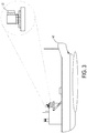
- the camera 12 may be a remote controlled camera on board a maritime vessel 40.
- a distance from the camera 12 to the maritime vessel 40 may be fixed, but both the maritime vessel 40 and camera 12 may change location and orientation while the maritime vessel 40 traverses a body of water.
- the camera 12 is shore-mounted as in FIG. 4
- the distance from the camera 12 to the maritime vessel 40 may not be fixed, but the camera 12 may capture a steady image stream without being tossed about by moving water. In this case, multiple cameras 12 may be used at different locations as the marine vessel 40 travels.
- the camera position 23 may be at least partially based on a feedback signal from the camera 12 indicating a current position 42 of the camera 12.
- FIG. 5 depicts a response to feedback from the camera.
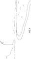
- the image 16 and/or the virtual marine environment 32 may be partially transparent such that both are simultaneously visible when displayed. Initially, the virtual marine environment 32 and the image 16 are misaligned in FIG. 5 . As the maritime vessel 40 of FIG. 3 traverses a body of water, such misalignment may temporarily occur.
- the marine environment display device 10 may receive user input 46 via input device 48 requesting a change in field of view of the camera 12. The camera 12 may move in response, then send the feedback signal to indicate the current position 42 of the camera 12, including an orientation, to the marine environment display device 10.
- the marine environment display device 10 may use the current position 42 of the camera 12 and a current position of the maritime vessel as determined by, for example, a geo-positional sensor such as a global positioning system (GPS) receiver, to obtain a relative position of the camera 12.
- a current attitude of the maritime vessel 40 may be determined by a three-direction attitude sensor and used to obtain the relative position of the camera 12.
- the relative position of the camera 12 may be used to determine the field of view of the camera 12 such that it may be aligned with the virtual field of view of the virtual marine environment 32.
- the camera 12 may comprise a gyroscope, an accelerometer, and/or a GPS receiver, used in any combination to derive the current position 42 of the camera.
- An altitude difference between the camera 12 and the marine environment display device 10 or the GPS receiver of the maritime vessel 40 may also be measured and inputted by an operator during a setup operation.
- the camera 12 may also determine the current position 42 by tracking mechanical movement of the camera 12, for example. Not only may the alignment be improved in this manner, but the location information of the projected image 44 may also be more accurate, as well as the position corresponding to the object location 20.
- the object location 20 may be received from an external source 50, which may be at least one of chart data, Automatic Identification System (AIS), Automatic Radar Plotting Aid (ARPA), and Digital Selective Calling (DSC), for example.
- the chart data may also be stored within the marine environment display device 10.
- ARPA Automatic Identification System
- objects along the same line of sight, particularly on a horizon, may not all be detectable. For instance, if a ship is behind a land mass and blocked from the field of view of the camera 12, the object location 20 of the ship may not be received through radar. However, if the object location 20 of the ship is emitted by, for example, a transponder, the locations 20 of both overlapping objects may be received by the marine environment display device 10.
- the marine environment display device 10 may further comprise an identification receiver 52 configured to receive an identification 54 of the object.
- the object may be a fixed object, and the object location 20 may be received from the chart data.
- the fixed object may be a lighthouse or other object that does not move.
- the object may be a moving object, and the object location 20 may be received from at least one of AIS, ARPA, and DSC.
- the moving object may be one of various types of maritime vessels or buoys, for example.
- FIG. 6 is an illustrative example of object indicators as icons on the projected image 44.
- the object indicator 56A-E may be an icon or symbol with a shape and/or a color that is based on the identification 54.
- object indicator 56A may represent a land mass and have the shape of the land mass as determined from the chart data.
- Object indicator 56B may be in the shape of a lighthouse per the identification 54 and the object location 20 and the identification 54 may be received from the chart data or ARPA.
- object indicators 56C-E may have a sailboat shape, buoy shape, and barge shape, and the object location 20 and identification 54 may be received from AIS, ARPA, and DSC, respectively. Any other suitable marine communication and identification method may be used.
- the icons 56A-E may be superimposed on the respective objects captured in projected image 44.
- different colors are represented by different patterns, e.g. the horizontal stripes of object indicator 56D may represent green, and the vertical stripes of object indicator 56C may represent red.
- the appearance of the icon e.g. the color, may be used to indicate danger or any other current status. For instance, if a projected course of object indicator 56C is calculated to collide with that of the maritime vessel 40, object indicator 56C may flash or become red.
- Different colors may also designate fixed versus moving objects, different speeds, different external sources 50, etc.
- FIG. 7 is an illustrative example of the object indicators as text labels.
- the object indicator may be a text label, which may be descriptive of the object, the object location, etc., or it may be arbitrarily assigned.
- Text label 58B which reads LIGHTHOUSE, may correspond to lighthouse 60.
- text label 58C may correspond to sailboat 62
- text label 58D may correspond to buoy 64
- text label 58E may correspond to barge 66.
- the object generator 24 may be further configured to reposition the text label to avoid overlapping a second text label of a second object indicator.
- FIG. 8 depicts one of the text labels being repositioned to avoid overlapping another text label.
- sailboat 62 is moving toward buoy 64.
- the text label 58C moves out of the way of text label 58D to avoid overlapping or colliding with the text label 58D.
- text label 58C moves upward, but any suitable combination of movements between text labels 58C and 58D is acceptable.
- the marine environment display device 10 further comprises a selected point receiver 70 configured to receive user input 46 via input device 48 selecting a point of the plurality of points on the projected image, and a location retriever 72 configured to retrieve a location associated with the selected point.
- the display 26 is further configured to display the location of the selected point.
- the marine environment display device 10 may further comprise a calculator 74 configured to calculate a distance to the location of the selected point from the camera location based on the horizon at sea or a Depth Elevation Model on land.
- the display 26 may be further configured to display a distance indicator indicating the distance.
- FIG. 9 depicts one example of displaying the distance indicator and the location of the selected point.
- a selected point 76 illustrated as a small circle, may be selected by the user input 46 through the input device 48.
- the input device 48 may be a touch screen, mouse, keyboard, etc. Selecting the selected point 76 may comprise clicking, tapping, etc. the input device 48 as appropriate, but also may include navigating a cursor over the selected point 76 in the case of displaying the distance.
- the distance indicator 78 points to a value on a vertical scale 80 and the location is displayed by a bearing indicator 82 pointing to a value on a horizontal scale 84.
- the location and/or distance of the selected point are displayed in a label 86, similar to the text labels 58A-E of the object indicators.
- the location may include a latitude, longitude, and/or altitude of the selected point 76.
- the marine environment display device 10 further comprises an operation performer 88 configured to perform a zoom operation and/or a pan operation centered on the selected point.
- the operation is centered on the selected point 76 based on the location associated with the selected point 76.
- FIG. 10 is an illustrative example of the marine environment display device performing a panning operation of the camera.
- the marine environment display device 10 may receive user input 46 to change the field of view of the camera 12 through input device 48.
- the panning operation is centered on the selected point 76, located on the sailboat 62, based on the location retrieved from projected image 44.
- a portion of the projected image 44 may not be available due to lag between the marine environment display device 10 and the camera 12, and this portion may be filled by a buffered image or the virtual marine environment 32 until a current projected image is available.
- FIG. 11 is an illustrative example of the display device performing a zoom in operation
- FIG. 12 is an illustrative example of the display device performing a zoom out operation.
- the zoom operations also involves displaying the virtual marine environment 32 where a portion of the projected image 44 is not available, and the zoom operations Z is also centered on the selected point 76 based on the location retrieved from projected image 44.
- FIGS. 13A and 13B are a flowchart of a method 1300 for georeferencing an image stream of a marine environment captured by a camera.
- the following description of method 1300 is provided with reference to the software and hardware components of the marine environment display device described above and shown in FIGS. 1-4 . It will be appreciated that method 1300 may also be performed in other contexts using other suitable hardware and software components.
- the method 1300 may include receiving an image of the image stream from the camera.
- the method 1300 may include receiving an object location of an object.
- the object location may be received from at least one of chart data, Automatic Identification System (AIS), Automatic Radar Plotting Aid (ARPA), and Digital Selective Calling (DSC).
- AIS Automatic Identification System
- ARPA Automatic Radar Plotting Aid
- DSC Digital Selective Calling
- the object may be a fixed object, or as indicated at 1310, the object may be a moving object.
- the method 1300 may include receiving an identification of the object.
- the method 1300 may include generating, from the image, a projected image having location information associated with each of a plurality of points on the projected image and corresponding to a camera position and field of view of the camera.
- the method 1300 may include providing, from chart data, a virtual marine environment corresponding to the camera position and field of view of the camera.
- the virtual marine environment typically comprises a 3D mesh of a plurality of points built from chart data, which represents the topography of the marine environment surrounding the vessel.
- each of a plurality of points on the virtual marine environment may be associated with the location information and correspond to a respective point of the plurality of points on the projected image.
- the method 1300 may include projecting the image onto the virtual marine environment.
- the method 1300 may include generating an object indicator at a position on the projected image based on the object location and the location information.
- the object indicator may be generated at the position on the projected image based further on each of a plurality of points on the virtual marine environment.
- the object indicator may be, for example, an icon with a shape and/or a color that is based on the identification as indicated at 1326.
- the object indicator may be a text label, and the method 1300 may include repositioning the text label to avoid overlapping a second text label of a second object indicator.
- the method 1300 may include displaying the projected image and the object indicator at the position on the projected image on a display.
- the method 1300 may include receiving a user input selecting a point of the plurality of points on the projected image.
- the method 1300 may include retrieving a location associated with the selected point.
- the method 1300 may include calculating a distance to the location of the selected point from the camera location based on a horizon at sea or a Depth Elevation Model on land.
- the method 1300 may include displaying the location of the selected point and an indicator of the distance on the display.
- the method 1300 may include performing a zoom operation and/or a pan operation centered on the selected point.
- the above described devices and methods may be used to georeference an image stream of a camera such that the image stream may be suitable for use in a navigation suite of a maritime vessel.
- the devices and methods may include projecting an image of the image stream onto a virtual marine environment, associating location information with a plurality of points on the projected image, and representing real-life objects with object indicators on the projected image.
- the methods and processes described herein may be tied to a computing system of one or more computing devices.
- such methods and processes may be implemented as a computer-application program or service, an application-programming interface (API), a library, and/or other computer-program product.
- API application-programming interface
- FIG. 14 schematically shows a non-limiting embodiment of a computing system 1410 that can enact one or more of the methods and processes described above.
- Marine environment display device 10 and camera 12 together may take the form of computing system 1410.
- Computing system 1410 is shown in simplified form.
- Computing system 1410 may take the form of one or more personal computers, server computers, tablet computers, network computing devices, mobile computing devices, mobile communication devices (e.g., smart phone), and/or other computing devices.
- Computing system 1410 includes a logic subsystem 1412 and a dataholding subsystem 1414.
- Computing system 1410 may optionally include a display subsystem 1416, input subsystem 1418, communication subsystem 1420, and/or other components not shown in FIG. 14 .
- Logic subsystem 1412 includes one or more physical devices configured to execute instructions.
- the logic subsystem may be configured to execute instructions that are part of one or more applications, services, programs, routines, libraries, objects, components, data structures, or other logical constructs.
- Such instructions may be implemented to perform a task, implement a data type, transform the state of one or more components, achieve a technical effect, or otherwise arrive at a desired result.
- the logic subsystem may include one or more processors configured to execute software instructions. Additionally or alternatively, the logic subsystem may include one or more hardware or firmware logic subsystems configured to execute hardware or firmware instructions. Processors of the logic subsystem may be single-core or multi-core, and the instructions executed thereon may be configured for sequential, parallel, and/or distributed processing. Individual components of the logic subsystem optionally may be distributed among two or more separate devices, which may be remotely located and/or configured for coordinated processing. Aspects of the logic subsystem may be virtualized and executed by remotely accessible, networked computing devices configured in a cloud-computing configuration.
- Data-holding subsystem 1414 includes one or more physical devices configured to hold instructions executable by the logic subsystem to implement the methods and processes described herein. When such methods and processes are implemented, the state of data-holding subsystem 1414 may be transformed-e.g., to hold different data.
- Data-holding subsystem 1414 may include removable and/or built-in devices.
- Data-holding subsystem 1414 may include optical memory (e.g., CD, DVD, HD-DVD, Blu-Ray Disc, etc.), semiconductor memory (e.g., RAM, EPROM, EEPROM, etc.), and/or magnetic memory (e.g., hard-disk drive, floppy-disk drive, tape drive, MRAM, etc.), among others.
- Data-holding subsystem 1414 may include volatile, nonvolatile, dynamic, static, read/write, read-only, random-access, sequential-access, location-addressable, file-addressable, and/or content-addressable devices.
- data-holding subsystem 1414 includes one or more physical devices.
- aspects of the instructions described herein alternatively may be propagated by a communication medium (e.g., an electromagnetic signal, an optical signal, etc.) that is not held by a physical device for a finite duration.
- a communication medium e.g., an electromagnetic signal, an optical signal, etc.
- logic subsystem 1412 and data-holding subsystem 1414 may be integrated together into one or more hardware-logic components.
- Such hardware-logic components may include field-programmable gate arrays (FPGAs), program- and application-specific integrated circuits (PASIC / ASICs), program- and application-specific standard products (PSSP / ASSPs), system-on-a-chip (SOC), and complex programmable logic devices (CPLDs), for example.
- FPGAs field-programmable gate arrays
- PASIC / ASICs program- and application-specific integrated circuits
- PSSP / ASSPs program- and application-specific standard products
- SOC system-on-a-chip
- CPLDs complex programmable logic devices
- module may be used to describe an aspect of computing system 1410 implemented to perform a particular function.
- a module, program, or engine may be instantiated via logic subsystem 1412 executing instructions held by data-holding subsystem 1414. It will be understood that different modules, programs, and/or engines may be instantiated from the same application, service, code block, object, library, routine, API, function, etc. Likewise, the same module, program, and/or engine may be instantiated by different applications, services, code blocks, objects, routines, APIs, functions, etc.
- module may encompass individual or groups of executable files, data files, libraries, drivers, scripts, database records, etc.
- display subsystem 1416 may be used to present a visual representation of data held by data-holding subsystem 1414.
- This visual representation may take the form of a graphical user interface (GUI).
- GUI graphical user interface
- the state of display subsystem 1416 may likewise be transformed to visually represent changes in the underlying data.
- Display subsystem 1416 may include one or more displays utilizing virtually any type of technology. Such displays may be combined with logic subsystem 1412 and/or data-holding subsystem 1414 in a shared enclosure, or such displays may be peripheral displays.
- input subsystem 1418 may comprise or interface with one or more user-input devices such as a keyboard, mouse, trackball, touch screen, or joystick.
- Input subsystem 1418 may also include a camera such as camera 12 for image and/or image stream input, as well as sensors such as geo-positional, positional, orientational, radar, and sonar sensors.
- communication subsystem 1420 may be configured to communicatively couple computing system 1410 with one or more other computing devices as well as internally couple various parts of computing system 1410 together.
- Communication subsystem 1420 may include wired and/or wireless communication devices compatible with one or more different communication protocols.
- the communication subsystem may be configured for communication via a wireless telephone network, or a wired or wireless local- or wide-area network.
- the communication subsystem may allow computing system 1410 to send and/or receive messages to and/or from other devices via a network such as the Internet.
Landscapes
- Engineering & Computer Science (AREA)
- Multimedia (AREA)
- Signal Processing (AREA)
- Radar, Positioning & Navigation (AREA)
- Remote Sensing (AREA)
- Chemical & Material Sciences (AREA)
- Combustion & Propulsion (AREA)
- Mechanical Engineering (AREA)
- Ocean & Marine Engineering (AREA)
- Physics & Mathematics (AREA)
- General Physics & Mathematics (AREA)
- Theoretical Computer Science (AREA)
- Traffic Control Systems (AREA)
- Processing Or Creating Images (AREA)
Description
- Navigation of maritime vessels typically requires accessing and processing numerous independent streams of data. The geographical position of the vessel, weather, wind speed and direction, tide and current speed, the relation of the position of the vessel to charted surface and subsurface features, measured depth of the water beneath the vessel, speed of the vessel, and the position, bearing, and speed of other vessels are just a few examples of the information that may be processed to allow an individual to safely navigate a maritime environment. A vessel operator may use multiple instruments, charts, and visual information to obtain the necessary information describing a dynamic maritime environment. Sometimes, it can be challenging for the vessel operator to synthesize such data from these multiple sources, and correlate this data with the actual view of the surroundings of the vessel.
US 2004/0239688 A1 discloses a system and method for placing reference locators on a streaming video image taken from a camera mounted on a vehicle.
DE 197 54 582 A1 discloses overlying of known navigation data on a real image of the environment of a ship.
EP 2 466 258 A1 discloses another method and system for augmented navigation.
Further documents relating to the technical field of the invention areUS 2009/0096867 A1 ,US 2011/0064312 ,CA 2 282 064 A1 , andWO 2010/041034 A1 . - The above objects are solved by the claimed matter according to the independent claims.
- To address the above issues, devices and methods for georeferencing an image stream of a marine environment captured by a camera are disclosed herein.
- This Summary is provided to introduce a selection of concepts in a simplified form that are further described below in the Detailed Description. This Summary is not intended to identify key features or essential features of the claimed subject matter, nor is it intended to be used to limit the scope of the claimed subject matter. Furthermore, the claimed subject matter is not limited to implementations that solve any or all disadvantages noted in any part of this disclosure.
-
-
FIG. 1 is a simplified schematic view of a marine environment display device receiving inputs. -
FIG. 2 is an illustrative example of an image being projected onto a virtual marine environment. -
FIG. 3 is an illustrative example of a camera on board a maritime vessel. -
FIG. 4 is an illustrative example of a shore-mounted camera. -
FIG. 5 depicts a response to feedback from the camera. -
FIG. 6 is an illustrative example of object indicators as icons. -
FIG. 7 is an illustrative example of the object indicators as text labels. -
FIG. 8 depicts one of the text labels being repositioned to avoid overlapping another text label. -
FIG. 9 depicts the marine environment display device displaying a distance indicator and a location of a selected point. -
FIG. 10 is an illustrative example of the marine environment display device performing a panning operation of the camera. -
FIG. 11 is an illustrative example of the display device performing a zoom in operation. -
FIG. 12 is an illustrative example of the display device performing a zoom out operation. -
FIGS. 13A and13B are a flowchart of a method for georeferencing an image stream of a marine environment captured by the camera. -
FIG. 14 is a simplified schematic view of an example computing system. - Referring initially to
FIG. 1 , a marineenvironment display device 10 is illustrated, which may be part of a navigation suite of a maritime vessel. The marineenvironment display device 10 is configured to receive inputs from various input sources. It will be appreciated that the marineenvironment display device 10 is for georeferencing an image stream of a marine environment captured by acamera 12. - Accordingly, the marine
environment display device 10 comprises animage receiver 14 configured to receive animage 16 of the image stream from thecamera 12, alocation receiver 18 configured to receive an object location 20 of an object in the marine environment, animage generator 22 configured to generate, from theimage 16, a projected image having location information associated with each of a plurality of points on the projected image and corresponding to acamera position 23 and field of view of thecamera 12, anobject generator 24 configured to generate an object indicator at a position on the projected image based on the object location 20 and the location information, and adisplay 26 configured to display the projected image and the object indicator at the position on the projected image. - The
image generator 22 may comprise achart engine program 28 configured to provide, from chart data, a virtual marine environment corresponding to the camera position and field of view of thecamera 12. The virtual marine environment may be three-dimensional (3D), and it may include a virtual mesh or a surface, for example. As illustrated inFIG. 2 discussed below, each of a plurality of points on the virtual marine environment may be associated with the location information and correspond to a respective point of the plurality of points on the projected image. Theimage generator 22 may be configured to generate the projected image by projecting theimage 16 onto the virtual marine environment. -
FIG. 2 is an illustrative example of the image being projected onto the virtual marine environment. Avirtual camera 30 may be positioned at a projection point corresponding to the camera position of thecamera 12 and having a virtual field of view corresponding to the field of view of thecamera 12. Various lines of sight within the virtual field of view of thevirtual camera 30 are indicated inFIG. 2 by dashed lines until intersecting theimage 16, and then by dotted lines until intersecting the virtualmarine environment 32. For example, one line of sight ofvirtual camera 30 intersects theimage 16 at apoint 34 and intersects the virtualmarine environment 32 at apoint 36 such thatpoint 34 may correspond topoint 36.Point 34 may be one of a plurality of points of theimage 16, indicated by plus signs inFIG. 2 .Point 36 may be one of a plurality of points of the virtualmarine environment 32, indicated by circles. Theobject generator 24 ofFIG. 1 may generate the object indicator at the position on the projected image based on the object location 20 and each of the plurality of points on the virtualmarine environment 32. - A
point 38, represented by an X inFIG. 2 , may correspond to a point on theimage 16 in the sky. Because the sky is infinitely far away from thecamera 12,point 38 may not be able to be projected upon in this manner. The sky, represented by a hashed plane, may not exist in the virtualmarine environment 32. When the projected image is generated, the sky may be represented as in theimage 16, but the location information of points therein may not be obtainable. However, each point, pixel, or very small area of the projected image within the marine environment itself may include the respective location information such that the projected image may be considered to be georeferenced. -
FIG. 3 is an illustrative example of the camera on board a maritime vessel, andFIG. 4 is an illustrative example of a shore-mounted camera, an alternative to the on-board camera ofFIG. 3 . With regard toFIG. 3 , thecamera 12 may be a remote controlled camera on board amaritime vessel 40. When thecamera 12 is on board, a distance from thecamera 12 to themaritime vessel 40 may be fixed, but both themaritime vessel 40 andcamera 12 may change location and orientation while themaritime vessel 40 traverses a body of water. When thecamera 12 is shore-mounted as inFIG. 4 , the distance from thecamera 12 to themaritime vessel 40 may not be fixed, but thecamera 12 may capture a steady image stream without being tossed about by moving water. In this case,multiple cameras 12 may be used at different locations as themarine vessel 40 travels. - Returning briefly to
FIG. 1 , thecamera position 23 may be at least partially based on a feedback signal from thecamera 12 indicating acurrent position 42 of thecamera 12.FIG. 5 depicts a response to feedback from the camera. In the projectedimage 44, theimage 16 and/or the virtualmarine environment 32 may be partially transparent such that both are simultaneously visible when displayed. Initially, the virtualmarine environment 32 and theimage 16 are misaligned inFIG. 5 . As themaritime vessel 40 ofFIG. 3 traverses a body of water, such misalignment may temporarily occur. Additionally, the marineenvironment display device 10 may receive user input 46 viainput device 48 requesting a change in field of view of thecamera 12. Thecamera 12 may move in response, then send the feedback signal to indicate thecurrent position 42 of thecamera 12, including an orientation, to the marineenvironment display device 10. - In order to obtain an accurate alignment of the virtual
marine environment 32 and theimage 16, if the marineenvironment display device 10 is mounted on themaritime vessel 40, the marineenvironment display device 10 may use thecurrent position 42 of thecamera 12 and a current position of the maritime vessel as determined by, for example, a geo-positional sensor such as a global positioning system (GPS) receiver, to obtain a relative position of thecamera 12. In addition, a current attitude of themaritime vessel 40 may be determined by a three-direction attitude sensor and used to obtain the relative position of thecamera 12. The relative position of thecamera 12 may be used to determine the field of view of thecamera 12 such that it may be aligned with the virtual field of view of the virtualmarine environment 32. - The
camera 12 may comprise a gyroscope, an accelerometer, and/or a GPS receiver, used in any combination to derive thecurrent position 42 of the camera. An altitude difference between thecamera 12 and the marineenvironment display device 10 or the GPS receiver of themaritime vessel 40 may also be measured and inputted by an operator during a setup operation. Thecamera 12 may also determine thecurrent position 42 by tracking mechanical movement of thecamera 12, for example. Not only may the alignment be improved in this manner, but the location information of the projectedimage 44 may also be more accurate, as well as the position corresponding to the object location 20. - Returning to
Fig. 1 , the object location 20 may be received from anexternal source 50, which may be at least one of chart data, Automatic Identification System (AIS), Automatic Radar Plotting Aid (ARPA), and Digital Selective Calling (DSC), for example. The chart data may also be stored within the marineenvironment display device 10. When the object location 20 is received from anexternal source 50 such as ARPA that utilizes radar, objects along the same line of sight, particularly on a horizon, may not all be detectable. For instance, if a ship is behind a land mass and blocked from the field of view of thecamera 12, the object location 20 of the ship may not be received through radar. However, if the object location 20 of the ship is emitted by, for example, a transponder, the locations 20 of both overlapping objects may be received by the marineenvironment display device 10. - The marine
environment display device 10 may further comprise anidentification receiver 52 configured to receive anidentification 54 of the object. The object may be a fixed object, and the object location 20 may be received from the chart data. For example, the fixed object may be a lighthouse or other object that does not move. Alternatively, the object may be a moving object, and the object location 20 may be received from at least one of AIS, ARPA, and DSC. The moving object may be one of various types of maritime vessels or buoys, for example. -
FIG. 6 is an illustrative example of object indicators as icons on the projectedimage 44. Theobject indicator 56A-E may be an icon or symbol with a shape and/or a color that is based on theidentification 54. For example,object indicator 56A may represent a land mass and have the shape of the land mass as determined from the chart data.Object indicator 56B may be in the shape of a lighthouse per theidentification 54 and the object location 20 and theidentification 54 may be received from the chart data or ARPA. Likewise,object indicators 56C-E may have a sailboat shape, buoy shape, and barge shape, and the object location 20 andidentification 54 may be received from AIS, ARPA, and DSC, respectively. Any other suitable marine communication and identification method may be used. Theicons 56A-E may be superimposed on the respective objects captured in projectedimage 44. - In
Fig. 6 , different colors are represented by different patterns, e.g. the horizontal stripes ofobject indicator 56D may represent green, and the vertical stripes ofobject indicator 56C may represent red. The appearance of the icon, e.g. the color, may be used to indicate danger or any other current status. For instance, if a projected course ofobject indicator 56C is calculated to collide with that of themaritime vessel 40,object indicator 56C may flash or become red. Different colors may also designate fixed versus moving objects, different speeds, differentexternal sources 50, etc. -
FIG. 7 is an illustrative example of the object indicators as text labels. The object indicator may be a text label, which may be descriptive of the object, the object location, etc., or it may be arbitrarily assigned.Text label 58B, which reads LIGHTHOUSE, may correspond tolighthouse 60. Likewise,text label 58C may correspond tosailboat 62,text label 58D may correspond to buoy 64, andtext label 58E may correspond tobarge 66. - Additionally, the
object generator 24 may be further configured to reposition the text label to avoid overlapping a second text label of a second object indicator.FIG. 8 depicts one of the text labels being repositioned to avoid overlapping another text label. In an expanded view ofarea 68 ofFIG. 7 ,sailboat 62 is moving towardbuoy 64. As thesailboat 62 approaches thebuoy 64, thetext label 58C moves out of the way oftext label 58D to avoid overlapping or colliding with thetext label 58D. In the depicted example,text label 58C moves upward, but any suitable combination of movements betweentext labels - Returning to
FIG. 1 , the marineenvironment display device 10 further comprises a selectedpoint receiver 70 configured to receive user input 46 viainput device 48 selecting a point of the plurality of points on the projected image, and alocation retriever 72 configured to retrieve a location associated with the selected point. Thedisplay 26 is further configured to display the location of the selected point. When displaying the location of the selected point, the marineenvironment display device 10 may further comprise acalculator 74 configured to calculate a distance to the location of the selected point from the camera location based on the horizon at sea or a Depth Elevation Model on land. Thedisplay 26 may be further configured to display a distance indicator indicating the distance. -
FIG. 9 depicts one example of displaying the distance indicator and the location of the selected point. A selectedpoint 76, illustrated as a small circle, may be selected by the user input 46 through theinput device 48. Theinput device 48 may be a touch screen, mouse, keyboard, etc. Selecting the selectedpoint 76 may comprise clicking, tapping, etc. theinput device 48 as appropriate, but also may include navigating a cursor over the selectedpoint 76 in the case of displaying the distance. In one implementation, thedistance indicator 78 points to a value on avertical scale 80 and the location is displayed by a bearingindicator 82 pointing to a value on ahorizontal scale 84. In another implementation, the location and/or distance of the selected point are displayed in alabel 86, similar to the text labels 58A-E of the object indicators. In this case, the location may include a latitude, longitude, and/or altitude of the selectedpoint 76. - The marine
environment display device 10 further comprises an operation performer 88 configured to perform a zoom operation and/or a pan operation centered on the selected point. The operation is centered on the selectedpoint 76 based on the location associated with the selectedpoint 76. Accordingly,FIG. 10 is an illustrative example of the marine environment display device performing a panning operation of the camera. The marineenvironment display device 10 may receive user input 46 to change the field of view of thecamera 12 throughinput device 48. The panning operation is centered on the selectedpoint 76, located on thesailboat 62, based on the location retrieved from projectedimage 44. When panning, a portion of the projectedimage 44 may not be available due to lag between the marineenvironment display device 10 and thecamera 12, and this portion may be filled by a buffered image or the virtualmarine environment 32 until a current projected image is available. -
FIG. 11 is an illustrative example of the display device performing a zoom in operation, whileFIG. 12 is an illustrative example of the display device performing a zoom out operation. Similarly to the panning operation, the zoom operations also involves displaying the virtualmarine environment 32 where a portion of the projectedimage 44 is not available, and the zoom operations Z is also centered on the selectedpoint 76 based on the location retrieved from projectedimage 44. -
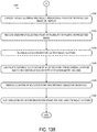
FIGS. 13A and13B are a flowchart of amethod 1300 for georeferencing an image stream of a marine environment captured by a camera. The following description ofmethod 1300 is provided with reference to the software and hardware components of the marine environment display device described above and shown inFIGS. 1-4 . It will be appreciated thatmethod 1300 may also be performed in other contexts using other suitable hardware and software components. - With reference to
FIG. 13A , at 1302 themethod 1300 may include receiving an image of the image stream from the camera. At 1304 themethod 1300 may include receiving an object location of an object. At 1306 the object location may be received from at least one of chart data, Automatic Identification System (AIS), Automatic Radar Plotting Aid (ARPA), and Digital Selective Calling (DSC). It will be appreciated that as indicated at 1308, the object may be a fixed object, or as indicated at 1310, the object may be a moving object. Further, at 1312, themethod 1300 may include receiving an identification of the object. - At 1314 the
method 1300 may include generating, from the image, a projected image having location information associated with each of a plurality of points on the projected image and corresponding to a camera position and field of view of the camera. At 1316 themethod 1300 may include providing, from chart data, a virtual marine environment corresponding to the camera position and field of view of the camera. As described above, the virtual marine environment typically comprises a 3D mesh of a plurality of points built from chart data, which represents the topography of the marine environment surrounding the vessel. At 1318 each of a plurality of points on the virtual marine environment may be associated with the location information and correspond to a respective point of the plurality of points on the projected image. At 1320 themethod 1300 may include projecting the image onto the virtual marine environment. - At 1322 the
method 1300 may include generating an object indicator at a position on the projected image based on the object location and the location information. At 1324 the object indicator may be generated at the position on the projected image based further on each of a plurality of points on the virtual marine environment. The object indicator may be, for example, an icon with a shape and/or a color that is based on the identification as indicated at 1326. Alternatively, as indicated at 1328, the object indicator may be a text label, and themethod 1300 may include repositioning the text label to avoid overlapping a second text label of a second object indicator. - Turning to
FIG. 13B , at 1330 themethod 1300 may include displaying the projected image and the object indicator at the position on the projected image on a display. At 1332 themethod 1300 may include receiving a user input selecting a point of the plurality of points on the projected image. At 1334 themethod 1300 may include retrieving a location associated with the selected point. At 1336 themethod 1300 may include calculating a distance to the location of the selected point from the camera location based on a horizon at sea or a Depth Elevation Model on land. At 1338 themethod 1300 may include displaying the location of the selected point and an indicator of the distance on the display. At 1340 themethod 1300 may include performing a zoom operation and/or a pan operation centered on the selected point. - The above described devices and methods may be used to georeference an image stream of a camera such that the image stream may be suitable for use in a navigation suite of a maritime vessel. The devices and methods may include projecting an image of the image stream onto a virtual marine environment, associating location information with a plurality of points on the projected image, and representing real-life objects with object indicators on the projected image.
- In some embodiments, the methods and processes described herein may be tied to a computing system of one or more computing devices. In particular, such methods and processes may be implemented as a computer-application program or service, an application-programming interface (API), a library, and/or other computer-program product.
-
FIG. 14 schematically shows a non-limiting embodiment of acomputing system 1410 that can enact one or more of the methods and processes described above. Marineenvironment display device 10 andcamera 12 together may take the form ofcomputing system 1410.Computing system 1410 is shown in simplified form.Computing system 1410 may take the form of one or more personal computers, server computers, tablet computers, network computing devices, mobile computing devices, mobile communication devices (e.g., smart phone), and/or other computing devices. -
Computing system 1410 includes alogic subsystem 1412 and adataholding subsystem 1414.Computing system 1410 may optionally include adisplay subsystem 1416,input subsystem 1418,communication subsystem 1420, and/or other components not shown inFIG. 14 . -
Logic subsystem 1412 includes one or more physical devices configured to execute instructions. For example, the logic subsystem may be configured to execute instructions that are part of one or more applications, services, programs, routines, libraries, objects, components, data structures, or other logical constructs. Such instructions may be implemented to perform a task, implement a data type, transform the state of one or more components, achieve a technical effect, or otherwise arrive at a desired result. - The logic subsystem may include one or more processors configured to execute software instructions. Additionally or alternatively, the logic subsystem may include one or more hardware or firmware logic subsystems configured to execute hardware or firmware instructions. Processors of the logic subsystem may be single-core or multi-core, and the instructions executed thereon may be configured for sequential, parallel, and/or distributed processing. Individual components of the logic subsystem optionally may be distributed among two or more separate devices, which may be remotely located and/or configured for coordinated processing. Aspects of the logic subsystem may be virtualized and executed by remotely accessible, networked computing devices configured in a cloud-computing configuration.
- Data-holding
subsystem 1414 includes one or more physical devices configured to hold instructions executable by the logic subsystem to implement the methods and processes described herein. When such methods and processes are implemented, the state of data-holdingsubsystem 1414 may be transformed-e.g., to hold different data. - Data-holding
subsystem 1414 may include removable and/or built-in devices. Data-holdingsubsystem 1414 may include optical memory (e.g., CD, DVD, HD-DVD, Blu-Ray Disc, etc.), semiconductor memory (e.g., RAM, EPROM, EEPROM, etc.), and/or magnetic memory (e.g., hard-disk drive, floppy-disk drive, tape drive, MRAM, etc.), among others. Data-holdingsubsystem 1414 may include volatile, nonvolatile, dynamic, static, read/write, read-only, random-access, sequential-access, location-addressable, file-addressable, and/or content-addressable devices. - It will be appreciated that data-holding
subsystem 1414 includes one or more physical devices. However, aspects of the instructions described herein alternatively may be propagated by a communication medium (e.g., an electromagnetic signal, an optical signal, etc.) that is not held by a physical device for a finite duration. - Aspects of
logic subsystem 1412 and data-holdingsubsystem 1414 may be integrated together into one or more hardware-logic components. Such hardware-logic components may include field-programmable gate arrays (FPGAs), program- and application-specific integrated circuits (PASIC / ASICs), program- and application-specific standard products (PSSP / ASSPs), system-on-a-chip (SOC), and complex programmable logic devices (CPLDs), for example. - The terms "module," "program," and "engine" may be used to describe an aspect of
computing system 1410 implemented to perform a particular function. In some cases, a module, program, or engine may be instantiated vialogic subsystem 1412 executing instructions held by data-holdingsubsystem 1414. It will be understood that different modules, programs, and/or engines may be instantiated from the same application, service, code block, object, library, routine, API, function, etc. Likewise, the same module, program, and/or engine may be instantiated by different applications, services, code blocks, objects, routines, APIs, functions, etc. The terms "module," "program," and "engine" may encompass individual or groups of executable files, data files, libraries, drivers, scripts, database records, etc. - When included,
display subsystem 1416 may be used to present a visual representation of data held by data-holdingsubsystem 1414. This visual representation may take the form of a graphical user interface (GUI). As the herein described methods and processes change the data held by the data-holding subsystem, and thus transform the state of the data-holding subsystem, the state ofdisplay subsystem 1416 may likewise be transformed to visually represent changes in the underlying data.Display subsystem 1416 may include one or more displays utilizing virtually any type of technology. Such displays may be combined withlogic subsystem 1412 and/or data-holdingsubsystem 1414 in a shared enclosure, or such displays may be peripheral displays. - When included,
input subsystem 1418 may comprise or interface with one or more user-input devices such as a keyboard, mouse, trackball, touch screen, or joystick.Input subsystem 1418 may also include a camera such ascamera 12 for image and/or image stream input, as well as sensors such as geo-positional, positional, orientational, radar, and sonar sensors. - When included,
communication subsystem 1420 may be configured to communicatively couplecomputing system 1410 with one or more other computing devices as well as internally couple various parts ofcomputing system 1410 together.Communication subsystem 1420 may include wired and/or wireless communication devices compatible with one or more different communication protocols. As non-limiting examples, the communication subsystem may be configured for communication via a wireless telephone network, or a wired or wireless local- or wide-area network. In some embodiments, the communication subsystem may allowcomputing system 1410 to send and/or receive messages to and/or from other devices via a network such as the Internet. - It will be understood that the configurations and/or approaches described herein are exemplary in nature, and that these specific embodiments or examples are not to be considered in a limiting sense, because numerous variations are possible. The specific routines or methods described herein may represent one or more of any number of processing strategies. As such, various acts illustrated and/or described may be performed in the sequence illustrated and/or described, in other sequences, in parallel, or omitted. Likewise, the order of the above-described processes may be changed.
Claims (11)
- A marine environment display device (10) for geo-referencing an image stream of a marine environment captured by a camera (12), the marine environment display device (10) comprising:an image receiver (14) configured to receive an image of the image stream from the camera (12);a location receiver (18) configured to receive an object location (20) of an object;an image generator (22) configured to generate, from the image (16), a projected image having a virtual marine environment (32) provided from chart data and corresponding to the camera position and field of view of the camera, wherein location information is associated with each of a plurality of points on the projected image and the image (16) is projected onto the virtual marine environment (32);an object generator (24) configured to generate an object indicator (56,58) at a position on the projected image based on the object location (20) and the location information, wherein the object indicator (56, 58) is generated at the position on the projected image based further on each of a plurality of points on the virtual marine environment;a display (26) configured to display the projected image and the object indicator (56,58) at the position on the projected image;a selected point receiver (70) configured to receive via an input device (48) a user input (46) selecting a point of the plurality of points on the projected image;a location retriever (72) configured to retrieve a location associated with the selected point;wherein the display (26) is further configured to display the location of the selected point;an operation performer (88) configured to perform a zoom operation and/or a pan operation centered on the selected point, whereinthe operation performer (88) is further adapted to display during a panning or zoom operation centered on the selected point the virtual marine environment (32) in a portion of the display device where the projected image (44) is not available until a current projected image (44) is available.
- The marine environment display device (10) of claim 1, wherein:the camera (12) is a remote controlled camera (12) on board a maritime vessel; andthe camera position (23) is at least partially based on a feedback signal from the camera (12) indicating a current position of the camera (12).
- The marine environment display device (10) according to claim 1 or 2, wherein the object location (20) is received from at least one of chart data, Automatic Identification System (AIS), Automatic Radar Plotting Aid (ARPA), and Digital Selective Calling (DSC).
- The marine environment display device (10) according to any one of claims 1 to 3, further comprising:
an identification receiver (52) configured to receive an identification of the object, wherein:the object is a fixed object; andthe object location (20) is received from chart data. - The marine environment display device (10) according to any one of claims 1 to 4, further comprising:
an identification receiver (52) configured to receive an identification of the object, wherein:the object is a moving object; andthe object location (20) is received from at least one of Automatic Identification System (AIS), Automatic Radar Plotting Aid (ARPA), and Digital Selective Calling (DSC). - The marine environment display device (10) according to any one of claims 1 to 5, wherein the object indicator (56,58) is an icon with a shape and/or a color that is based on the identification.
- The marine environment display device (10) according to any one of claims 1 to 6, wherein:the object indicator (56,58) is a text label; andthe object generator (24) is further configured to reposition the text label to avoid overlapping a second text label of a second object indicator (56,58).
- The marine environment display device (10) according to claim 1 or to claim 1 and any one of claims 2 to 7, wherein when displaying the location of the selected point, the marine environment display device (10) further comprises:a calculator (74) configured to calculate a distance to the location of the selected point from the camera (12) location based on a horizon at sea or a Depth Elevation Model on land;wherein the display (26) is further configured to display a distance indicator (78) indicating the distance.
- In a marine environment display device (10), a method for georeferencing an image stream of a marine environment captured by a camera (12), the method comprising:receiving an image of the image stream from the camera (12);receiving an object location (20) of an object;generating, from the image, a projected image having from chart data a virtual marine environment corresponding to the camera position and field of view of the camera, wherein location information is associated with each of a plurality of points on the projected image and corresponding to a camera position (23) and field of view of the camera (12);projecting the image onto the virtual marine environment;generating an object indicator (56,58) at a position on the projected image based on the object location (20) and the location information, wherein the object indicator (56, 58) is generated at the position on the projected image based further on each of a plurality of points on the virtual marine environment; anddisplaying the projected image and the object indicator (56,58) at the position on the projected image on a display (26);receiving via an input device (48) a user input (46) selecting a point of the plurality of points on the projected image (44);retrieving a location associated with the selected point;displaying the location of the selected point;performing a zoom operation and/or a pan operation centered on a selected point,displaying, during the panning or zoom operation centered to the selected point, the virtual marine environment (32) where the projected image (44) is not available until a current projected image (44) is available.
- The method of claim 9, wherein the object location (20) is received from at least one of chart data, Automatic Identification System (AIS), Automatic Radar Plotting Aid (ARPA), and Digital Selective Calling (DSC).
- The method according to claim 9 or 10, wherein:the object is a moving object; andthe object location (20) is received from at least one of Automatic Identification System (AIS), Automatic Radar Plotting Aid (ARPA), and Digital Selective Calling (DSC);the method further comprising receiving an identification of the object.
Applications Claiming Priority (1)
| Application Number | Priority Date | Filing Date | Title |
|---|---|---|---|
| US14/292,732 US9826164B2 (en) | 2014-05-30 | 2014-05-30 | Marine environment display device |
Publications (2)
| Publication Number | Publication Date |
|---|---|
| EP2950530A1 EP2950530A1 (en) | 2015-12-02 |
| EP2950530B1 true EP2950530B1 (en) | 2020-04-01 |
Family
ID=53432946
Family Applications (1)
| Application Number | Title | Priority Date | Filing Date |
|---|---|---|---|
| EP15166550.2A Active EP2950530B1 (en) | 2014-05-30 | 2015-05-06 | Marine environment display device |
Country Status (2)
| Country | Link |
|---|---|
| US (1) | US9826164B2 (en) |
| EP (1) | EP2950530B1 (en) |
Families Citing this family (21)
| Publication number | Priority date | Publication date | Assignee | Title |
|---|---|---|---|---|
| US20140176661A1 (en) * | 2012-12-21 | 2014-06-26 | G. Anthony Reina | System and method for surgical telementoring and training with virtualized telestration and haptic holograms, including metadata tagging, encapsulation and saving multi-modal streaming medical imagery together with multi-dimensional [4-d] virtual mesh and multi-sensory annotation in standard file formats used for digital imaging and communications in medicine (dicom) |
| JP2016090347A (en) * | 2014-10-31 | 2016-05-23 | 古野電気株式会社 | Remote notification device, information remote notification system and information remote notification method |
| ITUB20152951A1 (en) * | 2015-08-06 | 2017-02-06 | Thomas Bleiner | MULTIFUNCTIONAL VISUALIZATION SYSTEM FOR NAUTICAL USE |
| WO2018178506A1 (en) * | 2017-03-30 | 2018-10-04 | Scopesensor Oy | A method, a system and a device for displaying real-time video images from around a vehicle |
| US10712159B2 (en) * | 2017-04-10 | 2020-07-14 | Martha Grabowski | Critical system operations and simulations using wearable immersive augmented reality technology |
| JP6857546B2 (en) | 2017-05-24 | 2021-04-14 | 古野電気株式会社 | Video generator and video generation method |
| EP3633627A4 (en) | 2017-05-24 | 2021-03-24 | Furuno Electric Co., Ltd. | Video generation device |
| WO2018216535A1 (en) | 2017-05-24 | 2018-11-29 | 古野電気株式会社 | Video generation device |
| EP3633985B1 (en) * | 2017-05-24 | 2023-02-15 | Furuno Electric Co., Ltd. | Video generation device |
| US10160274B1 (en) * | 2017-10-23 | 2018-12-25 | GM Global Technology Operations LLC | Method and apparatus that generate position indicators for towable object |
| US11934187B2 (en) * | 2017-12-01 | 2024-03-19 | Onesubsea Ip Uk Limited | Systems and methods of pilot assist for subsea vehicles |
| CN111357281B (en) | 2017-12-25 | 2023-05-30 | 古野电气株式会社 | Video generating device and video generating method |
| JP7191595B2 (en) | 2018-08-30 | 2022-12-19 | 株式会社 商船三井 | Image generation device and image generation method |
| US10922981B2 (en) * | 2018-12-05 | 2021-02-16 | Windward Ltd. | Risk event identification in maritime data and usage thereof |
| WO2020142048A2 (en) * | 2018-12-31 | 2020-07-09 | Havelsan Hava Elektroni̇k Sanayi̇ Ve Ti̇caret Anoni̇m Şi̇rketi̇ | Augmented virtual reality tactical state display system (asger-tds) |
| JP7257200B2 (en) * | 2019-03-19 | 2023-04-13 | ヤマハ発動機株式会社 | Ships and navigation aids |
| US11080821B2 (en) * | 2019-03-28 | 2021-08-03 | United States Of America As Represented By The Secretary Of The Navy | Automated benthic ecology system and method for stereoscopic imagery generation |
| WO2021049221A1 (en) * | 2019-09-09 | 2021-03-18 | 古野電気株式会社 | Ship information display system, ship information display method, image generation device, and program |
| DE102020103466A1 (en) | 2020-02-11 | 2021-08-12 | Raytheon Anschütz Gmbh | Method for determining the position of a watercraft by means of optical bearing |
| WO2022137953A1 (en) * | 2020-12-24 | 2022-06-30 | 古野電気株式会社 | Sea mark identification device, autonomous navigation system, sea mark identification method, and program |
| WO2022153788A1 (en) * | 2021-01-18 | 2022-07-21 | 古野電気株式会社 | Ar piloting system and ar piloting method |
Family Cites Families (17)
| Publication number | Priority date | Publication date | Assignee | Title |
|---|---|---|---|---|
| US3507993A (en) * | 1968-01-04 | 1970-04-21 | Us Navy | Situation display for aircraft navigation employing crt display of the mean course line |
| JPH04195397A (en) * | 1990-11-27 | 1992-07-15 | Matsushita Electric Ind Co Ltd | Road trouble monitor device |
| US5528735A (en) * | 1993-03-23 | 1996-06-18 | Silicon Graphics Inc. | Method and apparatus for displaying data within a three-dimensional information landscape |
| DE19754582A1 (en) * | 1997-12-09 | 1999-06-10 | Benedikt Zeyen | Easing task of ship navigation with assistance of hyper reality |
| CA2282064A1 (en) | 1999-07-30 | 2001-01-30 | Intersite Technologies Inc. | A system and method for use with a moveable platform |
| US6995788B2 (en) * | 2001-10-10 | 2006-02-07 | Sony Computer Entertainment America Inc. | System and method for camera navigation |
| US7071970B2 (en) | 2003-03-10 | 2006-07-04 | Charles Benton | Video augmented orientation sensor |
| US7456847B2 (en) * | 2004-08-12 | 2008-11-25 | Russell Steven Krajec | Video with map overlay |
| US8942483B2 (en) * | 2009-09-14 | 2015-01-27 | Trimble Navigation Limited | Image-based georeferencing |
| US8019490B2 (en) * | 2006-09-29 | 2011-09-13 | Applied Minds, Llc | Imaging and display system to aid helicopter landings in brownout conditions |
| NO330248B1 (en) * | 2007-10-11 | 2011-03-14 | Aptomar As | A marine sock system |
| GB0818561D0 (en) | 2008-10-09 | 2008-11-19 | Isis Innovation | Visual tracking of objects in images, and segmentation of images |
| US8260489B2 (en) * | 2009-04-03 | 2012-09-04 | Certusview Technologies, Llc | Methods, apparatus, and systems for acquiring and analyzing vehicle data and generating an electronic representation of vehicle operations |
| CA2771286C (en) * | 2009-08-11 | 2016-08-30 | Certusview Technologies, Llc | Locating equipment communicatively coupled to or equipped with a mobile/portable device |
| US8400294B2 (en) * | 2009-12-21 | 2013-03-19 | Garmin Switzerland Gmbh | Transit stop detection |
| US8265866B2 (en) * | 2010-12-15 | 2012-09-11 | The Boeing Company | Methods and systems for augmented navigation |
| US20130265333A1 (en) | 2011-09-08 | 2013-10-10 | Lucas B. Ainsworth | Augmented Reality Based on Imaged Object Characteristics |
-
2014
- 2014-05-30 US US14/292,732 patent/US9826164B2/en active Active
-
2015
- 2015-05-06 EP EP15166550.2A patent/EP2950530B1/en active Active
Non-Patent Citations (1)
| Title |
|---|
| None * |
Also Published As
| Publication number | Publication date |
|---|---|
| EP2950530A1 (en) | 2015-12-02 |
| US20150350552A1 (en) | 2015-12-03 |
| US9826164B2 (en) | 2017-11-21 |
Similar Documents
| Publication | Publication Date | Title |
|---|---|---|
| EP2950530B1 (en) | Marine environment display device | |
| EP3338136B1 (en) | Augmented reality in vehicle platforms | |
| US10929494B2 (en) | Systems and methods for tagging objects for augmented reality | |
| CN111540059B (en) | Enhanced video system providing enhanced environmental awareness | |
| US9030353B2 (en) | Information display device, information display method, and radar apparatus | |
| EP3633319B1 (en) | Video generation device | |
| US11729492B2 (en) | Image generation device and image generation method | |
| CN106054137A (en) | Ship information display device and ship information display method | |
| JP7214402B2 (en) | Image generation device and image generation method | |
| US10783170B2 (en) | Geotagging a landscape photograph | |
| JP6087712B2 (en) | DISTRIBUTION DATA DISPLAY DEVICE, METHOD, AND PROGRAM | |
| KR20150002763A (en) | Electronic sea chart information display device and method for displaying electronic sea chart information | |
| US9534902B2 (en) | Time phased imagery for an artificial point of view | |
| KR102328272B1 (en) | Visualization system of battleground situation and method thereof | |
| US10930079B1 (en) | Techniques for displaying augmentations that represent cadastral lines and other near-ground features | |
| US11175399B2 (en) | Information processing device, information processing method, and storage medium | |
| JP6673699B2 (en) | Terrain display system | |
| CN109283528A (en) | Navigations information display device, navigations information display methods and recording medium | |
| KR102182128B1 (en) | An apparatus and method of making aviation image based on real time position tracking | |
| CN107703954B (en) | Target position surveying method and device for unmanned aerial vehicle and unmanned aerial vehicle | |
| US11967035B1 (en) | Visualizing area covered by drone camera | |
| JP7492059B2 (en) | Periphery monitoring device and surroundings monitoring method | |
| US20240149992A1 (en) | Navigational information displaying device, navigational information displaying method, and a non-transitory computer-readable medium | |
| Thomas et al. | 3D modeling for mobile augmented reality in unprepared environment | |
| EP2819101A1 (en) | Mobile lighting for 3D Rendering |
Legal Events
| Date | Code | Title | Description |
|---|---|---|---|
| AK | Designated contracting states |
Kind code of ref document: A1 Designated state(s): AL AT BE BG CH CY CZ DE DK EE ES FI FR GB GR HR HU IE IS IT LI LT LU LV MC MK MT NL NO PL PT RO RS SE SI SK SM TR |
|
| AX | Request for extension of the european patent |
Extension state: BA ME |
|
| PUAI | Public reference made under article 153(3) epc to a published international application that has entered the european phase |
Free format text: ORIGINAL CODE: 0009012 |
|
| 17P | Request for examination filed |
Effective date: 20160601 |
|
| RBV | Designated contracting states (corrected) |
Designated state(s): AL AT BE BG CH CY CZ DE DK EE ES FI FR GB GR HR HU IE IS IT LI LT LU LV MC MK MT NL NO PL PT RO RS SE SI SK SM TR |
|
| STAA | Information on the status of an ep patent application or granted ep patent |
Free format text: STATUS: EXAMINATION IS IN PROGRESS |
|
| 17Q | First examination report despatched |
Effective date: 20180517 |
|
| GRAP | Despatch of communication of intention to grant a patent |
Free format text: ORIGINAL CODE: EPIDOSNIGR1 |
|
| STAA | Information on the status of an ep patent application or granted ep patent |
Free format text: STATUS: GRANT OF PATENT IS INTENDED |
|
| INTG | Intention to grant announced |
Effective date: 20191025 |
|
| GRAS | Grant fee paid |
Free format text: ORIGINAL CODE: EPIDOSNIGR3 |
|
| GRAA | (expected) grant |
Free format text: ORIGINAL CODE: 0009210 |
|
| STAA | Information on the status of an ep patent application or granted ep patent |
Free format text: STATUS: THE PATENT HAS BEEN GRANTED |
|
| AK | Designated contracting states |
Kind code of ref document: B1 Designated state(s): AL AT BE BG CH CY CZ DE DK EE ES FI FR GB GR HR HU IE IS IT LI LT LU LV MC MK MT NL NO PL PT RO RS SE SI SK SM TR |
|
| REG | Reference to a national code |
Ref country code: GB Ref legal event code: FG4D |
|
| REG | Reference to a national code |
Ref country code: CH Ref legal event code: EP Ref country code: AT Ref legal event code: REF Ref document number: 1252882 Country of ref document: AT Kind code of ref document: T Effective date: 20200415 |
|
| REG | Reference to a national code |
Ref country code: DE Ref legal event code: R096 Ref document number: 602015049691 Country of ref document: DE |
|
| REG | Reference to a national code |
Ref country code: IE Ref legal event code: FG4D |
|
| PG25 | Lapsed in a contracting state [announced via postgrant information from national office to epo] |
Ref country code: BG Free format text: LAPSE BECAUSE OF FAILURE TO SUBMIT A TRANSLATION OF THE DESCRIPTION OR TO PAY THE FEE WITHIN THE PRESCRIBED TIME-LIMIT Effective date: 20200701 |
|
| REG | Reference to a national code |
Ref country code: NL Ref legal event code: MP Effective date: 20200401 |
|
| REG | Reference to a national code |
Ref country code: LT Ref legal event code: MG4D |
|
| PG25 | Lapsed in a contracting state [announced via postgrant information from national office to epo] |
Ref country code: NO Free format text: LAPSE BECAUSE OF FAILURE TO SUBMIT A TRANSLATION OF THE DESCRIPTION OR TO PAY THE FEE WITHIN THE PRESCRIBED TIME-LIMIT Effective date: 20200701 Ref country code: GR Free format text: LAPSE BECAUSE OF FAILURE TO SUBMIT A TRANSLATION OF THE DESCRIPTION OR TO PAY THE FEE WITHIN THE PRESCRIBED TIME-LIMIT Effective date: 20200702 Ref country code: FI Free format text: LAPSE BECAUSE OF FAILURE TO SUBMIT A TRANSLATION OF THE DESCRIPTION OR TO PAY THE FEE WITHIN THE PRESCRIBED TIME-LIMIT Effective date: 20200401 Ref country code: IS Free format text: LAPSE BECAUSE OF FAILURE TO SUBMIT A TRANSLATION OF THE DESCRIPTION OR TO PAY THE FEE WITHIN THE PRESCRIBED TIME-LIMIT Effective date: 20200801 Ref country code: SE Free format text: LAPSE BECAUSE OF FAILURE TO SUBMIT A TRANSLATION OF THE DESCRIPTION OR TO PAY THE FEE WITHIN THE PRESCRIBED TIME-LIMIT Effective date: 20200401 Ref country code: CZ Free format text: LAPSE BECAUSE OF FAILURE TO SUBMIT A TRANSLATION OF THE DESCRIPTION OR TO PAY THE FEE WITHIN THE PRESCRIBED TIME-LIMIT Effective date: 20200401 Ref country code: PT Free format text: LAPSE BECAUSE OF FAILURE TO SUBMIT A TRANSLATION OF THE DESCRIPTION OR TO PAY THE FEE WITHIN THE PRESCRIBED TIME-LIMIT Effective date: 20200817 Ref country code: LT Free format text: LAPSE BECAUSE OF FAILURE TO SUBMIT A TRANSLATION OF THE DESCRIPTION OR TO PAY THE FEE WITHIN THE PRESCRIBED TIME-LIMIT Effective date: 20200401 Ref country code: NL Free format text: LAPSE BECAUSE OF FAILURE TO SUBMIT A TRANSLATION OF THE DESCRIPTION OR TO PAY THE FEE WITHIN THE PRESCRIBED TIME-LIMIT Effective date: 20200401 |
|
| REG | Reference to a national code |
Ref country code: AT Ref legal event code: MK05 Ref document number: 1252882 Country of ref document: AT Kind code of ref document: T Effective date: 20200401 |
|
| PG25 | Lapsed in a contracting state [announced via postgrant information from national office to epo] |
Ref country code: HR Free format text: LAPSE BECAUSE OF FAILURE TO SUBMIT A TRANSLATION OF THE DESCRIPTION OR TO PAY THE FEE WITHIN THE PRESCRIBED TIME-LIMIT Effective date: 20200401 Ref country code: LV Free format text: LAPSE BECAUSE OF FAILURE TO SUBMIT A TRANSLATION OF THE DESCRIPTION OR TO PAY THE FEE WITHIN THE PRESCRIBED TIME-LIMIT Effective date: 20200401 Ref country code: RS Free format text: LAPSE BECAUSE OF FAILURE TO SUBMIT A TRANSLATION OF THE DESCRIPTION OR TO PAY THE FEE WITHIN THE PRESCRIBED TIME-LIMIT Effective date: 20200401 |
|
| PG25 | Lapsed in a contracting state [announced via postgrant information from national office to epo] |
Ref country code: AL Free format text: LAPSE BECAUSE OF FAILURE TO SUBMIT A TRANSLATION OF THE DESCRIPTION OR TO PAY THE FEE WITHIN THE PRESCRIBED TIME-LIMIT Effective date: 20200401 |
|
| REG | Reference to a national code |
Ref country code: DE Ref legal event code: R097 Ref document number: 602015049691 Country of ref document: DE |
|
| PG25 | Lapsed in a contracting state [announced via postgrant information from national office to epo] |
Ref country code: MC Free format text: LAPSE BECAUSE OF FAILURE TO SUBMIT A TRANSLATION OF THE DESCRIPTION OR TO PAY THE FEE WITHIN THE PRESCRIBED TIME-LIMIT Effective date: 20200401 Ref country code: CH Free format text: LAPSE BECAUSE OF NON-PAYMENT OF DUE FEES Effective date: 20200531 Ref country code: DK Free format text: LAPSE BECAUSE OF FAILURE TO SUBMIT A TRANSLATION OF THE DESCRIPTION OR TO PAY THE FEE WITHIN THE PRESCRIBED TIME-LIMIT Effective date: 20200401 Ref country code: AT Free format text: LAPSE BECAUSE OF FAILURE TO SUBMIT A TRANSLATION OF THE DESCRIPTION OR TO PAY THE FEE WITHIN THE PRESCRIBED TIME-LIMIT Effective date: 20200401 Ref country code: IT Free format text: LAPSE BECAUSE OF FAILURE TO SUBMIT A TRANSLATION OF THE DESCRIPTION OR TO PAY THE FEE WITHIN THE PRESCRIBED TIME-LIMIT Effective date: 20200401 Ref country code: LI Free format text: LAPSE BECAUSE OF NON-PAYMENT OF DUE FEES Effective date: 20200531 Ref country code: SM Free format text: LAPSE BECAUSE OF FAILURE TO SUBMIT A TRANSLATION OF THE DESCRIPTION OR TO PAY THE FEE WITHIN THE PRESCRIBED TIME-LIMIT Effective date: 20200401 Ref country code: EE Free format text: LAPSE BECAUSE OF FAILURE TO SUBMIT A TRANSLATION OF THE DESCRIPTION OR TO PAY THE FEE WITHIN THE PRESCRIBED TIME-LIMIT Effective date: 20200401 Ref country code: RO Free format text: LAPSE BECAUSE OF FAILURE TO SUBMIT A TRANSLATION OF THE DESCRIPTION OR TO PAY THE FEE WITHIN THE PRESCRIBED TIME-LIMIT Effective date: 20200401 Ref country code: ES Free format text: LAPSE BECAUSE OF FAILURE TO SUBMIT A TRANSLATION OF THE DESCRIPTION OR TO PAY THE FEE WITHIN THE PRESCRIBED TIME-LIMIT Effective date: 20200401 |
|
| PLBE | No opposition filed within time limit |
Free format text: ORIGINAL CODE: 0009261 |
|
| STAA | Information on the status of an ep patent application or granted ep patent |
Free format text: STATUS: NO OPPOSITION FILED WITHIN TIME LIMIT |
|
| PG25 | Lapsed in a contracting state [announced via postgrant information from national office to epo] |
Ref country code: PL Free format text: LAPSE BECAUSE OF FAILURE TO SUBMIT A TRANSLATION OF THE DESCRIPTION OR TO PAY THE FEE WITHIN THE PRESCRIBED TIME-LIMIT Effective date: 20200401 Ref country code: SK Free format text: LAPSE BECAUSE OF FAILURE TO SUBMIT A TRANSLATION OF THE DESCRIPTION OR TO PAY THE FEE WITHIN THE PRESCRIBED TIME-LIMIT Effective date: 20200401 |
|
| 26N | No opposition filed |
Effective date: 20210112 |
|
| REG | Reference to a national code |
Ref country code: BE Ref legal event code: MM Effective date: 20200531 |
|
| PG25 | Lapsed in a contracting state [announced via postgrant information from national office to epo] |
Ref country code: LU Free format text: LAPSE BECAUSE OF NON-PAYMENT OF DUE FEES Effective date: 20200506 |
|
| PG25 | Lapsed in a contracting state [announced via postgrant information from national office to epo] |
Ref country code: IE Free format text: LAPSE BECAUSE OF NON-PAYMENT OF DUE FEES Effective date: 20200506 |
|
| PG25 | Lapsed in a contracting state [announced via postgrant information from national office to epo] |
Ref country code: BE Free format text: LAPSE BECAUSE OF NON-PAYMENT OF DUE FEES Effective date: 20200531 Ref country code: SI Free format text: LAPSE BECAUSE OF FAILURE TO SUBMIT A TRANSLATION OF THE DESCRIPTION OR TO PAY THE FEE WITHIN THE PRESCRIBED TIME-LIMIT Effective date: 20200401 |
|
| PG25 | Lapsed in a contracting state [announced via postgrant information from national office to epo] |
Ref country code: TR Free format text: LAPSE BECAUSE OF FAILURE TO SUBMIT A TRANSLATION OF THE DESCRIPTION OR TO PAY THE FEE WITHIN THE PRESCRIBED TIME-LIMIT Effective date: 20200401 Ref country code: MT Free format text: LAPSE BECAUSE OF FAILURE TO SUBMIT A TRANSLATION OF THE DESCRIPTION OR TO PAY THE FEE WITHIN THE PRESCRIBED TIME-LIMIT Effective date: 20200401 Ref country code: CY Free format text: LAPSE BECAUSE OF FAILURE TO SUBMIT A TRANSLATION OF THE DESCRIPTION OR TO PAY THE FEE WITHIN THE PRESCRIBED TIME-LIMIT Effective date: 20200401 |
|
| PG25 | Lapsed in a contracting state [announced via postgrant information from national office to epo] |
Ref country code: MK Free format text: LAPSE BECAUSE OF FAILURE TO SUBMIT A TRANSLATION OF THE DESCRIPTION OR TO PAY THE FEE WITHIN THE PRESCRIBED TIME-LIMIT Effective date: 20200401 |
|
| REG | Reference to a national code |
Ref country code: FR Ref legal event code: PLFP Year of fee payment: 9 |
|
| PGFP | Annual fee paid to national office [announced via postgrant information from national office to epo] |
Ref country code: GB Payment date: 20230330 Year of fee payment: 9 |
|
| P01 | Opt-out of the competence of the unified patent court (upc) registered |
Effective date: 20230523 |
|
| PGFP | Annual fee paid to national office [announced via postgrant information from national office to epo] |
Ref country code: FR Payment date: 20230411 Year of fee payment: 9 Ref country code: DE Payment date: 20230331 Year of fee payment: 9 |