EP2949820A1 - Method for controlling driving speed of construction machinery - Google Patents
Method for controlling driving speed of construction machinery Download PDFInfo
- Publication number
- EP2949820A1 EP2949820A1 EP13873027.0A EP13873027A EP2949820A1 EP 2949820 A1 EP2949820 A1 EP 2949820A1 EP 13873027 A EP13873027 A EP 13873027A EP 2949820 A1 EP2949820 A1 EP 2949820A1
- Authority
- EP
- European Patent Office
- Prior art keywords
- traveling
- traveling speed
- swing
- hydraulic fluid
- driving
- Prior art date
- Legal status (The legal status is an assumption and is not a legal conclusion. Google has not performed a legal analysis and makes no representation as to the accuracy of the status listed.)
- Withdrawn
Links
Images

Classifications
-
- E—FIXED CONSTRUCTIONS
- E02—HYDRAULIC ENGINEERING; FOUNDATIONS; SOIL SHIFTING
- E02F—DREDGING; SOIL-SHIFTING
- E02F9/00—Component parts of dredgers or soil-shifting machines, not restricted to one of the kinds covered by groups E02F3/00 - E02F7/00
- E02F9/20—Drives; Control devices
- E02F9/22—Hydraulic or pneumatic drives
- E02F9/2253—Controlling the travelling speed of vehicles, e.g. adjusting travelling speed according to implement loads, control of hydrostatic transmission
-
- G—PHYSICS
- G05—CONTROLLING; REGULATING
- G05B—CONTROL OR REGULATING SYSTEMS IN GENERAL; FUNCTIONAL ELEMENTS OF SUCH SYSTEMS; MONITORING OR TESTING ARRANGEMENTS FOR SUCH SYSTEMS OR ELEMENTS
- G05B2219/00—Program-control systems
- G05B2219/30—Nc systems
- G05B2219/45—Nc applications
- G05B2219/45012—Excavator
Definitions
- the present invention relates to a traveling speed control method for a construction machinery. More particularly, the present invention relates to such a traveling speed control method for a construction machine in which when a combined operation is performed in which the working apparatus is manipulated during the separate traveling of the machine, a sudden change in the traveling speed is prevented.
- Fig. 1 is a graph showing a discharge flow rate of hydraulic fluid discharged from a hydraulic pump when a working apparatus is manipulated during the traveling operation of the construction machine in accordance with the prior art.
- an excavator performs an excavation operation and the like by manipulating left and right traveling apparatuses and a working apparatus including a boom and the like.
- a maximum flow rate of hydraulic fluid is discharged from the hydraulic pump, thereby increasing the working speed.
- a maximum flow rate of hydraulic fluid (indicated by a curve "a” in a graph of Fig. 1 ) discharged from the hydraulic pump is dispensively supplied to the traveling apparatus (indicated by a curve "c” in a graph of Fig. 1 ) or the working apparatus (indicated by a curve "d” in a graph of Fig. 1 ), thus leading to a remarkable decrease in the traveling speed.
- the present invention has been made to solve the aforementioned problems occurring in the prior art, and it is an object of the present invention to provide a traveling speed control method for a construction machine, in which a separate maximum traveling speed of a traveling apparatus is set to a low speed so that when the working apparatus is manipulated during the traveling operation of the construction machine, a sudden change in the traveling speed can be prevented.
- a traveling speed control method for a construction machine including a lower traveling structure, a swing apparatus configured to swing an upper swing structure with respect to the lower traveling structure, a traveling apparatus, a working apparatus, an electronic proportional valve configured to control a discharge flow rate of hydraulic fluid discharged from a hydraulic pump, and a controller, the traveling speed control method including:
- a determination means may determine whether the traveling apparatus, the working apparatus, and the swing apparatus are manipulated based on an electrical signal value that is output by the manipulation of an electric joystick or a secondary pressure value that is output by the manipulation of a hydraulic joystick.
- any one of an on/off function switch, a potentiometer, a display device, and a cluster, which are installed in a cabin of the machine, may be used as a setting means capable of reducing the separate maximum traveling speed of the traveling apparatus by the operator's setting.
- the traveling speed control method for a construction machine in accordance with an embodiment of the present invention as constructed above has the following advantages.
- the separate maximum traveling speed of the traveling apparatus is set to a low speed so that when the working apparatus is manipulated during the traveling operation of the construction machine, a traveling shock due to a sudden change in the traveling speed can be decreased, thereby reducing an operator's fatigue and improving workability.
- the traveling speed of traveling apparatus is set to a low speed while maintaining the driving speed of the working apparatus so that the engine's RPM need not to be adjusted to be lowered in order to reduce the traveling speed of the traveling apparatus.
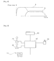
- Fig. 2 is a block diagram showing a configuration of a hydraulic system used in a traveling speed control method for a construction machine in accordance with a preferred embodiment of the present invention
- Fig. 3 is a flow chart showing a traveling speed control method for a construction machine in accordance with a preferred embodiment of the present invention
- Fig. 4 is a graph showing a discharge flow rate of hydraulic fluid discharged from a hydraulic pump when a working apparatus is manipulated during the traveling operation of a construction machine in a traveling speed control method for the construction machine in accordance with a preferred embodiment of the present invention.
- the present invention provides a traveling speed control method for a construction machine including a lower traveling structure, an upper swing structure mounted on the lower traveling structure so as to be swingable by a swing apparatus; a traveling apparatus mounted on the lower traveling structure, a working apparatus including a boom, an arm and a bucket, an electronic proportional valve configured to control a discharge flow rate of hydraulic fluid discharged from a hydraulic pump connected to an engine, and a controller.
- the traveling speed control method includes:
- a determination means can determine whether the traveling apparatus, the working apparatus, and the swing apparatus are manipulated based on a secondary pressure value that is output to the controller 40 by the manipulation of the hydraulic pedal 10 and the hydraulic joysticks 20 and 30. In this case, when at least any one of the hydraulic pedal 10 and the hydraulic joysticks 20 and 30 is an electric joystick, the determination means can determine whether the traveling apparatus, the working apparatus, and the swing apparatus are manipulated based on an electrical signal value that is output to the controller 40 by the manipulation of the hydraulic pedal 10 and the hydraulic joysticks 20 and 30.
- Any one of an on/off function switch, a potentiometer, a display device, and a cluster 60, which are installed in a cabin of the machine can be used as a setting means capable of reducing the separate maximum traveling speed of the traveling apparatus by the operator's setting.
- step S10 when the hydraulic pedal 10 is manipulated by the operator to allow an excavator to travel by an operator, a manipulation signal corresponding to a manipulation amount of the hydraulic pedal 10 is output to the controller 40.
- step S10A when the hydraulic joystick (e.g., RCV lever) 20 or 30 is manipulated by the operator so that the working apparatus or the swing apparatus can be driven, a manipulation signal (i.e., a secondary pressure value) corresponding to a manipulation amount of the hydraulic joystick 20 or 30 is output to the controller 40.
- a manipulation signal i.e., a secondary pressure value
- step S20 the controller 40 calculates a required flow rate of hydraulic fluid, which corresponds to the manipulation amount of the hydraulic pedal 10.
- step S20A the controller 40 respectively calculates the required flow rates of hydraulic fluid, which correspond to the manipulation amounts of the hydraulic joysticks 20 and 30.
- step S30 the controller 40 decreasingly re-calculates the required flow rate of hydraulic fluid of the traveling apparatus, which is calculated in the second step S20 in accordance with a ratio (for example, the ratio can be set by the operator to decrease the maximum traveling speed to 20%, 30%, 50%, etc.) set by an operator so that the separate maximum traveling speed of the traveling apparatus can be decreased by an operator's setting.
- a ratio for example, the ratio can be set by the operator to decrease the maximum traveling speed to 20%, 30%, 50%, etc.
- any one of an on/off function switch, a potentiometer, a display device, and a cluster 60 which are installed in the cabin of the machine so as to be manipulated by the operator may be used as a setting means capable of reducing the separate maximum traveling speed of the traveling apparatus by the operator's setting.
- a speed decreasing ratio is previously set in the cluster 60 so that the separate maximum traveling speed of the traveling apparatus can be decreased by the operator.
- the operator can select the speed decreasing ratio previously set in the cluster 60 to reduce the traveling speed
- step S40 controller 40 outputs an electrical control signal to the electronic proportional valve 50 so that the required flow rates of hydraulic fluid (i.e., the required flow rate of hydraulic fluid of the working apparatus and the reduced flow rate of hydraulic fluid of the traveling apparatus), which are calculated in the second and third steps S20A and S30, are combined and the combined flow rates of the hydraulic fluid is discharged from the hydraulic pump.
- a regulator of the hydraulic pump is driven by a secondary pressure generated to correspond to the electrical control signal that is input to the electronic proportional valve 50 so as to variably control a swivel angle of a swash plate of the hydraulic pump so that the discharge flow rate of hydraulic fluid from the hydraulic pump can be controlled.
- the separate maximum traveling speed of the traveling apparatus is decreased by the operator's setting so that the maximum traveling speed can be reduced even during the separate traveling of the machine.
- a sudden reduction in the traveling speed is prevented (see a curve "f" in a graph of Fig. 4 ) so that the occurrence of a traveling shock can be decreased, workability can be improved, and the operator's fatigue can be reduced.
- the separate maximum traveling speed is decreased by the operator's setting so that the discharge flow rate of hydraulic fluid discharged from the hydraulic pump can be reduced at an initial stage of the traveling operation (see a curve "d" in a graph of Fig. 4 ).
- only the traveling speed of the traveling apparatus is set to be decreased while constantly maintaining the driving speed of the working apparatus (see a curve "e” in a graph of Fig. 4 ) so that the traveling speed of traveling apparatus is set to a low speed while maintaining the driving speed of the working apparatus so that the engine's RPM need not to be adjusted to be lowered in order to reduce the traveling speed of the traveling apparatus.
- the separate maximum traveling speed of the traveling apparatus is set to a low speed so that when the working apparatus is manipulated during the traveling operation of the construction machine, a sudden change in the traveling speed can be prevented.
Landscapes
- Engineering & Computer Science (AREA)
- Mining & Mineral Resources (AREA)
- Civil Engineering (AREA)
- General Engineering & Computer Science (AREA)
- Structural Engineering (AREA)
- Operation Control Of Excavators (AREA)
Abstract
Disclosed is a method for controlling a driving speed of construction machinery for preventing a sudden change in the driving speed during a combined operation for operating a work device while driving an excavator. The method for controlling the driving speed of the construction machinery, according to one embodiment of the present invention, relates to the method for controlling the driving speed of the construction machinery comprising a lower driving body, a turning device for turning an upper turning body with respect to the lower driving body, a driving device, the work device, an electronic proportional valve for controlling the discharge flow rate of a hydraulic pump, and a controller. The method comprises: a first step of detecting the amount of operation of the driving device, the work device, and the turning device according to the operation of same; a second step of calculating a required working oil flow rate corresponding to the amount of operation of the driving device, the work device, and the turning device; a third step of reducing the required working oil flow rate of the driving device calculated in the second step, according to a ratio set by a driver, so that an independent maximum driving speed of the driving device can be reduced by the setting by the driver; and a fourth step of combining the required working oil flow rates calculated in the second step and the third step, and outputting a control signal to the electronic proportional valve so that the combined flow rate is discharged from the hydraulic pump..
Description
- The present invention relates to a traveling speed control method for a construction machinery. More particularly, the present invention relates to such a traveling speed control method for a construction machine in which when a combined operation is performed in which the working apparatus is manipulated during the separate traveling of the machine, a sudden change in the traveling speed is prevented.
-
Fig. 1 is a graph showing a discharge flow rate of hydraulic fluid discharged from a hydraulic pump when a working apparatus is manipulated during the traveling operation of the construction machine in accordance with the prior art. - In general, an excavator performs an excavation operation and the like by manipulating left and right traveling apparatuses and a working apparatus including a boom and the like. In the case where the traveling apparatus or the working apparatus is manipulated separately depending on the working conditions, a maximum flow rate of hydraulic fluid is discharged from the hydraulic pump, thereby increasing the working speed.
- Meanwhile, when a combined operation is performed in which the working apparatus is manipulated during a separate traveling of the machine, a maximum flow rate of hydraulic fluid (indicated by a curve "a" in a graph of
Fig. 1 ) discharged from the hydraulic pump is dispensively supplied to the traveling apparatus (indicated by a curve "c" in a graph ofFig. 1 ) or the working apparatus (indicated by a curve "d" in a graph ofFig. 1 ), thus leading to a remarkable decrease in the traveling speed. In addition, when the traveling apparatus and the working apparatus are manipulated simultaneously to cause the traveling speed to be remarkably decreased, there is caused a problem in that a traveling shock is induced due to a reduction in the traveling speed to weigh an operator's fatigue, and the work efficiency is deteriorated due to a difficulty of the work upon the combined operation of the machine. - Accordingly, the present invention has been made to solve the aforementioned problems occurring in the prior art, and it is an object of the present invention to provide a traveling speed control method for a construction machine, in which a separate maximum traveling speed of a traveling apparatus is set to a low speed so that when the working apparatus is manipulated during the traveling operation of the construction machine, a sudden change in the traveling speed can be prevented.
- To achieve the above object, in accordance with an embodiment of the present invention, there is provided a traveling speed control method for a construction machine including a lower traveling structure, a swing apparatus configured to swing an upper swing structure with respect to the lower traveling structure, a traveling apparatus, a working apparatus, an electronic proportional valve configured to control a discharge flow rate of hydraulic fluid discharged from a hydraulic pump, and a controller, the traveling speed control method including:
- a first step of detecting the manipulation amounts of the traveling apparatus, the working apparatus, and the swing apparatus according to the manipulation of the traveling apparatus, the working apparatus, and the swing apparatus;
- a second step of calculating required flow rates of hydraulic fluid, which correspond to the manipulation amounts of the traveling apparatus, the working apparatus, and the swing apparatus;
- a third step of decreasing the required flow rate of hydraulic fluid of the traveling apparatus, which is calculated in the second step in accordance with a ratio set by an operator so that a separate maximum traveling speed of the traveling apparatus can be decreased by an operator's setting; and
- a fourth step of outputting a control signal to the electronic proportional valve so that the required flow rates of hydraulic fluid, which are calculated in the second and third steps, are combined and the combined flow rates of the hydraulic fluid is discharged from the hydraulic pump.
- In the traveling speed control method, a determination means may determine whether the traveling apparatus, the working apparatus, and the swing apparatus are manipulated based on an electrical signal value that is output by the manipulation of an electric joystick or a secondary pressure value that is output by the manipulation of a hydraulic joystick.
- In the traveling speed control method, any one of an on/off function switch, a potentiometer, a display device, and a cluster, which are installed in a cabin of the machine, may be used as a setting means capable of reducing the separate maximum traveling speed of the traveling apparatus by the operator's setting.
- The traveling speed control method for a construction machine in accordance with an embodiment of the present invention as constructed above has the following advantages.
- The separate maximum traveling speed of the traveling apparatus is set to a low speed so that when the working apparatus is manipulated during the traveling operation of the construction machine, a traveling shock due to a sudden change in the traveling speed can be decreased, thereby reducing an operator's fatigue and improving workability.
- In addition, the traveling speed of traveling apparatus is set to a low speed while maintaining the driving speed of the working apparatus so that the engine's RPM need not to be adjusted to be lowered in order to reduce the traveling speed of the traveling apparatus.
- The above objects, other features and advantages of the present invention will become more apparent by describing the preferred embodiments thereof with reference to the accompanying drawings, in which:
-
Fig. 1 is a graph showing a discharge flow rate of hydraulic fluid discharged from a hydraulic pump when a working apparatus is manipulated during the traveling operation of the construction machine in accordance with the prior art; -
Fig. 2 is a block diagram showing a configuration of a hydraulic system used in a traveling speed control method for a construction machine in accordance with a preferred embodiment of the present invention; -
Fig. 3 is a flow chart showing a traveling speed control method for a construction machine in accordance with a preferred embodiment of the present invention; and -
Fig. 4 is a graph showing a discharge flow rate of hydraulic fluid discharged from a hydraulic pump when a working apparatus is manipulated during the traveling operation of a construction machine in a traveling speed control method for the construction machine in accordance with a preferred embodiment of the present invention. -
- 1: engine
- 10: hydraulic pedal
- 20, 30: hydraulic joystick
- 40: controller
- 50: electronic proportional valve
- 60: cluster
- Hereinafter, a traveling speed control method for a construction machine in accordance with a preferred embodiment of the present invention will be described in detail with reference to the accompanying drawings. The matters defined in the description, such as the detailed construction and elements, are nothing but specific details provided to assist those of ordinary skill in the art in a comprehensive understanding of the invention, and the present invention is not limited to the embodiments disclosed hereinafter.
- In order to definitely describe the present invention, a portion having no relevant to the description will be omitted, and through the specification, like elements are designated by like reference numerals.
- In the specification and the claims, when a portion includes an element, it is meant to include other elements, but not exclude the other elements unless otherwise specifically stated herein.
-
Fig. 2 is a block diagram showing a configuration of a hydraulic system used in a traveling speed control method for a construction machine in accordance with a preferred embodiment of the present invention,Fig. 3 is a flow chart showing a traveling speed control method for a construction machine in accordance with a preferred embodiment of the present invention, andFig. 4 is a graph showing a discharge flow rate of hydraulic fluid discharged from a hydraulic pump when a working apparatus is manipulated during the traveling operation of a construction machine in a traveling speed control method for the construction machine in accordance with a preferred embodiment of the present invention. - Referring to
Figs. 2 and3 , in accordance with a preferred embodiment of the present invention, the present invention provides a traveling speed control method for a construction machine including a lower traveling structure, an upper swing structure mounted on the lower traveling structure so as to be swingable by a swing apparatus; a traveling apparatus mounted on the lower traveling structure, a working apparatus including a boom, an arm and a bucket, an electronic proportional valve configured to control a discharge flow rate of hydraulic fluid discharged from a hydraulic pump connected to an engine, and a controller. The traveling speed control method includes: - a first step (S10, S10A) of outputting a manipulation signal corresponding to a manipulation amount of each of a
hydraulic pedal 10 andhydraulic joysticks hydraulic pedal 10 and thehydraulic joysticks - a second step (S20,S20A) of allowing the
controller 40 to respectively calculate required flow rates of hydraulic fluid, which correspond to the manipulation amounts of the traveling apparatus, the working apparatus, and the swing apparatus; - a third step (S30) of decreasingly re-calculating the required flow rate of hydraulic fluid of the traveling apparatus, which is calculated in the second step S20 in accordance with a ratio set by an operator so that a separate maximum traveling speed of the traveling apparatus can be decreased by an operator's setting; and
- a fourth step (S40) of outputting an electrical control signal to the electronic
proportional valve 50 so that the required flow rates of hydraulic fluid, which are calculated in the second and third steps S20, S20A and S30, are combined and the combined flow rates of the hydraulic fluid is discharged from the hydraulic pump (not shown). - A determination means can determine whether the traveling apparatus, the working apparatus, and the swing apparatus are manipulated based on a secondary pressure value that is output to the
controller 40 by the manipulation of thehydraulic pedal 10 and thehydraulic joysticks hydraulic pedal 10 and thehydraulic joysticks controller 40 by the manipulation of thehydraulic pedal 10 and thehydraulic joysticks - Any one of an on/off function switch, a potentiometer, a display device, and a
cluster 60, which are installed in a cabin of the machine can be used as a setting means capable of reducing the separate maximum traveling speed of the traveling apparatus by the operator's setting. - According to the configuration as described above, in step S10, when the
hydraulic pedal 10 is manipulated by the operator to allow an excavator to travel by an operator, a manipulation signal corresponding to a manipulation amount of thehydraulic pedal 10 is output to thecontroller 40. - In step S10A, when the hydraulic joystick (e.g., RCV lever) 20 or 30 is manipulated by the operator so that the working apparatus or the swing apparatus can be driven, a manipulation signal (i.e., a secondary pressure value) corresponding to a manipulation amount of the
hydraulic joystick controller 40. - In step S20, the
controller 40 calculates a required flow rate of hydraulic fluid, which corresponds to the manipulation amount of thehydraulic pedal 10. - In step S20A, the
controller 40 respectively calculates the required flow rates of hydraulic fluid, which correspond to the manipulation amounts of thehydraulic joysticks - In step S30, the
controller 40 decreasingly re-calculates the required flow rate of hydraulic fluid of the traveling apparatus, which is calculated in the second step S20 in accordance with a ratio (for example, the ratio can be set by the operator to decrease the maximum traveling speed to 20%, 30%, 50%, etc.) set by an operator so that the separate maximum traveling speed of the traveling apparatus can be decreased by an operator's setting. In this case, any one of an on/off function switch, a potentiometer, a display device, and acluster 60, which are installed in the cabin of the machine so as to be manipulated by the operator may be used as a setting means capable of reducing the separate maximum traveling speed of the traveling apparatus by the operator's setting. For example, a speed decreasing ratio is previously set in thecluster 60 so that the separate maximum traveling speed of the traveling apparatus can be decreased by the operator. Thus, the operator can select the speed decreasing ratio previously set in thecluster 60 to reduce the traveling speed during the traveling operation of the machine. - In step S40,
controller 40 outputs an electrical control signal to the electronicproportional valve 50 so that the required flow rates of hydraulic fluid (i.e., the required flow rate of hydraulic fluid of the working apparatus and the reduced flow rate of hydraulic fluid of the traveling apparatus), which are calculated in the second and third steps S20A and S30, are combined and the combined flow rates of the hydraulic fluid is discharged from the hydraulic pump. For this reason, a regulator of the hydraulic pump is driven by a secondary pressure generated to correspond to the electrical control signal that is input to the electronicproportional valve 50 so as to variably control a swivel angle of a swash plate of the hydraulic pump so that the discharge flow rate of hydraulic fluid from the hydraulic pump can be controlled. - As shown in a graph of
Fig. 4 , the separate maximum traveling speed of the traveling apparatus is decreased by the operator's setting so that the maximum traveling speed can be reduced even during the separate traveling of the machine. In addition, even in the case where a combined operation is performed in which the working apparatus is manipulated during the separate traveling of the machine, a sudden reduction in the traveling speed is prevented (see a curve "f" in a graph ofFig. 4 ) so that the occurrence of a traveling shock can be decreased, workability can be improved, and the operator's fatigue can be reduced. Further, the separate maximum traveling speed is decreased by the operator's setting so that the discharge flow rate of hydraulic fluid discharged from the hydraulic pump can be reduced at an initial stage of the traveling operation (see a curve "d" in a graph ofFig. 4 ). In addition, only the traveling speed of the traveling apparatus is set to be decreased while constantly maintaining the driving speed of the working apparatus (see a curve "e" in a graph ofFig. 4 ) so that the traveling speed of traveling apparatus is set to a low speed while maintaining the driving speed of the working apparatus so that the engine's RPM need not to be adjusted to be lowered in order to reduce the traveling speed of the traveling apparatus. - In accordance with the traveling speed control method for a construction machine of the present invention as constructed above, the separate maximum traveling speed of the traveling apparatus is set to a low speed so that when the working apparatus is manipulated during the traveling operation of the construction machine, a sudden change in the traveling speed can be prevented.
- While the present invention has been described in connection with the specific embodiments illustrated in the drawings, they are merely illustrative, and the invention is not limited to these embodiments. It is to be understood that various equivalent modifications and variations of the embodiments can be made by a person having an ordinary skill in the art without departing from the spirit and scope of the present invention. Therefore, the true technical scope of the present invention should not be defined by the above-mentioned embodiments but should be defined by the appended claims and equivalents thereof.
Claims (3)
- A traveling speed control method for a construction machine including a lower traveling structure, a swing apparatus configured to swing an upper swing structure with respect to the lower traveling structure, a traveling apparatus, a working apparatus, an electronic proportional valve configured to control a discharge flow rate of hydraulic fluid discharged from a hydraulic pump, and a controller, the traveling speed control method comprising:a first step of detecting the manipulation amounts of the traveling apparatus, the working apparatus, and the swing apparatus according to the manipulation of the traveling apparatus, the working apparatus, and the swing apparatus;a second step of calculating required flow rates of hydraulic fluid, which correspond to the manipulation amounts of the traveling apparatus, the working apparatus, and the swing apparatus;a third step of decreasing the required flow rate of hydraulic fluid of the traveling apparatus, which is calculated in the second step in accordance with a ratio set by an operator so that a separate maximum traveling speed of the traveling apparatus can be decreased by an operator's setting; anda fourth step of outputting a control signal to the electronic proportional valve so that the required flow rates of hydraulic fluid, which are calculated in the second and third steps, are combined and the combined flow rates of the hydraulic fluid is discharged from the hydraulic pump.
- The traveling speed control method according to claim 1, wherein a determination means determines whether the traveling apparatus, the working apparatus, and the swing apparatus are manipulated based on an electrical signal value that is output by the manipulation of an electric joystick or a secondary pressure value that is output by the manipulation of a hydraulic joystick.
- The traveling speed control method according to claim 1, wherein any one of an on/off function switch, a potentiometer, a display device, and a cluster, which are installed in a cabin of the machine is used as a setting means capable of reducing the separate maximum traveling speed of the traveling apparatus by the operator's setting.
Applications Claiming Priority (1)
| Application Number | Priority Date | Filing Date | Title |
|---|---|---|---|
| PCT/KR2013/000532 WO2014115905A1 (en) | 2013-01-23 | 2013-01-23 | Method for controlling driving speed of construction machinery |
Publications (1)
| Publication Number | Publication Date |
|---|---|
| EP2949820A1 true EP2949820A1 (en) | 2015-12-02 |
Family
ID=51227690
Family Applications (1)
| Application Number | Title | Priority Date | Filing Date |
|---|---|---|---|
| EP13873027.0A Withdrawn EP2949820A1 (en) | 2013-01-23 | 2013-01-23 | Method for controlling driving speed of construction machinery |
Country Status (5)
| Country | Link |
|---|---|
| US (1) | US20150354174A1 (en) |
| EP (1) | EP2949820A1 (en) |
| KR (1) | KR20150105961A (en) |
| CN (1) | CN104937179A (en) |
| WO (1) | WO2014115905A1 (en) |
Cited By (2)
| Publication number | Priority date | Publication date | Assignee | Title |
|---|---|---|---|---|
| EP3228760A1 (en) * | 2016-04-08 | 2017-10-11 | Caterpillar Inc. | Travel control system and method for a work machine |
| CN107747331A (en) * | 2017-05-03 | 2018-03-02 | 柳州柳工挖掘机有限公司 | Crawler-mounted excavator auto-manual walking hydra-electric system |
Families Citing this family (5)
| Publication number | Priority date | Publication date | Assignee | Title |
|---|---|---|---|---|
| CN104956006B (en) * | 2012-12-13 | 2017-10-03 | 现代建设机械(株) | For the automatic control system and method for the Architectural Equipment controlled based on control stick |
| KR101741703B1 (en) * | 2013-01-24 | 2017-05-30 | 볼보 컨스트럭션 이큅먼트 에이비 | Device and method for controlling flow rate in construction machinery |
| KR101822931B1 (en) * | 2013-02-06 | 2018-01-29 | 볼보 컨스트럭션 이큅먼트 에이비 | Swing Control System For Construction Machines |
| KR102471489B1 (en) | 2015-07-15 | 2022-11-28 | 현대두산인프라코어(주) | A construction machinery and method for the construction machinery |
| EP3724409A4 (en) * | 2017-12-14 | 2022-01-12 | Volvo Construction Equipment AB | Hydraulic machine |
Family Cites Families (5)
| Publication number | Priority date | Publication date | Assignee | Title |
|---|---|---|---|---|
| KR100493358B1 (en) * | 1997-12-30 | 2005-08-17 | 볼보 컨스트럭션 이키프먼트 홀딩 스웨덴 에이비 | Heavy Duty Driving Device |
| US7757486B2 (en) * | 2004-09-27 | 2010-07-20 | Hitachi Construction Machinery Co., Ltd. | Engine control device for work vehicle |
| KR100611714B1 (en) * | 2005-02-17 | 2006-08-11 | 볼보 컨스트럭션 이키프먼트 홀딩 스웨덴 에이비 | A method and apparatus for shock absorbing of heavy equipment in urgent return |
| KR100621985B1 (en) * | 2005-08-02 | 2006-09-11 | 볼보 컨스트럭션 이키프먼트 홀딩 스웨덴 에이비 | System for driving |
| KR100974279B1 (en) * | 2008-03-27 | 2010-08-06 | 볼보 컨스트럭션 이키프먼트 홀딩 스웨덴 에이비 | travel system for heavy equipment |
-
2013
- 2013-01-23 WO PCT/KR2013/000532 patent/WO2014115905A1/en active Application Filing
- 2013-01-23 US US14/762,315 patent/US20150354174A1/en not_active Abandoned
- 2013-01-23 KR KR1020157019831A patent/KR20150105961A/en not_active Application Discontinuation
- 2013-01-23 EP EP13873027.0A patent/EP2949820A1/en not_active Withdrawn
- 2013-01-23 CN CN201380071263.5A patent/CN104937179A/en active Pending
Non-Patent Citations (1)
| Title |
|---|
| See references of WO2014115905A1 * |
Cited By (3)
| Publication number | Priority date | Publication date | Assignee | Title |
|---|---|---|---|---|
| EP3228760A1 (en) * | 2016-04-08 | 2017-10-11 | Caterpillar Inc. | Travel control system and method for a work machine |
| US10323389B2 (en) | 2016-04-08 | 2019-06-18 | Caterpillar Inc. | Control system and method for a machine |
| CN107747331A (en) * | 2017-05-03 | 2018-03-02 | 柳州柳工挖掘机有限公司 | Crawler-mounted excavator auto-manual walking hydra-electric system |
Also Published As
| Publication number | Publication date |
|---|---|
| CN104937179A (en) | 2015-09-23 |
| KR20150105961A (en) | 2015-09-18 |
| WO2014115905A1 (en) | 2014-07-31 |
| US20150354174A1 (en) | 2015-12-10 |
Similar Documents
| Publication | Publication Date | Title |
|---|---|---|
| EP2949820A1 (en) | Method for controlling driving speed of construction machinery | |
| US8146355B2 (en) | Traveling device for crawler type heavy equipment | |
| US20130160439A1 (en) | Flow rate control device for variable displacement type hydraulic pump for construction equipment | |
| EP2600010A1 (en) | Swirl flow control system for construction equipment and method of controlling the same | |
| US9920780B2 (en) | Slewing drive apparatus for construction machine | |
| WO2016136229A1 (en) | Hydraulic drive system for construction equipment | |
| KR20130124161A (en) | System for controlling hydraulic pump in construction machine | |
| EP2660478A1 (en) | Boom-swivel compound drive hydraulic control system of construction machine | |
| CN110392789B (en) | Excavator | |
| US20150204359A1 (en) | Construction machine | |
| US20150322648A1 (en) | Device and method for controlling flow rate in construction machinery | |
| KR102156447B1 (en) | Hydraulic system of construction machinery | |
| US9909281B2 (en) | Construction machine | |
| KR20110074367A (en) | Hydraulic control apparatus for construction machinery | |
| JP5816216B2 (en) | Pump controller for construction machinery | |
| KR102461096B1 (en) | Method and apparatus for controlling travelling speed of construction machinery | |
| KR101744709B1 (en) | Engine speed controller of work machine | |
| EP2937470A1 (en) | Automatic transmission control unit for construction equipment and control method therefor | |
| WO2016157531A1 (en) | Hydraulic control device for operating machine | |
| WO2013089230A1 (en) | Hydraulic machinery | |
| JP2014190514A (en) | Pump control device for construction machine | |
| US9725885B2 (en) | Hydraulic construction machinery | |
| CN107208398B (en) | Method for compensating the hydraulic pump flow of a construction machine | |
| US20160319517A1 (en) | Constant Net Implement Pump Valve Flow | |
| JP2016200241A (en) | Hydraulic pressure control system and construction machine |
Legal Events
| Date | Code | Title | Description |
|---|---|---|---|
| PUAI | Public reference made under article 153(3) epc to a published international application that has entered the european phase |
Free format text: ORIGINAL CODE: 0009012 |
|
| 17P | Request for examination filed |
Effective date: 20150723 |
|
| AK | Designated contracting states |
Kind code of ref document: A1 Designated state(s): AL AT BE BG CH CY CZ DE DK EE ES FI FR GB GR HR HU IE IS IT LI LT LU LV MC MK MT NL NO PL PT RO RS SE SI SK SM TR |
|
| AX | Request for extension of the european patent |
Extension state: BA ME |
|
| DAX | Request for extension of the european patent (deleted) | ||
| STAA | Information on the status of an ep patent application or granted ep patent |
Free format text: STATUS: THE APPLICATION HAS BEEN WITHDRAWN |
|
| 18W | Application withdrawn |
Effective date: 20160615 |