EP2949507A1 - Vehicle and method of controlling a vehicle - Google Patents
Vehicle and method of controlling a vehicle Download PDFInfo
- Publication number
- EP2949507A1 EP2949507A1 EP14170504.6A EP14170504A EP2949507A1 EP 2949507 A1 EP2949507 A1 EP 2949507A1 EP 14170504 A EP14170504 A EP 14170504A EP 2949507 A1 EP2949507 A1 EP 2949507A1
- Authority
- EP
- European Patent Office
- Prior art keywords
- vehicle
- material discharge
- inter
- axle differential
- transmission
- Prior art date
- Legal status (The legal status is an assumption and is not a legal conclusion. Google has not performed a legal analysis and makes no representation as to the accuracy of the status listed.)
- Withdrawn
Links
- 238000000034 method Methods 0.000 title claims abstract description 12
- 230000007246 mechanism Effects 0.000 claims abstract description 58
- 239000000463 material Substances 0.000 claims abstract description 44
- 230000005540 biological transmission Effects 0.000 claims abstract description 30
- 230000007935 neutral effect Effects 0.000 claims abstract description 18
- 230000004913 activation Effects 0.000 claims abstract description 8
- 230000008878 coupling Effects 0.000 description 7
- 238000010168 coupling process Methods 0.000 description 7
- 238000005859 coupling reaction Methods 0.000 description 7
- 238000009412 basement excavation Methods 0.000 description 1
- 238000002485 combustion reaction Methods 0.000 description 1
- 238000010276 construction Methods 0.000 description 1
- 230000009189 diving Effects 0.000 description 1
- 230000000694 effects Effects 0.000 description 1
- 239000012530 fluid Substances 0.000 description 1
- 230000005484 gravity Effects 0.000 description 1
- 230000003068 static effect Effects 0.000 description 1
Images

Classifications
-
- B—PERFORMING OPERATIONS; TRANSPORTING
- B60—VEHICLES IN GENERAL
- B60P—VEHICLES ADAPTED FOR LOAD TRANSPORTATION OR TO TRANSPORT, TO CARRY, OR TO COMPRISE SPECIAL LOADS OR OBJECTS
- B60P1/00—Vehicles predominantly for transporting loads and modified to facilitate loading, consolidating the load, or unloading
- B60P1/04—Vehicles predominantly for transporting loads and modified to facilitate loading, consolidating the load, or unloading with a tipping movement of load-transporting element
- B60P1/045—Levelling or stabilising systems for tippers
-
- B—PERFORMING OPERATIONS; TRANSPORTING
- B60—VEHICLES IN GENERAL
- B60K—ARRANGEMENT OR MOUNTING OF PROPULSION UNITS OR OF TRANSMISSIONS IN VEHICLES; ARRANGEMENT OR MOUNTING OF PLURAL DIVERSE PRIME-MOVERS IN VEHICLES; AUXILIARY DRIVES FOR VEHICLES; INSTRUMENTATION OR DASHBOARDS FOR VEHICLES; ARRANGEMENTS IN CONNECTION WITH COOLING, AIR INTAKE, GAS EXHAUST OR FUEL SUPPLY OF PROPULSION UNITS IN VEHICLES
- B60K17/00—Arrangement or mounting of transmissions in vehicles
- B60K17/34—Arrangement or mounting of transmissions in vehicles for driving both front and rear wheels, e.g. four wheel drive vehicles
- B60K17/348—Arrangement or mounting of transmissions in vehicles for driving both front and rear wheels, e.g. four wheel drive vehicles having differential means for driving one set of wheels, e.g. the front, at one speed and the other set, e.g. the rear, at a different speed
-
- B—PERFORMING OPERATIONS; TRANSPORTING
- B60—VEHICLES IN GENERAL
- B60K—ARRANGEMENT OR MOUNTING OF PROPULSION UNITS OR OF TRANSMISSIONS IN VEHICLES; ARRANGEMENT OR MOUNTING OF PLURAL DIVERSE PRIME-MOVERS IN VEHICLES; AUXILIARY DRIVES FOR VEHICLES; INSTRUMENTATION OR DASHBOARDS FOR VEHICLES; ARRANGEMENTS IN CONNECTION WITH COOLING, AIR INTAKE, GAS EXHAUST OR FUEL SUPPLY OF PROPULSION UNITS IN VEHICLES
- B60K23/00—Arrangement or mounting of control devices for vehicle transmissions, or parts thereof, not otherwise provided for
- B60K23/04—Arrangement or mounting of control devices for vehicle transmissions, or parts thereof, not otherwise provided for for differential gearing
-
- B—PERFORMING OPERATIONS; TRANSPORTING
- B60—VEHICLES IN GENERAL
- B60P—VEHICLES ADAPTED FOR LOAD TRANSPORTATION OR TO TRANSPORT, TO CARRY, OR TO COMPRISE SPECIAL LOADS OR OBJECTS
- B60P1/00—Vehicles predominantly for transporting loads and modified to facilitate loading, consolidating the load, or unloading
- B60P1/04—Vehicles predominantly for transporting loads and modified to facilitate loading, consolidating the load, or unloading with a tipping movement of load-transporting element
- B60P1/28—Tipping body constructions
- B60P1/283—Elements of tipping devices
-
- B—PERFORMING OPERATIONS; TRANSPORTING
- B60—VEHICLES IN GENERAL
- B60T—VEHICLE BRAKE CONTROL SYSTEMS OR PARTS THEREOF; BRAKE CONTROL SYSTEMS OR PARTS THEREOF, IN GENERAL; ARRANGEMENT OF BRAKING ELEMENTS ON VEHICLES IN GENERAL; PORTABLE DEVICES FOR PREVENTING UNWANTED MOVEMENT OF VEHICLES; VEHICLE MODIFICATIONS TO FACILITATE COOLING OF BRAKES
- B60T7/00—Brake-action initiating means
- B60T7/12—Brake-action initiating means for automatic initiation; for initiation not subject to will of driver or passenger
- B60T7/20—Brake-action initiating means for automatic initiation; for initiation not subject to will of driver or passenger specially for trailers, e.g. in case of uncoupling of or overrunning by trailer
-
- B—PERFORMING OPERATIONS; TRANSPORTING
- B60—VEHICLES IN GENERAL
- B60W—CONJOINT CONTROL OF VEHICLE SUB-UNITS OF DIFFERENT TYPE OR DIFFERENT FUNCTION; CONTROL SYSTEMS SPECIALLY ADAPTED FOR HYBRID VEHICLES; ROAD VEHICLE DRIVE CONTROL SYSTEMS FOR PURPOSES NOT RELATED TO THE CONTROL OF A PARTICULAR SUB-UNIT
- B60W10/00—Conjoint control of vehicle sub-units of different type or different function
- B60W10/12—Conjoint control of vehicle sub-units of different type or different function including control of differentials
- B60W10/14—Central differentials for dividing torque between front and rear axles
-
- B—PERFORMING OPERATIONS; TRANSPORTING
- B60—VEHICLES IN GENERAL
- B60W—CONJOINT CONTROL OF VEHICLE SUB-UNITS OF DIFFERENT TYPE OR DIFFERENT FUNCTION; CONTROL SYSTEMS SPECIALLY ADAPTED FOR HYBRID VEHICLES; ROAD VEHICLE DRIVE CONTROL SYSTEMS FOR PURPOSES NOT RELATED TO THE CONTROL OF A PARTICULAR SUB-UNIT
- B60W10/00—Conjoint control of vehicle sub-units of different type or different function
- B60W10/18—Conjoint control of vehicle sub-units of different type or different function including control of braking systems
- B60W10/182—Conjoint control of vehicle sub-units of different type or different function including control of braking systems including control of parking brakes
-
- B—PERFORMING OPERATIONS; TRANSPORTING
- B60—VEHICLES IN GENERAL
- B60W—CONJOINT CONTROL OF VEHICLE SUB-UNITS OF DIFFERENT TYPE OR DIFFERENT FUNCTION; CONTROL SYSTEMS SPECIALLY ADAPTED FOR HYBRID VEHICLES; ROAD VEHICLE DRIVE CONTROL SYSTEMS FOR PURPOSES NOT RELATED TO THE CONTROL OF A PARTICULAR SUB-UNIT
- B60W10/00—Conjoint control of vehicle sub-units of different type or different function
- B60W10/18—Conjoint control of vehicle sub-units of different type or different function including control of braking systems
- B60W10/184—Conjoint control of vehicle sub-units of different type or different function including control of braking systems with wheel brakes
-
- B—PERFORMING OPERATIONS; TRANSPORTING
- B60—VEHICLES IN GENERAL
- B60W—CONJOINT CONTROL OF VEHICLE SUB-UNITS OF DIFFERENT TYPE OR DIFFERENT FUNCTION; CONTROL SYSTEMS SPECIALLY ADAPTED FOR HYBRID VEHICLES; ROAD VEHICLE DRIVE CONTROL SYSTEMS FOR PURPOSES NOT RELATED TO THE CONTROL OF A PARTICULAR SUB-UNIT
- B60W30/00—Purposes of road vehicle drive control systems not related to the control of a particular sub-unit, e.g. of systems using conjoint control of vehicle sub-units
- B60W30/18—Propelling the vehicle
- B60W30/18009—Propelling the vehicle related to particular drive situations
- B60W30/18054—Propelling the vehicle related to particular drive situations at stand still, e.g. engine in idling state
-
- F—MECHANICAL ENGINEERING; LIGHTING; HEATING; WEAPONS; BLASTING
- F16—ENGINEERING ELEMENTS AND UNITS; GENERAL MEASURES FOR PRODUCING AND MAINTAINING EFFECTIVE FUNCTIONING OF MACHINES OR INSTALLATIONS; THERMAL INSULATION IN GENERAL
- F16H—GEARING
- F16H48/00—Differential gearings
- F16H48/20—Arrangements for suppressing or influencing the differential action, e.g. locking devices
- F16H48/30—Arrangements for suppressing or influencing the differential action, e.g. locking devices using externally-actuatable means
- F16H48/32—Arrangements for suppressing or influencing the differential action, e.g. locking devices using externally-actuatable means using fluid pressure actuators
-
- B—PERFORMING OPERATIONS; TRANSPORTING
- B60—VEHICLES IN GENERAL
- B60K—ARRANGEMENT OR MOUNTING OF PROPULSION UNITS OR OF TRANSMISSIONS IN VEHICLES; ARRANGEMENT OR MOUNTING OF PLURAL DIVERSE PRIME-MOVERS IN VEHICLES; AUXILIARY DRIVES FOR VEHICLES; INSTRUMENTATION OR DASHBOARDS FOR VEHICLES; ARRANGEMENTS IN CONNECTION WITH COOLING, AIR INTAKE, GAS EXHAUST OR FUEL SUPPLY OF PROPULSION UNITS IN VEHICLES
- B60K23/00—Arrangement or mounting of control devices for vehicle transmissions, or parts thereof, not otherwise provided for
- B60K23/04—Arrangement or mounting of control devices for vehicle transmissions, or parts thereof, not otherwise provided for for differential gearing
- B60K2023/046—Axle differential locking means
-
- B—PERFORMING OPERATIONS; TRANSPORTING
- B60—VEHICLES IN GENERAL
- B60W—CONJOINT CONTROL OF VEHICLE SUB-UNITS OF DIFFERENT TYPE OR DIFFERENT FUNCTION; CONTROL SYSTEMS SPECIALLY ADAPTED FOR HYBRID VEHICLES; ROAD VEHICLE DRIVE CONTROL SYSTEMS FOR PURPOSES NOT RELATED TO THE CONTROL OF A PARTICULAR SUB-UNIT
- B60W2510/00—Input parameters relating to a particular sub-units
- B60W2510/10—Change speed gearings
- B60W2510/1005—Transmission ratio engaged
- B60W2510/101—Transmission neutral state
-
- B—PERFORMING OPERATIONS; TRANSPORTING
- B60—VEHICLES IN GENERAL
- B60W—CONJOINT CONTROL OF VEHICLE SUB-UNITS OF DIFFERENT TYPE OR DIFFERENT FUNCTION; CONTROL SYSTEMS SPECIALLY ADAPTED FOR HYBRID VEHICLES; ROAD VEHICLE DRIVE CONTROL SYSTEMS FOR PURPOSES NOT RELATED TO THE CONTROL OF A PARTICULAR SUB-UNIT
- B60W2520/00—Input parameters relating to overall vehicle dynamics
- B60W2520/04—Vehicle stop
-
- B—PERFORMING OPERATIONS; TRANSPORTING
- B60—VEHICLES IN GENERAL
- B60W—CONJOINT CONTROL OF VEHICLE SUB-UNITS OF DIFFERENT TYPE OR DIFFERENT FUNCTION; CONTROL SYSTEMS SPECIALLY ADAPTED FOR HYBRID VEHICLES; ROAD VEHICLE DRIVE CONTROL SYSTEMS FOR PURPOSES NOT RELATED TO THE CONTROL OF A PARTICULAR SUB-UNIT
- B60W2710/00—Output or target parameters relating to a particular sub-units
- B60W2710/12—Differentials
- B60W2710/125—Locking status
-
- B—PERFORMING OPERATIONS; TRANSPORTING
- B60—VEHICLES IN GENERAL
- B60W—CONJOINT CONTROL OF VEHICLE SUB-UNITS OF DIFFERENT TYPE OR DIFFERENT FUNCTION; CONTROL SYSTEMS SPECIALLY ADAPTED FOR HYBRID VEHICLES; ROAD VEHICLE DRIVE CONTROL SYSTEMS FOR PURPOSES NOT RELATED TO THE CONTROL OF A PARTICULAR SUB-UNIT
- B60W2710/00—Output or target parameters relating to a particular sub-units
- B60W2710/18—Braking system
- B60W2710/186—Status of parking brakes
-
- B—PERFORMING OPERATIONS; TRANSPORTING
- B60—VEHICLES IN GENERAL
- B60Y—INDEXING SCHEME RELATING TO ASPECTS CROSS-CUTTING VEHICLE TECHNOLOGY
- B60Y2200/00—Type of vehicle
- B60Y2200/10—Road Vehicles
- B60Y2200/14—Trucks; Load vehicles, Busses
- B60Y2200/142—Heavy duty trucks
- B60Y2200/1422—Multi-axle trucks
-
- B—PERFORMING OPERATIONS; TRANSPORTING
- B60—VEHICLES IN GENERAL
- B60Y—INDEXING SCHEME RELATING TO ASPECTS CROSS-CUTTING VEHICLE TECHNOLOGY
- B60Y2200/00—Type of vehicle
- B60Y2200/40—Special vehicles
- B60Y2200/41—Construction vehicles, e.g. graders, excavators
- B60Y2200/415—Wheel loaders
Definitions
- the present disclosure relates generally to a vehicle and a method of controlling a vehicle which has a material discharge mechanism, such as a tipping or ejection mechanism.
- Load carrying vehicles including trucks, wheel loaders and the like, are commonly employed during construction and excavation for transporting loads from one point to another.
- Articulated vehicles including articulated trucks with tipping bodies, articulated trucks with ejector mechanisms, articulated wheel loaders and the like, typically comprise a first frame (such as a tractor) and a second frame (such as a trailer) connected to one another via an articulation joint.
- the articulation joint enables the frames to roll relative to one another.
- Load carrying vehicles may also comprise a member such as a payload carrier for holding material.
- the payload carrier may be configured to be tipped about a pivot point to empty any material held therein.
- Ejector mechanisms are well known in the art, and typically comprise an ejector plate which slides horizontally from one end of the inside of the payload carrier towards the other end (the ejection end) to push any load or materials out of the payload carrier.
- Tipping systems and ejection systems are examples of material discharge systems.
- the present disclosure therefore provides a vehicle comprising:
- the present disclosure further provides a method of controlling a vehicle, said vehicle comprising:
- the method of the present disclosure may be used in any vehicle, in particular a load carrying vehicle, which has a payload carrier and a plurality of axles.
- Such vehicles include articulated or non-articulated vehicles.
- One exemplary vehicle 10 is illustrated in Figure 1 in the form of an articulated tipper truck.
- the vehicle 10 may comprise a first frame 11, in this example a tractor unit, attached to a second frame 12, in this example a trailer unit.
- the frames 11, 12 may be attached together by a coupling 13.
- the first frame 11 may comprise an operator cab 14 which houses the operator controls for the vehicle 10.
- the controls may include one or more brake actuators (such as pedals), a transmission gear select lever, one or more levers (such as a hoist lever for operating the vehicle's working equipment) and a steering device.
- the transmission gear select lever and hoist lever(s) may be combined into a single select lever.
- the coupling 13 which may be an articulation joint, may allow each of the first and second frames 11, 12 to be orientated at a different yaw and/or roll angle to the other frame 12, 11.
- the vehicle 10 may be steered by adjusting the yaw angle of the first and second frames 11, 12 about an axis of articulation 15 utilising actuators, for example hydraulic cylinders, suitably attached to each of the first and second frames 11, 12 on either side of the coupling 13.
- the coupling 13 may allow the first and second frames 11, 12 to freely rotate about a roll axis 16 relative to one another.
- the second frame 12 may comprise a payload carrier 17, such as a dump body adapted to carry a load which is pivotally attached to a chassis 18 of the first frame 11 at a pivot point.
- the second frame 12 may comprise a material discharge mechanism in the form of a tipping system which, when activated, causes the payload carrier 17 to rotate about the pivot from a "body down" position 19 into a "body up” tipping position 20.
- the tipping system may be any suitable system, such as, for example, a hydraulic, electric or mechanical system. As the tipping system rotates the payload carrier 17 to the body up tipping position 20, the payload carrier 17 ejects any materials or load from the payload carrier 17.
- the payload carrier 17 may be any type of container and may be open at the top, fully enclosed or partially enclosed.
- the vehicle may have a material discharge mechanism in the form of an ejector mechanism.
- Ejector mechanisms are well known in the art, and typically comprise an ejector plate which slides horizontally from one end of the inside of the payload carrier 17 towards the other end (the ejection end) to push any load or materials out of the payload carrier 17.
- a hydraulic actuator or the like may be used to move the ejector plate towards the ejection end of the payload carrier 17.
- the material discharge mechanism may be activated by an operator controlled material discharge mechanism selection lever located in the operator cab 14. Operation of the lever may provide a material discharge request to the control system.
- the vehicle may further comprise a power unit 25, which may be an internal combustion engine, a micro-turbine, an electric motor or any other suitable unit, which provides a power output which may be used to drive the vehicle 10 and operate the material discharge mechanism and other of the venicle's systems.
- a power unit 25 which may be an internal combustion engine, a micro-turbine, an electric motor or any other suitable unit, which provides a power output which may be used to drive the vehicle 10 and operate the material discharge mechanism and other of the venicle's systems.
- the vehicle 10 may comprise one or more terrain engaging means 21,22 in contact with the terrain 23.
- the terrain 23 may be the ground or any surface on which the load carrying vehicle 10 is operated.
- the terrain engaging means 21,22 may be, for example, tracks and/or wheels which enable the vehicle 10 to move along the terrain 23 and the vehicle 10 may comprise any number of terrain engaging means 22.
- the first frame 11 may have one pair of first frame ground engaging means 22 and the second frame 12 may have two pairs second frame ground engaging means 21, with one of each pair of ground engaging means 21,22 located on either side of the vehicle 10.
- the vehicle 10 may further comprise a drive train, which may include a transmission 24 which is operated by the transmission gear select lever and enables to the operator to select an appropriate gear or transmission mode for the operation of the vehicle 10.
- the transmission modes may include a neutral mode, in which the gear trains within the transmission 24 are disconnected, and one or more drive modes, such as forward (which allows the gear ratio to change automatically), reverse or one or more specific gears.
- the drive train may couple the power unit 25 to drive at least one of the terrain engaging means 21,22 to move the vehicle 10 along the terrain 23.
- the drive train may comprise a plurality of axles 26,27 connecting the pairs of terrain engaging means 21,22.
- a first frame axle 27 may connect the pair of first frame ground engaging means 22 and a second frame axle 26 connects each member of the pairs of second frame ground engaging means 22.
- the axles 26,27 may be connected to, and driven by, the power unit 25 as described below.
- the power unit 25 may be mounted on the first frame 11 and the drive train may further comprise a torque transfer arrangement 30 for transferring torque from the power unit 25 to the first frame terrain engaging means.
- the transmission 24 may be coupled to receive torque from the power unit 25.
- the transmission 24 may have an output drive coupling 28 for providing the torque.
- the torque transfer arrangement 30 may include gearing 31, which may comprise a plurality of gears, a plurality of drive shafts, which may include a first frame drive shaft 33 and a second frame drive shaft 32, and an inter-axle differential which is an integral part of the gearing 31.
- the drive shafts 32,33 may each be connected to at least one of the plurality of gears 31 and may be adapted to receive a percentage of the torque and transmit the torque to the first and second frame axles 26,27.
- the inter-axle differential may be drivably connected to the coupling 28 to receive torque and provide the torque to more than one of the plurality of gears 31.
- An inter-axle differential splits the input shaft torque between the first and second frame axles 26,27.
- the inter-axle differential may be provided with an inter-axle differential lock.
- the inter-axle differential lock may lock the first frame and second frame axles 26,27 together so that they rotate together at the same speed thereby driving the ground engaging means 21,22 at the same speed.
- the inter-axle differential lock may be actuated by pressurized hydraulic fluid supplied from a differential control valve.
- the inter-axle differential lock may have a manual mode, in which it is engaged or disengaged by the vehicle operator, for example by operation of a switch.
- the inter-axle differential lock may also have an automatic mode, in which it is engaged or disengaged by the vehicle control system.
- the vehicle 10 may also be provided with one or more brake mechanisms 29.
- the brake mechanism(s) 29 may include parking brakes, which are intended for use when the power unit 25 is not running and the vehicle 10 is not being operated. In such situations the vehicle 10 may be brought to a halt on level ground, the parking brakes engaged and the power unit 25 switched off.
- the brake mechanism(s) 29 may also include service brakes for situations in which the load carrying vehicle 10 may be stopped temporarily with the power unit 25 still running, such as during loading and dumping.
- the service brakes may be activated by the operator via a foot pedal.
- the brake mechanism(s) 29 may also have an automatic mode, in which one or both are engaged or disengaged by the control system.
- the vehicle 10 may comprise a control system, which may comprise one or more electronic control units (ECUs) which have the ability to monitor operating parameters and to control operation of the power unit 25, the brake mechanism(s) 29, the inter-axle differential lock and other elements of the vehicle 10.
- the control system may use software to provide control logic for the automatic engagement of the inter-axle differential lock and one or more of the brake mechanisms 29 when certain conditions are met. These conditions may include that the vehicle 10 is substantially stationery, for example moving at a speed of less than lmph, that the transmission is in neutral and a material discharge request has been given.
- the control system may also increase the speed of the power unit 25.
- the control system may also automatically disengage the inter-axle differential lock and the brake mechanism(s) 29 when the transmission is placed in a drive mode.
- the control system is suitable for use with a variety of vehicles 10 and in particular load carrying vehicles including a material discharge mechanism. However, the control system is particularly suited to articulated vehicles.
- the operator When the operator wishes to unload the vehicle 10, he may bring the vehicle to a halt, which may be by means of the vehicle's service brakes.
- the operator When the vehicle is stationary, the operator may select neutral transmission mode, for example by means of the transmission gear select lever. The operator may then activate the material discharge mechanism selection lever to request operation the material discharge system.
- the control system determines that a material discharge request has been given, if it also determines that the vehicle 10 is substantially stationery and that the transmission is in neutral mode, it may automatically engage the inter-axle differential lock and one or more of the brake mechanisms 29 and actuate the material discharge function. It may also increase the speed of the power unit 25.
- the control system may automatically engage the inter-axle differential lock but not engage one or more of the brake mechanisms 29. Instead it will only activate the material discharge system. This enables the operator to discharge the material in an even layer by tipping/ejecting whilst diving forward.
- the operator may select a drive mode (forward or reverse), for example by means of the transmission gear select lever before moving off.
- a drive mode forward or reverse
- the control system automatically disengages the inter-axle differential lock and the brake mechanism(s) 29 to allow the vehicle 10 to move off.
- the control system may therefore enable the automatic synchronisation of the operation of the inter-axle differential lock and the brake mechanism(s) 29 with operation of the material discharge mechanism to enable the operator to focus on driving the vehicle 10. This may optimise material discharge time and thereby improve productivity.
- the control system may also improve vehicle stability by ensuring that the drive train is locked during static unloading events. By applying the inter-axle differential lock and brake mechanism(s), the driveline is locked up. This may have the effect of preventing relative rotation through the coupling 13. If the first frame 11 is prevented from rotating relative to the second frame 12, if the first frame 11 rises off the ground, it stays in the same orientation as the second frame 12 and may not roll onto the ground.
Landscapes
- Engineering & Computer Science (AREA)
- Mechanical Engineering (AREA)
- Transportation (AREA)
- Chemical & Material Sciences (AREA)
- Combustion & Propulsion (AREA)
- General Engineering & Computer Science (AREA)
- Physics & Mathematics (AREA)
- Analytical Chemistry (AREA)
- Fluid Mechanics (AREA)
- Automation & Control Theory (AREA)
- Retarders (AREA)
- Arrangement And Driving Of Transmission Devices (AREA)
Abstract
Description
- The present disclosure relates generally to a vehicle and a method of controlling a vehicle which has a material discharge mechanism, such as a tipping or ejection mechanism.
- Load carrying vehicles, including trucks, wheel loaders and the like, are commonly employed during construction and excavation for transporting loads from one point to another.
- Articulated vehicles, including articulated trucks with tipping bodies, articulated trucks with ejector mechanisms, articulated wheel loaders and the like, typically comprise a first frame (such as a tractor) and a second frame (such as a trailer) connected to one another via an articulation joint. The articulation joint enables the frames to roll relative to one another.
- Load carrying vehicles may also comprise a member such as a payload carrier for holding material. The payload carrier may be configured to be tipped about a pivot point to empty any material held therein.
- Alternatively in order for the load or materials to be ejected from the payload carrier, it may not be designed to move relative to the chassis, but may instead utilise an ejector mechanism. Ejector mechanisms are well known in the art, and typically comprise an ejector plate which slides horizontally from one end of the inside of the payload carrier towards the other end (the ejection end) to push any load or materials out of the payload carrier.
- Tipping systems and ejection systems are examples of material discharge systems.
- One problem which may occur with articulated vehicles is if the tractor lifts off the ground, the articulation joint between the tractor and trailer allows the tractor to rotate (roll) relative to the trailer. The result being that the tractor may roll onto its side (the ground) causing damage to the tractor. This may occur during tipping if the ground gives way under the trailer axles, as this can cause the tractor to rise off the ground. Whilst tipping on steep grades, if material gets stuck in the payload carrier and then starts to move, the rapid change in the centre of gravity of the load may also cause the tractor to rise off the ground.
- The present disclosure therefore provides a vehicle comprising:
- a material discharge mechanism;
- a plurality of axles;
- an inter-axle differential connecting the plurality of axles;
- a transmission having at least one drive mode and a neutral mode;
- at least one brake mechanism; and
- a control system, said control system being configured to engage the at least one brake mechanism and lock the inter-axle differential when it determines that activation of the material discharge mechanism has been requested and the transmission is in neutral mode.
- The present disclosure further provides a method of controlling a vehicle, said vehicle comprising:
- a material discharge mechanism;
- a plurality of axles;
- an inter-axle differential connecting the plurality of axles;
- a transmission having at least one drive mode and a neutral mode; and
- at least one brake mechanism,
- placing the transmission in neutral mode; and
- requesting activation of the material discharge mechanism,
- Preferred embodiments of the vehicle and method of the present disclosure will now be described, by way of example only, with reference to the accompanying drawings in which:
-
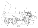
Figure 1 is a side elevation of an articulated load carrying vehicle; and -
Figure 2 is a perspective view of a drive train of the load carrying vehicle ofFigure 1 . - The method of the present disclosure may be used in any vehicle, in particular a load carrying vehicle, which has a payload carrier and a plurality of axles. Such vehicles include articulated or non-articulated vehicles. One
exemplary vehicle 10 is illustrated inFigure 1 in the form of an articulated tipper truck. Thevehicle 10 may comprise afirst frame 11, in this example a tractor unit, attached to asecond frame 12, in this example a trailer unit. Theframes coupling 13. Thefirst frame 11 may comprise anoperator cab 14 which houses the operator controls for thevehicle 10. The controls may include one or more brake actuators (such as pedals), a transmission gear select lever, one or more levers (such as a hoist lever for operating the vehicle's working equipment) and a steering device. The transmission gear select lever and hoist lever(s) may be combined into a single select lever. - The
coupling 13, which may be an articulation joint, may allow each of the first andsecond frames other frame vehicle 10 may be steered by adjusting the yaw angle of the first andsecond frames articulation 15 utilising actuators, for example hydraulic cylinders, suitably attached to each of the first andsecond frames coupling 13. Thecoupling 13 may allow the first andsecond frames roll axis 16 relative to one another. - The
second frame 12 may comprise apayload carrier 17, such as a dump body adapted to carry a load which is pivotally attached to achassis 18 of thefirst frame 11 at a pivot point. Thesecond frame 12 may comprise a material discharge mechanism in the form of a tipping system which, when activated, causes thepayload carrier 17 to rotate about the pivot from a "body down"position 19 into a "body up"tipping position 20. The tipping system may be any suitable system, such as, for example, a hydraulic, electric or mechanical system. As the tipping system rotates thepayload carrier 17 to the body up tippingposition 20, thepayload carrier 17 ejects any materials or load from thepayload carrier 17. Thepayload carrier 17 may be any type of container and may be open at the top, fully enclosed or partially enclosed. - In order for the load or materials to be ejected from the
payload carrier 17, instead of having a movable payload carrier which moves relative to thechassis 18, the vehicle may have a material discharge mechanism in the form of an ejector mechanism. Ejector mechanisms are well known in the art, and typically comprise an ejector plate which slides horizontally from one end of the inside of thepayload carrier 17 towards the other end (the ejection end) to push any load or materials out of thepayload carrier 17. A hydraulic actuator or the like may be used to move the ejector plate towards the ejection end of thepayload carrier 17. - The material discharge mechanism may be activated by an operator controlled material discharge mechanism selection lever located in the
operator cab 14. Operation of the lever may provide a material discharge request to the control system. - The vehicle may further comprise a
power unit 25, which may be an internal combustion engine, a micro-turbine, an electric motor or any other suitable unit, which provides a power output which may be used to drive thevehicle 10 and operate the material discharge mechanism and other of the venicle's systems. - The
vehicle 10 may comprise one or more terrain engaging means 21,22 in contact with theterrain 23. Theterrain 23 may be the ground or any surface on which theload carrying vehicle 10 is operated. The terrain engaging means 21,22 may be, for example, tracks and/or wheels which enable thevehicle 10 to move along theterrain 23 and thevehicle 10 may comprise any number ofterrain engaging means 22. As illustrated, thefirst frame 11 may have one pair of first frameground engaging means 22 and thesecond frame 12 may have two pairs second frameground engaging means 21, with one of each pair ofground engaging means vehicle 10. - The
vehicle 10 may further comprise a drive train, which may include atransmission 24 which is operated by the transmission gear select lever and enables to the operator to select an appropriate gear or transmission mode for the operation of thevehicle 10. The transmission modes may include a neutral mode, in which the gear trains within thetransmission 24 are disconnected, and one or more drive modes, such as forward (which allows the gear ratio to change automatically), reverse or one or more specific gears. - The drive train may couple the
power unit 25 to drive at least one of theterrain engaging means vehicle 10 along theterrain 23. The drive train may comprise a plurality ofaxles terrain engaging means first frame axle 27 may connect the pair of first frameground engaging means 22 and asecond frame axle 26 connects each member of the pairs of second frameground engaging means 22. Theaxles power unit 25 as described below. In the illustrated embodiment, thepower unit 25 may be mounted on thefirst frame 11 and the drive train may further comprise atorque transfer arrangement 30 for transferring torque from thepower unit 25 to the first frame terrain engaging means. - The
transmission 24 may be coupled to receive torque from thepower unit 25. Thetransmission 24 may have anoutput drive coupling 28 for providing the torque. Thetorque transfer arrangement 30 may include gearing 31, which may comprise a plurality of gears, a plurality of drive shafts, which may include a firstframe drive shaft 33 and a secondframe drive shaft 32, and an inter-axle differential which is an integral part of thegearing 31. Thedrive shafts gears 31 and may be adapted to receive a percentage of the torque and transmit the torque to the first andsecond frame axles coupling 28 to receive torque and provide the torque to more than one of the plurality ofgears 31. An inter-axle differential splits the input shaft torque between the first andsecond frame axles - The inter-axle differential may be provided with an inter-axle differential lock. The inter-axle differential lock may lock the first frame and
second frame axles ground engaging means - The
vehicle 10 may also be provided with one ormore brake mechanisms 29. The brake mechanism(s) 29 may include parking brakes, which are intended for use when thepower unit 25 is not running and thevehicle 10 is not being operated. In such situations thevehicle 10 may be brought to a halt on level ground, the parking brakes engaged and thepower unit 25 switched off. The brake mechanism(s) 29 may also include service brakes for situations in which theload carrying vehicle 10 may be stopped temporarily with thepower unit 25 still running, such as during loading and dumping. The service brakes may be activated by the operator via a foot pedal. - The brake mechanism(s) 29 may also have an automatic mode, in which one or both are engaged or disengaged by the control system.
- The
vehicle 10 may comprise a control system, which may comprise one or more electronic control units (ECUs) which have the ability to monitor operating parameters and to control operation of thepower unit 25, the brake mechanism(s) 29, the inter-axle differential lock and other elements of thevehicle 10. The control system may use software to provide control logic for the automatic engagement of the inter-axle differential lock and one or more of thebrake mechanisms 29 when certain conditions are met. These conditions may include that thevehicle 10 is substantially stationery, for example moving at a speed of less than lmph, that the transmission is in neutral and a material discharge request has been given. The control system may also increase the speed of thepower unit 25. - The control system may also automatically disengage the inter-axle differential lock and the brake mechanism(s) 29 when the transmission is placed in a drive mode.
- The control system is suitable for use with a variety of
vehicles 10 and in particular load carrying vehicles including a material discharge mechanism. However, the control system is particularly suited to articulated vehicles. - When the operator wishes to unload the
vehicle 10, he may bring the vehicle to a halt, which may be by means of the vehicle's service brakes. When the vehicle is stationary, the operator may select neutral transmission mode, for example by means of the transmission gear select lever. The operator may then activate the material discharge mechanism selection lever to request operation the material discharge system. When the control system determines that a material discharge request has been given, if it also determines that thevehicle 10 is substantially stationery and that the transmission is in neutral mode, it may automatically engage the inter-axle differential lock and one or more of thebrake mechanisms 29 and actuate the material discharge function. It may also increase the speed of thepower unit 25. - If, following determination of the material discharge demand, the control system does not determine that the
vehicle 10 is substantially stationery or that the transmission is in neutral mode, it may automatically engage the inter-axle differential lock but not engage one or more of thebrake mechanisms 29. Instead it will only activate the material discharge system. This enables the operator to discharge the material in an even layer by tipping/ejecting whilst diving forward. - When the material discharge function is completed, the operator may select a drive mode (forward or reverse), for example by means of the transmission gear select lever before moving off. On determination that the transmission is no longer in neutral mode, the control system automatically disengages the inter-axle differential lock and the brake mechanism(s) 29 to allow the
vehicle 10 to move off. - The control system may therefore enable the automatic synchronisation of the operation of the inter-axle differential lock and the brake mechanism(s) 29 with operation of the material discharge mechanism to enable the operator to focus on driving the
vehicle 10. This may optimise material discharge time and thereby improve productivity. The control system may also improve vehicle stability by ensuring that the drive train is locked during static unloading events. By applying the inter-axle differential lock and brake mechanism(s), the driveline is locked up. This may have the effect of preventing relative rotation through thecoupling 13. If thefirst frame 11 is prevented from rotating relative to thesecond frame 12, if thefirst frame 11 rises off the ground, it stays in the same orientation as thesecond frame 12 and may not roll onto the ground.
Claims (11)
- A vehicle comprising:a material discharge mechanism;a plurality of axles;an inter-axle differential connecting the plurality of axles;a transmission having at least one drive mode and a neutral mode;at least one brake mechanism; anda control system, said control system being configured to engage the at least one brake mechanism and lock the inter-axle differential when it determines that activation of the material discharge mechanism has been requested and the transmission is in neutral mode.
- A vehicle as claimed in claim 1, wherein the control system engages the at least one brake mechanism and locks the inter-axle differential if it determines that the vehicle is substantially stationery.
- A vehicle as claimed in claim 1 or claim 2, wherein the vehicle further comprises a power unit providing a power output for operating the material discharge mechanism, and the control system increases the power output of the power unit when it determines that activation of the material discharge mechanism has been requested and the transmission is in neutral mode.
- A vehicle as claimed in any one of the preceding claims, wherein the control system is configured to disengage the at least one brake mechanism and unlock the inter-axle differential when it determines that the transmission is in a drive mode.
- A vehicle as claimed in any one of the preceding claims further comprising an operator controlled material discharge mechanism selection lever, the operation of which requests activation of the material discharge mechanism.
- A vehicle as claimed in any one of the preceding claims further comprising a hydraulically operated inter-axle differential lock.
- A vehicle as claimed in any one of the preceding claims in which the at least one brake mechanism comprises at least one service brake.
- A method of controlling a vehicle, said vehicle comprising:a material discharge mechanism;a plurality of axles;an inter-axle differential connecting the plurality of axles;a transmission having at least one drive mode and a neutral mode; andat least one brake mechanism,said method comprising the steps of:placing the transmission in neutral mode; andrequesting activation of the material discharge mechanism,wherein the at least one brake mechanism is automatically engaged and the inter-axle differential is automatically locked.
- A method of controlling a vehicle as claimed in claim 8 further comprising the step of bringing the vehicle to a halt before the at least one brake mechanism is automatically engaged and the inter-axle differential is automatically locked.
- A method of controlling a vehicle as claimed in claim 8 or claim 9 in which the vehicle further comprises power unit providing a power output for operating the material discharge mechanism, and the power output of the power unit is increased after the steps of placing the transmission in neutral mode and requesting activation of the material discharge mechanism.
- A method of controlling a vehicle as claimed in any one of claims 8 to 10 in which the at least one brake mechanism is automatically disengaged and the inter-axle differential is automatically unlocked when the transmission is moved from neutral mode to a drive mode.
Priority Applications (4)
| Application Number | Priority Date | Filing Date | Title |
|---|---|---|---|
| EP14170504.6A EP2949507A1 (en) | 2014-05-29 | 2014-05-29 | Vehicle and method of controlling a vehicle |
| CN201580025595.9A CN106458077A (en) | 2014-05-29 | 2015-04-07 | Vehicle and method of controlling a vehicle |
| US15/310,373 US20170136932A1 (en) | 2014-05-29 | 2015-04-07 | Vehicle and Method of Controlling a Vehicle |
| PCT/EP2015/057520 WO2015180880A1 (en) | 2014-05-29 | 2015-04-07 | Vehicle and method of controlling a vehicle |
Applications Claiming Priority (1)
| Application Number | Priority Date | Filing Date | Title |
|---|---|---|---|
| EP14170504.6A EP2949507A1 (en) | 2014-05-29 | 2014-05-29 | Vehicle and method of controlling a vehicle |
Publications (1)
| Publication Number | Publication Date |
|---|---|
| EP2949507A1 true EP2949507A1 (en) | 2015-12-02 |
Family
ID=50841636
Family Applications (1)
| Application Number | Title | Priority Date | Filing Date |
|---|---|---|---|
| EP14170504.6A Withdrawn EP2949507A1 (en) | 2014-05-29 | 2014-05-29 | Vehicle and method of controlling a vehicle |
Country Status (4)
| Country | Link |
|---|---|
| US (1) | US20170136932A1 (en) |
| EP (1) | EP2949507A1 (en) |
| CN (1) | CN106458077A (en) |
| WO (1) | WO2015180880A1 (en) |
Cited By (5)
| Publication number | Priority date | Publication date | Assignee | Title |
|---|---|---|---|---|
| WO2018189202A1 (en) * | 2017-04-11 | 2018-10-18 | Dana Italia S.R.L. | A hydraulic circuit for an adaptive park braking system and method of operation thereof |
| DE102017220537A1 (en) | 2017-11-17 | 2019-05-23 | Zf Friedrichshafen Ag | Longitudinal locking device for working machine |
| DE102017221978A1 (en) * | 2017-12-06 | 2019-06-06 | Zf Friedrichshafen Ag | Differential locking device for working machine |
| CN111381251A (en) * | 2020-03-18 | 2020-07-07 | 杭州微萤科技有限公司 | Positioning system and synchronization chain self-optimization method thereof |
| DE102019204129A1 (en) * | 2019-03-26 | 2020-10-01 | Zf Friedrichshafen Ag | Method for controlling a driving dynamics function of a work machine |
Families Citing this family (3)
| Publication number | Priority date | Publication date | Assignee | Title |
|---|---|---|---|---|
| EP3625111B1 (en) | 2017-05-15 | 2021-12-01 | Volvo Construction Equipment AB | A method and control unit for preventing a rollover situation of an articulated vehicle |
| JP2019194042A (en) * | 2018-05-01 | 2019-11-07 | ヤマハ発動機株式会社 | vehicle |
| CN113415158B (en) * | 2021-07-30 | 2022-09-09 | 东风商用车有限公司 | Control method and control system for tractor drive axle |
Citations (3)
| Publication number | Priority date | Publication date | Assignee | Title |
|---|---|---|---|---|
| US3606059A (en) * | 1969-12-15 | 1971-09-20 | Herbert Haberle Jr | Roll-off trailer |
| US4076326A (en) * | 1976-12-22 | 1978-02-28 | Angelo Joe B D | Automatic safety brake system |
| US20100252349A1 (en) * | 2009-04-02 | 2010-10-07 | Marshall Excelsior Company | Nozzle actuated system for disabling a vehicle |
Family Cites Families (6)
| Publication number | Priority date | Publication date | Assignee | Title |
|---|---|---|---|---|
| SE515446C2 (en) * | 2000-06-05 | 2001-08-06 | Volvo Articulated Haulers Ab | Device and method for controlling specific functions of a loading vehicle when tipping and / or loading the vehicle's surface |
| JP2002087095A (en) * | 2000-09-12 | 2002-03-26 | Komatsu Ltd | Tire lock prevention device for vehicle |
| US8082088B2 (en) * | 2005-09-20 | 2011-12-20 | Volvo Construction Equipment Ab | Method for controlling rotation speed |
| US7980983B2 (en) * | 2008-02-25 | 2011-07-19 | Chrysler Group Llc | Hydraulically locking limited slip differential |
| US20110072811A1 (en) * | 2009-09-30 | 2011-03-31 | Rs Drawings, Llc | Engine driven lift gate power system |
| US8312956B2 (en) * | 2011-02-15 | 2012-11-20 | Deere & Company | Auto inter-axle differential lock engagement for improved braking capacity |
-
2014
- 2014-05-29 EP EP14170504.6A patent/EP2949507A1/en not_active Withdrawn
-
2015
- 2015-04-07 US US15/310,373 patent/US20170136932A1/en not_active Abandoned
- 2015-04-07 CN CN201580025595.9A patent/CN106458077A/en active Pending
- 2015-04-07 WO PCT/EP2015/057520 patent/WO2015180880A1/en active Application Filing
Patent Citations (3)
| Publication number | Priority date | Publication date | Assignee | Title |
|---|---|---|---|---|
| US3606059A (en) * | 1969-12-15 | 1971-09-20 | Herbert Haberle Jr | Roll-off trailer |
| US4076326A (en) * | 1976-12-22 | 1978-02-28 | Angelo Joe B D | Automatic safety brake system |
| US20100252349A1 (en) * | 2009-04-02 | 2010-10-07 | Marshall Excelsior Company | Nozzle actuated system for disabling a vehicle |
Cited By (11)
| Publication number | Priority date | Publication date | Assignee | Title |
|---|---|---|---|---|
| WO2018189202A1 (en) * | 2017-04-11 | 2018-10-18 | Dana Italia S.R.L. | A hydraulic circuit for an adaptive park braking system and method of operation thereof |
| CN110709294A (en) * | 2017-04-11 | 2020-01-17 | 意大利德纳有限责任公司 | Hydraulic circuit for adaptive parking brake system and method of operating the same |
| CN110709294B (en) * | 2017-04-11 | 2022-06-17 | 意大利德纳有限责任公司 | Hydraulic circuit for adaptive parking brake system and method of operating the same |
| US11649608B2 (en) | 2017-04-11 | 2023-05-16 | Dana Italia S.R.L. | Hydraulic circuit for an adaptive park braking system and method of operation thereof |
| DE102017220537A1 (en) | 2017-11-17 | 2019-05-23 | Zf Friedrichshafen Ag | Longitudinal locking device for working machine |
| DE102017220537B4 (en) | 2017-11-17 | 2019-06-06 | Zf Friedrichshafen Ag | Longitudinal locking device for working machine |
| DE102017221978A1 (en) * | 2017-12-06 | 2019-06-06 | Zf Friedrichshafen Ag | Differential locking device for working machine |
| DE102017221978B4 (en) * | 2017-12-06 | 2020-11-12 | Zf Friedrichshafen Ag | Differential lock device for work machine |
| DE102019204129A1 (en) * | 2019-03-26 | 2020-10-01 | Zf Friedrichshafen Ag | Method for controlling a driving dynamics function of a work machine |
| WO2020193308A1 (en) | 2019-03-26 | 2020-10-01 | Zf Friedrichshafen Ag | Method for controlling a driving dynamics function of a working machine |
| CN111381251A (en) * | 2020-03-18 | 2020-07-07 | 杭州微萤科技有限公司 | Positioning system and synchronization chain self-optimization method thereof |
Also Published As
| Publication number | Publication date |
|---|---|
| WO2015180880A1 (en) | 2015-12-03 |
| US20170136932A1 (en) | 2017-05-18 |
| CN106458077A (en) | 2017-02-22 |
Similar Documents
| Publication | Publication Date | Title |
|---|---|---|
| EP2949507A1 (en) | Vehicle and method of controlling a vehicle | |
| US5332052A (en) | Detachable all terrain trailer | |
| CN104395169B (en) | Control strategy for AWD connections and disconnection | |
| EP2244920B2 (en) | A method and system for braking a vehicle | |
| US8640811B2 (en) | Frame-steered vehicle and a method for controlling a frame-steered vehicle | |
| US9821780B2 (en) | Automated differential lock | |
| TWI706875B (en) | Truck with lowerable bed | |
| CN101224861B (en) | Static hydraulic driven big-tonnage hinged -frame all-terrain container fork lift | |
| EP2139714B1 (en) | A power transmission arrangement | |
| US9845039B2 (en) | System and method of automatically operating a hoist system for a machine | |
| CN115289192A (en) | Transmission device | |
| CA2835887A1 (en) | Method and system for controlling a differential configuration | |
| US20210380084A1 (en) | Method and control system for controlling machine | |
| WO2016085369A1 (en) | A method and control unit for preventing rollover of a tractor unit of a working machine | |
| US3225852A (en) | Traction for earth movers and the like | |
| US9625036B2 (en) | Braking system | |
| JP4796432B2 (en) | Work vehicle travel stop control device | |
| CN115867736A (en) | Hub for mounting a wheel on an axle of a work vehicle | |
| JP3268568B2 (en) | Steering control device for traveling vehicles | |
| JP3886361B2 (en) | Rotary snowplow | |
| JPH07215236A (en) | Carrier | |
| JP3833102B2 (en) | Rotary snowplow | |
| NL8203168A (en) | TOWING VEHICLE FOR AIR fields. | |
| WO2018171894A1 (en) | A transmission assembly | |
| US20150323069A1 (en) | Braking System |
Legal Events
| Date | Code | Title | Description |
|---|---|---|---|
| AK | Designated contracting states |
Kind code of ref document: A1 Designated state(s): AL AT BE BG CH CY CZ DE DK EE ES FI FR GB GR HR HU IE IS IT LI LT LU LV MC MK MT NL NO PL PT RO RS SE SI SK SM TR |
|
| AX | Request for extension of the european patent |
Extension state: BA ME |
|
| PUAI | Public reference made under article 153(3) epc to a published international application that has entered the european phase |
Free format text: ORIGINAL CODE: 0009012 |
|
| 17P | Request for examination filed |
Effective date: 20160601 |
|
| RBV | Designated contracting states (corrected) |
Designated state(s): AL AT BE BG CH CY CZ DE DK EE ES FI FR GB GR HR HU IE IS IT LI LT LU LV MC MK MT NL NO PL PT RO RS SE SI SK SM TR |
|
| GRAP | Despatch of communication of intention to grant a patent |
Free format text: ORIGINAL CODE: EPIDOSNIGR1 |
|
| INTG | Intention to grant announced |
Effective date: 20161111 |
|
| GRAS | Grant fee paid |
Free format text: ORIGINAL CODE: EPIDOSNIGR3 |
|
| STAA | Information on the status of an ep patent application or granted ep patent |
Free format text: STATUS: THE APPLICATION IS DEEMED TO BE WITHDRAWN |
|
| 18D | Application deemed to be withdrawn |
Effective date: 20171201 |