EP2949294A2 - Prosthesis or orthesis with removable wall piece - Google Patents
Prosthesis or orthesis with removable wall piece Download PDFInfo
- Publication number
- EP2949294A2 EP2949294A2 EP15168896.7A EP15168896A EP2949294A2 EP 2949294 A2 EP2949294 A2 EP 2949294A2 EP 15168896 A EP15168896 A EP 15168896A EP 2949294 A2 EP2949294 A2 EP 2949294A2
- Authority
- EP
- European Patent Office
- Prior art keywords
- wall piece
- prosthesis
- wall
- body part
- integrated
- Prior art date
- Legal status (The legal status is an assumption and is not a legal conclusion. Google has not performed a legal analysis and makes no representation as to the accuracy of the status listed.)
- Granted
Links
Images


Classifications
-
- A—HUMAN NECESSITIES
- A61—MEDICAL OR VETERINARY SCIENCE; HYGIENE
- A61N—ELECTROTHERAPY; MAGNETOTHERAPY; RADIATION THERAPY; ULTRASOUND THERAPY
- A61N2/00—Magnetotherapy
- A61N2/06—Magnetotherapy using magnetic fields produced by permanent magnets
-
- A—HUMAN NECESSITIES
- A61—MEDICAL OR VETERINARY SCIENCE; HYGIENE
- A61F—FILTERS IMPLANTABLE INTO BLOOD VESSELS; PROSTHESES; DEVICES PROVIDING PATENCY TO, OR PREVENTING COLLAPSING OF, TUBULAR STRUCTURES OF THE BODY, e.g. STENTS; ORTHOPAEDIC, NURSING OR CONTRACEPTIVE DEVICES; FOMENTATION; TREATMENT OR PROTECTION OF EYES OR EARS; BANDAGES, DRESSINGS OR ABSORBENT PADS; FIRST-AID KITS
- A61F2/00—Filters implantable into blood vessels; Prostheses, i.e. artificial substitutes or replacements for parts of the body; Appliances for connecting them with the body; Devices providing patency to, or preventing collapsing of, tubular structures of the body, e.g. stents
- A61F2/50—Prostheses not implantable in the body
- A61F2/78—Means for protecting prostheses or for attaching them to the body, e.g. bandages, harnesses, straps, or stockings for the limb stump
- A61F2/80—Sockets, e.g. of suction type
-
- A—HUMAN NECESSITIES
- A61—MEDICAL OR VETERINARY SCIENCE; HYGIENE
- A61H—PHYSICAL THERAPY APPARATUS, e.g. DEVICES FOR LOCATING OR STIMULATING REFLEX POINTS IN THE BODY; ARTIFICIAL RESPIRATION; MASSAGE; BATHING DEVICES FOR SPECIAL THERAPEUTIC OR HYGIENIC PURPOSES OR SPECIFIC PARTS OF THE BODY
- A61H39/00—Devices for locating or stimulating specific reflex points of the body for physical therapy, e.g. acupuncture
- A61H39/002—Using electric currents
-
- A—HUMAN NECESSITIES
- A61—MEDICAL OR VETERINARY SCIENCE; HYGIENE
- A61H—PHYSICAL THERAPY APPARATUS, e.g. DEVICES FOR LOCATING OR STIMULATING REFLEX POINTS IN THE BODY; ARTIFICIAL RESPIRATION; MASSAGE; BATHING DEVICES FOR SPECIAL THERAPEUTIC OR HYGIENIC PURPOSES OR SPECIFIC PARTS OF THE BODY
- A61H39/00—Devices for locating or stimulating specific reflex points of the body for physical therapy, e.g. acupuncture
- A61H39/04—Devices for pressing such points, e.g. Shiatsu or Acupressure
-
- A—HUMAN NECESSITIES
- A61—MEDICAL OR VETERINARY SCIENCE; HYGIENE
- A61B—DIAGNOSIS; SURGERY; IDENTIFICATION
- A61B2560/00—Constructional details of operational features of apparatus; Accessories for medical measuring apparatus
- A61B2560/02—Operational features
- A61B2560/0242—Operational features adapted to measure environmental factors, e.g. temperature, pollution
-
- A—HUMAN NECESSITIES
- A61—MEDICAL OR VETERINARY SCIENCE; HYGIENE
- A61B—DIAGNOSIS; SURGERY; IDENTIFICATION
- A61B2562/00—Details of sensors; Constructional details of sensor housings or probes; Accessories for sensors
- A61B2562/02—Details of sensors specially adapted for in-vivo measurements
- A61B2562/0271—Thermal or temperature sensors
-
- A—HUMAN NECESSITIES
- A61—MEDICAL OR VETERINARY SCIENCE; HYGIENE
- A61B—DIAGNOSIS; SURGERY; IDENTIFICATION
- A61B5/00—Measuring for diagnostic purposes; Identification of persons
- A61B5/01—Measuring temperature of body parts ; Diagnostic temperature sensing, e.g. for malignant or inflamed tissue
-
- A—HUMAN NECESSITIES
- A61—MEDICAL OR VETERINARY SCIENCE; HYGIENE
- A61B—DIAGNOSIS; SURGERY; IDENTIFICATION
- A61B5/00—Measuring for diagnostic purposes; Identification of persons
- A61B5/02—Detecting, measuring or recording pulse, heart rate, blood pressure or blood flow; Combined pulse/heart-rate/blood pressure determination; Evaluating a cardiovascular condition not otherwise provided for, e.g. using combinations of techniques provided for in this group with electrocardiography or electroauscultation; Heart catheters for measuring blood pressure
- A61B5/021—Measuring pressure in heart or blood vessels
-
- A—HUMAN NECESSITIES
- A61—MEDICAL OR VETERINARY SCIENCE; HYGIENE
- A61F—FILTERS IMPLANTABLE INTO BLOOD VESSELS; PROSTHESES; DEVICES PROVIDING PATENCY TO, OR PREVENTING COLLAPSING OF, TUBULAR STRUCTURES OF THE BODY, e.g. STENTS; ORTHOPAEDIC, NURSING OR CONTRACEPTIVE DEVICES; FOMENTATION; TREATMENT OR PROTECTION OF EYES OR EARS; BANDAGES, DRESSINGS OR ABSORBENT PADS; FIRST-AID KITS
- A61F7/00—Heating or cooling appliances for medical or therapeutic treatment of the human body
- A61F2007/0001—Body part
- A61F2007/0051—Stumps after amputation
-
- A—HUMAN NECESSITIES
- A61—MEDICAL OR VETERINARY SCIENCE; HYGIENE
- A61H—PHYSICAL THERAPY APPARATUS, e.g. DEVICES FOR LOCATING OR STIMULATING REFLEX POINTS IN THE BODY; ARTIFICIAL RESPIRATION; MASSAGE; BATHING DEVICES FOR SPECIAL THERAPEUTIC OR HYGIENIC PURPOSES OR SPECIFIC PARTS OF THE BODY
- A61H2201/00—Characteristics of apparatus not provided for in the preceding codes
- A61H2201/02—Characteristics of apparatus not provided for in the preceding codes heated or cooled
- A61H2201/0207—Characteristics of apparatus not provided for in the preceding codes heated or cooled heated
-
- A—HUMAN NECESSITIES
- A61—MEDICAL OR VETERINARY SCIENCE; HYGIENE
- A61H—PHYSICAL THERAPY APPARATUS, e.g. DEVICES FOR LOCATING OR STIMULATING REFLEX POINTS IN THE BODY; ARTIFICIAL RESPIRATION; MASSAGE; BATHING DEVICES FOR SPECIAL THERAPEUTIC OR HYGIENIC PURPOSES OR SPECIFIC PARTS OF THE BODY
- A61H2201/00—Characteristics of apparatus not provided for in the preceding codes
- A61H2201/02—Characteristics of apparatus not provided for in the preceding codes heated or cooled
- A61H2201/0214—Characteristics of apparatus not provided for in the preceding codes heated or cooled cooled
-
- A—HUMAN NECESSITIES
- A61—MEDICAL OR VETERINARY SCIENCE; HYGIENE
- A61H—PHYSICAL THERAPY APPARATUS, e.g. DEVICES FOR LOCATING OR STIMULATING REFLEX POINTS IN THE BODY; ARTIFICIAL RESPIRATION; MASSAGE; BATHING DEVICES FOR SPECIAL THERAPEUTIC OR HYGIENIC PURPOSES OR SPECIFIC PARTS OF THE BODY
- A61H2201/00—Characteristics of apparatus not provided for in the preceding codes
- A61H2201/16—Physical interface with patient
- A61H2201/1602—Physical interface with patient kind of interface, e.g. head rest, knee support or lumbar support
- A61H2201/1619—Thorax
-
- A—HUMAN NECESSITIES
- A61—MEDICAL OR VETERINARY SCIENCE; HYGIENE
- A61H—PHYSICAL THERAPY APPARATUS, e.g. DEVICES FOR LOCATING OR STIMULATING REFLEX POINTS IN THE BODY; ARTIFICIAL RESPIRATION; MASSAGE; BATHING DEVICES FOR SPECIAL THERAPEUTIC OR HYGIENIC PURPOSES OR SPECIFIC PARTS OF THE BODY
- A61H2201/00—Characteristics of apparatus not provided for in the preceding codes
- A61H2201/16—Physical interface with patient
- A61H2201/1602—Physical interface with patient kind of interface, e.g. head rest, knee support or lumbar support
- A61H2201/1635—Hand or arm, e.g. handle
-
- A—HUMAN NECESSITIES
- A61—MEDICAL OR VETERINARY SCIENCE; HYGIENE
- A61H—PHYSICAL THERAPY APPARATUS, e.g. DEVICES FOR LOCATING OR STIMULATING REFLEX POINTS IN THE BODY; ARTIFICIAL RESPIRATION; MASSAGE; BATHING DEVICES FOR SPECIAL THERAPEUTIC OR HYGIENIC PURPOSES OR SPECIFIC PARTS OF THE BODY
- A61H2201/00—Characteristics of apparatus not provided for in the preceding codes
- A61H2201/16—Physical interface with patient
- A61H2201/1602—Physical interface with patient kind of interface, e.g. head rest, knee support or lumbar support
- A61H2201/164—Feet or leg, e.g. pedal
-
- A—HUMAN NECESSITIES
- A61—MEDICAL OR VETERINARY SCIENCE; HYGIENE
- A61H—PHYSICAL THERAPY APPARATUS, e.g. DEVICES FOR LOCATING OR STIMULATING REFLEX POINTS IN THE BODY; ARTIFICIAL RESPIRATION; MASSAGE; BATHING DEVICES FOR SPECIAL THERAPEUTIC OR HYGIENIC PURPOSES OR SPECIFIC PARTS OF THE BODY
- A61H2201/00—Characteristics of apparatus not provided for in the preceding codes
- A61H2201/16—Physical interface with patient
- A61H2201/1602—Physical interface with patient kind of interface, e.g. head rest, knee support or lumbar support
- A61H2201/165—Wearable interfaces
-
- A—HUMAN NECESSITIES
- A61—MEDICAL OR VETERINARY SCIENCE; HYGIENE
- A61H—PHYSICAL THERAPY APPARATUS, e.g. DEVICES FOR LOCATING OR STIMULATING REFLEX POINTS IN THE BODY; ARTIFICIAL RESPIRATION; MASSAGE; BATHING DEVICES FOR SPECIAL THERAPEUTIC OR HYGIENIC PURPOSES OR SPECIFIC PARTS OF THE BODY
- A61H2201/00—Characteristics of apparatus not provided for in the preceding codes
- A61H2201/16—Physical interface with patient
- A61H2201/1683—Surface of interface
- A61H2201/169—Physical characteristics of the surface, e.g. material, relief, texture or indicia
- A61H2201/1695—Enhanced pressure effect, e.g. substantially sharp projections, needles or pyramids
-
- A—HUMAN NECESSITIES
- A61—MEDICAL OR VETERINARY SCIENCE; HYGIENE
- A61H—PHYSICAL THERAPY APPARATUS, e.g. DEVICES FOR LOCATING OR STIMULATING REFLEX POINTS IN THE BODY; ARTIFICIAL RESPIRATION; MASSAGE; BATHING DEVICES FOR SPECIAL THERAPEUTIC OR HYGIENIC PURPOSES OR SPECIFIC PARTS OF THE BODY
- A61H2230/00—Measuring physical parameters of the user
- A61H2230/25—Blood flowrate, e.g. by Doppler effect
-
- A—HUMAN NECESSITIES
- A61—MEDICAL OR VETERINARY SCIENCE; HYGIENE
- A61H—PHYSICAL THERAPY APPARATUS, e.g. DEVICES FOR LOCATING OR STIMULATING REFLEX POINTS IN THE BODY; ARTIFICIAL RESPIRATION; MASSAGE; BATHING DEVICES FOR SPECIAL THERAPEUTIC OR HYGIENIC PURPOSES OR SPECIFIC PARTS OF THE BODY
- A61H2230/00—Measuring physical parameters of the user
- A61H2230/30—Blood pressure
-
- A—HUMAN NECESSITIES
- A61—MEDICAL OR VETERINARY SCIENCE; HYGIENE
- A61H—PHYSICAL THERAPY APPARATUS, e.g. DEVICES FOR LOCATING OR STIMULATING REFLEX POINTS IN THE BODY; ARTIFICIAL RESPIRATION; MASSAGE; BATHING DEVICES FOR SPECIAL THERAPEUTIC OR HYGIENIC PURPOSES OR SPECIFIC PARTS OF THE BODY
- A61H2230/00—Measuring physical parameters of the user
- A61H2230/50—Temperature
-
- A—HUMAN NECESSITIES
- A61—MEDICAL OR VETERINARY SCIENCE; HYGIENE
- A61H—PHYSICAL THERAPY APPARATUS, e.g. DEVICES FOR LOCATING OR STIMULATING REFLEX POINTS IN THE BODY; ARTIFICIAL RESPIRATION; MASSAGE; BATHING DEVICES FOR SPECIAL THERAPEUTIC OR HYGIENIC PURPOSES OR SPECIFIC PARTS OF THE BODY
- A61H23/00—Percussion or vibration massage, e.g. using supersonic vibration; Suction-vibration massage; Massage with moving diaphragms
- A61H23/02—Percussion or vibration massage, e.g. using supersonic vibration; Suction-vibration massage; Massage with moving diaphragms with electric or magnetic drive
-
- A—HUMAN NECESSITIES
- A61—MEDICAL OR VETERINARY SCIENCE; HYGIENE
- A61M—DEVICES FOR INTRODUCING MEDIA INTO, OR ONTO, THE BODY; DEVICES FOR TRANSDUCING BODY MEDIA OR FOR TAKING MEDIA FROM THE BODY; DEVICES FOR PRODUCING OR ENDING SLEEP OR STUPOR
- A61M35/00—Devices for applying media, e.g. remedies, on the human body
-
- A—HUMAN NECESSITIES
- A61—MEDICAL OR VETERINARY SCIENCE; HYGIENE
- A61N—ELECTROTHERAPY; MAGNETOTHERAPY; RADIATION THERAPY; ULTRASOUND THERAPY
- A61N1/00—Electrotherapy; Circuits therefor
- A61N1/02—Details
- A61N1/04—Electrodes
- A61N1/0404—Electrodes for external use
- A61N1/0408—Use-related aspects
- A61N1/0456—Specially adapted for transcutaneous electrical nerve stimulation [TENS]
-
- A—HUMAN NECESSITIES
- A61—MEDICAL OR VETERINARY SCIENCE; HYGIENE
- A61N—ELECTROTHERAPY; MAGNETOTHERAPY; RADIATION THERAPY; ULTRASOUND THERAPY
- A61N7/00—Ultrasound therapy
Definitions
- the invention relates to a prosthesis or orthosis for the replacement of external body parts or limbs, for example, after amputations, or for stabilizing, relieving, immobilizing and guiding limbs or trunk or for correcting malpositions of limbs or trunk.
- the prostheses or orthoses known in the prior art, it is usually possible to treat an amputation stump or a limb treated with an orthosis only after removal of the prosthesis or orthosis, eg for administration of a medicament into the body tissue. If the prosthesis or orthosis is applied to the amputation stump or the body part to be treated, the prosthesis socket or the shell parts of the orthosis cover the amputation stump or the body part over a large area, so that the stump or the body part can not subsequently be supplied with drugs locally.
- prostheses or orthoses which have over the above functions, such as the replacement or immobilization of limbs, other functions.
- prostheses or orthoses which have arranged in the prosthesis stem heating elements for heating an amputation stump or pressure elements for the stimulation of acupressure points.
- Other prostheses or orthoses include sensors for monitoring body conditions, such as blood pressure or body temperature.
- prostheses or orthoses either have only one of these additional functionalities or have to be individually equipped with the desired functionalities for each patient.
- a subsequent change in the functionality of the prosthesis or orthosis, especially while this is applied to a body part, is no longer possible, since the corresponding devices are firmly installed in the prosthesis socket or the orthosis.
- the prosthesis or orthosis according to the invention has a shaft for receiving a body part.
- the shank has a wall bounding a body part receiving region, wherein a part of the wall is designed as a removable wall piece.
- the wall piece has an inner side facing the body part receiving area and an outer side facing away from the body part receiving area. Through the wall piece is a Through opening in the wall can be opened and closed, wherein the passage opening connects the body part receiving area with an outside area of the prosthesis or orthosis.
- the removable wall piece thus provides a locally selectable access to the received by a prosthesis amputation stump or received by an orthosis body part, so that the amputation stump or the body part can be treated without having to remove the prosthesis or orthosis.
- the wall piece is preferably arched in accordance with a part of the wall adjoining the wall piece, so that the wall piece fits into the wall of the shank in a smooth or dimensionally appropriate manner.
- the wall piece also fits visually into the wall, which improves the appearance of the shaft. Furthermore, this achieves a smooth shaft surface, which increases the wearing comfort, for example, under clothing.
- the wall piece may also be configured as flat, circular, square, rectangular, polygonal, round and / or oval, also independent of the curvature or curvature of a part of the wall adjoining the wall piece.
- the wall piece closes almost or completely positively with the part of the wall adjacent to the wall piece. This improves the appearance of the prosthesis or orthosis.
- the wall piece may further comprise a seal for airtight or almost airtight sealing of the through hole. In this way, after closing the passage opening with the wall piece, a vacuum can be maintained in the prosthesis socket.
- the seal can also serve to seal the passage opening against moisture and / or dirt. This is the penetration of dirt and moisture between wall piece and wall.
- the seal may be configured as a circumferential around the wall piece sealing ring.
- the outside of the wall piece can hook and a body part receiving portion facing away from the outside of a wall piece adjacent to the part of the wall Undercuts or eyes have, by which the wall piece can be clamped to the wall.
- the wall can have a through-opening circumferential thread into which the wall piece can be screwed and out of which the wall piece can be unscrewed.
- the wall piece may have a thickness which is smaller, greater than or equal to a thickness of a part of the wall adjoining the wall piece. Furthermore, the wall piece may have a width between 2 and 10 cm, preferably between 4 and 8 cm, preferably 6 cm, a length between 2 and 10 cm, preferably between 4 and 8 cm, preferably 6 cm, and / or a thickness between 0.5 and 5 cm, preferably between 1 and 3 cm, more preferably of 2 cm. In the case of a round wall piece, the wall piece may have a diameter between 2 and 10 cm, preferably between 4 and 8 cm, preferably 6 cm.
- the wall piece and the wall may have the same and / or different materials or consist thereof.
- the wall piece can be equipped with one or more special functionalities.
- a pressure pad for the acupressure of a specific acupressure point or a nerve tract of an amputation stump or a body part can be attached to the inside of the wall piece.
- Such a pressure pad can also serve to fix the prosthesis or orthosis to the body part.
- the pressure pad preferably contains or consists of air, foam, a pad, an elastic material, a soft Shore grade material, and / or a rigid material.
- a surface of the pressure pad may be smooth, rough and / or adhesive and / or have a relief and / or nubs. The nubs can be completely filled with material or hollow.
- a drug depot for dispensing a drug may be attached to an amputation stump or a body part or integrated into the wall piece.
- a drug depot for dispensing a drug may be attached to an amputation stump or a body part or integrated into the wall piece.
- several drug depots may be attached or integrated into the wall piece, if different drugs are to be administered simultaneously.
- a heating / cooling element for heating and / or cooling the body part and / or arterial blood at a central inflow point of the arterial blood may be attached or integrated into the wall piece on the inside of the wall piece.
- a moisture-absorbing material or an electronically and / or mechanically acting dehumidifying element for dehydration of a moist indoor climate can be mounted or integrated into the wall piece.
- the moisture absorbent material may be attached to the wall piece, for example in the form of pads.
- a measuring device for detecting bionic data such.
- a surface pressure at defined measuring points a shank interior temperature and / or a degree of moisture or integrated into the wall piece.
- a permanent magnet or an electromagnet for generating a magnetic field or integrated into the wall piece.
- Pulsed electromagnetic fields should have a bioenergetic positive influence on the organism at certain frequencies and promote blood circulation in order to stimulate cell metabolism.
- Another possibility provides to install on the inside of the wall piece, a piezoelectric element for electrical and / or mechanical stimulation of the body part or to integrate into the wall piece.
- a vibration element may be attached or integrated into the wall piece, wherein the vibration element is in mechanical contact with the body part.
- the vibrating element transmits mechanical vibrations to the body part received by the prosthesis or orthosis. This promotes the relaxation of the muscles and the blood circulation of the body part and reduces muscle tension.
- an electrode for removing myoelectric pulses from the body part for controlling mechanical joints of the prosthesis or orthosis may be attached or integrated into the wall piece.
- a temperature and / or movement logger can be mounted on the inside of the wall piece or integrated into the wall piece.
- a further advantageous embodiment of the invention provides that on the inside of the wall piece, a TENS electrode or a TENS device is mounted or integrated in the wall piece, wherein the TENS electrode or the TENS device is in electrically conductive contact with the body part ,
- a TENS device is used for pain treatment of limbs.
- the TENS devices deliver an electrical stimulation to the skin via electrodes.
- the therapeutic goal is to reduce pain by reducing or preventing pain transmission to the brain.
- Such a TENS device is used, for example, in the treatment of phantom pain.
- a sensor for a functional electrical stimulation of the body part e.g. for treatment after a stroke, attached or integrated into the wall piece.
- the wall is a variety of removable Wall pieces, wherein in each case a passage opening can be opened and closed by a wall piece, wherein the passage openings connect the body part receiving area with an outer region of the prosthesis or orthosis.
- a passage opening can be opened and closed by a wall piece, wherein the passage openings connect the body part receiving area with an outer region of the prosthesis or orthosis.
- several different locations of the body part received by the prosthesis or the orthosis can be made accessible from the outside.
- this allows different pieces of wall to equip with different functionalities.
- One or more or all wall pieces may also be arranged along acupuncture meridians and / or nerve tracts of the body part. By arranged on the wall pieces pressure pad or TENS electrodes these acupuncture meridians and / or nerve tracts can then be stimulated and pain in the body part to be treated.
- one or more or all of the wall pieces may be disposed along areas between muscles of the body part. If the wall pieces are then equipped, for example, with a pressure pad in each case, the prosthesis or orthosis can be supported against the muscle gaps, for example against twisting along the circumference of the body part or slippage in the longitudinal direction of the body part, thus improving the fit of the prosthesis or orthosis.
- the prosthesis stem is preferably cylindrical or conical in shape and may be designed as single-shell or multi-shell.
- the prosthesis or orthosis described herein may be, for example, an Arman prosthetic leg or brace or torso corset.
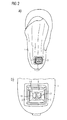
- FIG. 1a shows a prosthesis stem according to the invention in a perspective view.
- the prosthesis socket has a wall 1, which limits a body part receiving area for receiving an amputation stump.
- a rectangular wall piece 2 is arranged with rounded corners.
- the wall piece 2 is convexly curved toward the outside and thus curved in accordance with areas of the wall 1 adjoining the wall piece 2, so that the wall piece 2 fits into the wall 2 substantially smoothly and in a form-fitting manner in a closed position.
- the passage opening 4 is surrounded by a base frame 3, in which the wall piece 2 is used for closing the passage opening 4.
- the wall piece On its side remote from the body part receiving area, the wall piece has a locking slide 3. By squeezing the locking slide 3 with your thumb and forefinger, as in FIG. 1a shown, the wall piece 2 can be unlocked from the base frame 3 and remove from the wall 1.
- FIGS. 1a and 1b show the wall piece 2 in an open position, so that there is a through hole 4 in the wall 2.
- FIG. 1b is an inner side 13 of the wall piece 2 facing the body part receiving area.
- the inside 13 is concave and thus According to an inner side of the wall 1 facing the body part receiving area, it is also arched outwardly so that, in a closed position of the wall piece 2, a smooth course between wall 1 and wall piece 2 also results on the inside of the wall 1.
- FIG. 2a shows the prosthesis stem FIG. 1a also in a perspective view, wherein the wall piece 2 is now in a closed position, that is inserted into the wall 1 of the prosthesis stem.
- FIG. 2b shows a body facing away from the body of the prosthesis shaft as in FIG. 1b , wherein the wall piece 2 is in the closed position.
- the wall piece of the base frame 3 To the wall piece of the base frame 3 is arranged in the wall 1, which serves as a receptacle for the wall piece 2.
- the wall piece 2 is fixed by means of the locking slide 5 on the base frame 3.
- the locking slide 5 has two opposite plates 14, which can be pushed together along a longitudinal axis of the rectangular wall piece 2.
- In the opposite plates 14 each have an opening 15 is inserted, which is limited to the respective opposite plate 14 toward a web-shaped handle 12.
- the handle 12 By means of the handles 12, the platelets 14 can be pushed together with thumb and forefinger.
- the platelets 14 Toward the base frame 3, the platelets 14 have projections 8 which extend perpendicular to the longitudinal axis of the wall piece 2. In the extended state, the supernatants 8 push into the plate 14 adjacent undercuts 9 of the base frame 3 (see, eg FIG. 7 ) and hold so, the wall piece 2 in the base frame. 3
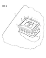
- FIG. 3 shows a portion of the wall 1 of a prosthesis stem in a perspective sectional view.
- the wall piece 2 is inserted.
- the base frame 3 is integrally connected in the direction of the inside of the wall 1 with a flat, substantially rectangular insert 6, which is embedded in the wall 1 approximately parallel to the wall 1.
- the insert 6 also has the passage opening 4, thus also forms a boundary of the passage opening 4.
- the insert 6 protrudes on the side facing away from the passage opening 4 on the base frame 3 addition.
- the insert 6 has a lower thickness than the wall 1 and is perforated to keep a weight of the prosthesis low.
- the insert 6 is used as anchoring of the base frame 3.
- the wall piece 2 has a circumferential base body 11, on which the locking slide 5 is mounted.
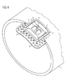
- FIG. 4 shows the region of the wall 1 of a prosthesis stem with a wall piece 2 as in FIG. 3 in a further perspective sectional view with a section through the prosthesis stem perpendicular to the longitudinal axis. Further shows FIG. 3 in that the insert 6 of the base frame 3 is embedded parallel to the wall 1 in the wall 1.
- FIG. 5 shows a transparent view of the wall 1 of a prosthesis stem with the base frame 3 and the passage opening 4.
- the base frame 3 is surrounded by the insert 6.
- the base frame 3 On a side facing away from the body part receiving area, the base frame 3 on sides which extend approximately parallel to the longitudinal axis of the prosthesis shaft, undercuts 9, in which platelets 14 engage for locking a wall piece 2.
- FIG. 6 shows a portion of the wall piece 2 and the base frame 3 in a perspective sectional view, wherein the wall piece 2 is not locked to the base frame 3, but is located outside of the base frame 3.
- the undercut 9 can be seen, in which the projection 8 engages in the locked state.
- the base frame 3 is further in a direction away from the passage opening 4 direction in one piece in the insert 6, which serves as anchoring of the base frame 3 in the wall 1.
- the wall piece 2 On a side facing the base frame 3 of the circumferential base body 11 of the wall piece 2, the wall piece 2 has a sealing ring 7 for further sealing of the area between wall piece 2 and base frame 3 for maintaining a vacuum in the prosthesis stem and against dirt and moisture.
- the wall piece has, on a side facing the body part receiving area, a free space 10 within the circulating basic body 11, which makes it possible to accommodate devices with different functionalities.
- a medical carrier pad with a medicament for delivery to the body part located in the body part receiving region can be arranged.
- a pressure pad, a TENS electrode, a vibrating element, a moisture absorbing material etc. can be arranged in the free space 10.
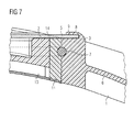
- FIG. 7 shows a transparent sectional view of the wall 1, in which the wall piece 2 is located.
- the wall piece 2 is shown in half.
- the locking slide 5 is in the locked state.
- the small plate 14 is displaced towards the base frame 3, so that the projection 8 of the small plate 14 engages in the rear 9 of the base frame 3.
- the anchoring of the base frame 3 can be seen by means of the insert 6, which runs parallel to and approximately in the middle of the wall 1.
- FIG. 8 shows the wall piece 2 in a perspective view.
- the wall piece 2 has the encircling body 11, which has a circumferential sealing ring 7 approximately at half the height.
- the locking slide 5 which has the two mutually displaceable, flat and lying approximately parallel to the wall plate 14, arranged.
- the projections 8 of the platelets 14 protrude beyond the base body 11 and the sealing ring 7, so that they can engage in the undercuts 9 of the base frame 3. This results in a positive connection between the locking slide 5 and the base frame 3. If the handles 12 are compressed, the platelets 14 move towards each other, and the protrusions 8 are pulled out of the Schuscheidungen 9. This releases the connection between the locking slide 5 and the base frame. 3
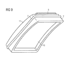
- FIG. 9 shows the wall piece 2 in a perspective bottom view, which shows a part of the body receiving area facing side of the wall piece 2.
- the free space 10 for receiving a device, such as a medical carrier pads.
Landscapes
- Health & Medical Sciences (AREA)
- Animal Behavior & Ethology (AREA)
- Veterinary Medicine (AREA)
- Public Health (AREA)
- General Health & Medical Sciences (AREA)
- Life Sciences & Earth Sciences (AREA)
- Rehabilitation Therapy (AREA)
- Engineering & Computer Science (AREA)
- Biomedical Technology (AREA)
- Nuclear Medicine, Radiotherapy & Molecular Imaging (AREA)
- Radiology & Medical Imaging (AREA)
- Physical Education & Sports Medicine (AREA)
- Pain & Pain Management (AREA)
- Epidemiology (AREA)
- Cardiology (AREA)
- Vascular Medicine (AREA)
- Heart & Thoracic Surgery (AREA)
- Transplantation (AREA)
- Oral & Maxillofacial Surgery (AREA)
- Prostheses (AREA)
Abstract
Die Erfindung betrifft eine Prothese oder Orthese für den Ersatz von äußeren Körperteilen oder Gliedmaßen, beispielsweise nach Amputationen, bzw. zum Stabilisieren, Entlasten, Ruhigstellen und Führen von Gliedmaßen oder des Rumpfs oder zum Korrigieren von Fehlstellungen von Gliedmaßen oder des Rumpfs.The invention relates to a prosthesis or orthosis for the replacement of external body parts or limbs, for example, after amputations, or for stabilizing, relieving, immobilizing and guiding limbs or trunk or for correcting malpositions of limbs or trunk.
Description
Die Erfindung betrifft eine Prothese oder Orthese für den Ersatz von äußeren Körperteilen oder Gliedmaßen, beispielsweise nach Amputationen, bzw. zum Stabilisieren, Entlasten, Ruhigstellen und Führen von Gliedmaßen oder des Rumpfs oder zum Korrigieren von Fehlstellungen von Gliedmaßen oder des Rumpfs.The invention relates to a prosthesis or orthosis for the replacement of external body parts or limbs, for example, after amputations, or for stabilizing, relieving, immobilizing and guiding limbs or trunk or for correcting malpositions of limbs or trunk.
Bei den im Stand der Technik bekannten Prothesen oder Orthesen ist eine Behandlung eines Amputationsstumpfes oder einer mit einer Orthese therapierten Gliedmaße meist nur nach Abnehmen der Prothese oder Orthese, z.B. zur Verabreichung eines Medikaments in das Körpergewebe, möglich. Ist die Prothese oder Orthese an den Amputationsstumpf oder das zu therapierende Körperteil angelegt, überdecken der Prothesenschaft oder die Schalenteile der Orthese den Amputationsstumpf bzw. das Körperteil großflächig, so dass der Stumpf bzw. das Körperteil nachträglich nicht lokal wählbar mit Medikamenten versorgt werden kann.In the case of the prostheses or orthoses known in the prior art, it is usually possible to treat an amputation stump or a limb treated with an orthosis only after removal of the prosthesis or orthosis, eg for administration of a medicament into the body tissue. If the prosthesis or orthosis is applied to the amputation stump or the body part to be treated, the prosthesis socket or the shell parts of the orthosis cover the amputation stump or the body part over a large area, so that the stump or the body part can not subsequently be supplied with drugs locally.
Ferner sind im Stand der Technik Prothesen oder Orthesen bekannt, die über die oben genannten Funktionen, wie den Ersatz oder das Ruhigstellen von Gliedmaßen, hinaus weitere Funktionen besitzen. Beispielsweise ist es möglich in einen Prothesenschaft Kammern zu integrieren, in welchen Medikamentendepots zur Abgabe von Medikamenten an einen Amputationsstumpf eingesetzt sind. Des Weiteren sind Prothesen oder Orthesen bekannt, die im Prothesenschaft angeordnete Heizelemente zur Erwärmung eines Amputationsstumpfes oder Druckelemente zur Stimulation von Akupressurpunkten aufweisen. Andere Prothesen oder Orthesen beinhalten wiederum Sensoren zur Überwachung von Körperzuständen, wie zum Beispiel des Blutdrucks oder der Körpertemperatur.Furthermore, in the prior art prostheses or orthoses are known which have over the above functions, such as the replacement or immobilization of limbs, other functions. For example, it is possible to integrate chambers into a prosthesis shaft in which drug depots are used to deliver medicaments to an amputation stump. Furthermore, prostheses or orthoses are known which have arranged in the prosthesis stem heating elements for heating an amputation stump or pressure elements for the stimulation of acupressure points. Other prostheses or orthoses, in turn, include sensors for monitoring body conditions, such as blood pressure or body temperature.
Die bisher bekannten Prothesen oder Orthesen weisen entweder lediglich eine dieser zusätzlichen Funktionalitäten auf oder müssen für jeden Patienten individuell mit den gewünschten Funktionalitäten ausgestattet werden. Eine nachträgliche Änderung der Funktionalität der Prothese oder Orthese, insbesondere während diese an ein Körperteil angelegt ist, ist dabei nicht mehr möglich, da die entsprechenden Geräte fest in den Prothesenschaft oder die Orthese eingebaut sind.The previously known prostheses or orthoses either have only one of these additional functionalities or have to be individually equipped with the desired functionalities for each patient. A subsequent change in the functionality of the prosthesis or orthosis, especially while this is applied to a body part, is no longer possible, since the corresponding devices are firmly installed in the prosthesis socket or the orthosis.
Ausgehend hiervon ist es eine Aufgabe der vorliegenden Erfindung eine Prothese oder Orthese bereitzustellen, die eine nachträgliche, lokal wählbare Behandlung eines Amputationsstumpfes bzw. eines Körperteils erlaubt sowie eine einfache nachträgliche ein- oder mehrmalige Änderung der Funktionalität ermöglicht.Based on this, it is an object of the present invention to provide a prosthesis or orthosis, which allows a subsequent, locally selectable treatment of an amputation stump or a body part and allows a simple subsequent one or more changes in functionality.
Die Aufgabe wird durch eine Prothese oder Orthese nach Anspruch 1 gelöst. Vorteilhafte Ausgestaltungen der erfindungsgemäßen Prothese oder Orthese werden in den abhängigen Ansprüchen 2 bis 31 beschrieben.The object is achieved by a prosthesis or orthosis according to
Die erfindungsgemäße Prothese oder Orthese weist einen Schaft zur Aufnahme eines Körperteils auf. Der Schaft weist eine einen Körperteilaufnahmebereich begrenzende Wandung auf, wobei ein Teil der Wandung als herausnehmbares Wandstück ausgebildet ist. Das Wandstück weist eine dem Körperteilaufnahmebereich zugewandte Innenseite und eine dem Körperteilaufnahmebereich abgewandte Außenseite auf. Durch das Wandstück ist eine Durchgangsöffnung in der Wandung öffenbar und verschließbar, wobei die Durchgangsöffnung den Körperteilaufnahmebereich mit einem Außenbereich der Prothese oder Orthese verbindet.The prosthesis or orthosis according to the invention has a shaft for receiving a body part. The shank has a wall bounding a body part receiving region, wherein a part of the wall is designed as a removable wall piece. The wall piece has an inner side facing the body part receiving area and an outer side facing away from the body part receiving area. Through the wall piece is a Through opening in the wall can be opened and closed, wherein the passage opening connects the body part receiving area with an outside area of the prosthesis or orthosis.
Das herausnehmbare Wandstück schafft somit einen lokal wählbaren Zugang zum von einer Prothese aufgenommenen Amputationsstumpf bzw. von einer Orthese aufgenommenen Körperteil, sodass der Amputationsstumpf bzw. das Körperteil behandelt werden kann ohne die Prothese oder Orthese abnehmen zu müssen.The removable wall piece thus provides a locally selectable access to the received by a prosthesis amputation stump or received by an orthosis body part, so that the amputation stump or the body part can be treated without having to remove the prosthesis or orthosis.
Das Wandstück ist vorzugsweise gemäß einem an das Wandstück angrenzenden Teil der Wandung gewölbt ausgebildet, so dass sich das Wandstück glatt oder formgerecht in die Wandung des Schaftes einfügt. In diesem Fall fügt sich das Wandstück auch optisch in die Wandung ein, was die Optik des Schaftes verbessert. Ferner wird hierdurch eine glatte Schaftoberfläche erzielt, die den Tragekomfort beispielsweise unter Kleidung erhöht. Des Weiteren kann das Wandstück auch flächig, kreisförmig, quadratisch, rechteckig, vieleckig, rund und/oder oval, auch unabhängig von der Wölbung oder Krümmung eines an das Wandstück angrenzenden Teils der Wandung, ausgebildet sein.The wall piece is preferably arched in accordance with a part of the wall adjoining the wall piece, so that the wall piece fits into the wall of the shank in a smooth or dimensionally appropriate manner. In this case, the wall piece also fits visually into the wall, which improves the appearance of the shaft. Furthermore, this achieves a smooth shaft surface, which increases the wearing comfort, for example, under clothing. Furthermore, the wall piece may also be configured as flat, circular, square, rectangular, polygonal, round and / or oval, also independent of the curvature or curvature of a part of the wall adjoining the wall piece.
Vorzugsweise schließt das Wandstück nahezu oder komplett formschlüssig mit dem an das Wandstück angrenzenden Teil der Wandung ab. Dies verbessert die Optik der Prothese oder Orthese.Preferably, the wall piece closes almost or completely positively with the part of the wall adjacent to the wall piece. This improves the appearance of the prosthesis or orthosis.
Das Wandstück kann ferner eine Dichtung zum luftdichten oder nahezu luftdichten Verschließen der Durchgangsöffnung aufweisen. Auf diese Weise kann nach dem Verschließen der Durchgangsöffnung mit dem Wandstück ein Vakuum im Prothesenschaft aufrecht erhalten werden. Die Dichtung kann auch zur Abdichtung der Durchgangsöffnung gegen Feuchtigkeit und/oder Schmutz dienen. Dies das Eindringen von Schmutz und Feuchtigkeit zwischen Wandstück und Wandung. Die Dichtung kann als ein um das Wandstück umlaufender Dichtring ausgestaltet sein.The wall piece may further comprise a seal for airtight or almost airtight sealing of the through hole. In this way, after closing the passage opening with the wall piece, a vacuum can be maintained in the prosthesis socket. The seal can also serve to seal the passage opening against moisture and / or dirt. This is the penetration of dirt and moisture between wall piece and wall. The seal may be configured as a circumferential around the wall piece sealing ring.
Zur Befestigung des Wandstücks an der Wandung kann die Außenseite des Wandstücks Haken und eine dem Körperteilaufnahmebereich abgewandte Außenseite eines an das Wandstück angrenzenden Teils der Wandung Hinterschneidungen oder Ösen aufweisen, durch welche das Wandstück mit der Wandung verklemmbar ist.For attachment of the wall piece to the wall, the outside of the wall piece can hook and a body part receiving portion facing away from the outside of a wall piece adjacent to the part of the wall Undercuts or eyes have, by which the wall piece can be clamped to the wall.
Alternativ kann die Wandung ein die Durchgangsöffnung umlaufendes Gewinde aufweisen, in das das Wandstück einschraubbar und aus dem das Wandstück herausschraubbar ist.Alternatively, the wall can have a through-opening circumferential thread into which the wall piece can be screwed and out of which the wall piece can be unscrewed.
Das Wandstück kann eine Dicke aufweisen, die kleiner, größer oder gleich einer Dicke eines an das Wandstück angrenzenden Teils der Wandung ist. Ferner kann das Wandstück eine Breite zwischen 2 und 10 cm, vorzugsweise zwischen 4 und 8 cm, bevorzugt von 6 cm, eine Länge zwischen 2 und 10 cm, vorzugsweise zwischen 4 und 8 cm, bevorzugt von 6 cm, und/oder eine Dicke zwischen 0,5 und 5 cm, vorzugsweise zwischen 1 und 3 cm, besonders bevorzugt von 2 cm aufweisen. Im Falle eines runden Wandstücks kann das Wandstück einen Durchmesser zwischen 2 und 10 cm, vorzugsweise zwischen 4 und 8 cm, bevorzugt von 6 cm aufweisen.The wall piece may have a thickness which is smaller, greater than or equal to a thickness of a part of the wall adjoining the wall piece. Furthermore, the wall piece may have a width between 2 and 10 cm, preferably between 4 and 8 cm, preferably 6 cm, a length between 2 and 10 cm, preferably between 4 and 8 cm, preferably 6 cm, and / or a thickness between 0.5 and 5 cm, preferably between 1 and 3 cm, more preferably of 2 cm. In the case of a round wall piece, the wall piece may have a diameter between 2 and 10 cm, preferably between 4 and 8 cm, preferably 6 cm.
Das Wandstück und die Wandung können gleiche und/oder unterschiedliche Materialien aufweisen oder daraus bestehen.The wall piece and the wall may have the same and / or different materials or consist thereof.
In einer vorteilhaften Ausgestaltung der Erfindung kann das Wandstück mit einer oder mit mehreren speziellen Funktionalitäten ausgestattet sein. Zum einen kann auf der Innenseite des Wandstücks ein Druckpolster zur Akupressur eines speziellen Akupressurpunktes oder einer Nervenbahn eines Amputationsstumpfes oder eines Körperteils angebracht sein. Ein derartiges Druckpolster kann auch zur Fixierung der Prothese oder Orthese an dem Körperteil dienen. Das Druckpolster enthält bevorzugt Luft, Schaumstoff, eine Pelotte, ein elastisches Material, ein Material mit einem weichen Shore-Grad und/oder ein rigides Material oder besteht daraus. Eine Oberfläche des Druckpolsters kann glatt, rau und/oder adhäsiv sein und/oder ein Relief und/oder Noppen aufweisen. Die Noppen können dabei vollständig mit Material gefüllt oder hohl gestaltet sein.In an advantageous embodiment of the invention, the wall piece can be equipped with one or more special functionalities. On the one hand, a pressure pad for the acupressure of a specific acupressure point or a nerve tract of an amputation stump or a body part can be attached to the inside of the wall piece. Such a pressure pad can also serve to fix the prosthesis or orthosis to the body part. The pressure pad preferably contains or consists of air, foam, a pad, an elastic material, a soft Shore grade material, and / or a rigid material. A surface of the pressure pad may be smooth, rough and / or adhesive and / or have a relief and / or nubs. The nubs can be completely filled with material or hollow.
Ferner kann auf der Innenseite des Wandstücks ein Medikamentendepot zur Abgabe eines Medikaments an einen Amputationsstumpf oder ein Körperteil angebracht oder in das Wandstück integriert sein. An einem Wandstück können darüberhinaus auch verschiedene Medikamentendepots angebracht oder in das Wandstück integriert sein, wenn verschiedene Medikamente gleichzeitig verabreicht werden sollen.Further, on the inside of the wall piece, a drug depot for dispensing a drug may be attached to an amputation stump or a body part or integrated into the wall piece. On a piece of wall can In addition, several drug depots may be attached or integrated into the wall piece, if different drugs are to be administered simultaneously.
Des Weiteren kann auf der Innenseite des Wandstücks ein Wärme-/KühlElement zur Erwärmung und/oder Kühlung des Körperteils und/oder von arteriellem Blut an einer zentralen Einströmstelle des arteriellen Blutes angebracht oder in das Wandstück integriert sein. Hierdurch kann beispielsweise einem oft beklagten Kältegefühl in einem Amputationsstumpf entgegengewirkt werden.Furthermore, a heating / cooling element for heating and / or cooling the body part and / or arterial blood at a central inflow point of the arterial blood may be attached or integrated into the wall piece on the inside of the wall piece. As a result, for example, an often-deplored sensation of coldness in an amputation stump can be counteracted.
Des Weiteren kann auf der Innenseite des Wandstücks ein eine Feuchtigkeit aufsaugendes Material oder ein elektronisch und/oder mechanisch wirkendes Entfeuchtungselement zur Dehydrierung eines feuchten Innenschaftklimas angebracht oder in das Wandstück integriert sein. Das eine Feuchtigkeit aufsaugende Material kann beispielsweise in Form von Pads am Wandstück angebracht sein.Furthermore, on the inside of the wall piece, a moisture-absorbing material or an electronically and / or mechanically acting dehumidifying element for dehydration of a moist indoor climate can be mounted or integrated into the wall piece. The moisture absorbent material may be attached to the wall piece, for example in the form of pads.
Ferner ist es denkbar, auf der Innenseite des Wandstücks ein Messgerät zur Messung von Körperzuständen, eines Blutdrucks, einer Strömungsgeschwindigkeit von Blut und/oder einer Körpertemperatur anzubringen oder in das Wandstück zu integrieren.Furthermore, it is conceivable to mount on the inside of the wall piece a measuring device for measuring body states, a blood pressure, a flow velocity of blood and / or a body temperature or to integrate them into the wall piece.
Darüberhinaus ist für Langzeitdiagnosen die Abfrage von bionischen Daten interessant. Hierzu kann auf der Innenseite des Wandstücks ein Messgerät zur Erfassung von bionischen Daten, wie z. B. eines Oberflächendruckes an definierten Messpunkten, einer Schaftinnentemperatur und/oder eines Feuchtigkeitsgrades angebracht oder in das Wandstück integriert sein.In addition, the query of bionic data is interesting for long-term diagnoses. For this purpose, on the inside of the wall piece, a measuring device for detecting bionic data, such. As a surface pressure at defined measuring points, a shank interior temperature and / or a degree of moisture or integrated into the wall piece.
In einer weiteren vorteilhaften Ausgestaltung der Erfindung kann auf der Innenseite des Wandstücks ein Permanentmagnet oder ein Elektromagnet zur Erzeugung eines Magnetfeldes angebracht oder in das Wandstück integriert sein. Gepulste elektromagnetische Felder (PEMF) sollen bei bestimmten Frequenzen den Organismus bioenergetisch positiv beeinflussen und die Durchblutung fördern, um den Zellstoffwechsel anzuregen.In a further advantageous embodiment of the invention may be mounted on the inside of the wall piece, a permanent magnet or an electromagnet for generating a magnetic field or integrated into the wall piece. Pulsed electromagnetic fields (PEMF) should have a bioenergetic positive influence on the organism at certain frequencies and promote blood circulation in order to stimulate cell metabolism.
Eine weitere Möglichkeit sieht vor, auf der Innenseite des Wandstücks ein Piezoelement zur elektrischen und/oder mechanischen Stimulation des Körperteils anzubringen oder in das Wandstück zu integrieren.Another possibility provides to install on the inside of the wall piece, a piezoelectric element for electrical and / or mechanical stimulation of the body part or to integrate into the wall piece.
Weiterhin kann auf der Innenseite des Wandstücks ein Vibrationselement angebracht oder in das Wandstück integriert sein, wobei das Vibrationselement mit dem Körperteil in mechanischem Kontakt steht. Das Vibrationselement überträgt mechanische Schwingungen auf das von der Prothese oder Orthese aufgenommene Körperteil. Dies fördert die Relaxierung der Muskulatur und die Durchblutung des Körperteils und reduziert Muskelverspannungen.Furthermore, on the inside of the wall piece, a vibration element may be attached or integrated into the wall piece, wherein the vibration element is in mechanical contact with the body part. The vibrating element transmits mechanical vibrations to the body part received by the prosthesis or orthosis. This promotes the relaxation of the muscles and the blood circulation of the body part and reduces muscle tension.
Ferner kann auf der Innenseite des Wandstücks eine Elektrode zur Abnahme von myoelektrischen Impulsen von dem Körperteil zur Steuerung von mechanischen Gelenken der Prothese oder Orthese angebracht oder in das Wandstück integriert sein.Further, on the inside of the wall piece, an electrode for removing myoelectric pulses from the body part for controlling mechanical joints of the prosthesis or orthosis may be attached or integrated into the wall piece.
Zur Fern-Überwachung der Rehabilitationstherapie oder der Tragezeit kann auf der Innenseite des Wandstücks ein Temperatur- und/oder Bewegungslogger angebracht oder in das Wandstück integriert sein.For remote monitoring of the rehabilitation therapy or the wearing time, a temperature and / or movement logger can be mounted on the inside of the wall piece or integrated into the wall piece.
Eine weitere vorteilhafte Ausgestaltung der Erfindung sieht vor, dass auf der Innenseite des Wandstücks eine TENS-Elektrode oder ein TENS-Gerät angebracht oder in das Wandstück integriert ist, wobei die TENS-Elektrode oder das TENS-Gerät mit dem Körperteil in elektrisch leitendem Kontakt steht. Ein TENS-Gerät dient zur Schmerzbehandlung von Gliedmaßen. Die TENS-Geräte geben über Elektroden einen Reizstrom an die Haut ab. Das Therapieziel ist die Schmerzreduktion durch Verringerung oder Verhinderung der Schmerzweiterleitung an das Gehirn. Ein derartiges TENS-Gerät wird beispielsweise bei der Behandlung des Phantomschmerzes angewandt.A further advantageous embodiment of the invention provides that on the inside of the wall piece, a TENS electrode or a TENS device is mounted or integrated in the wall piece, wherein the TENS electrode or the TENS device is in electrically conductive contact with the body part , A TENS device is used for pain treatment of limbs. The TENS devices deliver an electrical stimulation to the skin via electrodes. The therapeutic goal is to reduce pain by reducing or preventing pain transmission to the brain. Such a TENS device is used, for example, in the treatment of phantom pain.
Des Weiteren kann auf der Innenseite des Wandstücks ein Sensor für eine funktionelle Elektrostimulation des Körperteils, z.B. zur Behandlung nach einem Schlaganfall, angebracht oder in das Wandstück integriert sein.Furthermore, on the inside of the wall piece, a sensor for a functional electrical stimulation of the body part, e.g. for treatment after a stroke, attached or integrated into the wall piece.
Es ist auch vorteilhaft, wenn die Wandung eine Vielzahl von herausnehmbaren Wandstücken aufweist, wobei durch ein Wandstück jeweils eine Durchgangsöffnung öffenbar und verschließbar ist, wobei die Durchgangsöffnungen den Körperteilaufnahmebereich mit einem Außenbereich der Prothese oder Orthese verbinden. In diesem Fall können mehrere verschiedene Stellen des von der Prothese oder der Orthese aufgenommenen Körperteils von außen zugänglich gemacht werden. Außerdem ermöglicht dies verschiedene Wandstücke mit verschiedenen Funktionalitäten auszustatten.It is also advantageous if the wall is a variety of removable Wall pieces, wherein in each case a passage opening can be opened and closed by a wall piece, wherein the passage openings connect the body part receiving area with an outer region of the prosthesis or orthosis. In this case, several different locations of the body part received by the prosthesis or the orthosis can be made accessible from the outside. In addition, this allows different pieces of wall to equip with different functionalities.
Ein oder mehrere oder alle Wandstücke können darüberhinaus auch entlang von Akupunktur-Meridianen und/oder Nervenbahnen des Körperteils angeordnet sein. Durch an den Wandstücken angeordnete Druckpolster oder TENS-Elektroden können diese Akupunktur-Meridiane und/oder Nervenbahnen dann stimuliert und Schmerzen im Körperteil behandelt werden.One or more or all wall pieces may also be arranged along acupuncture meridians and / or nerve tracts of the body part. By arranged on the wall pieces pressure pad or TENS electrodes these acupuncture meridians and / or nerve tracts can then be stimulated and pain in the body part to be treated.
Ferner können ein oder mehrere oder alle Wandstücke entlang von Bereichen zwischen Muskeln des Körperteils angeordnet sein. Werden die Wandstücke dann beispielsweise mit jeweils einem Druckpolster ausgestattet, kann die Prothese oder Orthese an den Muskellücken beispielsweise gegen ein Verdrehen entlang des Umfangs des Körperteils oder ein Verrutschen in Längsrichtung des Körperteils abgestützt und somit der Sitz der Prothese oder Orthese verbessert werden.Further, one or more or all of the wall pieces may be disposed along areas between muscles of the body part. If the wall pieces are then equipped, for example, with a pressure pad in each case, the prosthesis or orthosis can be supported against the muscle gaps, for example against twisting along the circumference of the body part or slippage in the longitudinal direction of the body part, thus improving the fit of the prosthesis or orthosis.
Der Prothesenschaft ist bevorzugt zylinderförmig oder konisch gestaltet und kann einschalig oder auch mehrschalig ausgebildet sein.The prosthesis stem is preferably cylindrical or conical in shape and may be designed as single-shell or multi-shell.
Die hier beschriebene Prothese oder Orthese kann beispielsweise eine Armoder Beinprothese oder -orthese oder ein Rumpfkorsett sein.The prosthesis or orthosis described herein may be, for example, an Arman prosthetic leg or brace or torso corset.
Nachfolgend werden einige vorteilhafte Ausführungsbeispiele einer erfindungsgemäßen Prothese oder Orthese anhand von Figuren genauer beschrieben. Die beschriebenen Merkmale sind jedoch nicht nur in Kombination der offenbarten Ausführungsbeispiele möglich, sondern können auch unabhängig vom konkreten Ausführungsbeispiel in verschiedenen Kombinationen realisiert sein. Ferner bezeichnen gleiche oder ähnlichen in den Figuren verwendete Bezugszeichen gleiche oder ähnliche Merkmale.Hereinafter, some advantageous embodiments of a prosthesis or orthosis according to the invention will be described in more detail with reference to figures. However, the features described are not only possible in combination of the disclosed embodiments, but can also be realized independently of the specific embodiment in various combinations. Further, the same or similar reference numerals used in the figures indicate the same or similar features.
Es zeigen
Figur 1- einen erfindungsgemäßen Prothesenschaft, wobei sich das Wandstück in geöffneter Position befindet, in einer Perspektivansicht,
Figur 2- den erfindungsgemäßen Prothesenschaft aus
Figur 1 , wobei sich das Wandstück in geschlossener Position befindet, in einer Perspektivansicht, Figur 3- einen erfindungsgemäßen Prothesenschaft mit einem Wandstück in einer perspektivischen Schnittansicht,
Figur 4- einen erfindungsgemäßen Prothesenschaft mit einem Wandstück in einer weiteren perspektivischen Schnittansicht,
Figur 5- eine Wandung eines erfindungsgemäßen Prothesenschafts mit einem Grundrahmen für das Wandstück in einer transparenten Ansicht,
Figur 6- eine perspektivische Schnittansicht eines erfindungsgemäßen Wandstücks und eines dazugehörigen Grundrahmens,
Figur 7- eine transparente Schnittansicht eines erfindungsgemäßen Wandstücks und eines dazugehörigen Grundrahmens,
Figur 8- eine Perspektivansicht eines erfindungsgemäßen Wandstücks und
Figur 9- eine weitere Perspektivansicht eines erfindungsgemäßen Wandstücks.
- FIG. 1
- a prosthesis socket according to the invention, wherein the wall piece is in the open position, in a perspective view,
- FIG. 2
- the prosthesis stem according to the invention
FIG. 1 , wherein the wall piece is in the closed position, in a perspective view, - FIG. 3
- a prosthesis stem according to the invention with a wall piece in a perspective sectional view,
- FIG. 4
- a prosthesis stem according to the invention with a wall piece in a further perspective sectional view,
- FIG. 5
- a wall of a prosthesis stem according to the invention with a base frame for the wall piece in a transparent view,
- FIG. 6
- a perspective sectional view of a wall piece according to the invention and an associated base frame,
- FIG. 7
- a transparent sectional view of a wall piece according to the invention and an associated base frame,
- FIG. 8
- a perspective view of a wall piece according to the invention and
- FIG. 9
- another perspective view of a wall piece according to the invention.
Es werden die folgenden Bezugszeichen verwendet:
- 1
- Wandung
- 2
- Wandstück
- 3
- Grundrahmen
- 4
- Durchgangsöffnung
- 5
- Verriegelungsschieber
- 6
- Einsatz
- 7
- Dichtring
- 8
- Überstand
- 9
- Hinterschneidung
- 10
- Freiraum
- 11
- Grundkörper
- 12
- Griffe
- 13
- Innenseite
- 14
- Plättchen
- 15
- Öffnung
- 1
- wall
- 2
- wall piece
- 3
- base frame
- 4
- Through opening
- 5
- locking slide
- 6
- commitment
- 7
- seal
- 8th
- Got over
- 9
- undercut
- 10
- free space
- 11
- body
- 12
- handles
- 13
- inside
- 14
- Tile
- 15
- opening
In
Claims (16)
dadurch gekennzeichnet, dass
ein Teil der Wandung als herausnehmbares Wandstück mit einer dem Körperteilaufnahmebereich zugewandten Innenseite und einer dem Körperteilaufnahmebereich abgewandten Außenseite ausgebildet ist, durch welches eine Durchgangsöffnung in der Wandung öffenbar und verschließbar ist, wobei die Durchgangsöffnung den Körperteilaufnahmebereich mit einem Außenbereich der Prothese oder Orthese verbindet.A prosthesis or orthosis having a shaft for receiving a body part, said shaft having a wall defining a body part receiving area,
characterized in that
a part of the wall is designed as a removable wall piece with an inner side facing the body part receiving area and an outer side facing away from the body part receiving area, through which a through opening in the wall can be opened and closed, the through opening connecting the body part receiving area to an outer area of the prosthesis or orthosis.
Applications Claiming Priority (1)
| Application Number | Priority Date | Filing Date | Title |
|---|---|---|---|
| DE202014004380.9U DE202014004380U1 (en) | 2014-05-26 | 2014-05-26 | Prosthesis or orthosis with removable wall piece |
Publications (3)
| Publication Number | Publication Date |
|---|---|
| EP2949294A2 true EP2949294A2 (en) | 2015-12-02 |
| EP2949294A3 EP2949294A3 (en) | 2016-03-30 |
| EP2949294B1 EP2949294B1 (en) | 2019-02-13 |
Family
ID=51353284
Family Applications (1)
| Application Number | Title | Priority Date | Filing Date |
|---|---|---|---|
| EP15168896.7A Not-in-force EP2949294B1 (en) | 2014-05-26 | 2015-05-22 | Prosthesis or orthesis with removable wall piece |
Country Status (2)
| Country | Link |
|---|---|
| EP (1) | EP2949294B1 (en) |
| DE (1) | DE202014004380U1 (en) |
Families Citing this family (2)
| Publication number | Priority date | Publication date | Assignee | Title |
|---|---|---|---|---|
| DE102014221474A1 (en) * | 2014-10-22 | 2016-04-28 | Pohlig Gmbh | Heating / cooling element |
| DE102017129930B4 (en) * | 2017-12-14 | 2019-07-04 | Ottobock Se & Co. Kgaa | Prosthetic socket system |
Family Cites Families (5)
| Publication number | Priority date | Publication date | Assignee | Title |
|---|---|---|---|---|
| US2533404A (en) * | 1948-08-13 | 1950-12-12 | Sharp Oscar | Artificial limb and valve therefor |
| DE9419211U1 (en) * | 1994-11-30 | 1995-02-02 | Carstens Felix | Artificial link |
| US20040260402A1 (en) * | 2003-06-20 | 2004-12-23 | Baldini Steven E. | Method of manufacturing a socket portion of a prosthetic limb |
| DE202006007460U1 (en) * | 2006-05-09 | 2007-09-13 | Otto Bock Healthcare Products Gmbh | Prosthesis inner shaft system |
| WO2014018573A1 (en) * | 2012-07-23 | 2014-01-30 | The Ohio Willow Wood Company | Polymeric prosthetic and orthotic devices with heat control capabilities |
-
2014
- 2014-05-26 DE DE202014004380.9U patent/DE202014004380U1/en not_active Expired - Lifetime
-
2015
- 2015-05-22 EP EP15168896.7A patent/EP2949294B1/en not_active Not-in-force
Non-Patent Citations (1)
| Title |
|---|
| None |
Also Published As
| Publication number | Publication date |
|---|---|
| DE202014004380U1 (en) | 2014-07-28 |
| EP2949294B1 (en) | 2019-02-13 |
| EP2949294A3 (en) | 2016-03-30 |
Similar Documents
| Publication | Publication Date | Title |
|---|---|---|
| DE102011018470B4 (en) | Bandage and electrode system | |
| DE10036102B4 (en) | Apparatus for treating body tissues with electricity or medication | |
| DE60215130T2 (en) | METHOD AND DEVICE FOR PERMANENTLY CHANGING A NEURAL FUNCTION OF A PATIENT | |
| DE69827463T2 (en) | Device for enlarging tissue | |
| WO2012156052A2 (en) | Stimulation device | |
| EP2026872A1 (en) | Device for transcutaneous application of a stimulus or for transcutaneous recording of a parameter | |
| DE102006026288A1 (en) | Bone conduction hearing aid is held by U arranged magnet pair with open end facing magnets implanted in skull | |
| EP3355987B1 (en) | Magnetic stimulation device | |
| EP2949294B1 (en) | Prosthesis or orthesis with removable wall piece | |
| EP2735290B1 (en) | Prosthesis or orthosis | |
| WO2006005298A1 (en) | Laser needle for performing a combined laser needle/electric acupuncture | |
| DE102016107779A1 (en) | Orthosis joint, modular system for forming a orthotic joint and use thereof | |
| DE202005009361U1 (en) | Bone conduction hearing aid is held by U arranged magnet pair with open end facing magnets implanted in skull | |
| EP2735291B1 (en) | Prosthesis or orthosis | |
| EP3551141B1 (en) | Device for the external application of a local compressive force below the costal arch of a patient to reduce the stomach volume | |
| WO1997038751A1 (en) | Transcutaneous nerve stimulator | |
| EP3634323B1 (en) | Device for use as a therapeutic means in therapeutic treatment of camptocormia | |
| DE202015105668U1 (en) | Bandage for a joint of the human body and Pelottenelement | |
| WO2005089862A1 (en) | Device for submental electrostimulation of the suprahyoidal muscles | |
| DE202016101465U1 (en) | Device for simultaneous cupping and color light therapy | |
| DE202011107938U1 (en) | Device for stimulating the neck muscles and nerves in the neck | |
| DE102004039350B4 (en) | Device for influencing brain functions of a human | |
| DE102020113639A1 (en) | Device for receiving a limb stump of a patient | |
| DE202020103850U1 (en) | Garment for massage and stimulation of the lymph flow | |
| EP4312939A1 (en) | Device for the physiotherapeutic treatment of the human body, consisting of two discs and a kinesiology tape between same, and method for the physiotherapeutic treatment of the human body |
Legal Events
| Date | Code | Title | Description |
|---|---|---|---|
| AK | Designated contracting states |
Kind code of ref document: A2 Designated state(s): AL AT BE BG CH CY CZ DE DK EE ES FI FR GB GR HR HU IE IS IT LI LT LU LV MC MK MT NL NO PL PT RO RS SE SI SK SM TR |
|
| AX | Request for extension of the european patent |
Extension state: BA ME |
|
| PUAI | Public reference made under article 153(3) epc to a published international application that has entered the european phase |
Free format text: ORIGINAL CODE: 0009012 |
|
| PUAL | Search report despatched |
Free format text: ORIGINAL CODE: 0009013 |
|
| AK | Designated contracting states |
Kind code of ref document: A3 Designated state(s): AL AT BE BG CH CY CZ DE DK EE ES FI FR GB GR HR HU IE IS IT LI LT LU LV MC MK MT NL NO PL PT RO RS SE SI SK SM TR |
|
| AX | Request for extension of the european patent |
Extension state: BA ME |
|
| RIC1 | Information provided on ipc code assigned before grant |
Ipc: A61F 2/80 20060101AFI20160223BHEP |
|
| 17P | Request for examination filed |
Effective date: 20160914 |
|
| RBV | Designated contracting states (corrected) |
Designated state(s): AL AT BE BG CH CY CZ DE DK EE ES FI FR GB GR HR HU IE IS IT LI LT LU LV MC MK MT NL NO PL PT RO RS SE SI SK SM TR |
|
| STAA | Information on the status of an ep patent application or granted ep patent |
Free format text: STATUS: EXAMINATION IS IN PROGRESS |
|
| 17Q | First examination report despatched |
Effective date: 20170403 |
|
| GRAP | Despatch of communication of intention to grant a patent |
Free format text: ORIGINAL CODE: EPIDOSNIGR1 |
|
| STAA | Information on the status of an ep patent application or granted ep patent |
Free format text: STATUS: GRANT OF PATENT IS INTENDED |
|
| INTG | Intention to grant announced |
Effective date: 20180919 |
|
| GRAS | Grant fee paid |
Free format text: ORIGINAL CODE: EPIDOSNIGR3 |
|
| GRAA | (expected) grant |
Free format text: ORIGINAL CODE: 0009210 |
|
| STAA | Information on the status of an ep patent application or granted ep patent |
Free format text: STATUS: THE PATENT HAS BEEN GRANTED |
|
| AK | Designated contracting states |
Kind code of ref document: B1 Designated state(s): AL AT BE BG CH CY CZ DE DK EE ES FI FR GB GR HR HU IE IS IT LI LT LU LV MC MK MT NL NO PL PT RO RS SE SI SK SM TR |
|
| REG | Reference to a national code |
Ref country code: GB Ref legal event code: FG4D Free format text: NOT ENGLISH |
|
| REG | Reference to a national code |
Ref country code: CH Ref legal event code: EP Ref country code: AT Ref legal event code: REF Ref document number: 1095776 Country of ref document: AT Kind code of ref document: T Effective date: 20190215 |
|
| REG | Reference to a national code |
Ref country code: IE Ref legal event code: FG4D Free format text: LANGUAGE OF EP DOCUMENT: GERMAN |
|
| REG | Reference to a national code |
Ref country code: DE Ref legal event code: R096 Ref document number: 502015007931 Country of ref document: DE |
|
| REG | Reference to a national code |
Ref country code: LT Ref legal event code: MG4D |
|
| REG | Reference to a national code |
Ref country code: NL Ref legal event code: MP Effective date: 20190213 |
|
| PG25 | Lapsed in a contracting state [announced via postgrant information from national office to epo] |
Ref country code: LT Free format text: LAPSE BECAUSE OF FAILURE TO SUBMIT A TRANSLATION OF THE DESCRIPTION OR TO PAY THE FEE WITHIN THE PRESCRIBED TIME-LIMIT Effective date: 20190213 Ref country code: NO Free format text: LAPSE BECAUSE OF FAILURE TO SUBMIT A TRANSLATION OF THE DESCRIPTION OR TO PAY THE FEE WITHIN THE PRESCRIBED TIME-LIMIT Effective date: 20190513 Ref country code: NL Free format text: LAPSE BECAUSE OF FAILURE TO SUBMIT A TRANSLATION OF THE DESCRIPTION OR TO PAY THE FEE WITHIN THE PRESCRIBED TIME-LIMIT Effective date: 20190213 Ref country code: PT Free format text: LAPSE BECAUSE OF FAILURE TO SUBMIT A TRANSLATION OF THE DESCRIPTION OR TO PAY THE FEE WITHIN THE PRESCRIBED TIME-LIMIT Effective date: 20190613 Ref country code: SE Free format text: LAPSE BECAUSE OF FAILURE TO SUBMIT A TRANSLATION OF THE DESCRIPTION OR TO PAY THE FEE WITHIN THE PRESCRIBED TIME-LIMIT Effective date: 20190213 Ref country code: FI Free format text: LAPSE BECAUSE OF FAILURE TO SUBMIT A TRANSLATION OF THE DESCRIPTION OR TO PAY THE FEE WITHIN THE PRESCRIBED TIME-LIMIT Effective date: 20190213 |
|
| PG25 | Lapsed in a contracting state [announced via postgrant information from national office to epo] |
Ref country code: LV Free format text: LAPSE BECAUSE OF FAILURE TO SUBMIT A TRANSLATION OF THE DESCRIPTION OR TO PAY THE FEE WITHIN THE PRESCRIBED TIME-LIMIT Effective date: 20190213 Ref country code: RS Free format text: LAPSE BECAUSE OF FAILURE TO SUBMIT A TRANSLATION OF THE DESCRIPTION OR TO PAY THE FEE WITHIN THE PRESCRIBED TIME-LIMIT Effective date: 20190213 Ref country code: BG Free format text: LAPSE BECAUSE OF FAILURE TO SUBMIT A TRANSLATION OF THE DESCRIPTION OR TO PAY THE FEE WITHIN THE PRESCRIBED TIME-LIMIT Effective date: 20190513 Ref country code: GR Free format text: LAPSE BECAUSE OF FAILURE TO SUBMIT A TRANSLATION OF THE DESCRIPTION OR TO PAY THE FEE WITHIN THE PRESCRIBED TIME-LIMIT Effective date: 20190514 Ref country code: IS Free format text: LAPSE BECAUSE OF FAILURE TO SUBMIT A TRANSLATION OF THE DESCRIPTION OR TO PAY THE FEE WITHIN THE PRESCRIBED TIME-LIMIT Effective date: 20190613 Ref country code: HR Free format text: LAPSE BECAUSE OF FAILURE TO SUBMIT A TRANSLATION OF THE DESCRIPTION OR TO PAY THE FEE WITHIN THE PRESCRIBED TIME-LIMIT Effective date: 20190213 |
|
| PG25 | Lapsed in a contracting state [announced via postgrant information from national office to epo] |
Ref country code: ES Free format text: LAPSE BECAUSE OF FAILURE TO SUBMIT A TRANSLATION OF THE DESCRIPTION OR TO PAY THE FEE WITHIN THE PRESCRIBED TIME-LIMIT Effective date: 20190213 Ref country code: DK Free format text: LAPSE BECAUSE OF FAILURE TO SUBMIT A TRANSLATION OF THE DESCRIPTION OR TO PAY THE FEE WITHIN THE PRESCRIBED TIME-LIMIT Effective date: 20190213 Ref country code: AL Free format text: LAPSE BECAUSE OF FAILURE TO SUBMIT A TRANSLATION OF THE DESCRIPTION OR TO PAY THE FEE WITHIN THE PRESCRIBED TIME-LIMIT Effective date: 20190213 Ref country code: SK Free format text: LAPSE BECAUSE OF FAILURE TO SUBMIT A TRANSLATION OF THE DESCRIPTION OR TO PAY THE FEE WITHIN THE PRESCRIBED TIME-LIMIT Effective date: 20190213 Ref country code: IT Free format text: LAPSE BECAUSE OF FAILURE TO SUBMIT A TRANSLATION OF THE DESCRIPTION OR TO PAY THE FEE WITHIN THE PRESCRIBED TIME-LIMIT Effective date: 20190213 Ref country code: EE Free format text: LAPSE BECAUSE OF FAILURE TO SUBMIT A TRANSLATION OF THE DESCRIPTION OR TO PAY THE FEE WITHIN THE PRESCRIBED TIME-LIMIT Effective date: 20190213 Ref country code: CZ Free format text: LAPSE BECAUSE OF FAILURE TO SUBMIT A TRANSLATION OF THE DESCRIPTION OR TO PAY THE FEE WITHIN THE PRESCRIBED TIME-LIMIT Effective date: 20190213 Ref country code: RO Free format text: LAPSE BECAUSE OF FAILURE TO SUBMIT A TRANSLATION OF THE DESCRIPTION OR TO PAY THE FEE WITHIN THE PRESCRIBED TIME-LIMIT Effective date: 20190213 |
|
| REG | Reference to a national code |
Ref country code: DE Ref legal event code: R097 Ref document number: 502015007931 Country of ref document: DE |
|
| PG25 | Lapsed in a contracting state [announced via postgrant information from national office to epo] |
Ref country code: SM Free format text: LAPSE BECAUSE OF FAILURE TO SUBMIT A TRANSLATION OF THE DESCRIPTION OR TO PAY THE FEE WITHIN THE PRESCRIBED TIME-LIMIT Effective date: 20190213 Ref country code: PL Free format text: LAPSE BECAUSE OF FAILURE TO SUBMIT A TRANSLATION OF THE DESCRIPTION OR TO PAY THE FEE WITHIN THE PRESCRIBED TIME-LIMIT Effective date: 20190213 |
|
| PLBE | No opposition filed within time limit |
Free format text: ORIGINAL CODE: 0009261 |
|
| STAA | Information on the status of an ep patent application or granted ep patent |
Free format text: STATUS: NO OPPOSITION FILED WITHIN TIME LIMIT |
|
| REG | Reference to a national code |
Ref country code: CH Ref legal event code: PL |
|
| 26N | No opposition filed |
Effective date: 20191114 |
|
| GBPC | Gb: european patent ceased through non-payment of renewal fee |
Effective date: 20190522 |
|
| PG25 | Lapsed in a contracting state [announced via postgrant information from national office to epo] |
Ref country code: MC Free format text: LAPSE BECAUSE OF FAILURE TO SUBMIT A TRANSLATION OF THE DESCRIPTION OR TO PAY THE FEE WITHIN THE PRESCRIBED TIME-LIMIT Effective date: 20190213 Ref country code: LI Free format text: LAPSE BECAUSE OF NON-PAYMENT OF DUE FEES Effective date: 20190531 Ref country code: CH Free format text: LAPSE BECAUSE OF NON-PAYMENT OF DUE FEES Effective date: 20190531 |
|
| REG | Reference to a national code |
Ref country code: BE Ref legal event code: MM Effective date: 20190531 |
|
| PG25 | Lapsed in a contracting state [announced via postgrant information from national office to epo] |
Ref country code: LU Free format text: LAPSE BECAUSE OF NON-PAYMENT OF DUE FEES Effective date: 20190522 Ref country code: SI Free format text: LAPSE BECAUSE OF FAILURE TO SUBMIT A TRANSLATION OF THE DESCRIPTION OR TO PAY THE FEE WITHIN THE PRESCRIBED TIME-LIMIT Effective date: 20190213 |
|
| PG25 | Lapsed in a contracting state [announced via postgrant information from national office to epo] |
Ref country code: TR Free format text: LAPSE BECAUSE OF FAILURE TO SUBMIT A TRANSLATION OF THE DESCRIPTION OR TO PAY THE FEE WITHIN THE PRESCRIBED TIME-LIMIT Effective date: 20190213 |
|
| PG25 | Lapsed in a contracting state [announced via postgrant information from national office to epo] |
Ref country code: GB Free format text: LAPSE BECAUSE OF NON-PAYMENT OF DUE FEES Effective date: 20190522 Ref country code: IE Free format text: LAPSE BECAUSE OF NON-PAYMENT OF DUE FEES Effective date: 20190522 |
|
| PG25 | Lapsed in a contracting state [announced via postgrant information from national office to epo] |
Ref country code: BE Free format text: LAPSE BECAUSE OF NON-PAYMENT OF DUE FEES Effective date: 20190531 |
|
| PG25 | Lapsed in a contracting state [announced via postgrant information from national office to epo] |
Ref country code: FR Free format text: LAPSE BECAUSE OF NON-PAYMENT OF DUE FEES Effective date: 20190531 |
|
| PGFP | Annual fee paid to national office [announced via postgrant information from national office to epo] |
Ref country code: DE Payment date: 20200519 Year of fee payment: 6 |
|
| PG25 | Lapsed in a contracting state [announced via postgrant information from national office to epo] |
Ref country code: CY Free format text: LAPSE BECAUSE OF FAILURE TO SUBMIT A TRANSLATION OF THE DESCRIPTION OR TO PAY THE FEE WITHIN THE PRESCRIBED TIME-LIMIT Effective date: 20190213 |
|
| REG | Reference to a national code |
Ref country code: AT Ref legal event code: MM01 Ref document number: 1095776 Country of ref document: AT Kind code of ref document: T Effective date: 20200522 |
|
| PG25 | Lapsed in a contracting state [announced via postgrant information from national office to epo] |
Ref country code: MT Free format text: LAPSE BECAUSE OF FAILURE TO SUBMIT A TRANSLATION OF THE DESCRIPTION OR TO PAY THE FEE WITHIN THE PRESCRIBED TIME-LIMIT Effective date: 20190213 Ref country code: HU Free format text: LAPSE BECAUSE OF FAILURE TO SUBMIT A TRANSLATION OF THE DESCRIPTION OR TO PAY THE FEE WITHIN THE PRESCRIBED TIME-LIMIT; INVALID AB INITIO Effective date: 20150522 |
|
| PG25 | Lapsed in a contracting state [announced via postgrant information from national office to epo] |
Ref country code: AT Free format text: LAPSE BECAUSE OF NON-PAYMENT OF DUE FEES Effective date: 20200522 |
|
| REG | Reference to a national code |
Ref country code: DE Ref legal event code: R119 Ref document number: 502015007931 Country of ref document: DE |
|
| PG25 | Lapsed in a contracting state [announced via postgrant information from national office to epo] |
Ref country code: DE Free format text: LAPSE BECAUSE OF NON-PAYMENT OF DUE FEES Effective date: 20211201 |
|
| PG25 | Lapsed in a contracting state [announced via postgrant information from national office to epo] |
Ref country code: MK Free format text: LAPSE BECAUSE OF FAILURE TO SUBMIT A TRANSLATION OF THE DESCRIPTION OR TO PAY THE FEE WITHIN THE PRESCRIBED TIME-LIMIT Effective date: 20190213 |
|
| P01 | Opt-out of the competence of the unified patent court (upc) registered |
Effective date: 20230526 |