EP2946846A1 - Tool changing device for a forming press - Google Patents
Tool changing device for a forming press Download PDFInfo
- Publication number
- EP2946846A1 EP2946846A1 EP14001816.9A EP14001816A EP2946846A1 EP 2946846 A1 EP2946846 A1 EP 2946846A1 EP 14001816 A EP14001816 A EP 14001816A EP 2946846 A1 EP2946846 A1 EP 2946846A1
- Authority
- EP
- European Patent Office
- Prior art keywords
- tool
- changing device
- tool changing
- forming
- push chain
- Prior art date
- Legal status (The legal status is an assumption and is not a legal conclusion. Google has not performed a legal analysis and makes no representation as to the accuracy of the status listed.)
- Granted
Links
Images


Classifications
-
- B—PERFORMING OPERATIONS; TRANSPORTING
- B21—MECHANICAL METAL-WORKING WITHOUT ESSENTIALLY REMOVING MATERIAL; PUNCHING METAL
- B21D—WORKING OR PROCESSING OF SHEET METAL OR METAL TUBES, RODS OR PROFILES WITHOUT ESSENTIALLY REMOVING MATERIAL; PUNCHING METAL
- B21D5/00—Bending sheet metal along straight lines, e.g. to form simple curves
- B21D5/02—Bending sheet metal along straight lines, e.g. to form simple curves on press brakes without making use of clamping means
- B21D5/0209—Tools therefor
- B21D5/0254—Tool exchanging
-
- B—PERFORMING OPERATIONS; TRANSPORTING
- B30—PRESSES
- B30B—PRESSES IN GENERAL
- B30B15/00—Details of, or accessories for, presses; Auxiliary measures in connection with pressing
- B30B15/02—Dies; Inserts therefor; Mounting thereof; Moulds
- B30B15/028—Loading or unloading of dies, platens or press rams
-
- B—PERFORMING OPERATIONS; TRANSPORTING
- B21—MECHANICAL METAL-WORKING WITHOUT ESSENTIALLY REMOVING MATERIAL; PUNCHING METAL
- B21D—WORKING OR PROCESSING OF SHEET METAL OR METAL TUBES, RODS OR PROFILES WITHOUT ESSENTIALLY REMOVING MATERIAL; PUNCHING METAL
- B21D37/00—Tools as parts of machines covered by this subclass
- B21D37/04—Movable or exchangeable mountings for tools
-
- B—PERFORMING OPERATIONS; TRANSPORTING
- B21—MECHANICAL METAL-WORKING WITHOUT ESSENTIALLY REMOVING MATERIAL; PUNCHING METAL
- B21D—WORKING OR PROCESSING OF SHEET METAL OR METAL TUBES, RODS OR PROFILES WITHOUT ESSENTIALLY REMOVING MATERIAL; PUNCHING METAL
- B21D37/00—Tools as parts of machines covered by this subclass
- B21D37/14—Particular arrangements for handling and holding in place complete dies
- B21D37/145—Die storage magazines
-
- B—PERFORMING OPERATIONS; TRANSPORTING
- B21—MECHANICAL METAL-WORKING WITHOUT ESSENTIALLY REMOVING MATERIAL; PUNCHING METAL
- B21D—WORKING OR PROCESSING OF SHEET METAL OR METAL TUBES, RODS OR PROFILES WITHOUT ESSENTIALLY REMOVING MATERIAL; PUNCHING METAL
- B21D5/00—Bending sheet metal along straight lines, e.g. to form simple curves
- B21D5/02—Bending sheet metal along straight lines, e.g. to form simple curves on press brakes without making use of clamping means
-
- B—PERFORMING OPERATIONS; TRANSPORTING
- B23—MACHINE TOOLS; METAL-WORKING NOT OTHERWISE PROVIDED FOR
- B23Q—DETAILS, COMPONENTS, OR ACCESSORIES FOR MACHINE TOOLS, e.g. ARRANGEMENTS FOR COPYING OR CONTROLLING; MACHINE TOOLS IN GENERAL CHARACTERISED BY THE CONSTRUCTION OF PARTICULAR DETAILS OR COMPONENTS; COMBINATIONS OR ASSOCIATIONS OF METAL-WORKING MACHINES, NOT DIRECTED TO A PARTICULAR RESULT
- B23Q11/00—Accessories fitted to machine tools for keeping tools or parts of the machine in good working condition or for cooling work; Safety devices specially combined with or arranged in, or specially adapted for use in connection with, machine tools
- B23Q11/0078—Safety devices protecting the operator, e.g. against accident or noise
- B23Q11/0082—Safety devices protecting the operator, e.g. against accident or noise by determining whether the operator is in a dangerous position
-
- B—PERFORMING OPERATIONS; TRANSPORTING
- B23—MACHINE TOOLS; METAL-WORKING NOT OTHERWISE PROVIDED FOR
- B23Q—DETAILS, COMPONENTS, OR ACCESSORIES FOR MACHINE TOOLS, e.g. ARRANGEMENTS FOR COPYING OR CONTROLLING; MACHINE TOOLS IN GENERAL CHARACTERISED BY THE CONSTRUCTION OF PARTICULAR DETAILS OR COMPONENTS; COMBINATIONS OR ASSOCIATIONS OF METAL-WORKING MACHINES, NOT DIRECTED TO A PARTICULAR RESULT
- B23Q3/00—Devices holding, supporting, or positioning work or tools, of a kind normally removable from the machine
- B23Q3/155—Arrangements for automatic insertion or removal of tools, e.g. combined with manual handling
- B23Q3/1556—Arrangements for automatic insertion or removal of tools, e.g. combined with manual handling of non-rotary tools
- B23Q3/15573—Arrangements for automatic insertion or removal of tools, e.g. combined with manual handling of non-rotary tools the tool being taken from a storage device and transferred to a tool holder by means of transfer devices
-
- B—PERFORMING OPERATIONS; TRANSPORTING
- B23—MACHINE TOOLS; METAL-WORKING NOT OTHERWISE PROVIDED FOR
- B23Q—DETAILS, COMPONENTS, OR ACCESSORIES FOR MACHINE TOOLS, e.g. ARRANGEMENTS FOR COPYING OR CONTROLLING; MACHINE TOOLS IN GENERAL CHARACTERISED BY THE CONSTRUCTION OF PARTICULAR DETAILS OR COMPONENTS; COMBINATIONS OR ASSOCIATIONS OF METAL-WORKING MACHINES, NOT DIRECTED TO A PARTICULAR RESULT
- B23Q3/00—Devices holding, supporting, or positioning work or tools, of a kind normally removable from the machine
- B23Q3/155—Arrangements for automatic insertion or removal of tools, e.g. combined with manual handling
- B23Q3/157—Arrangements for automatic insertion or removal of tools, e.g. combined with manual handling of rotary tools
- B23Q3/15713—Arrangements for automatic insertion or removal of tools, e.g. combined with manual handling of rotary tools a transfer device taking a single tool from a storage device and inserting it in a spindle
- B23Q3/1572—Arrangements for automatic insertion or removal of tools, e.g. combined with manual handling of rotary tools a transfer device taking a single tool from a storage device and inserting it in a spindle the storage device comprising rotating or circulating storing means
- B23Q3/15722—Rotary discs or drums
-
- B—PERFORMING OPERATIONS; TRANSPORTING
- B21—MECHANICAL METAL-WORKING WITHOUT ESSENTIALLY REMOVING MATERIAL; PUNCHING METAL
- B21D—WORKING OR PROCESSING OF SHEET METAL OR METAL TUBES, RODS OR PROFILES WITHOUT ESSENTIALLY REMOVING MATERIAL; PUNCHING METAL
- B21D55/00—Safety devices protecting the machine or the operator, specially adapted for apparatus or machines dealt with in this subclass
-
- B—PERFORMING OPERATIONS; TRANSPORTING
- B23—MACHINE TOOLS; METAL-WORKING NOT OTHERWISE PROVIDED FOR
- B23Q—DETAILS, COMPONENTS, OR ACCESSORIES FOR MACHINE TOOLS, e.g. ARRANGEMENTS FOR COPYING OR CONTROLLING; MACHINE TOOLS IN GENERAL CHARACTERISED BY THE CONSTRUCTION OF PARTICULAR DETAILS OR COMPONENTS; COMBINATIONS OR ASSOCIATIONS OF METAL-WORKING MACHINES, NOT DIRECTED TO A PARTICULAR RESULT
- B23Q3/00—Devices holding, supporting, or positioning work or tools, of a kind normally removable from the machine
- B23Q3/155—Arrangements for automatic insertion or removal of tools, e.g. combined with manual handling
- B23Q3/1552—Arrangements for automatic insertion or removal of tools, e.g. combined with manual handling parts of devices for automatically inserting or removing tools
- B23Q3/15526—Storage devices; Drive mechanisms therefor
- B23Q3/15539—Plural magazines, e.g. involving tool transfer from one magazine to another
-
- B—PERFORMING OPERATIONS; TRANSPORTING
- B23—MACHINE TOOLS; METAL-WORKING NOT OTHERWISE PROVIDED FOR
- B23Q—DETAILS, COMPONENTS, OR ACCESSORIES FOR MACHINE TOOLS, e.g. ARRANGEMENTS FOR COPYING OR CONTROLLING; MACHINE TOOLS IN GENERAL CHARACTERISED BY THE CONSTRUCTION OF PARTICULAR DETAILS OR COMPONENTS; COMBINATIONS OR ASSOCIATIONS OF METAL-WORKING MACHINES, NOT DIRECTED TO A PARTICULAR RESULT
- B23Q3/00—Devices holding, supporting, or positioning work or tools, of a kind normally removable from the machine
- B23Q3/155—Arrangements for automatic insertion or removal of tools, e.g. combined with manual handling
- B23Q3/1552—Arrangements for automatic insertion or removal of tools, e.g. combined with manual handling parts of devices for automatically inserting or removing tools
- B23Q3/15546—Devices for recognizing tools in a storage device, e.g. coding devices
-
- Y—GENERAL TAGGING OF NEW TECHNOLOGICAL DEVELOPMENTS; GENERAL TAGGING OF CROSS-SECTIONAL TECHNOLOGIES SPANNING OVER SEVERAL SECTIONS OF THE IPC; TECHNICAL SUBJECTS COVERED BY FORMER USPC CROSS-REFERENCE ART COLLECTIONS [XRACs] AND DIGESTS
- Y10—TECHNICAL SUBJECTS COVERED BY FORMER USPC
- Y10T—TECHNICAL SUBJECTS COVERED BY FORMER US CLASSIFICATION
- Y10T483/00—Tool changing
- Y10T483/10—Process
-
- Y—GENERAL TAGGING OF NEW TECHNOLOGICAL DEVELOPMENTS; GENERAL TAGGING OF CROSS-SECTIONAL TECHNOLOGIES SPANNING OVER SEVERAL SECTIONS OF THE IPC; TECHNICAL SUBJECTS COVERED BY FORMER USPC CROSS-REFERENCE ART COLLECTIONS [XRACs] AND DIGESTS
- Y10—TECHNICAL SUBJECTS COVERED BY FORMER USPC
- Y10T—TECHNICAL SUBJECTS COVERED BY FORMER US CLASSIFICATION
- Y10T483/00—Tool changing
- Y10T483/11—Tool changing with safety means
-
- Y—GENERAL TAGGING OF NEW TECHNOLOGICAL DEVELOPMENTS; GENERAL TAGGING OF CROSS-SECTIONAL TECHNOLOGIES SPANNING OVER SEVERAL SECTIONS OF THE IPC; TECHNICAL SUBJECTS COVERED BY FORMER USPC CROSS-REFERENCE ART COLLECTIONS [XRACs] AND DIGESTS
- Y10—TECHNICAL SUBJECTS COVERED BY FORMER USPC
- Y10T—TECHNICAL SUBJECTS COVERED BY FORMER US CLASSIFICATION
- Y10T483/00—Tool changing
- Y10T483/13—Tool changing with control means energized in response to activator stimulated by condition sensor
- Y10T483/136—Responsive to tool
-
- Y—GENERAL TAGGING OF NEW TECHNOLOGICAL DEVELOPMENTS; GENERAL TAGGING OF CROSS-SECTIONAL TECHNOLOGIES SPANNING OVER SEVERAL SECTIONS OF THE IPC; TECHNICAL SUBJECTS COVERED BY FORMER USPC CROSS-REFERENCE ART COLLECTIONS [XRACs] AND DIGESTS
- Y10—TECHNICAL SUBJECTS COVERED BY FORMER USPC
- Y10T—TECHNICAL SUBJECTS COVERED BY FORMER US CLASSIFICATION
- Y10T483/00—Tool changing
- Y10T483/14—Tool changing with signal or indicator
-
- Y—GENERAL TAGGING OF NEW TECHNOLOGICAL DEVELOPMENTS; GENERAL TAGGING OF CROSS-SECTIONAL TECHNOLOGIES SPANNING OVER SEVERAL SECTIONS OF THE IPC; TECHNICAL SUBJECTS COVERED BY FORMER USPC CROSS-REFERENCE ART COLLECTIONS [XRACs] AND DIGESTS
- Y10—TECHNICAL SUBJECTS COVERED BY FORMER USPC
- Y10T—TECHNICAL SUBJECTS COVERED BY FORMER US CLASSIFICATION
- Y10T483/00—Tool changing
- Y10T483/17—Tool changing including machine tool or component
- Y10T483/1729—Reciprocating tool machine tool [e.g., broaching machine, shaping machine, etc.]
- Y10T483/1731—Reciprocating tool machine tool [e.g., broaching machine, shaping machine, etc.] including matrix
-
- Y—GENERAL TAGGING OF NEW TECHNOLOGICAL DEVELOPMENTS; GENERAL TAGGING OF CROSS-SECTIONAL TECHNOLOGIES SPANNING OVER SEVERAL SECTIONS OF THE IPC; TECHNICAL SUBJECTS COVERED BY FORMER USPC CROSS-REFERENCE ART COLLECTIONS [XRACs] AND DIGESTS
- Y10—TECHNICAL SUBJECTS COVERED BY FORMER USPC
- Y10T—TECHNICAL SUBJECTS COVERED BY FORMER US CLASSIFICATION
- Y10T483/00—Tool changing
- Y10T483/18—Tool transfer to or from matrix
- Y10T483/1845—Plural matrices
-
- Y—GENERAL TAGGING OF NEW TECHNOLOGICAL DEVELOPMENTS; GENERAL TAGGING OF CROSS-SECTIONAL TECHNOLOGIES SPANNING OVER SEVERAL SECTIONS OF THE IPC; TECHNICAL SUBJECTS COVERED BY FORMER USPC CROSS-REFERENCE ART COLLECTIONS [XRACs] AND DIGESTS
- Y10—TECHNICAL SUBJECTS COVERED BY FORMER USPC
- Y10T—TECHNICAL SUBJECTS COVERED BY FORMER US CLASSIFICATION
- Y10T483/00—Tool changing
- Y10T483/18—Tool transfer to or from matrix
- Y10T483/1873—Indexing matrix
- Y10T483/1882—Rotary disc
Definitions
- the invention relates to a tool changing device for a forming press, in particular for a press brake, with at least one tool magazine and at least one transfer device for transferring the stored in at least one tool magazine forming tools from at least one tool magazine for forming and in the reverse direction.
- the invention further relates to an arrangement of a forming press and a tool changing device according to the invention.
- Forming presses such as. B. bending or press brake
- a specific tool set must be used.
- the conversion of the tool sets is usually done by hand.
- this is disadvantageous because the conversion process, especially in heavy forming tools, is physically demanding. He also requires a lot of time, which in particular the production of small and medium lot sizes is expensive.
- Robotic arms or movable grippers are used to exchange the tool sets.
- the object of the present invention is to avoid the disadvantages described by stating a comparison with the prior art improved tool changing device or an arrangement of a forming press and such a tool changing device.
- the at least one transmission device comprises a drivable push chain for the transmission of compressive and tensile forces.
- the tool changing device can be built very compact.
- the push chain comprises at least one coupling device for the temporary coupling of a forming tool to the push chain. It may be particularly advantageous if a measuring system for, preferably continuously, determining the position of the coupling device - and thus for determining the position of the coupling device coupled to the forming tool with respect to the tool changing device or in relation to the forming press -vortex. In this case, the measuring system can be integrated in the coupling device.
- a measuring system may be provided which does not move with the coupling device, but is arranged on a component fixed in position relative to the tool changing device or with respect to the forming press and the position of the coupling unit or one coupled to the coupling unit Forming tool eg optically recorded.
- the push chain is formed from chain links which have recesses for receiving, preferably electrical, lines.
- the push chain transmits not only compressive and tensile forces, but also e.g. also electrical energy.
- the push chain can be driven by at least one drive device, wherein the at least one drive device preferably comprises at least one pair, particularly preferably two pairs, of drive shafts. It may be provided that the power transmission from the at least one drive device to the push chain via a frictional connection and / or via a positive connection. Furthermore, it may be provided that the Drive shafts (to increase the frictional engagement) are coated, and / or contact forces of the drive shafts to the push chain by means of at least one adjusting device, which preferably comprises at least one spring, are adjustable.
- the tool changing device comprises at least one, preferably spiral-shaped, chain memory for storing the push chain.
- the at least one tool magazine is designed to be height adjustable and / or laterally adjustable for adapting the vertical position or lateral position of the at least one tool magazine to the forming press.
- the at least one tool magazine comprises a drivable, rotatably mounted, and in the position of use preferably horizontally aligned, disc with receiving means for receiving the forming tools, wherein the receiving means are particularly preferably designed such that the forming tools in a rotation of the Disc are fixed.
- the fixation can be z. B. done by jamming.
- a plurality of such disks whose altitudes, preferably automatically, are adjustable, can be provided.
- the tool changing device at least a first tool magazine for storing the stamping tools and at least a second tool magazine for storing the Contains counter tools for stamping tools, the tool magazines are preferably arranged one above the other in the use position.
- This embodiment of the invention can be favorably further developed in that the tool changing device a first transfer device for transferring the storable in the first tool magazine forming tools from the first tool magazine for forming and in the reverse direction and a second transfer device for transferring storable in the second tool magazine forming tools from the second tool magazine to the forming press and in the reverse direction, wherein preferably both transmission devices comprise a drivable push chain for the transmission of compressive and tensile forces.
- both transmission devices comprise a drivable push chain for the transmission of compressive and tensile forces.
- a control system for controlling the tool changing device preferably for fully automatic transfer of the resettable in at least one tool magazine forming tools from at least one tool magazine for forming and in the reverse direction according to a predetermined program, is provided, wherein the control system preferably comprises at least one processor and / or a memory for storing a program. If the changeover process is fully automatic according to a predetermined program, then it is no longer necessary for an operator to be in the immediate vicinity of the tool changing device or the forming press. This can increase the safety of the operator.
- the security can be increased by providing a detection system for detecting an object, preferably an operator, located in the vicinity of the tool changing device.
- the detection system comprises laser means, such as. As photocells or the like, which are active during the conversion process and cause an immediate interruption of the conversion process upon detection of an object.
- the tool changing device comprises at least one device for connecting the tool changing device to the forming press, said device preferably has a guide for the push chain and / or associated elements.
- Protection is also sought for an arrangement of a forming press and a tool changing device according to the invention and for the use of a push chain for the transmission of compressive and tensile forces in a tool changing device according to the invention.
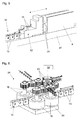
- FIG. 1 shows an arrangement of a forming press 2 in the form of a press brake and a tool changing device 1, which is placed in the immediate vicinity of the forming press 2, in this case in addition to the forming press 2.
- the tool changing device 1 comprises a first tool magazine 3 for storing stamp tools 7 and a second tool magazine 4 for storing counter tools 8 for the stamp tools 7, wherein the two tool magazines 3 and 4 are arranged one above the other in the use position.
- Each of the tool magazines 3 and 4 has a driven, rotatably mounted and in use position horizontally oriented disc 19 and 20 with receiving means 21 for receiving the forming tools 7 and 8, wherein these receiving means 21 are formed such that the forming tools 7 and 8 at a rotation of the disc 19 and 20 are fixed.
- FIG. 1 is the drive device 25 for the first, ie upper tool magazine 3 for storing the stamp tools 7 to see.
- the drive device for the second tool magazine 4 is arranged in the housing of the tool changing device 1 below the second tool magazine 4 for storing the counter tools 8 for the stamp tools 7 and thus not visible.
- the two tool magazines 3 and 4 are height adjustable, so that the altitude of the tool magazines 3 and 4 can be adjusted in a simple manner with respect to the forming press 2.
- the tool changing device 1 comprises a first transfer device 5 for transferring the forming tools 7 storable in the first tool magazine 3 from the first tool magazine 3 to the forming press 2 and in the reverse direction, and a second transfer device 6 for transferring the forming tools 8 storable in the second tool magazine 4 from the second tool magazine 4 Forming press 2 and in the opposite direction.
- the two transmission devices 5 and 6 have a drivable push chain 9 or 10 for the transmission of compressive and tensile forces.
- each of the two push chains 9 and 10 comprises a coupling device 11 or 12 for the temporary coupling of a forming tool 7 and 8 to the push chain 9 and 10, said coupling device 11 and 12 in the illustrated embodiment at a first end of the push chain 9 and 10 is arranged.
- the thrust chains 9 and 10 are, starting from a second end, respectively in a spiral-shaped chain memory 17 and 18, which is arranged in the upper region of the tool changing device 1, storable.
- the tool changing device 1 is connected via two devices 22 and 23 to the forming press 2, wherein the two devices 22 and 23 each have a guide for the push chain 9 and 10 and / or associated elements.
- one of the tool magazines 3 and 4, one of the devices 22 and 23 for connecting the tool changing devices 1 to the forming press 2 and one of the clamping bar 26 and 27 of the press brake 2 is arranged at a same height, so that the transmission of Forming tools 7 and 8 takes place between the tool magazines 3 and 4 and the forming press 2 each in a horizontal plane.
- FIG. 1 also the drive device 24 for the lower push chain 10 is shown schematically. Details of this drive device 24 are in the course of the description of FIG. 6 explained in more detail.
- FIG. 2 shows an enlarged section of the tool changing device.
- This figure shows in particular the two tool magazines 3 and 4 in the form of rotatably mounted discs 19 and 20, on which the stamping tools 7 and the counter tools 8 are arranged for the stamping tools 7.
- the two discs 19 and 20 have groove-shaped receiving means 21 for receiving the forming tools 7 and 8, wherein these receiving means 21 are formed such that the forming tools 7 and 8 are fixed at a rotation of the disc 19 and 20 respectively.
- the discs 19 and 20 of the tool magazines 3 and 4 each have a central recess in this embodiment, the thrust chains 9 and 10 through at least one of the recesses - in this case by the recess of the disc 19 of the first tool magazine. 3 - be guided to the chain memories.
- the push chains are formed of individual chain links 13, wherein the chain links 13 recesses 14 for receiving, preferably electrical, lines 15 have.
- the push chains can thus not only pressure and tensile forces, but - in the case of electrical lines - also transmit electrical signals.
- FIG. 5 shows in an enlarged section the coupling device 12 for the temporary coupling of a forming tool 8 to the end of the push chain 10.
- the coupling takes place via coupling elements 31 in the form of electromagnets.
- the power supply of the electromagnets is ensured via lines 15.
- an electrical storage medium can be provided to ensure the power supply.
- the coupling device 12 also includes a measuring system for determining the position of the coupling device 12, by means of which the position of the coupling device 12 and thus the position of the forming tool 8 coupled to the coupling device 12 can be determined with respect to the forming press or the tool changing device.
- a measuring system can be provided that does not move with the coupling device, but is stationary with respect to the tool changing device or with respect to the forming press and the position of the coupling device or the position of a forming tool coupled to the coupling device detected by, for example, optical means.
- the communication with the measuring system can - as in the case shown - via signal lines that are integrated into the push chain 10, and / or wirelessly, eg by radio, done.
- the push chains are each driven by a drive device, wherein the drive device 24 for the lower push chain 10 schematically in FIG. 6 is shown. It can be seen that the drive device 24 comprises two pairs of drive shafts 16 arranged one behind the other. The power transmission from the drive shafts 16 to the push chain 10 takes place via a frictional engagement, wherein the drive shafts 16 are coated to increase the frictional engagement.
- the contact forces of the drive shafts 16 to the push chain 10 by means of adjusting means comprising springs, adjustable.
- adjusting means comprising springs, adjustable.
- the drive shafts 16 are driven by a motor 32 in the form of a servomotor, wherein between the motor 32 and the drive shafts 16, a gear device with a plurality of gears 33 is provided.
- the drive device 24 further comprises a housing 34.
- Another possibility to drive the push chain is to provide a drive device which comprises drive wheels and / or drive pulleys, which engage positively in the push chain.
Landscapes
- Engineering & Computer Science (AREA)
- Mechanical Engineering (AREA)
- Bending Of Plates, Rods, And Pipes (AREA)
- Mounting, Exchange, And Manufacturing Of Dies (AREA)
Abstract
Werkzeugwechselvorrichtung (1) für eine Umformpresse (2), insbesondere für eine Abkantpresse, mit wenigstens einem Werkzeugmagazin (3, 4) und wenigstens einer Übertragungsvorrichtung (5, 6) zur Übertragung der im wenigstens einen Werkzeugmagazin (3, 4) speicherbaren Umformwerkzeuge (7, 8) vom wenigstens einen Werkzeugmagazin (3, 4) zur Umformpresse (2) und in umgekehrter Richtung, wobei die wenigstens eine Übertragungsvorrichtung (5, 6) eine antreibbare Schubkette (9, 10) zur Übertragung von Druck- und Zugkräften umfasst.Tool changing device (1) for a forming press (2), in particular for a press brake, with at least one tool magazine (3, 4) and at least one transfer device (5, 6) for transferring the forming tools (7) storable in the at least one tool magazine (3, 4) , 8) from the at least one tool magazine (3, 4) to the forming press (2) and in the reverse direction, wherein the at least one transmission device (5, 6) comprises a drivable push chain (9, 10) for transmitting compressive and tensile forces.
Description
Die Erfindung betrifft eine Werkzeugwechselvorrichtung für eine Umformpresse, insbesondere für eine Abkantpresse, mit wenigstens einem Werkzeugmagazin und wenigstens einer Übertragungsvorrichtung zur Übertragung der im wenigstens einen Werkzeugmagazin speicherbaren Umformwerkzeuge vom wenigstens einen Werkzeugmagazin zur Umformpresse und in umgekehrter Richtung. Die Erfindung betrifft weiterhin eine Anordnung aus einer Umformpresse und einer erfindungsgemäßen Werkzeugwechselvorrichtung.The invention relates to a tool changing device for a forming press, in particular for a press brake, with at least one tool magazine and at least one transfer device for transferring the stored in at least one tool magazine forming tools from at least one tool magazine for forming and in the reverse direction. The invention further relates to an arrangement of a forming press and a tool changing device according to the invention.
Umformpressen, wie z. B. Biege- oder Abkantpressen, werden in der Regel mit austauschbaren Werkzeugsätzen betrieben. Je nach Art des herzustellenden Werkstücks bzw. je nach Art des durchzuführenden Biegeschritts an einem Werkstück muss ein bestimmter Werkzeugsatz verwendet werden. Das Umrüsten der Werkzeugsätze erfolgt dabei meistens per Hand. Das ist jedoch nachteilig, da der Umrüstvorgang, insbesondere bei schweren Umformwerkzeugen, körperlich anstrengend ist. Außerdem erfordert er einen hohen Zeitaufwand, wodurch insbesondere die Fertigung kleiner und mittlerer Losgrößen teuer ist.Forming presses, such as. B. bending or press brake, are usually operated with replaceable tool sets. Depending on the type of workpiece to be produced or depending on the type of bending step to be performed on a workpiece, a specific tool set must be used. The conversion of the tool sets is usually done by hand. However, this is disadvantageous because the conversion process, especially in heavy forming tools, is physically demanding. He also requires a lot of time, which in particular the production of small and medium lot sizes is expensive.
Es gibt Ansätze, den Umrüstprozess zu automatisieren. Dabei kommen Robotorarme oder verfahrbare Greifer zum Einsatz, um die Werkzeugsätze auszutauschen.There are approaches to automate the conversion process. Robotic arms or movable grippers are used to exchange the tool sets.
Derartige Lösungen sind allerdings technologisch sehr aufwendig und haben aufgrund des Arbeitsraums, den z.B. ein Roboterarm in Anspruch nimmt, einen hohen Platzbedarf.However, such solutions are technologically very complex and have due to the working space, the e.g. a robot arm takes up a lot of space.
Die Aufgabe der vorliegenden Erfindung besteht darin, die beschriebenen Nachteile unter Angabe einer gegenüber dem Stand der Technik verbesserten Werkzeugwechselvorrichtung bzw. einer Anordnung aus einer Umformpresse und einer solchen Werkzeugwechselvorrichtung zu vermeiden.The object of the present invention is to avoid the disadvantages described by stating a comparison with the prior art improved tool changing device or an arrangement of a forming press and such a tool changing device.
Diese Aufgabe wird durch die Merkmale des unabhängigen Anspruchs 1 gelöst.This object is solved by the features of independent claim 1.
Es ist also erfindungsgemäß vorgesehen, dass die wenigstens eine Übertragungsvorrichtung eine antreibbare Schubkette zur Übertragung von Druck- und Zugkräften umfasst.It is therefore provided according to the invention that the at least one transmission device comprises a drivable push chain for the transmission of compressive and tensile forces.
Durch das Vorsehen einer Schubkette wird eine äußerst zuverlässige und präzise arbeitende Übertragungsvorrichtung realisiert. Außerdem kann die Werkzeugwechselvorrichtung sehr kompakt gebaut werden.By providing a push chain, a highly reliable and precise transmission device is realized. In addition, the tool changing device can be built very compact.
Gemäß einer vorteilhaften Ausgestaltung der Erfindung ist es vorgesehen, dass die Schubkette wenigstens eine Koppelungsvorrichtung zur temporären Koppelung eines Umformwerkzeugs an die Schubkette umfasst. Dabei kann es besonders vorteilhaft sein, wenn ein Messsystem zur, vorzugsweise fortlaufenden, Bestimmung der Position der Koppelungsvorrichtung - und damit zur Bestimmung der Position des mit der Koppelungsvorrichtung gekoppelten Umformwerkzeugs in Bezug auf die Werkzeugwechselvorrichtung bzw. in Bezug auf die Umformpresse -vorgesehen ist. Dabei kann das Messsystem in die Koppelungsvorrichtung integriert sein. Alternativ oder ergänzend dazu kann auch ein Messsystem vorgesehen sein, dass sich nicht mit der Koppelungsvorrichtung mitbewegt, sondern an einem in Bezug auf die Werkzeugwechselvorrichtung bzw. in Bezug auf die Umformpresse positionsfesten Bauteil angeordnet ist und die Position der Koppelungseinheit bzw. eines mit der Koppelungseinheit gekoppelten Umformwerkzeugs z.B. optisch erfasst.According to an advantageous embodiment of the invention, it is provided that the push chain comprises at least one coupling device for the temporary coupling of a forming tool to the push chain. It may be particularly advantageous if a measuring system for, preferably continuously, determining the position of the coupling device - and thus for determining the position of the coupling device coupled to the forming tool with respect to the tool changing device or in relation to the forming press -vorgesehen. In this case, the measuring system can be integrated in the coupling device. Alternatively or additionally, a measuring system may be provided which does not move with the coupling device, but is arranged on a component fixed in position relative to the tool changing device or with respect to the forming press and the position of the coupling unit or one coupled to the coupling unit Forming tool eg optically recorded.
Erfordert die Koppelungsvorrichtung die Versorgung mit elektrischer Energie bzw. die Weiterleitung von Signalen zur bzw. von der Koppelungsvorrichtung, so ist es weiterhin vorteilhaft, wenn die Schubkette aus Kettengliedern gebildet ist, die Ausnehmungen zur Aufnahme von, vorzugsweise elektrischen, Leitungen aufweisen. In diesem Fall überträgt die Schubkette also nicht nur Druck- und Zugkräfte, sondern eben z.B. auch elektrische Energie.If the coupling device requires the supply of electrical energy or the forwarding of signals to and from the coupling device, then it is furthermore advantageous if the push chain is formed from chain links which have recesses for receiving, preferably electrical, lines. In this case, the push chain transmits not only compressive and tensile forces, but also e.g. also electrical energy.
Als günstig hat es sich erwiesen, dass die Schubkette über wenigstens eine Antriebsvorrichtung antreibbar ist, wobei die wenigstens eine Antriebsvorrichtung bevorzugt wenigstens ein Paar, besonders bevorzugt zwei Paare, von Antriebswellen umfasst. Dabei kann es vorgesehen sein, dass die Kraftübertragung von der wenigstens einen Antriebsvorrichtung auf die Schubkette über einen Reibschluss und/oder über einen Formschluss erfolgt. Weiterhin kann es vorgesehen sein, dass die Antriebswellen (zur Erhöhung des Reibschlusses) beschichtet sind, und/oder Anpresskräfte der Antriebswellen an die Schubkette mittels wenigstens einer Einstelleinrichtung, die vorzugsweise wenigstens eine Feder umfasst, verstellbar sind.It has proved to be favorable that the push chain can be driven by at least one drive device, wherein the at least one drive device preferably comprises at least one pair, particularly preferably two pairs, of drive shafts. It may be provided that the power transmission from the at least one drive device to the push chain via a frictional connection and / or via a positive connection. Furthermore, it may be provided that the Drive shafts (to increase the frictional engagement) are coated, and / or contact forces of the drive shafts to the push chain by means of at least one adjusting device, which preferably comprises at least one spring, are adjustable.
Ein weiterer Vorteil der Verwendung einer Schubkette besteht darin, dass sie sich äußerst kompakt speichern lässt. Hierzu ist es gemäß einem vorteilhaften Ausführungsbeispiel der Erfindung vorgesehen, dass die Werkzeugwechselvorrichtung wenigstens einen, vorzugsweisen spiralförmig ausgebildeten, Kettenspeicher zur Speicherung der Schubkette umfasst.Another advantage of using a push chain is that it can be stored extremely compact. For this purpose, it is provided according to an advantageous embodiment of the invention that the tool changing device comprises at least one, preferably spiral-shaped, chain memory for storing the push chain.
Um die Werkzeugwechselvorrichtung flexibel an unterschiedliche Umformpressen anpassen zu können, kann es weiterhin vorgesehen sein, dass das wenigstens eine Werkzeugmagazin höhenverstellbar und/oder seitenverstellbar zur Anpassung der Höhenlage bzw. Seitenlage des wenigstens einen Werkzeugmagazins an die Umformpresse ausgebildet ist.To be able to adapt the tool changing device flexibly to different forming presses, it can furthermore be provided that the at least one tool magazine is designed to be height adjustable and / or laterally adjustable for adapting the vertical position or lateral position of the at least one tool magazine to the forming press.
Als vorteilhaft hat es sich herausgestellt, dass das wenigstens eine Werkzeugmagazin eine antreibbare, drehbar gelagerte, und in Gebrauchslage vorzugsweise horizontal ausgerichtete, Scheibe mit Aufnahmemitteln zur Aufnahme der Umformwerkzeuge umfasst, wobei die Aufnahmemittel besonders bevorzugt derart ausgebildet sind, dass die Umformwerkzeuge bei einer Drehung der Scheibe fixiert sind. Die Fixierung kann dabei z. B. durch eine Verklemmung erfolgen. Um die Speicherkapazität zu erhöhen, können mehrere derartige Scheiben, deren Höhenlagen, vorzugsweise automatisch, verstellbar sind, vorgesehen sein.It has proven to be advantageous that the at least one tool magazine comprises a drivable, rotatably mounted, and in the position of use preferably horizontally aligned, disc with receiving means for receiving the forming tools, wherein the receiving means are particularly preferably designed such that the forming tools in a rotation of the Disc are fixed. The fixation can be z. B. done by jamming. In order to increase the storage capacity, a plurality of such disks, whose altitudes, preferably automatically, are adjustable, can be provided.
Da eine Umformpresse, wie z. B. eine Abkantpresse, zwei verschiedene Arten von Umformwerkzeugen erfordert, nämlich zum einen Stempelwerkzeuge und zum anderen Gegenwerkzeuge für die Stempelwerkzeuge, hat es sich als vorteilhaft erwiesen, dass die Werkzeugwechselvorrichtung wenigstens ein erstes Werkzeugmagazin zur Speicherung der Stempelwerkzeuge und wenigstens ein zweites Werkzeugmagazin zur Speicherung der Gegenwerkzeuge für die Stempelwerkzeuge umfasst, wobei die Werkzeugmagazine in Gebrauchslage vorzugsweise übereinander angeordnet sind.Since a forming press, such. B. a press brake, two different types of forming tools requires, namely a punch tools and other counter tools for stamping tools, it has proved to be advantageous that the tool changing device at least a first tool magazine for storing the stamping tools and at least a second tool magazine for storing the Contains counter tools for stamping tools, the tool magazines are preferably arranged one above the other in the use position.
Diese Ausgestaltung der Erfindung kann in günstiger Weise dadurch weitgebildet werden, dass die Werkzeugwechselvorrichtung eine erste Übertragungsvorrichtung zur Übertragung der im ersten Werkzeugmagazin speicherbaren Umformwerkzeuge vom ersten Werkzeugmagazin zur Umformpresse und in umgekehrter Richtung sowie eine zweite Übertragungsvorrichtung zur Übertragung der im zweiten Werkzeugmagazin speicherbaren Umformwerkzeuge vom zweiten Werkzeugmagazin zur Umformpresse und in umgekehrter Richtung umfasst, wobei vorzugsweise beide Übertragungsvorrichtungen eine antreibbare Schubkette zur Übertragung von Druck- und Zugkräften umfassen. Die Idee hinter dieser Ausgestaltung besteht also darin, dass die Stempelwerkzeuge sowie die Gegenwerkzeuge für die Stempelwerkzeuge gleichzeitig und unabhängig voneinander von dem jeweiligen Werkzeugmagazin zur Umformpresse und in umgekehrter Richtung übertragen werden können. Dadurch lässt sich die für den Umrüstprozess benötigte Zeit weiter reduzieren.This embodiment of the invention can be favorably further developed in that the tool changing device a first transfer device for transferring the storable in the first tool magazine forming tools from the first tool magazine for forming and in the reverse direction and a second transfer device for transferring storable in the second tool magazine forming tools from the second tool magazine to the forming press and in the reverse direction, wherein preferably both transmission devices comprise a drivable push chain for the transmission of compressive and tensile forces. The idea behind this embodiment is therefore that the punch tools and the counter tools for the stamp tools can be transferred simultaneously and independently from the respective tool magazine to the forming press and in the reverse direction. As a result, the time required for the conversion process can be further reduced.
Um ein vollautomatisches Umrüsten in vorteilhafter Weise realisieren zu können, kann es vorgesehen sein, dass ein Steuerungssystem zur Steuerung der Werkzeugwechselvorrichtung, vorzugsweise zur vollautomatischen Übertragung der im wenigstens einen Werkzeugmagazin speicherbaren Umformwerkzeuge vom wenigstens einen Werkzeugmagazin zur Umformpresse und in umgekehrter Richtung gemäß einem vorbestimmten Programm, vorgesehen ist, wobei das Steuerungssystem vorzugsweise wenigstens einen Prozessor und/oder einen Speicher zur Speicherung eines Programms umfasst. Läuft der Umrüstprozess vollautomatisch gemäß einem vorbestimmten Programm ab, so ist es nicht mehr erforderlich, dass sich eine Bedienperson in unmittelbarer Nähe der Werkzeugwechselvorrichtung bzw. der Umformpresse aufhält. Hierdurch lässt sich die Sicherheit für das Bedienpersonal erhöhen.In order to be able to realize a fully automatic conversion in an advantageous manner, it can be provided that a control system for controlling the tool changing device, preferably for fully automatic transfer of the resettable in at least one tool magazine forming tools from at least one tool magazine for forming and in the reverse direction according to a predetermined program, is provided, wherein the control system preferably comprises at least one processor and / or a memory for storing a program. If the changeover process is fully automatic according to a predetermined program, then it is no longer necessary for an operator to be in the immediate vicinity of the tool changing device or the forming press. This can increase the safety of the operator.
Unterstützend kann die Sicherheit dadurch erhöht werden, dass ein Detektionssystem zur Detektion eines sich in der Nähe der Werkzeugwechselvorrichtung befindlichen Objekts, vorzugsweise einer Bedienperson, vorgesehen ist. Auf diese Weise kann sichergestellt werden, dass sich niemand im Gefahrenbereich der Werkzeugwechselvorrichtung bzw. der Umformpresse während des Umrüstvorgangs aufhält. Vorteilhafterweise umfasst das Detektionssystem Lasermittel, wie z. B. Lichtschranken oder dergleichen, die während des Umrüstvorgangs aktiv sind und bei Detektion eines Objekts eine sofortige Unterbrechung des Umrüstvorgangs bewirken. Und schließlich kann es gemäß einem vorteilhaften Ausführungsbeispiel der Erfindung vorgesehen sein, dass die Werkzeugwechselvorrichtung wenigstens eine Vorrichtung zur Anbindung der Werkzeugwechselvorrichtung an die Umformpresse umfasst, wobei diese Vorrichtung vorzugsweise eine Führung für die Schubkette und/oder damit verbundene Elemente aufweist.In support of this, the security can be increased by providing a detection system for detecting an object, preferably an operator, located in the vicinity of the tool changing device. In this way it can be ensured that no one is in the danger zone of the tool changing device or the forming press during the conversion process. Advantageously, the detection system comprises laser means, such as. As photocells or the like, which are active during the conversion process and cause an immediate interruption of the conversion process upon detection of an object. Finally, it can be provided according to an advantageous embodiment of the invention that the tool changing device comprises at least one device for connecting the tool changing device to the forming press, said device preferably has a guide for the push chain and / or associated elements.
Schutz wird auch begehrt für eine Anordnung aus einer Umformpresse und einer erfindungsgemäßen Werkzeugwechselvorrichtung sowie für die Verwendung einer Schubkette zur Übertragung von Druck- und Zugkräften in einer erfindungsgemäßen Werkzeugwechselvorrichtung.Protection is also sought for an arrangement of a forming press and a tool changing device according to the invention and for the use of a push chain for the transmission of compressive and tensile forces in a tool changing device according to the invention.
Weitere Einzelheiten und Vorteile der vorliegenden Erfindung werden anhand der Figurenbeschreibung unter Bezugnahme auf die Zeichnungen im Folgenden näher erläutert. Dabei zeigt:
- Fig. 1
- eine Anordnung aus einer erfindungsgemäßen Werkzeugwechselvorrichtung und einer Umformpresse in Form einer Abkantpresse,
- Fig. 2
- einen Ausschnitt der erfindungsgemäßen Werkzeugwechselvorrichtung,
- Fig. 3
- einen Ausschnitt der Schubkette in einer perspektivischen schematischen Ansicht,
- Fig. 4
- eine Draufsicht auf die Schubkette,
- Fig. 5
- die mit der Schubkette verbundene Koppelungsvorrichtung zur temporären Koppelung eines Umformwerkzeugs an die Schubkette, und
- Fig. 6
- eine Antriebsvorrichtung für die Schubkette.
- Fig. 1
- an arrangement of a tool changing device according to the invention and a forming press in the form of a press brake,
- Fig. 2
- a detail of the tool changing device according to the invention,
- Fig. 3
- a section of the push chain in a perspective schematic view,
- Fig. 4
- a top view of the push chain,
- Fig. 5
- the coupling device connected to the push chain for the temporary coupling of a forming tool to the push chain, and
- Fig. 6
- a drive device for the push chain.
Die Werkzeugwechselvorrichtung 1 umfasst ein erstes Werkzeugmagazin 3 zur Speicherung von Stempelwerkzeugen 7 und ein zweites Werkzeugmagazin 4 zur Speicherung von Gegenwerkzeugen 8 für die Stempelwerkzeuge 7, wobei die beiden Werkzeugmagazine 3 und 4 in Gebrauchslage übereinander angeordnet sind. Jedes der Werkzeugmagazine 3 bzw. 4 weist eine antreibbare, drehbar gelagerte und in Gebrauchlage horizontal ausgerichtete Scheibe 19 bzw. 20 mit Aufnahmemitteln 21 zur Aufnahme der Umformwerkzeuge 7 und 8 auf, wobei diese Aufnahmemittel 21 derart ausgebildet sind, dass die Umformwerkzeuge 7 und 8 bei einer Drehung der Scheibe 19 bzw. 20 fixiert sind.The tool changing device 1 comprises a
In der
Die beiden Werkzeugmagazine 3 und 4 sind höhenverstellbar ausgebildet, sodass die Höhenlage der Werkzeugmagazine 3 und 4 in einfacher Weise in Bezug auf die Umformpresse 2 angepasst werden kann.The two
Die Werkzeugwechselvorrichtung 1 umfasst eine erste Übertragungsvorrichtung 5 zur Übertragung der im ersten Werkzeugmagazin 3 speicherbaren Umformwerkzeuge 7 vom ersten Werkzeugmagazin 3 zur Umformpresse 2 und in umgekehrter Richtung, sowie eine zweite Übertragungsvorrichtung 6 zur Übertragung der im zweiten Werkzeugmagazin 4 speicherbaren Umformwerkzeuge 8 vom zweiten Werkzeugmagazin 4 zur Umformpresse 2 und in umgekehrter Richtung. Die beiden Übertragungsvorrichtungen 5 und 6 weisen eine antreibbare Schubkette 9 bzw. 10 zur Übertragung von Druck- und Zugkräften auf.The tool changing device 1 comprises a
Außerdem umfasst jede der beiden Schubketten 9 und 10 eine Koppelungsvorrichtung 11 bzw. 12 zur temporären Koppelung eines Umformwerkzeuges 7 bzw. 8 an die Schubkette 9 bzw. 10, wobei diese Koppelungsvorrichtung 11 bzw. 12 im dargestellten Ausführungsbeispiel an einem ersten Ende der Schubkette 9 bzw. 10 angeordnet ist.In addition, each of the two
Die Schubketten 9 und 10 sind, ausgehend von einem zweiten Ende, jeweils in einem spiralförmig ausgebildeten Kettenspeicher 17 bzw. 18, der im oberen Bereich der Werkzeugwechselvorrichtung 1 angeordnet ist, speicherbar.The
Bei dem dargestellten Ausführungsbeispiel ist es also vorgesehen, dass zwei unabhängige voneinander arbeitende Schubketten 9 und 10 zur Übertragung einerseits der Stempelwerkzeuge 7 und andererseits der Gegenwerkzeuge 8 für die Stempelwerkzeuge 7 vorgesehen sind. Alternativ ist es auch denkbar, dass nur eine Schubkette vorgesehen ist, wobei der mittlere Teil der Schubkette in einem Puffer zwischengespeichert wird. Auch bei einer derartigen Konfiguration könnten die beiden Enden der Schubkette unabhängig voneinander arbeiten.In the illustrated embodiment, it is thus provided that two independent mutually working
Die Werkzeugwechselvorrichtung 1 ist über zwei Vorrichtungen 22 und 23 an die Umformpresse 2 angebunden, wobei die beiden Vorrichtungen 22 und 23 jeweils eine Führung für die Schubkette 9 bzw. 10 und/oder damit verbundene Elemente aufweisen. Im dargestellten Ausführungsbeispiel ist jeweils eines der Werkzeugmagazine 3 bzw. 4, eine der Vorrichtungen 22 bzw. 23 zur Anbindung der Werkzeugwechselvorrichtungen 1 an die Umformpresse 2 sowie einer der Klemmbalken 26 bzw. 27 der Abkantpresse 2 in einer gleichen Höhe angeordnet, sodass die Übertragung der Umformwerkzeuge 7 bzw. 8 zwischen den Werkzeugmagazinen 3 und 4 und der Umformpresse 2 jeweils in einer horizontalen Ebene erfolgt.The tool changing device 1 is connected via two
In
Anhand der
Aus der
Wie anhand der
Die Koppelungsvorrichtung 12 umfasst auch ein Messsystem zur Bestimmung der Position der Koppelungsvorrichtung 12, über welches die Position der Koppelungsvorrichtung 12 und damit die Position des an die Kopplungsvorrichtung 12 gekoppelten Umformwerkzeugs 8 in Bezug auf die Umformpresse bzw. die Werkzeugwechselvorrichtung bestimmt werden kann. Alternativ oder ergänzend kann ein Messsystem vorgesehen sein, dass sich nicht mit der Koppelungsvorrichtung mitbewegt, sondern in Bezug auf die Werkzeugwechselvorrichtung bzw. in Bezug auf die Umformpresse ortsfest angeordnet ist und die Position der Koppelungsvorrichtung bzw. die Position eines mit der Koppelungsvorrichtung gekoppelten Umformwerkzeugs durch z.B. optische Mittel erfasst. Die Kommunikation mit dem Messsystem kann dabei - wie im dargestellten Fall - über Signalleitungen, die in die Schubkette 10 integriert sind, und/oder drahtlos, z.B. per Funk, erfolgen.The
In dem dargestellten Ausführungsbeispiel werden die Schubketten jeweils über eine Antriebsvorrichtung angetrieben, wobei die Antriebsvorrichtung 24 für die untere Schubkette 10 schematisch in
Darüber hinaus sind die Anpresskräfte der Antriebswellen 16 an die Schubkette 10 mittels Einstelleinrichtungen, die Federn umfassen, verstellbar. Durch die Federbelastung werden konstante Anpresskräfte der Antriebswellen 16 an die Schubkette 10 erzeugt - selbst dann, wenn an den Antreibswellen 16 und/oder an der Schubkette 10 Verschleißerscheinungen auftreten.In addition, the contact forces of the
Angetrieben werden die Antriebswellen 16 von einem Motor 32 in Form eines Servomotors, wobei zwischen dem Motor 32 und den Antriebswellen 16 eine Getriebevorrichtung mit mehreren Zahnrädern 33 vorgesehen ist. Die Antriebsvorrichtung 24 umfasst weiterhin ein Gehäuse 34.The
Eine weitere Möglichkeit, die Schubkette anzutreiben besteht darin, eine Antriebsvorrichtung vorzusehen, welche Antriebsräder und/oder Antriebsscheiben umfasst, die formschlüssig in die Schubkette eingreifen.Another possibility to drive the push chain is to provide a drive device which comprises drive wheels and / or drive pulleys, which engage positively in the push chain.
Claims (17)
Priority Applications (10)
| Application Number | Priority Date | Filing Date | Title |
|---|---|---|---|
| ES14001816.9T ES2582566T3 (en) | 2014-05-23 | 2014-05-23 | Tool change device for a forming press |
| EP14001816.9A EP2946846B1 (en) | 2014-05-23 | 2014-05-23 | Tool changing device for a forming press |
| PL14001816T PL2946846T3 (en) | 2014-05-23 | 2014-05-23 | Tool changing device for a forming press |
| EP15000136.0A EP2946847B1 (en) | 2014-05-23 | 2015-01-19 | Tool changing device for a forming press |
| KR1020167036100A KR102331791B1 (en) | 2014-05-23 | 2015-04-24 | Tool changing device for a forming press |
| CN201580027328.5A CN106660094B (en) | 2014-05-23 | 2015-04-24 | Die change equipment for moulding press |
| JP2017513278A JP6553718B2 (en) | 2014-05-23 | 2015-04-24 | Mold changer for press molding machine |
| KR1020217038224A KR102430935B1 (en) | 2014-05-23 | 2015-04-24 | Tool changing device for a forming press |
| PCT/AT2015/000056 WO2015176083A1 (en) | 2014-05-23 | 2015-04-24 | Tool changing device for a forming press |
| US15/313,132 US10399133B2 (en) | 2014-05-23 | 2015-04-24 | Tool changing device for a forming press |
Applications Claiming Priority (1)
| Application Number | Priority Date | Filing Date | Title |
|---|---|---|---|
| EP14001816.9A EP2946846B1 (en) | 2014-05-23 | 2014-05-23 | Tool changing device for a forming press |
Publications (2)
| Publication Number | Publication Date |
|---|---|
| EP2946846A1 true EP2946846A1 (en) | 2015-11-25 |
| EP2946846B1 EP2946846B1 (en) | 2016-04-06 |
Family
ID=51220371
Family Applications (2)
| Application Number | Title | Priority Date | Filing Date |
|---|---|---|---|
| EP14001816.9A Active EP2946846B1 (en) | 2014-05-23 | 2014-05-23 | Tool changing device for a forming press |
| EP15000136.0A Active EP2946847B1 (en) | 2014-05-23 | 2015-01-19 | Tool changing device for a forming press |
Family Applications After (1)
| Application Number | Title | Priority Date | Filing Date |
|---|---|---|---|
| EP15000136.0A Active EP2946847B1 (en) | 2014-05-23 | 2015-01-19 | Tool changing device for a forming press |
Country Status (8)
| Country | Link |
|---|---|
| US (1) | US10399133B2 (en) |
| EP (2) | EP2946846B1 (en) |
| JP (1) | JP6553718B2 (en) |
| KR (2) | KR102430935B1 (en) |
| CN (1) | CN106660094B (en) |
| ES (1) | ES2582566T3 (en) |
| PL (1) | PL2946846T3 (en) |
| WO (1) | WO2015176083A1 (en) |
Cited By (10)
| Publication number | Priority date | Publication date | Assignee | Title |
|---|---|---|---|---|
| WO2016109862A1 (en) * | 2015-01-08 | 2016-07-14 | Trumpf Maschinen Austria Gmbh & Co. Kg. | Feeding device for a bending press |
| WO2017004649A1 (en) * | 2015-07-08 | 2017-01-12 | Trumpf Maschinen Austria Gmbh & Co. Kg. | Bending-tool store |
| WO2017139823A1 (en) * | 2016-02-17 | 2017-08-24 | Trumpf Maschinen Austria Gmbh & Co. Kg. | Press brake |
| WO2017139819A1 (en) * | 2016-02-17 | 2017-08-24 | Trumpf Maschinen Austria Gmbh & Co. Kg. | Press brake and method for changing bending tools of a press brake |
| AT518255A4 (en) * | 2016-02-17 | 2017-09-15 | Trumpf Maschinen Austria Gmbh & Co Kg | Tool change device for a press brake and method for performing a tool change |
| AT519095B1 (en) * | 2016-10-20 | 2018-04-15 | Trumpf Maschinen Austria Gmbh & Co Kg | Feeding method for a machine tool |
| EP3354363A1 (en) * | 2017-01-31 | 2018-08-01 | TRUMPF Maschinen Austria GmbH & Co. KG. | Bending tool storage device |
| WO2018145137A1 (en) * | 2017-02-08 | 2018-08-16 | Trumpf Maschinen Austria Gmbh & Co. Kg. | Bending tool storage device and method for feeding a press brake |
| IT201700088418A1 (en) * | 2017-08-01 | 2019-02-01 | Hydromec S R L | GIOSTRA MULTI-POSITION FOR TOOL CHANGE AND MOLD OF A PRESS |
| EP3808468A4 (en) * | 2018-06-12 | 2021-08-04 | Amada Co., Ltd. | Split die attachment method and press brake |
Families Citing this family (13)
| Publication number | Priority date | Publication date | Assignee | Title |
|---|---|---|---|---|
| CA3168412A1 (en) | 2016-08-26 | 2018-03-01 | Structured I, Llc | Method of producing absorbent structures with high wet strength, absorbancy, and softness |
| CA3034636A1 (en) | 2016-09-09 | 2018-03-15 | Mate Precision Tooling, Inc. | Press brake tool engagement system |
| US10792716B2 (en) * | 2017-06-29 | 2020-10-06 | Mate Precision Tooling, Inc. | Magnetic press brake and machine tooling engagement systems |
| US10953453B2 (en) | 2017-11-06 | 2021-03-23 | Mate Precision Technologies Inc. | Magnetic press brake tooling engagement system |
| CN108526241A (en) * | 2018-04-17 | 2018-09-14 | 山东舜世高科实业有限公司 | A kind of semitrailer guardrail Rollforming Shaped Tube technique and die-changing apparatus |
| CN108687161A (en) * | 2018-04-17 | 2018-10-23 | 山东舜世高科实业有限公司 | A kind of splitting Oil cylinder shape tube moulding process and die-changing apparatus |
| CN108673058B (en) * | 2018-04-17 | 2019-11-19 | 山东舜世高科实业有限公司 | Automobile buffer beam straight seam welding Rollforming Shaped Tube technique and die-changing apparatus |
| AT521489B1 (en) * | 2018-12-13 | 2020-02-15 | Trumpf Maschinen Austria Gmbh & Co Kg | Tool transfer device |
| CN109396385B (en) * | 2018-12-14 | 2020-11-17 | 佛山市南海镕信金属制品有限公司 | Die warehouse of die casting machine |
| CN109732366A (en) * | 2019-01-29 | 2019-05-10 | 东莞市台川数控科技有限公司 | A kind of TCV1170 rapid processing lathe |
| JP7209597B2 (en) * | 2019-07-18 | 2023-01-20 | 株式会社マキタ | electric work machine |
| IT202100026249A1 (en) * | 2021-10-13 | 2023-04-13 | Realmeccanica S R L | MOLD FOR THE COMPACTION OF POWDERS FOR THE MANUFACTURE OF CERAMIC PRODUCTS |
| JP7303347B1 (en) | 2022-04-04 | 2023-07-04 | 株式会社アマダ | Mold storage device and bending system |
Citations (4)
| Publication number | Priority date | Publication date | Assignee | Title |
|---|---|---|---|---|
| EP0377865A2 (en) * | 1989-01-11 | 1990-07-18 | Giancarlo Piccini | Punching and nibbling machine fitted with a device for an automatic quick tool change |
| DE29705509U1 (en) * | 1997-03-27 | 1997-05-15 | Hlawatsch Josef | Transport system for tools |
| DE19643163A1 (en) * | 1996-10-18 | 1998-04-23 | Amada Gmbh | Tool changing device for a forming press and forming press tool changing device arrangement |
| US5791852A (en) * | 1990-06-15 | 1998-08-11 | Federal Business Development Bank | Storage system for automatically storing and removing dies |
Family Cites Families (26)
| Publication number | Priority date | Publication date | Assignee | Title |
|---|---|---|---|---|
| JPS57181725A (en) * | 1981-04-28 | 1982-11-09 | Amada Co Ltd | Automatic metallic mold replacing device of press brake |
| JPS5853334A (en) * | 1981-09-24 | 1983-03-29 | Kobayashi Sharyo Seisakusho:Kk | Metallic die shifting device of press machine |
| JPS58119926U (en) * | 1982-02-04 | 1983-08-16 | 相生精機株式会社 | Mold changing device for processing machines that use molds |
| JPS6257717A (en) | 1985-09-06 | 1987-03-13 | Mitsubishi Electric Corp | Automatic metal die changing device for pess brake |
| JPH0722782B2 (en) * | 1986-04-08 | 1995-03-15 | 株式会社アマダ | Mold management device for turret punch press |
| DE3731871A1 (en) * | 1987-09-18 | 1989-04-06 | Bellheimer Metallwerk Gmbh | CIRCULAR SHELF |
| JPH0527219Y2 (en) * | 1988-02-02 | 1993-07-12 | ||
| JPH0522341Y2 (en) * | 1988-07-20 | 1993-06-08 | ||
| JPH04158926A (en) | 1990-10-24 | 1992-06-02 | Amada Metrecs Co Ltd | Die-set system die for bending and device for automatically changing die using its die |
| US5366431A (en) | 1990-12-13 | 1994-11-22 | Uniflo Conveyor, Inc. | Automated press brake die transfer system |
| JP2544248Y2 (en) * | 1990-12-14 | 1997-08-13 | エスアールエンジニアリング株式会社 | At least a device for pushing and pulling jigs and tools |
| JPH0584414U (en) * | 1992-04-13 | 1993-11-16 | 株式会社アマダ | Automatic mold changer for bending machine |
| US5443166A (en) * | 1993-11-09 | 1995-08-22 | Schutte; John H. | Storage rack for use with a break press |
| JP3204165B2 (en) | 1997-06-16 | 2001-09-04 | 村田機械株式会社 | Punch press machine |
| AUPQ022199A0 (en) * | 1999-05-05 | 1999-06-03 | Lazer Safe Pty Ltd | Industrial press safety system |
| EP1138413A3 (en) | 2000-03-29 | 2002-09-11 | Murata Kikai Kabushiki Kaisha | Press with automatic tool changing function and tool cartridge changing device |
| JP4674885B2 (en) * | 2001-06-04 | 2011-04-20 | 株式会社アマダ | Bending apparatus and method |
| JP5008019B2 (en) * | 2006-09-30 | 2012-08-22 | 株式会社アマダ | Bending machine |
| PL2198991T3 (en) | 2008-12-22 | 2011-12-30 | Trumpf Werkzeugmaschinen Gmbh Co Kg | Sheet metal loading and unloading unit with a tool holder for sheet metal processing machines |
| AT509708B1 (en) | 2010-09-02 | 2011-11-15 | Trumpf Maschinen Austria Gmbh | TOOL MAGAZINE FOR A MANIPULATOR |
| AT510409B1 (en) * | 2011-02-01 | 2012-04-15 | Trumpf Maschinen Austria Gmbh & Co Kg | MANUFACTURING DEVICE WITH TOOL POSITION DETECTION MEANS AND METHOD OF OPERATING THEREOF |
| DE102014116386A1 (en) * | 2014-11-10 | 2016-05-12 | Trumpf Maschinen Austria Gmbh & Co.Kg. | Bending press and feeding device for a bending press |
| AT516043B1 (en) * | 2014-11-12 | 2016-02-15 | Trumpf Maschinen Austria Gmbh | Bending press and feeding device for a bending press |
| AT516690B1 (en) * | 2015-01-08 | 2016-12-15 | Trumpf Maschinen Austria Gmbh & Co Kg | Feeding device for a bending press |
| AT517387B1 (en) * | 2015-07-08 | 2017-03-15 | Trumpf Maschinen Austria Gmbh & Co Kg | Bending tool storage device |
| JP2017032771A (en) * | 2015-07-31 | 2017-02-09 | ブラザー工業株式会社 | Image formation device, program, and method for controlling image formation device |
-
2014
- 2014-05-23 ES ES14001816.9T patent/ES2582566T3/en active Active
- 2014-05-23 PL PL14001816T patent/PL2946846T3/en unknown
- 2014-05-23 EP EP14001816.9A patent/EP2946846B1/en active Active
-
2015
- 2015-01-19 EP EP15000136.0A patent/EP2946847B1/en active Active
- 2015-04-24 CN CN201580027328.5A patent/CN106660094B/en active Active
- 2015-04-24 KR KR1020217038224A patent/KR102430935B1/en active IP Right Grant
- 2015-04-24 US US15/313,132 patent/US10399133B2/en active Active
- 2015-04-24 WO PCT/AT2015/000056 patent/WO2015176083A1/en active Application Filing
- 2015-04-24 KR KR1020167036100A patent/KR102331791B1/en active IP Right Grant
- 2015-04-24 JP JP2017513278A patent/JP6553718B2/en active Active
Patent Citations (4)
| Publication number | Priority date | Publication date | Assignee | Title |
|---|---|---|---|---|
| EP0377865A2 (en) * | 1989-01-11 | 1990-07-18 | Giancarlo Piccini | Punching and nibbling machine fitted with a device for an automatic quick tool change |
| US5791852A (en) * | 1990-06-15 | 1998-08-11 | Federal Business Development Bank | Storage system for automatically storing and removing dies |
| DE19643163A1 (en) * | 1996-10-18 | 1998-04-23 | Amada Gmbh | Tool changing device for a forming press and forming press tool changing device arrangement |
| DE29705509U1 (en) * | 1997-03-27 | 1997-05-15 | Hlawatsch Josef | Transport system for tools |
Cited By (28)
| Publication number | Priority date | Publication date | Assignee | Title |
|---|---|---|---|---|
| WO2016109862A1 (en) * | 2015-01-08 | 2016-07-14 | Trumpf Maschinen Austria Gmbh & Co. Kg. | Feeding device for a bending press |
| WO2017004649A1 (en) * | 2015-07-08 | 2017-01-12 | Trumpf Maschinen Austria Gmbh & Co. Kg. | Bending-tool store |
| AT517353A4 (en) * | 2015-07-08 | 2017-01-15 | Trumpf Maschinen Austria Gmbh & Co Kg | Bending tool storage |
| AT517353B1 (en) * | 2015-07-08 | 2017-01-15 | Trumpf Maschinen Austria Gmbh & Co Kg | Bending tool storage |
| WO2017139823A1 (en) * | 2016-02-17 | 2017-08-24 | Trumpf Maschinen Austria Gmbh & Co. Kg. | Press brake |
| WO2017139819A1 (en) * | 2016-02-17 | 2017-08-24 | Trumpf Maschinen Austria Gmbh & Co. Kg. | Press brake and method for changing bending tools of a press brake |
| AT518255A4 (en) * | 2016-02-17 | 2017-09-15 | Trumpf Maschinen Austria Gmbh & Co Kg | Tool change device for a press brake and method for performing a tool change |
| AT518255B1 (en) * | 2016-02-17 | 2017-09-15 | Trumpf Maschinen Austria Gmbh & Co Kg | Tool change device for a press brake and method for performing a tool change |
| CN109922921B (en) * | 2016-10-20 | 2021-02-19 | 特鲁普机械奥地利有限公司及两合公司 | Loading method for machine tool and tool transfer device |
| AT519095B1 (en) * | 2016-10-20 | 2018-04-15 | Trumpf Maschinen Austria Gmbh & Co Kg | Feeding method for a machine tool |
| WO2018071945A1 (en) * | 2016-10-20 | 2018-04-26 | Trumpf Maschinen Austria Gmbh & Co. Kg. | Loading method for a machine tool and tool transfer device |
| WO2018071946A3 (en) * | 2016-10-20 | 2018-07-05 | Trumpf Maschinen Austria Gmbh & Co. Kg. | Device for positioning a bending tool |
| US11491530B2 (en) | 2016-10-20 | 2022-11-08 | Trumpf Maschinen Austria Gmbh & Co. Kg | Device for positioning a bending tool |
| US11471927B2 (en) | 2016-10-20 | 2022-10-18 | Trumpf Maschinen Austria Gmbh & Co. Kg | Loading method for a machine tool and tool transfer device |
| EP3943235A1 (en) * | 2016-10-20 | 2022-01-26 | TRUMPF Maschinen Austria GmbH & Co. KG. | Loading method for a machine tool and tool transfer device |
| CN112935116A (en) * | 2016-10-20 | 2021-06-11 | 特鲁普机械奥地利有限公司及两合公司 | Loading method for machine tool and tool transfer device |
| CN109922900A (en) * | 2016-10-20 | 2019-06-21 | 特鲁普机械奥地利有限公司及两合公司 | Position the device of flector |
| CN109922921A (en) * | 2016-10-20 | 2019-06-21 | 特鲁普机械奥地利有限公司及两合公司 | The stowage and tool delivery device of lathe |
| AT522347A5 (en) * | 2016-10-20 | 2020-10-15 | Trumpf Maschinen Austria Gmbh & Co Kg | Device for positioning a bending tool |
| AT522347B1 (en) * | 2016-10-20 | 2020-11-15 | Trumpf Maschinen Austria Gmbh & Co Kg | Device for positioning a bending tool |
| CN109922900B (en) * | 2016-10-20 | 2020-11-20 | 特鲁普机械奥地利有限公司及两合公司 | Method for positioning a bending tool |
| AT519095A4 (en) * | 2016-10-20 | 2018-04-15 | Trumpf Maschinen Austria Gmbh & Co Kg | Feeding method for a machine tool |
| EP3354363A1 (en) * | 2017-01-31 | 2018-08-01 | TRUMPF Maschinen Austria GmbH & Co. KG. | Bending tool storage device |
| WO2018145137A1 (en) * | 2017-02-08 | 2018-08-16 | Trumpf Maschinen Austria Gmbh & Co. Kg. | Bending tool storage device and method for feeding a press brake |
| EP3437752A1 (en) * | 2017-08-01 | 2019-02-06 | Hydromec S.r.l. | Multistation carousel for changing a tool and die of a press |
| IT201700088418A1 (en) * | 2017-08-01 | 2019-02-01 | Hydromec S R L | GIOSTRA MULTI-POSITION FOR TOOL CHANGE AND MOLD OF A PRESS |
| EP3808468A4 (en) * | 2018-06-12 | 2021-08-04 | Amada Co., Ltd. | Split die attachment method and press brake |
| US11794231B2 (en) | 2018-06-12 | 2023-10-24 | Amada Co., Ltd. | Divided tool attachment method and press brake |
Also Published As
| Publication number | Publication date |
|---|---|
| KR20170013312A (en) | 2017-02-06 |
| ES2582566T3 (en) | 2016-09-13 |
| WO2015176083A1 (en) | 2015-11-26 |
| EP2946847B1 (en) | 2021-12-08 |
| JP6553718B2 (en) | 2019-07-31 |
| KR102331791B1 (en) | 2021-11-29 |
| EP2946846B1 (en) | 2016-04-06 |
| US20170144206A1 (en) | 2017-05-25 |
| CN106660094B (en) | 2019-03-01 |
| CN106660094A (en) | 2017-05-10 |
| JP2017516664A (en) | 2017-06-22 |
| KR102430935B1 (en) | 2022-08-08 |
| US10399133B2 (en) | 2019-09-03 |
| EP2946847A1 (en) | 2015-11-25 |
| KR20210145322A (en) | 2021-12-01 |
| PL2946846T3 (en) | 2018-02-28 |
Similar Documents
| Publication | Publication Date | Title |
|---|---|---|
| EP2946846B1 (en) | Tool changing device for a forming press | |
| EP3074152B1 (en) | Tool set-up system for a brake press | |
| EP3027332B1 (en) | Bending tool system | |
| EP3165487A1 (en) | Conduit transportation device, in particular for cables to be processed in cable processing machines | |
| EP3033187A1 (en) | Transfer device for a workpiece | |
| EP3448597B1 (en) | Transport method for transferring workpieces | |
| EP1731237B1 (en) | Metal sheet working machine | |
| AT512775B1 (en) | Production plant for producing an assembly of several components | |
| EP2998107B1 (en) | Press drive for a forming device | |
| EP2029461B1 (en) | Transport installation for parts carriers | |
| EP3372319A2 (en) | Safety system for a production system and such a production sytem | |
| EP3906123A1 (en) | Method for changing the calibration range of a drawing chain, comprising chain links, of a caterpillar-track drawing machine, and caterpillar-track drawing machine | |
| DE102015005487A1 (en) | Machining plant for a workpiece | |
| DE112015004660T5 (en) | pressing device | |
| EP3181254B1 (en) | Manufacturing plant with a tool manipulation unit | |
| CH617108A5 (en) | ||
| EP3141122A1 (en) | Device for laterally charging a strip of dough or piece of dough | |
| DE4221687C2 (en) | Feed device for intermittent feed of strip or wire material | |
| WO2016062399A1 (en) | Device for positioning a thread in a workpiece | |
| EP0344741A2 (en) | Advancing device for feeding sheet metal to a stamping tool | |
| EP2241424A1 (en) | Wood hacker | |
| DE2552678A1 (en) | TRANSFER GROUP FOR THE MECHANICAL CONTROL OF MACHINERY | |
| DE1800978A1 (en) | Device for feeding broadband to stamping presses and the like. | |
| EP2910351A1 (en) | Device for the rotary processing of processed material | |
| DE3703700A1 (en) | Stamping press tool unit |
Legal Events
| Date | Code | Title | Description |
|---|---|---|---|
| 17P | Request for examination filed |
Effective date: 20141022 |
|
| AK | Designated contracting states |
Kind code of ref document: A1 Designated state(s): AL AT BE BG CH CY CZ DE DK EE ES FI FR GB GR HR HU IE IS IT LI LT LU LV MC MK MT NL NO PL PT RO RS SE SI SK SM TR |
|
| AX | Request for extension of the european patent |
Extension state: BA ME |
|
| PUAI | Public reference made under article 153(3) epc to a published international application that has entered the european phase |
Free format text: ORIGINAL CODE: 0009012 |
|
| GRAP | Despatch of communication of intention to grant a patent |
Free format text: ORIGINAL CODE: EPIDOSNIGR1 |
|
| INTG | Intention to grant announced |
Effective date: 20151211 |
|
| GRAS | Grant fee paid |
Free format text: ORIGINAL CODE: EPIDOSNIGR3 |
|
| GRAA | (expected) grant |
Free format text: ORIGINAL CODE: 0009210 |
|
| AK | Designated contracting states |
Kind code of ref document: B1 Designated state(s): AL AT BE BG CH CY CZ DE DK EE ES FI FR GB GR HR HU IE IS IT LI LT LU LV MC MK MT NL NO PL PT RO RS SE SI SK SM TR |
|
| AX | Request for extension of the european patent |
Extension state: BA ME |
|
| REG | Reference to a national code |
Ref country code: GB Ref legal event code: FG4D Free format text: NOT ENGLISH |
|
| REG | Reference to a national code |
Ref country code: AT Ref legal event code: REF Ref document number: 787176 Country of ref document: AT Kind code of ref document: T Effective date: 20160415 Ref country code: CH Ref legal event code: EP |
|
| REG | Reference to a national code |
Ref country code: IE Ref legal event code: FG4D Free format text: LANGUAGE OF EP DOCUMENT: GERMAN |
|
| REG | Reference to a national code |
Ref country code: DE Ref legal event code: R096 Ref document number: 502014000542 Country of ref document: DE |
|
| REG | Reference to a national code |
Ref country code: FR Ref legal event code: PLFP Year of fee payment: 3 |
|
| REG | Reference to a national code |
Ref country code: NL Ref legal event code: FP |
|
| REG | Reference to a national code |
Ref country code: CH Ref legal event code: NV Representative=s name: ABP PATENT NETWORK AG, CH Ref country code: CH Ref legal event code: PUE Owner name: TRUMPF MASCHINEN AUSTRIA GMBH AND CO. KG., AT Free format text: FORMER OWNER: FELDER KG, AT |
|
| REG | Reference to a national code |
Ref country code: SE Ref legal event code: TRGR |
|
| RAP2 | Party data changed (patent owner data changed or rights of a patent transferred) |
Owner name: TRUMPF MASCHINEN AUSTRIA GMBH & CO. KG. |
|
| REG | Reference to a national code |
Ref country code: LT Ref legal event code: MG4D |
|
| REG | Reference to a national code |
Ref country code: ES Ref legal event code: FG2A Ref document number: 2582566 Country of ref document: ES Kind code of ref document: T3 Effective date: 20160913 |
|
| PG25 | Lapsed in a contracting state [announced via postgrant information from national office to epo] |
Ref country code: LT Free format text: LAPSE BECAUSE OF FAILURE TO SUBMIT A TRANSLATION OF THE DESCRIPTION OR TO PAY THE FEE WITHIN THE PRESCRIBED TIME-LIMIT Effective date: 20160406 Ref country code: IS Free format text: LAPSE BECAUSE OF FAILURE TO SUBMIT A TRANSLATION OF THE DESCRIPTION OR TO PAY THE FEE WITHIN THE PRESCRIBED TIME-LIMIT Effective date: 20160806 Ref country code: NO Free format text: LAPSE BECAUSE OF FAILURE TO SUBMIT A TRANSLATION OF THE DESCRIPTION OR TO PAY THE FEE WITHIN THE PRESCRIBED TIME-LIMIT Effective date: 20160706 |
|
| PG25 | Lapsed in a contracting state [announced via postgrant information from national office to epo] |
Ref country code: LV Free format text: LAPSE BECAUSE OF FAILURE TO SUBMIT A TRANSLATION OF THE DESCRIPTION OR TO PAY THE FEE WITHIN THE PRESCRIBED TIME-LIMIT Effective date: 20160406 Ref country code: RS Free format text: LAPSE BECAUSE OF FAILURE TO SUBMIT A TRANSLATION OF THE DESCRIPTION OR TO PAY THE FEE WITHIN THE PRESCRIBED TIME-LIMIT Effective date: 20160406 Ref country code: PT Free format text: LAPSE BECAUSE OF FAILURE TO SUBMIT A TRANSLATION OF THE DESCRIPTION OR TO PAY THE FEE WITHIN THE PRESCRIBED TIME-LIMIT Effective date: 20160808 Ref country code: GR Free format text: LAPSE BECAUSE OF FAILURE TO SUBMIT A TRANSLATION OF THE DESCRIPTION OR TO PAY THE FEE WITHIN THE PRESCRIBED TIME-LIMIT Effective date: 20160707 Ref country code: HR Free format text: LAPSE BECAUSE OF FAILURE TO SUBMIT A TRANSLATION OF THE DESCRIPTION OR TO PAY THE FEE WITHIN THE PRESCRIBED TIME-LIMIT Effective date: 20160406 |
|
| REG | Reference to a national code |
Ref country code: GB Ref legal event code: 732E Free format text: REGISTERED BETWEEN 20161201 AND 20161207 |
|
| PG25 | Lapsed in a contracting state [announced via postgrant information from national office to epo] |
Ref country code: IT Free format text: LAPSE BECAUSE OF FAILURE TO SUBMIT A TRANSLATION OF THE DESCRIPTION OR TO PAY THE FEE WITHIN THE PRESCRIBED TIME-LIMIT Effective date: 20160406 |
|
| REG | Reference to a national code |
Ref country code: DE Ref legal event code: R097 Ref document number: 502014000542 Country of ref document: DE |
|
| REG | Reference to a national code |
Ref country code: DE Ref legal event code: R082 Ref document number: 502014000542 Country of ref document: DE Representative=s name: ANWAELTE BURGER UND PARTNER RECHTSANWALTSKANZL, AT Ref country code: DE Ref legal event code: R081 Ref document number: 502014000542 Country of ref document: DE Owner name: TRUMPF MASCHINEN AUSTRIA GMBH & CO.KG., AT Free format text: FORMER OWNER: FELDER KG, HALL IN TIROL, AT Ref country code: DE Ref legal event code: R082 Ref document number: 502014000542 Country of ref document: DE Representative=s name: ABP BURGER RECHTSANWALTSGESELLSCHAFT MBH, DE |
|
| PG25 | Lapsed in a contracting state [announced via postgrant information from national office to epo] |
Ref country code: MC Free format text: LAPSE BECAUSE OF FAILURE TO SUBMIT A TRANSLATION OF THE DESCRIPTION OR TO PAY THE FEE WITHIN THE PRESCRIBED TIME-LIMIT Effective date: 20160406 Ref country code: DK Free format text: LAPSE BECAUSE OF FAILURE TO SUBMIT A TRANSLATION OF THE DESCRIPTION OR TO PAY THE FEE WITHIN THE PRESCRIBED TIME-LIMIT Effective date: 20160406 Ref country code: EE Free format text: LAPSE BECAUSE OF FAILURE TO SUBMIT A TRANSLATION OF THE DESCRIPTION OR TO PAY THE FEE WITHIN THE PRESCRIBED TIME-LIMIT Effective date: 20160406 Ref country code: RO Free format text: LAPSE BECAUSE OF FAILURE TO SUBMIT A TRANSLATION OF THE DESCRIPTION OR TO PAY THE FEE WITHIN THE PRESCRIBED TIME-LIMIT Effective date: 20160406 |
|
| PLBE | No opposition filed within time limit |
Free format text: ORIGINAL CODE: 0009261 |
|
| STAA | Information on the status of an ep patent application or granted ep patent |
Free format text: STATUS: NO OPPOSITION FILED WITHIN TIME LIMIT |
|
| REG | Reference to a national code |
Ref country code: IE Ref legal event code: MM4A |
|
| PG25 | Lapsed in a contracting state [announced via postgrant information from national office to epo] |
Ref country code: SM Free format text: LAPSE BECAUSE OF FAILURE TO SUBMIT A TRANSLATION OF THE DESCRIPTION OR TO PAY THE FEE WITHIN THE PRESCRIBED TIME-LIMIT Effective date: 20160406 |
|
| 26N | No opposition filed |
Effective date: 20170110 |
|
| REG | Reference to a national code |
Ref country code: SK Ref legal event code: T3 Ref document number: E 22519 Country of ref document: SK |
|
| REG | Reference to a national code |
Ref country code: FR Ref legal event code: PLFP Year of fee payment: 4 |
|
| PG25 | Lapsed in a contracting state [announced via postgrant information from national office to epo] |
Ref country code: SI Free format text: LAPSE BECAUSE OF FAILURE TO SUBMIT A TRANSLATION OF THE DESCRIPTION OR TO PAY THE FEE WITHIN THE PRESCRIBED TIME-LIMIT Effective date: 20160406 Ref country code: IE Free format text: LAPSE BECAUSE OF NON-PAYMENT OF DUE FEES Effective date: 20160523 |
|
| REG | Reference to a national code |
Ref country code: FR Ref legal event code: PLFP Year of fee payment: 5 |
|
| PG25 | Lapsed in a contracting state [announced via postgrant information from national office to epo] |
Ref country code: HU Free format text: LAPSE BECAUSE OF FAILURE TO SUBMIT A TRANSLATION OF THE DESCRIPTION OR TO PAY THE FEE WITHIN THE PRESCRIBED TIME-LIMIT; INVALID AB INITIO Effective date: 20140523 |
|
| PG25 | Lapsed in a contracting state [announced via postgrant information from national office to epo] |
Ref country code: CY Free format text: LAPSE BECAUSE OF FAILURE TO SUBMIT A TRANSLATION OF THE DESCRIPTION OR TO PAY THE FEE WITHIN THE PRESCRIBED TIME-LIMIT Effective date: 20160406 Ref country code: MT Free format text: LAPSE BECAUSE OF FAILURE TO SUBMIT A TRANSLATION OF THE DESCRIPTION OR TO PAY THE FEE WITHIN THE PRESCRIBED TIME-LIMIT Effective date: 20160406 Ref country code: LU Free format text: LAPSE BECAUSE OF NON-PAYMENT OF DUE FEES Effective date: 20160523 Ref country code: MK Free format text: LAPSE BECAUSE OF FAILURE TO SUBMIT A TRANSLATION OF THE DESCRIPTION OR TO PAY THE FEE WITHIN THE PRESCRIBED TIME-LIMIT Effective date: 20160406 |
|
| REG | Reference to a national code |
Ref country code: DE Ref legal event code: R082 Ref document number: 502014000542 Country of ref document: DE Representative=s name: ABP BURGER RECHTSANWALTSGESELLSCHAFT MBH, DE |
|
| PG25 | Lapsed in a contracting state [announced via postgrant information from national office to epo] |
Ref country code: BG Free format text: LAPSE BECAUSE OF FAILURE TO SUBMIT A TRANSLATION OF THE DESCRIPTION OR TO PAY THE FEE WITHIN THE PRESCRIBED TIME-LIMIT Effective date: 20160406 |
|
| PG25 | Lapsed in a contracting state [announced via postgrant information from national office to epo] |
Ref country code: AL Free format text: LAPSE BECAUSE OF FAILURE TO SUBMIT A TRANSLATION OF THE DESCRIPTION OR TO PAY THE FEE WITHIN THE PRESCRIBED TIME-LIMIT Effective date: 20160406 |
|
| PGFP | Annual fee paid to national office [announced via postgrant information from national office to epo] |
Ref country code: TR Payment date: 20190321 Year of fee payment: 6 Ref country code: SE Payment date: 20190326 Year of fee payment: 6 |
|
| PGFP | Annual fee paid to national office [announced via postgrant information from national office to epo] |
Ref country code: SK Payment date: 20190312 Year of fee payment: 6 |
|
| PGFP | Annual fee paid to national office [announced via postgrant information from national office to epo] |
Ref country code: NO Payment date: 20190424 Year of fee payment: 10 Ref country code: PL Payment date: 20190416 Year of fee payment: 6 Ref country code: ES Payment date: 20190604 Year of fee payment: 6 |
|
| PGFP | Annual fee paid to national office [announced via postgrant information from national office to epo] |
Ref country code: GB Payment date: 20190412 Year of fee payment: 6 |
|
| PGFP | Annual fee paid to national office [announced via postgrant information from national office to epo] |
Ref country code: NL Payment date: 20200417 Year of fee payment: 7 |
|
| REG | Reference to a national code |
Ref country code: AT Ref legal event code: MM01 Ref document number: 787176 Country of ref document: AT Kind code of ref document: T Effective date: 20190523 |
|
| PG25 | Lapsed in a contracting state [announced via postgrant information from national office to epo] |
Ref country code: AT Free format text: LAPSE BECAUSE OF NON-PAYMENT OF DUE FEES Effective date: 20190523 |
|
| REG | Reference to a national code |
Ref country code: FI Ref legal event code: MAE |
|
| REG | Reference to a national code |
Ref country code: SK Ref legal event code: MM4A Ref document number: E 22519 Country of ref document: SK Effective date: 20200523 |
|
| PG25 | Lapsed in a contracting state [announced via postgrant information from national office to epo] |
Ref country code: FI Free format text: LAPSE BECAUSE OF NON-PAYMENT OF DUE FEES Effective date: 20200523 Ref country code: SE Free format text: LAPSE BECAUSE OF NON-PAYMENT OF DUE FEES Effective date: 20200524 |
|
| PG25 | Lapsed in a contracting state [announced via postgrant information from national office to epo] |
Ref country code: SK Free format text: LAPSE BECAUSE OF NON-PAYMENT OF DUE FEES Effective date: 20200523 |
|
| REG | Reference to a national code |
Ref country code: BE Ref legal event code: MM Effective date: 20200531 |
|
| GBPC | Gb: european patent ceased through non-payment of renewal fee |
Effective date: 20200523 |
|
| PG25 | Lapsed in a contracting state [announced via postgrant information from national office to epo] |
Ref country code: GB Free format text: LAPSE BECAUSE OF NON-PAYMENT OF DUE FEES Effective date: 20200523 |
|
| PG25 | Lapsed in a contracting state [announced via postgrant information from national office to epo] |
Ref country code: BE Free format text: LAPSE BECAUSE OF NON-PAYMENT OF DUE FEES Effective date: 20200531 |
|
| REG | Reference to a national code |
Ref country code: ES Ref legal event code: FD2A Effective date: 20211001 |
|
| PG25 | Lapsed in a contracting state [announced via postgrant information from national office to epo] |
Ref country code: ES Free format text: LAPSE BECAUSE OF NON-PAYMENT OF DUE FEES Effective date: 20200524 |
|
| REG | Reference to a national code |
Ref country code: NL Ref legal event code: MM Effective date: 20210601 |
|
| PG25 | Lapsed in a contracting state [announced via postgrant information from national office to epo] |
Ref country code: NL Free format text: LAPSE BECAUSE OF NON-PAYMENT OF DUE FEES Effective date: 20210601 |
|
| PG25 | Lapsed in a contracting state [announced via postgrant information from national office to epo] |
Ref country code: TR Free format text: LAPSE BECAUSE OF NON-PAYMENT OF DUE FEES Effective date: 20200523 |
|
| PG25 | Lapsed in a contracting state [announced via postgrant information from national office to epo] |
Ref country code: PL Free format text: LAPSE BECAUSE OF NON-PAYMENT OF DUE FEES Effective date: 20200523 |
|
| P01 | Opt-out of the competence of the unified patent court (upc) registered |
Effective date: 20230524 |
|
| PGFP | Annual fee paid to national office [announced via postgrant information from national office to epo] |
Ref country code: FR Payment date: 20230508 Year of fee payment: 10 Ref country code: DE Payment date: 20230508 Year of fee payment: 10 Ref country code: CZ Payment date: 20230512 Year of fee payment: 10 Ref country code: CH Payment date: 20230602 Year of fee payment: 10 |