EP2943236B1 - Medical injection system with dose capturing - Google Patents
Medical injection system with dose capturing Download PDFInfo
- Publication number
- EP2943236B1 EP2943236B1 EP14700579.7A EP14700579A EP2943236B1 EP 2943236 B1 EP2943236 B1 EP 2943236B1 EP 14700579 A EP14700579 A EP 14700579A EP 2943236 B1 EP2943236 B1 EP 2943236B1
- Authority
- EP
- European Patent Office
- Prior art keywords
- dose
- injection device
- expelling
- capturing unit
- injection
- Prior art date
- Legal status (The legal status is an assumption and is not a legal conclusion. Google has not performed a legal analysis and makes no representation as to the accuracy of the status listed.)
- Active
Links
Images


Classifications
-
- A—HUMAN NECESSITIES
- A61—MEDICAL OR VETERINARY SCIENCE; HYGIENE
- A61M—DEVICES FOR INTRODUCING MEDIA INTO, OR ONTO, THE BODY; DEVICES FOR TRANSDUCING BODY MEDIA OR FOR TAKING MEDIA FROM THE BODY; DEVICES FOR PRODUCING OR ENDING SLEEP OR STUPOR
- A61M5/00—Devices for bringing media into the body in a subcutaneous, intra-vascular or intramuscular way; Accessories therefor, e.g. filling or cleaning devices, arm-rests
- A61M5/178—Syringes
- A61M5/20—Automatic syringes, e.g. with automatically actuated piston rod, with automatic needle injection, filling automatically
- A61M5/2033—Spring-loaded one-shot injectors with or without automatic needle insertion
-
- A—HUMAN NECESSITIES
- A61—MEDICAL OR VETERINARY SCIENCE; HYGIENE
- A61M—DEVICES FOR INTRODUCING MEDIA INTO, OR ONTO, THE BODY; DEVICES FOR TRANSDUCING BODY MEDIA OR FOR TAKING MEDIA FROM THE BODY; DEVICES FOR PRODUCING OR ENDING SLEEP OR STUPOR
- A61M5/00—Devices for bringing media into the body in a subcutaneous, intra-vascular or intramuscular way; Accessories therefor, e.g. filling or cleaning devices, arm-rests
- A61M5/178—Syringes
- A61M5/31—Details
- A61M5/315—Pistons; Piston-rods; Guiding, blocking or restricting the movement of the rod or piston; Appliances on the rod for facilitating dosing ; Dosing mechanisms
- A61M5/31525—Dosing
- A61M5/31528—Dosing by means of rotational movements, e.g. screw-thread mechanisms
-
- A—HUMAN NECESSITIES
- A61—MEDICAL OR VETERINARY SCIENCE; HYGIENE
- A61M—DEVICES FOR INTRODUCING MEDIA INTO, OR ONTO, THE BODY; DEVICES FOR TRANSDUCING BODY MEDIA OR FOR TAKING MEDIA FROM THE BODY; DEVICES FOR PRODUCING OR ENDING SLEEP OR STUPOR
- A61M5/00—Devices for bringing media into the body in a subcutaneous, intra-vascular or intramuscular way; Accessories therefor, e.g. filling or cleaning devices, arm-rests
- A61M5/178—Syringes
- A61M5/31—Details
- A61M5/315—Pistons; Piston-rods; Guiding, blocking or restricting the movement of the rod or piston; Appliances on the rod for facilitating dosing ; Dosing mechanisms
- A61M5/31533—Dosing mechanisms, i.e. setting a dose
- A61M5/31545—Setting modes for dosing
- A61M5/31548—Mechanically operated dose setting member
-
- A—HUMAN NECESSITIES
- A61—MEDICAL OR VETERINARY SCIENCE; HYGIENE
- A61M—DEVICES FOR INTRODUCING MEDIA INTO, OR ONTO, THE BODY; DEVICES FOR TRANSDUCING BODY MEDIA OR FOR TAKING MEDIA FROM THE BODY; DEVICES FOR PRODUCING OR ENDING SLEEP OR STUPOR
- A61M5/00—Devices for bringing media into the body in a subcutaneous, intra-vascular or intramuscular way; Accessories therefor, e.g. filling or cleaning devices, arm-rests
- A61M5/178—Syringes
- A61M5/31—Details
- A61M5/315—Pistons; Piston-rods; Guiding, blocking or restricting the movement of the rod or piston; Appliances on the rod for facilitating dosing ; Dosing mechanisms
- A61M5/31565—Administration mechanisms, i.e. constructional features, modes of administering a dose
- A61M5/31566—Means improving security or handling thereof
- A61M5/31568—Means keeping track of the total dose administered, e.g. since the cartridge was inserted
-
- A—HUMAN NECESSITIES
- A61—MEDICAL OR VETERINARY SCIENCE; HYGIENE
- A61M—DEVICES FOR INTRODUCING MEDIA INTO, OR ONTO, THE BODY; DEVICES FOR TRANSDUCING BODY MEDIA OR FOR TAKING MEDIA FROM THE BODY; DEVICES FOR PRODUCING OR ENDING SLEEP OR STUPOR
- A61M5/00—Devices for bringing media into the body in a subcutaneous, intra-vascular or intramuscular way; Accessories therefor, e.g. filling or cleaning devices, arm-rests
- A61M5/178—Syringes
- A61M5/20—Automatic syringes, e.g. with automatically actuated piston rod, with automatic needle injection, filling automatically
- A61M2005/2086—Automatic syringes, e.g. with automatically actuated piston rod, with automatic needle injection, filling automatically having piston damping means, e.g. axially or rotationally acting retarders
-
- A—HUMAN NECESSITIES
- A61—MEDICAL OR VETERINARY SCIENCE; HYGIENE
- A61M—DEVICES FOR INTRODUCING MEDIA INTO, OR ONTO, THE BODY; DEVICES FOR TRANSDUCING BODY MEDIA OR FOR TAKING MEDIA FROM THE BODY; DEVICES FOR PRODUCING OR ENDING SLEEP OR STUPOR
- A61M5/00—Devices for bringing media into the body in a subcutaneous, intra-vascular or intramuscular way; Accessories therefor, e.g. filling or cleaning devices, arm-rests
- A61M5/178—Syringes
- A61M5/24—Ampoule syringes, i.e. syringes with needle for use in combination with replaceable ampoules or carpules, e.g. automatic
- A61M2005/2403—Ampoule inserted into the ampoule holder
- A61M2005/2407—Ampoule inserted into the ampoule holder from the rear
-
- A—HUMAN NECESSITIES
- A61—MEDICAL OR VETERINARY SCIENCE; HYGIENE
- A61M—DEVICES FOR INTRODUCING MEDIA INTO, OR ONTO, THE BODY; DEVICES FOR TRANSDUCING BODY MEDIA OR FOR TAKING MEDIA FROM THE BODY; DEVICES FOR PRODUCING OR ENDING SLEEP OR STUPOR
- A61M5/00—Devices for bringing media into the body in a subcutaneous, intra-vascular or intramuscular way; Accessories therefor, e.g. filling or cleaning devices, arm-rests
- A61M5/178—Syringes
- A61M5/31—Details
- A61M2005/3125—Details specific display means, e.g. to indicate dose setting
- A61M2005/3126—Specific display means related to dosing
-
- A—HUMAN NECESSITIES
- A61—MEDICAL OR VETERINARY SCIENCE; HYGIENE
- A61M—DEVICES FOR INTRODUCING MEDIA INTO, OR ONTO, THE BODY; DEVICES FOR TRANSDUCING BODY MEDIA OR FOR TAKING MEDIA FROM THE BODY; DEVICES FOR PRODUCING OR ENDING SLEEP OR STUPOR
- A61M5/00—Devices for bringing media into the body in a subcutaneous, intra-vascular or intramuscular way; Accessories therefor, e.g. filling or cleaning devices, arm-rests
- A61M5/178—Syringes
- A61M5/31—Details
- A61M5/315—Pistons; Piston-rods; Guiding, blocking or restricting the movement of the rod or piston; Appliances on the rod for facilitating dosing ; Dosing mechanisms
- A61M5/31511—Piston or piston-rod constructions, e.g. connection of piston with piston-rod
- A61M2005/31518—Piston or piston-rod constructions, e.g. connection of piston with piston-rod designed to reduce the overall size of an injection device, e.g. using flexible or pivotally connected chain-like rod members
-
- A—HUMAN NECESSITIES
- A61—MEDICAL OR VETERINARY SCIENCE; HYGIENE
- A61M—DEVICES FOR INTRODUCING MEDIA INTO, OR ONTO, THE BODY; DEVICES FOR TRANSDUCING BODY MEDIA OR FOR TAKING MEDIA FROM THE BODY; DEVICES FOR PRODUCING OR ENDING SLEEP OR STUPOR
- A61M2205/00—General characteristics of the apparatus
- A61M2205/33—Controlling, regulating or measuring
- A61M2205/3365—Rotational speed
-
- A—HUMAN NECESSITIES
- A61—MEDICAL OR VETERINARY SCIENCE; HYGIENE
- A61M—DEVICES FOR INTRODUCING MEDIA INTO, OR ONTO, THE BODY; DEVICES FOR TRANSDUCING BODY MEDIA OR FOR TAKING MEDIA FROM THE BODY; DEVICES FOR PRODUCING OR ENDING SLEEP OR STUPOR
- A61M2205/00—General characteristics of the apparatus
- A61M2205/35—Communication
- A61M2205/3576—Communication with non implanted data transmission devices, e.g. using external transmitter or receiver
-
- A—HUMAN NECESSITIES
- A61—MEDICAL OR VETERINARY SCIENCE; HYGIENE
- A61M—DEVICES FOR INTRODUCING MEDIA INTO, OR ONTO, THE BODY; DEVICES FOR TRANSDUCING BODY MEDIA OR FOR TAKING MEDIA FROM THE BODY; DEVICES FOR PRODUCING OR ENDING SLEEP OR STUPOR
- A61M2205/00—General characteristics of the apparatus
- A61M2205/50—General characteristics of the apparatus with microprocessors or computers
- A61M2205/52—General characteristics of the apparatus with microprocessors or computers with memories providing a history of measured variating parameters of apparatus or patient
-
- A—HUMAN NECESSITIES
- A61—MEDICAL OR VETERINARY SCIENCE; HYGIENE
- A61M—DEVICES FOR INTRODUCING MEDIA INTO, OR ONTO, THE BODY; DEVICES FOR TRANSDUCING BODY MEDIA OR FOR TAKING MEDIA FROM THE BODY; DEVICES FOR PRODUCING OR ENDING SLEEP OR STUPOR
- A61M2205/00—General characteristics of the apparatus
- A61M2205/58—Means for facilitating use, e.g. by people with impaired vision
- A61M2205/581—Means for facilitating use, e.g. by people with impaired vision by audible feedback
-
- A—HUMAN NECESSITIES
- A61—MEDICAL OR VETERINARY SCIENCE; HYGIENE
- A61M—DEVICES FOR INTRODUCING MEDIA INTO, OR ONTO, THE BODY; DEVICES FOR TRANSDUCING BODY MEDIA OR FOR TAKING MEDIA FROM THE BODY; DEVICES FOR PRODUCING OR ENDING SLEEP OR STUPOR
- A61M5/00—Devices for bringing media into the body in a subcutaneous, intra-vascular or intramuscular way; Accessories therefor, e.g. filling or cleaning devices, arm-rests
- A61M5/178—Syringes
- A61M5/20—Automatic syringes, e.g. with automatically actuated piston rod, with automatic needle injection, filling automatically
- A61M5/2053—Media being expelled from injector by pressurised fluid or vacuum
-
- A—HUMAN NECESSITIES
- A61—MEDICAL OR VETERINARY SCIENCE; HYGIENE
- A61M—DEVICES FOR INTRODUCING MEDIA INTO, OR ONTO, THE BODY; DEVICES FOR TRANSDUCING BODY MEDIA OR FOR TAKING MEDIA FROM THE BODY; DEVICES FOR PRODUCING OR ENDING SLEEP OR STUPOR
- A61M5/00—Devices for bringing media into the body in a subcutaneous, intra-vascular or intramuscular way; Accessories therefor, e.g. filling or cleaning devices, arm-rests
- A61M5/178—Syringes
- A61M5/24—Ampoule syringes, i.e. syringes with needle for use in combination with replaceable ampoules or carpules, e.g. automatic
-
- G—PHYSICS
- G16—INFORMATION AND COMMUNICATION TECHNOLOGY [ICT] SPECIALLY ADAPTED FOR SPECIFIC APPLICATION FIELDS
- G16H—HEALTHCARE INFORMATICS, i.e. INFORMATION AND COMMUNICATION TECHNOLOGY [ICT] SPECIALLY ADAPTED FOR THE HANDLING OR PROCESSING OF MEDICAL OR HEALTHCARE DATA
- G16H20/00—ICT specially adapted for therapies or health-improving plans, e.g. for handling prescriptions, for steering therapy or for monitoring patient compliance
- G16H20/10—ICT specially adapted for therapies or health-improving plans, e.g. for handling prescriptions, for steering therapy or for monitoring patient compliance relating to drugs or medications, e.g. for ensuring correct administration to patients
- G16H20/17—ICT specially adapted for therapies or health-improving plans, e.g. for handling prescriptions, for steering therapy or for monitoring patient compliance relating to drugs or medications, e.g. for ensuring correct administration to patients delivered via infusion or injection
Landscapes
- Health & Medical Sciences (AREA)
- Vascular Medicine (AREA)
- Engineering & Computer Science (AREA)
- Anesthesiology (AREA)
- Biomedical Technology (AREA)
- Heart & Thoracic Surgery (AREA)
- Hematology (AREA)
- Life Sciences & Earth Sciences (AREA)
- Animal Behavior & Ethology (AREA)
- General Health & Medical Sciences (AREA)
- Public Health (AREA)
- Veterinary Medicine (AREA)
- Infusion, Injection, And Reservoir Apparatuses (AREA)
Description
- The present invention relates to a system for capturing drug delivery dose data. Especially, the invention addresses the issue of reliably monitoring dose expelling movements of an injection device that is driven by a mechanical energy storage unit.
- In the disclosure of the present invention reference is mostly made to the treatment of diabetes by delivery of insulin, however, this is only an exemplary use of the present invention.
- Drug Injection devices have greatly improved the lives of patients who must self-administer drugs and biological agents. Drug Injection devices may take many forms, including simple disposable devices that are little more than an ampoule with an injection means or they may be durable devices adapted to be used with pre-filled cartridges. Regardless of their form and type, they have proven to be great aids in assisting patients to self-administer injectable drugs and biological agents. They also greatly assist care givers in administering injectable medicines to those incapable of performing self-injections.
- Performing the necessary insulin injection at the right time and in the right size is essential for managing diabetes, i.e. compliance with the specified insulin regimen is important. In order to make it possible for medical personnel to determine the effectiveness of a prescribed dosage pattern, diabetes patients are encouraged to keep a log of the size and time of each injection. However, such logs are normally kept in handwritten notebooks, from the logged information may not be easily uploaded to a computer for data processing. Furthermore, as only events, which are noted by the patient, are logged, the note book system requires that the patient remembers to log each injection, if the logged information is to have any value in the treatment of the patient's disease. A missing or erroneous record in the log results in a misleading picture of the injection history and thus a misleading basis for the medical personnel's decision making with respect to future medication. Accordingly, it may be desirable to automate the logging of ejection information from medication delivery systems.
- Though some injection devices integrate this monitoring/acquisition mechanism into the device itself, e.g. as disclosed in
US 2009/0318865 andWO 2010/052275 , most devices of today are without it. The most widely used devices are purely mechanical devices either durable or prefilled. The latter devices are to be discarded after being emptied and so inexpensive that it is not cost-effective to build-in electronic data acquisition functionality in the device it-self. Correspondingly, data acquisition/monitoring functionality have been proposed to be provided in a separate device to be put on or in the injection device, i.e. some kind of accessory e.g. an add-on module to the injection device. - For example,
WO 2010/098927 discloses a medical module which is configured to be attached to a drug delivery pen, the module being adapted to detect and store selected and ejected dosages as well as other data. Further arrangements adapted to capture dose data are known fromWO 2010/128493 ,EP 2 060 284 ,WO 2008/037801 andWO 2010/052275 . - Injection devices that provide spring assisted drug expelling are becoming increasingly popular. However, for spring driven devices it is a challenging task to develop adequately performing electronic capturing systems that reliably monitor movements during expelling of a drug. Hence, expensive and more complex electronic dose capturing systems are required.
US 2011/0301534 andUS 4,921,487 disclose spring driven delivery devices that include speed regulation means which are incorporated for ensuring a particular expelling drug rate.US 2011/077595 includes disclosure of various braking mechanisms for protecting the mechanism of the device against inadvertent operation that potentially would damage the mechanism. - Having regard to the above, it is an object of the present invention to provide systems and methods supporting simple and reliable yet cost- and energy-effective detection and storage of dose data related to use of a drug delivery device.
- In the disclosure of the present invention, embodiments and aspects will be described which will address one or more of the above objects or which will address objects apparent from the below disclosure as well as from the description of exemplary embodiments.
- Thus, in a first aspect of the invention a medical injection system is provided, comprising (a) an injection device configured for setting and expelling a set dose amount of a drug from a reservoir, and b) an electronically controlled dose capturing unit configured for being attached relative to the injection device and for capturing data relating to expelling of drug from the injection device. The injection device comprises:
- a housing,
- expelling means for expelling an amount of drug from the reservoir, comprising:
- (i) setting means allowing a user to set a dose amount of drug to be expelled,
- (ii) actuation means for releasing the drug expelling means to expel the set dose amount, and
- (iii) a mechanical energy storage unit coupled to the actuation means which upon release exerts a driving force for driving the expelling means to expel the set dose amount when the actuation means is actuated,
- The electronically controlled dose capturing unit comprises a dose sensor adapted to sense said relative movement performed by the dosing member to capture data representing the extent of relative movement of the dosing member during expelling of the set dose amount, wherein the dose capturing unit, when attached relative to the injection device, couples to the expelling means of the injection device to exert a counteracting force to the force exerted by the mechanical energy storage unit to limit the speed of relative movement of the dosing member during expelling of the set dose amount.
- For injection devices including a mechanical energy storage unit, such as auto-injectors involving a pre-stressed spring, due to the large amount of energy required for expelling a large dose of a drug, optionally the amount of energy required for expelling the full useable content of a drug cartridge, the force or torque exerted by the mechanical energy storage unit on the movable component is high.
- For prior art auto-injectors wherein a component moves rotationally during dose expelling, at certain conditions, components that are rotated in the course of the expelling action may accelerate to reach a rotational speed in the order of 20.000 rpm. Such situation may occur if the auto-injector has not been initially primed, i.e. that the component that drive forward the piston of a cartridge has not been arranged to abut the piston prior to actuation. A similar situation may occur if there is air in the cartridge that prior to actuation has not been removed, i.e. where an initial air shot operation has not been performed. For durable auto-injectors, the high speeds of movements may further occur if the device is actuated when no cartridge is present in the device. Angle speeds of a rotatable component up to 20.000 rpm are particularly difficult to monitor in a reliable and accurate manner. Even though sensors may be designed to read angle speed up to 50.000 rpm such sensors unfortunately require a lot of power.
- The injection system of the present invention includes the dose capturing unit that is coupled to a movable component of the injection device and adapted to sense the extent of movement by means of a dose sensor. When coupled to the injection device, the dose capturing unit acts to provide a force on the expelling means that acts counter to the force exerted by the mechanical energy storage unit. Compared to the situation where no dose capturing unit is coupled to the auto-injector, the combined injection device and dose capturing unit limits the speed of rotation occurring during expelling, at least for obtaining a reduction in the peak angle speeds obtained during the expelling operation. This enables use of more simple dose sensing circuitry which enables more cost-effective medical injection systems to be provided. When the dose sensor electronics include an operating scheme that defines a sampling frequency the dose sensors of the dose capturing unit may be configured to use a lower sampling frequency compared to a system that does not include a speed limiting mechanism. The lower sampling frequency means that the dose capturing unit may be operated in a more energy-efficient way than when no speed limiting provisions are at hand.
- In some embodiments the dose capturing unit defines a body or casing that accommodates the dose sensor. The body or casing of the dose capturing unit may be releasably attachable relative to the injection device. Due to the fact that components relating to the speed limiting mechanism to a large degree reside in the dose capturing unit, this enables inexpensive manufacture of the injection device. This is particularly the case for disposable injection devices where a drug reservoir is mounted irreplaceably in the injection device. As the dose capturing unit may be provided as a durable part that may be reused in combination with a large number of disposable injection devices, this also reduces the amount of parts that are disposed of potentially leading to less environmental impact.
- In further embodiments, the injection device is configured so as to be operable for dose administration (i.e. for dose setting and dose expelling) even when no dose capturing unit is attached relative to the injection device. Hence, the inclusion of a dose capturing system is optional and provides for the possibility of providing first and second versions of the same injection pen where the first version differ from the second version by the parts defining the dose capturing unit. The version of the injection pen that includes the dose capturing unit incorporates the dose capturing unit mounted non-detachably relative to the injection device to form an integrated part of the injection device.
- In some embodiments the dose capturing unit comprises a movable mass that couples to the expelling means so that the movable mass is moved when the expelling means is operated. Due to the acceleration of the mass, this provision cause said counteracting force to be exerted on the expelling means effectively reducing the peak speed obtained during an expelling process. As an alternative, or in combination, the dose capturing unit is adapted to be coupled to the expelling means to provide a frictional force for providing said counteracting force.
- The speed limiting mechanism for providing said counteracting force may incorporate one or more of the speed limiting mechanisms selected from the group consisting of, a fluidic speed limiter, a fluidic speed limiter utilizing a non-Newtonian fluid, a magnetic brake, an eddy current speed limiter, a centrifugal speed limiter and a clockwork movement optionally incorporating an escapement mechanism. Further speed regulating mechanisms may be incorporated using speed limiting principles disclosed in
US 2011/077595 ,US 2011/0301534 andUS 4,921,487 . - The dose capturing unit may comprise one or more components that mechanically engage with a component of the expelling means, such as the dosing member, when the dose capturing unit is attached to the injection device.
- In some embodiments, the dose capturing unit may include additional means or features that facilitate further functionality of the medical injection system when the dose capturing unit is attached to the injection device. For example, as shown in
WO 2013/068483 , the dose capturing unit may include a dose limiter for defining a maximum dosage that may be selected by operating a dose setting member of the injection device. Also, in some embodiments, the dose capturing unit may include components that enable operation of the injection device when that particular dose capturing unit is attached to the injection device. The dose capturing unit may be selected from a set of different dose capturing units where each respective dose capturing unit provides a particular specific operating parameter that differs from the remaining dose capturing units of the set. For example, each dose capturing units may include a scale drum having a series of dosage indications where the dosage indications differ throughout the set of dose capturing units. Also, the means for defining maximum and/or minimum limit stops may be defined by the scale drum and hence by the specific choice of dose capturing unit. In still other embodiments, the dose capturing unit may define the size of a dose to be expelled in a fixed way so that the dose capturing unit, when attached to the injection device, facilitates a fixed dose setting that may be prepared during a dose setting or arming procedure prior to the dose expelling procedure. Alternatively, the dose capturing unit include means that couples to the expelling means of the injection device and in this way limits the amount of movement of the expelling means during dose expelling so as to provide expelling of a single or a multitude of a fixed dose administrations only. - The dose capturing unit may in some embodiments comprise electronic detection means for capturing data representing a property related to the amount of drug expelled from the reservoir by the expelling means, either during a single dose administration or during a multitude of dose administrations. The dose capturing unit may include switch means for initiating data capture, where the switch means may be actuated when the injection button of the injection device is activated. In some embodiments, the injection device of the medical injection system includes a coding representing a parameter of the drug to be administered from the reservoir, where the coding is either comprised by the reservoir or by the injection device. The dose capturing unit may include means to detect the coding associated with the particular injection device or reservoir that the dose capturing unit is being attached to. The dose capturing unit may include a memory adapted to store a plurality of recent time-dose logs and optionally associated data related to the parameter of the drug as provided by the coding. The dose capturing unit may also comprise a display adapted to show the time and dose size for the last expelling action, as well as a key allowing a user to e.g. toggle between a plurality of recent time-dose logs. The dose capturing unit may further be provided with an output port for wired or wireless upload of stored data to an external device, e.g. to the users smartphone or a doctors personal computer.
- The dose capturing unit may include a coding, such a mechanical and/or electronic coding feature, where the coding determines which of a plurality of different injection devices that the dose capturing unit is compatible with and which of the plurality of injection devices that the dose capturing unit is incompatible with. Hence, the injection device may include means for cooperating with the coding of the dose capturing unit, to either accept or reject attachment or, alternatively, to either accept or reject operability of the medical injection system when a particular dose capturing unit is attached to a particular injection device.
- In some embodiments, the dosing member defines a part of the expelling means that is configured to rotate during expelling of a set dose amount. Optionally, the dosing member rotates also during dose setting. For example, the dosing member may rotate in one direction during dialing up a dose, whereas the dosing member rotates in the opposite direction during dialing down a dose and during expelling of a set dose. In addition, the dosing member may be designed to move axially, for example during transition from a dose setting mode to a dose expelling mode and vice versa.
- The reservoir adapted for being used by the medical injection system may form a cylindrical cartridge having a piston movable in a distal direction towards an expelling end of the cartridge. Such cartridge has a central longitudinal axis that defines a first axis of the injection device. The dosing member may be configured for rotation around a second axis that is spaced relative to the first axis. The dose capturing unit may in such device be configured to be attached to the injection device at a distal end of the housing of the device. The housing of the device may be formed to define a "doser" apparatus.
- The injection device may incorporate a piston rod that is adapted to drive forward the piston of a cartridge. In injection devices of the above mentioned type defining a first and a second axis that are arranged separate from one another, the piston rod may form a flexible piston rod having a first end extending along the longitudinal axis of the cartridge and having a second end that is deflected away from the longitudinal axis of the cartridge.
- When the dose capturing unit is mounted to the injection device, the combined apparatus may include a distal facing surface that is defined by a component of the dose capturing unit, such as the body of the dose capturing unit.
- The mechanical energy storage unit may be defined by a spring device that is strained to accumulate energy and wherein the accumulated energy upon actuation of the actuation means is released to drive the expelling means to expel the set dose amount from the reservoir.
- The dose setting means typically comprises a movable dosage selector that may be operated in a first direction for dialling up a dose and optionally be operated in a second direction for dialling down and reduce an initially set dose. The expelling means may be so configured that the spring device is strained when the dosage selector is operated to dial up a dose.
- In other embodiments the mechanical energy storage unit comprises energy sufficient to drive the expelling means for expelling the entire useable contents of the reservoir. Such spring may be tensed already during manufacture so that the user is not required to provide energy to the spring device prior to actuation of the injection device.
- In particular embodiments where the dose capturing unit is detachably arranged relative to the injection device, the dose capturing unit is inserted into a cavity of the housing of the injection device, so that a substantial part of the dose capturing unit is accommodated in the housing of the injection device. Examples configurations include configurations wherein more than 25%, such as more than 50%, such as more than 60%, such as more than 80%, such as more than 90% of the volume of the dose capturing unit is accommodated in the cavity of the injection device. In particular embodiments, the entire dose capturing unit is accommodated in the cavity of the injection device so that no part of the dose capturing unit extends beyond the housing of the injection device.
- In particular embodiments, the combined apparatus, i.e. the medical injection system in the state where the dose capturing unit is firmly attached to the injection device, the combined apparatus may have a maximum width in a direction transverse to the expelling axis that is less than three times, such as less than two times, such as less than 1.5 times the maximum width of the injection device having no dose capturing unit attached. Also, the combined apparatus may take up volume less than three times, such as less than two times, such as less than 1.5 times the volume the injection device takes up having no dose capturing unit attached.
- Also, the combined apparatus may be designed for a peak expelling speed that is less than 90%, such as less than 75%, such as less than 50%, such as less than 25%, such as less than 10% of the peak expelling speed of the injection device having no dose capturing unit attached. Said peak expelling speed of the injection device may be defined as the peak expelling speed obtained during the expelling operation of a dose corresponding to the maximally settable dose amount that the setting means of the injection device allows.
- In certain embodiments of the medical injection system, when the dose capturing unit is attached to the injection device, the dose capturing unit provides a casing defining a substantially closed volume wherein a finger of a user cannot touch any of the movable components comprised within the interior of the dose capturing unit.
- In the context of the present application, the term "force" encompasses both forces being applied on a component as a linear force as well as a torque being applied on a component tending to cause rotation.
- As used herein, the term "drug" is meant to encompass any drug-containing flowable medicine capable of being passed through a delivery means such as a hollow needle in a controlled manner, such as a liquid, solution, gel or fine suspension. Further, "drug" is meant also to encompass mediums for nasal or pulmonary administration. Representative drugs include pharmaceuticals such as peptides, proteins, and hormones, biologically derived or active agents, hormonal and gene based agents, nutritional formulas and other substances in both solid (dispensed) or liquid form. In the description of the exemplary embodiments reference will be made to the use of insulin. Correspondingly, the terms "subcutaneous" and "transcutaneous" injection or infusion is meant to encompass any method of transcutaneous delivery to a subject.
- In the following the invention will be further described with references to the drawings, wherein
-
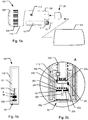
fig. 1 a is a schematic representation of a first embodiment of a medical injection system in accordance with the invention, -
fig. 1b schematically illustrates the working principle of a medical injection system according to the invention, -
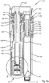
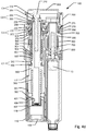
fig. 2a shows a cross sectional side view of a second embodiment of a medical injection system in accordance with the invention, -
fig. 2b is a magnified view of section A offig. 2a showing the main components of adose capturing unit 20, -
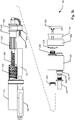
fig. 3a shows an exploded perspective view of the main components of theinjection device 100 offig. 2a , -
fig. 3b shows an exploded side view of the main components of theinjection device 100 offig. 2a , -
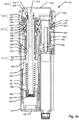
fig. 4a is a cross sectional side view of the device offig. 2a in an initial state before the setting of a dose, -
fig. 4b is a cross sectional side view of the device offig. 2a where adosage selector 200 has been operated to set a particular size of a dose, -
fig. 4c is a cross sectional side view of the device offig. 2a where aninjection button 300 has been pushed down and where the injection of the set dose has been completed, -
fig. 4d is a cross sectional side view of the device offig. 2a after the completion of the injection of the set dose and wherein the injection button has been released, -
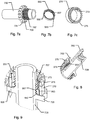
fig. 5a , shows a cross sectional side view of components relating to the drive mechanism of the device shown infig. 2a , -
fig. 5b is a perspective proximal view of the components shown infig. 5a , -
fig. 6 is a perspective proximal view of adose setting member 250 of the device shown infig. 2a , -
figs. 7a, 7b and 7c depict detailed perspective views ofcomponents -
fig. 8 shows a perspective cross sectional view of the components offigs. 7a, 7b and 7c in an assembled state, -
fig. 9 shows a perspective cross sectional partial view of components shown infig. 5b , -
fig. 10 is a perspective distal view of selected components offig. 5b , -
fig. 11 is a perspective proximal view of selected components relating to the dose setting and driving mechanism of theinjection device 100 offig. 2a , and -
fig. 12 is a schematic representation of the drive spring of theinjection device 100 offig. 2a . - The shown figures are schematic representations for which reason the configuration of the different structures as well as the relative dimensions are intended to serve illustrative purposes only.
- In that context it may be convenient to define that the term "distal end" in the appended figures is meant to refer to the end of the injection device which usually carries the injection needle whereas the term "proximal end" is meant to refer to the opposite end pointing away from the injection needle and carrying the dose dial button as depicted in
figure 1 a. -
Fig. 1a shows a schematic depiction of an embodiment of a medical injection system for use by a patient for medical self-treatment. The system comprises aninjection device 100 being configured for repetitively setting and injecting individually set doses of a drug.Fig. 1a shows a schematic representation of a first embodiment of amedical injection system injection device 100 includes ahousing 110 which along a main axis defines an elongated structure and which at least along a part of its length, in a direction transverse to the main axis, is formed with a non-cylindrical cross section exhibiting a somewhat flat shape, such a device being generally referred to as a "doser" device. Infig. 1a is further shown adose capturing unit 20 that in the depicted view is detached from theinjection device 100 but which is adapted to be replaceably fitted relative to theinjection device 100 by means of a coupling mechanism. - The
injection device 100 is shown as a cartridge-based injection device wherein a drug filledcartridge 10 is accommodated within thehousing 110. Referring tofig. 2a , thecartridge 10 may be of the type including an elongatedcylindrical body 11 and apierceable septum 12 covering a distal outlet end ofbody 11 for cooperation with a replaceablesubcutaneous injection needle 15. Also,cartridge 10 includes apiston 13 mounted withinbody 11 for sliding movement along an expelling axis of the cartridge, the expelling axis also defining the rotational longitudinal axis of thecartridge body 11. Either thecartridge 10 or thehousing 110 defines a needle mount adapted for releasably mounting aneedle assembly 15, e.g. a double pointed injection needle. When aneedle assembly 15 is mounted on thecartridge 10 so thatseptum 12 is pierced,piston 13 may be forced in the distal direction along the expelling axis for expelling portions of the drug accommodated incartridge 10. - The
injection device 100 shown infig. 1 further includes acap 160 which detachably mounts relative to the distal end ofhousing 110 for protection of the contents of thecartridge 10 and optionally for protecting an injection needle which may be mounted at the distal end of the device. - The
injection device 100 incorporates expelling means in the form of a drive mechanism incorporating means for setting a dose and means for expelling a set dose upon actuation of an actuator. The means for expelling a set dose incorporates a mechanical energy storage unit. The actuator includes aninjection button 300 arranged at the proximal end ofhousing 110 adapted to release energy from the mechanical energy storage unit to expel an amount of drug corresponding to the set dose. The means for setting a dose includes a dosage selector in the form of aflexible band 200 that encircles a section of thehousing 110 at the proximal end thereof. In the shown embodiment, during a dose setting process, theflexible band 200 may be manually gripped and turned in one direction relative tohousing 110 away from an initial position (the zero position) in order to dial up the set dose amount. In order to dial down an initially set dose theflexible band 200 may be turned in the opposite direction back towards the initial position. -
Housing 110 further includes a window or opening 170 which provides visual inspection to a mechanically based dose dial scale arranged internally inhousing 110. Dose dial scale may be provided as a drum shaped component that includes various printed indicia, such as numerals, arranged thereon, each indicia corresponding to the respective dose sizes that the dose setting part of drive mechanism is designed to assume. The dose dial scale is operated by means offlexible band 200 as it is turned relative to thehousing 110 during the dose setting process. - In embodiments where the injection device is adapted for injecting insulin-type medicaments, the dose size may be set as a multitude of fractional or integral numbers of International Units. Typically, the operable control member will have a max dose limit block up to a max dose limit (such as up to 60, 80 or 100 units) wherein a further increase in dose size is being prevented by a blocking mechanism incorporated in the drive mechanism of the
injection device 100. If the mechanism is designed to stop expelling when the user stops pushing theinjection button 300, the number display in the window will show the portion of the dose (e.g. the numbers of units) not yet expelled, e.g. 10 units of insulin. - The means for expelling a set dose includes a dosing member, i.e. a component (not shown) that during an expelling operation moves relative to another component of the
injection device 100. The extent of relative movement of the dosing member is indicative of the amount of drug of the dose expelled. - In the shown embodiment the
dose capturing unit 20 is formed to be received in an opening formed in the distal end face ofhousing 110 so that when thedose capturing unit 20 is coupled with theinjection device 100, a substantial part of thedose capturing unit 20 is accommodated within thehousing 110 ofinjection device 100. In the shown embodiment, thedose capturing unit 20 is inserted relative to the injection device along a coupling axis which is parallel to the longitudinal axis of the cartridge. Hence in such configuration thedose capturing unit 20 is placed alongside a needle mount (not shown) of theinjection device 100. - The
injection device 100 may include a latch mechanism (not shown) which is adapted for locking thedose capturing unit 20 in place once it has been fully inserted into the injection device. The latch mechanism may be configured so that the dose capturing unit snaps in place upon insertion intohousing 110 and configured so that when arelease button 180 formed at the distal end ofhousing 110 ofinjection device 100 is operated, thedose capturing unit 20 is coupled free from theinjection device 100. Hereafter, the dose capturing unit may be fitted onto a different injection device. Hence, thedose capturing unit 20 may be configured to be used either with a series of consecutive disposable devices, i.e. prefilled devices, or, alternatively, be used with a durable injection device, i.e. a device wherein the cartridge of the injection device is to be replaced by a new one after the contents of the cartridge has been expelled. - In other embodiments of the
dose capturing unit 20 and theinjection device 100, the coupling mechanism may include mutually cooperating coupling means different than the latch mechanism indicated above, for example where thedose capturing unit 20 incorporates a latch mechanism internally in a body section ofdose capturing unit 20. - The dose
data capturing unit 20 comprises electronic detection means for capturing data representing a property related to the amount of drug expelled from the cartridge by the expelling means, and optionally a switch means for initiating data capture, the switch means being actuated when theinjection button 300 is moved from its initial to its pushed down position. Thedose capturing unit 20 may also comprise a display (not shown) adapted to show e.g. time and dose size for the last expelling action, as well as a key allowing a user to e.g. toggle between a number of recent time-dose logs. Thedose capturing unit 20 may further be provided with an output port for wired or wireless upload of data to an external device, e.g. to the users smartphone or a doctors personal computer. -
fig. 1b schematically illustrates the working principle of a medical injection system according to the invention. As referred to above the system comprises theinjection device 100 which accommodates expelling means 101 insidehousing 110. The expelling means includes adosing member 350 that moves during expelling where the extent of movement is indicative of the amount of drug of the expelled dose. Upon actuation, the expelling means 101 moves one or more components, includingdosing member 350 by means of energy being released from a mechanical energy storage unit such as an energized spring, a compressed gas source or the like, i.e. providing an injection device of the auto-injector type. - In
fig. 1b , thedosing member 350 rotates during expelling of a dose. Optionally, thedosing member 350 rotates also during dose setting. For example, thedosing member 350 may rotate in one direction during dialing up a dose, whereas thedosing member 350 rotates in the opposite direction during dialing down a dose and during expelling of a dose. In addition, thedosing member 350 may be designed to move axially, for example during transition from a dose setting mode to a dose expelling mode and vice versa. - The injection system of the present invention includes the
dose capturing unit 20 that is coupled to thedosing member 350 of the injection device and adapted to sense the extent of movement by means of adose sensor 20d. When coupled to theinjection device 100, thedose capturing unit 20 acts to provide a force on the expelling means that acts counter to the force exerted by the mechanical energy unit. In the depicted embodiment, the counteracting force is adapted to act on thedosing member 350 but in other embodiments the counteracting force may be adapted to act on component of the expelling means other thandosing member 350. Compared to the situation where no dose capturing unit is coupled to the auto-injector, the combinedinjection device 100 and dose capturing unit 20 (i.e. "the combined apparatus") limits the speed of rotation occurring during expelling, at least for obtaining a limitation in the peak value of the speed obtained during the expelling movement. - The counteracting force emanating from the combined
injection device 100 and dose capturingunit 20 may be provided by various different principles either acting alone or in combination. Infig. 1b , "M" designates a mass that is coupled todosing member 350 and which due to being accelerated bydosing member 350 during expelling of a set dose acts to create a drag force ondosing member 350. Infig. 1b "F" designates a frictional force that is being applied on an element that rotates when thedosing member 350 rotates. Such friction may be obtained by a brake mechanism involving friction directly ondosing member 350 or alternatively involving friction acting on a component that is mounted withindose capturing unit 20 and being a part of dose capturing unit where this component rotates in synchronism with thedosing member 350 during the expelling action. - Exemplary speed limiting principles may be involved alone or in combination by configuring the combined apparatus to incorporate brake mechanisms such as an inertia brake, a friction brake, a fluidic brake, a magnetic brake, an eddy current brake and a centrifugal speed limiter. Other speed limiting mechanisms such as a clockwork movement may be provided. Such speed regulating means may include an escapement mechanism.
- Reference is now made to
fig. 2a which shows a cross sectional detailed side view of an example embodiment of amedical injection device 100 cooperating with an exampledose capturing unit 20 according to the invention.Fig. 2a only includes references referring to the main components. Exploded perspective and cross-sectional views of the main components of theinjection device 100 shown infig. 2a are depicted onfigs. 3a and3b . For further details to each of the components ofinjection device 100 reference is made to the remaining figures, in particularfigures 4a-4d . Thedose capturing unit 20 will be described further below in the closing part of the description section of the application. - The housing (110,120,130,140) comprises a
distal housing part 110, anintermediary housing part 120, aproximal housing part 130 and acartridge housing part 140. Further, as depicted infigures 4a-4d , a distal opening arranged adjacent the needle mount may include acover section 150 covering an internal cavity of the distal part of the housing. Thecover section 150 is removably attached todistal housing part 110. As described later thecover section 150 can be replaced by adose capturing unit 20 that is insertable into the internal cavity.Injection device 100 further comprises expelling means comprising a dose injection mechanism operable by aninjection button 300 and a dose setting mechanism operable by adosage selector 200. - The dose injection mechanism comprises a
piston rod 800 that engages the piston 13 (by means of a piston washer).Piston rod 800 extends axially in the proximal direction away frompiston 13. In the shown embodiment, thepiston rod 800 is of a flexible type having a piston engaging end and a free end wherein the flexibility is provided by forming the piston rod of a series of interconnected links. The flexibility allows the free end of the piston rod to be deflected away from the expelling axis. It is to be noted thatfig. 2a andfigs. 4a-4d only show the most distal part ofpiston rod 800, the remaining parts ofpiston rod 800 is for clarity reasons omitted from these drawings. However, the structure ofpiston rod 800 is more clearly depicted infigs. 3a and3b where it can be seen that, in the depicted operating state for thepiston rod 800, the piston engaging end of thepiston rod 800 assumes a straight portion while the free end assumes a bended portion. - In the shown embodiment, the
piston rod 800 is a segmented type rod that consists of interconnected hinged rod elements that are adapted to swivel relative to each other at least in a particular direction of rotation so that the free end of thepiston rod 800 may bend away from the expelling axis. When parts of thepiston rod 800 assume a straight configuration, the rod elements are substantially incompressible so that thepiston rod 800 is able to act as a push rod. Along its longitudinalextension piston rod 800 defines a first track and a second track each adapted to cooperate with a respective one of a nut member and a rotation control member so that relative rotation between the nut member and the rotational control member results in a longitudinal movement ofpiston rod 800. In alternative embodiments, the piston rod may be formed as a coiled axially incompressible spring which along its length is deflected away from its neutral rectilinear shape and that serves to transfer forces to the piston of the cartridge. - In the shown embodiment, the first track of the
piston rod 800 defines an external thread (not referenced) and the second track (not referenced) defines a rotation control geometry that cooperates with aguide member 112 formed indistal housing part 110 to ensure that at least the straight portion ofpiston rod 800 is kept substantially in-rotatable. The rotation control geometry of thepiston rod 800 may for example include one or more planar portions adapted to mate with a cooperating structure of theguide member 112 so as to prevent rotation between thepiston rod 800 and the cooperatingguide member 112. - As shown in
fig. 2a , the dose injection mechanism ofinjection device 100 comprises adrive nut 700 having aninternal thread 709 that engages the external thread of thepiston rod 800. Drivenut 700 is mounted rotatably free but axially fixed relative to the housing so thatdrive nut 700 is able to rotate around the expelling axis, the amount of rotation ofdrive nut 700 thereby being decisive for the axial distal displacement of the straight portion of the piston engaging end of thepiston rod 800. - The dose injection mechanism further includes a
drive member 500 that is mounted rotatable but axially fixed relative to the housing, thedrive member 500 being in rotational engagement withdrive nut 700 so that thedrive nut 700 rotates as thedrive member 500 rotates. An actuator providing a stored energy source exerts a substantially constant driving force ondrive member 500 in the particular direction of rotation that enables thepiston rod 800 to be driven in the distal direction. In the shown embodiment, the stored energy source comprises adrive spring 560 in the form of a flat spiral spring that initially is stored on astorage drum 600 and which spools onto thedrive member 500 as the energy accumulated in thedrive spring 560 is released for driving thepiston rod 800 in the distal direction. As regards further details of the drive mechanism reference is made to the discussion further below in relation tofigs. 10 and 11 . - As noted above,
injection device 100 further includes a dose setting mechanism allowing a user to set a desired dose to be injected by means of the dose injection mechanism. - Coupled to the dose setting mechanism and the dose injection mechanism is a clutch mechanism that ensures that during dose setting, no movement of the drive mechanism is possible and that ensures that during dose injection the dose setting cannot be manipulated to alter a dose setting that has previously been set. Hence the clutch mechanism defines the
injection device 100 to be operated in a dose setting mode and in a dose expelling mode. In the shown embodiment the clutch mechanism includes four separate clutch engagement mechanisms. Infigs. 4a-4d and in the following discussion these four clutch engagement mechanisms are respectively designated a first, second, third and fourth clutch engagement (C1, C2, C3, C4). - The
injection button 300 is arranged to protrude in a proximal direction from theproximal housing part 130 and arranged for limited axial movement between a default proximal position and a distal pressed down position. The mode of the clutch mechanism is controlled by theinjection button 300. When theinjection button 300 is depressed into the distal position theinjection device 100 is in dose expelling mode whereas when theinjection button 300 assumes its default proximal position the injection device is in dose setting mode. Theinjection button 300 is arranged relative to the housing of thedevice 100 so that theinjection button 300 cannot rotate. - The clutch mechanism includes a
drive clutch 370 mounted between thedrive member 500 and thehousing part 120 that controls whether or not drivemember 500 is allowed to rotate relative to the housing. The clutch mechanism will be described in greater detail further below. - The dose setting mechanism comprises a
dose setting member 250 that is manually operable by turningoperable dosage selector 200.Dose setting member 250 is axially fixed relative to the housing but rotates around an axis defining a dose setting axis that extends in parallel with the expelling axis but is separated from the expelling axis by a certain distance. Adosage selector connector 230 couples movement ofdosage selector 200 with rotation of thedose setting member 250 so that thedose setting member 250 may be rotated in either direction controlled by movement of thedosage selector 200. Betweendosage selector connector 230 anddose setting member 250, a slip coupling may be arranged to prevent destruction on the mechanism in case excessive forces are being applied ondosage selector 200. In the shown embodiment, as more clearly indicated onfig. 3a ,dosage selector 200 is arranged along a cross section transverse to the expelling axis of the housing i.e. betweenintermediary housing part 120 andproximal housing part 130. Dosage selector is formed as an endlessflexible band 200 that generally conforms to the shape of the exterior surfaces ofhousing parts housing parts flexible band 200 may be moved along the directions of circumference of the flexible band in a first direction to increase the setting of a dose and in the opposite direction for decreasing an already set dose. An interior surface of theflexible band 200 forms a series of teeth that cooperate withdosage selector connector 230 to transform movement offlexible band 200 into a rotation ofdose setting member 250. In other embodiments, instead of aflexible band 200 the dosage selector may be provided as a wheel or knob that may be manually turned for operating the dose setting mechanism. The dosage selector may for example be formed bydose setting member 250 by arranging openings in the housing of the device suitable formed to allow manual manipulation ofdose setting member 250. - Further, the above mentioned dosing member is defined by a
dose control member 350 that extends longitudinally along the dose setting axis. Thedose control member 350 is arranged in the housing for limited axial movements between a proximal position and a distal position. Apin 310 ofinjection button 300 extends distally frominjection button 300 along the dose setting axis and into an opening ofdose control member 350.Pin 310 serves to couple axial movements of theinjection button 300 with axial movements ofdose control member 350 but allows thedose control member 350 to be rotated around the dose setting axis. - A
compression spring 360 is arranged in the housing to exert a proximally directed force on thedose control member 350 to bias thedose control member 350 and hence theinjection button 300 into the proximal (default) position. - Positioned coaxially with the
dose control member 350 and indistal housing part 110 is adose dial scale 400 arranged. In the shown embodiment, thedose dial scale 400 is provided as a tubular sleeve that defines anexterior thread 407 engaging aninterior thread 117 formed in distal housing part 110 (seefig. 4a ). Along an exterior helical path, thedose dial scale 400 is provided with a series of numerals each referring to individually selectable doses of a drug that theinjection device 100 is designed to set and to expel.Housing part 110 is provided with an opening or window (not shown) through which a current dose setting is viewable. -
Dose dial scale 400 is adapted to rotate together with thedose control member 350 butdose dial scale 400 is movable in axial directions relative to dosecontrol member 350. In the shown embodiment this function is facilitated by means of an interior surface of thedose dial scale 400 that defines one or more axially extendingtracks 401 that cooperate with corresponding one or more axially extendingtracks 351 formed on an exterior surface of the dose control member 350 (seefig. 4a and11 ). -
Dose dial scale 400 includes a minimum limiting stop surface and a maximum limiting stop surface that define two extreme end positions that dose dial scale may assume during operation of theinjection device 100 preventing operation outside the two extreme end positions. As best viewed infig. 3b ,dose dial scale 400 includes said two stop surfaces as axially extending ledges (non-referenced) that each is adapted to cooperate with a respective dose stop surface defined bydistal housing part 110 andintermediary housing part 120. In the shown embodiment,dose dial scale 400 is adapted to experience a total rotation of 3.5 turns relative to the housing between a zero dose position and a maximum dose position. In the shown embodiment thedose dial scale 400 is provided with 100 separate dose markings along a helical path. -
Dose control member 350 serves several functions relating both to the dose setting mechanism and to the dose injection mechanism ofinjection device 100. - When the
injection device 100 is in dose setting mode, i.e. when theinjection button 300 is in the default proximal position,dose control member 350 couples a rotation of thedose setting member 250 with rotation of thedose dial scale 400. - When the
injection device 100 is in dose expelling mode, i.e. when theinjection button 300 is in the pushed down position, thedose control member 350 couples rotation of thedrive member 500 with rotation of thedose dial scale 400. -
Dose control member 350 further includes a resilient tooth 359 (seefig. 4a ) adapted to engage a series ofaxial splines 119 formed in thedistal housing part 110. Theresilient tooth 359 and the splines performs as a click mechanism that makes the dose setting occur in discrete steps, e.g. corresponding to the number of numerals provided on thedose dial scale 400. During dose setting, theinjection device 100 hereby emits a series of clicks as thedosage selector 200 is manipulated. In addition, as a dose of drug is being expelled, the click mechanism emits a series of click sounds as thedose control member 350 is rotated, e.g. one click as each unit of doses being expelled. Due to theaxial splines 119, thedose control member 350 is allowed to move axially without this having influence on the performance on the click mechanism. - Besides the above functions, also the function of the
drive clutch 370 is coupled with movements of thedose control member 350. In addition an end of content mechanism (EOC) including anEOC track follower 900 is coupled to the movement ofdose control member 350. As will be appreciated by a person skilled in the art, an end of content mechanism is a mechanism which prevents the setting of a dosage amount which exceeds the useable dose amount remaining in the drug cartridge. - The function of the
drive clutch 370 is provided by means of a second clutch engagement C2 (122, 372) between thedrive member 500 and theintermediary housing part 120.Drive member 500 and drive clutch 370 are rotationally locked relative to each other so that they rotate together but drive clutch 370 may be moved slightly in the axial direction relative to thedrive member 500. Between drive clutch 370 anddose control member 350 is a coupling which ensures that the axial movements ofdrive clutch 370 follows axial movements of thedose control member 350 but relative rotational movement between these two components is enabled. Drive clutch 370 includes a series ofteeth 372 adapted to engage correspondingteeth 122 formed in the intermediary housing part 120 (seefigs. 4a ,4c and11 ). Hence, when the injection button is in the proximal position, thedrive member 500 is locked relative to the housing so that rotation ofdrive member 500 is prevented. Upon depression ofinjection button 300, thedrive member 500 is released from the rotational locking relative to the housing allowing thedrive member 500 to rotate. Hence, only when the injection button is depressed thedrive member 500 is allowed to rotate and an expelling operation is enabled. - A first clutch engagement C1 (502, 352) is provided between the
drive member 500 and thedose control member 350. Thedrive member 500 defines a distal circular opening along which a series ofteeth 502 are arranged (seefigs. 4a and10 ). Thedose control member 350 includes a series ofcorresponding teeth 352. When thedose control member 350 is in its distal position (seefigs. 4c ), theteeth 352 ofdose control member 350 engage with theteeth 502 ofdrive member 500 to effectively lock the two components against relative rotation. Hence when theinjection button 300 is pushed down during dose injection, the rotation of thedrive member 500 is coupled with rotation ofdose control member 350. When thedose control member 350 is moved into its proximal position (seefigs. 4a ,4b and4d ), theteeth 352 are moved out of engagement with theteeth 502 ofdrive member 500. Hence when theinjection button 300 is released, rotation of thedose control member 350 relative to drivemember 500 is enabled. - A third clutch engagement C3 (253, 353) is provided between the
dose setting member 250 and the dose control member 350.The proximal part ofdose control member 350 includes a series of teeth 353 (seefig. 4a andfig. 11 ) adapted to engage correspondingteeth 253 formed in dose setting member 250 (seefigs. 4a ,5a and 6 ). When thedose control member 350 is in its proximal position, theteeth 353 ofdose control member 350 engage with theteeth 253 ofdose setting member 250. Hence, during dose setting, and when theinjection button 300 is in its released position as shown infig. 4a , thedose setting member 250 is coupled with thedose control member 350 so that these component rotate together. When thedose control member 350 is moved into its distal position as shown infig. 4c , theteeth 353 are moved out of engagement with theteeth 253 ofdose setting member 250. Hence when theinjection button 300 is pushed down, rotation of thedose control member 350 relative to dose settingmember 250 is enabled. - A fourth clutch engagement C4 (254, 314) is provided between the
dose setting member 250 and theinjection button 300.Dose setting member 250 defines a proximal circular opening along which a series ofteeth 254 are arranged (seefigs. 4a ,5a and 6 ). Thedistally extending pin 310 ofinjection button 300 includes a series of corresponding teeth 314 (seefigs. 4a-4d ). When thedose control member 350 is in its distal position (shown infig. 4c ), theteeth 314 ofinjection button 300 engage with theteeth 254 of thedose setting member 250 to prevent relative rotation betweendose control member 350 andinjection button 300.Button 300 is prevented from rotational movement relative toproximal housing part 130. Hence, when theinjection button 300 is pushed down, such as during dose injection, rotation of thedose setting member 250 relative to the housing is prevented. In the disclosed embodiment thedosage selector 200 cannot be operated during dose injection. When thedose control member 350 is moved into its proximal position (shown infigs. 4a ,4b and4d ), theteeth 314 are moved out of engagement with theteeth 254 of thedose setting member 250. Hence when theinjection button 300 is released, rotation of thedose setting member 250 relative to the housing is enabled which allows for a dose to be set by operatingdosage selector 200. - As shown in
figs. 4a ,5a and 5b thedrive member 500 includes a cylindrical section forming agear wheel 505. Also thedrive nut 700 includes a cylindrical section forming agear wheel 705 that engagesgear wheel 505. Hence a rotation ofdrive member 500 in a particular direction during dose injection is transferred to rotation in the opposite direction ofdrive nut 700. -
Figs. 10 and 11 show perspective representations of selected components of the drive mechanism included ininjection device 100. - The
drive member 500 includes a further cylindricalspring receiving section 550 that is arranged to reside next to thestorage drum 600 in the same axial position in the housing of the device as thestorage drum 600. Drivenut 700 provides a bearing surface adapted to receivestorage drum 600 so that storage drum may rotate independently relative to thedrive nut 700. In this embodiment, thedrive spring 560 is provided as a constant force spring arranged between thestorage drum 600 and the cylindricalspring receiving section 550 ofdrive member 500. Thespring 560 may be arranged to constitute an S-shaped curve in a manner schematically shown onfig. 12 . Thedrive spring 560 may be adapted to have a natural tendency to reside on thestorage drum 600. However, during production of theinjection device 100 thedrive spring 560 is forced onto the cylindricalspring receiving section 550 thereby accumulating energy indrive spring 560. Upon release, the accumulated energy of thedrive spring 560 urges drivemember 500 to rotate while thedrive spring 560 gradually winds up ontostorage drum 600. The cylindricalspring receiving section 550 includes means (non-referenced) to fasten the end of thedrive spring 560 so that slippage between thedrive spring 560 and drivemember 500 will not occur. - In other embodiments, the direction of movement may be reversed so that the
drive spring 560 may gradually seek to move onto thedrive member 500 during energy release, i.e. during dose expelling. Also other configurations of drive springs than the shown S-type spring may be used. - In the shown embodiment, the
drive spring 560 is fully loaded during the assembly of theinjection device 100. When purchased by the user, the drive spring contains sufficient energy to deliver the entire useable amount of drug contained in thecartridge 10. - During dose setting, the
dose control member 350 is rotated in accordance with the dose set as adjusted by means ofdosage selector 200. This has the effect that thedose dial scale 400 is rotated away from its zero dose position. The amount of rotation ofdose dial scale 400 therefore exactly corresponds to the selected dose size. During this movement the first clutch engagement C1 is in the released state so that thedrive member 500 is not being operated. It is noted that during dose setting, the second clutch engagement C2 is engaged meaning that thedrive member 500 is prevented from rotating. - The dose setting may be performed by dialling up and down
dosage selector 200 until a desired dose shows up in the dose window of the housing. After the desired dose has been dialled, and after an injection needle has been mounted relative to thedrug cartridge 10, the desired dose is ready for injection. - After applying a suitable force on the
injection button 300 to press down the injection button to the distal position, the first clutch engagement C1 is in the engaged state and the second clutch engagement C2 is in the released state. Hence, thedrive member 500 is released for rotation relative to the housing and is urged byspring drive 560 to rotate thereby carrying with it thedose control member 350. As long as theinjection button 300 is maintained in the depressed position, thedrive member 500, thedose control member 350 and thedose dial scale 400 rotate together towards the zero dose position. All this time thedrive nut 700 rotates to drive forward thepiston rod 800 resulting in the expelling of the drug through the attached needle. The movement is stopped when the minimum limiting stop surface of thedose dial scale 400 engages the corresponding dose stop surface formed indistal housing part 110. This simultaneously stops thedrive member 500 from rotating and thepiston rod 800 will move no further. - It is to be noted that during dose injection procedure, the expelling may be halted at any time by releasing pressure on the
injection button 300. The expelling may be continued by renewed pressing down theinjection button 300. - Hence the
dose dial scale 400 acts as a metering device during dose setting where the return movement of thedose dial scale 400 during injection determines the amount that will be expelled. In this way the dose dial scale provides a primary stop limiter. - The
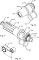
injection device 100 further includes a secondary stop limiter which performs as a safety back up function in case that a mechanical error occurs somewhere in the dose setting mechanism or somewhere in the dose injection mechanism. In the shown embodiment, thedrive nut 700 is associated with such a secondary stop limiter. As apparent fromfigs. 2a and in particularfigs. 5a-5b ,7a-7c, 8 and 9 the secondary stop limiter includes the saiddrive nut 700, asecondary stop ring 270 arranged coaxially with thedrive nut 700 and a secondarystop track follower 950 arranged between thedrive nut 700 andsecondary stop ring 270. - As shown in
fig. 7a , thedrive nut 700 includes anexternal thread 707 provided on a proximal cylindrical portion thereof. Thedrive nut 700 defines astop surface 708 located at a particular position relative to thethread 707. - Referring to
fig. 7b , the secondarystop track follower 950 is in this embodiment in the form of a cylindrical nut that defines aninternal thread 957 adapted to engage thethread 707 ofdrive nut 700. Thesecondary track follower 950 defines astop surface 958 that is adapted to engage thestop surface 708 provided ondrive nut 700 for a particular relative rotational and axial position between the secondarystop track follower 950 and drivenut 700. The secondarystop track follower 950 further comprises one ormore track elements 953 extending radially outwards from an outer cylindrical surface of secondarystop track follower 950. - As shown in
fig. 7c . thesecondary stop ring 270 is a generally cylindrical sleeve that includes a cylindrical bearing surface (non-referenced) adapted to be rotatably supported in the housing at a fixed location thereof. An interior surface of thestop ring 270 includes one or more axially extendingtracks 273 each of which is adapted to cooperate with respective ones oftrack elements 953 of the secondarystop track follower 950. In this way the secondarystop track follower 950 is configured to rotate with thesecondary stop ring 270 but allows relative axial displacement of secondarystop track follower 950 relative tosecondary stop ring 270. A cylindrical section ofsecondary stop ring 270 forms agear wheel 275 that is adapted to engage thegear wheel 255 section ofdose setting member 250. - In the assembled state the
drive nut 700, thesecondary stop ring 270 and the secondarystop track follower 950 forms an assembly that more easily is viewed infigs. 5a ,8 and 9 . - Due to the threaded engagement between the secondary
stop track follower 950 and thedrive nut 700, the secondarystop track follower 950 will be moved back and forth in the axial direction as the secondarystop track follower 950 and thedrive nut 700 rotate relative to each other. - Before the setting of a dose, when the
dose dial scale 400 indicates its zero dose setting through the window in the housing, the secondarystop track follower 950 will assume an initial position relative to thedrive nut 700. In this state thestop surface 958 of thesecondary track follower 950 will be situated in close proximity with respect to thestop surface 708 provided ondrive nut 700. As a dose is dialled up by manipulatingdosage selector 200 thedose setting member 250 will be rotated and, due to the engagement betweengear wheel 255 andgear wheel 275, thesecondary stop ring 270 and thesecondary track follower 950 will be rotated as well. As thedrive nut 700 is maintained non-rotatable during dose setting, due to the threadedconnection secondary track follower 950 will be moved in the proximal direction so that thestop surface 958 of thesecondary track follower 950 will be moved further away from thestop surface 708 provided ondrive nut 700. - During dose injection, when the
injection button 300 is pressed down, thedose setting member 250 is prevented from rotating and hence thesecondary stop ring 270 and thesecondary track follower 950 are prevented from rotating as well. However, as thedrive nut 700 rotates during injection, due to the threadedconnection secondary track follower 950 will be moved in the distal direction. - In a correctly working
injection device 100, upon reaching the end of dose state where thedose dial scale 400 is located so that its minimum limiting surface engages the corresponding dose stop surface defined by the distal housing part 110 (corresponding to the zero dose position), thesecondary track follower 950 will be moved to assume the initial position as referred to above. In this position thestop surface 958 of thesecondary track follower 950 will again be situated in close proximity with respect to thestop surface 708 provided ondrive nut 700. - In case a mechanical failure occurs in the injection device, such as a failing primary stop limiter, a failing first clutch engagement C1 or a failing second clutch engagement C2, the biasing force exerted by the
drive spring 560 ondrive member 500 may cause the drive member to run freely causing thedrive nut 700 to rotate and thepiston rod 800 to move in the distal direction in an uncontrolled manner. However should such a situation arise, thedrive nut 700 may slightly rotate but soon the secondary stop limiter will prevent further rotation ofdrive nut 700 as thestop surface 958 of thesecondary track follower 950 will be in abutment with thestop surface 708 provided ondrive nut 700. - In the shown embodiment, the
drive nut 700 defines athread 707 whereas thestop ring 270 defines one or more axially extendingtracks 273 where thethread 707 and thetracks 273 engage corresponding structures on thesecondary track follower 950. A similar function may be obtained by rearranging the thread to be disposed on thestop ring 270 and the axially extending tracks to be disposed on thedrive nut 700 and rearranging the structures on thesecondary track follower 950 accordingly. In still other embodiments, thesecondary track follower 950 defines two threaded sections where each of the threaded sections operate with corresponding threads formed on thedrive nut 700 and thestop ring 270 respectively. In such embodiment, the two threaded engagements are provided with differently pitched threads so that thesecondary track follower 950 is forced to move axially as thedrive nut 700 and thestop ring 270 rotate relative to each other. - In the shown embodiment, the
secondary track follower 950 is formed as a cylindrical nut. In alternative embodiments, thesecondary track follower 950 may alternatively be provided as a half-nut or forming another structure such as ball clamped between tracks formed in thedrive nut 700 and thestop ring 270 where the tracks have different pitches. - The above mentioned end of content (EOC) mechanism will now be more fully described referring generally to
fig. 4a . In the shown embodiment, thedose control member 350 includes one or more longitudinal extendingribs 354 provided along an exterior cylindrical surface thereof. Thedrive member 500 includes an interior cylindrical surface that defines aninterior thread 507. And end of content track follower (EOC track follower) 900 is formed as a cylindrical nut and arranged coaxially with thedrive member 500 and thedose control member 350 so that the EOC track follower is located between thedrive member 500 and thedose control member 350. TheEOC track follower 900 defines anexternal thread 907 that cooperates withinternal thread 507 ofdrive member 500.EOC track follower 900 further defines one or more internal axial recesses each adapted to cooperate with the one or more longitudinal extendingribs 354 ofdose control member 350. - A not shown EOC limitation stop is associated with a proximal part of the
thread 507 ofdrive member 500. In a known manner such stop may define a rotational stop surface adapted to engage a rotational stop surface (not shown) of theEOC track follower 900 for a particular relative axial and rotational position between theEOC track follower 900 and thedrive member 500. The said EOC limitation stop limits the movement of theEOC track follower 900 in the proximal direction so that the settable size of the dose is limited to dosage amounts to which a corresponding dosage remains in thecartridge 10. In this way thedosage selector 200 cannot dial up a dose that is larger than the remaining useable dose accommodated in the cartridge. - Prior to use of the injection device, where the
cartridge 10 is full and thepiston rod 800 is located in the position shown onfig. 4a , theEOC track follower 900 is positioned in an initial axial position relative to the housing (seefig. 4a ). During dialling up a dose theEOC track follower 900 is rotated as thedose control member 350 rotates relative to thedrive member 500. Due to the threadedengagement fig. 4b ). Should thedosage selector 200 be moved for dialling down a previously set dose, theEOC track follower 900 will move in the distal direction in accordance with the reduction in dose size. - When an injection is initiated, the
dose control member 350 will move to its distal position. This has no influence on the axial position of theEOC track follower 900. During injection wherein the first clutch engagement C1 is in the engaged state, thedose control member 350 rotates along with thedrive member 500. Hence, during this procedure, theEOC track follower 900 will retain its position relative to thethread 507 defined by the drive member 500 (seefig. 4c ). - Finally, after the dose injection has been completed, the
injection button 300 is released and the first clutch engagement C1 is disengaged and the second clutch engagement C2 is engaged. Again, this has no influence on the axial position of the EOC track follower 900 (seefig. 4d ). - After additional subsequent dose setting and dose injection procedures the EOC track follower will move gradually in the proximal direction in accordance with the accumulated dialling up procedures during each of the performed administrations. As noted above, at a predetermined point the EOC track follower will abut an EOC limitation stop which will prevent further dialling up. Hereby the user is notified that the cartridge does not contain sufficient doses above a certain limit.
- As noted above the
fig. 4a shows the device in an initial state before the setting of a dose,fig. 4b shows the device in a state where thedosage selector 200 has been operated to set a particular size of a dose,fig. 4c shows the device in a state where theinjection button 300 has been pushed down and where the injection of the set dose has been completed and, finally,fig. 4d shows the device in a state after completion of the injection of the set dose and where theinjection button 300 has been released. - By comparing states shown in the
figures 4a ,4b ,4c and4d , the movement of each of the clutch engagements C1, C2, C3 and C4 will become evident. Also, in accordance with the above description, the particular movements of the EOC mechanism and the secondary stop limiter providing the safety mechanism will become evident. - Turning now to
fig. 2b , thedose capturing unit 20 will be further described. Thedose capturing unit 20 includes abody section 20k configured for cooperating with thedistal housing part 110 to retain thedose capturing unit 20 relative to theinjection device 100. Anelectronic display 20g is arranged at a distal portion ofdose capturing unit 20 so that information provided on the display is visible through a transparent distal surface of thebody section 20k. Acircuit board 20f is arranged within thebody section 20k and includes various electronic components such as amicrocontroller 20i, one or more sensors, abattery 20h and various connectors for connecting further components arranged remotely from the circuit board. - A
rotatable mass unit 20a is arranged to be rotatable around the dose setting axis, i.e. coaxially withdose control member 350 and configured to physically engage and lock rotationally relative to thedose control member 350. Therotatable mass unit 20a is made of a material having such a weight that the presence of thedose capturing unit 20 with therotatable mass unit 20a limits the peak expelling speed experienced during a dose expelling procedure. In the shown embodiment, also a friction basedbrake pad 20j acts on therotatable mass unit 20a to limit the rotational speed of thedose control member 350. Alternatively, the brake providing the counteracting force may be formed by suitably providing a frictional engagement with ashaft 20b discussed below. As noted above, other types of speed limiting mechanisms may be provided as an alternative or in addition to the ones shown infig. 2b . - A
rotatable identifier 20c is connected by means ofshaft 20b to therotatable mass unit 20a. In the shown embodiment, therotatable identifier 20c includes a multi-pole magnetic ring. In this embodiment aHall element sensor 20d is arranged next torotatable identifier 20c. Thus a magnetic linear encoder is provided decoding the rotation of the magnetic ring. As the magnetic ring follows rotation of thedose control member 350, the rotational positions or movements of thedose control member 350 can be captured by means of the magnetic linear encoder. - In the shown embodiment, a
switch 20e is arranged to sense the axial position of thedose control member 350 and hence provides information as to whether the injection device is in dose setting mode or in dose expelling mode. The size of a dose is calculated based on the incremental angle measured while thedose control member 350 rotates while it remains in a current mode of operation. Hence, the electronics of the dose capturing unit is able to capture information relating both to positional information and/or movements occurring during dose setting but also during expelling of a set dose and is able to discriminate between data obtained in to the two operation modes of theinjection device 100. - The
electronic display 20g may be configured to display the current dose setting of the injection device and/or the amount of drug that has been expelled during the last expelling operation. Thedose capturing unit 20 further includes a memory configured for holding dose size and related timing information for the last expelling action, and optionally a number of recent time-dose logs. The dose capturing unit may further be provided with an output port for wired or wireless upload of data to an external device, e.g. to the users smartphone or a doctors personal computer.Electronic display 20g may in some embodiments be omitted so that thedose capturing unit 20 only serves as an information storage that enables upload of the time-dose log to an external device. - The measuring principle of the
dose capturing unit 20 may be provided by other suitable encoding technology adapted to capture rotational and/or axial information of thedose control member 350. Likewise, such encoding technology could be adapted to monitor movements of other components of the device such as theEOC track follower 900. Hence, the above described magnetic linear encoder may be substituted by other encoders using such as optics, galvanic contacts, induction, capacitive coupling or potentiometer type sensors. The rotary position encoder may be configured as a relative sensor or an absolute sensor. When the encoders use optical sensors or galvanic contacts, the identifier may be in the form of a Gray code pattern, either as a drum-shaped pattern arrange on a radially outwards facing or a radially inwards facing cylindrical surface or on a plane surface of a circular disk. - A rotatable identifier may be arranged in the
dose capturing unit 20 as a component that belongs to thedose capturing unit 20 and wherein the rotatable identifier directly couples to the dose control member 350 (as shown infig. 2a ). Alternatively the rotatable identifier couples to dosecontrol member 350 via one or more gear-wheels. Other embodiments may include the rotatable identifier to be integrated into theinjection device 100, such as integrated into or arranged ontodose control member 350 so that thedose sensor 20d ofdose capturing unit 20 directly senses rotational information provided on thedose control member 350. - In other embodiments, the dosing member according to the invention may be defined by a component other than the
dose control member 350 provided such component moves to an extent corresponding to the extent of movement of thepiston rod 800 during the expelling of a set dose. As an example, the device shown infig. 2a may be modified to allow the rotary position of thedrive member 500 to be captured by thedose capturing unit 20. As thedrive member 500 only rotates during expelling of a set dose, theabove switch 20e may be omitted as the rotation performed by drive member may be directly captured to obtain data relating to the amount of expelled doses. Such an embodiment provides for a particularly simple and inexpensive solution. However, in embodiments that are configured for capturing the rotational position ofdrive member 500, the axial position of thedose control member 350 may in some circumstances be utilized for waking up the rotational dose sensor upon the injection device being shifted from the dose setting mode to the dose expelling mode. - In the embodiment shown on the figures, the injection device defines a pre-filled injection device where a drug filled cartridge is arranged irremovably within the device. Subsequent to expelling the entire contents of the cartridge the pre-filled injection device is intended to be disposed of and, optionally, be replaced by a new disposable device. However, in other embodiments being slightly modified, the injection device may be adapted to be used as a device of the durable kind, wherein a first cartridge is replaced by a new one when the first cartridge has been emptied.
- In line with the invention as set forth above, the invention is generally applicable to medical delivery devices, regardless of the kind of administration route for delivering a beneficial agent to the user. Also, the invention may be implemented in both manual injectors where the user directly delivers the necessary mechanical energy during the delivery process as well as spring assisted injectors where a pre-stressed or user strained spring in part or fully delivers the necessary mechanical energy during the delivery process. Further, the invention may be used in connection with other medical injection devices where actuators having other energy sources than spring actuators are used, such as pneumatically operated actuators having a pneumatic storage, prime mover actuators having an electrochemical cell storage or even electrical actuators having an electrical accumulator storage.
- In the above description of the exemplary embodiments, the different structures providing the desired relations between the different components just as the means providing the described functionality for the different components have been described to a degree to which the concept of the present invention will be apparent to the skilled reader. The detailed construction and specification for the different structures are considered the object of a normal design procedure performed by the skilled person along the lines set out in the present specification.
Claims (15)
- A medical injection system, comprising an injection device (100) configured for setting and expelling a set dose amount of a drug from a reservoir (10), and an electronically controlled dose capturing means (20) configured for capturing data relating to expelling of drug from the injection device (100),
wherein the injection device (100) comprises:- a housing (110,120,130,140),- expelling means (101) for expelling an amount of drug from the reservoir (10), comprising:wherein the expelling means (101) defines a dosing member (350, 500) that moves relative to another component of the injection device (100) during expelling of the set dose amount, the extent of relative movement being indicative of the amount of drug being expelled, and(i) setting means (200, 250, 400) allowing a user to set a dose amount of drug to be expelled,(ii) actuation means (300) for releasing the drug expelling means to expel the set dose amount, and(iii) a mechanical energy storage unit (560) coupled to the actuation means (300) which upon release exerts a driving force for driving the expelling means to expel the set dose amount when the actuation means (300) is actuated,
wherein the electronically controlled dose capturing means (20) comprises a dose sensor (20d) adapted to sense said relative movement performed by the dosing member (350) to capture data representing the extent of relative movement of the dosing member (350, 500) during expelling of the set dose amount,
characterized in that the electronically controlled dose capturing means are provided as a dose capturing unit (20) configured for being attached relative to the injection device (100), and
wherein the dose capturing unit (20) when attached relative to the injection device (100) couples to the expelling means (101) to exert a counteracting force to the force exerted by the mechanical energy storage unit (560) to limit the speed of relative movement of the dosing member (350, 500) during expelling of the set dose amount. - A medical injection system as defined in claim 1, wherein the dose capturing unit (20) defines a body (20k) that accommodates the dose sensor (20d), and wherein the body (20k) of the dose capturing unit (20) is releasably attachable relative to the injection device (100).
- A medical injection system as defined in any of the claims 1 or 2, wherein the injection device (100) is so configured that, when the dose capturing unit (20) is not attached relative to the injection device (100), the injection device (100) is operable allowing the user to set a dose amount to be expelled and to expel a set dose amount.
- A medical injection system as defined in any of the claims 1 or 2, wherein the dose capturing unit (20) attaches non-detachably relative to the injection device (100) to form an integrated part of the injection device.
- A medical injection system as defined in any of the claims 1-4, wherein the dose capturing unit (20) comprises a movable mass (20a, 20b, 20c" M) that couples to the expelling means so that the movable mass (20a, 20b, 20c, M) is moved when the expelling means is operated for providing said counteracting force.
- A medical injection system as defined in any of the claims 1-5, wherein the dose capturing unit (20) couples to the expelling means (101) to provide a frictional force (F) for providing said counteracting force.
- A medical injection system as defined in any of the claims the claims 1-6, wherein the dose capturing unit (20) comprises one or more components (20a, 20b, 20c) that mechanically or magnetically engages with a component of the expelling means (101) when the dose capturing unit (20) is attached to the injection device (100).
- A medical injection system as defined in claim 7, wherein the dose capturing unit (20) comprises one or more components (20a, 20b, 20c) that mechanically engages with the dosing member (350, 500) of the injection device (100) when the dose capturing unit (20) is attached to the injection device (100).
- A medical injection system as defined in any of the claims 1-8, wherein the dosing member (350, 500) of the injection device (100) is a component that performs a rotating movement during expelling of a set dose amount.
- A medical injection system as defined in any of the claims 1-9, wherein the dose capturing unit (20), when attached to the injection device (100), defines a speed limiting mechanism for providing said counteracting force, the speed limiting mechanism incorporating one or more of the speed limiting mechanisms selected from the group consisting of a friction speed limiter, an inertia speed limiter, a fluidic speed limiter, an eddy current speed limiter and a centrifugal speed limiter.
- A medical injection system as defined in any of the claims 1-10, wherein the reservoir (10) of the injection device (100) is a cylindrical cartridge having a piston (13) movable in a distal direction towards an expelling end of the cartridge, wherein a central longitudinal axis of the cartridge defines a first axis, wherein the dosing member (350, 500) is rotatable around a second axis that is spaced relative to the first axis, and wherein the dose capturing unit attaches to the injection device at a distal end of the housing (110, 120, 130, 140) of the device.
- A medical injection system as defined in any of the claims 1-11, wherein when the dose capturing unit (20) is attached relative to the housing (110, 120, 130, 140) of the injection device (100) the exterior housing defined by the combined apparatus defined by the injection device (100) and the dose capturing unit (20) includes a distal facing surface that is defined by a component of the dose capturing unit (20).
- A medical injection system as defined in any of the claims 1-12, wherein the mechanical energy storage unit (560) is a spring device that is strained to accumulate energy and wherein the accumulated energy upon actuation of the actuation means (300) is released to drive the expelling means (101) to expel the set dose amount.
- A medical injection system as defined in claim 13, wherein the dose setting means comprises a movable dosage selector (200) and wherein the spring device (560) is strained when the dosage selector (200) is operated to dial up a dose.
- A medical injection system as defined in claim 13, wherein the mechanical energy storage unit (560) comprises energy sufficient to drive the expelling means (101) for expelling the entire useable contents of the reservoir (10).
Priority Applications (1)
| Application Number | Priority Date | Filing Date | Title |
|---|---|---|---|
| EP14700579.7A EP2943236B1 (en) | 2013-01-10 | 2014-01-10 | Medical injection system with dose capturing |
Applications Claiming Priority (4)
| Application Number | Priority Date | Filing Date | Title |
|---|---|---|---|
| EP13150893 | 2013-01-10 | ||
| US201361752024P | 2013-01-14 | 2013-01-14 | |
| EP14700579.7A EP2943236B1 (en) | 2013-01-10 | 2014-01-10 | Medical injection system with dose capturing |
| PCT/EP2014/050363 WO2014108494A1 (en) | 2013-01-10 | 2014-01-10 | Medical injection system with dose capturing |
Publications (2)
| Publication Number | Publication Date |
|---|---|
| EP2943236A1 EP2943236A1 (en) | 2015-11-18 |
| EP2943236B1 true EP2943236B1 (en) | 2017-05-10 |
Family
ID=47627984
Family Applications (1)
| Application Number | Title | Priority Date | Filing Date |
|---|---|---|---|
| EP14700579.7A Active EP2943236B1 (en) | 2013-01-10 | 2014-01-10 | Medical injection system with dose capturing |
Country Status (5)
| Country | Link |
|---|---|
| US (1) | US10117999B2 (en) |
| EP (1) | EP2943236B1 (en) |
| JP (1) | JP6423362B2 (en) |
| CN (1) | CN104884105B (en) |
| WO (1) | WO2014108494A1 (en) |
Families Citing this family (30)
| Publication number | Priority date | Publication date | Assignee | Title |
|---|---|---|---|---|
| WO2014111337A1 (en) | 2013-01-15 | 2014-07-24 | Sanofi-Aventis Deutschland Gmbh | Supplemental device for attachment to a medical injection device for generating usage reports about use of the injection device in digital image format |
| DE202013000411U1 (en) * | 2013-01-16 | 2013-01-24 | H & B Electronic Gmbh & Co. Kg | Continuous infusion device |
| US10092705B2 (en) * | 2013-04-10 | 2018-10-09 | Sanofi | Injection device |
| DK2983759T3 (en) * | 2013-04-10 | 2018-02-12 | Sanofi Sa | INJECTION DEVICE |
| CN106714878B (en) * | 2014-10-03 | 2020-04-21 | 诺和诺德股份有限公司 | Pen-shaped drug injector with magnetic dose sensor system and error detection and add-on module |
| EP3162395A1 (en) | 2015-10-28 | 2017-05-03 | NNE Pharmaplan A/S | Single-use auto-injector |
| DE102016101173B4 (en) * | 2016-01-22 | 2020-01-30 | Carl Zeiss Industrielle Messtechnik Gmbh | INTERCHANGEABLE DEVICE WITH CATCHER |
| EP3407940A4 (en) | 2016-01-29 | 2019-09-04 | Companion Medical, Inc. | Automatic medication delivery tracking |
| US9636464B1 (en) * | 2016-08-01 | 2017-05-02 | Innovative Precision Instruments Limited | Drug delivery device and a drug information detection device |
| CN107789706B (en) * | 2016-09-06 | 2021-12-03 | 广东东阳光药业有限公司 | Data acquisition method and acquisition structure for injector, injector and injection system |
| GB201615446D0 (en) * | 2016-09-12 | 2016-10-26 | Norton Healthcare Ltd | Dose delivery mechanism |
| MX2019010214A (en) | 2017-02-28 | 2019-10-09 | Lilly Co Eli | Dose detection and drug identification for a medication delivery device. |
| CA176748S (en) * | 2017-03-03 | 2018-07-23 | Vetter Pharma Fertigung Gmbh & Co Kg | Injection device |
| EP3684447B1 (en) | 2017-09-22 | 2022-07-13 | Novo Nordisk A/S | Accessory device for drug delivery device |
| CN112604089B (en) | 2017-11-23 | 2024-02-06 | 赛诺菲 | Medicament injection apparatus with rotary encoder |
| CN111417425B (en) * | 2017-12-04 | 2022-07-08 | 诺和诺德股份有限公司 | Drug delivery system with multi-pole magnet and sensor system |
| US10987464B2 (en) | 2017-12-12 | 2021-04-27 | Bigfoot Biomedical, Inc. | Pen cap for insulin injection pens and associated methods and systems |
| US11116899B2 (en) | 2017-12-12 | 2021-09-14 | Bigfoot Biomedical, Inc. | User interface for diabetes management systems and devices |
| US11090439B2 (en) | 2017-12-12 | 2021-08-17 | Bigfoot Biomedical, Inc. | Therapy management systems, methods, and devices |
| US11464459B2 (en) | 2017-12-12 | 2022-10-11 | Bigfoot Biomedical, Inc. | User interface for diabetes management systems including flash glucose monitor |
| US11077243B2 (en) | 2017-12-12 | 2021-08-03 | Bigfoot Biomedical, Inc. | Devices, systems, and methods for estimating active medication from injections |
| US11083852B2 (en) | 2017-12-12 | 2021-08-10 | Bigfoot Biomedical, Inc. | Insulin injection assistance systems, methods, and devices |
| JP7069330B2 (en) | 2018-02-22 | 2022-05-17 | イーライ リリー アンド カンパニー | Drug delivery device with a device to be detected |
| CN108837196B (en) * | 2018-07-26 | 2020-09-08 | 陈澜涛 | Needle cylinder capable of realizing constant-speed suction |
| US11229749B2 (en) * | 2018-09-06 | 2022-01-25 | Verily Life Sciences Llc | Plate capacitor for dosage sensing |
| CN111692245A (en) * | 2019-03-11 | 2020-09-22 | 张甫州 | Braking mode |
| US11948671B2 (en) | 2019-04-11 | 2024-04-02 | Medtronic Minimed, Inc. | Intelligent accessories for medicine dispensing device |
| WO2020212499A1 (en) * | 2019-04-18 | 2020-10-22 | Sanofi | Apparatus for detecting a dose of medicament delivered from an injection device |
| TWI801852B (en) * | 2020-05-22 | 2023-05-11 | 達爾生技股份有限公司 | Dose recorder and dose recording method thereof |
| CN112915318B (en) * | 2021-01-26 | 2022-09-23 | 刘苏衡 | Needleless injection device |
Family Cites Families (14)
| Publication number | Priority date | Publication date | Assignee | Title |
|---|---|---|---|---|
| US4959056A (en) | 1988-06-14 | 1990-09-25 | Wayne State University | Digital dispenser |
| US4921487A (en) | 1988-09-21 | 1990-05-01 | Compagnie Financiere Saint. Nicolas | External device for injecting medicine |
| ATE209052T1 (en) | 1993-06-30 | 2001-12-15 | Hamilton Co | MANUAL DISPENSING AID FOR AN INJECTION SYRINGE |
| JP2003180828A (en) | 2001-12-21 | 2003-07-02 | Matsushita Electric Ind Co Ltd | Electric fluid discharging apparatus |
| DE20309262U1 (en) | 2003-06-16 | 2003-08-21 | Health & Life Co | Data storage unit for integrated storage of data from a number of medical instruments has display, control and warning units so that evaluated data can be used to generate an alarm and medical personnel can readily access data |
| US8052655B2 (en) | 2006-09-29 | 2011-11-08 | Novo Nordisk A/S | Injection device with electronic detecting means |
| GB2443390A (en) * | 2006-11-03 | 2008-05-07 | Owen Mumford Ltd | Medicine delivery apparatus |
| EP2060284A1 (en) | 2007-11-13 | 2009-05-20 | F.Hoffmann-La Roche Ag | Medical injection device having data input means and a pivotable display |
| DE102008011881A1 (en) | 2008-02-29 | 2009-09-10 | Tecpharma Licensing Ag | Empty shooting speed limit brake |
| TR201808203T4 (en) * | 2008-11-06 | 2018-07-23 | Novo Nordisk As | Electronic assisted drug delivery device. |
| DE202009001836U1 (en) * | 2009-02-13 | 2009-05-20 | Dieter Hölzle Technik-Projekte GmbH | Electromechanical injection device |
| CN107412916A (en) * | 2009-02-27 | 2017-12-01 | 生命扫描有限公司 | Delivery system |
| US20100286612A1 (en) | 2009-05-06 | 2010-11-11 | William Cirillo | Medication injection supervisor device |
| CN103917263B (en) | 2011-11-08 | 2016-08-24 | 诺沃—诺迪斯克有限公司 | Including medical injection device and the medical infusion system of dosage limiter block |
-
2014
- 2014-01-10 JP JP2015552054A patent/JP6423362B2/en active Active
- 2014-01-10 WO PCT/EP2014/050363 patent/WO2014108494A1/en active Application Filing
- 2014-01-10 US US14/759,558 patent/US10117999B2/en active Active
- 2014-01-10 CN CN201480004593.7A patent/CN104884105B/en active Active
- 2014-01-10 EP EP14700579.7A patent/EP2943236B1/en active Active
Also Published As
| Publication number | Publication date |
|---|---|
| JP2016502898A (en) | 2016-02-01 |
| WO2014108494A1 (en) | 2014-07-17 |
| EP2943236A1 (en) | 2015-11-18 |
| US20150352288A1 (en) | 2015-12-10 |
| US10117999B2 (en) | 2018-11-06 |
| CN104884105B (en) | 2018-01-19 |
| JP6423362B2 (en) | 2018-11-14 |
| CN104884105A (en) | 2015-09-02 |
Similar Documents
| Publication | Publication Date | Title |
|---|---|---|
| EP2943236B1 (en) | Medical injection system with dose capturing | |
| EP2958611B1 (en) | Rotary sensor module with axial switch | |
| EP2958610B1 (en) | Dose capturing cartridge module for drug delivery device | |
| CN110958897B (en) | Dose detection module for a drug delivery device | |
| EP2958612B1 (en) | Drug delivery device with dose capturing module | |
| EP3463520B1 (en) | Mounting feature for accessory device | |
| EP2981312B1 (en) | Logging device adapted to combine doses | |
| EP2838586B1 (en) | Medical injection device comprising a secondary safety limiter | |
| WO2017148855A1 (en) | Switch arrangement for drug delivery device with data capture | |
| JP7201435B6 (en) | Power efficient accessory device | |
| EP3322461B1 (en) | Pen-type drug injector with end-of-dose sensor and system for registering the delivered dose | |
| EP3209351A1 (en) | Pen-type drug delivery device with electronic display on clip member | |
| US20220370723A1 (en) | Dose setting assembly with slack reducing feature | |
| WO2023169924A1 (en) | Dose logging assembly with rotational transmission feature |
Legal Events
| Date | Code | Title | Description |
|---|---|---|---|
| PUAI | Public reference made under article 153(3) epc to a published international application that has entered the european phase |
Free format text: ORIGINAL CODE: 0009012 |
|
| 17P | Request for examination filed |
Effective date: 20150810 |
|
| AK | Designated contracting states |
Kind code of ref document: A1 Designated state(s): AL AT BE BG CH CY CZ DE DK EE ES FI FR GB GR HR HU IE IS IT LI LT LU LV MC MK MT NL NO PL PT RO RS SE SI SK SM TR |
|
| AX | Request for extension of the european patent |
Extension state: BA ME |
|
| DAX | Request for extension of the european patent (deleted) | ||
| GRAP | Despatch of communication of intention to grant a patent |
Free format text: ORIGINAL CODE: EPIDOSNIGR1 |
|
| INTG | Intention to grant announced |
Effective date: 20160913 |
|
| GRAJ | Information related to disapproval of communication of intention to grant by the applicant or resumption of examination proceedings by the epo deleted |
Free format text: ORIGINAL CODE: EPIDOSDIGR1 |
|
| GRAP | Despatch of communication of intention to grant a patent |
Free format text: ORIGINAL CODE: EPIDOSNIGR1 |
|
| INTC | Intention to grant announced (deleted) | ||
| INTG | Intention to grant announced |
Effective date: 20161123 |
|
| GRAS | Grant fee paid |
Free format text: ORIGINAL CODE: EPIDOSNIGR3 |
|
| GRAA | (expected) grant |
Free format text: ORIGINAL CODE: 0009210 |
|
| AK | Designated contracting states |
Kind code of ref document: B1 Designated state(s): AL AT BE BG CH CY CZ DE DK EE ES FI FR GB GR HR HU IE IS IT LI LT LU LV MC MK MT NL NO PL PT RO RS SE SI SK SM TR |
|
| REG | Reference to a national code |
Ref country code: GB Ref legal event code: FG4D |
|
| REG | Reference to a national code |
Ref country code: AT Ref legal event code: REF Ref document number: 891642 Country of ref document: AT Kind code of ref document: T Effective date: 20170515 Ref country code: CH Ref legal event code: EP |
|
| REG | Reference to a national code |
Ref country code: IE Ref legal event code: FG4D |
|
| REG | Reference to a national code |
Ref country code: DE Ref legal event code: R096 Ref document number: 602014009634 Country of ref document: DE |
|
| REG | Reference to a national code |
Ref country code: NL Ref legal event code: MP Effective date: 20170510 |
|
| REG | Reference to a national code |
Ref country code: LT Ref legal event code: MG4D |
|
| REG | Reference to a national code |
Ref country code: AT Ref legal event code: MK05 Ref document number: 891642 Country of ref document: AT Kind code of ref document: T Effective date: 20170510 |
|
| PG25 | Lapsed in a contracting state [announced via postgrant information from national office to epo] |
Ref country code: NO Free format text: LAPSE BECAUSE OF FAILURE TO SUBMIT A TRANSLATION OF THE DESCRIPTION OR TO PAY THE FEE WITHIN THE PRESCRIBED TIME-LIMIT Effective date: 20170810 Ref country code: HR Free format text: LAPSE BECAUSE OF FAILURE TO SUBMIT A TRANSLATION OF THE DESCRIPTION OR TO PAY THE FEE WITHIN THE PRESCRIBED TIME-LIMIT Effective date: 20170510 Ref country code: FI Free format text: LAPSE BECAUSE OF FAILURE TO SUBMIT A TRANSLATION OF THE DESCRIPTION OR TO PAY THE FEE WITHIN THE PRESCRIBED TIME-LIMIT Effective date: 20170510 Ref country code: ES Free format text: LAPSE BECAUSE OF FAILURE TO SUBMIT A TRANSLATION OF THE DESCRIPTION OR TO PAY THE FEE WITHIN THE PRESCRIBED TIME-LIMIT Effective date: 20170510 Ref country code: LT Free format text: LAPSE BECAUSE OF FAILURE TO SUBMIT A TRANSLATION OF THE DESCRIPTION OR TO PAY THE FEE WITHIN THE PRESCRIBED TIME-LIMIT Effective date: 20170510 Ref country code: GR Free format text: LAPSE BECAUSE OF FAILURE TO SUBMIT A TRANSLATION OF THE DESCRIPTION OR TO PAY THE FEE WITHIN THE PRESCRIBED TIME-LIMIT Effective date: 20170811 Ref country code: AT Free format text: LAPSE BECAUSE OF FAILURE TO SUBMIT A TRANSLATION OF THE DESCRIPTION OR TO PAY THE FEE WITHIN THE PRESCRIBED TIME-LIMIT Effective date: 20170510 |
|
| PG25 | Lapsed in a contracting state [announced via postgrant information from national office to epo] |
Ref country code: BG Free format text: LAPSE BECAUSE OF FAILURE TO SUBMIT A TRANSLATION OF THE DESCRIPTION OR TO PAY THE FEE WITHIN THE PRESCRIBED TIME-LIMIT Effective date: 20170810 Ref country code: LV Free format text: LAPSE BECAUSE OF FAILURE TO SUBMIT A TRANSLATION OF THE DESCRIPTION OR TO PAY THE FEE WITHIN THE PRESCRIBED TIME-LIMIT Effective date: 20170510 Ref country code: RS Free format text: LAPSE BECAUSE OF FAILURE TO SUBMIT A TRANSLATION OF THE DESCRIPTION OR TO PAY THE FEE WITHIN THE PRESCRIBED TIME-LIMIT Effective date: 20170510 Ref country code: IS Free format text: LAPSE BECAUSE OF FAILURE TO SUBMIT A TRANSLATION OF THE DESCRIPTION OR TO PAY THE FEE WITHIN THE PRESCRIBED TIME-LIMIT Effective date: 20170910 Ref country code: PL Free format text: LAPSE BECAUSE OF FAILURE TO SUBMIT A TRANSLATION OF THE DESCRIPTION OR TO PAY THE FEE WITHIN THE PRESCRIBED TIME-LIMIT Effective date: 20170510 Ref country code: NL Free format text: LAPSE BECAUSE OF FAILURE TO SUBMIT A TRANSLATION OF THE DESCRIPTION OR TO PAY THE FEE WITHIN THE PRESCRIBED TIME-LIMIT Effective date: 20170510 Ref country code: SE Free format text: LAPSE BECAUSE OF FAILURE TO SUBMIT A TRANSLATION OF THE DESCRIPTION OR TO PAY THE FEE WITHIN THE PRESCRIBED TIME-LIMIT Effective date: 20170510 |
|
| REG | Reference to a national code |
Ref country code: FR Ref legal event code: PLFP Year of fee payment: 5 |
|
| PG25 | Lapsed in a contracting state [announced via postgrant information from national office to epo] |
Ref country code: CZ Free format text: LAPSE BECAUSE OF FAILURE TO SUBMIT A TRANSLATION OF THE DESCRIPTION OR TO PAY THE FEE WITHIN THE PRESCRIBED TIME-LIMIT Effective date: 20170510 Ref country code: DK Free format text: LAPSE BECAUSE OF FAILURE TO SUBMIT A TRANSLATION OF THE DESCRIPTION OR TO PAY THE FEE WITHIN THE PRESCRIBED TIME-LIMIT Effective date: 20170510 Ref country code: SK Free format text: LAPSE BECAUSE OF FAILURE TO SUBMIT A TRANSLATION OF THE DESCRIPTION OR TO PAY THE FEE WITHIN THE PRESCRIBED TIME-LIMIT Effective date: 20170510 Ref country code: EE Free format text: LAPSE BECAUSE OF FAILURE TO SUBMIT A TRANSLATION OF THE DESCRIPTION OR TO PAY THE FEE WITHIN THE PRESCRIBED TIME-LIMIT Effective date: 20170510 Ref country code: RO Free format text: LAPSE BECAUSE OF FAILURE TO SUBMIT A TRANSLATION OF THE DESCRIPTION OR TO PAY THE FEE WITHIN THE PRESCRIBED TIME-LIMIT Effective date: 20170510 |
|
| REG | Reference to a national code |
Ref country code: DE Ref legal event code: R097 Ref document number: 602014009634 Country of ref document: DE |
|
| PG25 | Lapsed in a contracting state [announced via postgrant information from national office to epo] |
Ref country code: SM Free format text: LAPSE BECAUSE OF FAILURE TO SUBMIT A TRANSLATION OF THE DESCRIPTION OR TO PAY THE FEE WITHIN THE PRESCRIBED TIME-LIMIT Effective date: 20170510 Ref country code: IT Free format text: LAPSE BECAUSE OF FAILURE TO SUBMIT A TRANSLATION OF THE DESCRIPTION OR TO PAY THE FEE WITHIN THE PRESCRIBED TIME-LIMIT Effective date: 20170510 |
|
| PLBE | No opposition filed within time limit |
Free format text: ORIGINAL CODE: 0009261 |
|
| STAA | Information on the status of an ep patent application or granted ep patent |
Free format text: STATUS: NO OPPOSITION FILED WITHIN TIME LIMIT |
|
| 26N | No opposition filed |
Effective date: 20180213 |
|
| PG25 | Lapsed in a contracting state [announced via postgrant information from national office to epo] |
Ref country code: SI Free format text: LAPSE BECAUSE OF FAILURE TO SUBMIT A TRANSLATION OF THE DESCRIPTION OR TO PAY THE FEE WITHIN THE PRESCRIBED TIME-LIMIT Effective date: 20170510 |
|
| PG25 | Lapsed in a contracting state [announced via postgrant information from national office to epo] |
Ref country code: LU Free format text: LAPSE BECAUSE OF NON-PAYMENT OF DUE FEES Effective date: 20180110 |
|
| REG | Reference to a national code |
Ref country code: IE Ref legal event code: MM4A |
|
| REG | Reference to a national code |
Ref country code: BE Ref legal event code: MM Effective date: 20180131 |
|
| PG25 | Lapsed in a contracting state [announced via postgrant information from national office to epo] |
Ref country code: BE Free format text: LAPSE BECAUSE OF NON-PAYMENT OF DUE FEES Effective date: 20180131 |
|
| PG25 | Lapsed in a contracting state [announced via postgrant information from national office to epo] |
Ref country code: IE Free format text: LAPSE BECAUSE OF NON-PAYMENT OF DUE FEES Effective date: 20180110 |
|
| PG25 | Lapsed in a contracting state [announced via postgrant information from national office to epo] |
Ref country code: MC Free format text: LAPSE BECAUSE OF FAILURE TO SUBMIT A TRANSLATION OF THE DESCRIPTION OR TO PAY THE FEE WITHIN THE PRESCRIBED TIME-LIMIT Effective date: 20170510 |
|
| PG25 | Lapsed in a contracting state [announced via postgrant information from national office to epo] |
Ref country code: MT Free format text: LAPSE BECAUSE OF NON-PAYMENT OF DUE FEES Effective date: 20180110 |
|
| PG25 | Lapsed in a contracting state [announced via postgrant information from national office to epo] |
Ref country code: TR Free format text: LAPSE BECAUSE OF FAILURE TO SUBMIT A TRANSLATION OF THE DESCRIPTION OR TO PAY THE FEE WITHIN THE PRESCRIBED TIME-LIMIT Effective date: 20170510 |
|
| PG25 | Lapsed in a contracting state [announced via postgrant information from national office to epo] |
Ref country code: PT Free format text: LAPSE BECAUSE OF FAILURE TO SUBMIT A TRANSLATION OF THE DESCRIPTION OR TO PAY THE FEE WITHIN THE PRESCRIBED TIME-LIMIT Effective date: 20170510 |
|
| PG25 | Lapsed in a contracting state [announced via postgrant information from national office to epo] |
Ref country code: CY Free format text: LAPSE BECAUSE OF FAILURE TO SUBMIT A TRANSLATION OF THE DESCRIPTION OR TO PAY THE FEE WITHIN THE PRESCRIBED TIME-LIMIT Effective date: 20170510 Ref country code: HU Free format text: LAPSE BECAUSE OF FAILURE TO SUBMIT A TRANSLATION OF THE DESCRIPTION OR TO PAY THE FEE WITHIN THE PRESCRIBED TIME-LIMIT; INVALID AB INITIO Effective date: 20140110 Ref country code: MK Free format text: LAPSE BECAUSE OF NON-PAYMENT OF DUE FEES Effective date: 20170510 |
|
| PG25 | Lapsed in a contracting state [announced via postgrant information from national office to epo] |
Ref country code: AL Free format text: LAPSE BECAUSE OF FAILURE TO SUBMIT A TRANSLATION OF THE DESCRIPTION OR TO PAY THE FEE WITHIN THE PRESCRIBED TIME-LIMIT Effective date: 20170510 |
|
| PGFP | Annual fee paid to national office [announced via postgrant information from national office to epo] |
Ref country code: GB Payment date: 20221221 Year of fee payment: 10 Ref country code: FR Payment date: 20221220 Year of fee payment: 10 |
|
| PGFP | Annual fee paid to national office [announced via postgrant information from national office to epo] |
Ref country code: CH Payment date: 20230201 Year of fee payment: 10 |
|
| PGFP | Annual fee paid to national office [announced via postgrant information from national office to epo] |
Ref country code: DE Payment date: 20221220 Year of fee payment: 10 |