EP2941096A2 - Lighting assembly with an operating device for providing an appropriate supply current - Google Patents
Lighting assembly with an operating device for providing an appropriate supply current Download PDFInfo
- Publication number
- EP2941096A2 EP2941096A2 EP15165361.5A EP15165361A EP2941096A2 EP 2941096 A2 EP2941096 A2 EP 2941096A2 EP 15165361 A EP15165361 A EP 15165361A EP 2941096 A2 EP2941096 A2 EP 2941096A2
- Authority
- EP
- European Patent Office
- Prior art keywords
- lighting
- unit
- circuit
- operating device
- identification circuit
- Prior art date
- Legal status (The legal status is an assumption and is not a legal conclusion. Google has not performed a legal analysis and makes no representation as to the accuracy of the status listed.)
- Withdrawn
Links
Images
Classifications
-
- H—ELECTRICITY
- H05—ELECTRIC TECHNIQUES NOT OTHERWISE PROVIDED FOR
- H05B—ELECTRIC HEATING; ELECTRIC LIGHT SOURCES NOT OTHERWISE PROVIDED FOR; CIRCUIT ARRANGEMENTS FOR ELECTRIC LIGHT SOURCES, IN GENERAL
- H05B45/00—Circuit arrangements for operating light-emitting diodes [LED]
-
- H—ELECTRICITY
- H05—ELECTRIC TECHNIQUES NOT OTHERWISE PROVIDED FOR
- H05B—ELECTRIC HEATING; ELECTRIC LIGHT SOURCES NOT OTHERWISE PROVIDED FOR; CIRCUIT ARRANGEMENTS FOR ELECTRIC LIGHT SOURCES, IN GENERAL
- H05B45/00—Circuit arrangements for operating light-emitting diodes [LED]
- H05B45/30—Driver circuits
-
- H—ELECTRICITY
- H05—ELECTRIC TECHNIQUES NOT OTHERWISE PROVIDED FOR
- H05B—ELECTRIC HEATING; ELECTRIC LIGHT SOURCES NOT OTHERWISE PROVIDED FOR; CIRCUIT ARRANGEMENTS FOR ELECTRIC LIGHT SOURCES, IN GENERAL
- H05B47/00—Circuit arrangements for operating light sources in general, i.e. where the type of light source is not relevant
- H05B47/10—Controlling the light source
-
- H—ELECTRICITY
- H05—ELECTRIC TECHNIQUES NOT OTHERWISE PROVIDED FOR
- H05B—ELECTRIC HEATING; ELECTRIC LIGHT SOURCES NOT OTHERWISE PROVIDED FOR; CIRCUIT ARRANGEMENTS FOR ELECTRIC LIGHT SOURCES, IN GENERAL
- H05B45/00—Circuit arrangements for operating light-emitting diodes [LED]
- H05B45/30—Driver circuits
- H05B45/357—Driver circuits specially adapted for retrofit LED light sources
Definitions
- the present invention relates to a lighting arrangement according to the preamble of claim 1, which has lighting means and an operating device, wherein the operating device provides a supply current suitable for the lighting means.
- the lighting means are part of a releasably connected to a holder of the lighting arrangement lamp unit, wherein the operating device adjusts the supply current depending on the lighting unit.
- LED-based bulbs allow a more flexible use in lighting technology. While in the past luminaires could only be equipped with a specific illuminant, for example a fluorescent lamp of a certain size and power class, replaceable LED-based illuminant units, which, however, have a specially adapted luminaire, are often used in lighting arrangements Need supply current. The reason for this is that, for example, to achieve a uniform, uniform light output, the currents provided to the LEDs must be specially adapted. However, since the LEDs themselves are subject to certain fluctuations during their production, for example, an identical required supply current or an identical supply voltage does not generally result for an LED module. This in turn means that the operating devices for providing a corresponding supply current for such LED modules must be able to vary this current, at least within a certain bandwidth.
- the operating device is able to variably supply a supply current, but also that the operating device itself knows what requirements exist for the supply current and the supply voltage.
- a first way to solve this problem is to use a manual approach.
- the operating device is accordingly programmed or parameterized before the luminaire is put into operation.
- a defective LED module can only be done when the new module in terms of Supply current has identical requirements.
- a change for example, on a module with modern LEDs, which require a different supply current, is not possible in this case.
- An alternative approach which is also known from the prior art, therefore provides for providing the replaceable lamp module with an identification element.
- This is usually formed by a resistor which characterizes by its resistance value the module or the supply current required by the module.
- this resistor which is not part of the actual circuit with the lighting means, is then coupled to the operating device and, after the resistance value has been identified, it can adapt the supply current for the lighting devices accordingly.
- the present invention is therefore based on the object to offer a novel solution, which still ensures that the supply unit automatically provides a tuned to the needs of the lamp module supply current, on the other hand, however, leads to a simplified design of the lamp module.
- the solution according to the invention is again based on the idea of characterizing the lighting unit or the supply current required by the lighting unit by at least one electrical component which is coupled to the operating unit and identified by the latter.
- the electrical element is part of the interchangeable Lamp unit, which is not part of the lighting unit.
- the identification circuit is connected to the operating device and part of a circuit arrangement with a plurality of electrical elements, which can optionally be added to the identification circuit.
- the replaceable lamp unit interacts with the circuit arrangement in such a way that in a state of the lamp unit arranged on the holder of the lighting unit, a combination of the electrical elements characteristic of the lamp unit is added to the identification circuit.
- a lighting arrangement with lighting means and an operating device for providing a supply current for the lighting means wherein the lighting means are part of a releasably connectable to a holder of the lighting arrangement lamp unit and wherein the operating device is designed, depending on a the lighting unit characterizing feature of an identification circuit to provide a suitable supply current.
- the lighting arrangement according to the invention is characterized in that the identification circuit is part of a circuit arrangement with a plurality of electrical elements, which can optionally be added to the identification circuit, wherein the lighting unit cooperates with the circuit arrangement such that in a arranged on the holder of the lighting arrangement state of Lamp unit is a characteristic of the lighting unit combination of electrical elements part of the identification circuit.
- the elements identifying the lamp unit which are in turn preferably one or more resistors, are therefore now an integral part of the lighting arrangement, but not part of the exchangeable lamp unit.
- the circuitry comprising these electrical elements allows either individual ones of the electrical elements to be added to the identification circuit by the lighting unit in the mounted state. This avoids that in addition to the connections for the power supply, the lamp unit must also be electrically connected to the operating device. Furthermore, the individual electrical elements can be selected better matched to the operating device, so that, if necessary, a more reliable and accurate identification of the lighting unit is made possible.
- each of the elements is assigned in each case a switching element through which the corresponding element can be added to the circuit or separated from it.
- a switching element through which the corresponding element can be added to the circuit or separated from it.
- all the individual electrical elements are connected in parallel to one another, wherein the respective branch can then optionally be interrupted or closed by a switching element.
- the electrical element could also be short-circuited or bridged by a corresponding switching element, so that, in turn, it is effectively not part of the identification circuit.
- the interaction between the lamp unit and the circuit arrangement takes place in such a way that the lamp unit operates contactlessly the corresponding switching elements.
- the corresponding magnets are then automatically positioned in the immediate vicinity of the corresponding reed contacts, so that then the associated electrical elements are added according to the identification circuit.
- a larger lighting arrangement can be provided that are supplied by the operating device several replaceable lamp units with power.
- it should preferably be in each case to similar lighting units, each requiring an identical supply current.
- An identification of each individual lighting unit is then not required in this case.
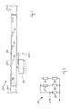
- FIG. 1 shows an elongated, provided with the reference numeral 100 light band system.
- This consists initially of an elongated support assembly 101 consisting of several, successively arranged support rails 102, which are arranged, for example, by means not shown mounting elements directly on a ceiling or suspended from a ceiling.
- These support rails 102 are preferably connected to one another in an elongated arrangement and serve as central support elements for the entire arrangement 100.
- the support rails 102 serve to hold the individual illuminant units described below in more detail and the components for powering these units.
- mounting rails 102 are U-shaped in cross-section and open at the bottom, so that from the bottom of the corresponding receiving space of the support rails 102 is accessible.
- FIG. 1 provided solution that not every bulb unit 50 has its own operating device, but instead several units are supplied by a common operating device 20 centrally.
- subgroups of lighting unit 50 are provided for this purpose, wherein an operating device 20 per support rail 102 is provided. Only this operating device 20 is connected to the - not shown - power supply lines to which the general mains voltage is applied. On the output side of the operating device 20, however, extends a further power supply circuit 25 to which a suitable for the light-emitting device 50 supply current is already applied.
- eachmaschineticiansbuchse 30 of the output circuit 25 allows the connection of a lighting unit 50, which is then supplied by the operating device 20 with power.
- the cost of implementing the illustrated lighting system 100 is correspondingly lower because the number of required equipment can be significantly reduced.
- the concept according to the invention is based on the idea of evaluating the electrical properties of an identification circuit and, based thereon, of identifying the connected lighting unit 50.
- This generally designated by the reference numeral 10 circuit has two input-side terminals and a plurality of parallel resistors R1, R2 and R3.
- R1, R2 and R3 As is known from the prior art, it is provided to characterize the lighting unit by the height of a resistor, but now not a single resistor is used, but the total resistance of the identification circuit 10 is used. It is provided here that at least some of the resistors R1 to R3 are only added to the identification circuit if necessary. In the illustrated embodiment, it is the two resistors R2 and R3.
- these two resistors R2, R3 are each assigned a switching element S1 or S2, by which the corresponding branch in which the resistor R2, R3 is arranged, can be opened or closed.
- switching elements S1 and S2 thus results in a parallel circuit consisting exclusively of the permanently connected resistor R1 or a combination of the resistor R1 with one or two of the further resistors R2 and R3.
- the peculiarity of the solution according to the invention consists in the fact that the resistor (s) R1 to R3 of the identification circuit 10 are not part of the replaceable lamp unit, as hitherto usual, but instead all the components of this circuit arrangement are permanently arranged on or in the mounting rail 101 and fixedly coupled to the operating device 20. That is, it is not necessary to additionally connect the operating device 20 to the lighting unit 50 as before to read an identification resistor.
- the illuminant units 50 will now be able to cooperate with the circuitry including the identification circuit 10 when placed on the mounting rail 101 such that the resistors R2 and R3 are exposed to the identification circuit in a manner characterizing the illuminant unit 50 10 are added.
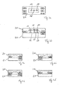
- a conceivable variant for this is in the FIGS. 3a and 3b shown.
- FIG. 3a shows schematically in plan the coupling region of the support rail 102, on which a lighting unit 50 can be arranged.
- corresponding connections 15 to 17 are provided centrally for connection to the power supply lines of the output circuit 25 and possibly to ground the connected lighting unit 50.
- a circuit board 20 is now arranged, on which the above-mentioned identification circuit 10 is formed.
- the corresponding interconnects of this circuit are not shown for reasons of clarity.
- the terminals of the identification circuit and the resistors R1 to R3 are shown with the associated switching elements S1 and S2. As mentioned, these elements via the printed conductors, not shown, to the circuit arrangement, as shown in FIG. 2 is shown connected.
- the switching elements S1 and S2 which are activated or deactivated by the lighting unit 50 in a corresponding manner, designed such that a non-contact interaction takes place.
- the switching elements S1 and S2 are formed by reed contacts, that is to say elements which interact with magnetic elements.
- these reed contacts S1 and S2 are arranged on the board 20, that they are in close proximity to the arranged on the support rail 102 lamp unit 50.
- the lighting unit 50 or its coupling element 51 initially has corresponding contacting elements 55 to 57, which interact with the contacts or sockets 15 to 17 of the connection region.
- the light-emitting device 50 characterizing magnets are provided, which cooperate with the reed contacts S1 and S2.
- a permanent magnet M2 is arranged in the region of the lamp unit 50, which is located immediately after mounting on the support rail 102 in the vicinity of the reed contact S2, which cooperates in the mounted state with the reed contact S2.
- the resistor R3 is automatically added to the identification circuit 10 and the circuit 10 has a total resistance corresponding to a parallel connection of the resistors R1 and R3.
- the operating device can then identify the lighting unit 50 and output a supply current of suitable height.
- resistors R2 and R3 may be added to the circuit 10 in four different ways in this approach. These variants are schematic in the FIGS. 4a to 4d shown, where FIG. 4a the in FIG. 3b corresponds to the variant shown. In the variant according to FIG. 4b on the other hand, only the resistor R2 is connected via the reed contact S1 and the magnet M1, whereas in the variant of FIG Figures 4c and 4d both or none of the resistors R2 and R3 are added. In all these four variants results in a different total resistance for the identification circuit 10, so that in this embodiment, four different light-emitting device 50 can be identified.
- resistors which can optionally be added to the identification circuit, as well as their switching elements S1 and S2 otherwise.
- the resistors would also be a parallel connection between the switching element and the associated resistor conceivable, in which case the corresponding resistor is bypassed, so that it is effectively no longer part of the identification circuit.
- the resistors should be arranged serially, and in principle more complex circuit arrangements would be conceivable.
- FIG. 1 illustrated embodiment does not take place at each contacting possibility of a single support rail corresponding identification of the connected lighting unit.
- a corresponding circuit arrangement which cooperates in the manner according to the invention with the light-emitting unit, is provided. Only this lighting unit is then identified by the operating device and the output supply current is adjusted to this identified unit. This is acceptable, since ideally identical illuminant units should in each case be arranged on a mounting rail in order to be able to achieve a uniform light output over a greater length in the illustrated exemplary embodiment.
- inventive concept could of course be used not only in the illustrated embodiment of an elongated lighting system.
- concept could also be realized in individual luminaires, which have one or more releasably securable lighting modules, which are arranged on a support element of the luminaire.
- Such a procedure has proven itself, as this single modules, where defects in the bulbs occur, can be changed easily.
- the advantage is achieved that the luminaire still requires only a single operating device and, in spite of all, in a simple manner automatically provides a suitable supply current for the luminous-element units.
Landscapes
- Circuit Arrangement For Electric Light Sources In General (AREA)
- Fastening Of Light Sources Or Lamp Holders (AREA)
Abstract
Bei einer Beleuchtungsanordnung mit Leuchtmitteln sowie einem Betriebsgerät (20) zum Bereitstellen eines Versorgungsstroms für die Leuchtmittel sind die Leuchtmittel Bestandteil einer lösbar mit einer Halterung (102) der Anordnung verbindbaren Leuchtmittel-Einheit (50), wobei das Betriebsgerät (20) dazu ausgebildet ist, abhängig von einer die Leuchtmittel-Einheit (50) charakterisierenden Eigenschaft eines Identifizierungsstromkreises (10) einen geeigneten Versorgungsstrom zur Verfügung zu stellen. Der Identifizierungsstromkreis (10) ist Bestandteil einer Schaltungsanordnung mit mehreren elektrischen Elementen (R1, R2, R3), von denen zumindest ein Teil wahlweise dem Identifizierungsstromkreis (10) hinzugefügt werden kann, wobei die Leuchtmittel-Einheit (50) mit der Schaltungsanordnung derart zusammenwirkt, dass in einem an der Halterung (102) der Beleuchtungsanordnung angeordneten Zustand der Leuchtmittel-Einheit (50) eine für die Leuchtmittel-Einheit (50) charakteristische Kombination der elektrischen Elemente (R1, R2, R3) Bestandteil des Identifizierungsstromkreises (10) ist.In a lighting arrangement with luminous means and an operating device (20) for providing a supply current for the lighting means, the lighting means are part of a light-emitting device (50) which can be detachably connected to a holder (102) of the arrangement, the operating device (20) being designed to depending on a characteristic of the lighting unit (50) characteristic of an identification circuit (10) to provide a suitable supply current. The identification circuit (10) is part of a circuit arrangement with a plurality of electrical elements (R1, R2, R3), of which at least one part can optionally be added to the identification circuit (10), the lighting unit (50) interacting with the circuit arrangement in such a way that in that a state of the lighting unit (50) arranged on the holder (102) of the lighting arrangement is a combination of the electrical elements (R1, R2, R3) characteristic of the lighting unit (50) forming part of the identification circuit (10).
Description
Die vorliegende Erfindung betrifft eine Beleuchtungsanordnung gemäß dem Oberbegriff des Anspruchs 1, welche Leuchtmittel sowie ein Betriebsgerät aufweist, wobei das Betriebsgerät einen für die Leuchtmittel geeigneten Versorgungsstrom bereitstellt. Die Leuchtmittel sind dabei Bestandteil einer lösbar mit einer Halterung der Beleuchtungsanordnung verbindbaren Leuchtmittel-Einheit, wobei das Betriebsgerät abhängig von der Leuchtmittel-Einheit den Versorgungsstrom einstellt.The present invention relates to a lighting arrangement according to the preamble of
Im Vergleich zu klassischen Leuchtmitteln wie Glühbirnen oder Leuchtstofflampen erlauben Leuchtmittel auf LED-Basis einen flexibleren Einsatz in der Beleuchtungstechnologie. Während in der Vergangenheit Leuchten lediglich mit einem bestimmten, auf die Leuchte abgestimmten Leuchtmittel - beispielsweise einer Leuchtstofflampe einer bestimmten Größe und Leistungsklasse - bestückt werden konnten, kommen nunmehr in Beleuchtungsanordnungen oftmals auswechselbare Leuchtmittel-Einheiten auf LED-Basis zum Einsatz, welche allerdings einen speziell angepassten Versorgungsstrom benötigen. Grund hierfür ist, dass bspw. zum Erzielen einer einheitlichen gleichmäßigen Lichtabgabe die den LEDs zur Verfügung gestellten Ströme speziell angepasst werden müssen. Da die LEDs selbst allerdings während ihrer Herstellung gewissen Schwankungen unterworfen sind, ergibt sich bspw. für ein LED-Modul nicht grundsätzlich ein identischer erforderlicher Versorgungsstrom bzw. eine identische Versorgungsspannung. Dies wiederum bedeutet, dass die Betriebsgeräte zum Bereitstellen eines entsprechenden Versorgungsstroms für derartige LED-Module in der Lage sein müssen, zumindest innerhalb einer gewissen Bandbreite diesen Strom zu variieren.Compared to traditional bulbs such as light bulbs or fluorescent lamps, LED-based bulbs allow a more flexible use in lighting technology. While in the past luminaires could only be equipped with a specific illuminant, for example a fluorescent lamp of a certain size and power class, replaceable LED-based illuminant units, which, however, have a specially adapted luminaire, are often used in lighting arrangements Need supply current. The reason for this is that, for example, to achieve a uniform, uniform light output, the currents provided to the LEDs must be specially adapted. However, since the LEDs themselves are subject to certain fluctuations during their production, for example, an identical required supply current or an identical supply voltage does not generally result for an LED module. This in turn means that the operating devices for providing a corresponding supply current for such LED modules must be able to vary this current, at least within a certain bandwidth.
Es ist allerdings nicht nur erforderlich, dass das Betriebsgerät in der Lage ist, variabel einen Versorgungsstrom zur Verfügung zu stellen, sondern auch, dass das Betriebsgerät selbst weiß, welche Anforderungen an den Versorgungsstrom und die Versorgungsspannung bestehen.However, it is not only necessary that the operating device is able to variably supply a supply current, but also that the operating device itself knows what requirements exist for the supply current and the supply voltage.
Eine erste Möglichkeit, dieses Problem zu lösen, besteht in einer manuellen Vorgehensweise. In diesem Fall wird also das Betriebsgerät vor Inbetriebnahme der Leuchte entsprechend programmiert oder parametrisiert. Dies bedeutet allerdings, dass während des späteren Betriebs der Versorgungsstrom nicht mehr durch das Betriebsgerät verändert wird und dementsprechend ein Wechsel bspw. eines defekten LED-Moduls nur dann erfolgen kann, wenn das neue Modul hinsichtlich des Versorgungsstroms identische Anforderungen hat. Ein Wechsel hingegen, bspw. auf ein Modul mit modernen LEDs, der einen anderen Versorgungsstrom benötigen, ist in diesem Fall jedoch nicht möglich.A first way to solve this problem is to use a manual approach. In this case, the operating device is accordingly programmed or parameterized before the luminaire is put into operation. However, this means that during the later operation of the supply current is no longer changed by the operating device and accordingly a change eg. A defective LED module can only be done when the new module in terms of Supply current has identical requirements. However, a change, for example, on a module with modern LEDs, which require a different supply current, is not possible in this case.
Eine alternative Vorgehensweise, die ebenfalls aus dem Stand der Technik bekannt ist, sieht deshalb vor, das austauschbare Leuchtmittel-Modul mit einem Identifizierungselement zu versehen. Dieses wird in der Regel durch einen Widerstand gebildet, der durch seinen Widerstandswert das Modul bzw. den von dem Modul benötigten Versorgungsstrom charakterisiert. Mittels spezieller Anschlüsse wird dann dieser Widerstand, der nicht Bestandteil des eigentlichen Stromkreises mit den Leuchtmitteln ist, mit dem Betriebsgerät gekoppelt und dieses kann nach dem Identifizieren des Widerstandswerts den Versorgungsstrom für die Leuchtmittel entsprechend anpassen.An alternative approach, which is also known from the prior art, therefore provides for providing the replaceable lamp module with an identification element. This is usually formed by a resistor which characterizes by its resistance value the module or the supply current required by the module. By means of special connections, this resistor, which is not part of the actual circuit with the lighting means, is then coupled to the operating device and, after the resistance value has been identified, it can adapt the supply current for the lighting devices accordingly.
Diese aus dem Stand der Technik bekannte Vorgehensweise, durch die ein automatisches Anpassen des Versorgungsstroms sichergestellt werden kann, kommt zwar vielfach zum Einsatz, allerdings ist in diesem Fall erforderlich, dass das Leuchtmittel-Modul neben den Anschlüssen für die Stromversorgung zusätzliche Anschlüsse aufweist, über die ein entsprechendes Verbinden des Identifizierungswiderstands mit dem Betriebsgerät ermöglicht wird. Dies führt nicht nur zu einer komplexeren Ausgestaltung des Leuchtmittel-Moduls, sondern auch zu einem erhöhten Aufwand beim Anordnen bzw. Montieren des Moduls an der Beleuchtungsanordnung.Although this procedure known from the prior art, by means of which an automatic adjustment of the supply current can be ensured, is frequently used, in this case it is necessary for the lighting module to have, in addition to the connections for the power supply, additional connections via which a corresponding connection of the identification resistor with the operating device is made possible. This not only leads to a more complex design of the lamp module, but also to an increased effort when arranging or mounting the module to the lighting arrangement.
Der vorliegenden Erfindung liegt deshalb die Aufgabenstellung zugrunde, eine neuartige Lösung anzubieten, welche nach wie vor gewährleistet, dass das Versorgungsgerät automatisch einen auf die Bedürfnisse des Leuchtmittel-Moduls abgestimmten Versorgungsstrom zur Verfügung stellt, andererseits jedoch zu einer vereinfachten Ausgestaltung des Leuchtmittel-Moduls führt.The present invention is therefore based on the object to offer a novel solution, which still ensures that the supply unit automatically provides a tuned to the needs of the lamp module supply current, on the other hand, however, leads to a simplified design of the lamp module.
Die Aufgabe wird durch eine Beleuchtungsanordnung, welche die Merkmale des Anspruchs 1 aufweist, gelöst. Vorteilhafte Weiterbildungen der Erfindung sind Gegenstand der abhängigen Ansprüche.The object is achieved by a lighting arrangement having the features of
Die erfindungsgemäße Lösung beruht wiederum auf dem Gedanken, die Leuchtmittel-Einheit bzw. den von der Leuchtmittel-Einheit benötigten Versorgungsstrom durch mindestens ein elektrisches Bauteil zu charakterisieren, welches mit dem Betriebsgerät gekoppelt ist und durch dieses identifiziert wird. Im Gegensatz zu bislang bekannten Lösungen, bei denen das elektrische Element Bestandteil der auswechselbaren Leuchtmittel-Einheit war, ist nunmehr allerdings vorgesehen, dass das elektrische Element Bestandteil eines Identifizierungsstromkreises ist, der nicht Teil der Leuchtmittel-Einheit ist. Stattdessen ist der Identifizierungsstromkreis mit dem Betriebsgerät verbunden und Bestandteil einer Schaltungsanordnung mit mehreren elektrischen Elementen, die wahlweise dem Identifizierungsstromkreis hinzugefügt werden können. Die auswechselbare Leuchtmittel-Einheit wirkt dabei mit der Schaltungsanordnung derart zusammen, dass in einem an der Halterung der Beleuchtungseinheit angeordneten Zustand der Leuchtmittel-Einheit eine für die Leuchtmittel-Einheit charakteristische Kombination der elektrischen Elemente dem Identifizierungsstromkreis hinzugefügt wird.The solution according to the invention is again based on the idea of characterizing the lighting unit or the supply current required by the lighting unit by at least one electrical component which is coupled to the operating unit and identified by the latter. In contrast to previously known solutions, in which the electrical element is part of the interchangeable Lamp unit was, it is now provided, however, that the electrical element is part of an identification circuit, which is not part of the lighting unit. Instead, the identification circuit is connected to the operating device and part of a circuit arrangement with a plurality of electrical elements, which can optionally be added to the identification circuit. The replaceable lamp unit interacts with the circuit arrangement in such a way that in a state of the lamp unit arranged on the holder of the lighting unit, a combination of the electrical elements characteristic of the lamp unit is added to the identification circuit.
Erfindungsgemäß wird also eine Beleuchtungsanordnung mit Leuchtmitteln sowie einem Betriebsgerät zum Bereitstellen eines Versorgungsstroms für die Leuchtmittel vorgeschlagen, wobei die Leuchtmittel Bestandteil einer lösbar mit einer Halterung der Beleuchtungsanordnung verbindbaren Leuchtmittel-Einheit sind und wobei das Betriebsgerät dazu ausgebildet ist, abhängig von einer die Leuchtmittel-Einheit charakterisierenden Eigenschaft eines Identifizierungsstromkreises einen geeigneten Versorgungsstrom zur Verfügung zu stellen. Die erfindungsgemäße Beleuchtungsanordnung ist dabei dadurch gekennzeichnet, dass der Identifizierungsstromkreis Bestandteil einer Schaltungsanordnung mit mehreren elektrischen Elementen ist, welche wahlweise dem Identifizierungsstromkreis hinzugefügt werden können, wobei die Leuchtmittel-Einheit mit der Schaltungsanordnung derart zusammenwirkt, dass in einem an der Halterung der Beleuchtungsanordnung angeordneten Zustand der Leuchtmittel-Einheit eine für die Leuchtmittel-Einheit charakteristische Kombination der elektrischen Elemente Bestandteil des Identifizierungsstromkreises ist.According to the invention, therefore, a lighting arrangement with lighting means and an operating device for providing a supply current for the lighting means is proposed, wherein the lighting means are part of a releasably connectable to a holder of the lighting arrangement lamp unit and wherein the operating device is designed, depending on a the lighting unit characterizing feature of an identification circuit to provide a suitable supply current. The lighting arrangement according to the invention is characterized in that the identification circuit is part of a circuit arrangement with a plurality of electrical elements, which can optionally be added to the identification circuit, wherein the lighting unit cooperates with the circuit arrangement such that in a arranged on the holder of the lighting arrangement state of Lamp unit is a characteristic of the lighting unit combination of electrical elements part of the identification circuit.
Die die Leuchtmittel-Einheit identifizierenden Elemente, bei denen es sich vorzugsweise wiederum um ein oder mehrere Widerstände handelt, sind nun also unmittelbar Bestandteil der Beleuchtungsanordnung, nicht jedoch Bestandteil der auswechselbaren Leuchtmittel-Einheit. Die diese elektrischen Elemente beinhaltende Schaltungsanordnung erlaubt jedoch, dass durch die Leuchtmittel-Einheit im montierten Zustand wahlweise einzelne der elektrischen Elemente dem Identifizierungsstromkreis hinzugefügt werden können. Hierdurch wird vermieden, dass neben den Anschlüssen für die Stromversorgung die Leuchtmittel-Einheit zusätzlich elektrisch mit dem Betriebsgerät verbunden werden muss. Ferner können die einzelnen elektrischen Elemente besser abgestimmt auf das Betriebsgerät ausgewählt werden, so dass ggf. auch eine zuverlässigere und exaktere Identifizierung der Leuchtmittel-Einheit ermöglicht wird.The elements identifying the lamp unit, which are in turn preferably one or more resistors, are therefore now an integral part of the lighting arrangement, but not part of the exchangeable lamp unit. The circuitry comprising these electrical elements, however, allows either individual ones of the electrical elements to be added to the identification circuit by the lighting unit in the mounted state. This avoids that in addition to the connections for the power supply, the lamp unit must also be electrically connected to the operating device. Furthermore, the individual electrical elements can be selected better matched to the operating device, so that, if necessary, a more reliable and accurate identification of the lighting unit is made possible.
Das wahlweise Hinzufügen der elektrischen Elemente zu dem Identifizierungsstromkreis erfolgt vorzugsweise dadurch, dass jedem der Elemente jeweils ein Schaltelement zugeordnet ist, durch welches das entsprechende Element dem Stromkreis hinzugefügt oder von diesem getrennt werden kann. In einfacher Weise sind hierbei bspw. alle einzelnen elektrischen Elemente parallel zueinander verschaltet, wobei der jeweilige Zweig dann wahlweise durch ein Schaltelement unterbrochen bzw. geschlossen werden kann. Alternativ hierzu könnte durch ein entsprechendes Schaltelement allerdings auch das elektrische Element kurzgeschlossen bzw. überbrückt werden, so dass es wiederum effektiv gesehen kein Bestandteil des Identifizierungsstromkreises ist.The optional addition of the electrical elements to the identification circuit is preferably carried out by each of the elements is assigned in each case a switching element through which the corresponding element can be added to the circuit or separated from it. In a simple way, in this case, for example, all the individual electrical elements are connected in parallel to one another, wherein the respective branch can then optionally be interrupted or closed by a switching element. As an alternative to this, however, the electrical element could also be short-circuited or bridged by a corresponding switching element, so that, in turn, it is effectively not part of the identification circuit.
Vorzugsweise ist dabei vorgesehen, dass das Zusammenwirken zwischen Leuchtmittel-Einheit und Schaltungsanordnung derart erfolgt, dass die Leuchtmittel-Einheit berührungslos die entsprechenden Schaltelemente betätigt. Dies könnte bspw. dadurch erfolgen, dass die Leuchtmittel-Einheit abgestimmt auf die Positionen der entsprechenden Schaltelemente magnetische Elemente aufweist und die Schaltelemente durch mit diesen Magneten zusammenwirkende Reed-Kontakte gebildet sind. Beim Einsetzen bzw. Montieren der Leuchtmittel-Einheit an dem Träger der Beleuchtungsanordnung werden dann automatisch die entsprechenden Magnete in unmittelbarer Nähe der entsprechenden Reed-Kontakte positioniert, so dass dann die zugehörigen elektrischen Elemente entsprechend dem Identifizierungsstromkreis hinzugefügt werden.Preferably, it is provided that the interaction between the lamp unit and the circuit arrangement takes place in such a way that the lamp unit operates contactlessly the corresponding switching elements. This could, for example, be effected by the lighting unit having magnetic elements matched to the positions of the corresponding switching elements and the switching elements being formed by reed contacts cooperating with these magnets. When inserting or mounting the lamp unit to the support of the lighting arrangement, the corresponding magnets are then automatically positioned in the immediate vicinity of the corresponding reed contacts, so that then the associated electrical elements are added according to the identification circuit.
Alternativ zu der oben beschriebenen berührungslosen Variante wäre allerdings auch eine mechanische Alternative denkbar, bei der an der Leuchtmittel-Einheit entsprechende Vorsprünge oder Stifte ausgebildet sind, welche dann wahlweise das entsprechende Schaltelement mechanisch betätigen.As an alternative to the non-contact variant described above, however, a mechanical alternative would also be conceivable in which corresponding protrusions or pins are formed on the lighting unit, which then optionally actuate the corresponding switching element mechanically.
Im Rahmen einer größeren Beleuchtungsanordnung kann vorgesehen sein, dass durch das Betriebsgerät mehrere auswechselbare Leuchtmittel-Einheiten mit Strom versorgt werden. In diesem Fall sollte es sich vorzugsweise jeweils um gleichartige Leuchtmittel-Einheiten handeln, die jeweils einen identischen Versorgungsstrom benötigen. Eine Identifizierung jeder einzelnen Leuchtmittel-Einheit ist in diesem Fall dann nicht erforderlich. Stattdessen ist vorzugsweise vorgesehen, dass lediglich für eine der Leuchtmittel-Einheiten eine entsprechende Montageposition vorgesehen ist, in der das erfindungsgemäße Zusammenwirken mit einer Schaltungsanordnung, die den Identifizierungsstromkreis beinhaltet, vorgesehen ist. D.h., diese spezielle Leuchtmittel-Einheit dient dazu, alle Leuchtmittel-Einheiten zu identifizieren und die Stromversorgung für diese sicherzustellen.As part of a larger lighting arrangement can be provided that are supplied by the operating device several replaceable lamp units with power. In this case, it should preferably be in each case to similar lighting units, each requiring an identical supply current. An identification of each individual lighting unit is then not required in this case. Instead, it is preferably provided that only for one of the lamp units, a corresponding mounting position is provided, in which the inventive cooperation with a circuit arrangement that includes the identification circuit, is provided. That is, this special Bulb unit is used to identify and ensure power supply to all bulbs.
Nachfolgend soll die Erfindung anhand der beiliegenden Zeichnung näher erläutert werden. Es zeigen:
Figur 1- eine Beleuchtungsanordnung mit einem Betriebsgerät sowie mehreren von dem Betriebsgerät versorgten auswechselbaren Leuchtmittel-Einheiten;
Figur 2- eine einfache Variante einer Schaltungsanordnung, welche einen Identifizierungsstromkreis beinhaltet;
- Figuren 3a und 3b
- ein Ausführungsbeispiel einer erfindungsgemäß mit der Schaltungsanordnung zusammenwirkenden Leuchtmittel-Einheit und
- Figuren 4a bis 4d
- schematische Darstellungen zur Verdeutlichung der Funktionsweise des Ausführungsbeispiels von
Figur 3 .
- FIG. 1
- a lighting arrangement with an operating device and a plurality of replaceable lamp units supplied by the operating device;
- FIG. 2
- a simple variant of a circuit arrangement, which includes an identification circuit;
- FIGS. 3a and 3b
- An embodiment of an inventively cooperating with the circuit arrangement lamp unit and
- FIGS. 4a to 4d
- schematic representations to illustrate the operation of the embodiment of
FIG. 3 ,
Im vorliegenden Fall ist lediglich schematisch dargestellt, in welcher Weise die Stromversorgung der auswechselbaren Leuchtmittel-Einheiten 50 erfolgt. Bislang war es hierzu bekannt, dass innerhalb der Trägeranordnung 101 Stromversorgungsleitungen verlaufen, welche entweder an beliebiger Stelle oder an bestimmten vorgegebenen Postionen durch die auswechselbar anzuordnenden Leuchtmittel-Einheiten 50 kontaktiert werden konnten. Diese Stromversorgungsleitungen stellten dabei die normale Netzversorgungsspannung zur Verfügung, welche dann von entsprechenden Betriebsgeräten der einzelnen Leuchtmittel-Einheiten in geeigneter Weise umgesetzt werden mussten. Bei dieser bislang bekannten Lösung war es also erforderlich, dass jede Leuchtmittel-Einheit 50 ein eigenes Betriebsgerät, bspw. einen Konverter zum Umsetzen der allgemeinen Netzversorgungsspannung in einen für die Leuchtmittel geeigneten Versorgungsstrom aufwies.In the present case, it is only shown schematically in which way the power supply of the
Demgegenüber ist bei der in
Damit sichergestellt ist, dass die Leuchtmittel der einzelnen Leuchtmittel-Einheiten 50 tatsächlich mit einem geeigneten Versorgungsstrom versorgt werden, muss - wie eingangs geschildert - sichergestellt werden, dass das Betriebsgerät 20 Kenntnis vom Typ der angeschlossenen Leuchtmittel-Einheiten 50 hat bzw. weiß, was für ein Versorgungsstrom tatsächlich benötigt wird. Mit der nachfolgend näher beschriebenen Erfindung wird dieses Problem gelöst.To ensure that the light sources of the
Grundsätzlich beruht das erfindungsgemäße Konzept auf dem Gedanken, die elektrischen Eigenschaften eines Identifizierungsstromkreises zu bewerten und darauf basierend die angeschlossene Leuchtmittel-Einheit 50 identifizieren. Schematisch ist ein entsprechender Identifizierungsstromkreis in
Die Besonderheit der erfindungsgemäßen Lösung besteht nunmehr darin, dass der bzw. die Widerstände R1 bis R3 des Identifizierungsstromkreises 10 nicht - wie bislang üblich - Bestandteil der auswechselbaren Leuchtmittel-Einheit sind, sondern stattdessen sämtliche Komponenten dieser Schaltungsanordnung dauerhaft an bzw. in der Tragschiene 101 angeordnet und fest mit dem Betriebsgerät 20 gekoppelt sind. D.h., es ist nicht wie bislang erforderlich, das Betriebsgerät 20 zusätzlich mit der Leuchtmittel-Einheit 50 zu verbinden, um einen Identifizierungswiderstand auszulesen.The peculiarity of the solution according to the invention consists in the fact that the resistor (s) R1 to R3 of the
Allerdings werden nunmehr die Leuchtmittel-Einheiten 50 in die Lage versetzt, beim Anordnen an der Tragschiene 101 derart mit der Schaltungsanordnung, welche den Identifizierungsstromkreis 10 beinhaltet, zusammenzuwirken, dass die Widerstände R2 und R3 in einer für die Leuchtmittel-Einheit 50 charakterisierenden Weise dem Identifizierungsstromkreis 10 hinzugefügt werden. Eine denkbare Variante hierzu ist in den
Gemäß einer bevorzugten Ausführungsform der Erfindung ist nunmehr vorgesehen, dass die Schaltelemente S1 und S2, welche durch die Leuchtmittel-Einheit 50 in entsprechender Weise aktiviert bzw. deaktiviert werden, derart ausgeführt, dass ein berührungsloses Zusammenwirken erfolgt. Dies kann in besonders bevorzugter Weise dadurch realisiert werden, dass die Schaltelemente S1 und S2 durch Reed-Kontakte, also Elemente gebildet sind, welche mit magnetischen Elementen zusammenwirken. Wie der seitlichen Ansicht von
Die Leuchtmittel-Einheit 50 bzw. deren Kopplungselement 51 weist hierbei zunächst entsprechende Kontaktierungselemente 55 bis 57 auf, welche mit den Kontakten bzw. Buchsen 15 bis 17 des Anschlussbereichs zusammenwirken. Zusätzlich sind allerdings die Leuchtmittel-Einheit 50 charakterisierende Magnete vorgesehen, welche mit den Reed-Kontakten S1 und S2 zusammenwirken. Im dargestellten Ausführungsbeispiel ist in demjenigen Bereich der Leuchtmittel-Einheit 50, der sich nach Montage an der Tragschiene 102 unmittelbar in der Nähe des Reed-Kontaktes S2 befindet, ein Permanentmagnet M2 angeordnet, der im montierten Zustand mit dem Reed-Kontakt S2 zusammenwirkt. D.h., beim Ansetzen der Leuchtmittel-Einheit 50 an die Tragschiene 102 wird automatisch der Widerstand R3 dem Identifizierungsstromkreis 10 hinzugefügt und der Stromkreis 10 weist einen Gesamtwiderstand auf, der einer Parallelschaltung der Widerstände R1 und R3 entspricht. Durch Bewertung des Stromflusses, der sich in dem hieraus resultierenden Identifizierungsstromkreis 10 ergibt, kann dann also das Betriebsgerät die Leuchtmittel-Einheit 50 identifizieren und einen Versorgungsstrom geeigneter Höhe ausgeben.In this case, the
Offensichtlich können bei dieser Vorgehensweise die Widerstände R2 und R3 in vier verschiedenen Varianten dem Stromkreis 10 hinzugefügt werden. Diese Varianten sind schematisch in den
Selbstverständlich wäre es denkbar, die Widerstände, die wahlweise dem Identifizierungsstromkreis hinzugefügt werden können, sowie deren Schaltelemente S1 und S2 anderweitig anzuordnen. Bspw. wäre auch eine Parallelschaltung zwischen Schaltelement und dem zugehörigen Widerstand denkbar, wobei dann der entsprechende Widerstand überbrückt wird, so dass er effektiv nicht mehr Bestandteil des Identifizierungsstromkreises ist. In diesem Fall sollten allerdings dann die Widerstände seriell angeordnet werden, wobei grundsätzlich auch komplexere Schaltungsanordnungen denkbar wären.Of course, it would be conceivable to arrange the resistors, which can optionally be added to the identification circuit, as well as their switching elements S1 and S2 otherwise. For example. would also be a parallel connection between the switching element and the associated resistor conceivable, in which case the corresponding resistor is bypassed, so that it is effectively no longer part of the identification circuit. In this case, however, then the resistors should be arranged serially, and in principle more complex circuit arrangements would be conceivable.
Ferner wäre es ebenfalls denkbar, anstelle der Widerstände andere elektrische Elemente zu verwenden, welche zu einer Veränderung der gesamten Charakteristik des Identifizierungsstromkreises beitragen. Denkbar wäre also bspw. auch der Einsatz von Induktivitäten oder dergleichen, wobei allerdings hier dann die Auswertung aufwendiger wäre, so dass die dargestellte Variante sicherlich zu bevorzugen ist.Furthermore, it would also be conceivable to use other electrical elements instead of the resistors, which contribute to a change in the overall characteristic of the identification circuit. Also conceivable would be, for example, the use of inductors or the like, although here then the evaluation would be more expensive, so that the illustrated variant is certainly preferable.
Schließlich muss auch nicht zwingend ein berührungsloses Zusammenwirken zwischen den Schaltelementen und der anzuschließenden Leuchtmittel-Einheit vorgesehen sein. Denkbar wäre auch, dass die Schaltelemente mechanisch durch die Leuchtmittel-Einheit betätigt werden. In diesem Fall müssten dann an der Außenseite der Leuchtmittel-Einheit 50 entsprechende Vorsprünge oder Stifte vorgesehen sein, durch welche die Schaltelemente wahlweise betätigt werden können.Finally, it is not absolutely necessary to provide a contactless interaction between the switching elements and the lamp unit to be connected. It would also be conceivable that the switching elements are mechanically actuated by the lamp unit. In this case, corresponding protrusions or pins would then have to be provided on the outside of the
Bei dem in
Schließlich ist auch darauf hinzuweisen, dass das erfindungsgemäße Konzept selbstverständlich nicht nur bei dem dargestellten Ausführungsbeispiel eines länglichen Lichtbandsystems zum Einsatz kommen könnte. In gleicher Weise könnte das Konzept auch bei Einzelleuchten realisiert werden, welche ein oder mehrere lösbar befestigbare Leuchtmodule aufweisen, die an einem Trägerelement der Leuchte angeordnet werden. Eine derartige Vorgehensweise hat sich bewährt, da hierdurch einzelne Module, bei denen Defekte in den Leuchtmitteln auftreten, in einfacher Weise gewechselt werden können. Auch in diesem Fall wird jedoch der Vorteil erzielt, dass die Leuchte nach wie vor lediglich ein einziges Betriebsgerät benötigt und trotz allem in einfacher Weise automatisch ein geeigneter Versorgungsstrom für die Leuchtmittel-Einheiten zur Verfügung gestellt wird.Finally, it should also be noted that the inventive concept could of course be used not only in the illustrated embodiment of an elongated lighting system. In the same way, the concept could also be realized in individual luminaires, which have one or more releasably securable lighting modules, which are arranged on a support element of the luminaire. Such a procedure has proven itself, as this single modules, where defects in the bulbs occur, can be changed easily. In this case too, however, the advantage is achieved that the luminaire still requires only a single operating device and, in spite of all, in a simple manner automatically provides a suitable supply current for the luminous-element units.
Claims (10)
wobei die Leuchtmittel Bestandteil einer lösbar mit einer Halterung (102) der Anordnung verbindbaren Leuchtmittel-Einheit (50) sind,
und wobei das Betriebsgerät (20) dazu ausgebildet ist, abhängig von einer die Leuchtmittel-Einheit (50) charakterisierenden Eigenschaft eines Identifizierungsstromkreises (10) einen geeigneten Versorgungsstrom zur Verfügung zu stellen,
dadurch gekennzeichnet,
dass der Identifizierungsstromkreis (10) Bestandteil einer Schaltungsanordnung mit mehreren elektrischen Elementen (R1, R2, R3) ist, von denen zumindest ein Teil wahlweise dem Identifizierungsstromkreis (10) hinzugefügt werden kann,
wobei die Leuchtmittel-Einheit (50) mit der Schaltungsanordnung derart zusammenwirkt, dass in einem an der Halterung (102) der Beleuchtungsanordnung angeordneten Zustand der Leuchtmittel-Einheit (50) eine für die Leuchtmittel-Einheit (50) charakteristische Kombination der elektrischen Elemente (R1, R2, R3) Bestandteil des Identifizierungsstromkreises (10) ist.Lighting arrangement with lighting means and an operating device (20) for providing a supply current for the lighting means,
the lighting means being part of a light-emitting means unit (50) which can be connected detachably to a holder (102) of the arrangement,
and wherein the operating device (20) is designed to provide a suitable supply current, depending on a property of an identification circuit (10) characterizing the lighting unit (50),
characterized,
in that the identification circuit (10) is part of a circuit arrangement with a plurality of electrical elements (R1, R2, R3), of which at least a part can optionally be added to the identification circuit (10),
wherein the lighting unit (50) cooperates with the circuit arrangement in such a manner that in a state of the lighting unit (50) arranged on the holder (102) of the lighting arrangement, a combination of the electrical elements (R1 , R2, R3) is part of the identification circuit (10).
dadurch gekennzeichnet,
dass den zuschaltbaren elektrischen Elementen (R2, R3) jeweils ein Schaltelement (S1, S2) zugeordnet ist, wobei die Leuchtmittel-Einheit (50) dazu ausgebildet ist, in einem an der Halterung (102) angeordneten Zustand mit den Schaltelementen (S1, S2) zusammenzuwirken.Lighting arrangement according to claim 1,
characterized,
in that the shiftable electrical elements (R2, R3) are each assigned a switching element (S1, S2), wherein the lighting device (50) is designed to be in a state arranged on the mount (102) with the switching elements (S1, S2 ) to cooperate.
dadurch gekennzeichnet,
dass es sich bei den elektrischen Elementen (R1, R2, R3) um Widerstände handelt.Lighting arrangement according to claim 2,
characterized,
that the electrical elements (R1, R2, R3) are resistors.
dadurch gekennzeichnet,
dass die Widerstände (R1, R2, R3) parallel zueinander angeordnet sind, wobei zumindest einigen der Widerstände (R1, R2, R3) jeweils ein Schaltelement (S1, S2) zugeordnet ist, durch welches ein Stromfluss durch den zugehörigen Zweig des Identifizierungsstromkreises (10) wahlweise zugelassen oder unterbrochen wird.Lighting arrangement according to claim 3,
characterized,
in that the resistors (R1, R2, R3) are arranged parallel to one another, wherein at least some of the resistors (R1, R2, R3) are each assigned a switching element (S1, S2), by which a current flow through the associated branch of the identification circuit (10 ) is either allowed or interrupted.
dadurch gekennzeichnet,
dass die Leuchtmittel-Einheit (50) Mittel zum berührungslosen Aktivieren zumindest einiger der Schaltelemente (S1, S2) aufweist.Lighting arrangement according to one of claims 2 to 4,
characterized,
in that the lighting unit (50) has means for non-contact activation of at least some of the switching elements (S1, S2).
dadurch gekennzeichnet,
dass des sich bei den Mitteln zum Aktivieren um Magnete (M1, M2) handelt und die Schaltelemente (S1, S2) durch Reed-Kontakte gebildet sind.Luminaire according to claim 5,
characterized,
in that the means for activating are magnets (M1, M2) and the switching elements (S1, S2) are formed by reed contacts.
dadurch gekennzeichnet,
dass die Leuchtmittel-Einheit (50) Mittel zur mechanischen Betätigung der Schaltelemente (S1, S2) aufweist.Lighting arrangement according to one of claims 2 to 4,
characterized,
in that the lighting unit (50) has means for the mechanical actuation of the switching elements (S1, S2).
dadurch gekennzeichnet,
dass die Halterung (102) für die Leuchtmittel-Einheit (50) Anschlussmittel (30) zur elektrischen Stromversorgung der Leuchtmittel-Einheit (50) aufweist.Lighting arrangement according to one of the preceding claims,
characterized,
that the holder (102) for the lighting means unit (50) comprises connecting means (30) for electrical power supply of the lighting means unit (50).
dadurch gekennzeichnet,
dass das Betriebsgerät (20) ausgangsseitig mit einem Stromversorgungskreis (25) zur Versorgung mehrerer Leuchtmittel-Einheiten (50) verbunden ist.Lighting arrangement according to one of the preceding claims,
characterized,
in that the operating device (20) is connected on the output side to a power supply circuit (25) for supplying a plurality of lamp unit (50).
dadurch gekennzeichnet,
dass lediglich für eine an den Stromversorgungskreis (25) angeschlossene Leuchtmittel-Einheit (50) eine Identifizierung vorgesehen ist.Lighting arrangement according to claim 9,
characterized,
that an identification is provided only for one of the power supply circuit (25) connected to the lighting unit (50).
Applications Claiming Priority (1)
| Application Number | Priority Date | Filing Date | Title |
|---|---|---|---|
| DE202014102007.1U DE202014102007U1 (en) | 2014-04-29 | 2014-04-29 | Lighting arrangement with operating device for providing a suitable supply current |
Publications (2)
| Publication Number | Publication Date |
|---|---|
| EP2941096A2 true EP2941096A2 (en) | 2015-11-04 |
| EP2941096A3 EP2941096A3 (en) | 2015-12-30 |
Family
ID=53002612
Family Applications (1)
| Application Number | Title | Priority Date | Filing Date |
|---|---|---|---|
| EP15165361.5A Withdrawn EP2941096A3 (en) | 2014-04-29 | 2015-04-28 | Lighting assembly with an operating device for providing an appropriate supply current |
Country Status (3)
| Country | Link |
|---|---|
| EP (1) | EP2941096A3 (en) |
| AT (1) | AT15511U1 (en) |
| DE (1) | DE202014102007U1 (en) |
Cited By (2)
| Publication number | Priority date | Publication date | Assignee | Title |
|---|---|---|---|---|
| DE102018118000B3 (en) | 2018-04-23 | 2019-10-17 | Stego-Holding Gmbh | Luminaire, arrangement, in particular door contact switch, circuit board and use |
| USD888314S1 (en) | 2018-04-16 | 2020-06-23 | Stego-Holding Gmbh | LED lamp |
Families Citing this family (1)
| Publication number | Priority date | Publication date | Assignee | Title |
|---|---|---|---|---|
| DE102015219367B4 (en) * | 2015-10-07 | 2022-07-14 | H4X E.U. | LED LIGHT WITH CONTROL CIRCUIT |
Family Cites Families (5)
| Publication number | Priority date | Publication date | Assignee | Title |
|---|---|---|---|---|
| DE19530485A1 (en) * | 1995-08-18 | 1997-02-20 | Patent Treuhand Ges Fuer Elektrische Gluehlampen Mbh | Method and circuit arrangement for operating an electric lamp |
| JP2004012778A (en) * | 2002-06-06 | 2004-01-15 | Toshiba Corp | Projector apparatus, lamp lighting circuit and method for controlling the same |
| DE102008033176A1 (en) * | 2008-07-15 | 2010-01-21 | Automotive Lighting Reutlingen Gmbh | Light source i.e. LED, arrangement manufacturing method for e.g. motor vehicle headlight, involves arranging resistor element directly on circuit carrier, and adjusting resistance value of element as function of characteristics of LED |
| WO2010150158A1 (en) * | 2009-06-26 | 2010-12-29 | Koninklijke Philips Electronics N.V. | Lighting arrangement comprising magnetic coding means |
| DE102009051866A1 (en) * | 2009-11-04 | 2011-05-05 | Automotive Lighting Reutlingen Gmbh | Method for manufacturing light source arrangement for headlight of motor vehicle, involves determining resistance value of resistance element by not-cutting splitting and separation of portions of carrier depending on LED characteristics |
-
2014
- 2014-04-29 DE DE202014102007.1U patent/DE202014102007U1/en not_active Expired - Lifetime
- 2014-05-30 AT ATGM237/2014U patent/AT15511U1/en not_active IP Right Cessation
-
2015
- 2015-04-28 EP EP15165361.5A patent/EP2941096A3/en not_active Withdrawn
Non-Patent Citations (1)
| Title |
|---|
| None |
Cited By (4)
| Publication number | Priority date | Publication date | Assignee | Title |
|---|---|---|---|---|
| USD888314S1 (en) | 2018-04-16 | 2020-06-23 | Stego-Holding Gmbh | LED lamp |
| DE102018118000B3 (en) | 2018-04-23 | 2019-10-17 | Stego-Holding Gmbh | Luminaire, arrangement, in particular door contact switch, circuit board and use |
| WO2019206822A1 (en) | 2018-04-23 | 2019-10-31 | Stego-Holding Gmbh | Luminaire, arrangement, particularly door contact switch, circuit board and use |
| US11215348B2 (en) | 2018-04-23 | 2022-01-04 | Stego-Holding Gmbh | Luminaire, arrangement, particularly door contact switch, circuit board and use |
Also Published As
| Publication number | Publication date |
|---|---|
| AT15511U1 (en) | 2017-11-15 |
| DE202014102007U1 (en) | 2015-07-31 |
| EP2941096A3 (en) | 2015-12-30 |
Similar Documents
| Publication | Publication Date | Title |
|---|---|---|
| EP1467056A2 (en) | Garage door operator with lighting unit | |
| EP3114404B1 (en) | Light fixture comprising a carrier element and detachably securable lighting module | |
| EP2941096A2 (en) | Lighting assembly with an operating device for providing an appropriate supply current | |
| AT14509U1 (en) | lighting system | |
| WO2014056977A1 (en) | Printed circuit board for populating with illumination bodies, comprising a variable working window | |
| EP2526337B1 (en) | Device for holding luminous led elements | |
| WO2008104309A1 (en) | Light source for simulating a spot light source, and lamp having such a light source | |
| EP2989696B1 (en) | Support rail for forming a lighting strip system and lighting strip system | |
| EP1790814A1 (en) | Garage door actuator with lighting unit | |
| DE202010006540U1 (en) | Adapter arrangement for operating an electric light on a table | |
| DE202004000449U1 (en) | Electrical strip lighting has unit mounted on wall rails that conduct electrical power to light emitting diodes | |
| DE102019217344A1 (en) | LIGHTING MODULES WITH A CIRCUIT SUPPORT AND LIGHT SOURCES | |
| DE102012103229B4 (en) | Lighting device with an operating and control device and at least one electronically connected LED light source with at least one LED | |
| DE3918699A1 (en) | Adjustable holding device for low-voltage luminaire | |
| DE202013104307U1 (en) | LEDs on PCB strips | |
| EP2829793B1 (en) | Attachment element for luminaire | |
| EP0648970A1 (en) | Pillar-shaped indicator lamp | |
| WO2015007352A1 (en) | Led module | |
| CH710027A2 (en) | Lamp with magnetic fixing | |
| EP3022990A1 (en) | Lighting device | |
| DE102010002053B4 (en) | Arrangement for producing an electrically conductive connection between two components, and circuit arrangement hereby | |
| DE202004009717U1 (en) | Circular electrical light bulb has number of LED elements mounted on a circuit board strip in such a way as to produce uniform output | |
| DE202016101353U1 (en) | Flat wall or ceiling light and luminaire module system for forming such a lamp | |
| EP1229288A2 (en) | Lamp with back-up power supply control | |
| DE3506863A1 (en) | Illuminating device for a fibre optic communicator |
Legal Events
| Date | Code | Title | Description |
|---|---|---|---|
| PUAI | Public reference made under article 153(3) epc to a published international application that has entered the european phase |
Free format text: ORIGINAL CODE: 0009012 |
|
| AK | Designated contracting states |
Kind code of ref document: A2 Designated state(s): AL AT BE BG CH CY CZ DE DK EE ES FI FR GB GR HR HU IE IS IT LI LT LU LV MC MK MT NL NO PL PT RO RS SE SI SK SM TR |
|
| AX | Request for extension of the european patent |
Extension state: BA ME |
|
| PUAL | Search report despatched |
Free format text: ORIGINAL CODE: 0009013 |
|
| AK | Designated contracting states |
Kind code of ref document: A3 Designated state(s): AL AT BE BG CH CY CZ DE DK EE ES FI FR GB GR HR HU IE IS IT LI LT LU LV MC MK MT NL NO PL PT RO RS SE SI SK SM TR |
|
| AX | Request for extension of the european patent |
Extension state: BA ME |
|
| RIC1 | Information provided on ipc code assigned before grant |
Ipc: H05B 33/08 20060101AFI20151124BHEP |
|
| STAA | Information on the status of an ep patent application or granted ep patent |
Free format text: STATUS: THE APPLICATION IS DEEMED TO BE WITHDRAWN |
|
| 18D | Application deemed to be withdrawn |
Effective date: 20160701 |