EP2938837B1 - Gas turbine seal assembly and seal support - Google Patents
Gas turbine seal assembly and seal support Download PDFInfo
- Publication number
- EP2938837B1 EP2938837B1 EP13868215.8A EP13868215A EP2938837B1 EP 2938837 B1 EP2938837 B1 EP 2938837B1 EP 13868215 A EP13868215 A EP 13868215A EP 2938837 B1 EP2938837 B1 EP 2938837B1
- Authority
- EP
- European Patent Office
- Prior art keywords
- assembly
- seal
- module
- radial wall
- cavity
- Prior art date
- Legal status (The legal status is an assumption and is not a legal conclusion. Google has not performed a legal analysis and makes no representation as to the accuracy of the status listed.)
- Active
Links
- 230000000717 retained effect Effects 0.000 claims description 4
- 238000011144 upstream manufacturing Methods 0.000 claims 1
- 239000007789 gas Substances 0.000 description 37
- 238000002485 combustion reaction Methods 0.000 description 5
- 238000007789 sealing Methods 0.000 description 4
- 230000037406 food intake Effects 0.000 description 3
- 238000010438 heat treatment Methods 0.000 description 3
- 239000003570 air Substances 0.000 description 2
- 239000012080 ambient air Substances 0.000 description 2
- 239000000567 combustion gas Substances 0.000 description 2
- 239000000446 fuel Substances 0.000 description 2
- 238000012986 modification Methods 0.000 description 2
- 230000004048 modification Effects 0.000 description 2
- 238000007792 addition Methods 0.000 description 1
- 210000003746 feather Anatomy 0.000 description 1
- 239000012530 fluid Substances 0.000 description 1
- 238000009434 installation Methods 0.000 description 1
- 238000004519 manufacturing process Methods 0.000 description 1
- 239000000463 material Substances 0.000 description 1
- 230000013011 mating Effects 0.000 description 1
- 239000000203 mixture Substances 0.000 description 1
- 230000005855 radiation Effects 0.000 description 1
Images


Classifications
-
- F—MECHANICAL ENGINEERING; LIGHTING; HEATING; WEAPONS; BLASTING
- F01—MACHINES OR ENGINES IN GENERAL; ENGINE PLANTS IN GENERAL; STEAM ENGINES
- F01D—NON-POSITIVE DISPLACEMENT MACHINES OR ENGINES, e.g. STEAM TURBINES
- F01D11/00—Preventing or minimising internal leakage of working-fluid, e.g. between stages
- F01D11/001—Preventing or minimising internal leakage of working-fluid, e.g. between stages for sealing space between stator blade and rotor
-
- F—MECHANICAL ENGINEERING; LIGHTING; HEATING; WEAPONS; BLASTING
- F01—MACHINES OR ENGINES IN GENERAL; ENGINE PLANTS IN GENERAL; STEAM ENGINES
- F01D—NON-POSITIVE DISPLACEMENT MACHINES OR ENGINES, e.g. STEAM TURBINES
- F01D11/00—Preventing or minimising internal leakage of working-fluid, e.g. between stages
- F01D11/005—Sealing means between non relatively rotating elements
-
- F—MECHANICAL ENGINEERING; LIGHTING; HEATING; WEAPONS; BLASTING
- F01—MACHINES OR ENGINES IN GENERAL; ENGINE PLANTS IN GENERAL; STEAM ENGINES
- F01D—NON-POSITIVE DISPLACEMENT MACHINES OR ENGINES, e.g. STEAM TURBINES
- F01D11/00—Preventing or minimising internal leakage of working-fluid, e.g. between stages
- F01D11/003—Preventing or minimising internal leakage of working-fluid, e.g. between stages by packing rings; Mechanical seals
-
- F—MECHANICAL ENGINEERING; LIGHTING; HEATING; WEAPONS; BLASTING
- F01—MACHINES OR ENGINES IN GENERAL; ENGINE PLANTS IN GENERAL; STEAM ENGINES
- F01D—NON-POSITIVE DISPLACEMENT MACHINES OR ENGINES, e.g. STEAM TURBINES
- F01D25/00—Component parts, details, or accessories, not provided for in, or of interest apart from, other groups
- F01D25/24—Casings; Casing parts, e.g. diaphragms, casing fastenings
- F01D25/246—Fastening of diaphragms or stator-rings
-
- F—MECHANICAL ENGINEERING; LIGHTING; HEATING; WEAPONS; BLASTING
- F02—COMBUSTION ENGINES; HOT-GAS OR COMBUSTION-PRODUCT ENGINE PLANTS
- F02C—GAS-TURBINE PLANTS; AIR INTAKES FOR JET-PROPULSION PLANTS; CONTROLLING FUEL SUPPLY IN AIR-BREATHING JET-PROPULSION PLANTS
- F02C7/00—Features, components parts, details or accessories, not provided for in, or of interest apart form groups F02C1/00 - F02C6/00; Air intakes for jet-propulsion plants
- F02C7/28—Arrangement of seals
-
- F—MECHANICAL ENGINEERING; LIGHTING; HEATING; WEAPONS; BLASTING
- F01—MACHINES OR ENGINES IN GENERAL; ENGINE PLANTS IN GENERAL; STEAM ENGINES
- F01D—NON-POSITIVE DISPLACEMENT MACHINES OR ENGINES, e.g. STEAM TURBINES
- F01D25/00—Component parts, details, or accessories, not provided for in, or of interest apart from, other groups
- F01D25/16—Arrangement of bearings; Supporting or mounting bearings in casings
- F01D25/162—Bearing supports
-
- F—MECHANICAL ENGINEERING; LIGHTING; HEATING; WEAPONS; BLASTING
- F05—INDEXING SCHEMES RELATING TO ENGINES OR PUMPS IN VARIOUS SUBCLASSES OF CLASSES F01-F04
- F05D—INDEXING SCHEME FOR ASPECTS RELATING TO NON-POSITIVE-DISPLACEMENT MACHINES OR ENGINES, GAS-TURBINES OR JET-PROPULSION PLANTS
- F05D2240/00—Components
- F05D2240/55—Seals
Definitions
- the described subject matter relates generally to gas turbine engines, and more particularly to sealing cavities between gas turbine engine modules.
- Gas turbine engines operate according to a continuous-flow, Brayton cycle.
- a compressor section pressurizes an ambient air stream, fuel is added and the mixture is burned in a central combustor section.
- the combustion products expand through a turbine section where bladed rotors convert thermal energy from the combustion products into mechanical energy for rotating one or more centrally mounted shafts.
- the shafts drive the forward compressor section, thus continuing the cycle.
- Gas turbine engines are compact and powerful power plants, making them suitable for powering aircraft, heavy equipment, ships and electrical power generators. In power generating applications, the combustion products can also drive a separate power turbine attached to an electrical generator.
- gas turbine engines are typically designed in sections typically called modules. Each section is comprised of various components. The modules are then assembled together at the engine level. W-seals, feather seals, and/or dog-bone seals are typically used between modules to seal the modules against ingesting gas flow from a main gas flow passage of the gas turbine engine.
- W-seals, feather seals, and/or dog-bone seals are typically used between modules to seal the modules against ingesting gas flow from a main gas flow passage of the gas turbine engine.
- these seals utilize a firm contacting interface that imparts a relatively large load on the modules to accomplish sealing. Additionally, seals can be damaged, for example, during engine level assembly when the modules are joined together.
- the present invention provides an assembly for a gas turbine engine as set forth in claim 1.
- An exemplary industrial gas turbine engine 10 is circumferentially disposed about a central, longitudinal axis or axial engine centerline axis 12 as illustrated in FIG. 1 .
- the engine 10 includes in series order from front to rear, low and high pressure compressor sections 16 and 18, a central combustor section 20 and high and low pressure turbine sections 22 and 24.
- a free turbine section 26 is disposed aft of the low pressure turbine 24.
- Turbine assembly 40 also includes turbine exhaust case (TEC) assembly 42. As shown in FIG. 1 , TEC assembly 42 can be disposed axially between low pressure turbine section 24 and power turbine 26. TEC assembly 42 is described in more detail below.
- FIG. 1 provides a basic understanding and overview of the various sections and the basic operation of an industrial gas turbine engine. It will become apparent to those skilled in the art that the present application is applicable to all types of gas turbine engines, including those with aerospace applications.
- FIG. 2 shows turbine assembly 40, and also includes working gas flow 34, first turbine module 42, second turbine module 44, module fasteners 45, frame 46, fairing assembly 48, stator vane 50, main gas flow passage 51, rotor blade 52, first outer case 54, second outer case 56, frame inner hub 58, frame strut 60, fairing outer platform 62, fairing inner platform 64, fairing strut liners 66, heat shield assembly 70, heat shield elements 72A, 72B, 72C, annular cavity 74, and seal assembly 76.
- FIG. 2 shows turbine assembly 40 which includes first module 42 and second module 44 interconnected by fasteners 45.
- Gas turbine engines typically are divided into modules for ease of assembly and design. Modules such as first module 42 and second module 44 are assembled separately, and then combined together at the engine level to create various engine portions illustrated for gas turbine engine 10 of FIG. 1 .
- TEC assembly 42 being a first turbine module.
- a first module can comprise any suitable module of gas turbine engine 10 such as compressor sections 16, 18 or turbine sections 22, 24.
- Second module 44 can similarly be a module secured downstream of TEC assembly 42.
- TEC assembly 42 includes frame 46 and fairing assembly 48.
- Second module 44 additionally houses components such as stator vane 50 and rotor blade 52.
- TEC assembly 42 is connected to second module 44 such that modules 42 and 44 abut along respective first and second outer radial cases 54, 56.
- TEC assembly 42 and second module 44 are connected such that vane 50 and blade 52 are disposed downstream of frame 46 and fairing 48 with respect to direction 34 of combustion gases flowing along main engine gas flow passage 51.
- frame 46 includes outer case section 54 and inner hub 58, with a plurality of circumferentially distributed struts 60 extending radially therebetween. Only one strut 60 is shown in FIG. 2 .
- fairing assembly 48 When assembled, fairing assembly 48 is secured over annular surfaces of frame 46 to define main gas flow passage 51.
- fairing assembly 48 includes individual fairing elements such as outer fairing platform 62, inner fairing platform 64, and strut liners 66.
- Outer fairing platform 62 and inner radial platform 64 each have a generally conical shape and are retained over annular surfaces of outer case 54 and inner hub 58.
- Inner radial platform 64 is spaced from outer radial platform 62 by strut liners 66.
- Strut liners 66 are adapted to be disposed over annular surfaces of struts 60, which extend radially between inner radial platform 62 and outer radial platform 60.
- heat shield assembly 70 can be disposed in a line of sight between fairing assembly 48 and frame 46.
- Heat shield elements 72A, 72B, 72C are secured to various parts of TEC assembly 42 so as to reduce heating of frame 46 caused by thermal radiation emitted from fairing assembly 48.
- Annular cavities in and around TEC assembly 42 and second module 44 can be sealed against intrusion of combustion or working gases from main gas flow passage 51.
- One such cavity is annular cavity 74 disposed proximate the joint between TEC assembly 42 and second module 44.
- One example means includes seal assembly 76 disposed proximate cavity 74, which is defined between TEC assembly 42 and second module 44.
- FIGS. 3-5 are detailed views of cavity 74 and seal assembly 76 disposed proximate the joint between modules 42, 44.
- FIG. 3A shows a detailed sectional view of a portion of turbine assembly 40 with seal assembly 76 disposed in cavity 74
- FIG. 3B is a perspective view.
- FIGS. 3A and 3B also include working gas flow 34, first turbine module 42, second turbine module 44, module fasteners 45, frame 46, fairing assembly 48, stator vane 50, main gas flow passage 51, first outer case 54, second outer case 56, fairing outer platform 62, heat shield element 72A, support ring 78, first finger seal 80, second finger seal 82, snap 83, seal backing portion 84, seal ring fastener 85, fairing cavities 91A, 91B, first module radial wall surface 86, first seal land 88, first finger seal free end 89, first seal land inner side 90, first finger seal fixed end 92, annular cavity radially outer portion 94, second finger seal free end 95, second module radial wall surface 97, second finger seal fixed end 98, and heat shield fixed end 99.
- TEC assembly 42 includes outer case section 54 and second module 42 includes outer case section 56.
- TEC assembly 42 comprises a turbine module (e.g., low pressure turbine module 24 in FIG. 1 ) with a turbine exhaust case (TEC) assembly.
- second module 44 comprises a power turbine module (e.g., power turbine module 26 in FIG. 1 ).
- Seal assembly 76 includes seal support ring 78, first finger seal 80, and second finger seal 82.
- outer case 54 can include snap 83 that snaps into an interference fit with a mating portion of outer case 56 along the joint between TEC assembly 42 and second module 44.
- seal support ring 78 is mounted between TEC assembly 42 and second module 44 radially inward of snap 83 to support first and second finger seals 80, 82.
- Cavity 74 is formed along the joint between TEC assembly 42 and second module 44 and includes outer cavity portion 94.
- Seal assembly 76 separates cavity 74 from fairing outer radial platform 62.
- Seal ring fasteners 85 are disposed within cavity 74 for mounting both seal support ring 76 and second finger seal 82 to TEC assembly 42. Together, seal support ring 76 and second finger seal 82 cooperate to reduce the total leakage airflow L escaping main gas flow passage 51, and more particularly, limits leakage flow L that is able to reach radially outer cavity portion 94.
- Support ring 78 includes backing portion 84 secured to radial wall surface 86 of TEC assembly 42.
- First seal land 88 extends axially into cavity 74 away from TEC assembly 42.
- seal support ring 78 can include a single unified generally L-shaped ring.
- a circumference of seal support ring 78 can be similar to those of outer cases 54, 56.
- seal support ring 78 may comprise a plurality of circumferentially distributed ring segments, and/or mounted to second module 44, rather than TEC assembly 42.
- First finger seal 80 has free end 89 adapted to contact inner side 90 of first seal land 88. This redirects a substantial portion of leakage flow L away from fairing cavities 91A, 91B, and toward cavity 74 proximate an outer side of outer fairing platform 62.
- fixed end 92 of first finger seal 80 can be removably secured to an outer portion of fairing assembly 48 such as a flange or other projection disposed opposite the gas facing surface of outer radial platform 62.
- Second finger seal 82 can be adapted to seal radially outer portion 94 of annular cavity 74 to prevent excessive heating of outer case sections 54, 56.
- One way outer case sections 54, 56 may be heated is through ingestion of leakage flow L from main gas flow passage 51.
- Second finger seal 82 helps provide further sealing of outer cavity portion 94 against ingestion of leakage flow L.
- free end 95 of second finger seal 82 extends partially toward second module 44.
- Radial wall surface 97 of second module 44 (a wall of cavity 74) is adapted to operate as a seal land for free end 95 of second finger seal 82.
- fixed end 98 of second finger seal 82 can be secured to support ring backing portion 84 and TEC assembly radial wall 86. In this configuration, second finger seal 82 can be disposed in cavity 74 without additional mounting hardware thereby simplifying manufacture and assembly.
- leakage gas flow L may pass from main engine gas flow passage 51 aft of outer radial platform 62 and tends to flow toward a space between fairing assembly 48 and frame 46 (here, outer case 54).
- Seal assembly 76 operates in two stages to direct leakage gas flow L away from fairing cavities 91A, 91B, then seals outer cavity portion 94. This protects the joint between TEC assembly 42 and second module 44.
- First finger seal 80 reduces ingestion of leakage flow L into fairing cavities 91A, 91B between fairing assembly 48 and frame 46. Most of the leakage flow L redirected toward cavity 74 is prevented from reaching outer cavity portion 94 and snaps 83 via second finger seal 82.
- Seal assembly 76 is shown and described as being disposed radially outward of main engine gas flow passage 51 and fairing assembly 48 in FIGS. 2-3B . However, in certain alternative exemplary embodiments of seal assembly 76 can be disposed radially inward of main engine gas flow passage 51.
- seal support assembly 76 can optionally comprise heat shield 70.
- heat shield 70 comprises a plurality of heat shield elements 72A, 72B, 72C.
- a portion of heat shield element 72A can be positioned or retained between TEC assembly 42A (specifically outer case section 54), and outer radial platform 62.
- first end 99 of heat shield element 72A can be commonly secured to TEC assembly radial wall surface 86, and to backing portion 84 of seal support ring 78 via seal ring fasteners 85. This allows controlled thermal growth of heat shield element 76 so that at least a reflective portion of element 72A is retained in a line of sight between frame 46 and fairing assembly 48.
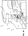
- FIG. 4 is a detailed view of FIG. 3A showing first seal land 88 extending partially toward second module radial wall surface 97.
- First seal land 88 of seal support ring 78 extends into cavity 74 toward second module 44.
- seal land 88 reduces the available flow area for leakage flow to enter cavity 74. Only a portion of leakage flow L then reaches second finger seal 82, which in turn protects outer cavity portion 94 and snaps 83.
- a seal support assembly is disposed proximate a joint between a first module and a second module.
- the seal support assembly includes a seal support ring with a backing ring mounted to a first module and a seal land extending partially across the joint toward the second module.
- the seal support ring includes a first seal land for a first finger seal, and the backing ring retains a fixed end of a second finger seal.
- the backing ring can also optionally be used to secure a fixed end of a heat shield element used to reduce radiative heating of the first module. Because the seal support assembly is a single piece, potential for installation damage is reduced or eliminated. Additionally, the seal support assembly can be easily repaired or replaced.
- seal support ring 78 is one illustrative example of an apparatus which can simultaneously provide sealing surface for free end 89 of first finger seal 80 at a location proximate cavity 74, as well as securing second finger seal 82 at a location within cavity 74.
- first finger seal 80 has a fixed seal end 92 adapted to be mounted to fairing assembly 48 passing generally axially through first gas turbine module 42.
- Seal support ring 78 also can include backing portion 84 for mounting ring 78 to first radial wall surface 94 of first outer case 54.
- First seal land 88 is also adapted to extend axially toward second outer case 56.
- Free end 95 of second finger seal 82 can also be adapted to prevent leakage gas flow L from entering radially outer cavity portion 94 and snap 83.
- Other examples of possible additions and modifications to seal support ring 78 and the surrounding region have also been described.
Landscapes
- Engineering & Computer Science (AREA)
- Mechanical Engineering (AREA)
- General Engineering & Computer Science (AREA)
- Chemical & Material Sciences (AREA)
- Combustion & Propulsion (AREA)
- Turbine Rotor Nozzle Sealing (AREA)
- Gasket Seals (AREA)
Description
- The described subject matter relates generally to gas turbine engines, and more particularly to sealing cavities between gas turbine engine modules.
- Gas turbine engines operate according to a continuous-flow, Brayton cycle. A compressor section pressurizes an ambient air stream, fuel is added and the mixture is burned in a central combustor section. The combustion products expand through a turbine section where bladed rotors convert thermal energy from the combustion products into mechanical energy for rotating one or more centrally mounted shafts. The shafts, in turn, drive the forward compressor section, thus continuing the cycle. Gas turbine engines are compact and powerful power plants, making them suitable for powering aircraft, heavy equipment, ships and electrical power generators. In power generating applications, the combustion products can also drive a separate power turbine attached to an electrical generator.
- For ease of assembly, gas turbine engines are typically designed in sections typically called modules. Each section is comprised of various components. The modules are then assembled together at the engine level. W-seals, feather seals, and/or dog-bone seals are typically used between modules to seal the modules against ingesting gas flow from a main gas flow passage of the gas turbine engine. However, these seals utilize a firm contacting interface that imparts a relatively large load on the modules to accomplish sealing. Additionally, seals can be damaged, for example, during engine level assembly when the modules are joined together.
- An assembly for a gas turbine engine, having the features of the preamble of claim 1 is disclosed in
US 3869222 A . - The present invention provides an assembly for a gas turbine engine as set forth in claim 1.
-
-
FIG. 1 schematically depicts an example gas turbine engine. -
FIG. 2 shows a cross-section of an engine assembly including a first module, a second module, and a first example embodiment of a seal assembly arranged together. -
FIG. 3A is an enlarged cross-section of the portion ofFIG. 2 showing the first example embodiment of the seal assembly. -
FIG. 3B isometrically depicts the first example embodiment of the seal assembly. -
FIG. 4 is a detailed cross-section of a portion ofFIG. 3A . - An exemplary industrial
gas turbine engine 10 is circumferentially disposed about a central, longitudinal axis or axialengine centerline axis 12 as illustrated inFIG. 1 . Theengine 10 includes in series order from front to rear, low and highpressure compressor sections central combustor section 20 and high and lowpressure turbine sections free turbine section 26 is disposed aft of thelow pressure turbine 24. Although illustrated with reference to an industrial gas turbine engine, this application also extends to aero engines with a fan or gear driven fan, and engines with more or fewer sections than illustrated. - As is well known in the art of gas turbines, incoming
ambient air 30 becomespressurized air 32 in thecompressors air 32 in thecombustor section 20, where it is burned to producecombustion gases 34 that expand as they flow throughturbine sections power turbine 26.Turbine sections pressure rotor shafts compressor sections Free turbine section 26 may, for example, drive an electrical generator, pump, or gearbox (not shown).Turbine assembly 40 also includes turbine exhaust case (TEC)assembly 42. As shown inFIG. 1 ,TEC assembly 42 can be disposed axially between lowpressure turbine section 24 andpower turbine 26.TEC assembly 42 is described in more detail below. - It is understood that
FIG. 1 provides a basic understanding and overview of the various sections and the basic operation of an industrial gas turbine engine. It will become apparent to those skilled in the art that the present application is applicable to all types of gas turbine engines, including those with aerospace applications. -
FIG. 2 showsturbine assembly 40, and also includesworking gas flow 34,first turbine module 42,second turbine module 44,module fasteners 45,frame 46,fairing assembly 48,stator vane 50, maingas flow passage 51,rotor blade 52, firstouter case 54, secondouter case 56, frameinner hub 58,frame strut 60, fairingouter platform 62, fairinginner platform 64,fairing strut liners 66,heat shield assembly 70,heat shield elements annular cavity 74, andseal assembly 76. -
FIG. 2 showsturbine assembly 40 which includesfirst module 42 andsecond module 44 interconnected byfasteners 45. Gas turbine engines typically are divided into modules for ease of assembly and design. Modules such asfirst module 42 andsecond module 44 are assembled separately, and then combined together at the engine level to create various engine portions illustrated forgas turbine engine 10 ofFIG. 1 . - For simplicity, this particular example is described with reference to turbine exhaust case (TEC)
assembly 42 being a first turbine module. However, it will be appreciated that a first module can comprise any suitable module ofgas turbine engine 10 such ascompressor sections turbine sections Second module 44 can similarly be a module secured downstream ofTEC assembly 42. - Among other components,
TEC assembly 42 includesframe 46 andfairing assembly 48.Second module 44 additionally houses components such asstator vane 50 androtor blade 52.TEC assembly 42 is connected tosecond module 44 such thatmodules radial cases TEC assembly 42 andsecond module 44 are connected such thatvane 50 andblade 52 are disposed downstream offrame 46 andfairing 48 with respect todirection 34 of combustion gases flowing along main enginegas flow passage 51. - In this example embodiment,
frame 46 includesouter case section 54 andinner hub 58, with a plurality of circumferentially distributedstruts 60 extending radially therebetween. Only onestrut 60 is shown inFIG. 2 . When assembled,fairing assembly 48 is secured over annular surfaces offrame 46 to define maingas flow passage 51. In this example,fairing assembly 48 includes individual fairing elements such asouter fairing platform 62,inner fairing platform 64, andstrut liners 66.Outer fairing platform 62 and innerradial platform 64 each have a generally conical shape and are retained over annular surfaces ofouter case 54 andinner hub 58. Innerradial platform 64 is spaced from outerradial platform 62 bystrut liners 66.Strut liners 66 are adapted to be disposed over annular surfaces ofstruts 60, which extend radially between innerradial platform 62 and outerradial platform 60. - While
fairing assembly 48 prevents direct contact of working fluid withframe 46, to provide further thermal control,heat shield assembly 70 can be disposed in a line of sight betweenfairing assembly 48 andframe 46.Heat shield elements TEC assembly 42 so as to reduce heating offrame 46 caused by thermal radiation emitted fromfairing assembly 48. - Annular cavities in and around
TEC assembly 42 andsecond module 44 can be sealed against intrusion of combustion or working gases from maingas flow passage 51. One such cavity isannular cavity 74 disposed proximate the joint betweenTEC assembly 42 andsecond module 44. One example means includesseal assembly 76 disposedproximate cavity 74, which is defined betweenTEC assembly 42 andsecond module 44.FIGS. 3-5 are detailed views ofcavity 74 andseal assembly 76 disposed proximate the joint betweenmodules -
FIG. 3A shows a detailed sectional view of a portion ofturbine assembly 40 withseal assembly 76 disposed incavity 74, whileFIG. 3B is a perspective view.FIGS. 3A and3B also include workinggas flow 34,first turbine module 42,second turbine module 44,module fasteners 45,frame 46, fairingassembly 48,stator vane 50, maingas flow passage 51, firstouter case 54, secondouter case 56, fairingouter platform 62,heat shield element 72A,support ring 78,first finger seal 80,second finger seal 82,snap 83,seal backing portion 84,seal ring fastener 85, fairingcavities radial wall surface 86,first seal land 88, first finger sealfree end 89, first seal landinner side 90, first finger seal fixedend 92, annular cavity radiallyouter portion 94, second finger sealfree end 95, second moduleradial wall surface 97, second finger seal fixedend 98, and heat shield fixedend 99. - As shown in
FIG. 2 ,TEC assembly 42 includesouter case section 54 andsecond module 42 includesouter case section 56. In this illustrative example,TEC assembly 42 comprises a turbine module (e.g., lowpressure turbine module 24 inFIG. 1 ) with a turbine exhaust case (TEC) assembly. Here,second module 44 comprises a power turbine module (e.g.,power turbine module 26 inFIG. 1 ). -
Seal assembly 76 includesseal support ring 78,first finger seal 80, andsecond finger seal 82. As shown inFIGS. 3A and3B ,outer case 54 can includesnap 83 that snaps into an interference fit with a mating portion ofouter case 56 along the joint betweenTEC assembly 42 andsecond module 44. As described previously,seal support ring 78 is mounted betweenTEC assembly 42 andsecond module 44 radially inward ofsnap 83 to support first and second finger seals 80, 82. -
Cavity 74 is formed along the joint betweenTEC assembly 42 andsecond module 44 and includesouter cavity portion 94.Seal assembly 76separates cavity 74 from fairing outerradial platform 62.Seal ring fasteners 85 are disposed withincavity 74 for mounting bothseal support ring 76 andsecond finger seal 82 toTEC assembly 42. Together, sealsupport ring 76 andsecond finger seal 82 cooperate to reduce the total leakage airflow L escaping maingas flow passage 51, and more particularly, limits leakage flow L that is able to reach radiallyouter cavity portion 94. -
Support ring 78 includes backingportion 84 secured toradial wall surface 86 ofTEC assembly 42. First sealland 88 extends axially intocavity 74 away fromTEC assembly 42. As shown inFIG. 3B ,seal support ring 78 can include a single unified generally L-shaped ring. A circumference ofseal support ring 78 can be similar to those ofouter cases seal support ring 78 may comprise a plurality of circumferentially distributed ring segments, and/or mounted tosecond module 44, rather thanTEC assembly 42. -
First finger seal 80 hasfree end 89 adapted to contactinner side 90 offirst seal land 88. This redirects a substantial portion of leakage flow L away from fairingcavities cavity 74 proximate an outer side ofouter fairing platform 62. In certain embodiments, fixedend 92 offirst finger seal 80 can be removably secured to an outer portion of fairingassembly 48 such as a flange or other projection disposed opposite the gas facing surface of outerradial platform 62. -
Second finger seal 82 can be adapted to seal radiallyouter portion 94 ofannular cavity 74 to prevent excessive heating ofouter case sections outer case sections gas flow passage 51.Second finger seal 82 helps provide further sealing ofouter cavity portion 94 against ingestion of leakage flow L. In certain embodiments,free end 95 ofsecond finger seal 82 extends partially towardsecond module 44.Radial wall surface 97 of second module 44 (a wall of cavity 74) is adapted to operate as a seal land forfree end 95 ofsecond finger seal 82. In certain embodiments, fixedend 98 ofsecond finger seal 82 can be secured to supportring backing portion 84 and TECassembly radial wall 86. In this configuration,second finger seal 82 can be disposed incavity 74 without additional mounting hardware thereby simplifying manufacture and assembly. - In operation, leakage gas flow L may pass from main engine
gas flow passage 51 aft of outerradial platform 62 and tends to flow toward a space betweenfairing assembly 48 and frame 46 (here, outer case 54).Seal assembly 76 operates in two stages to direct leakage gas flow L away from fairingcavities outer cavity portion 94. This protects the joint betweenTEC assembly 42 andsecond module 44.First finger seal 80 reduces ingestion of leakage flow L into fairingcavities fairing assembly 48 andframe 46. Most of the leakage flow L redirected towardcavity 74 is prevented from reachingouter cavity portion 94 and snaps 83 viasecond finger seal 82. -
Seal assembly 76 is shown and described as being disposed radially outward of main enginegas flow passage 51 and fairingassembly 48 inFIGS. 2-3B . However, in certain alternative exemplary embodiments ofseal assembly 76 can be disposed radially inward of main enginegas flow passage 51. - As described with respect to
FIG. 2 , sealsupport assembly 76 can optionally compriseheat shield 70. In certain examples,heat shield 70 comprises a plurality ofheat shield elements heat shield element 72A can be positioned or retained between TEC assembly 42A (specifically outer case section 54), and outerradial platform 62. In this example,first end 99 ofheat shield element 72A can be commonly secured to TEC assemblyradial wall surface 86, and to backingportion 84 ofseal support ring 78 viaseal ring fasteners 85. This allows controlled thermal growth ofheat shield element 76 so that at least a reflective portion ofelement 72A is retained in a line of sight betweenframe 46 and fairingassembly 48. -
FIG. 4 is a detailed view ofFIG. 3A showingfirst seal land 88 extending partially toward second moduleradial wall surface 97. First sealland 88 ofseal support ring 78 extends intocavity 74 towardsecond module 44. As shown inFIG. 4 , sealland 88 reduces the available flow area for leakage flow to entercavity 74. Only a portion of leakage flow L then reachessecond finger seal 82, which in turn protectsouter cavity portion 94 and snaps 83. - In this example embodiment, a seal support assembly is disposed proximate a joint between a first module and a second module. The seal support assembly includes a seal support ring with a backing ring mounted to a first module and a seal land extending partially across the joint toward the second module. The seal support ring includes a first seal land for a first finger seal, and the backing ring retains a fixed end of a second finger seal. The backing ring can also optionally be used to secure a fixed end of a heat shield element used to reduce radiative heating of the first module. Because the seal support assembly is a single piece, potential for installation damage is reduced or eliminated. Additionally, the seal support assembly can be easily repaired or replaced.
- Referring to
FIGS. 2-4 , sealsupport ring 78 is one illustrative example of an apparatus which can simultaneously provide sealing surface forfree end 89 offirst finger seal 80 at a locationproximate cavity 74, as well as securingsecond finger seal 82 at a location withincavity 74. As noted above,first finger seal 80 has a fixedseal end 92 adapted to be mounted to fairingassembly 48 passing generally axially through firstgas turbine module 42.Seal support ring 78 also can includebacking portion 84 for mountingring 78 to firstradial wall surface 94 of firstouter case 54. First sealland 88 is also adapted to extend axially toward secondouter case 56.Free end 95 ofsecond finger seal 82 can also be adapted to prevent leakage gas flow L from entering radiallyouter cavity portion 94 andsnap 83. Other examples of possible additions and modifications to sealsupport ring 78 and the surrounding region have also been described. - While the invention has been described with reference to an exemplary embodiment(s), it will be understood by those skilled in the art that various changes may be made and equivalents may be substituted for elements thereof without departing from the scope of the invention. In addition, many modifications may be made to adapt a particular situation or material to the teachings of the invention without departing from the essential scope thereof. Therefore, it is intended that the invention not be limited to the particular embodiment(s) disclosed, but that the invention will include all embodiments falling within the scope of the appended claims.
Claims (12)
- An assembly (40) for a gas turbine engine, comprising:a first module (42) including a first radial wall;a second module (44) including a second radial wall, the second module (44) interconnected with the first module (42) along a joint such that a surface (97) of the second radial wall faces a surface (86) of the first radial wall;a cavity (74) defined in part by the first radial wall and the second radial wall; anda seal assembly disposed proximate the cavity (74); wherein the seal assembly comprises:a seal support ring (78) including a backing ring portion (84) and a first seal land (88), the backing ring portion (84) secured to one of the first radial wall and the second radial wall, and the first seal land (88) extending axially into the cavity (74) toward the other of the first radial wall and the second radial wall;a first finger seal (80) including a fixed end (92) and a free end (89); anda second finger seal (82) secured in the cavity (74) between the first radial wall and the second radial wall, characterised in that the free end (89) of the first finger seal (80) contacts a radially inner side of the first seal land (88).
- The assembly of claim 1, wherein the fixed end of the first finger seal (80) is fastened to a radially outer surface of a fairing (48) extending generally axially through the first module (42).
- The assembly of claim 1 or 2, wherein a fixed end (98) of the second finger seal (82) is fastened between the backing ring portion (84), and the one of the first radial wall and the second radial wall.
- The assembly of claim 3, wherein a radial surface (97) of the other of the first radial wall and the second radial wall operates as a second seal land for a free end (95) of the second finger seal (82).
- The assembly of any preceding claim, further comprising a heat shield element (72A) with a fixed end fastened between the backing ring portion (84) of the seal support ring (78), and the one of the first radial wall surface (86) and the second radial wall surface (97).
- The assembly of claim 5, wherein a reflective portion of the heat shield element (72) is retained in a line of sight between the first module (42) and an outer fairing platform (62).
- The assembly of any preceding claim, wherein the first module (42) comprises an outer case section and the second module (44) comprises an outer case section.
- The assembly of any preceding claim, wherein:
the first module (42) comprises a turbine exhaust case (TEC) assembly. - The assembly of claim 8, wherein the backing ring portion (84) is secured to the first radial wall.
- The assembly of claim 9, wherein an upstream end of the second outer case (44) section is connected to a downstream end of the first outer case section (42).
- The assembly of claim 8 or 9, wherein the fixed end (92) of the first finger seal (80) is fastened to an outer side of a fairing platform (62) disposed radially inward of the first outer case section (42).
- The assembly of any preceding claim, wherein:
the second module (44) comprises a power turbine module.
Applications Claiming Priority (2)
| Application Number | Priority Date | Filing Date | Title |
|---|---|---|---|
| US201261747267P | 2012-12-29 | 2012-12-29 | |
| PCT/US2013/077442 WO2014105803A1 (en) | 2012-12-29 | 2013-12-23 | Gas turbine seal assembly and seal support |
Publications (3)
| Publication Number | Publication Date |
|---|---|
| EP2938837A1 EP2938837A1 (en) | 2015-11-04 |
| EP2938837A4 EP2938837A4 (en) | 2016-07-27 |
| EP2938837B1 true EP2938837B1 (en) | 2018-06-27 |
Family
ID=51022020
Family Applications (1)
| Application Number | Title | Priority Date | Filing Date |
|---|---|---|---|
| EP13868215.8A Active EP2938837B1 (en) | 2012-12-29 | 2013-12-23 | Gas turbine seal assembly and seal support |
Country Status (4)
| Country | Link |
|---|---|
| US (1) | US9903216B2 (en) |
| EP (1) | EP2938837B1 (en) |
| JP (1) | JP6271582B2 (en) |
| WO (1) | WO2014105803A1 (en) |
Families Citing this family (11)
| Publication number | Priority date | Publication date | Assignee | Title |
|---|---|---|---|---|
| EP2949873A1 (en) * | 2014-05-27 | 2015-12-02 | Siemens Aktiengesellschaft | Turbomachine with an ingestion shield and use of the turbomachine |
| US10415411B2 (en) * | 2014-12-12 | 2019-09-17 | United Technologies Corporation | Splined dog-bone seal |
| US20170051983A1 (en) * | 2015-08-18 | 2017-02-23 | Arvos Inc. | Flexible seal for a rotary regenerative preheater |
| EP3159505B1 (en) * | 2015-10-20 | 2020-01-08 | MTU Aero Engines GmbH | Intermediate casing for a gas turbine |
| DE102016202519A1 (en) * | 2016-02-18 | 2017-08-24 | MTU Aero Engines AG | Guide vane segment for a turbomachine |
| US10487943B2 (en) | 2016-07-12 | 2019-11-26 | United Technologies Corporation | Multi-ply seal ring |
| EP3385506B1 (en) * | 2017-04-07 | 2019-10-30 | MTU Aero Engines GmbH | Sealing arrangement for a gas turbine engine |
| US10830103B2 (en) * | 2017-07-05 | 2020-11-10 | General Electric Company | Expansion joint and methods of assembling the same |
| US10513939B2 (en) * | 2017-09-13 | 2019-12-24 | United Technologies Corporation | Seal interface with a deflection control feature |
| US10774685B2 (en) | 2018-04-30 | 2020-09-15 | Ratheon Technologies Corporation | Gas turbine engine exhaust component |
| CN110318829A (en) * | 2019-07-19 | 2019-10-11 | 中国航发沈阳发动机研究所 | A kind of elastic piece seal structure |
Family Cites Families (156)
| Publication number | Priority date | Publication date | Assignee | Title |
|---|---|---|---|---|
| US2214108A (en) | 1938-11-05 | 1940-09-10 | Gen Motors Corp | Manufacture of tubing |
| US4044555A (en) | 1958-09-30 | 1977-08-30 | Hayes International Corporation | Rear section of jet power plant installations |
| US3576328A (en) | 1968-03-22 | 1971-04-27 | Robert W Vose | High pressure seals |
| US3802046A (en) | 1972-01-27 | 1974-04-09 | Chromalloy American Corp | Method of making or reconditioning a turbine-nozzle or the like assembly |
| US3970319A (en) | 1972-11-17 | 1976-07-20 | General Motors Corporation | Seal structure |
| US3869222A (en) * | 1973-06-07 | 1975-03-04 | Ford Motor Co | Seal means for a gas turbine engine |
| US4022948A (en) | 1974-12-23 | 1977-05-10 | United Technologies Corporation | Resiliently coated metallic finger seals |
| US4009569A (en) | 1975-07-21 | 1977-03-01 | United Technologies Corporation | Diffuser-burner casing for a gas turbine engine |
| US4088422A (en) | 1976-10-01 | 1978-05-09 | General Electric Company | Flexible interstage turbine spacer |
| US4321007A (en) | 1979-12-21 | 1982-03-23 | United Technologies Corporation | Outer case cooling for a turbine intermediate case |
| US4369016A (en) | 1979-12-21 | 1983-01-18 | United Technologies Corporation | Turbine intermediate case |
| US4305697A (en) | 1980-03-19 | 1981-12-15 | General Electric Company | Method and replacement member for repairing a gas turbine engine vane assembly |
| US4478551A (en) | 1981-12-08 | 1984-10-23 | United Technologies Corporation | Turbine exhaust case design |
| GB8504331D0 (en) | 1985-02-20 | 1985-03-20 | Rolls Royce | Brush seals |
| US4645217A (en) | 1985-11-29 | 1987-02-24 | United Technologies Corporation | Finger seal assembly |
| GB2198195B (en) | 1986-12-06 | 1990-05-16 | Rolls Royce Plc | Brush seal |
| US5246295A (en) | 1991-10-30 | 1993-09-21 | Ide Russell D | Non-contacting mechanical face seal of the gap-type |
| US4793770A (en) | 1987-08-06 | 1988-12-27 | General Electric Company | Gas turbine engine frame assembly |
| US4738453A (en) | 1987-08-17 | 1988-04-19 | Ide Russell D | Hydrodynamic face seal with lift pads |
| US4883405A (en) | 1987-11-13 | 1989-11-28 | The United States Of America As Represented By The Secretary Of The Air Force | Turbine nozzle mounting arrangement |
| US4920742A (en) | 1988-05-31 | 1990-05-01 | General Electric Company | Heat shield for gas turbine engine frame |
| US4987736A (en) | 1988-12-14 | 1991-01-29 | General Electric Company | Lightweight gas turbine engine frame with free-floating heat shield |
| US4989406A (en) | 1988-12-29 | 1991-02-05 | General Electric Company | Turbine engine assembly with aft mounted outlet guide vanes |
| US4993918A (en) | 1989-05-19 | 1991-02-19 | United Technologies Corporation | Replaceable fairing for a turbine exhaust case |
| US5071138A (en) | 1989-12-21 | 1991-12-10 | Allied-Signal Inc. | Laminated finger seal |
| US5031922A (en) | 1989-12-21 | 1991-07-16 | Allied-Signal Inc. | Bidirectional finger seal |
| US5042823A (en) | 1989-12-21 | 1991-08-27 | Allied-Signal Inc. | Laminated finger seal |
| US5076049A (en) | 1990-04-02 | 1991-12-31 | General Electric Company | Pretensioned frame |
| US5100158A (en) | 1990-08-16 | 1992-03-31 | Eg&G Sealol, Inc. | Compliant finer seal |
| GB9020317D0 (en) | 1990-09-18 | 1990-10-31 | Cross Mfg Co | Sealing devices |
| US5224822A (en) | 1991-05-13 | 1993-07-06 | General Electric Company | Integral turbine nozzle support and discourager seal |
| US5108116A (en) | 1991-05-31 | 1992-04-28 | Allied-Signal Inc. | Laminated finger seal with logarithmic curvature |
| US5174584A (en) | 1991-07-15 | 1992-12-29 | General Electric Company | Fluid bearing face seal for gas turbine engines |
| US5169159A (en) | 1991-09-30 | 1992-12-08 | General Electric Company | Effective sealing device for engine flowpath |
| US5236302A (en) | 1991-10-30 | 1993-08-17 | General Electric Company | Turbine disk interstage seal system |
| US5188507A (en) | 1991-11-27 | 1993-02-23 | General Electric Company | Low-pressure turbine shroud |
| FR2685381B1 (en) | 1991-12-18 | 1994-02-11 | Snecma | TURBINE HOUSING BOUNDING AN ANNULAR GAS FLOW VEIN DIVIDED BY RADIAL ARMS. |
| US5211541A (en) | 1991-12-23 | 1993-05-18 | General Electric Company | Turbine support assembly including turbine heat shield and bolt retainer assembly |
| US5269057A (en) | 1991-12-24 | 1993-12-14 | Freedom Forge Corporation | Method of making replacement airfoil components |
| US5265807A (en) | 1992-06-01 | 1993-11-30 | Rohr, Inc. | Aerodynamic stiffening ring for an aircraft turbine engine mixer |
| GB2267736B (en) | 1992-06-09 | 1995-08-09 | Gen Electric | Segmented turbine flowpath assembly |
| US5272869A (en) | 1992-12-10 | 1993-12-28 | General Electric Company | Turbine frame |
| US5292227A (en) | 1992-12-10 | 1994-03-08 | General Electric Company | Turbine frame |
| US5273397A (en) | 1993-01-13 | 1993-12-28 | General Electric Company | Turbine casing and radiation shield |
| US5338154A (en) | 1993-03-17 | 1994-08-16 | General Electric Company | Turbine disk interstage seal axial retaining ring |
| US5401036A (en) | 1993-03-22 | 1995-03-28 | Eg & G Sealol, Inc. | Brush seal device having a recessed back plate |
| US5483792A (en) | 1993-05-05 | 1996-01-16 | General Electric Company | Turbine frame stiffening rails |
| US5370402A (en) | 1993-05-07 | 1994-12-06 | Eg&G Sealol, Inc. | Pressure balanced compliant seal device |
| US5691279A (en) | 1993-06-22 | 1997-11-25 | The United States Of America As Represented By The Secretary Of The Army | C-axis oriented high temperature superconductors deposited onto new compositions of garnet |
| US5438756A (en) | 1993-12-17 | 1995-08-08 | General Electric Company | Method for assembling a turbine frame assembly |
| US5558341A (en) | 1995-01-11 | 1996-09-24 | Stein Seal Company | Seal for sealing an incompressible fluid between a relatively stationary seal and a movable member |
| US5632493A (en) | 1995-05-04 | 1997-05-27 | Eg&G Sealol, Inc. | Compliant pressure balanced seal apparatus |
| US5851105A (en) | 1995-06-28 | 1998-12-22 | General Electric Company | Tapered strut frame |
| DE19535945A1 (en) | 1995-09-27 | 1997-04-03 | Hydraulik Ring Gmbh | Solenoid valve and method for its production |
| US5609467A (en) | 1995-09-28 | 1997-03-11 | Cooper Cameron Corporation | Floating interturbine duct assembly for high temperature power turbine |
| US5597286A (en) | 1995-12-21 | 1997-01-28 | General Electric Company | Turbine frame static seal |
| US5605438A (en) | 1995-12-29 | 1997-02-25 | General Electric Co. | Casing distortion control for rotating machinery |
| US5634767A (en) | 1996-03-29 | 1997-06-03 | General Electric Company | Turbine frame having spindle mounted liner |
| US5755445A (en) | 1996-08-23 | 1998-05-26 | Alliedsignal Inc. | Noncontacting finger seal with hydrodynamic foot portion |
| JP3403073B2 (en) | 1997-08-26 | 2003-05-06 | キヤノン株式会社 | Sheet feeding device and image processing device |
| FR2777318B1 (en) | 1998-04-09 | 2000-05-12 | Snecma | PROCESS FOR REDUCING THE EXISTING CLEARANCE BETWEEN A SHIRT AND A TURBINE DISTRIBUTOR OF A TURBOREACTOR |
| US6227800B1 (en) | 1998-11-24 | 2001-05-08 | General Electric Company | Bay cooled turbine casing |
| US6364316B1 (en) | 1999-02-11 | 2002-04-02 | Honeywell International Inc. | Dual pressure balanced noncontacting finger seal |
| US6196550B1 (en) | 1999-02-11 | 2001-03-06 | Alliedsignal Inc. | Pressure balanced finger seal |
| US6343912B1 (en) | 1999-12-07 | 2002-02-05 | General Electric Company | Gas turbine or jet engine stator vane frame |
| US6439841B1 (en) | 2000-04-29 | 2002-08-27 | General Electric Company | Turbine frame assembly |
| US6358001B1 (en) | 2000-04-29 | 2002-03-19 | General Electric Company | Turbine frame assembly |
| JP4410425B2 (en) | 2001-03-05 | 2010-02-03 | 三菱重工業株式会社 | Cooled gas turbine exhaust casing |
| US6511284B2 (en) | 2001-06-01 | 2003-01-28 | General Electric Company | Methods and apparatus for minimizing gas turbine engine thermal stress |
| JP4689882B2 (en) | 2001-06-29 | 2011-05-25 | イーグル工業株式会社 | Plate brush seal device |
| US20030025274A1 (en) | 2001-08-02 | 2003-02-06 | Honeywell International, Inc. | Laminated finger seal with stress reduction |
| JP4824225B2 (en) | 2001-08-29 | 2011-11-30 | イーグル工業株式会社 | Plate brush seal device |
| SE519781C2 (en) | 2001-08-29 | 2003-04-08 | Volvo Aero Corp | Process for producing a stator or rotor component |
| JP4751552B2 (en) | 2001-09-28 | 2011-08-17 | イーグル工業株式会社 | Plate brush seal and plate brush seal device |
| JP4675530B2 (en) | 2001-09-28 | 2011-04-27 | イーグル工業株式会社 | Plate brush seal |
| US6612807B2 (en) | 2001-11-15 | 2003-09-02 | General Electric Company | Frame hub heating system |
| US6612809B2 (en) | 2001-11-28 | 2003-09-02 | General Electric Company | Thermally compliant discourager seal |
| US6672833B2 (en) | 2001-12-18 | 2004-01-06 | General Electric Company | Gas turbine engine frame flowpath liner support |
| US6736401B2 (en) | 2001-12-19 | 2004-05-18 | Honeywell International, Inc. | Laminated finger seal with ceramic composition |
| US6796765B2 (en) | 2001-12-27 | 2004-09-28 | General Electric Company | Methods and apparatus for assembling gas turbine engine struts |
| DE10303088B4 (en) | 2002-02-09 | 2015-08-20 | Alstom Technology Ltd. | Exhaust casing of a heat engine |
| US6719524B2 (en) | 2002-02-25 | 2004-04-13 | Honeywell International Inc. | Method of forming a thermally isolated gas turbine engine housing |
| US6638013B2 (en) | 2002-02-25 | 2003-10-28 | Honeywell International Inc. | Thermally isolated housing in gas turbine engine |
| US6652229B2 (en) | 2002-02-27 | 2003-11-25 | General Electric Company | Leaf seal support for inner band of a turbine nozzle in a gas turbine engine |
| US6619030B1 (en) | 2002-03-01 | 2003-09-16 | General Electric Company | Aircraft engine with inter-turbine engine frame supported counter rotating low pressure turbine rotors |
| JP4054607B2 (en) | 2002-05-23 | 2008-02-27 | イーグル工業株式会社 | Plate brush seal |
| US7200933B2 (en) | 2002-08-14 | 2007-04-10 | Volvo Aero Corporation | Method for manufacturing a stator component |
| US7614150B2 (en) | 2002-08-14 | 2009-11-10 | Volvo Aero Corporation | Method for manufacturing a stator or rotor component |
| US6783324B2 (en) | 2002-08-15 | 2004-08-31 | General Electric Company | Compressor bleed case |
| US6792758B2 (en) | 2002-11-07 | 2004-09-21 | Siemens Westinghouse Power Corporation | Variable exhaust struts shields |
| US6811154B2 (en) | 2003-02-08 | 2004-11-02 | The United States Of America As Represented By The Administrator Of The National Aeronautics And Space Administration | Noncontacting finger seal |
| SE525879C2 (en) | 2003-03-21 | 2005-05-17 | Volvo Aero Corp | Process for manufacturing a stator component |
| JP4284643B2 (en) | 2003-04-16 | 2009-06-24 | 株式会社Ihi | Turbine nozzle cooling structure of gas turbine |
| US6983608B2 (en) | 2003-12-22 | 2006-01-10 | General Electric Company | Methods and apparatus for assembling gas turbine engines |
| US6969826B2 (en) | 2004-04-08 | 2005-11-29 | General Electric Company | Welding process |
| US7094026B2 (en) | 2004-04-29 | 2006-08-22 | General Electric Company | System for sealing an inner retainer segment and support ring in a gas turbine and methods therefor |
| US7238008B2 (en) | 2004-05-28 | 2007-07-03 | General Electric Company | Turbine blade retainer seal |
| US7100358B2 (en) | 2004-07-16 | 2006-09-05 | Pratt & Whitney Canada Corp. | Turbine exhaust case and method of making |
| US7229249B2 (en) | 2004-08-27 | 2007-06-12 | Pratt & Whitney Canada Corp. | Lightweight annular interturbine duct |
| US7147429B2 (en) * | 2004-09-16 | 2006-12-12 | General Electric Company | Turbine assembly and turbine shroud therefor |
| US7527469B2 (en) | 2004-12-10 | 2009-05-05 | Siemens Energy, Inc. | Transition-to-turbine seal apparatus and kit for transition/turbine junction of a gas turbine engine |
| US7367567B2 (en) | 2005-03-02 | 2008-05-06 | United Technologies Corporation | Low leakage finger seal |
| US7744709B2 (en) | 2005-08-22 | 2010-06-29 | United Technologies Corporation | Welding repair method for full hoop structures |
| FR2891301B1 (en) | 2005-09-29 | 2007-11-02 | Snecma Sa | STRUCTURAL CASING OF TURBOMOTEUR |
| US7371044B2 (en) | 2005-10-06 | 2008-05-13 | Siemens Power Generation, Inc. | Seal plate for turbine rotor assembly between turbine blade and turbine vane |
| JP2007120340A (en) | 2005-10-26 | 2007-05-17 | Mitsubishi Heavy Ind Ltd | Combustor tail pipe seal structure of gas turbine |
| FR2898641B1 (en) | 2006-03-17 | 2008-05-02 | Snecma Sa | CARTERING IN A TURBOJET ENGINE |
| US7677047B2 (en) | 2006-03-29 | 2010-03-16 | United Technologies Corporation | Inverted stiffened shell panel torque transmission for loaded struts and mid-turbine frames |
| US7631879B2 (en) | 2006-06-21 | 2009-12-15 | General Electric Company | “L” butt gap seal between segments in seal assemblies |
| US20100236244A1 (en) | 2006-06-28 | 2010-09-23 | Longardner Robert L | Heat absorbing and reflecting shield for air breathing heat engine |
| US7815417B2 (en) | 2006-09-01 | 2010-10-19 | United Technologies Corporation | Guide vane for a gas turbine engine |
| US7798768B2 (en) | 2006-10-25 | 2010-09-21 | Siemens Energy, Inc. | Turbine vane ID support |
| US7735833B2 (en) | 2006-11-14 | 2010-06-15 | The University Of Akron | Double padded finger seal |
| US7959409B2 (en) | 2007-03-01 | 2011-06-14 | Honeywell International Inc. | Repaired vane assemblies and methods of repairing vane assemblies |
| US20080216300A1 (en) | 2007-03-06 | 2008-09-11 | United Technologies Corporation | Splitter fairing repair |
| FR2914017B1 (en) | 2007-03-20 | 2011-07-08 | Snecma | SEALING DEVICE FOR A COOLING CIRCUIT, INTER-TURBINE HOUSING BEING EQUIPPED AND TURBOREACTOR COMPRISING THE SAME |
| US7824152B2 (en) | 2007-05-09 | 2010-11-02 | Siemens Energy, Inc. | Multivane segment mounting arrangement for a gas turbine |
| FR2917458B1 (en) | 2007-06-13 | 2009-09-25 | Snecma Sa | EXHAUST CASING HUB COMPRISING STRESS DISTRIBUTION RIBS |
| DE102007042767A1 (en) | 2007-09-07 | 2009-03-12 | Mtu Aero Engines Gmbh | Multilayer shielding ring for a propulsion system |
| FR2925119A1 (en) | 2007-12-14 | 2009-06-19 | Snecma Sa | SEALING A HUB CAVITY OF AN EXHAUST CASE IN A TURBOMACHINE |
| US8312726B2 (en) | 2007-12-21 | 2012-11-20 | United Technologies Corp. | Gas turbine engine systems involving I-beam struts |
| WO2009108084A1 (en) | 2008-02-25 | 2009-09-03 | Volvo Aero Corporation | A gas turbine component and a method for producing a gas turbine component |
| WO2009107438A1 (en) | 2008-02-27 | 2009-09-03 | 三菱重工業株式会社 | Connection structure of exhaust chamber, support structure of turbine, and gas turbine |
| US8016297B2 (en) * | 2008-03-27 | 2011-09-13 | United Technologies Corporation | Gas turbine engine seals and engines incorporating such seals |
| WO2009157817A1 (en) | 2008-06-26 | 2009-12-30 | Volvo Aero Corporation | Vane assembly and method of fabricating, and a turbo-machine with such vane assembly |
| US8069648B2 (en) | 2008-07-03 | 2011-12-06 | United Technologies Corporation | Impingement cooling for turbofan exhaust assembly |
| WO2010002295A1 (en) | 2008-07-04 | 2010-01-07 | Volvo Aero Corporation | A welding method |
| US8083465B2 (en) | 2008-09-05 | 2011-12-27 | United Technologies Corporation | Repaired turbine exhaust strut heat shield vanes and repair methods |
| US8092161B2 (en) | 2008-09-24 | 2012-01-10 | Siemens Energy, Inc. | Thermal shield at casing joint |
| US8221071B2 (en) | 2008-09-30 | 2012-07-17 | General Electric Company | Integrated guide vane assembly |
| US20100132377A1 (en) | 2008-11-28 | 2010-06-03 | Pratt & Whitney Canada Corp. | Fabricated itd-strut and vane ring for gas turbine engine |
| US20100132371A1 (en) | 2008-11-28 | 2010-06-03 | Pratt & Whitney Canada Corp. | Mid turbine frame system for gas turbine engine |
| US8091371B2 (en) | 2008-11-28 | 2012-01-10 | Pratt & Whitney Canada Corp. | Mid turbine frame for gas turbine engine |
| US8245518B2 (en) | 2008-11-28 | 2012-08-21 | Pratt & Whitney Canada Corp. | Mid turbine frame system for gas turbine engine |
| US8177488B2 (en) | 2008-11-29 | 2012-05-15 | General Electric Company | Integrated service tube and impingement baffle for a gas turbine engine |
| US8152451B2 (en) | 2008-11-29 | 2012-04-10 | General Electric Company | Split fairing for a gas turbine engine |
| US8371812B2 (en) | 2008-11-29 | 2013-02-12 | General Electric Company | Turbine frame assembly and method for a gas turbine engine |
| EP2379845A4 (en) | 2008-12-18 | 2013-08-07 | Gkn Aerospace Sweden Ab | Gas turbine composite workpiece to be used in gas turbine engine |
| US8245399B2 (en) | 2009-01-20 | 2012-08-21 | United Technologies Corporation | Replacement of part of engine case with dissimilar material |
| GB2467790B (en) | 2009-02-16 | 2011-06-01 | Rolls Royce Plc | Vane |
| US8408011B2 (en) | 2009-04-30 | 2013-04-02 | Pratt & Whitney Canada Corp. | Structural reinforcement strut for gas turbine case |
| US20100275572A1 (en) | 2009-04-30 | 2010-11-04 | Pratt & Whitney Canada Corp. | Oil line insulation system for mid turbine frame |
| US9003812B2 (en) | 2009-05-08 | 2015-04-14 | Gkn Aerospace Sweden Ab | Supporting structure for a gas turbine engine |
| US8491259B2 (en) | 2009-08-26 | 2013-07-23 | Siemens Energy, Inc. | Seal system between transition duct exit section and turbine inlet in a gas turbine engine |
| US20110061767A1 (en) | 2009-09-14 | 2011-03-17 | United Technologies Corporation | Component removal tool and method |
| US8371127B2 (en) | 2009-10-01 | 2013-02-12 | Pratt & Whitney Canada Corp. | Cooling air system for mid turbine frame |
| US8469661B2 (en) | 2009-10-01 | 2013-06-25 | Pratt & Whitney Canada Corp. | Fabricated gas turbine vane ring |
| US8740557B2 (en) | 2009-10-01 | 2014-06-03 | Pratt & Whitney Canada Corp. | Fabricated static vane ring |
| US8596959B2 (en) | 2009-10-09 | 2013-12-03 | Pratt & Whitney Canada Corp. | Oil tube with integrated heat shield |
| US8776533B2 (en) | 2010-03-08 | 2014-07-15 | United Technologies Corporation | Strain tolerant bound structure for a gas turbine engine |
| CH703309A1 (en) | 2010-06-10 | 2011-12-15 | Alstom Technology Ltd | Exhaust housing for a gas turbine and method for producing such an exhaust housing. |
| US20120156020A1 (en) | 2010-12-20 | 2012-06-21 | General Electric Company | Method of repairing a transition piece of a gas turbine engine |
| JP5726545B2 (en) | 2011-01-24 | 2015-06-03 | 株式会社東芝 | Transition piece damage repair method and transition piece |
| US9279368B2 (en) | 2011-02-11 | 2016-03-08 | Eagleburgmann Ke, Inc. | Apparatus and methods for eliminating cracking in a turbine exhaust shield |
| EP2710228B1 (en) | 2011-05-16 | 2017-11-01 | GKN Aerospace Sweden AB | Fairing of a gas turbine structure |
| US8770924B2 (en) | 2011-07-07 | 2014-07-08 | Siemens Energy, Inc. | Gas turbine engine with angled and radial supports |
-
2013
- 2013-12-23 JP JP2015550724A patent/JP6271582B2/en active Active
- 2013-12-23 WO PCT/US2013/077442 patent/WO2014105803A1/en active Application Filing
- 2013-12-23 EP EP13868215.8A patent/EP2938837B1/en active Active
- 2013-12-23 US US14/655,640 patent/US9903216B2/en active Active
Non-Patent Citations (1)
| Title |
|---|
| None * |
Also Published As
| Publication number | Publication date |
|---|---|
| JP6271582B2 (en) | 2018-01-31 |
| EP2938837A4 (en) | 2016-07-27 |
| JP2016506475A (en) | 2016-03-03 |
| US20150330241A1 (en) | 2015-11-19 |
| EP2938837A1 (en) | 2015-11-04 |
| US9903216B2 (en) | 2018-02-27 |
| WO2014105803A1 (en) | 2014-07-03 |
Similar Documents
| Publication | Publication Date | Title |
|---|---|---|
| EP2938837B1 (en) | Gas turbine seal assembly and seal support | |
| US9845695B2 (en) | Gas turbine seal assembly and seal support | |
| US9879556B2 (en) | Cooled finger seal | |
| US10053998B2 (en) | Multi-purpose gas turbine seal support and assembly | |
| EP2938836B1 (en) | Seal support disk and assembly | |
| US9562478B2 (en) | Inter-module finger seal | |
| US9297312B2 (en) | Circumferentially retained fairing | |
| US20140245751A1 (en) | Passages to facilitate a secondary flow between components | |
| EP2938867B1 (en) | Flow diverter to redirect secondary flow | |
| EP2938842B1 (en) | Plate for directing flow and film cooling of components | |
| US20140248127A1 (en) | Turbine engine component with dual purpose rib | |
| EP2938857B2 (en) | Heat shield for cooling a strut | |
| US10472987B2 (en) | Heat shield for a casing | |
| EP2938838B1 (en) | Inter-module flow discourager |
Legal Events
| Date | Code | Title | Description |
|---|---|---|---|
| PUAI | Public reference made under article 153(3) epc to a published international application that has entered the european phase |
Free format text: ORIGINAL CODE: 0009012 |
|
| 17P | Request for examination filed |
Effective date: 20150727 |
|
| AK | Designated contracting states |
Kind code of ref document: A1 Designated state(s): AL AT BE BG CH CY CZ DE DK EE ES FI FR GB GR HR HU IE IS IT LI LT LU LV MC MK MT NL NO PL PT RO RS SE SI SK SM TR |
|
| AX | Request for extension of the european patent |
Extension state: BA ME |
|
| DAX | Request for extension of the european patent (deleted) | ||
| REG | Reference to a national code |
Ref country code: DE Ref legal event code: R079 Ref document number: 602013039552 Country of ref document: DE Free format text: PREVIOUS MAIN CLASS: F01D0011020000 Ipc: F01D0025160000 |
|
| A4 | Supplementary search report drawn up and despatched |
Effective date: 20160624 |
|
| RIC1 | Information provided on ipc code assigned before grant |
Ipc: F01D 25/16 20060101AFI20160620BHEP Ipc: F01D 11/00 20060101ALI20160620BHEP |
|
| RAP1 | Party data changed (applicant data changed or rights of an application transferred) |
Owner name: UNITED TECHNOLOGIES CORPORATION |
|
| GRAP | Despatch of communication of intention to grant a patent |
Free format text: ORIGINAL CODE: EPIDOSNIGR1 |
|
| INTG | Intention to grant announced |
Effective date: 20180108 |
|
| GRAS | Grant fee paid |
Free format text: ORIGINAL CODE: EPIDOSNIGR3 |
|
| GRAA | (expected) grant |
Free format text: ORIGINAL CODE: 0009210 |
|
| AK | Designated contracting states |
Kind code of ref document: B1 Designated state(s): AL AT BE BG CH CY CZ DE DK EE ES FI FR GB GR HR HU IE IS IT LI LT LU LV MC MK MT NL NO PL PT RO RS SE SI SK SM TR |
|
| REG | Reference to a national code |
Ref country code: GB Ref legal event code: FG4D |
|
| REG | Reference to a national code |
Ref country code: AT Ref legal event code: REF Ref document number: 1012541 Country of ref document: AT Kind code of ref document: T Effective date: 20180715 |
|
| REG | Reference to a national code |
Ref country code: IE Ref legal event code: FG4D |
|
| REG | Reference to a national code |
Ref country code: DE Ref legal event code: R096 Ref document number: 602013039552 Country of ref document: DE |
|
| PG25 | Lapsed in a contracting state [announced via postgrant information from national office to epo] |
Ref country code: NO Free format text: LAPSE BECAUSE OF FAILURE TO SUBMIT A TRANSLATION OF THE DESCRIPTION OR TO PAY THE FEE WITHIN THE PRESCRIBED TIME-LIMIT Effective date: 20180927 Ref country code: LT Free format text: LAPSE BECAUSE OF FAILURE TO SUBMIT A TRANSLATION OF THE DESCRIPTION OR TO PAY THE FEE WITHIN THE PRESCRIBED TIME-LIMIT Effective date: 20180627 Ref country code: SE Free format text: LAPSE BECAUSE OF FAILURE TO SUBMIT A TRANSLATION OF THE DESCRIPTION OR TO PAY THE FEE WITHIN THE PRESCRIBED TIME-LIMIT Effective date: 20180627 Ref country code: FI Free format text: LAPSE BECAUSE OF FAILURE TO SUBMIT A TRANSLATION OF THE DESCRIPTION OR TO PAY THE FEE WITHIN THE PRESCRIBED TIME-LIMIT Effective date: 20180627 Ref country code: BG Free format text: LAPSE BECAUSE OF FAILURE TO SUBMIT A TRANSLATION OF THE DESCRIPTION OR TO PAY THE FEE WITHIN THE PRESCRIBED TIME-LIMIT Effective date: 20180927 |
|
| REG | Reference to a national code |
Ref country code: NL Ref legal event code: MP Effective date: 20180627 |
|
| REG | Reference to a national code |
Ref country code: LT Ref legal event code: MG4D |
|
| PG25 | Lapsed in a contracting state [announced via postgrant information from national office to epo] |
Ref country code: HR Free format text: LAPSE BECAUSE OF FAILURE TO SUBMIT A TRANSLATION OF THE DESCRIPTION OR TO PAY THE FEE WITHIN THE PRESCRIBED TIME-LIMIT Effective date: 20180627 Ref country code: LV Free format text: LAPSE BECAUSE OF FAILURE TO SUBMIT A TRANSLATION OF THE DESCRIPTION OR TO PAY THE FEE WITHIN THE PRESCRIBED TIME-LIMIT Effective date: 20180627 Ref country code: RS Free format text: LAPSE BECAUSE OF FAILURE TO SUBMIT A TRANSLATION OF THE DESCRIPTION OR TO PAY THE FEE WITHIN THE PRESCRIBED TIME-LIMIT Effective date: 20180627 Ref country code: GR Free format text: LAPSE BECAUSE OF FAILURE TO SUBMIT A TRANSLATION OF THE DESCRIPTION OR TO PAY THE FEE WITHIN THE PRESCRIBED TIME-LIMIT Effective date: 20180928 |
|
| REG | Reference to a national code |
Ref country code: AT Ref legal event code: MK05 Ref document number: 1012541 Country of ref document: AT Kind code of ref document: T Effective date: 20180627 |
|
| PG25 | Lapsed in a contracting state [announced via postgrant information from national office to epo] |
Ref country code: NL Free format text: LAPSE BECAUSE OF FAILURE TO SUBMIT A TRANSLATION OF THE DESCRIPTION OR TO PAY THE FEE WITHIN THE PRESCRIBED TIME-LIMIT Effective date: 20180627 |
|
| PG25 | Lapsed in a contracting state [announced via postgrant information from national office to epo] |
Ref country code: EE Free format text: LAPSE BECAUSE OF FAILURE TO SUBMIT A TRANSLATION OF THE DESCRIPTION OR TO PAY THE FEE WITHIN THE PRESCRIBED TIME-LIMIT Effective date: 20180627 Ref country code: IS Free format text: LAPSE BECAUSE OF FAILURE TO SUBMIT A TRANSLATION OF THE DESCRIPTION OR TO PAY THE FEE WITHIN THE PRESCRIBED TIME-LIMIT Effective date: 20181027 Ref country code: PL Free format text: LAPSE BECAUSE OF FAILURE TO SUBMIT A TRANSLATION OF THE DESCRIPTION OR TO PAY THE FEE WITHIN THE PRESCRIBED TIME-LIMIT Effective date: 20180627 Ref country code: SK Free format text: LAPSE BECAUSE OF FAILURE TO SUBMIT A TRANSLATION OF THE DESCRIPTION OR TO PAY THE FEE WITHIN THE PRESCRIBED TIME-LIMIT Effective date: 20180627 Ref country code: RO Free format text: LAPSE BECAUSE OF FAILURE TO SUBMIT A TRANSLATION OF THE DESCRIPTION OR TO PAY THE FEE WITHIN THE PRESCRIBED TIME-LIMIT Effective date: 20180627 Ref country code: AT Free format text: LAPSE BECAUSE OF FAILURE TO SUBMIT A TRANSLATION OF THE DESCRIPTION OR TO PAY THE FEE WITHIN THE PRESCRIBED TIME-LIMIT Effective date: 20180627 Ref country code: CZ Free format text: LAPSE BECAUSE OF FAILURE TO SUBMIT A TRANSLATION OF THE DESCRIPTION OR TO PAY THE FEE WITHIN THE PRESCRIBED TIME-LIMIT Effective date: 20180627 |
|
| PG25 | Lapsed in a contracting state [announced via postgrant information from national office to epo] |
Ref country code: ES Free format text: LAPSE BECAUSE OF FAILURE TO SUBMIT A TRANSLATION OF THE DESCRIPTION OR TO PAY THE FEE WITHIN THE PRESCRIBED TIME-LIMIT Effective date: 20180627 Ref country code: IT Free format text: LAPSE BECAUSE OF FAILURE TO SUBMIT A TRANSLATION OF THE DESCRIPTION OR TO PAY THE FEE WITHIN THE PRESCRIBED TIME-LIMIT Effective date: 20180627 Ref country code: SM Free format text: LAPSE BECAUSE OF FAILURE TO SUBMIT A TRANSLATION OF THE DESCRIPTION OR TO PAY THE FEE WITHIN THE PRESCRIBED TIME-LIMIT Effective date: 20180627 |
|
| REG | Reference to a national code |
Ref country code: DE Ref legal event code: R097 Ref document number: 602013039552 Country of ref document: DE |
|
| PLBE | No opposition filed within time limit |
Free format text: ORIGINAL CODE: 0009261 |
|
| STAA | Information on the status of an ep patent application or granted ep patent |
Free format text: STATUS: NO OPPOSITION FILED WITHIN TIME LIMIT |
|
| PG25 | Lapsed in a contracting state [announced via postgrant information from national office to epo] |
Ref country code: DK Free format text: LAPSE BECAUSE OF FAILURE TO SUBMIT A TRANSLATION OF THE DESCRIPTION OR TO PAY THE FEE WITHIN THE PRESCRIBED TIME-LIMIT Effective date: 20180627 |
|
| 26N | No opposition filed |
Effective date: 20190328 |
|
| REG | Reference to a national code |
Ref country code: CH Ref legal event code: PL |
|
| PG25 | Lapsed in a contracting state [announced via postgrant information from national office to epo] |
Ref country code: SI Free format text: LAPSE BECAUSE OF FAILURE TO SUBMIT A TRANSLATION OF THE DESCRIPTION OR TO PAY THE FEE WITHIN THE PRESCRIBED TIME-LIMIT Effective date: 20180627 Ref country code: LU Free format text: LAPSE BECAUSE OF NON-PAYMENT OF DUE FEES Effective date: 20181223 Ref country code: MC Free format text: LAPSE BECAUSE OF FAILURE TO SUBMIT A TRANSLATION OF THE DESCRIPTION OR TO PAY THE FEE WITHIN THE PRESCRIBED TIME-LIMIT Effective date: 20180627 |
|
| REG | Reference to a national code |
Ref country code: IE Ref legal event code: MM4A |
|
| REG | Reference to a national code |
Ref country code: BE Ref legal event code: MM Effective date: 20181231 |
|
| PG25 | Lapsed in a contracting state [announced via postgrant information from national office to epo] |
Ref country code: IE Free format text: LAPSE BECAUSE OF NON-PAYMENT OF DUE FEES Effective date: 20181223 |
|
| PG25 | Lapsed in a contracting state [announced via postgrant information from national office to epo] |
Ref country code: AL Free format text: LAPSE BECAUSE OF FAILURE TO SUBMIT A TRANSLATION OF THE DESCRIPTION OR TO PAY THE FEE WITHIN THE PRESCRIBED TIME-LIMIT Effective date: 20180627 Ref country code: BE Free format text: LAPSE BECAUSE OF NON-PAYMENT OF DUE FEES Effective date: 20181231 |
|
| PG25 | Lapsed in a contracting state [announced via postgrant information from national office to epo] |
Ref country code: LI Free format text: LAPSE BECAUSE OF NON-PAYMENT OF DUE FEES Effective date: 20181231 Ref country code: CH Free format text: LAPSE BECAUSE OF NON-PAYMENT OF DUE FEES Effective date: 20181231 |
|
| PG25 | Lapsed in a contracting state [announced via postgrant information from national office to epo] |
Ref country code: MT Free format text: LAPSE BECAUSE OF NON-PAYMENT OF DUE FEES Effective date: 20181223 |
|
| PG25 | Lapsed in a contracting state [announced via postgrant information from national office to epo] |
Ref country code: TR Free format text: LAPSE BECAUSE OF FAILURE TO SUBMIT A TRANSLATION OF THE DESCRIPTION OR TO PAY THE FEE WITHIN THE PRESCRIBED TIME-LIMIT Effective date: 20180627 |
|
| PG25 | Lapsed in a contracting state [announced via postgrant information from national office to epo] |
Ref country code: PT Free format text: LAPSE BECAUSE OF FAILURE TO SUBMIT A TRANSLATION OF THE DESCRIPTION OR TO PAY THE FEE WITHIN THE PRESCRIBED TIME-LIMIT Effective date: 20180627 |
|
| PG25 | Lapsed in a contracting state [announced via postgrant information from national office to epo] |
Ref country code: HU Free format text: LAPSE BECAUSE OF FAILURE TO SUBMIT A TRANSLATION OF THE DESCRIPTION OR TO PAY THE FEE WITHIN THE PRESCRIBED TIME-LIMIT; INVALID AB INITIO Effective date: 20131223 Ref country code: CY Free format text: LAPSE BECAUSE OF FAILURE TO SUBMIT A TRANSLATION OF THE DESCRIPTION OR TO PAY THE FEE WITHIN THE PRESCRIBED TIME-LIMIT Effective date: 20180627 Ref country code: MK Free format text: LAPSE BECAUSE OF NON-PAYMENT OF DUE FEES Effective date: 20180627 |
|
| REG | Reference to a national code |
Ref country code: DE Ref legal event code: R081 Ref document number: 602013039552 Country of ref document: DE Owner name: RAYTHEON TECHNOLOGIES CORPORATION (N.D.GES.D.S, US Free format text: FORMER OWNER: UNITED TECHNOLOGIES CORPORATION, FARMINGTON, CONN., US |
|
| P01 | Opt-out of the competence of the unified patent court (upc) registered |
Effective date: 20230520 |
|
| PGFP | Annual fee paid to national office [announced via postgrant information from national office to epo] |
Ref country code: GB Payment date: 20231121 Year of fee payment: 11 |
|
| PGFP | Annual fee paid to national office [announced via postgrant information from national office to epo] |
Ref country code: FR Payment date: 20231122 Year of fee payment: 11 Ref country code: DE Payment date: 20231121 Year of fee payment: 11 |