EP2936806B1 - Realistic point of view video method and apparatus - Google Patents
Realistic point of view video method and apparatus Download PDFInfo
- Publication number
- EP2936806B1 EP2936806B1 EP13803360.0A EP13803360A EP2936806B1 EP 2936806 B1 EP2936806 B1 EP 2936806B1 EP 13803360 A EP13803360 A EP 13803360A EP 2936806 B1 EP2936806 B1 EP 2936806B1
- Authority
- EP
- European Patent Office
- Prior art keywords
- view
- viewing
- scene
- capture
- angle
- Prior art date
- Legal status (The legal status is an assumption and is not a legal conclusion. Google has not performed a legal analysis and makes no representation as to the accuracy of the status listed.)
- Active
Links
- 238000000034 method Methods 0.000 title claims description 70
- 239000002131 composite material Substances 0.000 claims description 20
- 230000008569 process Effects 0.000 description 35
- 238000009877 rendering Methods 0.000 description 23
- 238000010586 diagram Methods 0.000 description 19
- 230000006870 function Effects 0.000 description 12
- 238000012545 processing Methods 0.000 description 11
- 230000005540 biological transmission Effects 0.000 description 10
- 238000003384 imaging method Methods 0.000 description 9
- 230000009471 action Effects 0.000 description 7
- 238000005516 engineering process Methods 0.000 description 5
- 230000003287 optical effect Effects 0.000 description 5
- 238000004590 computer program Methods 0.000 description 4
- 239000000835 fiber Substances 0.000 description 4
- 230000008901 benefit Effects 0.000 description 3
- 230000001413 cellular effect Effects 0.000 description 2
- 230000006835 compression Effects 0.000 description 2
- 238000007906 compression Methods 0.000 description 2
- 238000001514 detection method Methods 0.000 description 2
- 210000000887 face Anatomy 0.000 description 2
- 239000002245 particle Substances 0.000 description 2
- 238000012546 transfer Methods 0.000 description 2
- 238000012935 Averaging Methods 0.000 description 1
- 238000006243 chemical reaction Methods 0.000 description 1
- 238000004891 communication Methods 0.000 description 1
- 238000012937 correction Methods 0.000 description 1
- 230000008878 coupling Effects 0.000 description 1
- 238000010168 coupling process Methods 0.000 description 1
- 238000005859 coupling reaction Methods 0.000 description 1
- 230000001419 dependent effect Effects 0.000 description 1
- 230000001815 facial effect Effects 0.000 description 1
- 210000001061 forehead Anatomy 0.000 description 1
- 239000011521 glass Substances 0.000 description 1
- 210000003128 head Anatomy 0.000 description 1
- 230000000977 initiatory effect Effects 0.000 description 1
- 230000002452 interceptive effect Effects 0.000 description 1
- 239000004973 liquid crystal related substance Substances 0.000 description 1
- 238000012986 modification Methods 0.000 description 1
- 230000004048 modification Effects 0.000 description 1
- 239000005022 packaging material Substances 0.000 description 1
- 230000002093 peripheral effect Effects 0.000 description 1
- 238000012805 post-processing Methods 0.000 description 1
- 238000001454 recorded image Methods 0.000 description 1
- 230000003068 static effect Effects 0.000 description 1
- 230000007704 transition Effects 0.000 description 1
- 230000000007 visual effect Effects 0.000 description 1
Images


Classifications
-
- H—ELECTRICITY
- H04—ELECTRIC COMMUNICATION TECHNIQUE
- H04N—PICTORIAL COMMUNICATION, e.g. TELEVISION
- H04N13/00—Stereoscopic video systems; Multi-view video systems; Details thereof
-
- H—ELECTRICITY
- H04—ELECTRIC COMMUNICATION TECHNIQUE
- H04N—PICTORIAL COMMUNICATION, e.g. TELEVISION
- H04N21/00—Selective content distribution, e.g. interactive television or video on demand [VOD]
- H04N21/40—Client devices specifically adapted for the reception of or interaction with content, e.g. set-top-box [STB]; Operations thereof
- H04N21/47—End-user applications
- H04N21/472—End-user interface for requesting content, additional data or services; End-user interface for interacting with content, e.g. for content reservation or setting reminders, for requesting event notification, for manipulating displayed content
- H04N21/4728—End-user interface for requesting content, additional data or services; End-user interface for interacting with content, e.g. for content reservation or setting reminders, for requesting event notification, for manipulating displayed content for selecting a Region Of Interest [ROI], e.g. for requesting a higher resolution version of a selected region
-
- H—ELECTRICITY
- H04—ELECTRIC COMMUNICATION TECHNIQUE
- H04N—PICTORIAL COMMUNICATION, e.g. TELEVISION
- H04N13/00—Stereoscopic video systems; Multi-view video systems; Details thereof
- H04N13/10—Processing, recording or transmission of stereoscopic or multi-view image signals
- H04N13/106—Processing image signals
- H04N13/111—Transformation of image signals corresponding to virtual viewpoints, e.g. spatial image interpolation
- H04N13/117—Transformation of image signals corresponding to virtual viewpoints, e.g. spatial image interpolation the virtual viewpoint locations being selected by the viewers or determined by viewer tracking
-
- H—ELECTRICITY
- H04—ELECTRIC COMMUNICATION TECHNIQUE
- H04N—PICTORIAL COMMUNICATION, e.g. TELEVISION
- H04N13/00—Stereoscopic video systems; Multi-view video systems; Details thereof
- H04N13/10—Processing, recording or transmission of stereoscopic or multi-view image signals
- H04N13/106—Processing image signals
- H04N13/172—Processing image signals image signals comprising non-image signal components, e.g. headers or format information
- H04N13/178—Metadata, e.g. disparity information
-
- H—ELECTRICITY
- H04—ELECTRIC COMMUNICATION TECHNIQUE
- H04N—PICTORIAL COMMUNICATION, e.g. TELEVISION
- H04N13/00—Stereoscopic video systems; Multi-view video systems; Details thereof
- H04N13/30—Image reproducers
- H04N13/361—Reproducing mixed stereoscopic images; Reproducing mixed monoscopic and stereoscopic images, e.g. a stereoscopic image overlay window on a monoscopic image background
-
- H—ELECTRICITY
- H04—ELECTRIC COMMUNICATION TECHNIQUE
- H04N—PICTORIAL COMMUNICATION, e.g. TELEVISION
- H04N13/00—Stereoscopic video systems; Multi-view video systems; Details thereof
- H04N13/30—Image reproducers
- H04N13/366—Image reproducers using viewer tracking
-
- H—ELECTRICITY
- H04—ELECTRIC COMMUNICATION TECHNIQUE
- H04N—PICTORIAL COMMUNICATION, e.g. TELEVISION
- H04N21/00—Selective content distribution, e.g. interactive television or video on demand [VOD]
- H04N21/20—Servers specifically adapted for the distribution of content, e.g. VOD servers; Operations thereof
- H04N21/21—Server components or server architectures
- H04N21/218—Source of audio or video content, e.g. local disk arrays
- H04N21/21805—Source of audio or video content, e.g. local disk arrays enabling multiple viewpoints, e.g. using a plurality of cameras
-
- H—ELECTRICITY
- H04—ELECTRIC COMMUNICATION TECHNIQUE
- H04N—PICTORIAL COMMUNICATION, e.g. TELEVISION
- H04N21/00—Selective content distribution, e.g. interactive television or video on demand [VOD]
- H04N21/60—Network structure or processes for video distribution between server and client or between remote clients; Control signalling between clients, server and network components; Transmission of management data between server and client, e.g. sending from server to client commands for recording incoming content stream; Communication details between server and client
- H04N21/65—Transmission of management data between client and server
- H04N21/658—Transmission by the client directed to the server
- H04N21/6587—Control parameters, e.g. trick play commands, viewpoint selection
Description
- The present invention relates to video display, more specifically to realistic point of view video display.
- Two dimensional and three dimensional video systems can provide a very high quality picture. However, the image is generally "stuck" on the presentation device (e.g., screen) such that as a viewer moves across their living room, for example, the same picture is presented.
- Techniques have been developed to convert existing two dimensional images into three dimensional images by manipulating a single view of a scene to generate the three dimensional image. However, there are limits as to the realism that may be present in a video generated from a single view. For example, when converting a single view, the two dimensional image may be distorted in a limited fashion. At a certain point, items occluded from the original view (e.g., no pixel information is available) are required to generate a realistic image for the scene. In some systems, the amount a viewer can move and still be presented with a realistic rendering may be limited by this occlusion distance.
- Therefore, there is a need for methods and apparatus to obtain and provide realistic point of view video.
-
US 2011/0254927 discloses an image processing apparatus in which a plurality of fixed cameras (imaging units) generate an image captured from a virtual viewpoint moving based on a predetermined scenario, and displays the image in real time. In a camera selection process, based on virtual viewpoint information about each frame between a display start time and a display end time, a management server calculates a cover ratio of each of the imaging cameras registered in a valid camera list. The management server executes a first selection process to select the imaging cameras with a 100% cover ratio, and selects an appropriate imaging camera among the imaging cameras with a 100% cover ratio based on the position relationship between virtual viewpoint information about a frame and viewpoint information about a plurality of imaging cameras. If no cameras with a 100% cover ratio are selected, the management server executes a second selection process to detect imaging cameras with a Tx(%) cover ratio or greater, and to select an imaging camera positioned closest to the virtual camera viewpoint from among the detected imaging cameras. -
US 2008/0178232 A1 discloses a method of video view selection in which multiple video feeds, corresponding to different views of a common event, are received. As a user moves virtually through the scene, a video view processor ensures full screen action for the user, either by providing parts of the area covered by a single camera, or by interpolating (or "stitching") frames to provide a smooth transition between cameras or by generating frames based on inputs from one or more cameras. - The systems, methods, and devices of the invention each have several aspects, no single one of which is solely responsible for its desirable attributes. Some features will now be discussed briefly. After considering this discussion, and particularly after reading the section entitled "Detailed Description" one will understand how the features of this invention provide advantages that include realistic point of view video. The invention is defined by the independent claims. Optional features are set out in the dependent claims.
- Implementations incorporating one or more innovative aspects are further described below with reference to the following figures.
-
-
FIG. 1 illustrates a functional block diagram of an exemplary realistic point of view video system. -
FIG. 2 illustrates a functional block diagram of an exemplary portion of a realistic point of view video system. -
FIG. 3 illustrates a process flow diagram for an exemplary process of requesting and providing realistic point of view video. -
FIG. 4 illustrates a process flow diagram for an exemplary process of providing realistic video. -
FIG. 5 illustrates a functional block diagram of a device for providing realistic video. -
FIG. 6 illustrates a process flow diagram for an exemplary process of obtaining realistic video. -
FIG. 7 illustrates a functional block diagram of a device for obtaining realistic video. - In the figures, to the extent possible, elements having the same or similar functions have the same designations.
- The detailed description that follows provides several devices and methods for providing realistic point of view video. Realistic is generally used to describe the characteristics of the video presentation which make visual appearance of the scene more life-like than a flat video presentation. Realism may be associated with how the lighting of a scene looks (e.g., reflection and shadows), how much depth the scene has, how the image interacts with the viewer as the viewer moves about the viewing area, and the like.
- The described devices and methods allow a viewer to move through a viewing area and as the viewer moves, the video presentation is changed to reflect the new point of view. Consider viewing a scene featuring an actor standing behind a car. As a viewer moves to the left, the actor's legs, which were otherwise obstructed by the car when viewed from a "dead center" view of the scene, come into view. Consider also, as the viewer moves closer to the screen to examine the car, the picture zooms in to provide a closer look. Such interactive viewing enhances the overall viewing experience and provides new opportunities for video content creators and providers.
- One non-limiting advantage of the described processes includes the selecting and obtaining of a single view based on one or more viewing positions for a viewer. Another non-limiting advantage of the described processes includes dynamic adjustment of the position based video as a viewer moves through the viewing space. It will be appreciated that for a selected video, the viewer may move in three dimensions during presentation of the selected video. As such, the processes and apparatus described afford reliable, efficient, and realistic presentation of the selected video according to the changing viewer position.
- In the following description, specific details are given to provide a thorough understanding of the examples. However, it will be understood by one of ordinary skill in the art that the examples may be practiced without these specific details. For example, electrical components/devices may be shown in block diagrams in order not to obscure the examples in unnecessary detail. In other instances, such components, other structures and techniques may be shown in detail to further explain the examples.
- It is also noted that the examples may be described as a process, which is depicted as a flowchart, a flow diagram, a finite state diagram, a structure diagram, or a block diagram. Although a flowchart may describe the operations as a sequential process, many of the operations can be performed in parallel, or concurrently, and the process can be repeated. In addition, the order of the operations may be re-arranged. A process is terminated when its operations are completed. A process may correspond to a method, a function, a procedure, a subroutine, a subprogram, etc. When a process corresponds to a software function, its termination corresponds to a return of the function to the calling function or the main function.
- Those of skill in the art will understand that information and signals may be represented using any of a variety of different technologies and techniques. For example, data, instructions, commands, information, signals, bits, symbols, and chips that may be referenced throughout the above description may be represented by voltages, currents, electromagnetic waves, magnetic fields or particles, optical fields or particles, or any combination thereof.
- Various aspects of embodiments within the scope of the appended claims are described below. It should be apparent that the aspects described herein may be embodied in a wide variety of forms and that any specific structure and/or function described herein is merely illustrative. Based on the present disclosure one skilled in the art should appreciate that an aspect described herein may be implemented independently of any other aspects and that two or more of these aspects may be combined in various ways. For example, an apparatus may be implemented and/or a method may be practiced using any number of the aspects set forth herein. In addition, such an apparatus may be implemented and/or such a method may be practiced using other structure and/or functionality in addition to or other than one or more of the aspects set forth herein.
-
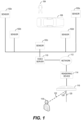
FIG. 1 illustrates a functional block diagram of an exemplary realistic point of view video system. The system shown inFIG. 1 includes several sensors,sensor 102a,sensor 102b,sensor 102c,sensor 102d, andsensor 102e (collectively hereinafter referred to as sensor 102). The sensor 102 may be a camera, a microphone, an infrared detector, or other device configured to capture information about a scene. The sensor 102 may be digital or analog. In some implementations, an analog recording may be converted to digital form directly by the sensor 102 or through post processing conversion (not shown). - Each sensor 102 is configured to capture the scene information from a capture position. A capture position includes a capture angle and a capture distance. The capture angle identifies a horizontal and vertical angle of the sensor 102 when the scene was captured by the sensor 102.
- As shown, the five sensors are arranged in a semi-circle around the scene. The scene shown in
FIG. 1 includes aperson 104 and acar 106. It will be understood that the scene may include other objects and subject matter. Depending on the location of the sensor 102, the amount of theperson 104 visible at the location changes. For example, thesensor 102a, thesensor 102b, and thesensor 102e may capture full views of theperson 104. Thesensor 102a and thesensor 102b will not be able to capture a view of the headlights of thecar 106. Thesensor 102c may be able to obtain a partial image of the person 102 with a portion of the person 102 being obstructed by thecar 106. Similarly, thesensor 102d may capture the top of the head of theperson 104 but the rest of theperson 104 may be obstructed by thecar 106. - Accordingly, various views of the scene will provide different details of the objects within the scene. The capture position at the time of capture is stored along with the image data. The capture position may be represented relative to the scene, relative to a configured "center" of the scene, and/or relative to other sensors used to capture the scene.
- The capture position and image information may be provided to a
video server 110. The capture position may be provided as an offset from a center view of the scene. In some implementations, the capture position may be provided as a relative value from the sensor to another sensor. - The capture position and image information may be transmitted electronically from the sensor 102 to the
video server 110. In some implementations, the information may be stored by an intermediary such as a digital memory (e.g., DVD, CD, Blu-ray, network storage location, etc.) and later loaded onto thevideo server 110. In some implementations, thevideo server 110 may not store all the information, but rather only a portion of the information needed to identify the video, the available versions, and locator information for the version (e.g., uniform resource locator (URL)). - Via a
network 112, arendering device 114 may request video content from thevideo server 110. The network may include one or more of a satellite network, local area network, wide area network, cellular network, peer-to-peer network and the like. Thenetwork 112 may be a public network (e.g., the Internet), or a private network (e.g., virtual private network (VPN)). The information can be transmitted via thenetwork 112 using appropriate and known network transmission protocols (e.g., TCP/IP). - The
rendering device 114 may be implemented as a set-top-box, a console, a computing device (e.g., laptop, desktop, smartphone), or the like. Therendering device 114 is coupled with adisplay 116. Thedisplay 116 may be implemented as a device configured to present video images such as a liquid crystal display, a cathode ray tube display, a plasma display, a touch screen display, or a light emitting diode display. Thedisplay 116 may be configured to present the video images in two or three dimensions. In some implementations, therendering device 114 may be integrated in thedisplay 116. - The
display 116 may be associated with acenter view position 120. Thecenter view position 120 generally refers to a position relative to thedisplay 116 whereby the viewer is perpendicular to thedisplay 116 and centered on the face of thedisplay 116. For example, if thedisplay 116 is a 20 inch square display, a point 10 inches from the left side of thedisplay 116 and 10 inches from the top of thedisplay 116 would correspond to the center of the face of thedisplay 116. - A
viewer 118 may not be watching thedisplay 116 from thecenter view position 120. The viewer may be located at an angle offset from the center view position. The angle may be referred to as aviewing angle 124. As shown inFIG. 1 , theviewing angle 124 is a two dimensional angle. It will be appreciated that theviewing angle 124 comprises a horizontal viewing and vertical viewing angle. - The
viewer 118 may also be located at a certain distance from the view. The distance may be referred to as aviewing distance 122. Using the position information of the viewer, such as theviewing angle 124 and/or theviewing distance 122, a realistic version of the scene may be provided which is realistic to the position of theviewer 118. -
FIG. 2 illustrates a functional block diagram of an exemplary portion of a realistic point of view video system. Therendering device 114 includes acontent selector 250. Thecontent selector 250 is configured to receive a selection of a piece of video content for display. For example, thecontent selector 250 may receive a signal from a remote control indicating a particular video for presentation. In some implementations, thedisplay 116 may receive the selection of content for display and provide this indication to thecontent selector 250. - The
rendering device 114 shown includes aposition detector 252. Theposition detector 252 is configured to determine the viewing positions of one or more viewers located proximate to thedisplay 116. In one implementation, theposition detector 252 may detect the location of a device such as a remote control and use this as the viewing position. In some implementations, theposition detector 252 may receive a signal from a device attached or associated with the viewer such as viewing glasses or a wearable beacon. Other sensors may be included to transmit one or more signals to theposition detector 252 such as a photodetector, a light source, a gyroscope, a global positioning system, or an antenna (e.g., wireless antenna). - In some implementations, the
position detector 252 may determine the viewing position based on image capture of the viewing area. In such implementations, theposition detector 252 may obtain calibrated distances and angles to known objects in the viewing area such as sofas, bookshelves, potted plants, exercise equipment, lighting or electrical fixtures, décor items, and the like. Based on these known objects, theposition detector 252 may periodically receive an image of the viewing area and determine the location of objects relative to the known objects. - Another image detection process including facial recognition may be used to determine viewing position information. For example, upon capturing an image of the viewing area from a reference point near the display, human faces may be identified. Based on characteristics of the identified human faces included in the image such as size, shadows, location of features (e.g., eyes, nose, and forehead), the viewing distance and/or angle may be determined.
- Other methods of determining the viewing position may be implemented without departing from the scope of the present disclosure.
- The
rendering device 114 shown also includes acontent requestor 254. Thecontent requestor 254 is configured to request the selected content. If therendering device 114 determines that the content source is configured to handle content requests including viewing position information, thecontent requestor 254 may include the detected viewing position information. Theposition detector 252 may be configured to detect the viewing position for more than one viewer. In some implementations, thecontent requestor 254 may transmit all the viewing positions in the content request. In some implementations, thecontent requestor 254 or theposition detector 252 may generate a composite viewing position for a plurality of viewers. For example, the viewing position may be an average of all detected viewing positions. - The content request may include an identifier for the selected content. The identifier may be a link (e.g., URL) to the content. The content request may include the viewing position information. The viewing position information may be included as a coordinate pair for two-dimensional positional information. The viewing position information may include three-dimensional positional information. Three-dimensional positional information may be represented in a variety of ways such as a Cartesian coordinate trio (e.g., X, Y, and Z), spherical coordinates, and/or cylindrical coordinates.
- The viewing position information may also include a relative point indicating the point of reference for the provided viewing position. Examples of relative points include the center of the display, the top of the display, and the bottom of the display. In some implementations, multiple viewing positions relative to multiple reference points may be provided in the content request.
- It will be appreciated that the more position information provided, the more accurately the position may be determined. Accordingly, the amount of position information included in the content request may be dynamically adjusted. The amount of position information may refer to the number of viewing position coordinates provided and/or the precision used to represent the position (e.g., number of decimal places). The adjustment may be based on the type of content (e.g., live versus recorded),
network 112 resources,video server 110 resources, andrendering device 114 resources. In some implementations, the content request may be included in a file such as an XML file. - The
content requestor 254 may transmit the content request via thenetwork 112 to thevideo server 110. - The
video server 110 may include animage data receiver 202. Theimage data receiver 202 is configured to receive the image data such as the video data. Theimage data receiver 202 may receive the actual picture information for the video. In some implementations, theimage data receiver 202 may receive only pointers (e.g., URLs) to the video data. For a given video presentation, theimage data receiver 202 may receive multiple views, each view corresponding to a sensor 102. Theimage data receiver 202 may store the received image data in animage data store 204. - A
request processor 206 receives the content request from thecontent requestor 254 via thenetwork 112. Therequest processor 206 is configured to determine if the selected content is included in theimage data store 204. If the selected content is identified in theimage data store 204, therequest processor 206 is further configured to determine if a version of the image data corresponding to the viewing position is available. - In some implementations, the
image data store 204 may include a version of the selected content captured by a sensor 102 at the specified viewing position. In some implementations, theimage data store 204 may not include a version from the specified viewing position. Therequest processor 206 obtains a tolerance value. The tolerance value identifies a viewing position deviation value. The viewing position deviation value indicates an acceptable difference between the specified viewing position and the viewing position of image data included in thedata store 204. For example, if the tolerance value is 5 and the specified viewing angle is 79 degrees, a version of the selected content captured from 75 degrees would be deemed acceptable. Using the same tolerance value of 5 and a viewing angle of 85 degrees, the version of the selected content captured at 75 degrees would not be deemed acceptable for presentation. - The tolerance value may be configured in the
video server 110. In some implementations, the tolerance value may be configured as part of the received image data. For example, certain content may be less sensitive to vertical viewing angle than horizontal viewing angles. The viewing position deviation tolerance for horizontal and vertical viewing angles are associated with the image data and stored in theimage data store 204. - The tolerance value may be included in the content request by, for example the
content requestor 254. In one implementation, thecontent requestor 254 may obtain the tolerance from a user configuration stored in memory of therendering device 114. - If image data captured at or within a threshold of the specified viewing angle is included in the
image data store 204, the image data is provided to astream generator 208 included in thevideo server 110. Thestream generator 208 is configured to generate a stream of image data suitable for transmission via thenetwork 112 to therendering device 114. - In some implementations, the specified viewing position may be between the capture positions for two versions of the selected content. In such a case, the
stream generator 208 is configured to generate a single composite stream which combines the two streams to provide an image data stream at the specified viewing position. In some implementations, the generation of the composite view may be referred to as interpolation. - In some implementations, the
video server 110 may be configured to provide the one or more views. Thestream generator 208 may be configured to transmit the image data corresponding to the two versions of the selected content to therendering device 114. In such implementations, therendering device 114 may be configured to further process the received views. Acontent renderer 256 included in therendering device 114 may be configured to generate the composite view from the provided streams. - The
content renderer 256 may also be configured to provide the image stream corresponding to the selected content at the specified viewing position for display. In addition to generating a composite stream and providing the final output stream, thecontent renderer 256 may also be configured to further enhance the content before final presentation. For example, thecontent renderer 256 may also consider theviewing distance 122 of theviewer 118. Based on theviewing distance 122, thecontent renderer 256 may zoom in on a portion of the selected content. - It will be understood that the system described in
FIG. 2 is a dynamic system. Accordingly, theposition detector 252 may be configured to periodically determine the position of theviewer 118 and re-select content and/or viewing angles. The period for determining the viewing position may be configured by the user at therendering device 114. The period may also be dynamically determined based on characteristics of therendering device 114 such as processor load, battery power, network bandwidth, network connectivity type (e.g., cellular, WiFi, Ethernet), and the like. -
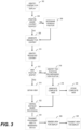
FIG. 3 illustrates a process flow diagram for an exemplary process of providing realistic point of view video. The process shown inFIG. 3 may be implemented in/by thevideo server 110 and/or therendering device 114. Atnode 302, content for display is identified. The identification may include receiving a selection from a remote control, an on-screen interface selection, according to a schedule, or the like. - At
decision node 304, a determination is made as to whether the content source for the identified content is position aware. A content source is position aware if the content source can receive viewing position information and provide one or more image streams based in part on the viewing position information. The determination may include transmitting a request to the content source for capability information. The capability information may be stored in a memory (e.g., cached). In some implementations, the content sources may be statically defined. In such implementations, the determination may include querying the static definitions for the characteristics of the identified content source. - If the content source is not position aware, at
node 306, a request for the content is generated without determining the view position. Returning todecision node 304, if the content source is a position aware content source, atnode 308 the position(s) of the viewer(s) is determined as discussed above. Atnode 306, the request for the content is generated including the viewing position information. - At
node 310, thevideo server 110 identifies the requested content. The identification may include querying theimage data store 204 for the requested content. Atdecision node 312, a determination is made as to whether the requested view position exists. If no view position was requested (e.g., when the content source is not position aware), the identified view is the default view position and the process continues tonode 314 as will be described. In a position aware content source, if the identified version of the content is at or within the tolerance of the requested view position, the process also continues tonode 314. - At
node 314, the identified view is obtained. Obtaining the identified view may include retrieving the image data for the requested content from theimage data store 204. Obtaining the identified view may include retrieving location information for the image data from theimage data store 204 and initiating a download of the image data. - Returning to
decision node 312, if the requested view position does not exist but the content source is position aware, atnode 316, two positions encompassing the requested view position are identified. For example, the requested view angle may be 75 degrees but the selected content was captured only in intervals of 10 degrees (e.g., 10, 20, 30, 40, 50, 60, 70, 80, and 90 degrees). In such an example, the versions captured at 70 and 80 degrees would encompass a requested view angle of 75 degrees. - At
node 318, a composite view is generated based on the identified encompassing views. To generate the composite view, image data from a portion of the first captured view position and a portion of the second captured view position at the same point in time are identified. The identified portions are then combined to generate the composite view. The combination may include averaging the image data between the two views, performing spatial or feature detection to identify the appropriate composite image information, interpolation based on the identified views, or other processes for generating image data from multiple sources. Some implementations may includenode 320. Atnode 320, the generated composite view may be stored in theimage data store 204. Position information associated with the generated composite view may also be stored for the generated composite view. It may be desirable in some systems to store the generated composite view as an eligible version of the scene for subsequent requests. The storing ofnode 320 may occur during or after the remaining processing shown inFIG. 3 . - At
node 322, the obtained or composite view may be further processed based on viewing distance. The viewing distance processing may include zooming in or out on a portion of the content based on the viewing distance included in the content request. For example, if the viewing distance corresponds to the distance of the capture device to the scene, no processing may be performed atnode 322. If the viewing distance corresponds to less than the distance of the capture device to the scene, atnode 322, the content may be zoomed in thereby excluding a peripheral portion of the view and enlarging the remaining portion of the view. Zooming in may include one or more of scaling and cropping of the view. The view distance based processing may be configurably enabled such as by a configuration value stored in thevideo server 110 or included in the content request. - The processing may be similarly configured to limit the amount of zooming for the device or for a particular content selection. For example, the
video server 110 may include a minimum and maximum zoom. If the view distance included in the content request is less than the minimum zoom, no zoom processing is performed. If the view distance in the content request is greater than the maximum zoom, the processing may perform zooming up to the maximum rather than according to the identified view distance. - At
node 324, a view which includes content selected and processed based on the content request is transmitted to therendering device 114. The transmission may be a single stream of the view. In some implementations, the view may be divided into smaller data packets. In such implementations, the transmission may include sending all or a portion of the packets. The transmission may be wired or wireless as discussed above. - At
node 326, the view is rendered for display. The rendering may include additional color correction, formatting, scaling, and the like to allow the view to be displayed on the target display. - At
node 328, the rendered view is transmitted to thedisplay 116 for presentation. The transmission may be a single stream of the view. In some implementations, the view may be divided into smaller data packets. In such implementations, the transmission may include sending all or a portion of the packets. The transmission may be wired or wireless as discussed above. In some implementations, the rendered view may be stored in a memory accessible by thedisplay 116. At the time of presentation, the rendered view is retrieved from the memory by thedisplay 116 for presentation. - The process described in
FIG. 3 includes generating the composite view at thevideo server 110. In some implementations, the generation of the composite view may be performed by therendering device 114 as described above. Similarly, the viewing distance based processing was described inFIG. 3 as occurring at thevideo server 110. In some implementations, it may be desirable to perform the viewing distance based processing at therendering device 114 as described above. -
FIG. 4 illustrates a process flow diagram for an exemplary process of providing realistic video. The process may be implemented in whole or in part by the devices described herein. For example, the process may be implemented by/in avideo server 110 or the device shown inFIG. 5 below. - At
node 402, multiple views of a scene for the video are obtained. Each view includes a capture position. The capture position, as discussed above, includes information identifying the location of the sensor when the associated view was captured. The location information includes a horizontal capture angle, a vertical capture angle, and may also include distance information. The location information may be specified relative to a fixed point such as a center of the scene. The location information may be specified in relative terms, such as relative to another sensor or an object in the scene. The views may be obtained in real-time (e.g., live video) from the sensor (e.g., camera), or via a recorded image store. - At
node 404, a request for the scene is received. The request includes a viewing position. The viewing position, as discussed above, includes information identifying the location of the viewer of the requested scene. The location information includes a horizontal viewing angle, a vertical capture angle, and may also include distance information. The location information may be specified relative to a fixed viewing point such as the center of the display. The location information may be specified in relative terms. - At
node 406, one or more views of the scene are identified based on a comparison of the viewing position with the capture position of each view. For example, a query of the image store may be performed specifying the scene and the requested viewing position. As discussed above, multiple views may be selected. For example, if the requested viewing angle is not available, two views bounding the requested viewing angle are identified. - At
node 408, an output view is generated based on the identified views and the viewing position. The generation may include interpolating the output view when multiple views are identified. The generation may include zooming in on the identified view based on a viewing distance. In implementations where multiple views are identified, the zooming may be performed on each identified view or on the composite view. -
FIG. 5 illustrates a functional block diagram of a device for providing realistic video. Those skilled in the art will appreciate that a device for providing realistic video may have more components than thesimplified device 500 shown inFIG. 5 . Thedevice 500 shown inFIG. 5 includes only those components useful for describing some prominent features of implementations with the scope of the claims. Thedevice 500 includes aview capture circuit 502, arequest receiver 504, aview selector 506, and aview generator 508. - The
view capture circuit 502 is configured to obtain multiple views of a scene, each view having a capture position. Theview capture circuit 502 may include one or more of a sensor, a camera, a memory, a processor, a network interface, and a transceiver. In some implementations, means for obtaining multiple views of a scene include theview capture circuit 502. - The
request receiver 504 is configured to receive a request for the scene, the request including a viewing position. Therequest receiver 504 may include one or more of an antenna, a signal processor, a memory, a request parser, and a network interface. In some implementations, means for receiving a request for the scene include therequest receiver 504. - The
view selector 506 is configured to identify one or more views of the scene based on a comparison of the viewing position and the capture position of each view. Theview selector 506 may include one or more of a comparator, a processor, and a memory. In some implementations, means for identifying one or more views of the scene include theview selector 506. - The
view generator 508 is configured to generate an output view based on the identified views and the viewing position. Theview generator 508 may include one or more of a view interpolator, an estimation unit, an encoding unit, a compression unit, a processor, and a memory. In some implementations, means for generating an output view include theview generator 508. -
FIG. 6 illustrates a process flow diagram for an exemplary process of obtaining realistic video. The process may be implemented in whole or in part by the devices described herein. For example, the process may be implemented by/in arendering device 114 or the device shown inFIG. 7 below. - At
node 602, a content request including a content selection and a viewing position is transmitted. The content request may be transmitted to a video server. The viewing position may include at least one of a viewing angle and a viewing distance of a viewer of the selected content. The viewing angle includes a horizontal and vertical viewing angle. - At
node 604, one or more view of the requested content are received. Each received view includes capture position information. The capture position information may identify a capture angle and/or distance for the view. - At
node 606, an output view is generated based on the received views and the viewing position. In some implementations, this may include interpolating the output view based on two or more received views. The generating may also include zooming in on the view based on a viewing distance. -
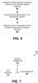
FIG. 7 illustrates a functional block diagram of a device for obtaining realistic video. Those skilled in the art will appreciate that a device for obtaining realistic video may have more components than thesimplified device 700 shown inFIG. 7 . Thedevice 700 shown inFIG. 7 includes only those components useful for describing some prominent features of implementations with the scope of the claims. Thedevice 700 includes arequest transmitter 702, aview receiver 704, and aview generator 706. - The
request transmitter 702 is configured to transmit a content request including a content selection and a viewing position. Therequest transmitter 702 may include one or more of an antenna, a transmitter, a power source, an amplifier, a processor, a signal generator, and a memory. In some implementations, means for transmitting a content request includes therequest transmitter 702. - The
view receiver 704 is configured to receive one or more views of the requested content. Theview receiver 704 may include one or more of a receiver, an antenna, a signal processor, a network interface, a memory, and a multiplexor. In some implementations, means for receiving one or more views of the requested content includes theview receiver 704. - The
view generator 706 is configured to generate an output view based on the received views and the viewing position. Theview generator 706 may include one or more of a view interpolator, an estimation unit, an encoding unit, a compression unit, a processor, and a memory. In some implementations, means for generating an output view include theview generator 706. - As used herein, the terms "determine" or "determining" encompass a wide variety of actions. For example, "determining" may include calculating, computing, processing, deriving, investigating, looking up (e.g., looking up in a table, a database or another data structure), ascertaining and the like. Also, "determining" may include receiving (e.g., receiving information), accessing (e.g., accessing data in a memory) and the like. Also, "determining" may include resolving, selecting, choosing, establishing and the like.
- As used herein, the terms "provide" or "providing" encompass a wide variety of actions. For example, "providing" may include storing a value in a location for subsequent retrieval, transmitting a value directly to the recipient, transmitting or storing a reference to a value, and the like. "Providing" may also include encoding, decoding, encrypting, decrypting, validating, verifying, and the like.
- As used herein, a phrase referring to "at least one of' a list of items refers to any combination of those items, including single members. As an example, "at least one of: a, b, or c" is intended to cover: a, b, c, a-b, a-c, b-c, and a-b-c.
- The various operations of methods described above may be performed by any suitable means capable of performing the operations, such as various hardware and/or software component(s), circuits, and/or module(s). Generally, any operations illustrated in the Figures may be performed by corresponding functional means capable of performing the operations.
- The various illustrative logical blocks, modules and circuits described in connection with the present disclosure may be implemented or performed with a general purpose processor, a digital signal processor (DSP), an application specific integrated circuit (ASIC), a field programmable gate array signal (FPGA) or other programmable logic device (PLD), discrete gate or transistor logic, discrete hardware components or any combination thereof designed to perform the functions described herein. A general purpose processor may be a microprocessor, but in the alternative, the processor may be any commercially available processor, controller, microcontroller or state machine. A processor may also be implemented as a combination of computing devices, e.g., a combination of a DSP and a microprocessor, a plurality of microprocessors, one or more microprocessors in conjunction with a DSP core, or any other such configuration.
- In one or more aspects, the functions described may be implemented in hardware, software, firmware, or any combination thereof. If implemented in software, the functions may be stored on or transmitted over as one or more instructions or code on a computer-readable medium. Computer-readable media includes both computer storage media and communication media including any medium that facilitates transfer of a computer program from one place to another. A storage media may be any available media that can be accessed by a computer. By way of example, and not limitation, such computer-readable media can comprise RAM, ROM, EEPROM, CD-ROM or other optical disk storage, magnetic disk storage or other magnetic storage devices, or any other medium that can be used to carry or store desired program code in the form of instructions or data structures and that can be accessed by a computer. Also, any connection is properly termed a computer-readable medium. For example, if the software is transmitted from a website, server, or other remote source using a coaxial cable, fiber optic cable, twisted pair, digital subscriber line (DSL), or wireless technologies such as infrared, radio, and microwave, then the coaxial cable, fiber optic cable, twisted pair, DSL, or wireless technologies such as infrared, radio, and microwave are included in the definition of medium. Disk and disc, as used herein, includes compact disc (CD), laser disc, optical disc, digital versatile disc (DVD), floppy disk and blu-ray disc where disks usually reproduce data magnetically, while discs reproduce data optically with lasers. Thus, in some aspects computer readable medium may comprise non-transitory computer readable medium (e.g., tangible media). In addition, in some aspects computer readable medium may comprise transitory computer readable medium (e.g., a signal). Combinations of the above should also be included within the scope of computer-readable media.
- The methods disclosed herein comprise one or more steps or actions for achieving the described method. The method steps and/or actions may be interchanged with one another without departing from the scope of the claims. In other words, unless a specific order of steps or actions is specified, the order and/or use of specific steps and/or actions may be modified without departing from the scope of the claims.
- The functions described may be implemented in hardware, software, firmware or any combination thereof. If implemented in software, the functions may be stored as one or more instructions on a computer-readable medium. A storage media may be any available media that can be accessed by a computer. By way of example, and not limitation, such computer-readable media can comprise RAM, ROM, EEPROM, CD-ROM or other optical disk storage, magnetic disk storage or other magnetic storage devices, or any other medium that can be used to carry or store desired program code in the form of instructions or data structures and that can be accessed by a computer. Disk and disc, as used herein, include compact disc (CD), laser disc, optical disc, digital versatile disc (DVD), floppy disk, and Blu-ray® disc where disks usually reproduce data magnetically, while discs reproduce data optically with lasers.
- Thus, certain aspects may comprise a computer program product for performing the operations presented herein. For example, such a computer program product may comprise a computer readable medium having instructions stored (and/or encoded) thereon, the instructions being executable by one or more processors to perform the operations described herein. For certain aspects, the computer program product may include packaging material.
- Software or instructions may also be transmitted over a transmission medium. For example, if the software is transmitted from a website, server, or other remote source using a coaxial cable, fiber optic cable, twisted pair, digital subscriber line (DSL), or wireless technologies such as infrared, radio, and microwave, then the coaxial cable, fiber optic cable, twisted pair, DSL, or wireless technologies such as infrared, radio, and microwave are included in the definition of transmission medium.
- Further, it should be appreciated that modules and/or other appropriate means for performing the methods and techniques described herein can be downloaded and/or otherwise obtained by an encoding device and/or decoding device as applicable. For example, such a device can be coupled to a server to facilitate the transfer of means for performing the methods described herein. Alternatively, various methods described herein can be provided via storage means (e.g., RAM, ROM, a physical storage medium such as a compact disc (CD) or floppy disk, etc.), such that a user terminal and/or base station can obtain the various methods upon coupling or providing the storage means to the device. Moreover, any other suitable technique for providing the methods and techniques described herein to a device can be utilized.
- It is to be understood that the claims are not limited to the precise configuration and components illustrated above. Various modifications, changes and variations may be made in the arrangement, operation and details of the methods and apparatus described above without departing from the scope of the claims.
- While the foregoing is directed to aspects of the present disclosure, other and further aspects of the disclosure may be devised without departing from the basic scope thereof, and the scope thereof is determined by the claims that follow.
Claims (8)
- A method of providing realistic video, the method comprising:receiving (402), at an image data receiver (202), image data comprising multiple views of a scene, each view having a capture position identifying a capture angle and a capture distance of a sensor capturing the view, the capture angle comprising a horizontal capture angle and a vertical capture angle;storing the image data with the respective capture positions in an image data store (204);receiving (404), at a request processor (206), a content request for the scene that identifies selected content, the content request including a viewing position, wherein the viewing position includes a viewing angle of a viewer of the video, the viewing angle comprising a horizontal viewing angle and a vertical viewing angle;determining, at the request processor, whether the selected content is included in the image data store;wherein a first viewing position deviation tolerance value and a second viewing position deviation tolerance value, based on image content, are associated with the image data and are stored in the image data store, the first tolerance value indicating an acceptable difference between a horizontal viewing angle and a horizontal capture angle of a view of the multiple views of the scene, the second tolerance value indicating an acceptable difference between a vertical viewing angle and a vertical capture angle of a view of the multiple views of the scene;determining if the viewing angle is at or within the first and second tolerance values of each view of the multiple views of the scene;if the viewing angle is at or within the first and second tolerance values of a single view of the multiple views of the scene, generating an output view using the single view;if the viewing angle is outside the first or second tolerance value of each view of the multiple views of the scene, identifying (406) at least two of the multiple views of the scene bounding the requested viewing angle based on a comparison of the viewing angle and the capture angle of each view; andgenerating (408) an output view comprising a composite view of the identified views based on the viewing position.
- The method of Claim 1, wherein the viewing position also includes a viewing distance of a viewer of the video.
- The method of Claim 1, wherein receiving the request comprises periodically receiving requests for the scene, each request including a viewing position.
- The method of Claim 1, wherein generating an output view comprising a composite view comprises generating an interpolated view based on a first view and a second view of the multiple views.
- The method of Claim 1, wherein generating the output view comprises scaling the output view based at least in part on the viewing position.
- The method of Claim 1, wherein generating the output view comprises cropping the output view based at least in part on the viewing position.
- A device (110, 114) for providing realistic video, the device comprising:means for receiving), at an image data receiver (202), image data comprising multiple views of a scene, each view having a capture position identifying a capture angle and a capture distance of a sensor capturing the view, the capture angle comprising a horizontal capture angle and a vertical capture angle;means for storing the image data with the respective capture positions in an image data store (204);means for receiving, at a request processor (206), a content request for the scene that identifies selected content, the content request including a viewing position, wherein the viewing position includes a viewing angle of a viewer of the video, the viewing angle comprising a horizontal viewing angle and a vertical viewing angle;means for determining, at the request processor, whether the selected content is included in the image data store;wherein a first viewing position deviation tolerance value and a second viewing position deviation tolerance value, based on image content, are associated with the image data and are stored in the image data store, the first tolerance value indicating an acceptable difference between a horizontal viewing angle and a horizontal capture angle of a view of the multiple views of the scene, the second tolerance value indicating an acceptable difference between a vertical viewing angle and a vertical capture angle of a view of the multiple views of the scene;means for determining if the viewing angle is at or within the first and second tolerance value of each view of the multiple views of the scene;means for generating an output view using the single view if the viewing angle is at or within the first and second tolerance values of a single view of the multiple views of the scene;means for identifying at least two of the multiple views of the scene bounding the requested viewing angle based on a comparison of the viewing position and the capture position of each view if the viewing angle is outside the first or second tolerance value of each view of the multiple views of the scene; andmeans for generating an output view comprising a composite view of the identified views based on the viewing position if the viewing angle is outside the tolerance value of each view of the multiple views of the scene.
- A computer-readable storage medium comprising instructions executable by a processor of a device, the instructions causing the device to undertake the method of any of claims 1 to 6.
Applications Claiming Priority (2)
| Application Number | Priority Date | Filing Date | Title |
|---|---|---|---|
| US13/718,957 US10116911B2 (en) | 2012-12-18 | 2012-12-18 | Realistic point of view video method and apparatus |
| PCT/US2013/071304 WO2014099251A1 (en) | 2012-12-18 | 2013-11-21 | Realistic point of view video method and apparatus |
Publications (2)
| Publication Number | Publication Date |
|---|---|
| EP2936806A1 EP2936806A1 (en) | 2015-10-28 |
| EP2936806B1 true EP2936806B1 (en) | 2023-03-29 |
Family
ID=49759571
Family Applications (1)
| Application Number | Title | Priority Date | Filing Date |
|---|---|---|---|
| EP13803360.0A Active EP2936806B1 (en) | 2012-12-18 | 2013-11-21 | Realistic point of view video method and apparatus |
Country Status (5)
| Country | Link |
|---|---|
| US (1) | US10116911B2 (en) |
| EP (1) | EP2936806B1 (en) |
| JP (1) | JP2016507929A (en) |
| CN (1) | CN104854861B (en) |
| WO (1) | WO2014099251A1 (en) |
Families Citing this family (4)
| Publication number | Priority date | Publication date | Assignee | Title |
|---|---|---|---|---|
| WO2016140986A1 (en) * | 2015-03-01 | 2016-09-09 | Nextvr Inc. | Methods and apparatus for supporting content generation, transmission and/or playback |
| KR20160135660A (en) * | 2015-05-18 | 2016-11-28 | 한국전자통신연구원 | Method and apparatus for providing 3-dimension image to head mount display |
| EP3151554A1 (en) | 2015-09-30 | 2017-04-05 | Calay Venture S.a.r.l. | Presence camera |
| US10110802B2 (en) * | 2016-12-30 | 2018-10-23 | Axis Ab | Historical gaze heat map for a video stream |
Citations (5)
| Publication number | Priority date | Publication date | Assignee | Title |
|---|---|---|---|---|
| US20080178232A1 (en) * | 2007-01-18 | 2008-07-24 | Verizon Data Services Inc. | Method and apparatus for providing user control of video views |
| JP2008217243A (en) * | 2007-03-01 | 2008-09-18 | Mitsubishi Electric Corp | Image creation device |
| US20110254927A1 (en) * | 2010-04-16 | 2011-10-20 | Canon Kabushiki Kaisha | Image processing apparatus and method |
| US20120062556A1 (en) * | 2010-09-13 | 2012-03-15 | Sumihiko Yamamoto | Three-dimensional image display apparatus, three-dimensional image processor, three-dimensional image display method, and computer program product |
| US20120293638A1 (en) * | 2011-05-19 | 2012-11-22 | Samsung Electronics Co., Ltd. | Apparatus and method for providing 3d content |
Family Cites Families (25)
| Publication number | Priority date | Publication date | Assignee | Title |
|---|---|---|---|---|
| US5495576A (en) * | 1993-01-11 | 1996-02-27 | Ritchey; Kurtis J. | Panoramic image based virtual reality/telepresence audio-visual system and method |
| US5729471A (en) * | 1995-03-31 | 1998-03-17 | The Regents Of The University Of California | Machine dynamic selection of one video camera/image of a scene from multiple video cameras/images of the scene in accordance with a particular perspective on the scene, an object in the scene, or an event in the scene |
| JPH09200715A (en) | 1996-01-19 | 1997-07-31 | Canon Inc | Equipment, method and system for communication |
| US6573912B1 (en) | 2000-11-07 | 2003-06-03 | Zaxel Systems, Inc. | Internet system for virtual telepresence |
| JP4539015B2 (en) | 2002-12-11 | 2010-09-08 | ソニー株式会社 | Image communication apparatus, image communication method, and computer program |
| US9030532B2 (en) * | 2004-08-19 | 2015-05-12 | Microsoft Technology Licensing, Llc | Stereoscopic image display |
| CN1984295A (en) | 2005-12-15 | 2007-06-20 | 皇家飞利浦电子股份有限公司 | Method and unit for processing video transmission stream |
| US10063848B2 (en) * | 2007-08-24 | 2018-08-28 | John G. Posa | Perspective altering display system |
| CN101472190B (en) | 2007-12-28 | 2013-01-23 | 华为终端有限公司 | Multi-visual angle filming and image processing apparatus and system |
| JP2012501506A (en) * | 2008-08-31 | 2012-01-19 | ミツビシ エレクトリック ビジュアル ソリューションズ アメリカ, インコーポレイテッド | Conversion of 3D video content that matches the viewer position |
| US8477175B2 (en) | 2009-03-09 | 2013-07-02 | Cisco Technology, Inc. | System and method for providing three dimensional imaging in a network environment |
| US20100259595A1 (en) * | 2009-04-10 | 2010-10-14 | Nokia Corporation | Methods and Apparatuses for Efficient Streaming of Free View Point Video |
| US8320623B2 (en) * | 2009-06-17 | 2012-11-27 | Lc Technologies, Inc. | Systems and methods for 3-D target location |
| CN102484733B (en) * | 2009-08-25 | 2015-11-25 | 杜比实验室特许公司 | 3d display system |
| US8762846B2 (en) * | 2009-11-16 | 2014-06-24 | Broadcom Corporation | Method and system for adaptive viewport for a mobile device based on viewing angle |
| KR101763592B1 (en) | 2010-08-16 | 2017-08-01 | 엘지전자 주식회사 | Method for processing image of display system outputting 3 dimensional contents and display system enabling of the method |
| US9167289B2 (en) * | 2010-09-02 | 2015-10-20 | Verizon Patent And Licensing Inc. | Perspective display systems and methods |
| JP2012094990A (en) | 2010-10-25 | 2012-05-17 | Duse Technologies Co Ltd | Image display system associating with view point |
| US8842168B2 (en) * | 2010-10-29 | 2014-09-23 | Sony Corporation | Multi-view video and still 3D capture system |
| US20120162384A1 (en) * | 2010-12-22 | 2012-06-28 | Vesely Michael A | Three-Dimensional Collaboration |
| JP5067477B2 (en) | 2010-12-28 | 2012-11-07 | カシオ計算機株式会社 | Imaging parameter acquisition apparatus, imaging parameter acquisition method, and program |
| US20120200676A1 (en) | 2011-02-08 | 2012-08-09 | Microsoft Corporation | Three-Dimensional Display with Motion Parallax |
| JP5912680B2 (en) * | 2011-03-11 | 2016-04-27 | 株式会社半導体エネルギー研究所 | Display device and driving method of display device |
| JP2012204852A (en) | 2011-03-23 | 2012-10-22 | Sony Corp | Image processing apparatus and method, and program |
| EP2795919A4 (en) * | 2011-12-23 | 2015-11-11 | Nokia Technologies Oy | Aligning videos representing different viewpoints |
-
2012
- 2012-12-18 US US13/718,957 patent/US10116911B2/en active Active
-
2013
- 2013-11-21 CN CN201380065460.6A patent/CN104854861B/en active Active
- 2013-11-21 WO PCT/US2013/071304 patent/WO2014099251A1/en active Application Filing
- 2013-11-21 JP JP2015547380A patent/JP2016507929A/en not_active Ceased
- 2013-11-21 EP EP13803360.0A patent/EP2936806B1/en active Active
Patent Citations (5)
| Publication number | Priority date | Publication date | Assignee | Title |
|---|---|---|---|---|
| US20080178232A1 (en) * | 2007-01-18 | 2008-07-24 | Verizon Data Services Inc. | Method and apparatus for providing user control of video views |
| JP2008217243A (en) * | 2007-03-01 | 2008-09-18 | Mitsubishi Electric Corp | Image creation device |
| US20110254927A1 (en) * | 2010-04-16 | 2011-10-20 | Canon Kabushiki Kaisha | Image processing apparatus and method |
| US20120062556A1 (en) * | 2010-09-13 | 2012-03-15 | Sumihiko Yamamoto | Three-dimensional image display apparatus, three-dimensional image processor, three-dimensional image display method, and computer program product |
| US20120293638A1 (en) * | 2011-05-19 | 2012-11-22 | Samsung Electronics Co., Ltd. | Apparatus and method for providing 3d content |
Also Published As
| Publication number | Publication date |
|---|---|
| JP2016507929A (en) | 2016-03-10 |
| CN104854861B (en) | 2017-03-15 |
| CN104854861A (en) | 2015-08-19 |
| WO2014099251A1 (en) | 2014-06-26 |
| US10116911B2 (en) | 2018-10-30 |
| EP2936806A1 (en) | 2015-10-28 |
| US20140168359A1 (en) | 2014-06-19 |
Similar Documents
| Publication | Publication Date | Title |
|---|---|---|
| US11960639B2 (en) | Virtual 3D methods, systems and software | |
| US10540818B2 (en) | Stereo image generation and interactive playback | |
| US9965026B2 (en) | Interactive video display method, device, and system | |
| US10474227B2 (en) | Generation of virtual reality with 6 degrees of freedom from limited viewer data | |
| US11653065B2 (en) | Content based stream splitting of video data | |
| JP6131950B2 (en) | Information processing apparatus, information processing method, and program | |
| CN104641633B (en) | System and method for combining the data from multiple depth cameras | |
| US20190371073A1 (en) | System and method for augmented reality content delivery in pre-captured environments | |
| US9846960B2 (en) | Automated camera array calibration | |
| CN108154058B (en) | Graphic code display and position area determination method and device | |
| CN109600674A (en) | The client-based adaptive streaming of non-linear media transmits | |
| US11882267B2 (en) | Adapting video images for wearable devices | |
| US20130141550A1 (en) | Method, apparatus and computer program for selecting a stereoscopic imaging viewpoint pair | |
| JP2019062390A (en) | Information processing apparatus, information providing apparatus, control method, and program | |
| EP2936806B1 (en) | Realistic point of view video method and apparatus | |
| CN111869222B (en) | HTTP-based DASH client network element, method and medium | |
| US20180329602A1 (en) | Vantage generation and interactive playback | |
| KR20200065730A (en) | Method and apparatus for providing free viewpoint video | |
| KR102001255B1 (en) | Coordinated stereo image acquisition and viewing system | |
| CN116848840A (en) | Multi-view video streaming | |
| TW202339495A (en) | Presentation of multi-view video data | |
| JP2016046731A (en) | Video presentation device and program |
Legal Events
| Date | Code | Title | Description |
|---|---|---|---|
| PUAI | Public reference made under article 153(3) epc to a published international application that has entered the european phase |
Free format text: ORIGINAL CODE: 0009012 |
|
| 17P | Request for examination filed |
Effective date: 20150708 |
|
| AK | Designated contracting states |
Kind code of ref document: A1 Designated state(s): AL AT BE BG CH CY CZ DE DK EE ES FI FR GB GR HR HU IE IS IT LI LT LU LV MC MK MT NL NO PL PT RO RS SE SI SK SM TR |
|
| AX | Request for extension of the european patent |
Extension state: BA ME |
|
| DAX | Request for extension of the european patent (deleted) | ||
| STAA | Information on the status of an ep patent application or granted ep patent |
Free format text: STATUS: EXAMINATION IS IN PROGRESS |
|
| 17Q | First examination report despatched |
Effective date: 20191009 |
|
| STAA | Information on the status of an ep patent application or granted ep patent |
Free format text: STATUS: EXAMINATION IS IN PROGRESS |
|
| STAA | Information on the status of an ep patent application or granted ep patent |
Free format text: STATUS: EXAMINATION IS IN PROGRESS |
|
| REG | Reference to a national code |
Ref country code: DE Ref legal event code: R079 Ref document number: 602013083524 Country of ref document: DE Free format text: PREVIOUS MAIN CLASS: H04N0013000000 Ipc: H04N0013117000 |
|
| GRAP | Despatch of communication of intention to grant a patent |
Free format text: ORIGINAL CODE: EPIDOSNIGR1 |
|
| STAA | Information on the status of an ep patent application or granted ep patent |
Free format text: STATUS: GRANT OF PATENT IS INTENDED |
|
| RIC1 | Information provided on ipc code assigned before grant |
Ipc: H04N 21/6587 20110101ALI20220928BHEP Ipc: H04N 21/4728 20110101ALI20220928BHEP Ipc: H04N 13/178 20180101ALI20220928BHEP Ipc: H04N 21/218 20110101ALI20220928BHEP Ipc: H04N 13/117 20180101AFI20220928BHEP |
|
| INTG | Intention to grant announced |
Effective date: 20221012 |
|
| RAP3 | Party data changed (applicant data changed or rights of an application transferred) |
Owner name: QUALCOMM INCORPORATED |
|
| GRAS | Grant fee paid |
Free format text: ORIGINAL CODE: EPIDOSNIGR3 |
|
| GRAA | (expected) grant |
Free format text: ORIGINAL CODE: 0009210 |
|
| STAA | Information on the status of an ep patent application or granted ep patent |
Free format text: STATUS: THE PATENT HAS BEEN GRANTED |
|
| AK | Designated contracting states |
Kind code of ref document: B1 Designated state(s): AL AT BE BG CH CY CZ DE DK EE ES FI FR GB GR HR HU IE IS IT LI LT LU LV MC MK MT NL NO PL PT RO RS SE SI SK SM TR |
|
| REG | Reference to a national code |
Ref country code: GB Ref legal event code: FG4D |
|
| REG | Reference to a national code |
Ref country code: CH Ref legal event code: EP |
|
| REG | Reference to a national code |
Ref country code: DE Ref legal event code: R096 Ref document number: 602013083524 Country of ref document: DE |
|
| REG | Reference to a national code |
Ref country code: AT Ref legal event code: REF Ref document number: 1557474 Country of ref document: AT Kind code of ref document: T Effective date: 20230415 |
|
| REG | Reference to a national code |
Ref country code: IE Ref legal event code: FG4D |
|
| REG | Reference to a national code |
Ref country code: LT Ref legal event code: MG9D |
|
| PG25 | Lapsed in a contracting state [announced via postgrant information from national office to epo] |
Ref country code: RS Free format text: LAPSE BECAUSE OF FAILURE TO SUBMIT A TRANSLATION OF THE DESCRIPTION OR TO PAY THE FEE WITHIN THE PRESCRIBED TIME-LIMIT Effective date: 20230329 Ref country code: NO Free format text: LAPSE BECAUSE OF FAILURE TO SUBMIT A TRANSLATION OF THE DESCRIPTION OR TO PAY THE FEE WITHIN THE PRESCRIBED TIME-LIMIT Effective date: 20230629 Ref country code: LV Free format text: LAPSE BECAUSE OF FAILURE TO SUBMIT A TRANSLATION OF THE DESCRIPTION OR TO PAY THE FEE WITHIN THE PRESCRIBED TIME-LIMIT Effective date: 20230329 Ref country code: LT Free format text: LAPSE BECAUSE OF FAILURE TO SUBMIT A TRANSLATION OF THE DESCRIPTION OR TO PAY THE FEE WITHIN THE PRESCRIBED TIME-LIMIT Effective date: 20230329 Ref country code: HR Free format text: LAPSE BECAUSE OF FAILURE TO SUBMIT A TRANSLATION OF THE DESCRIPTION OR TO PAY THE FEE WITHIN THE PRESCRIBED TIME-LIMIT Effective date: 20230329 |
|
| REG | Reference to a national code |
Ref country code: NL Ref legal event code: MP Effective date: 20230329 |
|
| REG | Reference to a national code |
Ref country code: AT Ref legal event code: MK05 Ref document number: 1557474 Country of ref document: AT Kind code of ref document: T Effective date: 20230329 |
|
| PG25 | Lapsed in a contracting state [announced via postgrant information from national office to epo] |
Ref country code: SE Free format text: LAPSE BECAUSE OF FAILURE TO SUBMIT A TRANSLATION OF THE DESCRIPTION OR TO PAY THE FEE WITHIN THE PRESCRIBED TIME-LIMIT Effective date: 20230329 Ref country code: NL Free format text: LAPSE BECAUSE OF FAILURE TO SUBMIT A TRANSLATION OF THE DESCRIPTION OR TO PAY THE FEE WITHIN THE PRESCRIBED TIME-LIMIT Effective date: 20230329 Ref country code: GR Free format text: LAPSE BECAUSE OF FAILURE TO SUBMIT A TRANSLATION OF THE DESCRIPTION OR TO PAY THE FEE WITHIN THE PRESCRIBED TIME-LIMIT Effective date: 20230630 Ref country code: FI Free format text: LAPSE BECAUSE OF FAILURE TO SUBMIT A TRANSLATION OF THE DESCRIPTION OR TO PAY THE FEE WITHIN THE PRESCRIBED TIME-LIMIT Effective date: 20230329 |
|
| PG25 | Lapsed in a contracting state [announced via postgrant information from national office to epo] |
Ref country code: SM Free format text: LAPSE BECAUSE OF FAILURE TO SUBMIT A TRANSLATION OF THE DESCRIPTION OR TO PAY THE FEE WITHIN THE PRESCRIBED TIME-LIMIT Effective date: 20230329 Ref country code: RO Free format text: LAPSE BECAUSE OF FAILURE TO SUBMIT A TRANSLATION OF THE DESCRIPTION OR TO PAY THE FEE WITHIN THE PRESCRIBED TIME-LIMIT Effective date: 20230329 Ref country code: PT Free format text: LAPSE BECAUSE OF FAILURE TO SUBMIT A TRANSLATION OF THE DESCRIPTION OR TO PAY THE FEE WITHIN THE PRESCRIBED TIME-LIMIT Effective date: 20230731 Ref country code: ES Free format text: LAPSE BECAUSE OF FAILURE TO SUBMIT A TRANSLATION OF THE DESCRIPTION OR TO PAY THE FEE WITHIN THE PRESCRIBED TIME-LIMIT Effective date: 20230329 Ref country code: EE Free format text: LAPSE BECAUSE OF FAILURE TO SUBMIT A TRANSLATION OF THE DESCRIPTION OR TO PAY THE FEE WITHIN THE PRESCRIBED TIME-LIMIT Effective date: 20230329 Ref country code: AT Free format text: LAPSE BECAUSE OF FAILURE TO SUBMIT A TRANSLATION OF THE DESCRIPTION OR TO PAY THE FEE WITHIN THE PRESCRIBED TIME-LIMIT Effective date: 20230329 |
|
| PG25 | Lapsed in a contracting state [announced via postgrant information from national office to epo] |
Ref country code: SK Free format text: LAPSE BECAUSE OF FAILURE TO SUBMIT A TRANSLATION OF THE DESCRIPTION OR TO PAY THE FEE WITHIN THE PRESCRIBED TIME-LIMIT Effective date: 20230329 Ref country code: PL Free format text: LAPSE BECAUSE OF FAILURE TO SUBMIT A TRANSLATION OF THE DESCRIPTION OR TO PAY THE FEE WITHIN THE PRESCRIBED TIME-LIMIT Effective date: 20230329 Ref country code: IS Free format text: LAPSE BECAUSE OF FAILURE TO SUBMIT A TRANSLATION OF THE DESCRIPTION OR TO PAY THE FEE WITHIN THE PRESCRIBED TIME-LIMIT Effective date: 20230729 |
|
| REG | Reference to a national code |
Ref country code: DE Ref legal event code: R097 Ref document number: 602013083524 Country of ref document: DE |
|
| PGFP | Annual fee paid to national office [announced via postgrant information from national office to epo] |
Ref country code: GB Payment date: 20231013 Year of fee payment: 11 |
|
| PG25 | Lapsed in a contracting state [announced via postgrant information from national office to epo] |
Ref country code: DK Free format text: LAPSE BECAUSE OF FAILURE TO SUBMIT A TRANSLATION OF THE DESCRIPTION OR TO PAY THE FEE WITHIN THE PRESCRIBED TIME-LIMIT Effective date: 20230329 Ref country code: CZ Free format text: LAPSE BECAUSE OF FAILURE TO SUBMIT A TRANSLATION OF THE DESCRIPTION OR TO PAY THE FEE WITHIN THE PRESCRIBED TIME-LIMIT Effective date: 20230329 |
|
| PGFP | Annual fee paid to national office [announced via postgrant information from national office to epo] |
Ref country code: FR Payment date: 20231010 Year of fee payment: 11 Ref country code: DE Payment date: 20231010 Year of fee payment: 11 |
|
| PLBE | No opposition filed within time limit |
Free format text: ORIGINAL CODE: 0009261 |
|
| STAA | Information on the status of an ep patent application or granted ep patent |
Free format text: STATUS: NO OPPOSITION FILED WITHIN TIME LIMIT |
|
| 26N | No opposition filed |
Effective date: 20240103 |
|
| PG25 | Lapsed in a contracting state [announced via postgrant information from national office to epo] |
Ref country code: SI Free format text: LAPSE BECAUSE OF FAILURE TO SUBMIT A TRANSLATION OF THE DESCRIPTION OR TO PAY THE FEE WITHIN THE PRESCRIBED TIME-LIMIT Effective date: 20230329 |