EP2934029A1 - Linking method between communication devices and related machine readable medium - Google Patents
Linking method between communication devices and related machine readable medium Download PDFInfo
- Publication number
- EP2934029A1 EP2934029A1 EP15160387.5A EP15160387A EP2934029A1 EP 2934029 A1 EP2934029 A1 EP 2934029A1 EP 15160387 A EP15160387 A EP 15160387A EP 2934029 A1 EP2934029 A1 EP 2934029A1
- Authority
- EP
- European Patent Office
- Prior art keywords
- network domain
- communication device
- link
- domain information
- linking method
- Prior art date
- Legal status (The legal status is an assumption and is not a legal conclusion. Google has not performed a legal analysis and makes no representation as to the accuracy of the status listed.)
- Granted
Links
- 238000004891 communication Methods 0.000 title claims abstract description 132
- 238000000034 method Methods 0.000 title claims abstract description 53
- 230000015572 biosynthetic process Effects 0.000 description 9
- 238000010586 diagram Methods 0.000 description 4
- 238000013461 design Methods 0.000 description 3
- 230000004044 response Effects 0.000 description 2
- 230000001419 dependent effect Effects 0.000 description 1
- 238000011161 development Methods 0.000 description 1
- 230000018109 developmental process Effects 0.000 description 1
- 238000012546 transfer Methods 0.000 description 1
Images


Classifications
-
- H—ELECTRICITY
- H04—ELECTRIC COMMUNICATION TECHNIQUE
- H04W—WIRELESS COMMUNICATION NETWORKS
- H04W8/00—Network data management
- H04W8/005—Discovery of network devices, e.g. terminals
-
- H—ELECTRICITY
- H04—ELECTRIC COMMUNICATION TECHNIQUE
- H04W—WIRELESS COMMUNICATION NETWORKS
- H04W76/00—Connection management
- H04W76/10—Connection setup
- H04W76/14—Direct-mode setup
-
- H—ELECTRICITY
- H04—ELECTRIC COMMUNICATION TECHNIQUE
- H04L—TRANSMISSION OF DIGITAL INFORMATION, e.g. TELEGRAPHIC COMMUNICATION
- H04L61/00—Network arrangements, protocols or services for addressing or naming
- H04L61/50—Address allocation
- H04L61/5046—Resolving address allocation conflicts; Testing of addresses
Definitions
- the present invention relates to linking methods according to the pre-characterizing clauses of claims 1, 7, 13 and 15.
- Wi-Fi Direct is a Wi-Fi standard that enables devices to connect easily with each other without requiring a wireless access point, enabling communication at typical Wi-Fi speeds for everything from file transfer to Internet connectivity.
- Wi-Fi Direct devices can connect one-to-one or one-to-many, which means that the Wi-Fi Direct devices may have more than one link at the same time.
- the present invention aims at providing linking methods to solve the above-mentioned problems.
- the claimed linking method includes: transmitting a first network domain information to a second communication device before/after a link with the second communication device is established; and receiving a second network domain information from the second communication device before/after the link with the second communication device is established.
- linking method includes: controlling the first communication device to transmit a first network domain information to the second communication device before/after a link between the first communication device and the second communication device is established; and controlling the second communication device to transmit a second network domain information to the first communication device before/after the link between the first communication device and the second communication device is established.
- linking method employed by a first communication device, where linking method includes: when the first communication device is decided to be a group owner before/after the link with a second communication device is established, determining a network domain address of the link in a random manner; and transmitting the network domain address to the second communication device before/after the link with the second communication device is established.
- linking method includes: when a group owner is decided from the first communication device and the second communication device before/after the link between the first communication device and the second communication device is established, controlling the group owner to determine a network domain address of the link in a random manner; and controlling the group owner to transmit the network domain address to a group client before/after the link between the first communication device and the second communication device is established, wherein the group client is one of the first communication device and the second communication device apart from the group owner.
- One of the technical features of the present invention is to avoid IP domain address conflict when establishing a link between P2P devices such as two Wi-Fi Direct devices.
- Two main methods are disclosed, wherein one method comprises exchanging each device's network domain information concerning existing links while performing link formation or link negotiation; and the other method comprises determining a network domain address in a random manner while performing link formation or link negotiation. Further details are described in the following.
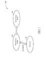
- FIG. 1 is a diagram illustrating link formation between two Wi-Fi Direct devices.
- a Wi-Fi Direct device 102 and a Wi-Fi Direct device 104 in a communication system 100 are performing link formation as a result of the Wi-Fi Direct device 102 inviting the Wi-Fi Direct device 104 or vice versa .
- one of the two Wi-Fi Direct devices 102 and 104 will be the Group Owner (GO), while the other will be the Group Client (GC).
- GO Group Owner
- GC Group Client
- a network domain address is assigned by the GO unilaterally, and the network domain addresses are often generated monotonously and prone to repeat.
- the present invention proposes exchanging network domain information between the two link partners, the network domain information indicating a network domain address of each link currently used by the two link partners (i.e. the GO and the GC), and using this information as the basis of further actions.
- the Wi-Fi Direct device 102 has an existing link with a Wi-Fi access point (AP) 106, and the network domain address assigned to the link is, for example, 192.168.0.X.
- the Wi-Fi Direct device 102 transmits network domain information to the Wi-Fi Direct device 104 to notify the Wi-Fi Direct device 104 that a network domain address 192.168.0.X is occupied and should not be reassigned till the link with the Wi-Fi AP 106 is disconnected, to prevent IP address conflict.
- the Wi-Fi Direct device 104 may also transmit network domain information to the Wi-Fi Direct device 102 to notify the Wi-Fi Direct device 102 that no network domain address is currently used or occupied by the Wi-Fi Direct device 104.
- the network domain information sent by the Wi-Fi Direct device 104 indicates a network domain address of each link currently used by the Wi-Fi Direct device 104; similarly, the network domain information sent by the Wi-Fi Direct device 102 may indicate a network domain address of each link currently used by the Wi-Fi Direct device 102.
- the network domain information may also include network domain addresses used by other devices connected to the Wi-Fi Direct devices 102 and/or 104. With the help of the exchanged network domain information, both the Wi-Fi Direct device 102 and the Wi-Fi Direct device 104 are capable of grasping the instant usage situation of the respective network domain addresses.
- the GO will determine whether to establish a new link between the Wi-Fi Direct device 102 and the Wi-Fi Direct device 104. For instance, if the network domain address is manually forced by a user and the GO judges that the manually forced address will cause IP address conflict, the GO may determine not to establish the new link between the Wi-Fi Direct device 102 and the Wi-Fi Direct device 104. This is for illustrative purposes only, and not a limitation of the present invention. If the GO determines that the situation is qualified and it is safe to establish the new link under provisions of the standard it complies with, the GO will determine a network domain address of the link according to the network domain information of GO and GC.
- the GO will select a specific network domain address different from 192.168.0.X as the network domain address for the new link between the Wi-Fi Direct device 102 and the Wi-Fi Direct device 104. IP address conflict can be easily avoided without requiring too much effort and time. If the GO has run out of IP addresses, i.e. no more different IP addresses can be provided for the new link, the GO may determine not to establish the new link. It should be noted that applying the proposed link formation method with reference to exchanged domain address information to Wi-Fi Direct devices is not meant to be a limitation of the present invention. By way of example, but not a limitation, the present invention may be applied to other wireless P2P standards, or even wired (cable) internet systems, and these applications employing the proposed link formation method all fall within the scope of the present invention.
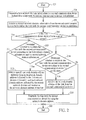
- FIG. 2 is a flowchart illustrating a linking method employed by a first communication device (e.g. one Wi-Fi Direct device) according to an embodiment of the present invention.
- a first communication device e.g. one Wi-Fi Direct device
- FIG. 2 is a flowchart illustrating a linking method employed by a first communication device (e.g. one Wi-Fi Direct device) according to an embodiment of the present invention.
- a first communication device e.g. one Wi-Fi Direct device
- the linking method may include the following steps.
- FIG. 3 is a flowchart illustrating a linking method for a communication system (e.g. the communication system 100 having two Wi-Fi Direct devices 102, 104) according to another embodiment of the present invention.
- a communication system e.g. the communication system 100 having two Wi-Fi Direct devices 102, 104
- the steps of the flowchart shown in FIG. 3 need not be in the exact order shown and need not be contiguous; that is, other steps can be intermediate. Some steps in FIG. 3 may be omitted according to various embodiments or requirements.
- the linking method may include the following steps.
- FIG. 1 An alternative design of the present invention is disclosed herein. Please refer to FIG. 1 again.
- the Wi-Fi Direct device 102 and the Wi-Fi Direct device 104 are performing link formation, and the Wi-Fi Direct device 102 has an existing link (192.168.0.X) with a Wi-Fi AP 106.
- the GO will determine a network domain address for the new link in a random manner.
- the GO will generate a network domain address randomly and unilaterally assign the randomly generated network domain address to the new link.
- the proposed domain address randomization method can dramatically decrease the probability of IP address conflict.
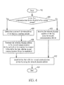
- FIG. 4 is a flowchart illustrating a linking method employed by a first communication device (e.g. one Wi-Fi Direct device) according to yet another embodiment of the present invention. Provided that substantially the same result is achieved, the steps of the flowchart shown in FIG. 4 need not be in the exact order shown and need not be contiguous; that is, other steps can be intermediate. Some steps in FIG. 4 may be omitted according to various embodiments or requirements.
- the linking method may include the following steps.
- FIG. 5 is a flowchart illustrating a linking method for a communication system (e.g. the communication system 100 having two Wi-Fi Direct devices 102, 104) according to yet another embodiment of the present invention.
- a communication system e.g. the communication system 100 having two Wi-Fi Direct devices 102, 104
- the steps of the flowchart shown in FIG. 5 need not be in the exact order shown and need not be contiguous; that is, other steps can be intermediate. Some steps in FIG. 5 may be omitted according to various embodiments or requirements.
- the linking method may include the following steps.
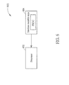
- the non-transitory machine readable medium 604 stores a program code PROG, wherein when the program code PROG is loaded and executed by the processor 602, the program code PROG enables the processor 602 to perform the disclosed linking method (i.e. steps 202-220 shown in FIG. 2 , or steps 402-414 shown in FIG. 4 ) of the present invention.
- the link establish control realized by the processor 602 executing the program code PROG further description will be omitted here for brevity.
Landscapes
- Engineering & Computer Science (AREA)
- Computer Networks & Wireless Communication (AREA)
- Signal Processing (AREA)
- Databases & Information Systems (AREA)
- Mobile Radio Communication Systems (AREA)
Abstract
Description
- The present invention relates to linking methods according to the pre-characterizing clauses of claims 1, 7, 13 and 15.
- Applications that enable devices to directly connect with each other without requiring an intermediate device are growing popular. For instance, Wi-Fi Direct (initially called Wi-Fi P2P) is a Wi-Fi standard that enables devices to connect easily with each other without requiring a wireless access point, enabling communication at typical Wi-Fi speeds for everything from file transfer to Internet connectivity. Wi-Fi Direct devices can connect one-to-one or one-to-many, which means that the Wi-Fi Direct devices may have more than one link at the same time.
- In the course of forming a link between two Wi-Fi Direct devices, the two devices will not realize the information associated with already existing link(s). As a result, an IP conflict may take place when a same IP domain as that of any existing link (s) is assigned when the new link is established. In this case, the condition that one of the Wi-Fi Direct devices has two links assigned with the same IP domain address at the same time will take place and cause a problem. Conventionally, the best option is to manually adjust these IP domain addresses so as to avoid conflicts. Such a solution is inefficient and troublesome, however, since the conflicts may remain unsolved for a long time and keep users waiting. The IP conflict issue in the field of P2P applications therefore needs to be addressed.
- This in mind, the present invention aims at providing linking methods to solve the above-mentioned problems.
- This is achieved by a linking method employed by a first communication device according to claims 1, 7, 13 and 15. The dependent claims pertain to corresponding further developments and improvements.
- As will be seen more clearly from the detailed description following below, the claimed linking method includes: transmitting a first network domain information to a second communication device before/after a link with the second communication device is established; and receiving a second network domain information from the second communication device before/after the link with the second communication device is established.
- Besides, a claimed linking method for a communication system is provided, where linking method includes: controlling the first communication device to transmit a first network domain information to the second communication device before/after a link between the first communication device and the second communication device is established; and controlling the second communication device to transmit a second network domain information to the first communication device before/after the link between the first communication device and the second communication device is established.
- Further, another claimed linking method employed by a first communication device is provided, where linking method includes: when the first communication device is decided to be a group owner before/after the link with a second communication device is established, determining a network domain address of the link in a random manner; and transmitting the network domain address to the second communication device before/after the link with the second communication device is established.
- Still further, another claimed linking method for a communication system is provided, where linking method includes: when a group owner is decided from the first communication device and the second communication device before/after the link between the first communication device and the second communication device is established, controlling the group owner to determine a network domain address of the link in a random manner; and controlling the group owner to transmit the network domain address to a group client before/after the link between the first communication device and the second communication device is established, wherein the group client is one of the first communication device and the second communication device apart from the group owner.
- In the following, the invention is further illustrated by way of example, taking reference to the accompanying drawings. Thereof
- FIG. 1
- is a diagram illustrating an example of performing link formation between two Wi-Fi Direct devices,
- FIG. 2
- is a flowchart illustrating a linking method employed by a first communication device according to an embodiment of the present invention,
- FIG. 3
- is a flowchart illustrating a linking method for a communication system according to another embodiment of the present invention,
- FIG. 4
- is a flowchart illustrating a linking method employed by a first communication device according to yet another embodiment of the present invention,
- FIG. 5
- is a flowchart illustrating a linking method for a communication system according to yet another embodiment of the present invention, and
- FIG. 6
- is a diagram illustrating a computer system for performing a linking method according to an exemplary embodiment of the present invention.
- One of the technical features of the present invention is to avoid IP domain address conflict when establishing a link between P2P devices such as two Wi-Fi Direct devices. Two main methods are disclosed, wherein one method comprises exchanging each device's network domain information concerning existing links while performing link formation or link negotiation; and the other method comprises determining a network domain address in a random manner while performing link formation or link negotiation. Further details are described in the following.
- For better understanding of the technical features of the present invention, please refer to
FIG. 1 , which is a diagram illustrating link formation between two Wi-Fi Direct devices. Suppose a Wi-FiDirect device 102 and a Wi-FiDirect device 104 in acommunication system 100 are performing link formation as a result of the Wi-FiDirect device 102 inviting the Wi-FiDirect device 104 or vice versa. In the course of the formation process according to the Wi-Fi Direct standard, one of the two Wi-FiDirect devices - As shown in
FIG. 1 , the Wi-FiDirect device 102 has an existing link with a Wi-Fi access point (AP) 106, and the network domain address assigned to the link is, for example, 192.168.0.X. According to the present invention, the Wi-FiDirect device 102 transmits network domain information to the Wi-FiDirect device 104 to notify the Wi-FiDirect device 104 that a network domain address 192.168.0.X is occupied and should not be reassigned till the link with the Wi-Fi AP 106 is disconnected, to prevent IP address conflict. The Wi-FiDirect device 104 may also transmit network domain information to the Wi-FiDirect device 102 to notify the Wi-FiDirect device 102 that no network domain address is currently used or occupied by the Wi-FiDirect device 104. The network domain information sent by the Wi-FiDirect device 104 indicates a network domain address of each link currently used by the Wi-FiDirect device 104; similarly, the network domain information sent by the Wi-FiDirect device 102 may indicate a network domain address of each link currently used by the Wi-FiDirect device 102. Moreover, the network domain information may also include network domain addresses used by other devices connected to the Wi-FiDirect devices 102 and/or 104. With the help of the exchanged network domain information, both the Wi-FiDirect device 102 and the Wi-FiDirect device 104 are capable of grasping the instant usage situation of the respective network domain addresses. - After the GO is determined, the GO will determine whether to establish a new link between the Wi-Fi
Direct device 102 and the Wi-FiDirect device 104. For instance, if the network domain address is manually forced by a user and the GO judges that the manually forced address will cause IP address conflict, the GO may determine not to establish the new link between the Wi-FiDirect device 102 and the Wi-FiDirect device 104. This is for illustrative purposes only, and not a limitation of the present invention. If the GO determines that the situation is qualified and it is safe to establish the new link under provisions of the standard it complies with, the GO will determine a network domain address of the link according to the network domain information of GO and GC. Specifically, the GO will select a specific network domain address different from 192.168.0.X as the network domain address for the new link between the Wi-FiDirect device 102 and the Wi-FiDirect device 104. IP address conflict can be easily avoided without requiring too much effort and time. If the GO has run out of IP addresses, i.e. no more different IP addresses can be provided for the new link, the GO may determine not to establish the new link. It should be noted that applying the proposed link formation method with reference to exchanged domain address information to Wi-Fi Direct devices is not meant to be a limitation of the present invention. By way of example, but not a limitation, the present invention may be applied to other wireless P2P standards, or even wired (cable) internet systems, and these applications employing the proposed link formation method all fall within the scope of the present invention. -
FIG. 2 is a flowchart illustrating a linking method employed by a first communication device (e.g. one Wi-Fi Direct device) according to an embodiment of the present invention. Provided that substantially the same result is achieved, the steps of the flowchart shown inFIG. 2 need not be in the exact order shown and need not be contiguous; that is, other steps can be intermediate. Some steps inFIG. 2 may be omitted according to various embodiments or requirements. - The linking method may include the following steps.
- Step 202:
- Start.
- Step 204:
- Transmit a first network domain information to a second communication device (e.g. another Wi-Fi Direct device) before/after a link with the second communication device is established.
- Step 206:
- Receive a second network domain information from the second communication device before/after the link with the second communication device is established.
- Step 208:
- Determine whether the first communication device is a group owner? If yes, go to step 210; otherwise, go to step 214.
- Step 210:
- Determine whether to establish the link with the second communication device according to the first network domain information and the second network domain information. If yes, go to step 212; otherwise, go to step 220.
- Step 212:
- Select a specific network domain address different from each network domain address indicated by the first network domain information and each network domain address indicated by the second network domain information as the network domain address of the link.
- Step 214:
- Determine whether to establish the link with the second communication device according to the second communication device's notification. If yes, go to step 216; otherwise, go to step 220.
- Step 216:
- Receive the network domain address of the link from the second communication device.
- Step 218:
- Establish the link with the second communication device by using the network domain address.
- Step 220:
- End.
- Please refer to
FIG. 3 , which is a flowchart illustrating a linking method for a communication system (e.g. thecommunication system 100 having two Wi-Fi Direct devices 102, 104) according to another embodiment of the present invention. Provided that substantially the same result is achieved, the steps of the flowchart shown inFIG. 3 need not be in the exact order shown and need not be contiguous; that is, other steps can be intermediate. Some steps inFIG. 3 may be omitted according to various embodiments or requirements. The linking method may include the following steps. - Step 302:
- Start.
- Step 304:
- The first communication device (e.g. one Wi-Fi Direct device) transmits a first network domain information to the second communication device (e.g., another Wi-Fi Direct device) before/after a link between the first communication device and the second communication device is established.
- Step 306:
- The second communication device transmits a second network domain information to the first communication device before/after the link between the first communication device and the second communication device is established.
- Step 308:
- Determine whether to establish the link between the first communication device and the second communication device according to the first network domain information and the second network domain information. If yes, go to step 310; otherwise, go to step 314.
- Step 310:
- Select a specific network domain address different from each network domain address indicated by the first network domain information and each network domain address indicated by the second network domain information as the network domain address of the link.
- Step 312:
- Establish the link with the second communication device by using the selected network domain address.
- Step 314:
- End.
- As a person skilled in the art can readily understand the details of the steps shown in
FIG. 2 andFIG. 3 after reading the above paragraphs directed to the linking method shown inFIG. 1 , further description is omitted here for brevity. - An alternative design of the present invention is disclosed herein. Please refer to
FIG. 1 again. Suppose the Wi-Fi Direct device 102 and the Wi-Fi Direct device 104 are performing link formation, and the Wi-Fi Direct device 102 has an existing link (192.168.0.X) with a Wi-Fi AP 106. In this embodiment, after the GO is determined, the GO will determine a network domain address for the new link in a random manner. The GO will generate a network domain address randomly and unilaterally assign the randomly generated network domain address to the new link. Compared with the network domain addresses assigned in the conventional design which are often generated in a serial manner and prone to repeat, the proposed domain address randomization method can dramatically decrease the probability of IP address conflict. -
FIG. 4 is a flowchart illustrating a linking method employed by a first communication device (e.g. one Wi-Fi Direct device) according to yet another embodiment of the present invention. Provided that substantially the same result is achieved, the steps of the flowchart shown inFIG. 4 need not be in the exact order shown and need not be contiguous; that is, other steps can be intermediate. Some steps inFIG. 4 may be omitted according to various embodiments or requirements. The linking method may include the following steps. - Step 402:
- Start.
- Step 404:
- Determine whether the first communication device is a group owner? If yes, go to step 406; otherwise, go to step 410.
- Step 406:
- Determine a network domain address of the link in a random manner.
- Step 408:
- Transmit the network domain address to a second communication device (e.g. another Wi-Fi Direct device) actively or in response to a request before/after the link with the second communication device is established.
- Step 410:
- Receive the network domain address of the link from the second communication device.
- Step 412:
- Establish the link with the second communication device by using the network domain address.
- Step 414:
- End.
- Please refer to
FIG. 5 , which is a flowchart illustrating a linking method for a communication system (e.g. thecommunication system 100 having two Wi-Fi Direct devices 102, 104) according to yet another embodiment of the present invention. Provided that substantially the same result is achieved, the steps of the flowchart shown inFIG. 5 need not be in the exact order shown and need not be contiguous; that is, other steps can be intermediate. Some steps inFIG. 5 may be omitted according to various embodiments or requirements. The linking method may include the following steps. - Step 502:
- Start.
- Step 504:
- The group owner determines a network domain address of the link in a random manner before/after the link between the first communication device and the second communication device (e.g. Wi-
Fi Direct devices 102 and 104) is established. - Step 506:
- The group owner transmits the network domain address to a group client actively or in response to a request of the group client before/after before/after the link between the first communication device and the second communication device is established, wherein the group client is one of the first communication device and the second communication device apart from the group owner.
- Step 508:
- Establish the link between the first communication device and the second communication device by using the network domain address.
- Step 510:
- End.
- As a person skilled in the art can readily understand the details of each step shown in
FIG. 4 andFIG. 5 after reading the above paragraphs associated with the linking method which randomly generates the network domain address, further description is omitted here for brevity. - Please refer to
FIG. 6 , which is a diagram illustrating a computer system for performing a linking method according to an exemplary embodiment of the present invention. Thecomputer system 600 may be implemented in either or both of the Wi-Fi Direct devices computer system 600 includes aprocessor 602 and a non-transitory machinereadable medium 604. For instance, thecomputer system 600 could be a personal computer, and the non-transitory machinereadable medium 604 could be any storage device capable of storing data in a personal computer, e.g. volatile memory, non-volatile memory, hard disk, CD-ROM, etc. In this embodiment, the non-transitory machine readable medium 604 stores a program code PROG, wherein when the program code PROG is loaded and executed by theprocessor 602, the program code PROG enables theprocessor 602 to perform the disclosed linking method (i.e. steps 202-220 shown inFIG. 2 , or steps 402-414 shown inFIG. 4 ) of the present invention. As those skilled in the art should readily understand the link establish control realized by theprocessor 602 executing the program code PROG, further description will be omitted here for brevity. - All combinations and sub-combinations of above-described features also belong to the invention.
Claims (15)
- A linking method employed by a first communication device (102, 104), characterized by:transmitting a first network domain information to a second communication device (102, 104) before/after a link with the second communication device (102, 104) is established; andreceiving a second network domain information from the second communication device (102, 104) before/after the link with the second communication device (102, 104) is established.
- The linking method of claim 1, characterized in that the first network domain information indicates a network domain address of each link currently used by the first communication device (102, 104).
- The linking method of claim 1, characterized in that the second network domain information indicates a network domain address of each link currently used by the second communication device (102, 104).
- The linking method of claim 1, characterized by:when the first communication device (102, 104) is decided to be a group owner, determining a network domain address of the link according to the first network domain information and the second network domain information.
- The linking method of claim 4, characterized in that the first network domain information indicates a network domain address of each link currently used by the first communication device (102, 104) ; the second network domain information indicates a network domain address of each link currently used by the second communication device (102, 104) ; and the step of determining the network domain address of the link comprises:selecting a specific network domain address different from each network domain address indicated by the first network domain information and each network domain address indicated by the second network domain information as the network domain address of the link.
- The linking method of claim 1, characterized by:when the first communication device (102, 104) is decided to be a group owner, determining whether to establish the link with the second communication device (102, 104) according to the first network domain information and the second network domain information.
- A linking method for a communication system, characterized in that the communication system includes a first communication device (102, 104) and a second communication device (102, 104); the link method comprising:transmitting by the first communication device (102, 104) a first network domain information to the second communication device (102, 104) before/after a link between the first communication device (102, 104) and the second communication device (102, 104) is established; andtransmitting by the second communication device (102, 104) a second network domain information to the first communication device (102, 104) before/after the link between the first communication device (102, 104) and the second communication device (102, 104) is established.
- The linking method of claim 7, characterized in that the first network domain information indicates a network domain address of each link currently used by the first communication device (102, 104).
- The linking method of claim 7, characterized in that the second network domain information indicates a network domain address of each link currently used by the second communication device (102, 104).
- The linking method of claim 7, characterized by:determining a network domain of the link according to the first network domain information and the second network domain information.
- The linking method of claim 10, characterized in that the first network domain information indicates a network domain address of each link currently used by the first communication device (102, 104); the second network domain information indicates a network domain address of each link currently used by the second communication device (102, 104) ; and the step of determining the network domain address of the link comprises:selecting a specific network domain address different from each network domain address indicated by the first network domain information and each network domain address indicated by the second network domain information as the network domain address of the link.
- The linking method of claim 7, characterized by:determining whether to establish the link between the first communication device (102, 104) and the second communication device (102, 104) according to the first network domain information and the second network domain information.
- A linking method employed by a first communication device (102, 104), characterized by:when the first communication device (102, 104) is decided to be a group owner before/after the link with a second communication device (102, 104) is established, determining a network domain address of the link in a random manner; andtransmitting the network domain address to the second communication device (102, 104) before/after the link with the second communication device (102, 104) is established.
- The linking method of claim 13, characterized by,
transmitting a first network domain information to the second communication device (102, 104); and
receiving a second network domain information from the second communication device (102, 104),
if the network domain address conflicts with the first network domain information and/or the second network domain information, selecting a new network domain address to the second communication device (102, 104). - A linking method for a communication system, characterized in that the communication system includes a first communication device (102, 104) and a second communication device (102, 104); the link method comprising:when a group owner is decided from the first communication device (102, 104) and the second communication device (102, 104) before/after a link between the first communication device (102, 104) and the second communication device (102, 104) is established, controlling the group owner to determine a network domain address of the link in a random manner; andtransmitting the network domain address by the group owner to a group client before/after the link between the first communication device (102, 104) and the second communication device (102, 104) is established, wherein the group client is one of the first communication device (102, 104) and the second communication device (102, 104) except the group owner.
Applications Claiming Priority (1)
| Application Number | Priority Date | Filing Date | Title |
|---|---|---|---|
| US14/251,665 US9554407B2 (en) | 2013-05-20 | 2014-04-14 | Linking method between communication devices and related machine readable medium |
Publications (2)
| Publication Number | Publication Date |
|---|---|
| EP2934029A1 true EP2934029A1 (en) | 2015-10-21 |
| EP2934029B1 EP2934029B1 (en) | 2019-05-22 |
Family
ID=52779516
Family Applications (1)
| Application Number | Title | Priority Date | Filing Date |
|---|---|---|---|
| EP15160387.5A Active EP2934029B1 (en) | 2014-04-14 | 2015-03-23 | Linking method between communication devices and related machine readable medium |
Country Status (1)
| Country | Link |
|---|---|
| EP (1) | EP2934029B1 (en) |
Cited By (1)
| Publication number | Priority date | Publication date | Assignee | Title |
|---|---|---|---|---|
| CN115002939A (en) * | 2022-07-18 | 2022-09-02 | 荣耀终端有限公司 | Method and device for joining WiFi group |
Citations (2)
| Publication number | Priority date | Publication date | Assignee | Title |
|---|---|---|---|---|
| US20120290731A1 (en) * | 2010-12-29 | 2012-11-15 | Nokia Corporation | Network setup via short-range communication |
| WO2013145045A1 (en) * | 2012-03-30 | 2013-10-03 | Necカシオモバイルコミュニケーションズ株式会社 | Wireless device, address determination method, communication system, and wireless terminal |
-
2015
- 2015-03-23 EP EP15160387.5A patent/EP2934029B1/en active Active
Patent Citations (3)
| Publication number | Priority date | Publication date | Assignee | Title |
|---|---|---|---|---|
| US20120290731A1 (en) * | 2010-12-29 | 2012-11-15 | Nokia Corporation | Network setup via short-range communication |
| WO2013145045A1 (en) * | 2012-03-30 | 2013-10-03 | Necカシオモバイルコミュニケーションズ株式会社 | Wireless device, address determination method, communication system, and wireless terminal |
| EP2833658A1 (en) * | 2012-03-30 | 2015-02-04 | NEC CASIO Mobile Communications, Ltd. | Wireless device, address determination method, communication system, and wireless terminal |
Cited By (2)
| Publication number | Priority date | Publication date | Assignee | Title |
|---|---|---|---|---|
| CN115002939A (en) * | 2022-07-18 | 2022-09-02 | 荣耀终端有限公司 | Method and device for joining WiFi group |
| CN115002939B (en) * | 2022-07-18 | 2022-10-04 | 荣耀终端有限公司 | Method and device for joining WiFi group |
Also Published As
| Publication number | Publication date |
|---|---|
| EP2934029B1 (en) | 2019-05-22 |
Similar Documents
| Publication | Publication Date | Title |
|---|---|---|
| JP6199379B2 (en) | System and method for persistent wireless docking | |
| JP5540115B2 (en) | Electronic device and method of operating electronic device | |
| US9781756B2 (en) | Device pairing | |
| JP2015525505A5 (en) | ||
| US20180103499A1 (en) | Control method for bluetooth communication and bluetooth low energy communication | |
| TW201132083A (en) | Group owner selection with crossing requests | |
| JP6311697B2 (en) | Data sharing system | |
| JP2016042230A (en) | Content transfer program, device, and method | |
| EP2934029A1 (en) | Linking method between communication devices and related machine readable medium | |
| CN105451367A (en) | Wireless network connection method, device and system | |
| US10972356B2 (en) | Method for selecting negotiation counterpart, method for responding to discovery message, and related apparatus | |
| EP2950606B1 (en) | Communication device, method for controlling communication device, and program | |
| US20160100021A1 (en) | Information processing device, destination information updating method, and record medium | |
| US9554407B2 (en) | Linking method between communication devices and related machine readable medium | |
| WO2014129153A1 (en) | Communication apparatus, control method for the communication apparatus, and program | |
| JP2015111330A (en) | Terminal device, communication system, and communication program | |
| JP6365531B2 (en) | Access point decision method | |
| WO2016095470A1 (en) | Method and gslb for data push | |
| US11196831B2 (en) | Communication apparatus, communication method, and storage medium | |
| JP6662124B2 (en) | Communication device, history information management method, and history information management program | |
| JP2018078395A (en) | Apparatus communication method and apparatus | |
| US20160165427A1 (en) | Network communication method | |
| JP6272570B2 (en) | Object and communication program | |
| CN106332026B (en) | Method for realizing multimedia short message in cluster system, core network and resource server | |
| US9602687B2 (en) | Communication apparatus, method for controlling communication with an external apparatus using generated session and changed session, and program therefor |
Legal Events
| Date | Code | Title | Description |
|---|---|---|---|
| PUAI | Public reference made under article 153(3) epc to a published international application that has entered the european phase |
Free format text: ORIGINAL CODE: 0009012 |
|
| AK | Designated contracting states |
Kind code of ref document: A1 Designated state(s): AL AT BE BG CH CY CZ DE DK EE ES FI FR GB GR HR HU IE IS IT LI LT LU LV MC MK MT NL NO PL PT RO RS SE SI SK SM TR |
|
| AX | Request for extension of the european patent |
Extension state: BA ME |
|
| 17P | Request for examination filed |
Effective date: 20151211 |
|
| RBV | Designated contracting states (corrected) |
Designated state(s): AL AT BE BG CH CY CZ DE DK EE ES FI FR GB GR HR HU IE IS IT LI LT LU LV MC MK MT NL NO PL PT RO RS SE SI SK SM TR |
|
| STAA | Information on the status of an ep patent application or granted ep patent |
Free format text: STATUS: EXAMINATION IS IN PROGRESS |
|
| 17Q | First examination report despatched |
Effective date: 20180219 |
|
| GRAP | Despatch of communication of intention to grant a patent |
Free format text: ORIGINAL CODE: EPIDOSNIGR1 |
|
| STAA | Information on the status of an ep patent application or granted ep patent |
Free format text: STATUS: GRANT OF PATENT IS INTENDED |
|
| RIC1 | Information provided on ipc code assigned before grant |
Ipc: H04W 8/00 20090101AFI20190115BHEP Ipc: H04L 29/12 20060101ALN20190115BHEP Ipc: H04W 76/14 20180101ALI20190115BHEP |
|
| INTG | Intention to grant announced |
Effective date: 20190214 |
|
| GRAJ | Information related to disapproval of communication of intention to grant by the applicant or resumption of examination proceedings by the epo deleted |
Free format text: ORIGINAL CODE: EPIDOSDIGR1 |
|
| STAA | Information on the status of an ep patent application or granted ep patent |
Free format text: STATUS: EXAMINATION IS IN PROGRESS |
|
| GRAR | Information related to intention to grant a patent recorded |
Free format text: ORIGINAL CODE: EPIDOSNIGR71 |
|
| GRAS | Grant fee paid |
Free format text: ORIGINAL CODE: EPIDOSNIGR3 |
|
| STAA | Information on the status of an ep patent application or granted ep patent |
Free format text: STATUS: GRANT OF PATENT IS INTENDED |
|
| GRAA | (expected) grant |
Free format text: ORIGINAL CODE: 0009210 |
|
| STAA | Information on the status of an ep patent application or granted ep patent |
Free format text: STATUS: THE PATENT HAS BEEN GRANTED |
|
| INTC | Intention to grant announced (deleted) | ||
| RIC1 | Information provided on ipc code assigned before grant |
Ipc: H04L 29/12 20060101ALN20190403BHEP Ipc: H04W 76/14 20180101ALI20190403BHEP Ipc: H04W 8/00 20090101AFI20190403BHEP |
|
| AK | Designated contracting states |
Kind code of ref document: B1 Designated state(s): AL AT BE BG CH CY CZ DE DK EE ES FI FR GB GR HR HU IE IS IT LI LT LU LV MC MK MT NL NO PL PT RO RS SE SI SK SM TR |
|
| INTG | Intention to grant announced |
Effective date: 20190416 |
|
| REG | Reference to a national code |
Ref country code: GB Ref legal event code: FG4D |
|
| REG | Reference to a national code |
Ref country code: CH Ref legal event code: EP |
|
| REG | Reference to a national code |
Ref country code: IE Ref legal event code: FG4D |
|
| REG | Reference to a national code |
Ref country code: DE Ref legal event code: R096 Ref document number: 602015030602 Country of ref document: DE |
|
| REG | Reference to a national code |
Ref country code: AT Ref legal event code: REF Ref document number: 1137571 Country of ref document: AT Kind code of ref document: T Effective date: 20190615 |
|
| REG | Reference to a national code |
Ref country code: NL Ref legal event code: MP Effective date: 20190522 |
|
| REG | Reference to a national code |
Ref country code: LT Ref legal event code: MG4D |
|
| PG25 | Lapsed in a contracting state [announced via postgrant information from national office to epo] |
Ref country code: NL Free format text: LAPSE BECAUSE OF FAILURE TO SUBMIT A TRANSLATION OF THE DESCRIPTION OR TO PAY THE FEE WITHIN THE PRESCRIBED TIME-LIMIT Effective date: 20190522 Ref country code: ES Free format text: LAPSE BECAUSE OF FAILURE TO SUBMIT A TRANSLATION OF THE DESCRIPTION OR TO PAY THE FEE WITHIN THE PRESCRIBED TIME-LIMIT Effective date: 20190522 Ref country code: LT Free format text: LAPSE BECAUSE OF FAILURE TO SUBMIT A TRANSLATION OF THE DESCRIPTION OR TO PAY THE FEE WITHIN THE PRESCRIBED TIME-LIMIT Effective date: 20190522 Ref country code: HR Free format text: LAPSE BECAUSE OF FAILURE TO SUBMIT A TRANSLATION OF THE DESCRIPTION OR TO PAY THE FEE WITHIN THE PRESCRIBED TIME-LIMIT Effective date: 20190522 Ref country code: PT Free format text: LAPSE BECAUSE OF FAILURE TO SUBMIT A TRANSLATION OF THE DESCRIPTION OR TO PAY THE FEE WITHIN THE PRESCRIBED TIME-LIMIT Effective date: 20190922 Ref country code: NO Free format text: LAPSE BECAUSE OF FAILURE TO SUBMIT A TRANSLATION OF THE DESCRIPTION OR TO PAY THE FEE WITHIN THE PRESCRIBED TIME-LIMIT Effective date: 20190822 Ref country code: SE Free format text: LAPSE BECAUSE OF FAILURE TO SUBMIT A TRANSLATION OF THE DESCRIPTION OR TO PAY THE FEE WITHIN THE PRESCRIBED TIME-LIMIT Effective date: 20190522 Ref country code: AL Free format text: LAPSE BECAUSE OF FAILURE TO SUBMIT A TRANSLATION OF THE DESCRIPTION OR TO PAY THE FEE WITHIN THE PRESCRIBED TIME-LIMIT Effective date: 20190522 Ref country code: FI Free format text: LAPSE BECAUSE OF FAILURE TO SUBMIT A TRANSLATION OF THE DESCRIPTION OR TO PAY THE FEE WITHIN THE PRESCRIBED TIME-LIMIT Effective date: 20190522 |
|
| PG25 | Lapsed in a contracting state [announced via postgrant information from national office to epo] |
Ref country code: LV Free format text: LAPSE BECAUSE OF FAILURE TO SUBMIT A TRANSLATION OF THE DESCRIPTION OR TO PAY THE FEE WITHIN THE PRESCRIBED TIME-LIMIT Effective date: 20190522 Ref country code: RS Free format text: LAPSE BECAUSE OF FAILURE TO SUBMIT A TRANSLATION OF THE DESCRIPTION OR TO PAY THE FEE WITHIN THE PRESCRIBED TIME-LIMIT Effective date: 20190522 Ref country code: GR Free format text: LAPSE BECAUSE OF FAILURE TO SUBMIT A TRANSLATION OF THE DESCRIPTION OR TO PAY THE FEE WITHIN THE PRESCRIBED TIME-LIMIT Effective date: 20190823 Ref country code: BG Free format text: LAPSE BECAUSE OF FAILURE TO SUBMIT A TRANSLATION OF THE DESCRIPTION OR TO PAY THE FEE WITHIN THE PRESCRIBED TIME-LIMIT Effective date: 20190822 |
|
| REG | Reference to a national code |
Ref country code: AT Ref legal event code: MK05 Ref document number: 1137571 Country of ref document: AT Kind code of ref document: T Effective date: 20190522 |
|
| PG25 | Lapsed in a contracting state [announced via postgrant information from national office to epo] |
Ref country code: CZ Free format text: LAPSE BECAUSE OF FAILURE TO SUBMIT A TRANSLATION OF THE DESCRIPTION OR TO PAY THE FEE WITHIN THE PRESCRIBED TIME-LIMIT Effective date: 20190522 Ref country code: SK Free format text: LAPSE BECAUSE OF FAILURE TO SUBMIT A TRANSLATION OF THE DESCRIPTION OR TO PAY THE FEE WITHIN THE PRESCRIBED TIME-LIMIT Effective date: 20190522 Ref country code: EE Free format text: LAPSE BECAUSE OF FAILURE TO SUBMIT A TRANSLATION OF THE DESCRIPTION OR TO PAY THE FEE WITHIN THE PRESCRIBED TIME-LIMIT Effective date: 20190522 Ref country code: RO Free format text: LAPSE BECAUSE OF FAILURE TO SUBMIT A TRANSLATION OF THE DESCRIPTION OR TO PAY THE FEE WITHIN THE PRESCRIBED TIME-LIMIT Effective date: 20190522 Ref country code: AT Free format text: LAPSE BECAUSE OF FAILURE TO SUBMIT A TRANSLATION OF THE DESCRIPTION OR TO PAY THE FEE WITHIN THE PRESCRIBED TIME-LIMIT Effective date: 20190522 Ref country code: DK Free format text: LAPSE BECAUSE OF FAILURE TO SUBMIT A TRANSLATION OF THE DESCRIPTION OR TO PAY THE FEE WITHIN THE PRESCRIBED TIME-LIMIT Effective date: 20190522 |
|
| REG | Reference to a national code |
Ref country code: DE Ref legal event code: R097 Ref document number: 602015030602 Country of ref document: DE |
|
| PG25 | Lapsed in a contracting state [announced via postgrant information from national office to epo] |
Ref country code: SM Free format text: LAPSE BECAUSE OF FAILURE TO SUBMIT A TRANSLATION OF THE DESCRIPTION OR TO PAY THE FEE WITHIN THE PRESCRIBED TIME-LIMIT Effective date: 20190522 Ref country code: IT Free format text: LAPSE BECAUSE OF FAILURE TO SUBMIT A TRANSLATION OF THE DESCRIPTION OR TO PAY THE FEE WITHIN THE PRESCRIBED TIME-LIMIT Effective date: 20190522 |
|
| PLBE | No opposition filed within time limit |
Free format text: ORIGINAL CODE: 0009261 |
|
| STAA | Information on the status of an ep patent application or granted ep patent |
Free format text: STATUS: NO OPPOSITION FILED WITHIN TIME LIMIT |
|
| PG25 | Lapsed in a contracting state [announced via postgrant information from national office to epo] |
Ref country code: TR Free format text: LAPSE BECAUSE OF FAILURE TO SUBMIT A TRANSLATION OF THE DESCRIPTION OR TO PAY THE FEE WITHIN THE PRESCRIBED TIME-LIMIT Effective date: 20190522 |
|
| 26N | No opposition filed |
Effective date: 20200225 |
|
| PG25 | Lapsed in a contracting state [announced via postgrant information from national office to epo] |
Ref country code: PL Free format text: LAPSE BECAUSE OF FAILURE TO SUBMIT A TRANSLATION OF THE DESCRIPTION OR TO PAY THE FEE WITHIN THE PRESCRIBED TIME-LIMIT Effective date: 20190522 |
|
| PG25 | Lapsed in a contracting state [announced via postgrant information from national office to epo] |
Ref country code: SI Free format text: LAPSE BECAUSE OF FAILURE TO SUBMIT A TRANSLATION OF THE DESCRIPTION OR TO PAY THE FEE WITHIN THE PRESCRIBED TIME-LIMIT Effective date: 20190522 |
|
| PG25 | Lapsed in a contracting state [announced via postgrant information from national office to epo] |
Ref country code: MC Free format text: LAPSE BECAUSE OF FAILURE TO SUBMIT A TRANSLATION OF THE DESCRIPTION OR TO PAY THE FEE WITHIN THE PRESCRIBED TIME-LIMIT Effective date: 20190522 |
|
| REG | Reference to a national code |
Ref country code: CH Ref legal event code: PL |
|
| REG | Reference to a national code |
Ref country code: BE Ref legal event code: MM Effective date: 20200331 |
|
| PG25 | Lapsed in a contracting state [announced via postgrant information from national office to epo] |
Ref country code: LU Free format text: LAPSE BECAUSE OF NON-PAYMENT OF DUE FEES Effective date: 20200323 |
|
| PG25 | Lapsed in a contracting state [announced via postgrant information from national office to epo] |
Ref country code: IE Free format text: LAPSE BECAUSE OF NON-PAYMENT OF DUE FEES Effective date: 20200323 Ref country code: LI Free format text: LAPSE BECAUSE OF NON-PAYMENT OF DUE FEES Effective date: 20200331 Ref country code: CH Free format text: LAPSE BECAUSE OF NON-PAYMENT OF DUE FEES Effective date: 20200331 |
|
| PG25 | Lapsed in a contracting state [announced via postgrant information from national office to epo] |
Ref country code: BE Free format text: LAPSE BECAUSE OF NON-PAYMENT OF DUE FEES Effective date: 20200331 |
|
| PG25 | Lapsed in a contracting state [announced via postgrant information from national office to epo] |
Ref country code: MT Free format text: LAPSE BECAUSE OF FAILURE TO SUBMIT A TRANSLATION OF THE DESCRIPTION OR TO PAY THE FEE WITHIN THE PRESCRIBED TIME-LIMIT Effective date: 20190522 Ref country code: CY Free format text: LAPSE BECAUSE OF FAILURE TO SUBMIT A TRANSLATION OF THE DESCRIPTION OR TO PAY THE FEE WITHIN THE PRESCRIBED TIME-LIMIT Effective date: 20190522 |
|
| PG25 | Lapsed in a contracting state [announced via postgrant information from national office to epo] |
Ref country code: MK Free format text: LAPSE BECAUSE OF FAILURE TO SUBMIT A TRANSLATION OF THE DESCRIPTION OR TO PAY THE FEE WITHIN THE PRESCRIBED TIME-LIMIT Effective date: 20190522 Ref country code: IS Free format text: LAPSE BECAUSE OF FAILURE TO SUBMIT A TRANSLATION OF THE DESCRIPTION OR TO PAY THE FEE WITHIN THE PRESCRIBED TIME-LIMIT Effective date: 20190922 |
|
| PGFP | Annual fee paid to national office [announced via postgrant information from national office to epo] |
Ref country code: FR Payment date: 20230327 Year of fee payment: 9 |
|
| P01 | Opt-out of the competence of the unified patent court (upc) registered |
Effective date: 20230607 |
|
| PGFP | Annual fee paid to national office [announced via postgrant information from national office to epo] |
Ref country code: DE Payment date: 20240327 Year of fee payment: 10 Ref country code: GB Payment date: 20240327 Year of fee payment: 10 |