EP2932774B1 - Systems and methods for user equipment mobility prediction - Google Patents
Systems and methods for user equipment mobility prediction Download PDFInfo
- Publication number
- EP2932774B1 EP2932774B1 EP13863633.7A EP13863633A EP2932774B1 EP 2932774 B1 EP2932774 B1 EP 2932774B1 EP 13863633 A EP13863633 A EP 13863633A EP 2932774 B1 EP2932774 B1 EP 2932774B1
- Authority
- EP
- European Patent Office
- Prior art keywords
- location
- mobility
- mobile device
- mobility prediction
- predictor
- Prior art date
- Legal status (The legal status is an assumption and is not a legal conclusion. Google has not performed a legal analysis and makes no representation as to the accuracy of the status listed.)
- Active
Links
- 238000000034 method Methods 0.000 title claims description 45
- 238000012549 training Methods 0.000 claims description 21
- 230000008859 change Effects 0.000 claims description 5
- 238000013461 design Methods 0.000 claims description 2
- 238000001514 detection method Methods 0.000 claims description 2
- 238000005259 measurement Methods 0.000 claims description 2
- 238000012545 processing Methods 0.000 description 14
- 230000015654 memory Effects 0.000 description 8
- 230000007246 mechanism Effects 0.000 description 4
- 238000004891 communication Methods 0.000 description 3
- 238000012937 correction Methods 0.000 description 3
- 238000010586 diagram Methods 0.000 description 3
- 238000007726 management method Methods 0.000 description 3
- 238000011056 performance test Methods 0.000 description 3
- 230000009467 reduction Effects 0.000 description 3
- 238000004088 simulation Methods 0.000 description 3
- 230000001186 cumulative effect Effects 0.000 description 2
- 238000005315 distribution function Methods 0.000 description 2
- 238000013468 resource allocation Methods 0.000 description 2
- 230000006978 adaptation Effects 0.000 description 1
- 238000013459 approach Methods 0.000 description 1
- 230000005540 biological transmission Effects 0.000 description 1
- 238000010276 construction Methods 0.000 description 1
- 238000013500 data storage Methods 0.000 description 1
- 230000006870 function Effects 0.000 description 1
- 230000010354 integration Effects 0.000 description 1
- 230000003287 optical effect Effects 0.000 description 1
- 230000000737 periodic effect Effects 0.000 description 1
- 230000002093 peripheral effect Effects 0.000 description 1
- 230000008569 process Effects 0.000 description 1
- 239000007787 solid Substances 0.000 description 1
- 230000003068 static effect Effects 0.000 description 1
- 230000001360 synchronised effect Effects 0.000 description 1
- 230000009466 transformation Effects 0.000 description 1
- 230000001960 triggered effect Effects 0.000 description 1
Images


Classifications
-
- H—ELECTRICITY
- H04—ELECTRIC COMMUNICATION TECHNIQUE
- H04W—WIRELESS COMMUNICATION NETWORKS
- H04W64/00—Locating users or terminals or network equipment for network management purposes, e.g. mobility management
- H04W64/006—Locating users or terminals or network equipment for network management purposes, e.g. mobility management with additional information processing, e.g. for direction or speed determination
-
- G—PHYSICS
- G01—MEASURING; TESTING
- G01S—RADIO DIRECTION-FINDING; RADIO NAVIGATION; DETERMINING DISTANCE OR VELOCITY BY USE OF RADIO WAVES; LOCATING OR PRESENCE-DETECTING BY USE OF THE REFLECTION OR RERADIATION OF RADIO WAVES; ANALOGOUS ARRANGEMENTS USING OTHER WAVES
- G01S5/00—Position-fixing by co-ordinating two or more direction or position line determinations; Position-fixing by co-ordinating two or more distance determinations
- G01S5/0009—Transmission of position information to remote stations
- G01S5/0018—Transmission from mobile station to base station
-
- G—PHYSICS
- G01—MEASURING; TESTING
- G01S—RADIO DIRECTION-FINDING; RADIO NAVIGATION; DETERMINING DISTANCE OR VELOCITY BY USE OF RADIO WAVES; LOCATING OR PRESENCE-DETECTING BY USE OF THE REFLECTION OR RERADIATION OF RADIO WAVES; ANALOGOUS ARRANGEMENTS USING OTHER WAVES
- G01S5/00—Position-fixing by co-ordinating two or more direction or position line determinations; Position-fixing by co-ordinating two or more distance determinations
- G01S5/02—Position-fixing by co-ordinating two or more direction or position line determinations; Position-fixing by co-ordinating two or more distance determinations using radio waves
- G01S5/0205—Details
- G01S5/021—Calibration, monitoring or correction
Definitions
- the present invention relates to a system and method for wireless communications, and, in particular embodiments, to a system and method for user equipment mobility prediction.
- the location of a mobile wireless device in a wireless network may be important for a variety of applications, such as providing maps and directions to users. The location may also be important in order to provide directions for emergency personal should the user of the mobile wireless device need assistance. Other applications, such as traffic reporting, weather reports, identity of nearby restaurants, stores, and cinemas may also depend on the location of the mobile wireless device. Different applications may have different requirements for the level of precision with which the mobile wireless device's location must be determined. A number of mechanisms have been developed for determining the actual location of a wireless device. However, these mechanisms often require the wireless device to report its location to the network frequently, thereby using up network resources.
- WO 2009/019672 A1 US 2007/0049289 A1 , GB 2277844 A and WO 00/72619 A1 describe approaches where location data is sent based on a condition.
- UE mobility is one of the challenging issues for effective resource management.
- QoS quality of service
- a driver who requests a service with tight quality of service (QoS) constraints might be going into a long tunnel very soon, where there will be no signal coverage.
- QoS quality of service
- the system should generally not admit this service as the system will not be able to provide enough capacity to satisfy the QoS requirements of this service.
- mobility management is also used for other resource allocation domains such as flow control, routing, packet scheduling, etc.
- An embodiment provides a mobility management solution for service admission. The embodiment methodology can be applied to other resource allocation areas such as routing, flow control, etc.
- the UE and the system exchange messages with each other to negotiate a mobility prediction protocol.
- the mobility prediction protocol specifies a mobility predictor to be used by both the UE and the system in parallel with each other.
- the mobility prediction protocol also specifies the parameters that the UE will provide to the system (e.g., a location and time stamps for a specified number of previous locations for the UE) for training the mobility predictor.
- the locations and timestamps are used by the UE and the system to train the mobility predictor so that both the UE and the system predict the same location for a given time.
- the mobility prediction protocol also specifies the condition(s) upon which the UE will report its actual location to the system.
- the UE After the training period, the UE only reports its actual location to the system if the condition(s) for reporting are satisfied. Otherwise, the UE will refrain from transmitting actual location information and the system assumes that its predicted location for the UE is the actual location for the UE.
- the mobile location may be defined as an absolute location (e.g., geographic location - longitude and latitude), a location relative to the network infrastructure (e.g., received radio signal strength from network radio nodes, pathloss, average signal to noise ratio (SNR), etc.), or location relative to one or more nearby landscape references (e.g., buildings, constructions, bridges, roads, parks, recreation areas, etc.).
- the mobile report content may include any type of location as defined above, current and/or historical locations of the mobile device, information on a route plan (if available, such as a GPS plan), and predictor-specific data associated with location information.
- the location reported to the system may be as a change in reference to a previous report (e.g., 10 meters north of last location).
- An embodiment provides a simple system to enable online mobility prediction where the UE only reports location information when needed (e.g., an estimation error exceeds a certain threshold, a change in direction of the UE from a previous direction of travel exceeds a threshold, a change in the speed of travel of the UE exceeds a threshold, the conditions through which the UE is about to travel through or have travelled through require an update (e.g., the UE is about to enter a tunnel or has exited a tunnel), etc.).
- the system also enables fast adaptation to any changes on the fly. Resources can be better allocated with more accurate UE mobility. Admission control could admit more users given the accurate mobility patterns of already admitted UEs. Handover performance and hence quality of experience (QoE) can be improved. Routing can select a better route with accurate mobility information. It can be combined with other historical statistics for better mobility prediction. Knowing UE locations accurately can help result in better resource utilization to improve service admission performance, handover/routing performance, etc.
- An embodiment estimates the location of the UE at any given time. Time is divided into a training phase and a prediction phase. In the training phase, the UE reports its location information with timestamps to the system. Both the UE and the system run the same algorithm to train a mobility predictor.
- the prediction scheme is an on-demand per user or per application customized mobility prediction scheme.
- the predictor algorithm, the report content, and the report period can be negotiated on a per user basis, per session bases, per application basis, or based on one or more of UE equipment capability/battery, application quality of service (QoS), and network topology (denser deployment or not, etc.)
- both the UE and the network run the same type of predictor or algorithm.
- the UE reports its current and past actual location information if a condition is met.
- the condition may be an event driven occurrence (e.g., the estimated location and the actual location is off more than the threshold) or periodically, as agreed. For example, if the estimated location and the actual location are within a threshold, the UE does not report to the system and the system assumes the estimated location is accurate. If the estimated location and the actual location are off more than the threshold, the UE reports its current location information (and previous location information) with timestamps to the system. Both the UE and the system correct the errors in parallel.
- An embodiment protocol enables policy-based UE location estimation and prediction having two phases, a mobility prediction policy negotiation, and a UE location estimation and prediction.
- the system and the UE negotiate a mobility prediction policy, which includes a mobility prediction algorithm, parameters for the mobility prediction algorithm, and a mobility prediction correction mechanism.
- the UE location estimation and prediction phase both the UE and the system, first train the same mobility predictor according to the negotiated policy. Second, they estimate and predict the UE locations, and correct the mobility predictor based on the policy.
- This protocol also allows dynamic mobility prediction policy negotiations between the UE and the system on the fly.
- the mobility protocol also includes an error correction phase. If the condition for reporting actual location is met, the UE transmits location and timestamp data for a plurality of previous locations and times to retrain (e.g., correct location errors) the mobility predictor on both the system and the UE. After the mobility predictor on both the UE and the system have been retrained, the UE and the system re-enter the prediction phase in which the UE does not report actual location information unless the condition for reporting is met. Some radio reception information from the detection of the radio signal carrying the report information from the UE could be used for the purpose of correcting the measurement accuracy of the mobile device location.
- retrain e.g., correct location errors
- the UE and the system renegotiate the mobility predictor and parameters.
- the condition for renegotiating a new mobility predictor and parameters be specified in the original agreed upon mobility predictor and parameters or be initiated by either the UE or the system. For example, if network conditions change, the system initiates a new negotiation with the UE. For example, if network conditions have improved, the UE and the system agree on new reporting conditions that may occur more frequently thereby making use of the improved network conditions. Alternatively, if the network conditions have denigrated, the system and the UE may agree on reporting conditions that are less likely to occur and thereby place fewer demands on the network.
- the UE requests to renegotiate the mobility predictor and parameters due to changes in the state of the UE (e.g., battery status, computational power, etc.). For example, if the UE's battery is low, the UE may negotiate a condition for reporting that may occur less frequently (e.g., by specifying a larger difference between the actual and predicted location before reporting) so as to conserve battery resources. If other applications on the UE are making greater demands on the computational power of the UE, the UE may wish to negotiate a new mobility predictor that is less computationally intensive than the one currently running.
- a condition for reporting may occur less frequently (e.g., by specifying a larger difference between the actual and predicted location before reporting) so as to conserve battery resources.
- the UE may wish to negotiate a new mobility predictor that is less computationally intensive than the one currently running.
- mobility prediction policy negotiation includes messages that are exchanged to determine which mobility predictor to use, which parameters are used, and under what conditions a UE should report.
- a location information request is sent from the system to a UE.
- a UE reports a number of location information samples to the system so that both the system and the UE can have the same trained mobility predictor.
- Samples of location information are sent from a UE to the system.
- a UE sends a number of actual location information samples or elements from which can be deduced the actual location information samples (e.g., pathloss) to the system so that both the UE and the system can correct the mobility predictor in exactly the same manner.
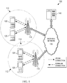
- FIG. 1 illustrates a network 100 for communicating data.
- the network 100 comprises a plurality of access points (APs) 110 each having a coverage area 112, a plurality of user equipment (UEs) 120, a backhaul network 130, and a mobility computation system 140.
- AP may also be referred to as a transmission point (TP), a base station (BS), or a base transceiver station (BTS), and the terms may be used interchangeably throughout this disclosure.
- TP transmission point
- BS base station
- BTS base transceiver station
- These coverage areas represent the range of each AP 110 to adequately transmit data, and the coverage areas of adjacent APs 110 may have some overlap 114 in order to accommodate handoffs between APs 110 whenever a UE 120 exits one coverage area 112 and enters an adjacent coverage area 112.
- the AP 110 may comprise any component capable of providing wireless access by, inter alia, establishing uplink (dashed line) and/or downlink (dotted line) connections with the UEs 120, such as a base transceiver station (BTS), an enhanced base station (eNB), a femtocell, and other wirelessly enabled devices.
- the UEs 120 may comprise any component capable of establishing a wireless connection with the AP 110.
- the a UE 120 may be a smartphone, a laptop computer, a tablet computer, a wireless telephone, etc.
- the UEs 120 may also be referred to as wireless devices, mobile devices, or wireless mobile devices.
- the backhaul network 130 may be any component or collection of components that allow data to be exchanged between the AP 110 and a remote end (not shown).
- the network 100 may comprise various other wireless devices, such as relays, femtocells, etc.
- the mobility computation system 140 negotiates with UEs 120 to establish a common mobility prediction algorithm, parameters for determining the location, and parameters for determining when the UE should report its location.
- the common mobility prediction algorithm is to be used by the respective UE 120 and the mobility computation system 140 in determining the location of the UE.
- the UE 120 and the mobility computation system 140 enter a training phase to allow the mobility prediction algorithm to have sufficient data points to determine a predicted UE 120 location. After the training phase, the UE 120 does not report its location except when a condition or criteria negotiated by the UE 120 and the mobility computation system 140 has been met.
- Figure 2 illustrates a timing diagram for a protocol 200 for mobility prediction policy negotiation and location estimation.
- the protocol 200 may include a UE 202 exchanging messages with a system 204.
- UE 200 may be substantially similar to UE 120 in Figure 1 .
- System 204 may be substantially similar to the mobility computation system 140 depicted in Figure 1 .
- the UE 202 and the system 204 enter a negotiation phase 206 in which the UE 202 and the system 204 exchange mobility policy service negotiation messages 208 to agree on a location prediction algorithm, number of location information points to provide for a training period 212, and the criteria or conditions for the UE 202 to report actual location information to the system 204 after the UE 202 and the system 204 have entered a prediction period.
- the system 204 sends the UE 202 a location request 210 to which the UE reports with one or more messages 214 providing location information points and timestamps to the system 204 during a training period 212.
- both the UE 202 and the system 204 run the same mobility prediction algorithm 216 during the prediction period 218.
- the UE 202 periodically or occasionally determines whether a reporting 220 condition has been met indicating that the UE 202 should report its actual location and timestamp information to the system 204. If the condition has not been met, then the UE 202 does not transmit actual location and timestamp information to the system 204 and the system 204 assumes that the predicted location from the mobility prediction algorithm 216 is the actual location of the UE 202.
- the UE 220 sends one or more messages 222 to the system 204 reporting its current location and timestamp information as well as possibly a pre-specified number of previous location and timestamp points. Both the UE 202 and the system 204 then enter a mobility prediction and correction phase 224 to update the prediction algorithm, after which, both the UE 202 and the system 224 re-enter the prediction period in which the UE 202 only reports its actual location to the system 204 if the reporting condition 220 is met. Otherwise, the system 224 assumes that the predicted location is the actual location.
- the reporting condition is that the UE 202 determines that the predicted location and the actual location exceed a predefined maximum variation.
- Figure 3 illustrates an embodiment system 300 for providing online UE mobility prediction.
- the system 300 includes a pool 308 of mobility prediction tools and their parameter sets to choose from. Both the mobility computation system and the UE negotiate 302 based on a number of factors 304.
- the first factor 304 includes the UE requirements, such as the battery condition of a UE device, the computational capability of the device, the reliability of its GPS, etc.
- the second factor 304 includes pricing information. Suppose UE mobility prediction becomes a mandatory function for any services. How mobility prediction is performed depends on the pricing information. For example, a UE may pay more for the same service if he reports its location information less frequent than the others.
- the third factor 304 includes mobility data. Location databases are readily available and points of interest such as roadway conditions can be used for the mobility predictor (and its parameter) selection. For example, driving on a highway would generally require less location samples for prediction compared to driving in a city.
- the fourth factor 304 includes network conditions. A UE located near a cell edge might require more power to report its location information.
- the fifth factor 304 includes design objectives.
- the objectives of mobility prediction may also be part of a negotiation process.
- the objectives may include message reduction, neighbor discovering, power consumption reduction, cost reduction, etc.
- the two parties then agree 310 to use the same mobility predictor selected from the pool 308, what parameters of this mobility predictor are used, what a mobility predictor training mechanism would be, how mobility estimation error is handled, and/or how re-negotiation is triggered.
- a simplified autoregressive AR(p) model is be used for mobility prediction.
- the speed and direction can be computed as follows. Denote ⁇ i as the direction, s i is the speed at time slot I, and T is the duration spent travelling.
- Both the direction and the speed at time slot i+1, ⁇ i + 1 and s ⁇ i +1 , respectively, can be estimated using the proposed AR model.
- a standard continuous transformation on the direction is applied.
- the system may alter the predictor, for example by increasing the number of samples needed for the predictor on the fly.
- FIG. 4 illustrates a flowchart of an embodiment of a method 400 for negotiating a mobility prediction algorithm and implementing mobility prediction.
- the method 400 begins at block 402 where the UE and the wireless service system exchange information and negotiate and agree upon algorithm for location prediction, parameters to measure, and conditions upon which the UE should report actual location information the system.
- the UE reports its location information with timestamps to the mobility prediction system during a training period in order that the mobility prediction system has sufficient information to predict the UEs location at a given time.
- both the UE and the system run the same mobility prediction algorithm (to which they both agreed during the negotiation phase) in parallel to predict the next location of the UE at time t.
- the UE determines whether the condition has been met for reporting the UE's actual location. If yes, then the method 400 proceeds to block 410 where the UE reports its current location information and possibly a number of previous location information with timestamps to the mobility prediction system and both the UE and the system correct an estimation error, after which, the method proceeds to block 406. If, at block 408, the condition is not met, then the method 400 proceeds to block 412 where both the system and the UE assume that its predicted UE location at time t is correct. The method 400 then proceeds to block 414 where it is determined whether to end mobility prediction (e.g., the UE is powered off). If mobility prediction is continued at block 414, then the method proceeds to block 406. Otherwise, the method 400 ends.
- end mobility prediction e.g., the UE is powered off
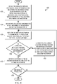
- FIG. 5 illustrates a flowchart of another embodiment of a method 500 for negotiating a mobility prediction algorithm and implementing mobility prediction.
- the method 500 begins at block 502 where the UE and the mobility prediction system agree on a mobility prediction algorithm and the UE reports its location information with timestamps to the mobility prediction system all at once at the end of the training phase.
- both the UE and the mobility prediction system runs the same mobility prediction algorithm in parallel to predict the next location of the UE at time t.
- the UE determines whether the difference between an estimated location and an actual location at time t is within (i.e., less than) a predefined threshold (e.g., within 10 meters).
- a predefined threshold e.g., within 10 meters.
- the method 500 proceeds to block 508 where the UE reports its current location information and possibly the previous (p-1) location information (so that the mobility prediction system has sufficient information to perform the agreed upon mobility prediction algorithm) with timestamps to the mobility prediction system and both the UE and the mobility prediction system correct an estimation error, after which the method 500 proceeds to block 504. If, at block 506, the difference is less than the predefined threshold, then the method 500 proceeds to block 510 where both the UE and the system assume that its predicted UE location at time t is accurate. The method 500 then proceeds to block 512 and determine whether to end mobility prediction (e.g., the UE is powering down). If, at block 512, mobility prediction is not ended, then the method 500 proceeds to block 504. If, at block 512, the mobility prediction is ended, then the method 500 ends.
- end mobility prediction e.g., the UE is powering down
- Figure 6 illustrates a flowchart of another embodiment of a method 600 for negotiating a mobility prediction algorithm and implementing mobility prediction.
- the method 600 begins at block 602 where the UE and the mobility prediction system agree on an algorithm and the UE reports its location information with timestamps to the network mobility prediction system regularly (e.g., at periodic intervals) during the training phase rather than all at once as shown in Figure 5 .
- the remainder of method 600 i.e., blocks 604, 606, 608, 610, and 612 are substantially similar to their corresponding blocks in method 500 (i.e., blocks 504, 506, 508, 510, and 512).
- Figure 7 is a chart 700 illustrating a comparison of the actual path (lighter shading) and the estimated path (darker shading) for a UE during a performance test.
- the performance was evaluated with an AR mobility predictor as described above.
- Chart 700 shows a comparison of the actual path (indicated with circles and lighter shading) and the estimated path (indicated with triangles and darker shading). From the chart 700, it can be seen that the predicted path is close to the actual path.
- Figure 8 illustrates a graph 800 of different in actual location compared to estimated location for the simulation described in above versus a cumulative distribution function (CDF). From graph 800, the amount of overhead incurred to enable the disclosed mobility prediction can be obtained.
- the threshold was set to 5 meters and in only about 10% of the time does a UE need to perform the location information reporting, thereby reducing the overhead on the wireless network.
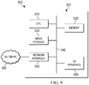
- FIG. 9 is a block diagram of a processing system 900 that may be used for implementing the devices and methods disclosed herein. Specific devices may utilize all of the components shown, or only a subset of the components, and levels of integration may vary from device to device. Furthermore, a device may contain multiple instances of a component, such as multiple processing units, processors, memories, transmitters, receivers, etc.
- the processing system 900 comprises a processing unit 901 equipped with one or more input/output devices, such as a speaker, microphone, mouse, touchscreen, keypad, keyboard, printer, display, and the like.
- the processing unit 901 may include a central processing unit (CPU) 910, memory 920, a mass storage device 930, a network interface 950, and an I/O interface 960 connected to a bus 940.
- the bus 940 may be one or more of any type of several bus architectures including a memory bus or memory controller, a peripheral bus, video bus, or the like.
- the CPU 910 may comprise any type of electronic data processor.
- the memory 920 may comprise any type of system memory such as static random access memory (SRAM), dynamic random access memory (DRAM), synchronous DRAM (SDRAM), read-only memory (ROM), a combination thereof, or the like.
- the memory 920 may include ROM for use at boot-up, and DRAM for program and data storage for use while executing programs.
- the mass storage device 930 may comprise any type of storage device configured to store data, programs, and other information and to make the data, programs, and other information accessible via the bus 940.
- the mass storage device 930 may comprise, for example, one or more of a solid state drive, hard disk drive, a magnetic disk drive, an optical disk drive, or the like.
- the I/O interface 960 may provide interfaces to couple external input and output devices to the processing unit 901.
- the I/O interface 960 may include a video adapter. Examples of input and output devices may include a display coupled to the video adapter and a mouse/keyboard/printer coupled to the I/O interface. Other devices may be coupled to the processing unit 901, and additional or fewer interface cards may be utilized. For example, a serial interface such as Universal Serial Bus (USB) (not shown) may be used to provide an interface for a printer.
- USB Universal Serial Bus
- the processing unit 901 may also include one or more network interfaces 950, which may comprise wired links, such as an Ethernet cable or the like, and/or wireless links to access nodes or different networks.
- the network interface 901 allows the processing unit to communicate with remote units via the networks 980.
- the network interface 950 may provide wireless communication via one or more transmitters/transmit antennas and one or more receivers/receive antennas.
- the processing unit 901 is coupled to a local-area network or a wide-area network for data processing and communications with remote devices, such as other processing units, the Internet, remote storage facilities, or the like.
Landscapes
- Engineering & Computer Science (AREA)
- Physics & Mathematics (AREA)
- General Physics & Mathematics (AREA)
- Radar, Positioning & Navigation (AREA)
- Remote Sensing (AREA)
- Computer Networks & Wireless Communication (AREA)
- Signal Processing (AREA)
- Mobile Radio Communication Systems (AREA)
Description
- The present invention relates to a system and method for wireless communications, and, in particular embodiments, to a system and method for user equipment mobility prediction.
- The location of a mobile wireless device in a wireless network may be important for a variety of applications, such as providing maps and directions to users. The location may also be important in order to provide directions for emergency personal should the user of the mobile wireless device need assistance. Other applications, such as traffic reporting, weather reports, identity of nearby restaurants, stores, and cinemas may also depend on the location of the mobile wireless device. Different applications may have different requirements for the level of precision with which the mobile wireless device's location must be determined. A number of mechanisms have been developed for determining the actual location of a wireless device. However, these mechanisms often require the wireless device to report its location to the network frequently, thereby using up network resources.
-
WO 2009/019672 A1 ,US 2007/0049289 A1 ,GB 2277844 A WO 00/72619 A1 - Aspects of the invention are provided in the attached claims.
- For a more complete understanding of the present invention, and the advantages thereof, reference is now made to the following descriptions taken in conjunction with the accompanying drawing, in which:
-
Figure 1 illustrates a network for communicating data; -
Figure 2 illustrates a protocol diagram for an embodiment of a system for mobility prediction policy negotiation and location estimation; -
Figure 3 illustrates an embodiment system for providing online UE mobility prediction; -
Figure 4 illustrates a flowchart of an embodiment of a method for negotiating a mobility prediction algorithm and implementing mobility prediction; -
Figure 5 illustrates a flowchart of another embodiment of a method for negotiating a mobility prediction algorithm and implementing mobility prediction; -
Figure 6 illustrates a flowchart of another embodiment of a method for negotiating a mobility prediction algorithm and implementing mobility prediction; -
Figure 7 is a chart illustrating a comparison of the actual path (lighter shading) and the estimated path (darker shading) for a UE during a performance test; -
Figure 8 illustrates a graph of the difference in actual location compared to estimated location for a performance test versus a cumulative distribution function (CDF); and -
Figure 9 is a processing system that can be used to implement various embodiments. - The making and using of the presently preferred embodiments are discussed in detail below. It should be appreciated, however, that the present invention provides many applicable inventive concepts that can be embodied in a wide variety of specific contexts. The specific embodiments discussed are merely illustrative of specific ways to make and use the invention, and do not limit the scope of the invention.
- In wireless networks, UE mobility is one of the challenging issues for effective resource management. Imagine a driver who requests a service with tight quality of service (QoS) constraints might be going into a long tunnel very soon, where there will be no signal coverage. With this knowledge, the system should generally not admit this service as the system will not be able to provide enough capacity to satisfy the QoS requirements of this service. Besides service admission, mobility management is also used for other resource allocation domains such as flow control, routing, packet scheduling, etc. An embodiment provides a mobility management solution for service admission. The embodiment methodology can be applied to other resource allocation areas such as routing, flow control, etc.
- In an embodiment, the UE and the system exchange messages with each other to negotiate a mobility prediction protocol. The mobility prediction protocol specifies a mobility predictor to be used by both the UE and the system in parallel with each other. The mobility prediction protocol also specifies the parameters that the UE will provide to the system (e.g., a location and time stamps for a specified number of previous locations for the UE) for training the mobility predictor. The locations and timestamps are used by the UE and the system to train the mobility predictor so that both the UE and the system predict the same location for a given time. The mobility prediction protocol also specifies the condition(s) upon which the UE will report its actual location to the system. After the training period, the UE only reports its actual location to the system if the condition(s) for reporting are satisfied. Otherwise, the UE will refrain from transmitting actual location information and the system assumes that its predicted location for the UE is the actual location for the UE. In an embodiment, the mobile location may be defined as an absolute location (e.g., geographic location - longitude and latitude), a location relative to the network infrastructure (e.g., received radio signal strength from network radio nodes, pathloss, average signal to noise ratio (SNR), etc.), or location relative to one or more nearby landscape references (e.g., buildings, constructions, bridges, roads, parks, recreation areas, etc.). In an embodiment, whenever the UE reports to the system, the mobile report content may include any type of location as defined above, current and/or historical locations of the mobile device, information on a route plan (if available, such as a GPS plan), and predictor-specific data associated with location information. The location reported to the system may be as a change in reference to a previous report (e.g., 10 meters north of last location).
- An embodiment provides a simple system to enable online mobility prediction where the UE only reports location information when needed (e.g., an estimation error exceeds a certain threshold, a change in direction of the UE from a previous direction of travel exceeds a threshold, a change in the speed of travel of the UE exceeds a threshold, the conditions through which the UE is about to travel through or have travelled through require an update (e.g., the UE is about to enter a tunnel or has exited a tunnel), etc.). The system also enables fast adaptation to any changes on the fly. Resources can be better allocated with more accurate UE mobility. Admission control could admit more users given the accurate mobility patterns of already admitted UEs. Handover performance and hence quality of experience (QoE) can be improved. Routing can select a better route with accurate mobility information. It can be combined with other historical statistics for better mobility prediction. Knowing UE locations accurately can help result in better resource utilization to improve service admission performance, handover/routing performance, etc.
- An embodiment estimates the location of the UE at any given time. Time is divided into a training phase and a prediction phase. In the training phase, the UE reports its location information with timestamps to the system. Both the UE and the system run the same algorithm to train a mobility predictor.
- In an embodiment, the prediction scheme is an on-demand per user or per application customized mobility prediction scheme. The predictor algorithm, the report content, and the report period can be negotiated on a per user basis, per session bases, per application basis, or based on one or more of UE equipment capability/battery, application quality of service (QoS), and network topology (denser deployment or not, etc.)
- In the prediction phase, both the UE and the network run the same type of predictor or algorithm. The UE reports its current and past actual location information if a condition is met., The condition may be an event driven occurrence (e.g., the estimated location and the actual location is off more than the threshold) or periodically, as agreed. For example, if the estimated location and the actual location are within a threshold, the UE does not report to the system and the system assumes the estimated location is accurate. If the estimated location and the actual location are off more than the threshold, the UE reports its current location information (and previous location information) with timestamps to the system. Both the UE and the system correct the errors in parallel.
- An embodiment protocol enables policy-based UE location estimation and prediction having two phases, a mobility prediction policy negotiation, and a UE location estimation and prediction. In the mobility prediction policy negotiation phase, the system and the UE negotiate a mobility prediction policy, which includes a mobility prediction algorithm, parameters for the mobility prediction algorithm, and a mobility prediction correction mechanism. In the UE location estimation and prediction phase, both the UE and the system, first train the same mobility predictor according to the negotiated policy. Second, they estimate and predict the UE locations, and correct the mobility predictor based on the policy. This protocol also allows dynamic mobility prediction policy negotiations between the UE and the system on the fly.
- In an embodiment, the mobility protocol also includes an error correction phase. If the condition for reporting actual location is met, the UE transmits location and timestamp data for a plurality of previous locations and times to retrain (e.g., correct location errors) the mobility predictor on both the system and the UE. After the mobility predictor on both the UE and the system have been retrained, the UE and the system re-enter the prediction phase in which the UE does not report actual location information unless the condition for reporting is met. Some radio reception information from the detection of the radio signal carrying the report information from the UE could be used for the purpose of correcting the measurement accuracy of the mobile device location.
- In an embodiment, the UE and the system renegotiate the mobility predictor and parameters. The condition for renegotiating a new mobility predictor and parameters be specified in the original agreed upon mobility predictor and parameters or be initiated by either the UE or the system. For example, if network conditions change, the system initiates a new negotiation with the UE. For example, if network conditions have improved, the UE and the system agree on new reporting conditions that may occur more frequently thereby making use of the improved network conditions. Alternatively, if the network conditions have denigrated, the system and the UE may agree on reporting conditions that are less likely to occur and thereby place fewer demands on the network.
- In an embodiment, the UE requests to renegotiate the mobility predictor and parameters due to changes in the state of the UE (e.g., battery status, computational power, etc.). For example, if the UE's battery is low, the UE may negotiate a condition for reporting that may occur less frequently (e.g., by specifying a larger difference between the actual and predicted location before reporting) so as to conserve battery resources. If other applications on the UE are making greater demands on the computational power of the UE, the UE may wish to negotiate a new mobility predictor that is less computationally intensive than the one currently running.
- In an embodiment, mobility prediction policy negotiation includes messages that are exchanged to determine which mobility predictor to use, which parameters are used, and under what conditions a UE should report.
- A location information request is sent from the system to a UE. In the training period, a UE reports a number of location information samples to the system so that both the system and the UE can have the same trained mobility predictor.
- Samples of location information are sent from a UE to the system. In the prediction phase, a UE sends a number of actual location information samples or elements from which can be deduced the actual location information samples (e.g., pathloss) to the system so that both the UE and the system can correct the mobility predictor in exactly the same manner.
-
FIG. 1 illustrates anetwork 100 for communicating data. Thenetwork 100 comprises a plurality of access points (APs) 110 each having acoverage area 112, a plurality of user equipment (UEs) 120, abackhaul network 130, and amobility computation system 140. As used herein, the term AP may also be referred to as a transmission point (TP), a base station (BS), or a base transceiver station (BTS), and the terms may be used interchangeably throughout this disclosure. These coverage areas represent the range of eachAP 110 to adequately transmit data, and the coverage areas ofadjacent APs 110 may have someoverlap 114 in order to accommodate handoffs betweenAPs 110 whenever aUE 120 exits onecoverage area 112 and enters anadjacent coverage area 112. TheAP 110 may comprise any component capable of providing wireless access by, inter alia, establishing uplink (dashed line) and/or downlink (dotted line) connections with theUEs 120, such as a base transceiver station (BTS), an enhanced base station (eNB), a femtocell, and other wirelessly enabled devices. TheUEs 120 may comprise any component capable of establishing a wireless connection with theAP 110. For example, the aUE 120 may be a smartphone, a laptop computer, a tablet computer, a wireless telephone, etc. TheUEs 120 may also be referred to as wireless devices, mobile devices, or wireless mobile devices. Thebackhaul network 130 may be any component or collection of components that allow data to be exchanged between theAP 110 and a remote end (not shown). In some embodiments, thenetwork 100 may comprise various other wireless devices, such as relays, femtocells, etc. - The
mobility computation system 140 negotiates withUEs 120 to establish a common mobility prediction algorithm, parameters for determining the location, and parameters for determining when the UE should report its location. The common mobility prediction algorithm is to be used by therespective UE 120 and themobility computation system 140 in determining the location of the UE. TheUE 120 and themobility computation system 140 enter a training phase to allow the mobility prediction algorithm to have sufficient data points to determine a predictedUE 120 location. After the training phase, theUE 120 does not report its location except when a condition or criteria negotiated by theUE 120 and themobility computation system 140 has been met. -
Figure 2 illustrates a timing diagram for aprotocol 200 for mobility prediction policy negotiation and location estimation. Theprotocol 200 may include aUE 202 exchanging messages with asystem 204.UE 200 may be substantially similar toUE 120 inFigure 1 .System 204 may be substantially similar to themobility computation system 140 depicted inFigure 1 . Initially, theUE 202 and thesystem 204 enter anegotiation phase 206 in which theUE 202 and thesystem 204 exchange mobility policyservice negotiation messages 208 to agree on a location prediction algorithm, number of location information points to provide for atraining period 212, and the criteria or conditions for theUE 202 to report actual location information to thesystem 204 after theUE 202 and thesystem 204 have entered a prediction period. After theUE 202 and thesystem 204 have agreed upon the prediction algorithm and other information, thesystem 204 sends the UE 202 alocation request 210 to which the UE reports with one ormore messages 214 providing location information points and timestamps to thesystem 204 during atraining period 212. - Once the
training period 212 has expired, both theUE 202 and thesystem 204 run the samemobility prediction algorithm 216 during theprediction period 218. TheUE 202 periodically or occasionally determines whether a reporting 220 condition has been met indicating that theUE 202 should report its actual location and timestamp information to thesystem 204. If the condition has not been met, then theUE 202 does not transmit actual location and timestamp information to thesystem 204 and thesystem 204 assumes that the predicted location from themobility prediction algorithm 216 is the actual location of theUE 202. If the condition for reporting 220 has been met, then theUE 220 sends one ormore messages 222 to thesystem 204 reporting its current location and timestamp information as well as possibly a pre-specified number of previous location and timestamp points. Both theUE 202 and thesystem 204 then enter a mobility prediction andcorrection phase 224 to update the prediction algorithm, after which, both theUE 202 and thesystem 224 re-enter the prediction period in which theUE 202 only reports its actual location to thesystem 204 if thereporting condition 220 is met. Otherwise, thesystem 224 assumes that the predicted location is the actual location. In an embodiment, the reporting condition is that theUE 202 determines that the predicted location and the actual location exceed a predefined maximum variation. -
Figure 3 illustrates anembodiment system 300 for providing online UE mobility prediction. Thesystem 300 includes apool 308 of mobility prediction tools and their parameter sets to choose from. Both the mobility computation system and the UE negotiate 302 based on a number offactors 304. - The
first factor 304 includes the UE requirements, such as the battery condition of a UE device, the computational capability of the device, the reliability of its GPS, etc. Thesecond factor 304 includes pricing information. Suppose UE mobility prediction becomes a mandatory function for any services. How mobility prediction is performed depends on the pricing information. For example, a UE may pay more for the same service if he reports its location information less frequent than the others. Thethird factor 304 includes mobility data. Location databases are readily available and points of interest such as roadway conditions can be used for the mobility predictor (and its parameter) selection. For example, driving on a highway would generally require less location samples for prediction compared to driving in a city. Thefourth factor 304 includes network conditions. A UE located near a cell edge might require more power to report its location information. Or, if a cell is overloaded, requiring every UE in its cell to report their locations frequently might not be feasible. Thefifth factor 304 includes design objectives. The objectives of mobility prediction may also be part of a negotiation process. The objectives may include message reduction, neighbor discovering, power consumption reduction, cost reduction, etc. - The two parties then agree 310 to use the same mobility predictor selected from the
pool 308, what parameters of this mobility predictor are used, what a mobility predictor training mechanism would be, how mobility estimation error is handled, and/or how re-negotiation is triggered. - As an example, for mobility prediction, a simplified autoregressive AR(p) model is be used. However, other mobility prediction algorithms may also be used. The AR(p) model is given as follows (ignoring a random noise term):

- The estimation error is denoted as ek = z̃k - z̃k. A mobility predictor may be built as follows: Initialize all the AR coefficients:

- Notice that these weights wj's can be obtained through online or offline training.
- Update the coefficients starting from j=1 to j=p:

- Update the constant c:

- Use this predictor to predict the speed and the direction of a UE. Given two sets of xy-coordinates, the speed and direction can be computed as follows. Denote θi as the direction, si is the speed at time slot I, and T is the duration spent travelling. Thus,


- Both the direction and the speed at time slot i+1, θ̃ i+1 and s̃ i+1, respectively, can be estimated using the proposed AR model. A standard continuous transformation on the direction is applied. With the estimates, the xy-coordinates can be predicted as follows:


- The system may alter the predictor, for example by increasing the number of samples needed for the predictor on the fly.
-
Figure 4 illustrates a flowchart of an embodiment of amethod 400 for negotiating a mobility prediction algorithm and implementing mobility prediction. Themethod 400 begins atblock 402 where the UE and the wireless service system exchange information and negotiate and agree upon algorithm for location prediction, parameters to measure, and conditions upon which the UE should report actual location information the system. Atblock 404, the UE reports its location information with timestamps to the mobility prediction system during a training period in order that the mobility prediction system has sufficient information to predict the UEs location at a given time. Atblock 406, both the UE and the system run the same mobility prediction algorithm (to which they both agreed during the negotiation phase) in parallel to predict the next location of the UE at time t. Atblock 408, the UE determines whether the condition has been met for reporting the UE's actual location. If yes, then themethod 400 proceeds to block 410 where the UE reports its current location information and possibly a number of previous location information with timestamps to the mobility prediction system and both the UE and the system correct an estimation error, after which, the method proceeds to block 406. If, atblock 408, the condition is not met, then themethod 400 proceeds to block 412 where both the system and the UE assume that its predicted UE location at time t is correct. Themethod 400 then proceeds to block 414 where it is determined whether to end mobility prediction (e.g., the UE is powered off). If mobility prediction is continued atblock 414, then the method proceeds to block 406. Otherwise, themethod 400 ends. -
Figure 5 illustrates a flowchart of another embodiment of amethod 500 for negotiating a mobility prediction algorithm and implementing mobility prediction. Themethod 500 begins atblock 502 where the UE and the mobility prediction system agree on a mobility prediction algorithm and the UE reports its location information with timestamps to the mobility prediction system all at once at the end of the training phase. Atblock 504, both the UE and the mobility prediction system runs the same mobility prediction algorithm in parallel to predict the next location of the UE at time t. Atblock 506, the UE determines whether the difference between an estimated location and an actual location at time t is within (i.e., less than) a predefined threshold (e.g., within 10 meters). If, atblock 506, the difference is greater than the predefined threshold, then themethod 500 proceeds to block 508 where the UE reports its current location information and possibly the previous (p-1) location information (so that the mobility prediction system has sufficient information to perform the agreed upon mobility prediction algorithm) with timestamps to the mobility prediction system and both the UE and the mobility prediction system correct an estimation error, after which themethod 500 proceeds to block 504. If, atblock 506, the difference is less than the predefined threshold, then themethod 500 proceeds to block 510 where both the UE and the system assume that its predicted UE location at time t is accurate. Themethod 500 then proceeds to block 512 and determine whether to end mobility prediction (e.g., the UE is powering down). If, atblock 512, mobility prediction is not ended, then themethod 500 proceeds to block 504. If, atblock 512, the mobility prediction is ended, then themethod 500 ends. -
Figure 6 illustrates a flowchart of another embodiment of amethod 600 for negotiating a mobility prediction algorithm and implementing mobility prediction. Themethod 600 begins atblock 602 where the UE and the mobility prediction system agree on an algorithm and the UE reports its location information with timestamps to the network mobility prediction system regularly (e.g., at periodic intervals) during the training phase rather than all at once as shown inFigure 5 . The remainder of method 600 (i.e., blocks 604, 606, 608, 610, and 612) are substantially similar to their corresponding blocks in method 500 (i.e., blocks 504, 506, 508, 510, and 512). -
Figure 7 is a chart 700 illustrating a comparison of the actual path (lighter shading) and the estimated path (darker shading) for a UE during a performance test. The performance was evaluated with an AR mobility predictor as described above. The simulation parameters included: - Topology: 250m x 250m
- Simulation time: 20,000 seconds
- UE mobility model: random waypoint
- ∘ Speed: uniform on (0.2, 2.2) m/s
- ∘ Pause: uniform on (0, 1) s
- ∘ Walk: uniform on (2, 6) s
- ∘ Direction: uniform on (-180, 180) degrees
- Simplified AR(5)
- UE reports if the distance between an estimated location and an actual location is more than 5 meters.
- Chart 700 shows a comparison of the actual path (indicated with circles and lighter shading) and the estimated path (indicated with triangles and darker shading). From the chart 700, it can be seen that the predicted path is close to the actual path.
-
Figure 8 illustrates agraph 800 of different in actual location compared to estimated location for the simulation described in above versus a cumulative distribution function (CDF). Fromgraph 800, the amount of overhead incurred to enable the disclosed mobility prediction can be obtained. The threshold was set to 5 meters and in only about 10% of the time does a UE need to perform the location information reporting, thereby reducing the overhead on the wireless network. -
Figure 9 is a block diagram of aprocessing system 900 that may be used for implementing the devices and methods disclosed herein. Specific devices may utilize all of the components shown, or only a subset of the components, and levels of integration may vary from device to device. Furthermore, a device may contain multiple instances of a component, such as multiple processing units, processors, memories, transmitters, receivers, etc. Theprocessing system 900 comprises aprocessing unit 901 equipped with one or more input/output devices, such as a speaker, microphone, mouse, touchscreen, keypad, keyboard, printer, display, and the like. Theprocessing unit 901 may include a central processing unit (CPU) 910,memory 920, amass storage device 930, anetwork interface 950, and an I/O interface 960 connected to abus 940. Thebus 940 may be one or more of any type of several bus architectures including a memory bus or memory controller, a peripheral bus, video bus, or the like. TheCPU 910 may comprise any type of electronic data processor. Thememory 920 may comprise any type of system memory such as static random access memory (SRAM), dynamic random access memory (DRAM), synchronous DRAM (SDRAM), read-only memory (ROM), a combination thereof, or the like. In an embodiment, thememory 920 may include ROM for use at boot-up, and DRAM for program and data storage for use while executing programs. - The
mass storage device 930 may comprise any type of storage device configured to store data, programs, and other information and to make the data, programs, and other information accessible via thebus 940. Themass storage device 930 may comprise, for example, one or more of a solid state drive, hard disk drive, a magnetic disk drive, an optical disk drive, or the like. - The I/
O interface 960 may provide interfaces to couple external input and output devices to theprocessing unit 901. The I/O interface 960 may include a video adapter. Examples of input and output devices may include a display coupled to the video adapter and a mouse/keyboard/printer coupled to the I/O interface. Other devices may be coupled to theprocessing unit 901, and additional or fewer interface cards may be utilized. For example, a serial interface such as Universal Serial Bus (USB) (not shown) may be used to provide an interface for a printer. - The
processing unit 901 may also include one ormore network interfaces 950, which may comprise wired links, such as an Ethernet cable or the like, and/or wireless links to access nodes or different networks. Thenetwork interface 901 allows the processing unit to communicate with remote units via thenetworks 980. For example, thenetwork interface 950 may provide wireless communication via one or more transmitters/transmit antennas and one or more receivers/receive antennas. In an embodiment, theprocessing unit 901 is coupled to a local-area network or a wide-area network for data processing and communications with remote devices, such as other processing units, the Internet, remote storage facilities, or the like.
Claims (15)
- A method for mobility prediction in a wireless network, the method comprising:negotiating (206) with a mobile device (202) to determine a mobility prediction policy to be implemented on both the mobile device and a mobility prediction server, the mobility prediction policy comprising a mobility predictor selected from a predetermined pool of mobility predictors, parameters for the mobility predictor, a condition for reporting a location, and a condition for renegotiating a new mobility predictor and parameters, wherein the negotiating comprises receiving at least one message from the mobile device and sending at least one message to the mobile device to agree on a mobility prediction policy based on one or more factors, the factors comprising mobile device requirements, pricing information, mobility data availability, network conditions, and design objectives;receiving (214) at least one actual location and timestamp from the mobile device during a training period according to the mobility prediction policy so as to train the mobility predictor;using the mobility predictor to predict the location of the mobile device after the training period when the condition for reporting a location is not met;receiving (222) actual location information and previous location information from the mobile device after the training period only when the condition for reporting a location is met; andrenegotiating with the mobile device a new mobility predictor and parameters when the condition for renegotiating is met.
- The method of claim 1, wherein the mobility prediction policy specifies at least one condition for which the mobile device will transmit an actual location after an expiration of the training period.
- The method of claim 2, wherein the at least one condition comprises determining whether a difference between the actual location of the mobile device from a predicted location of the mobile device exceeds a threshold value.
- The method of claim 2, wherein the at least one condition comprises determining whether a change in at least one of a direction and a speed of the mobile device exceeds a threshold value.
- The method of claim 2, wherein the at least one condition comprises at least one of an event trigger and a reporting period.
- The method of claim 1, further comprising determining (216) a predicted location of the mobile device using the mobility prediction policy.
- The method of claim 6, further comprising setting a predicted location for the mobile device at a time as the actual location for the mobile device at the time when failing to receive a location report from the mobile device.
- The method of claim 6, further comprising correcting (224) an error in the predicted location after receiving actual location information from the mobile device after an end of the training period.
- The method of claim 1, wherein the location comprises as an absolute geographic location, or a relative location, wherein the relative location is described relative to one of network infrastructure and a nearby landscape reference.
- The method of claim 9, wherein the relative location is determined relative to one of a received radio signal strength from network radio nodes, pathloss, and an average signal to noise ratio.
- The method of claim 1, wherein the actual location information comprises at least one of an absolute location, a location relative to network infrastructure, a location relative to a landscape feature, current location, a historical location, information on a route plan, predictor specific data associated with the location, and location information relative to a previous location.
- The method of claim 1, wherein the negotiation comprises an on-demand negotiation per user or per application of a customized mobility prediction scheme.
- The method of claim 1, wherein the mobility prediction policy is based on at least one of user equipment capability, user equipment battery type, application quality of service, and network topology.
- The method of claim 1, wherein radio reception information from a detection of a radio signal carrying the actual location information from the mobile device received after the training period is used to correct measurement accuracy of the location of the mobile device.
- A network component configured for mobility prediction in a wireless network, comprising:a processor; anda computer readable storage medium storing programming for execution by the processor, the programming including instructions to implement actions in a method in accordance with any one of claims 1 to 14.
Applications Claiming Priority (3)
| Application Number | Priority Date | Filing Date | Title |
|---|---|---|---|
| US201261737602P | 2012-12-14 | 2012-12-14 | |
| US13/839,830 US9686769B2 (en) | 2012-12-14 | 2013-03-15 | Systems and methods for user equipment mobility prediction |
| PCT/CN2013/089503 WO2014090198A1 (en) | 2012-12-14 | 2013-12-16 | Systems and methods for user equipment mobility prediction |
Publications (3)
| Publication Number | Publication Date |
|---|---|
| EP2932774A1 EP2932774A1 (en) | 2015-10-21 |
| EP2932774A4 EP2932774A4 (en) | 2015-11-18 |
| EP2932774B1 true EP2932774B1 (en) | 2021-02-10 |
Family
ID=50931506
Family Applications (1)
| Application Number | Title | Priority Date | Filing Date |
|---|---|---|---|
| EP13863633.7A Active EP2932774B1 (en) | 2012-12-14 | 2013-12-16 | Systems and methods for user equipment mobility prediction |
Country Status (4)
| Country | Link |
|---|---|
| US (1) | US9686769B2 (en) |
| EP (1) | EP2932774B1 (en) |
| CN (1) | CN104838708B (en) |
| WO (1) | WO2014090198A1 (en) |
Families Citing this family (22)
| Publication number | Priority date | Publication date | Assignee | Title |
|---|---|---|---|---|
| US9107132B2 (en) * | 2013-04-24 | 2015-08-11 | International Business Machines Corporation | Trajectory-aware location-based hand-offs |
| US10009794B2 (en) | 2013-12-05 | 2018-06-26 | Huawei Technologies Co., Ltd. | Framework for traffic engineering in software defined networking |
| US9485689B2 (en) | 2014-01-06 | 2016-11-01 | Huawei Technologies Co., Ltd. | Adaptive traffic engineering configuration |
| US9380487B2 (en) * | 2014-07-29 | 2016-06-28 | Huawei Technologies Co., Ltd. | System and method for a location prediction-based network scheduler |
| US11805467B2 (en) * | 2015-03-25 | 2023-10-31 | Comcast Cable Communications, Llc | Distributed content delivery for moving devices |
| EP4161132A1 (en) * | 2016-07-04 | 2023-04-05 | Motorola Mobility LLC | Analytics-based policy generation |
| US11475777B2 (en) * | 2017-09-28 | 2022-10-18 | Lenovo (Beijing) Limited | Method and apparatus for controlling the operation of aerial UEs |
| US11507172B2 (en) | 2017-12-29 | 2022-11-22 | Google Llc | Smart context subsampling on-device system |
| CN110062375B (en) * | 2018-01-19 | 2020-11-06 | 电信科学技术研究院有限公司 | Information processing method and device, and computer storage medium |
| EP3794847A4 (en) | 2018-06-07 | 2021-06-23 | Huawei Technologies Co., Ltd. | Method of mobility based on prediction and pre-preparation |
| US11178156B2 (en) * | 2018-07-27 | 2021-11-16 | Verizon Patent And Licensing Inc. | Methods and systems for authenticating a reported geolocation of a mobile device |
| US10924560B2 (en) * | 2018-07-30 | 2021-02-16 | Facebook, Inc. | Determining geographic locations of network devices |
| CN109041217B (en) * | 2018-09-21 | 2020-01-10 | 北京邮电大学 | Hierarchical mobility prediction method in heterogeneous network |
| CN111629319B (en) * | 2019-02-28 | 2022-05-31 | 中国移动通信有限公司研究院 | Position prediction method and device |
| US11032724B2 (en) | 2019-07-10 | 2021-06-08 | Rohde & Schwarz Gmbh & Co. Kg | System and method for optimizing signal path calibration |
| EP4005157B1 (en) * | 2019-07-30 | 2023-05-24 | Telefonaktiebolaget LM Ericsson (publ) | Ue-assisted data collection for mobility prediction |
| BR112021000527A2 (en) * | 2019-12-10 | 2022-06-21 | Ericsson Telecomunicacoes Sa | Methods, ue and first network node for handling mobility information in a communications network |
| CN111444302B (en) * | 2020-04-17 | 2020-12-18 | 中国传媒大学 | Mobility prediction method, system and device based on user classification |
| CN111523667B (en) * | 2020-04-30 | 2023-06-27 | 天津大学 | RFID positioning method based on neural network |
| US20230300654A1 (en) * | 2020-07-03 | 2023-09-21 | Telefonaktiebolaget Lm Ericsson (Publ) | Methods, UE and Network Node for Failure Predictions |
| US20240040461A1 (en) * | 2020-07-03 | 2024-02-01 | Telefonaktiebolaget Lm Ericsson (Publ) | Ue, network node and methods for handling mobility information in a communications network |
| WO2023069001A1 (en) * | 2021-10-21 | 2023-04-27 | Telefonaktiebolaget Lm Ericsson (Publ) | Reconfiguration procedure in a wireless communication network |
Family Cites Families (12)
| Publication number | Priority date | Publication date | Assignee | Title |
|---|---|---|---|---|
| SG46326A1 (en) | 1993-05-06 | 1998-02-20 | Spectronics Micro Syst Ltd | Improvements in automatic vehicle location system |
| DE19923638C2 (en) | 1999-05-22 | 2002-01-10 | Univ Hannover | Method for managing the location of a mobile terminal in a cellular mobile radio network, cellular mobile radio network and mobile terminal |
| US6611688B1 (en) * | 2000-02-22 | 2003-08-26 | Ericsson Inc. | Position reporting method for a mobile terminal in a mobile communication network |
| KR100651912B1 (en) * | 2005-08-25 | 2006-12-01 | 엘지전자 주식회사 | A location based service system and a position information updating method therefor |
| US7890576B2 (en) * | 2006-11-13 | 2011-02-15 | Microsoft Corporation | Selective communication of targeted information |
| WO2009019672A1 (en) | 2007-08-09 | 2009-02-12 | Mapflow Limited | A transport management system |
| US8391885B2 (en) * | 2009-03-25 | 2013-03-05 | Qualcomm Incorporated | Scheduling location update reports of access terminals to an access network within a wireless communications system |
| CN101820677B (en) | 2010-04-14 | 2013-11-06 | 中兴通讯股份有限公司 | Method for positioning mobile terminal and mobile positioning center |
| US9146296B2 (en) * | 2011-01-14 | 2015-09-29 | Qualcomm Incorporated | Methods and apparatuses for use in providing positioning assistance data to mobile stations via a self-organizing network |
| CN102547833B (en) | 2012-02-22 | 2014-06-18 | 华北电力大学 | Heterogeneous network pre-switching method based on mobile prediction |
| US9654911B2 (en) * | 2012-08-30 | 2017-05-16 | Here Global B.V. | Method and apparatus for providing location sharing via simulation |
| US8922344B2 (en) * | 2012-10-25 | 2014-12-30 | Symbol Technologies, Inc. | Detecting rogue radio frequency based tags based on locationing |
-
2013
- 2013-03-15 US US13/839,830 patent/US9686769B2/en active Active
- 2013-12-16 WO PCT/CN2013/089503 patent/WO2014090198A1/en active Application Filing
- 2013-12-16 EP EP13863633.7A patent/EP2932774B1/en active Active
- 2013-12-16 CN CN201380064322.6A patent/CN104838708B/en active Active
Non-Patent Citations (1)
| Title |
|---|
| None * |
Also Published As
| Publication number | Publication date |
|---|---|
| CN104838708A (en) | 2015-08-12 |
| US20140171106A1 (en) | 2014-06-19 |
| WO2014090198A1 (en) | 2014-06-19 |
| CN104838708B (en) | 2019-02-19 |
| EP2932774A1 (en) | 2015-10-21 |
| EP2932774A4 (en) | 2015-11-18 |
| US9686769B2 (en) | 2017-06-20 |
Similar Documents
| Publication | Publication Date | Title |
|---|---|---|
| EP2932774B1 (en) | Systems and methods for user equipment mobility prediction | |
| Liu et al. | Cooperative offloading and resource management for UAV-enabled mobile edge computing in power IoT system | |
| EP2840836B1 (en) | Method and system for mobile handover management in wireless communication network | |
| Ghosh et al. | Enabling seamless V2I communications: toward developing cooperative automotive applications in VANET systems | |
| US9392508B2 (en) | Methods and systems for admission control and resource availability prediction considering user equipment (UE) mobility | |
| US20130035083A1 (en) | Method and system for proactive and dynamic cross-layer optimization of data transmission to vehicles | |
| Sanghvi et al. | Res6edge: An edge-ai enabled resource sharing scheme for c-v2x communications towards 6g | |
| Rawat et al. | Joint beacon frequency and beacon transmission power adaptation for internet of vehicles | |
| CN116204315A (en) | Track-based dynamic task unloading method for vehicle resource pool in Internet of vehicles | |
| Diamanti et al. | Resource orchestration in uav-assisted noma wireless networks: A labor economics perspective | |
| Evangeline et al. | A two-phase fuzzy based access network selection scheme for vehicular ad hoc networks | |
| US20200400773A1 (en) | Multimodal location sensing on a mobile phone | |
| Vondra et al. | Vehicular network-aware route selection considering communication requirements of users for ITS | |
| Lee et al. | User-centric offloading to WLAN in WLAN/3G vehicular networks | |
| EP3753369A1 (en) | Devices and methods for sidelink resource pool selection based on physical motion | |
| WO2017147771A1 (en) | Processing method, device and system for service optimization | |
| EP4030726B1 (en) | Method of managing a vehicle internet service in a cellular network of at least fourth generation 4g | |
| Chen et al. | An information congestion control scheme in the Internet of Vehicles: A bargaining game approach | |
| Zheng et al. | Data-driven extreme events modeling for vehicle networks by personalized federated learning | |
| Zaki et al. | PLTO: Path Loss-Aware Task Offloading for Vehicular Cooperative Perception | |
| US20230224790A1 (en) | Systems and methods for determining a handover time period based on mobility prediction | |
| EP3209062B1 (en) | Triggering a wireless access point handover | |
| US20240005798A1 (en) | Platooning of communication devices | |
| Rammohan | A Conceptual UAV based Resource Allocation Framework for Next-Generation Heterogeneous V2V Communication Architecture | |
| Wu et al. | Vehicle Selection for C-V2X Mode 4 Based Federated Edge Learning Systems |
Legal Events
| Date | Code | Title | Description |
|---|---|---|---|
| PUAI | Public reference made under article 153(3) epc to a published international application that has entered the european phase |
Free format text: ORIGINAL CODE: 0009012 |
|
| 17P | Request for examination filed |
Effective date: 20150714 |
|
| AK | Designated contracting states |
Kind code of ref document: A1 Designated state(s): AL AT BE BG CH CY CZ DE DK EE ES FI FR GB GR HR HU IE IS IT LI LT LU LV MC MK MT NL NO PL PT RO RS SE SI SK SM TR |
|
| AX | Request for extension of the european patent |
Extension state: BA ME |
|
| A4 | Supplementary search report drawn up and despatched |
Effective date: 20151016 |
|
| RIC1 | Information provided on ipc code assigned before grant |
Ipc: G01S 5/00 20060101ALI20151012BHEP Ipc: H04W 64/00 20090101ALI20151012BHEP Ipc: G01S 5/02 20100101AFI20151012BHEP |
|
| DAX | Request for extension of the european patent (deleted) | ||
| STAA | Information on the status of an ep patent application or granted ep patent |
Free format text: STATUS: EXAMINATION IS IN PROGRESS |
|
| 17Q | First examination report despatched |
Effective date: 20170524 |
|
| GRAP | Despatch of communication of intention to grant a patent |
Free format text: ORIGINAL CODE: EPIDOSNIGR1 |
|
| STAA | Information on the status of an ep patent application or granted ep patent |
Free format text: STATUS: GRANT OF PATENT IS INTENDED |
|
| INTG | Intention to grant announced |
Effective date: 20200915 |
|
| GRAS | Grant fee paid |
Free format text: ORIGINAL CODE: EPIDOSNIGR3 |
|
| GRAA | (expected) grant |
Free format text: ORIGINAL CODE: 0009210 |
|
| STAA | Information on the status of an ep patent application or granted ep patent |
Free format text: STATUS: THE PATENT HAS BEEN GRANTED |
|
| AK | Designated contracting states |
Kind code of ref document: B1 Designated state(s): AL AT BE BG CH CY CZ DE DK EE ES FI FR GB GR HR HU IE IS IT LI LT LU LV MC MK MT NL NO PL PT RO RS SE SI SK SM TR |
|
| REG | Reference to a national code |
Ref country code: GB Ref legal event code: FG4D |
|
| REG | Reference to a national code |
Ref country code: AT Ref legal event code: REF Ref document number: 1360077 Country of ref document: AT Kind code of ref document: T Effective date: 20210215 Ref country code: CH Ref legal event code: EP |
|
| REG | Reference to a national code |
Ref country code: DE Ref legal event code: R096 Ref document number: 602013075607 Country of ref document: DE |
|
| REG | Reference to a national code |
Ref country code: IE Ref legal event code: FG4D |
|
| REG | Reference to a national code |
Ref country code: LT Ref legal event code: MG9D |
|
| REG | Reference to a national code |
Ref country code: NL Ref legal event code: MP Effective date: 20210210 |
|
| PG25 | Lapsed in a contracting state [announced via postgrant information from national office to epo] |
Ref country code: FI Free format text: LAPSE BECAUSE OF FAILURE TO SUBMIT A TRANSLATION OF THE DESCRIPTION OR TO PAY THE FEE WITHIN THE PRESCRIBED TIME-LIMIT Effective date: 20210210 Ref country code: HR Free format text: LAPSE BECAUSE OF FAILURE TO SUBMIT A TRANSLATION OF THE DESCRIPTION OR TO PAY THE FEE WITHIN THE PRESCRIBED TIME-LIMIT Effective date: 20210210 Ref country code: GR Free format text: LAPSE BECAUSE OF FAILURE TO SUBMIT A TRANSLATION OF THE DESCRIPTION OR TO PAY THE FEE WITHIN THE PRESCRIBED TIME-LIMIT Effective date: 20210511 Ref country code: PT Free format text: LAPSE BECAUSE OF FAILURE TO SUBMIT A TRANSLATION OF THE DESCRIPTION OR TO PAY THE FEE WITHIN THE PRESCRIBED TIME-LIMIT Effective date: 20210611 Ref country code: LT Free format text: LAPSE BECAUSE OF FAILURE TO SUBMIT A TRANSLATION OF THE DESCRIPTION OR TO PAY THE FEE WITHIN THE PRESCRIBED TIME-LIMIT Effective date: 20210210 Ref country code: BG Free format text: LAPSE BECAUSE OF FAILURE TO SUBMIT A TRANSLATION OF THE DESCRIPTION OR TO PAY THE FEE WITHIN THE PRESCRIBED TIME-LIMIT Effective date: 20210510 Ref country code: NO Free format text: LAPSE BECAUSE OF FAILURE TO SUBMIT A TRANSLATION OF THE DESCRIPTION OR TO PAY THE FEE WITHIN THE PRESCRIBED TIME-LIMIT Effective date: 20210510 |
|
| REG | Reference to a national code |
Ref country code: AT Ref legal event code: MK05 Ref document number: 1360077 Country of ref document: AT Kind code of ref document: T Effective date: 20210210 |
|
| PG25 | Lapsed in a contracting state [announced via postgrant information from national office to epo] |
Ref country code: RS Free format text: LAPSE BECAUSE OF FAILURE TO SUBMIT A TRANSLATION OF THE DESCRIPTION OR TO PAY THE FEE WITHIN THE PRESCRIBED TIME-LIMIT Effective date: 20210210 Ref country code: NL Free format text: LAPSE BECAUSE OF FAILURE TO SUBMIT A TRANSLATION OF THE DESCRIPTION OR TO PAY THE FEE WITHIN THE PRESCRIBED TIME-LIMIT Effective date: 20210210 Ref country code: LV Free format text: LAPSE BECAUSE OF FAILURE TO SUBMIT A TRANSLATION OF THE DESCRIPTION OR TO PAY THE FEE WITHIN THE PRESCRIBED TIME-LIMIT Effective date: 20210210 Ref country code: PL Free format text: LAPSE BECAUSE OF FAILURE TO SUBMIT A TRANSLATION OF THE DESCRIPTION OR TO PAY THE FEE WITHIN THE PRESCRIBED TIME-LIMIT Effective date: 20210210 Ref country code: SE Free format text: LAPSE BECAUSE OF FAILURE TO SUBMIT A TRANSLATION OF THE DESCRIPTION OR TO PAY THE FEE WITHIN THE PRESCRIBED TIME-LIMIT Effective date: 20210210 |
|
| PG25 | Lapsed in a contracting state [announced via postgrant information from national office to epo] |
Ref country code: IS Free format text: LAPSE BECAUSE OF FAILURE TO SUBMIT A TRANSLATION OF THE DESCRIPTION OR TO PAY THE FEE WITHIN THE PRESCRIBED TIME-LIMIT Effective date: 20210610 |
|
| PG25 | Lapsed in a contracting state [announced via postgrant information from national office to epo] |
Ref country code: EE Free format text: LAPSE BECAUSE OF FAILURE TO SUBMIT A TRANSLATION OF THE DESCRIPTION OR TO PAY THE FEE WITHIN THE PRESCRIBED TIME-LIMIT Effective date: 20210210 Ref country code: CZ Free format text: LAPSE BECAUSE OF FAILURE TO SUBMIT A TRANSLATION OF THE DESCRIPTION OR TO PAY THE FEE WITHIN THE PRESCRIBED TIME-LIMIT Effective date: 20210210 Ref country code: AT Free format text: LAPSE BECAUSE OF FAILURE TO SUBMIT A TRANSLATION OF THE DESCRIPTION OR TO PAY THE FEE WITHIN THE PRESCRIBED TIME-LIMIT Effective date: 20210210 Ref country code: SM Free format text: LAPSE BECAUSE OF FAILURE TO SUBMIT A TRANSLATION OF THE DESCRIPTION OR TO PAY THE FEE WITHIN THE PRESCRIBED TIME-LIMIT Effective date: 20210210 |
|
| REG | Reference to a national code |
Ref country code: DE Ref legal event code: R097 Ref document number: 602013075607 Country of ref document: DE |
|
| PG25 | Lapsed in a contracting state [announced via postgrant information from national office to epo] |
Ref country code: DK Free format text: LAPSE BECAUSE OF FAILURE TO SUBMIT A TRANSLATION OF THE DESCRIPTION OR TO PAY THE FEE WITHIN THE PRESCRIBED TIME-LIMIT Effective date: 20210210 Ref country code: ES Free format text: LAPSE BECAUSE OF FAILURE TO SUBMIT A TRANSLATION OF THE DESCRIPTION OR TO PAY THE FEE WITHIN THE PRESCRIBED TIME-LIMIT Effective date: 20210210 Ref country code: RO Free format text: LAPSE BECAUSE OF FAILURE TO SUBMIT A TRANSLATION OF THE DESCRIPTION OR TO PAY THE FEE WITHIN THE PRESCRIBED TIME-LIMIT Effective date: 20210210 Ref country code: SK Free format text: LAPSE BECAUSE OF FAILURE TO SUBMIT A TRANSLATION OF THE DESCRIPTION OR TO PAY THE FEE WITHIN THE PRESCRIBED TIME-LIMIT Effective date: 20210210 |
|
| PLBE | No opposition filed within time limit |
Free format text: ORIGINAL CODE: 0009261 |
|
| STAA | Information on the status of an ep patent application or granted ep patent |
Free format text: STATUS: NO OPPOSITION FILED WITHIN TIME LIMIT |
|
| 26N | No opposition filed |
Effective date: 20211111 |
|
| PG25 | Lapsed in a contracting state [announced via postgrant information from national office to epo] |
Ref country code: AL Free format text: LAPSE BECAUSE OF FAILURE TO SUBMIT A TRANSLATION OF THE DESCRIPTION OR TO PAY THE FEE WITHIN THE PRESCRIBED TIME-LIMIT Effective date: 20210210 |
|
| PG25 | Lapsed in a contracting state [announced via postgrant information from national office to epo] |
Ref country code: SI Free format text: LAPSE BECAUSE OF FAILURE TO SUBMIT A TRANSLATION OF THE DESCRIPTION OR TO PAY THE FEE WITHIN THE PRESCRIBED TIME-LIMIT Effective date: 20210210 |
|
| PG25 | Lapsed in a contracting state [announced via postgrant information from national office to epo] |
Ref country code: IT Free format text: LAPSE BECAUSE OF FAILURE TO SUBMIT A TRANSLATION OF THE DESCRIPTION OR TO PAY THE FEE WITHIN THE PRESCRIBED TIME-LIMIT Effective date: 20210210 |
|
| PG25 | Lapsed in a contracting state [announced via postgrant information from national office to epo] |
Ref country code: IS Free format text: LAPSE BECAUSE OF FAILURE TO SUBMIT A TRANSLATION OF THE DESCRIPTION OR TO PAY THE FEE WITHIN THE PRESCRIBED TIME-LIMIT Effective date: 20210610 |
|
| REG | Reference to a national code |
Ref country code: DE Ref legal event code: R119 Ref document number: 602013075607 Country of ref document: DE |
|
| PG25 | Lapsed in a contracting state [announced via postgrant information from national office to epo] |
Ref country code: MC Free format text: LAPSE BECAUSE OF FAILURE TO SUBMIT A TRANSLATION OF THE DESCRIPTION OR TO PAY THE FEE WITHIN THE PRESCRIBED TIME-LIMIT Effective date: 20210210 |
|
| REG | Reference to a national code |
Ref country code: CH Ref legal event code: PL |
|
| REG | Reference to a national code |
Ref country code: BE Ref legal event code: MM Effective date: 20211231 |
|
| PG25 | Lapsed in a contracting state [announced via postgrant information from national office to epo] |
Ref country code: LU Free format text: LAPSE BECAUSE OF NON-PAYMENT OF DUE FEES Effective date: 20211216 Ref country code: IE Free format text: LAPSE BECAUSE OF NON-PAYMENT OF DUE FEES Effective date: 20211216 Ref country code: DE Free format text: LAPSE BECAUSE OF NON-PAYMENT OF DUE FEES Effective date: 20220701 |
|
| PG25 | Lapsed in a contracting state [announced via postgrant information from national office to epo] |
Ref country code: FR Free format text: LAPSE BECAUSE OF NON-PAYMENT OF DUE FEES Effective date: 20211231 Ref country code: BE Free format text: LAPSE BECAUSE OF NON-PAYMENT OF DUE FEES Effective date: 20211231 |
|
| PG25 | Lapsed in a contracting state [announced via postgrant information from national office to epo] |
Ref country code: LI Free format text: LAPSE BECAUSE OF NON-PAYMENT OF DUE FEES Effective date: 20211231 Ref country code: CH Free format text: LAPSE BECAUSE OF NON-PAYMENT OF DUE FEES Effective date: 20211231 |
|
| PG25 | Lapsed in a contracting state [announced via postgrant information from national office to epo] |
Ref country code: HU Free format text: LAPSE BECAUSE OF FAILURE TO SUBMIT A TRANSLATION OF THE DESCRIPTION OR TO PAY THE FEE WITHIN THE PRESCRIBED TIME-LIMIT; INVALID AB INITIO Effective date: 20131216 |
|
| PG25 | Lapsed in a contracting state [announced via postgrant information from national office to epo] |
Ref country code: CY Free format text: LAPSE BECAUSE OF FAILURE TO SUBMIT A TRANSLATION OF THE DESCRIPTION OR TO PAY THE FEE WITHIN THE PRESCRIBED TIME-LIMIT Effective date: 20210210 |
|
| PGFP | Annual fee paid to national office [announced via postgrant information from national office to epo] |
Ref country code: GB Payment date: 20231102 Year of fee payment: 11 |
|
| PG25 | Lapsed in a contracting state [announced via postgrant information from national office to epo] |
Ref country code: MK Free format text: LAPSE BECAUSE OF FAILURE TO SUBMIT A TRANSLATION OF THE DESCRIPTION OR TO PAY THE FEE WITHIN THE PRESCRIBED TIME-LIMIT Effective date: 20210210 |