EP2931849B1 - High temperature countercurrent vortex reactor system, method and apparatus - Google Patents
High temperature countercurrent vortex reactor system, method and apparatus Download PDFInfo
- Publication number
- EP2931849B1 EP2931849B1 EP13862561.1A EP13862561A EP2931849B1 EP 2931849 B1 EP2931849 B1 EP 2931849B1 EP 13862561 A EP13862561 A EP 13862561A EP 2931849 B1 EP2931849 B1 EP 2931849B1
- Authority
- EP
- European Patent Office
- Prior art keywords
- cylindrical vessel
- vortex
- longitudinal axis
- matter
- electrode
- Prior art date
- Legal status (The legal status is an assumption and is not a legal conclusion. Google has not performed a legal analysis and makes no representation as to the accuracy of the status listed.)
- Active
Links
- 238000000034 method Methods 0.000 title claims description 42
- 239000000463 material Substances 0.000 claims description 28
- 239000000446 fuel Substances 0.000 claims description 10
- 239000007800 oxidant agent Substances 0.000 claims description 4
- 238000002485 combustion reaction Methods 0.000 claims description 3
- 239000000203 mixture Substances 0.000 claims description 3
- 239000000126 substance Substances 0.000 claims description 3
- 239000007789 gas Substances 0.000 description 92
- VNWKTOKETHGBQD-UHFFFAOYSA-N methane Chemical compound C VNWKTOKETHGBQD-UHFFFAOYSA-N 0.000 description 39
- 239000003921 oil Substances 0.000 description 26
- 238000004519 manufacturing process Methods 0.000 description 22
- 239000001257 hydrogen Substances 0.000 description 21
- 229910052739 hydrogen Inorganic materials 0.000 description 21
- 239000003345 natural gas Substances 0.000 description 19
- XLYOFNOQVPJJNP-UHFFFAOYSA-N water Substances O XLYOFNOQVPJJNP-UHFFFAOYSA-N 0.000 description 18
- UFHFLCQGNIYNRP-UHFFFAOYSA-N Hydrogen Chemical compound [H][H] UFHFLCQGNIYNRP-UHFFFAOYSA-N 0.000 description 17
- 238000010586 diagram Methods 0.000 description 16
- PEDCQBHIVMGVHV-UHFFFAOYSA-N glycerol group Chemical group OCC(O)CO PEDCQBHIVMGVHV-UHFFFAOYSA-N 0.000 description 16
- 238000005520 cutting process Methods 0.000 description 13
- 239000004568 cement Substances 0.000 description 12
- 238000006243 chemical reaction Methods 0.000 description 12
- 239000007788 liquid Substances 0.000 description 12
- 230000008569 process Effects 0.000 description 11
- 239000012530 fluid Substances 0.000 description 10
- JTJMJGYZQZDUJJ-UHFFFAOYSA-N phencyclidine Chemical class C1CCCCN1C1(C=2C=CC=CC=2)CCCCC1 JTJMJGYZQZDUJJ-UHFFFAOYSA-N 0.000 description 10
- 239000002245 particle Substances 0.000 description 9
- 235000011187 glycerol Nutrition 0.000 description 8
- 239000012855 volatile organic compound Substances 0.000 description 8
- 239000002028 Biomass Substances 0.000 description 7
- OKTJSMMVPCPJKN-UHFFFAOYSA-N Carbon Chemical compound [C] OKTJSMMVPCPJKN-UHFFFAOYSA-N 0.000 description 7
- 238000010438 heat treatment Methods 0.000 description 7
- 229910052799 carbon Inorganic materials 0.000 description 6
- 238000005553 drilling Methods 0.000 description 6
- 239000000295 fuel oil Substances 0.000 description 6
- 239000007787 solid Substances 0.000 description 6
- 239000003245 coal Substances 0.000 description 5
- 238000002844 melting Methods 0.000 description 5
- 230000008018 melting Effects 0.000 description 5
- 229910052751 metal Inorganic materials 0.000 description 5
- 239000002184 metal Substances 0.000 description 5
- 239000002006 petroleum coke Substances 0.000 description 5
- 238000012545 processing Methods 0.000 description 5
- 239000000047 product Substances 0.000 description 5
- 239000002699 waste material Substances 0.000 description 5
- 239000003225 biodiesel Substances 0.000 description 4
- 230000015572 biosynthetic process Effects 0.000 description 4
- 239000006227 byproduct Substances 0.000 description 4
- 239000000571 coke Substances 0.000 description 4
- 238000005755 formation reaction Methods 0.000 description 4
- 239000002803 fossil fuel Substances 0.000 description 4
- 150000002431 hydrogen Chemical class 0.000 description 4
- 238000009616 inductively coupled plasma Methods 0.000 description 4
- 238000005245 sintering Methods 0.000 description 4
- 239000004071 soot Substances 0.000 description 4
- 238000003860 storage Methods 0.000 description 4
- RTAQQCXQSZGOHL-UHFFFAOYSA-N Titanium Chemical compound [Ti] RTAQQCXQSZGOHL-UHFFFAOYSA-N 0.000 description 3
- 239000003054 catalyst Substances 0.000 description 3
- 239000011248 coating agent Substances 0.000 description 3
- 238000000576 coating method Methods 0.000 description 3
- 230000008878 coupling Effects 0.000 description 3
- 238000010168 coupling process Methods 0.000 description 3
- 238000005859 coupling reaction Methods 0.000 description 3
- 230000005611 electricity Effects 0.000 description 3
- 229910052500 inorganic mineral Inorganic materials 0.000 description 3
- 235000012054 meals Nutrition 0.000 description 3
- 239000011707 mineral Substances 0.000 description 3
- 230000001105 regulatory effect Effects 0.000 description 3
- 239000010936 titanium Substances 0.000 description 3
- IJGRMHOSHXDMSA-UHFFFAOYSA-N Atomic nitrogen Chemical compound N#N IJGRMHOSHXDMSA-UHFFFAOYSA-N 0.000 description 2
- UGFAIRIUMAVXCW-UHFFFAOYSA-N Carbon monoxide Chemical compound [O+]#[C-] UGFAIRIUMAVXCW-UHFFFAOYSA-N 0.000 description 2
- RYGMFSIKBFXOCR-UHFFFAOYSA-N Copper Chemical compound [Cu] RYGMFSIKBFXOCR-UHFFFAOYSA-N 0.000 description 2
- XEEYBQQBJWHFJM-UHFFFAOYSA-N Iron Chemical compound [Fe] XEEYBQQBJWHFJM-UHFFFAOYSA-N 0.000 description 2
- 238000010796 Steam-assisted gravity drainage Methods 0.000 description 2
- GWEVSGVZZGPLCZ-UHFFFAOYSA-N Titan oxide Chemical compound O=[Ti]=O GWEVSGVZZGPLCZ-UHFFFAOYSA-N 0.000 description 2
- PNEYBMLMFCGWSK-UHFFFAOYSA-N aluminium oxide Inorganic materials [O-2].[O-2].[O-2].[Al+3].[Al+3] PNEYBMLMFCGWSK-UHFFFAOYSA-N 0.000 description 2
- 238000013459 approach Methods 0.000 description 2
- 239000010426 asphalt Substances 0.000 description 2
- 125000004429 atom Chemical group 0.000 description 2
- QVGXLLKOCUKJST-UHFFFAOYSA-N atomic oxygen Chemical compound [O] QVGXLLKOCUKJST-UHFFFAOYSA-N 0.000 description 2
- 230000008901 benefit Effects 0.000 description 2
- 230000033228 biological regulation Effects 0.000 description 2
- 229910002091 carbon monoxide Inorganic materials 0.000 description 2
- 230000008859 change Effects 0.000 description 2
- 229910052802 copper Inorganic materials 0.000 description 2
- 239000010949 copper Substances 0.000 description 2
- 239000010779 crude oil Substances 0.000 description 2
- 238000007599 discharging Methods 0.000 description 2
- 238000011038 discontinuous diafiltration by volume reduction Methods 0.000 description 2
- 238000009300 dissolved air flotation Methods 0.000 description 2
- 238000001035 drying Methods 0.000 description 2
- 230000009977 dual effect Effects 0.000 description 2
- 238000005516 engineering process Methods 0.000 description 2
- 239000000835 fiber Substances 0.000 description 2
- 238000010304 firing Methods 0.000 description 2
- -1 for example Substances 0.000 description 2
- 238000000227 grinding Methods 0.000 description 2
- 239000008236 heating water Substances 0.000 description 2
- 238000009289 induced gas flotation Methods 0.000 description 2
- 230000006698 induction Effects 0.000 description 2
- 150000002500 ions Chemical class 0.000 description 2
- 239000002343 natural gas well Substances 0.000 description 2
- 230000001590 oxidative effect Effects 0.000 description 2
- 239000008188 pellet Substances 0.000 description 2
- 238000010791 quenching Methods 0.000 description 2
- 238000005201 scrubbing Methods 0.000 description 2
- 239000000243 solution Substances 0.000 description 2
- 238000012360 testing method Methods 0.000 description 2
- 229910052719 titanium Inorganic materials 0.000 description 2
- 229960005196 titanium dioxide Drugs 0.000 description 2
- 238000012546 transfer Methods 0.000 description 2
- CBENFWSGALASAD-UHFFFAOYSA-N Ozone Chemical compound [O-][O+]=O CBENFWSGALASAD-UHFFFAOYSA-N 0.000 description 1
- 239000011398 Portland cement Substances 0.000 description 1
- 230000002411 adverse Effects 0.000 description 1
- 239000003570 air Substances 0.000 description 1
- 238000003915 air pollution Methods 0.000 description 1
- 239000011329 calcined coke Substances 0.000 description 1
- 239000006229 carbon black Substances 0.000 description 1
- 239000011111 cardboard Substances 0.000 description 1
- 230000003197 catalytic effect Effects 0.000 description 1
- 239000000919 ceramic Substances 0.000 description 1
- 238000004939 coking Methods 0.000 description 1
- 239000000567 combustion gas Substances 0.000 description 1
- 239000004020 conductor Substances 0.000 description 1
- 238000010276 construction Methods 0.000 description 1
- 238000001816 cooling Methods 0.000 description 1
- 230000003111 delayed effect Effects 0.000 description 1
- 230000001419 dependent effect Effects 0.000 description 1
- 230000000994 depressogenic effect Effects 0.000 description 1
- 239000012153 distilled water Substances 0.000 description 1
- 239000007772 electrode material Substances 0.000 description 1
- 238000005868 electrolysis reaction Methods 0.000 description 1
- 230000007613 environmental effect Effects 0.000 description 1
- 230000005284 excitation Effects 0.000 description 1
- 239000003925 fat Substances 0.000 description 1
- 235000013305 food Nutrition 0.000 description 1
- 238000009291 froth flotation Methods 0.000 description 1
- 239000008246 gaseous mixture Substances 0.000 description 1
- 239000010439 graphite Substances 0.000 description 1
- 229910002804 graphite Inorganic materials 0.000 description 1
- 239000004519 grease Substances 0.000 description 1
- 238000003306 harvesting Methods 0.000 description 1
- 239000001307 helium Substances 0.000 description 1
- 229910052734 helium Inorganic materials 0.000 description 1
- SWQJXJOGLNCZEY-UHFFFAOYSA-N helium atom Chemical compound [He] SWQJXJOGLNCZEY-UHFFFAOYSA-N 0.000 description 1
- 238000002347 injection Methods 0.000 description 1
- 239000007924 injection Substances 0.000 description 1
- 238000009434 installation Methods 0.000 description 1
- 229910052742 iron Inorganic materials 0.000 description 1
- 150000002739 metals Chemical class 0.000 description 1
- VUZPPFZMUPKLLV-UHFFFAOYSA-N methane;hydrate Chemical class C.O VUZPPFZMUPKLLV-UHFFFAOYSA-N 0.000 description 1
- 238000005065 mining Methods 0.000 description 1
- 239000010813 municipal solid waste Substances 0.000 description 1
- 239000002103 nanocoating Substances 0.000 description 1
- 229910052757 nitrogen Inorganic materials 0.000 description 1
- 239000003027 oil sand Substances 0.000 description 1
- 239000001301 oxygen Substances 0.000 description 1
- 229910052760 oxygen Inorganic materials 0.000 description 1
- 238000005453 pelletization Methods 0.000 description 1
- 238000007750 plasma spraying Methods 0.000 description 1
- 238000009832 plasma treatment Methods 0.000 description 1
- 230000000750 progressive effect Effects 0.000 description 1
- 238000000197 pyrolysis Methods 0.000 description 1
- 238000011084 recovery Methods 0.000 description 1
- 230000009467 reduction Effects 0.000 description 1
- 239000003473 refuse derived fuel Substances 0.000 description 1
- 239000004576 sand Substances 0.000 description 1
- 239000010865 sewage Substances 0.000 description 1
- 239000003079 shale oil Substances 0.000 description 1
- 239000011343 solid material Substances 0.000 description 1
- 238000001228 spectrum Methods 0.000 description 1
- 238000000629 steam reforming Methods 0.000 description 1
- 230000002459 sustained effect Effects 0.000 description 1
- 239000004408 titanium dioxide Substances 0.000 description 1
- OGIDPMRJRNCKJF-UHFFFAOYSA-N titanium oxide Inorganic materials [Ti]=O OGIDPMRJRNCKJF-UHFFFAOYSA-N 0.000 description 1
- 238000005809 transesterification reaction Methods 0.000 description 1
- WFKWXMTUELFFGS-UHFFFAOYSA-N tungsten Chemical compound [W] WFKWXMTUELFFGS-UHFFFAOYSA-N 0.000 description 1
- 229910052721 tungsten Inorganic materials 0.000 description 1
- 239000010937 tungsten Substances 0.000 description 1
- 238000011144 upstream manufacturing Methods 0.000 description 1
- 238000005406 washing Methods 0.000 description 1
- 239000002351 wastewater Substances 0.000 description 1
Images


Classifications
-
- C—CHEMISTRY; METALLURGY
- C09—DYES; PAINTS; POLISHES; NATURAL RESINS; ADHESIVES; COMPOSITIONS NOT OTHERWISE PROVIDED FOR; APPLICATIONS OF MATERIALS NOT OTHERWISE PROVIDED FOR
- C09K—MATERIALS FOR MISCELLANEOUS APPLICATIONS, NOT PROVIDED FOR ELSEWHERE
- C09K8/00—Compositions for drilling of boreholes or wells; Compositions for treating boreholes or wells, e.g. for completion or for remedial operations
- C09K8/60—Compositions for stimulating production by acting on the underground formation
- C09K8/80—Compositions for reinforcing fractures, e.g. compositions of proppants used to keep the fractures open
- C09K8/805—Coated proppants
-
- B—PERFORMING OPERATIONS; TRANSPORTING
- B01—PHYSICAL OR CHEMICAL PROCESSES OR APPARATUS IN GENERAL
- B01J—CHEMICAL OR PHYSICAL PROCESSES, e.g. CATALYSIS OR COLLOID CHEMISTRY; THEIR RELEVANT APPARATUS
- B01J4/00—Feed or outlet devices; Feed or outlet control devices
- B01J4/001—Feed or outlet devices as such, e.g. feeding tubes
- B01J4/002—Nozzle-type elements
-
- B—PERFORMING OPERATIONS; TRANSPORTING
- B01—PHYSICAL OR CHEMICAL PROCESSES OR APPARATUS IN GENERAL
- B01J—CHEMICAL OR PHYSICAL PROCESSES, e.g. CATALYSIS OR COLLOID CHEMISTRY; THEIR RELEVANT APPARATUS
- B01J8/00—Chemical or physical processes in general, conducted in the presence of fluids and solid particles; Apparatus for such processes
- B01J8/08—Chemical or physical processes in general, conducted in the presence of fluids and solid particles; Apparatus for such processes with moving particles
- B01J8/085—Feeding reactive fluids
-
- B—PERFORMING OPERATIONS; TRANSPORTING
- B01—PHYSICAL OR CHEMICAL PROCESSES OR APPARATUS IN GENERAL
- B01J—CHEMICAL OR PHYSICAL PROCESSES, e.g. CATALYSIS OR COLLOID CHEMISTRY; THEIR RELEVANT APPARATUS
- B01J8/00—Chemical or physical processes in general, conducted in the presence of fluids and solid particles; Apparatus for such processes
- B01J8/08—Chemical or physical processes in general, conducted in the presence of fluids and solid particles; Apparatus for such processes with moving particles
- B01J8/087—Heating or cooling the reactor
-
- B—PERFORMING OPERATIONS; TRANSPORTING
- B01—PHYSICAL OR CHEMICAL PROCESSES OR APPARATUS IN GENERAL
- B01J—CHEMICAL OR PHYSICAL PROCESSES, e.g. CATALYSIS OR COLLOID CHEMISTRY; THEIR RELEVANT APPARATUS
- B01J8/00—Chemical or physical processes in general, conducted in the presence of fluids and solid particles; Apparatus for such processes
- B01J8/08—Chemical or physical processes in general, conducted in the presence of fluids and solid particles; Apparatus for such processes with moving particles
- B01J8/14—Chemical or physical processes in general, conducted in the presence of fluids and solid particles; Apparatus for such processes with moving particles moving in free vortex flow apparatus
-
- B—PERFORMING OPERATIONS; TRANSPORTING
- B04—CENTRIFUGAL APPARATUS OR MACHINES FOR CARRYING-OUT PHYSICAL OR CHEMICAL PROCESSES
- B04C—APPARATUS USING FREE VORTEX FLOW, e.g. CYCLONES
- B04C5/00—Apparatus in which the axial direction of the vortex is reversed
- B04C5/02—Construction of inlets by which the vortex flow is generated, e.g. tangential admission, the fluid flow being forced to follow a downward path by spirally wound bulkheads, or with slightly downwardly-directed tangential admission
- B04C5/04—Tangential inlets
-
- B—PERFORMING OPERATIONS; TRANSPORTING
- B04—CENTRIFUGAL APPARATUS OR MACHINES FOR CARRYING-OUT PHYSICAL OR CHEMICAL PROCESSES
- B04C—APPARATUS USING FREE VORTEX FLOW, e.g. CYCLONES
- B04C5/00—Apparatus in which the axial direction of the vortex is reversed
- B04C5/24—Multiple arrangement thereof
- B04C5/28—Multiple arrangement thereof for parallel flow
-
- B—PERFORMING OPERATIONS; TRANSPORTING
- B05—SPRAYING OR ATOMISING IN GENERAL; APPLYING FLUENT MATERIALS TO SURFACES, IN GENERAL
- B05D—PROCESSES FOR APPLYING FLUENT MATERIALS TO SURFACES, IN GENERAL
- B05D3/00—Pretreatment of surfaces to which liquids or other fluent materials are to be applied; After-treatment of applied coatings, e.g. intermediate treating of an applied coating preparatory to subsequent applications of liquids or other fluent materials
- B05D3/007—After-treatment
-
- C—CHEMISTRY; METALLURGY
- C04—CEMENTS; CONCRETE; ARTIFICIAL STONE; CERAMICS; REFRACTORIES
- C04B—LIME, MAGNESIA; SLAG; CEMENTS; COMPOSITIONS THEREOF, e.g. MORTARS, CONCRETE OR LIKE BUILDING MATERIALS; ARTIFICIAL STONE; CERAMICS; REFRACTORIES; TREATMENT OF NATURAL STONE
- C04B38/00—Porous mortars, concrete, artificial stone or ceramic ware; Preparation thereof
- C04B38/0022—Porous mortars, concrete, artificial stone or ceramic ware; Preparation thereof obtained by a chemical conversion or reaction other than those relating to the setting or hardening of cement-like material or to the formation of a sol or a gel, e.g. by carbonising or pyrolysing preformed cellular materials based on polymers, organo-metallic or organo-silicon precursors
-
- C—CHEMISTRY; METALLURGY
- C10—PETROLEUM, GAS OR COKE INDUSTRIES; TECHNICAL GASES CONTAINING CARBON MONOXIDE; FUELS; LUBRICANTS; PEAT
- C10G—CRACKING HYDROCARBON OILS; PRODUCTION OF LIQUID HYDROCARBON MIXTURES, e.g. BY DESTRUCTIVE HYDROGENATION, OLIGOMERISATION, POLYMERISATION; RECOVERY OF HYDROCARBON OILS FROM OIL-SHALE, OIL-SAND, OR GASES; REFINING MIXTURES MAINLY CONSISTING OF HYDROCARBONS; REFORMING OF NAPHTHA; MINERAL WAXES
- C10G1/00—Production of liquid hydrocarbon mixtures from oil-shale, oil-sand, or non-melting solid carbonaceous or similar materials, e.g. wood, coal
- C10G1/02—Production of liquid hydrocarbon mixtures from oil-shale, oil-sand, or non-melting solid carbonaceous or similar materials, e.g. wood, coal by distillation
-
- C—CHEMISTRY; METALLURGY
- C10—PETROLEUM, GAS OR COKE INDUSTRIES; TECHNICAL GASES CONTAINING CARBON MONOXIDE; FUELS; LUBRICANTS; PEAT
- C10G—CRACKING HYDROCARBON OILS; PRODUCTION OF LIQUID HYDROCARBON MIXTURES, e.g. BY DESTRUCTIVE HYDROGENATION, OLIGOMERISATION, POLYMERISATION; RECOVERY OF HYDROCARBON OILS FROM OIL-SHALE, OIL-SAND, OR GASES; REFINING MIXTURES MAINLY CONSISTING OF HYDROCARBONS; REFORMING OF NAPHTHA; MINERAL WAXES
- C10G2/00—Production of liquid hydrocarbon mixtures of undefined composition from oxides of carbon
-
- C—CHEMISTRY; METALLURGY
- C10—PETROLEUM, GAS OR COKE INDUSTRIES; TECHNICAL GASES CONTAINING CARBON MONOXIDE; FUELS; LUBRICANTS; PEAT
- C10J—PRODUCTION OF PRODUCER GAS, WATER-GAS, SYNTHESIS GAS FROM SOLID CARBONACEOUS MATERIAL, OR MIXTURES CONTAINING THESE GASES; CARBURETTING AIR OR OTHER GASES
- C10J3/00—Production of combustible gases containing carbon monoxide from solid carbonaceous fuels
- C10J3/46—Gasification of granular or pulverulent flues in suspension
- C10J3/48—Apparatus; Plants
- C10J3/485—Entrained flow gasifiers
- C10J3/487—Swirling or cyclonic gasifiers
-
- B—PERFORMING OPERATIONS; TRANSPORTING
- B01—PHYSICAL OR CHEMICAL PROCESSES OR APPARATUS IN GENERAL
- B01J—CHEMICAL OR PHYSICAL PROCESSES, e.g. CATALYSIS OR COLLOID CHEMISTRY; THEIR RELEVANT APPARATUS
- B01J2204/00—Aspects relating to feed or outlet devices; Regulating devices for feed or outlet devices
- B01J2204/002—Aspects relating to feed or outlet devices; Regulating devices for feed or outlet devices the feeding side being of particular interest
-
- B—PERFORMING OPERATIONS; TRANSPORTING
- B01—PHYSICAL OR CHEMICAL PROCESSES OR APPARATUS IN GENERAL
- B01J—CHEMICAL OR PHYSICAL PROCESSES, e.g. CATALYSIS OR COLLOID CHEMISTRY; THEIR RELEVANT APPARATUS
- B01J2204/00—Aspects relating to feed or outlet devices; Regulating devices for feed or outlet devices
- B01J2204/007—Aspects relating to the heat-exchange of the feed or outlet devices
-
- C—CHEMISTRY; METALLURGY
- C10—PETROLEUM, GAS OR COKE INDUSTRIES; TECHNICAL GASES CONTAINING CARBON MONOXIDE; FUELS; LUBRICANTS; PEAT
- C10J—PRODUCTION OF PRODUCER GAS, WATER-GAS, SYNTHESIS GAS FROM SOLID CARBONACEOUS MATERIAL, OR MIXTURES CONTAINING THESE GASES; CARBURETTING AIR OR OTHER GASES
- C10J2300/00—Details of gasification processes
- C10J2300/12—Heating the gasifier
- C10J2300/123—Heating the gasifier by electromagnetic waves, e.g. microwaves
- C10J2300/1238—Heating the gasifier by electromagnetic waves, e.g. microwaves by plasma
Definitions
- the major issues associated with the manufacture of cement are cost, production capacity and emissions.
- the traditional method for treating cement uses long rotary kilns fired with coal, fuel oil, natural gas and RDF.
- First, the construction and installation of a new rotary kiln is expensive and requires a long lead-time (e.g., upwards of 18 to 24 months), so capacity expansion is difficult.
- Third, many facilities utilizing rotary kilns must install expensive scrubbers to reduce air emissions.
- Other issues associated with long rotary kilns are size, footprint, plant location and regulatory permits. The combination of these problems causes long lead times and thus hampers a company's ability to increase production capacity to keep up with demand of high performance cement.
- the present invention relates to a high temperature twin whirl cyclone reactor system, method and apparatus that can be operated in one or more modes selected from the following group; plasma arc cracker, arc pyrolysis reactor, gasifier, rapid arc furnace, flash treating reactor, steam plasma reformer, plasma thermal oxidizer, vortex burner, submerged combustor, atomic oxygen and ozone generator, fast quench reactor, Fischer-Tropsch Reactor, high temperature atomizer, high temperature communition reactor, steam super heater and separator, or as a lean or rich multi-whirl burner/combustor.
- the present invention relates to a high temperature twin whirl cyclone reactor for generating hydrogen from matter containing carbon.
- a material can be added to the first vortex gas flow or the second vortex gas flow that coats or chemically reacts with the matter.
- the matter can be partially treated in the first cylindrical vessel and fully fired or treated in the second cylindrical vessel.
- the selected temperature range is between about 1,200°C and 3,700°C.
- the selected temperature range is typically based on a chemical composition of the matter, particle size of the matter, a resonance time of the matter within the first cylindrical vessel, the second cylindrical vessel or both. Note that other parameters may also be used to determine the selected temperature range.
- the wedge or divider can be fixed, pivotable such that first vortex gas flow is different from the second vortex gas flow, and/or moveable along the third longitudinal axis.
- the wedge or divider can be an electrode or a counter current feed tube containing a material that coats or chemically reacts with the matter ( FIGURE 7 ).
- the first cylindrical vessel and the second cylindrical vessel can be cylinder-shaped or cone-shaped. Note that both cylindrical vessels can be the same shape.
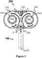
- Each volute contains a vortex finder 240 and 250 that forms an EYE within each vortex finder 240 and 250.
- RF torches using an RF coil or a Microwave source typically employ a susceptor to ignite the plasma.
- the susceptor is simply a pointed metal rod that will absorb the RF energy, heat up and then emit an electron via thermionic emission. As a result, the spark ignites any gases present and forms the plasma.
- FIGURE 7 a plasma arc torch 100 in accordance with one embodiment of the present invention is shown.
- the plasma arc torch 100 is a modified version of the ARCWHIRL® device disclosed in U.S. Patent Number 7,422,695 that produces unexpected results.
- plasma arc torch 100 includes a cylindrical vessel 104 having a first end 116 and a second end 118.
- a tangential inlet 120 is connected to or proximate to the first end 116 and a tangential outlet 102 (discharge volute) is connected to or proximate to the second end 118.
- An electrode housing 122 is connected to the first end 116 of the cylindrical vessel 104 such that a first electrode 112 is aligned with the longitudinal axis 124 of the cylindrical vessel 104, extends into the cylindrical vessel 104, and can be moved along the longitudinal axis 124.
- a linear actuator 114 is connected to the first electrode 112 to adjust the position of the first electrode 112 within the cylindrical vessel 104 along the longitudinal axis of the cylindrical vessel 124 as indicated by arrows 126.
- the hollow electrode nozzle 106 is connected to the second end 118 of the cylindrical vessel 104 such that the centerline of the hollow electrode nozzle 106 is aligned with the longitudinal axis 124 of the cylindrical vessel 104.
- the shape of the hollow portion 128 of the hollow electrode nozzle 106 can be cylindrical or conical.
- the hollow electrode nozzle 106 can extend to the second end 118 of the cylindrical vessel 104 or extend into the cylindrical vessel 104 as shown.
- the vortex 132 confines the plasma 108 within in the vessel 104 by the inertia (inertial confinement as opposed to magnetic confinement) caused by the angular momentum of the vortex, whirling, cyclonic or swirling flow of the gas (e.g., air), fluid (e.g., water) or steam 110 around the interior of the cylindrical vessel 104.
- the linear actuator 114 moves the first electrode 112 into contact with the hollow electrode nozzle 106 and then draws the first electrode 112 back to create an electrical arc which forms the plasma 108 that is discharged through the hollow electrode nozzle 106.
- the linear actuator 114 can adjust the position of the first electrode 112 to change the plasma 108 discharge or account for extended use of the first electrode 112.
- FIGURES 8 and 9 a different approach is used to achieve the same goal - treating material with multiple cyclones attached to a single gas vessel.
- the gas vessel allows for feeding multiple cyclones.
- the heater or heated gas source is an ArcWhirl Torch 100 that discharges its plasma into the vessel. Consequently, the plasma discharges into each cyclone.
- Each cyclone has attached to it the microwave or RF source. And of course material is fed into the EYE of the whirling plasma of each volute.
- each cyclone may be a twin volute cyclone which would be keeping in the various embodiments of the present invention.
- a heated gas is supplied to the inlet of the inlet passage in block 1204, and the heated gas is directed into the first cylindrical vessel to form a first vortex gas flow and the second cylindrical vessel to form a second vortex gas flow using the wedge or divider in block 1206.
- the matter is dropped into the first vortex finder or the second vortex finder or both the first vortex finder and the second vortex finder in block 1208 such that the matter is treated in a selected temperature range as the matter passes through a first central portion of the first vortex gas flow and exit the second end of the first cylindrical vessel and/or pass through a second central portion of the second vortex flow and exit the fourth end of the second cylindrical vessel.
- the present invention uses of multiple small diameter cyclones fed from a common header provides for a compact proppant manufacturing plant or system that is efficient and scalable. Likewise, this configuration enables the plant to increase production capacity via small increments and not through the purchase of one long rotary kiln or one large plasma process.
- the present invention allows the proppants to be manufactured in a multi-stage sintering process wherein addition materials can be added to, coated or reacted with the proppants to produce new and improved characteristics.
- the ability to use off-the-shelf and/or modified high temperature and high pressure cyclones sourced from the oil and gas industry as a component for a plasma proppant manufacturing system allows for a relatively compact, modular and inexpensive plant that could be built in a timely fashion.
- the present invention provides a system that can be mounted on a skid and operated at or near the drilling operation which greatly reduces the cost of the proppants by saving expensive storage and transportation costs.
- the plasma torch was aimed tangentially to an invisible EYE, the plasma did not affect the alumina ceramic because, it was protected by the form. Hence, the form acted as an ablative liner. Consequently, by feeding material counter current to the plasma, then the material becomes an ablative plug, thus protecting the twin ceramic cyclones.
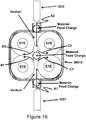
- FIGURE 16 is another embodiment of the present invention.
- the following example will held explain the novely and unobviousness of the present invention of FIGURE 16 .
- this configuration is known as locked train. If one gear is rotated then the opposing gear will rotate in the opposite direction.
- the hot gas A1 discharging from hot gas generator 1001 will flow in the direction as shown by arrows B1 and C1.
- the opposing cyclones will flow the hot gas A2 from hot gas generator 1002 as shown by arrows B2 and C2.
- a venturi will be formed by each of the cyclones, thus this gives rise to another novel and unobvious mode of operation.
- a material feed charge hole may be placed by the exit of plasma torch 1001 and plasma torch 1002.
- this allows for particle to particle collision of matter due to the high velocity of the plasma jet, consequently allowing for rapid treatment of the matter.
- material may be fed directly between the two opposing torches 1001 and 1002 that would be the center of device 20012. Once again, this would form an ablative plug between plasma torches 2001 and 2002, thus protecting the torches.
- plasma torch 1001 or 1002 may be a countercurrent feed tube in lieu of a hot gas generator.
- torch 100 of the '663 patent would be torch 100 of FIGURE 17 of the present invention.
- utilizing steam plasma allows for rapid conversion of petcoke to syngas consisting of hydrogen and carbon monoxide. The syngas is then scrubbed in the combined gas and water treatment unit.
- drill cuttings and frac flowback Two additional streams found within the upstream oil and gas industry that present major problems are drill cuttings and frac flowback.
- the US EPA has regulated flare gas from frac flowback and effective January 1, 2015, operators must beneficially use the natural gas within the frac flowback.
- the present invention allows for treating both frac flowback and drill cuttings simultaneously.
- drill cuttings would be the solid material fed from the hopper into the plasma torch 100 via the Tee.
- the drill cuttings would be partially melted on the fly then discharged into the center or eye of a venture scrubber in which the scrubbing media would be the frac flowback. Additional air would be added into the frac flowback.
- the extremely red hot drill cutting particles would act as the ignition source for combusting the natural gas and air.
- VOCs volatile organic compounds
- cement industry Another industry that has been recently regulated is the cement industry.
- VOCs volatile organic compounds
- the US EPA will regulate the discharge of emissions, in particular VOCs from cement production facilities.
- raw meal may be fed to any of the material feed charge ports and preheated with an oxygen or air plasma.
- the foregoing description of the present invention provides a method for treating matter. The high temperatures will destroy or combust the VOCs. Since the VOCs are at a low limit, then an air plasma with a low volume of air may be sufficient to fully thermally oxidize the organics.
- the abundance of shale gas and methane hydrates allows for rapid mobilization of the Systems, Methods and Apparatuses described herein.
- natural gas can be cracked into hydrogen and carbon by using it as the plasma gas within the torch 100.
- the twin volute cyclone 200 will separate the carbon from the hydrogen, thus producing a clean stream of hydrogen.
- the hydrogen can be further scrubbed with a combined gas and water treatment system as shown in FIGURE 16 .
- a heated gas is supplied to the inlet of the inlet passage, and the heated gas is directed into the first cylindrical vessel to form a first vortex gas flow and the second cylindrical vessel to form a second vortex gas flow using the wedge or divider.
- the matter is dropped into the first vortex finder or the second vortex finder or both the first vortex finder and the second vortex finder such that the matter is treated in a selected temperature range as the matter passes through a first central portion of the first vortex gas flow and exit the second end of the first cylindrical vessel and/or pass through a second central portion of the second vortex flow and exit the fourth end of the second cylindrical vessel.
- the present invention uses of multiple small diameter cyclones fed from a common header provides for a compact treating plant or system that is efficient and scalable. Likewise, this configuration enables the plant to increase treatment capacity via small increments and not through the purchase of one long rotarty kiln, upgrader, gasifier or one large plasma process.
- the present invention allows the matter to be manufactured in a multi-stage treating process wherein addition materials can be added to, coated or reacted with the matter to produce new and improved characteristics.
- the ability to use off-the-shelf and/or modified high temperature and high pressure cyclones sourced from the oil and gas industry as a component for a plasma treatment system allows for a relatively compact, modular and inexpensive plant that could be built in a timely fashion.
- the present invention provides a system that can be mounted on a skid and operated at or near the drilling operation which greatly reduces the cost of treating matter by saving expensive storage and transportation costs.
Landscapes
- Chemical & Material Sciences (AREA)
- Organic Chemistry (AREA)
- Chemical Kinetics & Catalysis (AREA)
- Engineering & Computer Science (AREA)
- Oil, Petroleum & Natural Gas (AREA)
- Life Sciences & Earth Sciences (AREA)
- General Chemical & Material Sciences (AREA)
- Materials Engineering (AREA)
- Ceramic Engineering (AREA)
- General Life Sciences & Earth Sciences (AREA)
- Wood Science & Technology (AREA)
- Combustion & Propulsion (AREA)
- Dispersion Chemistry (AREA)
- Structural Engineering (AREA)
- Physics & Mathematics (AREA)
- Fluid Mechanics (AREA)
- Physical Or Chemical Processes And Apparatus (AREA)
- Plasma Technology (AREA)
- Devices And Processes Conducted In The Presence Of Fluids And Solid Particles (AREA)
Description
- The present invention relates generally to the field of high temperature processing of matter with a multi-whirl cyclone reactor.
- The United States, as well as many other countries, has an abundant source of unconventional Oil and Gas resources located in shale formations and sand formations. Hence, the terms Shale Oil, Shale Gas and Oil Sands. However, these tight shale formations require a unique completion method, referred to as hydraulically fracturing, to untrap the oil and/or gas and allow it to flow to the production tubing of the well. Likewise, Oil Sands require a unique production method termed Steam Assisted Gravity Drainage ("SAGD") to get the bitumen to flow out of the formation using steam to decrease the viscosity.
- In addition, heavy oil production is increasing worldwide. The problem associated with oil sands and heavy oil is the viscosity of the bitumen and heavy oil. Consequently, one of the first processing steps is upgrading. Likewise, some producers gasify heavy oil to produce a gaseous mixture of hydrogen and carbon monoxide commonly referred to as syngas. Likewise, refineries processing heavy crude will often send the bottoms or residuals referred to as resid to a delayed coker. In all cases, whether upgrading, gasifying or coking the result leads to soot cake and coke. And coke is piling up at many oil sand upgrading facilities. Thus, there exists a need for converting coke and soot cake to higher valuable products such as calcined coke, syngas or hydrogen.
- Furthermore with the depressed prices of natural gas when compared and contrasted to crude oil, many natural gas wells are capped after drilling and completing the well. Consequently, the abundant supply of a very clean burning fuel, natural gas, competes with crude oil. Thus, there exists a need for converting natural gas to a higher value product, for example, hydrogen, syngas, carbon black or a liquid fuel. When converting natural gas to a liquid fuel the process is commonly referred to as Gas To Liquids and abbreviated GTL.
- The world has an abundant supply of coal. However, coal requires mining, crushing, grinding, water washing and drying prior to firing in a tangentially fired (Tee-Fired) boiler for production of steam which is used for generating electricity or for heating purposes.
- In addition, the world has an abundant supply of biomass. However, processing biomass for use as a fuel is similar to coal and often requires many steps such as harvesting, transporting, shredding, grinding, drying and pelletizing. There exists an immediate need for reducing the number of steps for either burning biomass or converting it to higher value materials such as biochar and syngas, in particular syngas with a high concentration of hydrogen.
- Likewise, many waste products such as food, garbage, oil and grease from restaurants is being hauled to biodiesel facilities. However, once again a low value byproduct residual remains from the conversion of oil, fats and greases to biodiesel via the transesterification process. The byproduct is glycerin. It is well known and well understood that glycerin has a high hydrogen content, thus makes an ideal feedstock for a gasifier for conversion to hydrogen.
- Returning back to drilling and completing oil and gas wells as well as production wells, many wastes are produced ranging from drill cuttings to frac flowback to produced water and to flare gas. The US EPA has coined a term "Green Completion" that is actually a regulation beginning in 2015, that requires natural gas to be put to good use in lieu of flaring or wasting the natural gas. Thus, there is an absolute immediate need for a simple process for using the natural gas during the completion process.
- Another industry outside of the energy industry that is in dire need of a high temperature solution is the cement industry. During the production of Portland cement Volatile Organic Compounds ("VOCs") are released when feed mill is fed into the preheater. Likewise, many cement kilns fire refuse derived fuel ("RDF"). A technology that could rapidly preheat feed mill while destroying or thermally oxidizing VOCs would help cement plants maintain current production capacities. Likewise, a technology that could flash sinter feed mill and produce a nano-clinker cement would dramatically change the cement industry.
- Although many other sources of fossil fuels, biomass, RDF, and minerals could be enumerated, in order to be brief the term "matter" and "particular matter" as used herein refers top particles, ions, atoms, molecules and elements in solid, liquid, gas or plasma states.
- The major issues associated with the manufacture of cement are cost, production capacity and emissions. The traditional method for treating cement uses long rotary kilns fired with coal, fuel oil, natural gas and RDF. First, the construction and installation of a new rotary kiln is expensive and requires a long lead-time (e.g., upwards of 18 to 24 months), so capacity expansion is difficult. Second, if the price of natural gas increases the production costs increase. Third, many facilities utilizing rotary kilns must install expensive scrubbers to reduce air emissions. Other issues associated with long rotary kilns are size, footprint, plant location and regulatory permits. The combination of these problems causes long lead times and thus hampers a company's ability to increase production capacity to keep up with demand of high performance cement.
- In addition, treating time within a rotary kiln is exceptionally long in order to reach a typical treating temperature of 2,800°F to 3,000°F. Typical treating times range from 30 minutes to over one hour. If temperature creeps beyond the treating temperature, the lower melting point metals and/or minerals within the feed mill tend to melt and "plate" out within the kiln. Thus, the rotary kiln must be shutdown, cooled and repaired and of course adversely affects the plants production capacity.
- Due to the abundance of natural gas and oil from shale plays, there exists a need for conversion of low value matter to higher value matter such as conversion of natural gas to hydrogen, conversion of coke to hydrogen, conversion of glycerin to hydrogen and conversion of biomass to various high value products such as syngas and biochar. In addition, there exists an immediate need for conversion of matter to syngas then syngas to liquid fuels hereinafter referred to as Syngas To Liquids ("STL"), whether the starting matter is derived from fossil fuels, biomass, agriculture waste, sewage and wastewater biosolids/biogas or glycerin.
- Although many other sources of fossil fuels, biomass, RDF, and minerals could be enumerated, in order to be brief the term "matter" and "particular matter" as used herein refers to particles, ions, atoms, molecules and elements in solid, liquid, gas or plasma states.
- Likewise, to be very concise but not all inclusive the remaining disclosure will refer to heating fluids, in particularly frac water, frac flowback, produced water in a submerged countercurrent twin vortex combustion mode for applications found within the oil and gas industry. On April 17, 2012, the U.S. Environmental Projection Agency (EPA) issued cost-effective regulation, required by the Clean Air Act, to reduce armful air pollution from the oil and natural gas industry while allowing continued, responsible growth in U.S. oil and natural gas production. The final rules include the first federal air standards for natural gas wells that are hydraulically fractured, along with requirements for several other sources of pollution in the oil and gas industry for which there are currently no federal standards. The present invention provides a means for oil and gas operators top meet the EPA's timeline with a simple system that uses the natural gas, oil and other organic within the water for heating the water.
US 2011/303532 A1 discloses a system for treating a substance using a storage vessel and two or more devices disposed in a top of the storage vessel, each device comprising a volute or cyclone head. - The present invention provides an apparatus for treating matter according to claim 1.
- In addition, the present invention provides a method for treating matter according to claim 2.
- The present invention is described in detail below with reference to the accompanying drawings.
- The above and further advantages of the invention may be better understood by referring to the following description in conjunction with the accompanying drawings, in which:
-
FIGURE 1 is a diagram of an apparatus for treating matter in accordance with one embodiment of the present invention; -
FIGURE 2 is a diagram of an apparatus for treating matter in accordance with another embodiment of the present invention; -
FIGURE 3 is a diagram of an apparatus for treating matter in accordance with another yet embodiment of the present invention; -
FIGURE 4 is a diagram of an apparatus for treating matter in accordance with another yet embodiment of the present invention; -
FIGURE 5 is a diagram of an apparatus for treating matter in accordance with another yet embodiment of the present invention; -
FIGURE 6 is a diagram of an apparatus for treating matter in accordance with another yet embodiment of the present invention; -
FIGURE 7 is a diagram of an apparatus for treating matter in accordance with another yet embodiment of the present invention; -
FIGURE 8 is a diagram of an apparatus for treating matter in accordance with another yet embodiment of the present invention. -
FIGURE 9 is a diagram of an apparatus for sintering proppants in accordance with another yet embodiment of the present invention; -
FIGURE 10 is a diagram of an apparatus for sintering proppants in accordance with another yet embodiment of the present invention; and -
FIGURE 11 is a diagram of an apparatus for sintering proppants in accordance with another yet embodiment of the present invention; and -
FIGURE 12 is a flow chart of a method for treating matter in accordance with one embodiment of the present invention; -
FIGURE 13 is a diagram of an apparatus for treating matter in accordance with another yet embodiment of the present invention; -
FIGURE 14 is a diagram of an apparatus for treating matter in accordance with another yet embodiment of the present invention; -
FIGURE 15 is a diagram of an apparatus for treating matter in accordance with another yet embodiment of the present invention; -
FIGURE 16 is a diagram of an apparatus for treating matter in accordance with another yet embodiment of the present invention; and -
FIGURE 17 is a process flow diagram of a system for treating matter in accordance with another yet embodiment of the present invention; - While the making and using of various embodiments of the present invention are discussed in detail below, it should be appreciated that the present invention provides many applicable inventive concepts that can be embodied in a wide variety of specific contexts. The specific embodiments discussed herein are merely illustrative of specific ways to make and use the invention and do not delimit the scope of the invention. The discussion herein relates primarily to heating fluids within the Oil and Gas Industry, but it will be understood that the concepts of the present invention are applicable to the manufacture or processing of particles at high temperatures.
- The present invention relates to a high temperature twin whirl cyclone reactor system, method and apparatus that can be operated in one or more modes selected from the following group; plasma arc cracker, arc pyrolysis reactor, gasifier, rapid arc furnace, flash treating reactor, steam plasma reformer, plasma thermal oxidizer, vortex burner, submerged combustor, atomic oxygen and ozone generator, fast quench reactor, Fischer-Tropsch Reactor, high temperature atomizer, high temperature communition reactor, steam super heater and separator, or as a lean or rich multi-whirl burner/combustor. Very specifically, the present invention relates to a high temperature twin whirl cyclone reactor for generating hydrogen from matter containing carbon. Likewise, the present invention relates to a high temperature twin whirl cyclone catalytic reactor for converting syngas to liquids commonly referred to as gas to liquids ("GTL"). In addition, the present invention relates to a Quad Whirl Cyclone Reactor for treating matter, in particular converting matter to hydrogen and/or higher value products. Furthermore, the present invention relates to a high temperature multi-cyclone reactor for pretreating cement kiln feed mill and flash treating cement. Very specifically, the present invention relates to a system, method and apparatus for heating water for fracturing oil and gas wells and for heating frac flowback water for green completion of hydraulically fractured oil and gas wells and for heating water and steam for enhanced oil recovery ("EOR") using a high temperature countercurrent vortex reactor.
-
FIGURES 1-12 show various embodiments of an apparatus for treating matter in accordance with the present invention. Note that the terms matter and material are used interchangeably throughout the description. Moreover the matter or material may include green pellets such that the present invention sinters the green pellets to make proppant particles. The basic apparatus in accordance with these embodiments includes: (a) a first cylindrical vessel having a first end, a second end and a first longitudinal axis; (b) a first vortex finder connected to the first end of the first cylindrical vessel and aligned with the first longitudinal axis; (c) a second cylindrical vessel having a third end, a fourth end and a second longitudinal axis; (d) a second vortex finder connected to the third end of the second cylindrical vessel and aligned with the second longitudinal axis; (e) an inlet passage disposed between the first vortex finder and the second vortex finder, connected tangentially to both the first cylindrical vessel proximate to the first end and the second cylindrical vessel proximate to the third end, and having an inlet and a third longitudinal axis; (f) a wedge or divider disposed within the inlet passage along the third longitudinal axis that directs a heated gas from the inlet into the first cylindrical vessel to form a first vortex gas flow and the second cylindrical vessel to form a second vortex gas flow; (g) a heater or heated gas source connected to the inlet of the inlet passage; and (h) a matter source connected to the first vortex finder or the second vortex finder or both the first vortex finder and the second vortex finder such that the matter drops into the first vortex finder or the second vortex finder or both the first vortex finder and the second vortex finder and is treated or partially treated in a selected temperature range to form inert particles as the matter passes through a first central portion of the first vortex gas flow and exit the second end of the first cylindrical vessel and/or pass through a second central portion of the second vortex flow and exit the fourth end of the second cylindrical vessel. - As will be explained in more detail below, a material can be added to the first vortex gas flow or the second vortex gas flow that coats or chemically reacts with the matter. Moreover, the matter can be partially treated in the first cylindrical vessel and fully fired or treated in the second cylindrical vessel. The selected temperature range is between about 1,200°C and 3,700°C. In addition, the selected temperature range is typically based on a chemical composition of the matter, particle size of the matter, a resonance time of the matter within the first cylindrical vessel, the second cylindrical vessel or both. Note that other parameters may also be used to determine the selected temperature range.
- The wedge or divider can be fixed, pivotable such that first vortex gas flow is different from the second vortex gas flow, and/or moveable along the third longitudinal axis. Moreover, the wedge or divider can be an electrode or a counter current feed tube containing a material that coats or chemically reacts with the matter (
FIGURE 7 ). As shown inFIGURES 4 and5 , the first cylindrical vessel and the second cylindrical vessel can be cylinder-shaped or cone-shaped. Note that both cylindrical vessels can be the same shape. - Now referring to
FIGURE 1 , a heater orheated gas source 100 is attached along alongitudinal axis 124 to atwin volute cyclone 200. Thetwin volute cyclone 200 consists of anentry nozzle 230 to direct a hot gas A from the heater orheated gas source 100 into thetwin volute cyclone 200 and is divided by means of a wedge ordivider 201. The wedge ordivider 201 divides the hot gas A into a firstvolute annulus space 210 and its mirror image secondvolute annulus space 220. The wedge ordivider 201 may be attached to a pivot, thus allowing for the wedge or divider to act as a gate valve for directing more or less gas into either side of the twin volutes. The gas rotates in the firstvolute annulus space 210 as shown by arrow B and the second volute annulus space as shown by arrow C. Each volute contains avortex finder vortex finder - Matter that is hard and needs to be crushed, shredded and/or comminuted can be fed into and near hot gas A. On the other hand, the EYE moves at a very low speed and is, therefore, an ideal Feed Point for delicate materials that do not need to be comminuted by just need to be heated to a firing temperature. This allows for rapid treating of either hard of delicate matter (i.e., seconds as opposed to 30 minutes or more in long rotary kilns).
- The heater or
heated gas source 100 may be selected but is not limited to a group that includes a high temperature blower or compressor, electrical heater or heated gas source, burner, thermal oxidizer, gasifier, reformer, jet rocket, oxy-fuel torch, plasma torch and/or even the exhaust from an internal combustion engine such as a reciprocating engine or gas turbine engine. The utilization of engine exhaust allows for generating electricity while treating matter. Hence, a unique cogenerating system - generating electricity while treating matter. In another example, the heater or heated gas source includes a first electrode proximate to inlet of the inlet passageway and aligned with the third longitudinal axis, and the wedge or divider is a second electrode. - Turning now
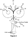
FIGURE 2 , the heater orheated gas source 100 can be the DC Plasma ArcWhirl® Torch disclosed inUS Patent Numbers 8,074,439 and8,278,810 and7,622,693 and8,324,523 . Likewise, an ideal heater or heated gas source may be the thermal oxidizer shown inFigure 6 of the '439 patent or the plasma rocket as disclosed inFigure 7 of the '439 patent. - The heater or heated gas source includes: (a) a third cylindrical vessel having a fifth end, a sixth end and a fourth longitudinal axis; (b) a tangential inlet connected to or proximate to the fifth end; (c) a tangential outlet connected to or proximate to the sixth end; (d) an electrode housing connected to the sixth end of the third cylindrical vessel such that a first electrode is aligned with the fourth longitudinal axis of the third cylindrical vessel, extends into the third cylindrical vessel, and can be moved along the fourth longitudinal axis; (e) a linear actuator connected to the first electrode to adjust a position of the first electrode within the third cylindrical vessel along the fourth longitudinal axis of the cylindrical vessel; and (f) a hollow electrode nozzle connected to the sixth end of the third cylindrical vessel such that a center line of the hollow electrode nozzle is aligned with the fourth longitudinal axis of the fourth cylindrical vessel. The tangential inlet and the tangential outlet create a third vortex flow within the third cylindrical vessel, and the first electrode and the hollow electrode nozzle create a plasma that discharges through the hollow electrode nozzle and into the inlet of the inlet passageway.
- Referring to both
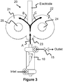
FIGURE 1 andFIGURE 3 of the present invention an Electrode may be used as the wedge ordivider 201 in order to transfer the arc from the DC PlasmaArcWhirl® torch 100. Likewise, continually feeding the electrode allows for continuous operation. In addition, by using graphite electrodes this adds fuel to the fire but more importantly allows for production of hydrogen via the steam reforming reaction of steam and carbon. It will be understood that any electrically conductive material may be used for the electrode. For example, copper is an ideal electrode for plasma systems since it has a high electrical conductivity as well as thermal conductivity. Consequently, by cooling the copper electrode this allows for extended operation. - The present invention can also use an electrode material that can be coated unto the matter. For example, titanium is a lightweight electrically conductive metal that is available in rods, bars or tubes which can be fed continuously for coating the matter with a high strength lightweight metal. On the otherhand, tungsten is a heavy electrically conductive metal that may be used to coat matter.
- Turning now to
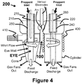
FIGURE 1 andFIGURE 4 , the present invention will be described in another embodiment.FIGURE 4 discloses a twin volute with one volute attached to a cone and the other attached to a cylinder. It will be understood that the volutes may be attached to cones or to cylinders or any other shape for practicing the present invention. The cone and cylinder attached to the twin volute is for illustrative purposes only and is not limited in scope to the present invention. - Likewise, the twin volute plasma torch is a dual inductively coupled plasma torch utilizing radio frequency in the range of 0.5 kHz to 300 MHz. A
microwave source 410 and/or aninduction coil 400 may be attached to or disposed within either the cone or cylinder in order to couple to the plasma generated by the plasma arc heater orheated gas source 100. The vertical configuration allows for a simple carbonarc electrode configuration 100 disposed in a vertical fashion. For example, the first electrode is proximate to the inlet of the inlet passageway and aligned in a plane substantially perpendicular to the third longitudinal axis, and the third electrode is aligned longitudinally with the first electrode such that an electrical arc between the first and second electrodes intersects the third longitudinal axis. This allows for continuously feeding both carbon electrodes. - The carbon plasma arc may provide the excitation energy for either the microwaves or RF energy to couple to and form a global plasma within the EYE. However,
susceptors vortex finders - In order to treat matter that is fragile, the matter is charged into the
vortex finders - Plasma can couple to Radio Frequency Energy (e.g., inductively coupled ("IC") plasma torches, etc.). The present inventor's Plasma Whirl® Reactor is an IC Plasma Torch. The Radio Frequency ("RF") Spectrum ranges from about 3 kHz to 300 GHz. Induction heating commonly employs RF coils ranging in frequency from 0.5 kHz to 400 kHz. Likewise, microwave frequencies commonly found in household microwave ovens normally operate at 2,450 Mega Hertz (2.450 GigaHertz) and at a power of 300 watts to 1,000 watts. Commercial microwave ovens ranging in power from 6 kw to 100 kw typically operate at a frequency of 915 MHz (Mega Hertz).
- As previously stated RF energy can couple to a gas and form plasma. Coupling efficiency is based upon several variables ranging from the gas type, gas flow rate, frequency, cavity and/or reactor shape and volume. Note that the radio frequency source can be one or more radio frequency coils, a waveguide, or a combination thereof.
- The three major issues with plasma are igniting, sustaining and confining the plasma. Igniting and sustaining plasma with an electrical arc is fairly straightforward and simple. DC plasma torches utilize inertial confinement to maximize and transfer energy to the work piece. Likewise, plasma confinement is necessary to prevent melting of the torch itself.
- However, plasma ignition with RF energy is quite difficult. Consequently, many RF torches using an RF coil or a Microwave source typically employ a susceptor to ignite the plasma. The susceptor is simply a pointed metal rod that will absorb the RF energy, heat up and then emit an electron via thermionic emission. As a result, the spark ignites any gases present and forms the plasma.
- Turning back to
FIGURE 4 , asusceptor vortex finder heated gas source 100 allows for increasing the bulk plasma volume by simply turning on the RF coil or Microwave generator and injecting WAVE ENERGY in the form of photons emitted from the RF coil or the Microwave magnetron to enhance the plasma. - Turning now to
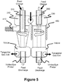
FIGURE 5 , a second volute may be attached to the cylinder and/or cone of the top volutes. Although the bottom volutes each disclose a tangential exit, it will be understood that a twin volute may be flipped upside down and used on the bottom thus having a single exit. This configuration is commonly referred to as a through-flow hydrocyclone. Thus, the feed charge tubes are axially and vertically aligned with the vortex/eye finder of the bottom volutes. This allows for green matter to fall straight through the high temperature inductively coupled plasma eye and exit the feed discharge as fully treated matter. - For example, a third vortex finder can be connected to the second end of the first cylindrical vessel and aligned with the first longitudinal axis, and a first tangential outlet connected to or disposed proximate to the second end of the first cylindrical vessel such that the first vortex gas flow exits the first cylindrical vessel through the first tangential outlet. Likewise, a fourth vortex finder can be connected to the fourth end of the second cylindrical vessel and aligned with the second longitudinal axis, and a second tangential outlet connected to or disposed proximate to the fourth end of the second cylindrical vessel such that the second vortex gas flow exits the second cylindrical vessel through the second tangential outlet. Alternatively, the two tangential outlets can be combined into an outlet passage disposed between the first vortex finder and the second vortex finder, connected tangentially to both the first cylindrical vessel proximate to second first end and the second cylindrical vessel proximate to the fourth end, and having an outlet.
- Turning now to
FIGURE 6 a counter current feed tube is aligned along thelongitudinal axis 124 with the PlasmaArcWhirl® Torch 100. Plasma spraying and coating of materials is well known and well understood. A material may be fed into the counter current feed tube in order to coat the matter and/or chemically react with the matter. For example, titanium or titanium dioxide may be fed in order to coat the matter with a nano-coating of titanium. Although not shown, material may be conveyed into the counter current feed tube via a pump, screw feeder, auger, progressive cavity pump, pneumatic conveyor or any other conveyance means known in the art for moving solids, liquids and gases. An ideal conveyance means for recovering fluids coating matter, for example recovering drilling fluids from drill cuttings is utilizing a screw press, then pulling a vacuum on the screen in order to induce some of the plasma into the feed tube, while still moving the solids into the plasma. This configuration would allow for counter current heating of the solids to remove valuable drilling fluids. Likewise, this configuration allows for preheating material prior to entry into the bulk plasma. Petroleum coke, soot cake from gasifiers and coal are ideal examples of wet material that may be preheated prior to injection into the plasma through the counter current feed tube. - Although previously disclosed in the present inventor's patents, the
ArcWhirl® Torch 100 will be briefly described to demonstrate the novelty and unobvious operation of attaching it to atwin volute 200. Referring toFIGURE 7 , aplasma arc torch 100 in accordance with one embodiment of the present invention is shown. Theplasma arc torch 100 is a modified version of the ARCWHIRL® device disclosed inU.S. Patent Number 7,422,695 that produces unexpected results. - More specifically, by attaching a
discharge volute 102 to the bottom of thevessel 104, closing off the vortex finder, replacing the bottom electrode with ahollow electrode nozzle 106, an electrical arc can be maintained while dischargingplasma 108 through thehollow electrode nozzle 106 regardless of how much gas (e.g., air, nitrogen, helium, hydrogen), fluid (e.g., water) orsteam 110 is injected intoplasma arc torch 100. In addition, when a throttle valve is connected to thedischarge volute 102, the mass flow ofplasma 108 discharged from thehollow electrode nozzle 106 can be controlled by throttling the throttle valve while adjusting the position of thefirst electrode 112 using thelinear actuator 114. - As a result,
plasma arc torch 100 includes acylindrical vessel 104 having afirst end 116 and asecond end 118. Atangential inlet 120 is connected to or proximate to thefirst end 116 and a tangential outlet 102 (discharge volute) is connected to or proximate to thesecond end 118. An electrode housing 122 is connected to thefirst end 116 of thecylindrical vessel 104 such that afirst electrode 112 is aligned with thelongitudinal axis 124 of thecylindrical vessel 104, extends into thecylindrical vessel 104, and can be moved along thelongitudinal axis 124. Moreover, alinear actuator 114 is connected to thefirst electrode 112 to adjust the position of thefirst electrode 112 within thecylindrical vessel 104 along the longitudinal axis of thecylindrical vessel 124 as indicated byarrows 126. Thehollow electrode nozzle 106 is connected to thesecond end 118 of thecylindrical vessel 104 such that the centerline of thehollow electrode nozzle 106 is aligned with thelongitudinal axis 124 of thecylindrical vessel 104. The shape of thehollow portion 128 of thehollow electrode nozzle 106 can be cylindrical or conical. Moreover, thehollow electrode nozzle 106 can extend to thesecond end 118 of thecylindrical vessel 104 or extend into thecylindrical vessel 104 as shown. As shown inFIGURE 7 , thetangential inlet 120 is a volute attached to thefirst end 116 of thecylindrical vessel 104, thetangential outlet 102 is a volute attached to thesecond end 118 of thecylindrical vessel 104, the electrode housing 122 is connected to theinlet volute 120, and the hollow electrode nozzle 106 (cylindrical configuration) is connected to thedischarge volute 102. Note that theplasma arc torch 100 is not shown to scale. - A
power supply 130 is electrically connected to theplasma arc torch 100 such that thefirst electrode 112 serves as the cathode and thehollow electrode nozzle 106 serves as the anode. The voltage, power and type of thepower supply 130 is dependent upon the size, configuration and function of theplasma arc torch 100. A gas (e.g., air), fluid (e.g., water) orsteam 110 is introduced into thetangential inlet 120 to form a vortex 132 within thecylindrical vessel 104 and exit through thetangential outlet 102 asdischarge 134. The vortex 132 confines theplasma 108 within in thevessel 104 by the inertia (inertial confinement as opposed to magnetic confinement) caused by the angular momentum of the vortex, whirling, cyclonic or swirling flow of the gas (e.g., air), fluid (e.g., water) orsteam 110 around the interior of thecylindrical vessel 104. During startup, thelinear actuator 114 moves thefirst electrode 112 into contact with thehollow electrode nozzle 106 and then draws thefirst electrode 112 back to create an electrical arc which forms theplasma 108 that is discharged through thehollow electrode nozzle 106. During operation, thelinear actuator 114 can adjust the position of thefirst electrode 112 to change theplasma 108 discharge or account for extended use of thefirst electrode 112. - Referring to
FIGURES 1 ,3 and6 jointly, what is unique and unobvious to the present invention is that the arc may be blown out of thenozzle 106 and attached to the twin volute's 200nozzle 230. Likewise, the arc may be farther transferred along thelongitudinal axis 124 and attached and centered to the electrically conductive wedge ordivider 201 or the electrode as shown inFIGURE 3 . This configuration allows for continuous use. Furthermore, the countercurrent feed tube ofFIGURE 6 may be electrically conductive. Likewise, although not shown a wire, stinger or electrode may be fed down the center of the countercurrent feed tube. - In previous testing of the countercurrent feed configuration carbonaceous matter was fully converted to char and then to syngas when the
ArcWhirl® Torch 100 used steam as the plasma gas. Consequently, this configuration allows for the production of syngas while treating matter. This GREEN approach for treating matter allows for the production of a fuel during the treating method. - Not being bound by theory, matter that may contain alumina and iron, together form a very common catalyst used for making liquid fuels from gases. This process and catalyst is referred to as Fischer Tropschs and is commonly referred to as Gas To Liquids ("GTL") when the starting fossil fuel is natural gas. Thus, in lieu of burning natural gas in a large rotary furnace, the present invention opens the door for a unique GTL process while treating matter. The FT reaction is an exothermic reaction. Consequently, this will aid in rapid treating of the matter and will help reduce the electrical load due to the
plasma torch 100. - Turning now to
FIGURE 7 while referring toFIGURE 1 , the present invention twin volute plasma system may be configured similar to a chain. This configuration allows for threetorches 100 to provide dual entries into two volutes. Thus, this stabilizes the EYE of the two center volutes. In addition, this allows for multiple passes of the proppants, for example a first pass and second pass, thus reducing the overall size and height of the system. - Turning now to
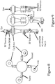
FIGURES 8 and 9 , a different approach is used to achieve the same goal - treating material with multiple cyclones attached to a single gas vessel. The gas vessel allows for feeding multiple cyclones. Once again, the heater or heated gas source is anArcWhirl Torch 100 that discharges its plasma into the vessel. Consequently, the plasma discharges into each cyclone. Each cyclone has attached to it the microwave or RF source. And of course material is fed into the EYE of the whirling plasma of each volute. Although not shown, it will be understood that each cyclone may be a twin volute cyclone which would be keeping in the various embodiments of the present invention. - Turning now to
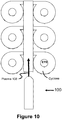
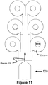
FIGURES 10 and11 theArcWhirl Torch 100 may be attached to a header or conduit that feeds multiple Plasma Volutes. Although not shown the volutes may be twin volutes. Once again proppants are fed directly into the EYE of the Plasma Whirl®. - As illustrated by
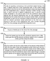
FIGURES 1-12 and the foregoing description, the present invention provides amethod 1200 for treating matter. A basic apparatus is provided inblock 1202 that includes: (a) a first cylindrical vessel having a first end, a second end and a first longitudinal axis; (b) a first vortex finder connected to the first end of the first cylindrical vessel and aligned with the first longitudinal axis; (c) a second cylindrical vessel having a third end, a fourth end and a second longitudinal axis; (d) a second vortex finder connected to the third end of the second cylindrical vessel and aligned with the second longitudinal axis; (e) an inlet passage disposed between the first vortex finder and the second vortex finder, connected tangentially to both the first cylindrical vessel proximate to the first end and the second cylindrical vessel proximate to the third end, and having an inlet and a third longitudinal axis; and (f) a wedge or divider disposed within the inlet passage along the third longitudinal axis. A heated gas is supplied to the inlet of the inlet passage inblock 1204, and the heated gas is directed into the first cylindrical vessel to form a first vortex gas flow and the second cylindrical vessel to form a second vortex gas flow using the wedge or divider inblock 1206. The matter is dropped into the first vortex finder or the second vortex finder or both the first vortex finder and the second vortex finder inblock 1208 such that the matter is treated in a selected temperature range as the matter passes through a first central portion of the first vortex gas flow and exit the second end of the first cylindrical vessel and/or pass through a second central portion of the second vortex flow and exit the fourth end of the second cylindrical vessel. - The present invention's use of multiple small diameter cyclones fed from a common header provides for a compact proppant manufacturing plant or system that is efficient and scalable. Likewise, this configuration enables the plant to increase production capacity via small increments and not through the purchase of one long rotary kiln or one large plasma process. The present invention allows the proppants to be manufactured in a multi-stage sintering process wherein addition materials can be added to, coated or reacted with the proppants to produce new and improved characteristics. Moreover, the ability to use off-the-shelf and/or modified high temperature and high pressure cyclones sourced from the oil and gas industry as a component for a plasma proppant manufacturing system allows for a relatively compact, modular and inexpensive plant that could be built in a timely fashion. Finally, the present invention provides a system that can be mounted on a skid and operated at or near the drilling operation which greatly reduces the cost of the proppants by saving expensive storage and transportation costs.
- Turning now to
FIGURE 13 while referring toFIGURE 1 , the present invention twin volute plasma system may be configured to be placed on top (shown) or bottom (not shown) of a twin volute cyclone. This configuration allows for using the twin cone to quench any reactions formed during the treating of matter. Likewise, this configuration also allows for using the twin cone as a combustor, thus thermally oxidizing any gases formed during the treating matter step. - Turning now to
FIGURE 14 , the Twin Whirl Apparatus may be constructed by placing off the shelf cyclone separators within a housing and then using a card board cyclinder to form a through bore as shown inFIGURE 15 . As previously disclosed this allows for feeding material counter current to the plasma. During testing of the present inventor's 4 torch PlasmaWhirl® Reactor, a QUIK-TUBE™ rigid fiber building form was used to form the hole or cavity within cyclone. Next, the form was removed by simply igniting a plasma torch. What happened next led to completely unexpected results. The QUIK-TUBE™ rigid fiber building form became an ablative liner. Although the plasma torch was aimed tangentially to an invisible EYE, the plasma did not affect the alumina ceramic because, it was protected by the form. Hence, the form acted as an ablative liner. Consequently, by feeding material counter current to the plasma, then the material becomes an ablative plug, thus protecting the twin ceramic cyclones. -
FIGURE 16 is another embodiment of the present invention. The following example will held explain the novely and unobviousness of the present invention ofFIGURE 16 . If four gears are placed touching one another similar to the four cyclones, then this configuration is known as locked train. If one gear is rotated then the opposing gear will rotate in the opposite direction. For example, the hot gas A1 discharging fromhot gas generator 1001 will flow in the direction as shown by arrows B1 and C1. On the other hand, the opposing cyclones will flow the hot gas A2 fromhot gas generator 1002 as shown by arrows B2 and C2. A venturi will be formed by each of the cyclones, thus this gives rise to another novel and unobvious mode of operation. A material feed charge hole may be placed by the exit ofplasma torch 1001 andplasma torch 1002. Thus, this allows for particle to particle collision of matter due to the high velocity of the plasma jet, consequently allowing for rapid treatment of the matter. On the other hand, material may be fed directly between the two opposingtorches device 20012. Once again, this would form an ablative plug between plasma torches 2001 and 2002, thus protecting the torches. It will be understood that eitherplasma torch - As illustrated by
FIGURE 16 a system, method and apparatus is shown for treating matter with the present invention. The system and method includes but is not limited to a material hopper with a rotary auger valve motor. The rotary auger valve motor may be controlled with a variable frequency drive ("VFD") thus allowing for precise feeding to the TEE. Thehot gas generator 100 fires its hot gas into the Multiple Cyclone Plasma Whirl® Reactor while educting the material into its high velocity hot gas stream. The hot gases and matter rise inside thetwin volute cyclone 200 orquad volute cyclone 20012. The matter and hot gases are discharged from thetwin volute cyclone 200 orquad volute cyclone 20012 and into a combined gas water treatment unit selected from the group consisting of an induced gas flotation cell ("IGF"), dissolved air flotation ("DAF") unit, Jameson Cell, froth flotation cell, venturi scrubber or any means for coupling gas scrubbing and water treating within one unit. - The following examples will demonstrate the novelty and unobviousness of the present invention when applied to real world problems. As previously stated as the world runs out of easy oil and gas, more oil and gas companies are going after unconventional oil and gas resources. Consequently, heavy oil must be upgraded or gasified which in turn produces petroleum coke and filter soot cake. Although many refineries view these streams as waste byproducts in particularly petcoke from oil sands upgraders, the pet coke can be utilized as a unique catalyst in the present invention. Referring to
FIGURE 6 of the present inventor's US Patent #8,568,663 titled "Solid Oxide High Temperature Electrolysis Glow Discharge Cell and Plasma System," that issued on October 29, 2013 the cyclone separator 610 would be the twin volute cyclone ofFIGURE 17 of the present invention. Likewise, torch 100 of the '663 patent would be torch 100 ofFIGURE 17 of the present invention. Thus, utilizing steam plasma allows for rapid conversion of petcoke to syngas consisting of hydrogen and carbon monoxide. The syngas is then scrubbed in the combined gas and water treatment unit. - Two additional streams found within the upstream oil and gas industry that present major problems are drill cuttings and frac flowback. The US EPA has regulated flare gas from frac flowback and effective January 1, 2015, operators must beneficially use the natural gas within the frac flowback. The present invention allows for treating both frac flowback and drill cuttings simultaneously. Referring to
FIGURE 17 drill cuttings would be the solid material fed from the hopper into theplasma torch 100 via the Tee. The drill cuttings would be partially melted on the fly then discharged into the center or eye of a venture scrubber in which the scrubbing media would be the frac flowback. Additional air would be added into the frac flowback. The extremely red hot drill cutting particles would act as the ignition source for combusting the natural gas and air. The mixture of combustion gases and quenched sintered drill cuttings would then flow to a frac tank. A vacuum would be pulled on the frac tank and the exhaust of noncondensible gases and water vapor would be vapor compressed and used to preheat the incoming frac flowback. Thus, this would produce distilled water for use as frac water in the next well to be drilled by the operator. - An additional benefit would be the volume reduction by melting the drill cuttings. The inventor of the present invention has demonstrated a 90% volume reduction when melting shale drill cuttings. Consequently, this allows for a dramatic reduction in hauling and disposal costs, especially when cuttings are injected downhole into a disposal well.
- If the operator desires to recover base fluid, then a screw press may be used to flow drill cuttings counter current to the plasma. This allows for recovering base fluid while melting drill cuttings.
- Another industry that has been recently regulated is the cement industry. When raw feed meal is preheated volatile organic compounds ("VOCs") within the raw meal vaporize and then are discharged into the atmosphere. Beginning in 2015, the US EPA will regulate the discharge of emissions, in particular VOCs from cement production facilities. Returning to
FIGURE 16 , raw meal may be fed to any of the material feed charge ports and preheated with an oxygen or air plasma. The foregoing description of the present invention provides a method for treating matter. The high temperatures will destroy or combust the VOCs. Since the VOCs are at a low limit, then an air plasma with a low volume of air may be sufficient to fully thermally oxidize the organics. - Another industry that is in dire need of a solution is the renewable energy industry in particularly the biodiesel industry. During the production of biodiesel via transesterfication, a waste byproduct, glycerin is produced in vast quantities. It is well known and well understood that glycerin is a highly rich hydrogen source. Referring to
FIGURE 17 , the glycerin is the feed material within the material hopper and is plasma steam reformed with theArcWhirl® torch 100, thus converting the glycerin to syngas. The syngas is scrubbed in the combined gas and water treatment unit. - The hydrogen economy is coming and the industry is in need of a small hydrogen generator. Referring to
FIGURES 1 through 17 , the abundance of shale gas and methane hydrates allows for rapid mobilization of the Systems, Methods and Apparatuses described herein. For example, natural gas can be cracked into hydrogen and carbon by using it as the plasma gas within thetorch 100. Thetwin volute cyclone 200 will separate the carbon from the hydrogen, thus producing a clean stream of hydrogen. The hydrogen can be further scrubbed with a combined gas and water treatment system as shown inFIGURE 16 . - The foregoing description of the basic apparatus is provided that includes: (a) a first cylindrical vessel having a first end, a second end and a first longitudinal axis; (b) a first vortex finder connected to the first end of the first cylindrical vessel and aligned with the first longitudinal axis; (c) a second cylindrical vessel having a third end, a fourth end and a second longitudinal axis; (d) a second vortex finder connected to the third end of the second cylindrical vessel and aligned with the second longitudinal axis; (e) an inlet passage disposed between the first vortex finder and the second vortex finder, connected tangentially to both the first cylindrical vessel proximate to the first end and the second cylindrical vessel proximate to the third end, and having an inlet and a third longitudinal axis; and (f) a wedge or divider disposed within the inlet passage along the third longitudinal axis. A heated gas is supplied to the inlet of the inlet passage, and the heated gas is directed into the first cylindrical vessel to form a first vortex gas flow and the second cylindrical vessel to form a second vortex gas flow using the wedge or divider. The matter is dropped into the first vortex finder or the second vortex finder or both the first vortex finder and the second vortex finder such that the matter is treated in a selected temperature range as the matter passes through a first central portion of the first vortex gas flow and exit the second end of the first cylindrical vessel and/or pass through a second central portion of the second vortex flow and exit the fourth end of the second cylindrical vessel.
- The present invention's use of multiple small diameter cyclones fed from a common header provides for a compact treating plant or system that is efficient and scalable. Likewise, this configuration enables the plant to increase treatment capacity via small increments and not through the purchase of one long rotarty kiln, upgrader, gasifier or one large plasma process. The present invention allows the matter to be manufactured in a multi-stage treating process wherein addition materials can be added to, coated or reacted with the matter to produce new and improved characteristics. Moreover, the ability to use off-the-shelf and/or modified high temperature and high pressure cyclones sourced from the oil and gas industry as a component for a plasma treatment system allows for a relatively compact, modular and inexpensive plant that could be built in a timely fashion. Finally, the present invention provides a system that can be mounted on a skid and operated at or near the drilling operation which greatly reduces the cost of treating matter by saving expensive storage and transportation costs.
Claims (20)
- An apparatus for treating matter comprising:a first cylindrical vessel having a first end, a second end and a first longitudinal axis;a first vortex finder connected to the first end of the first cylindrical vessel and aligned with the first longitudinal axis;a second cylindrical vessel having a third end, a fourth end and a second longitudinal axis;a second vortex finder connected to the third end of the second cylindrical vessel and aligned with the second longitudinal axis;an inlet passage disposed between the first vortex finder and the second vortex finder, connected tangentially to both the first cylindrical vessel proximate to the first end and the second cylindrical vessel proximate to the third end, and having an inlet and a third longitudinal axis;a divider disposed within the inlet passage along the third longitudinal axis that directs a heated gas from the inlet into the first cylindrical vessel to form a first vortex gas flow and the second cylindrical vessel to form a second vortex gas flow;a heated gas source connected to the inlet of the inlet passage; anda matter source connected to the first vortex finder or the second vortex finder or both the first vortex finder and the second vortex finder such that the matter drops into the first vortex finder or the second vortex finder or both the first vortex finder and the second vortex finder and is treated in a selected temperature range as the matter passes through a first central portion of the first vortex gas flow and exit the second end of the first cylindrical vessel and/or pass through a second central portion of the second vortex flow and exit the fourth end of the second cylindrical vessel.
- A method for treating matter comprising the steps of:providing an apparatus comprising:a first cylindrical vessel having a first end, a second end and a first longitudinal axis,a first vortex finder connected to the first end of the first cylindrical vessel and aligned with the first longitudinal axis,a second cylindrical vessel having a third end, a fourth end and a second longitudinal axis,a second vortex finder connected to the third end of the second cylindrical vessel and aligned with the second longitudinal axis,an inlet passage disposed between the first vortex finder and the second vortex finder, connected tangentially to both the first cylindrical vessel proximate to the first end and the second cylindrical vessel proximate to the third end, and having an inlet and a third longitudinal axis, anda divider disposed within the inlet passage along the third longitudinal axis;supplying a heated gas from a heated gas source to the inlet of the inlet passage;directing the heated gas into the first cylindrical vessel to form a first vortex gas flow and the second cylindrical vessel to form a second vortex gas flow using the divider; anddropping the matter into the first vortex finder or the second vortex finder or both the first vortex finder and the second vortex finder such that the matter is treated in a selected temperature range as the matter pass through a first central portion of the first vortex gas flow and exit the second end of the first cylindrical vessel and/or pass through a second central portion of the second vortex flow and exit the fourth end of the second cylindrical vessel.
- The apparatus or method as recited in claims 1 or 2, wherein a material is added to the first vortex gas flow or the second vortex gas flow that coats or chemically reacts with the matter.
- The apparatus as recited in claim 1, wherein the divider is movable along the third longitudinal axis or pivotable such that first vortex gas flow is different from the second vortex gas flow.
- The method as recited in claim 2, wherein the first vortex gas flow and the second vortex gas flow are adjusted by moving the divider along the third longitudinal axis or pivoting the divider.
- The method as recited in claim 2, wherein the matter is partially sintered in the first cylindrical vessel and sintered in the second cylindrical vessel.
- The apparatus or method as recited in claims 1 or 2, wherein the heated gas source comprises a high temperature blower, a high temperature compressor, an electrical heater or heated gas source, a burner, a thermal oxidizer, a jet exhaust, an oxy-fuel torch, a plasma torch, an internal combustion engine exhaust, or a combination thereof.
- The apparatus or method as recited in claims 1 or 2, wherein the first cylindrical vessel and the second cylindrical vessel are cylinder-shaped or cone-shaped.
- The method as recited in claim 2, wherein the selected temperature range is between 1,200°C and 3,700°C.
- The method as recited in claim 2, wherein the selected temperature range is based on a chemical composition of the matter, a size of the matter, a resonance time of the matter within the first cylindrical vessel, the second cylindrical vessel or both.
- The apparatus or method as recited in claims 1 or 2, wherein the heated gas source comprises:a third cylindrical vessel having a fifth end, a sixth end and a fourth longitudinal axis;a tangential inlet connected to or proximate to the fifth end;a tangential outlet connected to or proximate to the sixth end;an electrode housing connected to the sixth end of the third cylindrical vessel such that a first electrode is aligned with the fourth longitudinal axis of the third cylindrical vessel, extends into the third cylindrical vessel, and can be moved along the fourth longitudinal axis;a linear actuator connected to the first electrode to adjust a position of the first electrode within the third cylindrical vessel along the fourth longitudinal axis of the cylindrical vessel;a hollow electrode nozzle connected to the sixth end of the third cylindrical vessel such that a center line of the hollow electrode nozzle is aligned with the fourth longitudinal axis of the fourth cylindrical vessel; andwherein the tangential inlet and the tangential outlet create a third vortex flow within the third cylindrical vessel, and the first electrode and the hollow electrode nozzle create a plasma that discharges through the hollow electrode nozzle and into the inlet of the inlet passageway.
- The apparatus or method as recited in claim 11, wherein the divider comprises a second electrode.
- The apparatus or method as recited in claim 12, wherein the divider comprises a counter current feed tube containing a material that coats or chemically reacts with the matter.
- The apparatus or method as recited in claims 1 or 2, wherein the heated gas source comprises:a first electrode proximate to inlet of the inlet passageway and aligned with the third longitudinal axis;the divider comprises a second electrode; anda power source connected to the first electrode and the second electrode.
- The apparatus or method as recited in claim 14, wherein the first electrode or the second electrode contains a material that coats or chemically reacts with the matter.
- The apparatus or method as recited in claims 1 or 2, wherein the heated gas source comprises:a first electrode proximate to the inlet of the inlet passageway and aligned in a plane substantially perpendicular to the third longitudinal axis; anda third electrode aligned longitudinally with the first electrode such that an electrical arc between the first and second electrodes intersects the third longitudinal axis.
- The apparatus or method as recited in claims 1 or 2, wherein:the heated gas comprises a plasma;the first vortex gas flow comprises a first vortex plasma flow; andthe second vortex gas flow comprises a second vortex plasma flow.
- The apparatus or method as recited in claim 17, wherein the apparatus further comprises a radio frequency source attached to or disposed within the first cylindrical vessel or the second cylindrical vessel or both, and the radio frequency source comprises one or more radio frequency coils, a waveguide, or a combination thereof.
- The apparatus or method as recited in claims 1 or 2, wherein the apparatus further comprises:a third vortex finder connected to the second end of the first cylindrical vessel and aligned with the first longitudinal axis;a first tangential outlet connected to or disposed proximate to the second end of the first cylindrical vessel such that the first vortex gas flow exits the first cylindrical vessel through the first tangential outlet.
- The apparatus or method as recited in claims 1 or 2, wherein the apparatus further comprises:a fourth vortex finder connected to the fourth end of the second cylindrical vessel and aligned with the second longitudinal axis; anda second tangential outlet connected to or disposed proximate to the fourth end of the second cylindrical vessel such that the second vortex gas flow exits the second cylindrical vessel through the second tangential outlet.
Applications Claiming Priority (2)
| Application Number | Priority Date | Filing Date | Title |
|---|---|---|---|
| US201261735996P | 2012-12-11 | 2012-12-11 | |
| PCT/US2013/074506 WO2014093560A1 (en) | 2012-12-11 | 2013-12-11 | High temperature countercurrent vortex reactor system, method and apparatus |
Publications (3)
| Publication Number | Publication Date |
|---|---|
| EP2931849A1 EP2931849A1 (en) | 2015-10-21 |
| EP2931849A4 EP2931849A4 (en) | 2016-08-10 |
| EP2931849B1 true EP2931849B1 (en) | 2018-01-31 |
Family
ID=50931216
Family Applications (1)
| Application Number | Title | Priority Date | Filing Date |
|---|---|---|---|
| EP13862561.1A Active EP2931849B1 (en) | 2012-12-11 | 2013-12-11 | High temperature countercurrent vortex reactor system, method and apparatus |
Country Status (6)
| Country | Link |
|---|---|
| US (2) | US9499443B2 (en) |
| EP (1) | EP2931849B1 (en) |
| CN (1) | CN105143413B (en) |
| CA (1) | CA2894535C (en) |
| MX (1) | MX2015007359A (en) |
| WO (1) | WO2014093560A1 (en) |
Families Citing this family (21)
| Publication number | Priority date | Publication date | Assignee | Title |
|---|---|---|---|---|
| US8764978B2 (en) | 2001-07-16 | 2014-07-01 | Foret Plasma Labs, Llc | System for treating a substance with wave energy from an electrical arc and a second source |
| US8278810B2 (en) | 2007-10-16 | 2012-10-02 | Foret Plasma Labs, Llc | Solid oxide high temperature electrolysis glow discharge cell |
| US9185787B2 (en) | 2007-10-16 | 2015-11-10 | Foret Plasma Labs, Llc | High temperature electrolysis glow discharge device |
| US9516736B2 (en) | 2007-10-16 | 2016-12-06 | Foret Plasma Labs, Llc | System, method and apparatus for recovering mining fluids from mining byproducts |
| US10267106B2 (en) | 2007-10-16 | 2019-04-23 | Foret Plasma Labs, Llc | System, method and apparatus for treating mining byproducts |
| US9051820B2 (en) | 2007-10-16 | 2015-06-09 | Foret Plasma Labs, Llc | System, method and apparatus for creating an electrical glow discharge |
| US11806686B2 (en) | 2007-10-16 | 2023-11-07 | Foret Plasma Labs, Llc | System, method and apparatus for creating an electrical glow discharge |
| US9560731B2 (en) | 2007-10-16 | 2017-01-31 | Foret Plasma Labs, Llc | System, method and apparatus for an inductively coupled plasma Arc Whirl filter press |
| US9761413B2 (en) | 2007-10-16 | 2017-09-12 | Foret Plasma Labs, Llc | High temperature electrolysis glow discharge device |
| US10244614B2 (en) | 2008-02-12 | 2019-03-26 | Foret Plasma Labs, Llc | System, method and apparatus for plasma arc welding ceramics and sapphire |
| US8904749B2 (en) | 2008-02-12 | 2014-12-09 | Foret Plasma Labs, Llc | Inductively coupled plasma arc device |
| US8978759B2 (en) * | 2012-08-28 | 2015-03-17 | Halliburton Energy Services, Inc. | Electrostatic particulate coating methods and apparatus for fracturing fluids |
| US9499443B2 (en) | 2012-12-11 | 2016-11-22 | Foret Plasma Labs, Llc | Apparatus and method for sintering proppants |
| EP2971488B1 (en) * | 2013-03-12 | 2018-09-26 | Foret Plasma Labs, Llc | Apparatus and method for sintering proppants |
| JP6532544B2 (en) | 2015-05-18 | 2019-06-19 | エナジールド エルエルシー | Vortex tube reformer for hydrogen production, separation, and integrated use |
| US9843062B2 (en) | 2016-03-23 | 2017-12-12 | Energyield Llc | Vortex tube reformer for hydrogen production, separation, and integrated use |
| CN108419355B (en) * | 2018-03-21 | 2022-02-18 | 台州学院 | Equipment and method for generating sheath-free plasma |
| US11338232B2 (en) * | 2019-11-07 | 2022-05-24 | University Of Kentucky Research Foundation | Efficient non-clogging inertial vortex type particle scrubber |
| SE545144C2 (en) * | 2021-04-28 | 2023-04-11 | Saltx Tech Ab | Electric arc calciner |
| US11850605B2 (en) * | 2022-03-01 | 2023-12-26 | Saudi Arabian Oil Company | Apparatus and method to separate and condition multiphase flow |
| WO2024089134A1 (en) | 2022-10-27 | 2024-05-02 | Saltx Technology Ab | Plasma cyclone calcination reactor design |
Family Cites Families (232)
| Publication number | Priority date | Publication date | Assignee | Title |
|---|---|---|---|---|
| US481979A (en) | 1892-09-06 | Apparatus for electrically purifying water | ||
| US501732A (en) | 1893-07-18 | Method of and apparatus for purifying water | ||
| US1698096A (en) | 1923-07-11 | 1929-01-08 | Robert L Hosmer | Projecting apparatus |
| US1727361A (en) | 1926-11-19 | 1929-09-10 | Ernest G Ashcraft | Arc light |
| US2139657A (en) | 1934-03-31 | 1938-12-13 | Union Carbide & Carbon Corp | Irradiating process and apparatus |
| US2260823A (en) | 1940-03-21 | 1941-10-28 | Pet Milk Company | Irradiating method |
| US2705219A (en) | 1951-07-18 | 1955-03-29 | Columbia Southern Chem Corp | Process of removing nitrogen trichloride from chlorine gas |
| US2784294A (en) | 1954-03-18 | 1957-03-05 | William H Gravert | Welding torch |
| US2923809A (en) | 1957-03-27 | 1960-02-02 | Marston Excelsior Ltd | Arc cutting of metals |
| US2898441A (en) | 1957-07-03 | 1959-08-04 | Union Carbide Corp | Arc torch push starting |
| US3082314A (en) | 1959-04-20 | 1963-03-19 | Shin Meiwa Kogyo Kabushiki Kai | Plasma arc torch |
| US3004189A (en) | 1959-10-05 | 1961-10-10 | Plasmadyne Corp | Combination automatic-starting electrical plasma torch and gas shutoff valve |
| US3328235A (en) | 1964-12-07 | 1967-06-27 | Ion Lab Inc | Electrical reactor and method for use thereof and products produced thereby |
| US3201337A (en) | 1961-05-12 | 1965-08-17 | Allied Chem | Process for removing hydrogen from chlorine gas |
| US3131288A (en) | 1961-08-07 | 1964-04-28 | Thermal Dynamics Corp | Electric arc torch |
| US3292028A (en) | 1962-06-20 | 1966-12-13 | Giannini Scient Corp | Gas vortex-stabilized light source |
| US3254770A (en) | 1962-09-14 | 1966-06-07 | Filter Equipment Sales Co | Fluid filter |
| US3242305A (en) | 1963-07-03 | 1966-03-22 | Union Carbide Corp | Pressure retract arc torch |
| US3324334A (en) | 1966-03-15 | 1967-06-06 | Massachusetts Inst Technology | Induction plasma torch with means for recirculating the plasma |
| US3428125A (en) | 1966-07-25 | 1969-02-18 | Phillips Petroleum Co | Hydro-electropyrolysis of oil shale in situ |
| US3567921A (en) | 1967-02-09 | 1971-03-02 | Phillips Petroleum Co | Apparatus for the continjous photohalogenation of hydrocarbons |
| US3534388A (en) | 1968-03-13 | 1970-10-13 | Hitachi Ltd | Plasma jet cutting process |
| GB1224638A (en) | 1968-04-18 | 1971-03-10 | Polysius Gmbh | Apparatus for effecting a direct heat exchange between a fine-grained or pulverulent material and hot gases |
| US3567898A (en) | 1968-07-01 | 1971-03-02 | Crucible Inc | Plasma arc cutting torch |
| US3522846A (en) | 1968-10-04 | 1970-08-04 | Robert V New | Method and apparatus for production amplification by spontaneous emission of radiation |
| DE1955015C2 (en) | 1968-11-20 | 1982-11-25 | Aktiebolaget Celleco, Tumba | Multiple hydrocyclone |
| US3798784A (en) | 1970-03-31 | 1974-03-26 | Chinoin Gyogyszer Es Vegyeszet | Process and apparatus for the treatment of moist materials |
| US3619549A (en) | 1970-06-19 | 1971-11-09 | Union Carbide Corp | Arc torch cutting process |
| US3641308A (en) | 1970-06-29 | 1972-02-08 | Chemetron Corp | Plasma arc torch having liquid laminar flow jet for arc constriction |
| GB1390351A (en) | 1971-02-16 | 1975-04-09 | Tetronics Research Dev Co Ltd | High temperature treatment of materials |
| US3772172A (en) | 1971-10-29 | 1973-11-13 | R Zhagatspanian | Method of removing hydrogen from chlorine gas |
| US3917479A (en) | 1971-12-03 | 1975-11-04 | Nat Res Dev | Furnaces |
| US3769517A (en) | 1972-01-21 | 1973-10-30 | Ppg Industries Inc | Controlled atmosphere chamber |
| BE795891A (en) | 1972-02-23 | 1973-06-18 | Electricity Council | PLASMA TORCH IMPROVEMENTS |
| US3787247A (en) | 1972-04-06 | 1974-01-22 | Hypertherm Inc | Water-scrubber cutting table |
| US3833787A (en) | 1972-06-12 | 1974-09-03 | Hypotherm Inc | Plasma jet cutting torch having reduced noise generating characteristics |
| US3826920A (en) | 1973-04-12 | 1974-07-30 | Massachusetts Inst Technology | Fluorescent gas analyzer with calibration system |
| FR2239637B1 (en) | 1973-07-30 | 1976-11-12 | Ugine Kuhlmann | |
| US5015432A (en) | 1973-10-24 | 1991-05-14 | Koloc Paul M | Method and apparatus for generating and utilizing a compound plasma configuration |
| US3924246A (en) | 1974-05-15 | 1975-12-02 | Isotronics Inc | Ultraviolet-transmitting window |
| US4018973A (en) | 1974-08-20 | 1977-04-19 | Paton Boris E | Furnace construction for plasma arc remelting of metal |
| US4169503A (en) | 1974-09-03 | 1979-10-02 | Oil Recovery Corporation | Apparatus for generating a shock wave in a well hole |
| US3958636A (en) | 1975-01-23 | 1976-05-25 | Atlantic Richfield Company | Production of bitumen from a tar sand formation |
| DE2515604C2 (en) | 1975-04-10 | 1977-06-08 | Alfred Graentzel | APPARATUS FOR RADIATION OF FLOW CAPABLE MEDIA TO ACHIEVE CHEMICAL REACTIONS AND REACTION PRODUCTS |
| US4448935A (en) | 1976-06-10 | 1984-05-15 | National Starch And Chemical Corporation | Process for the preparation of crosslinked, sulfonated styrene polymers |
| US4067390A (en) | 1976-07-06 | 1978-01-10 | Technology Application Services Corporation | Apparatus and method for the recovery of fuel products from subterranean deposits of carbonaceous matter using a plasma arc |
| DE2735550A1 (en) | 1977-08-06 | 1979-02-08 | Guenther O Prof Dr Schenck | MULTI-CHAMBER PHOTOREACTOR |
| US4203022A (en) | 1977-10-31 | 1980-05-13 | Hypertherm, Incorporated | Method and apparatus for positioning a plasma arc cutting torch |
| US4685963A (en) | 1978-05-22 | 1987-08-11 | Texasgulf Minerals And Metals, Inc. | Process for the extraction of platinum group metals |
| DE2904242A1 (en) | 1979-02-05 | 1980-08-14 | Guenther O Prof Dr Schenck | METHOD AND DEVICE FOR CLEANING, IN PARTICULAR FOR DISINFECTING AND DISINFECTING |
| US4265747A (en) | 1979-05-22 | 1981-05-05 | Sterling Drug Inc. | Disinfection and purification of fluids using focused laser radiation |
| US4311897A (en) | 1979-08-28 | 1982-01-19 | Union Carbide Corporation | Plasma arc torch and nozzle assembly |
| GB2058839B (en) | 1979-09-08 | 1983-02-16 | Engelhard Min & Chem | Photo electrochemical processes |
| US4279743A (en) | 1979-11-15 | 1981-07-21 | University Of Utah | Air-sparged hydrocyclone and method |
| US4344839A (en) | 1980-07-07 | 1982-08-17 | Pachkowski Michael M | Process for separating oil from a naturally occurring mixture |
| US4427636A (en) | 1980-10-27 | 1984-01-24 | Westvaco Corporation | Method and apparatus for making ozone |
| US4382469A (en) | 1981-03-10 | 1983-05-10 | Electro-Petroleum, Inc. | Method of in situ gasification |
| US4477283A (en) | 1981-07-21 | 1984-10-16 | Eddie K. Wilson, Sr. | Process and apparatus for producing hydraulic cements |
| US4344483A (en) | 1981-09-08 | 1982-08-17 | Fisher Charles B | Multiple-site underground magnetic heating of hydrocarbons |
| US4463245A (en) | 1981-11-27 | 1984-07-31 | Weldtronic Limited | Plasma cutting and welding torches with improved nozzle electrode cooling |
| SE451033B (en) | 1982-01-18 | 1987-08-24 | Skf Steel Eng Ab | SET AND DEVICE FOR CONVERSION OF WASTE MATERIALS WITH PLASMA MAGAZINE |
| US4476105A (en) | 1982-01-28 | 1984-10-09 | The United States Of America As Represented By The United States Department Of Energy | Process for photosynthetically splitting water |
| US4397823A (en) | 1982-01-29 | 1983-08-09 | Chevron Research Company | Process and apparatus for removing a pollutant from a gas stream |
| DE3304790A1 (en) | 1982-02-15 | 1983-09-01 | Československá akademie věd, Praha | METHOD FOR STABILIZING THE LOW-TEMPERATURE PLASMA OF AN ARC BURNER AND ARC BURNER TO BE CARRIED OUT |
| US4488935A (en) | 1982-03-22 | 1984-12-18 | Ruhe Rodney C | Solar/microwave vacuum continuous feed distillation apparatus |
| US4454835A (en) | 1982-09-13 | 1984-06-19 | The United States Of America As Represented By The Secretary Of The Navy | Internal photolysis reactor |
| US4886118A (en) | 1983-03-21 | 1989-12-12 | Shell Oil Company | Conductively heating a subterranean oil shale to create permeability and subsequently produce oil |
| US4530101A (en) | 1983-04-15 | 1985-07-16 | Westinghouse Electric Corp. | Electric arc fired cupola for remelting of metal chips |
| US4554435A (en) | 1983-11-18 | 1985-11-19 | Westinghouse Electric Corp. | Electric arc heater having outlet gas admission |
| FR2556549B1 (en) | 1983-12-07 | 1986-10-17 | Soudure Autogene Francaise | METHOD OF LIGHTING AN ARC FOR A WELDING OR CUTTING TORCH AND TORCH SUITABLE FOR CARRYING OUT THIS METHOD |
| US4868127A (en) | 1984-01-10 | 1989-09-19 | Anatel Corporation | Instrument for measurement of the organic carbon content of water |
| US4624765A (en) | 1984-04-17 | 1986-11-25 | Exxon Research And Engineering Company | Separation of dispersed liquid phase from continuous fluid phase |
| US4544470A (en) | 1984-05-31 | 1985-10-01 | Ford Motor Company | Electrochemical photocatalytic structure |
| FR2566802B1 (en) | 1984-07-02 | 1986-12-05 | Aerospatiale | METHOD FOR THE HEATING OF THE BLOW GAS OF A BLAST FURNACE BY A PLASMA GENERATOR |
| US4617031A (en) | 1985-02-26 | 1986-10-14 | Chevron Research Company | Hybrid double hydrocyclone-gravity gas/liquid separator |
| US5048404A (en) | 1985-05-31 | 1991-09-17 | Foodco Corporation | High pulsed voltage systems for extending the shelf life of pumpable food products |
| US4622115A (en) | 1985-06-10 | 1986-11-11 | Oneill James A | Photochemical process using a waveguide reaction cell |
| US4626648A (en) | 1985-07-03 | 1986-12-02 | Browning James A | Hybrid non-transferred-arc plasma torch system and method of operating same |
| DE3772220D1 (en) | 1986-01-22 | 1991-09-26 | Hitachi Ltd | METHOD AND DEVICE FOR PHOTOELECTROCATALYTIC REDUCTION OF PRECIOUS METALS IN Nitric Acid Solution. |
| JPS62193696A (en) | 1986-02-20 | 1987-08-25 | Nomura Micro Sci Kk | Production of extremely pure water |
| EP0237216B1 (en) | 1986-03-07 | 1991-05-22 | The BOC Group plc | Treatment of gas streams |
| US4670139A (en) | 1986-06-19 | 1987-06-02 | Spruiell Walter L | Drilling mud cleaning machine |
| US4791268A (en) | 1987-01-30 | 1988-12-13 | Hypertherm, Inc. | Arc plasma torch and method using contact starting |
| DE3884653T2 (en) | 1987-04-03 | 1994-02-03 | Fujitsu Ltd | Method and device for the vapor deposition of diamond. |
| US4761793A (en) | 1987-05-08 | 1988-08-02 | Electric Power Research Institute | Plasma fired feed nozzle |
| US4803365A (en) | 1987-05-08 | 1989-02-07 | Biochem Technology | Optical probe mounting device |
| US4776638A (en) | 1987-07-13 | 1988-10-11 | University Of Kentucky Research Foundation | Method and apparatus for conversion of coal in situ |
| US5094815A (en) | 1988-05-18 | 1992-03-10 | Cornell Research Foundation, Inc. | Photolytic interface for HPLC-chemiluminescence detection of non volatile N-nitroso compounds |
| US5132512A (en) | 1988-06-07 | 1992-07-21 | Hypertherm, Inc. | Arc torch nozzle shield for plasma |
| FR2632947B1 (en) | 1988-06-16 | 1991-10-18 | Omnium Traitement Valorisa | PROCESS AND DEVICE FOR PURIFYING WASTEWATER ON LESS DENSITY PARTICLE BIOLOGICAL FILTER |
| DE3824647A1 (en) | 1988-07-20 | 1990-02-01 | Wedeco Entkeimungsanlagen | DEVICE FOR IRRADIATING MEDIA BY UV LIGHT |
| WO1990004454A1 (en) | 1988-10-26 | 1990-05-03 | Wedeco Gesellschaft Für Entkeimungsanlagen Mbh | A device for irradiating flowing liquids and/or gases with ultraviolet light |
| US4957773A (en) | 1989-02-13 | 1990-09-18 | Syracuse University | Deposition of boron-containing films from decaborane |
| US4998486A (en) | 1989-04-27 | 1991-03-12 | Westinghouse Electric Corp. | Process and apparatus for treatment of excavated landfill material in a plasma fired cupola |
| DE3919538A1 (en) | 1989-06-15 | 1990-12-20 | Asea Brown Boveri | COATING DEVICE |
| US5045288A (en) | 1989-09-15 | 1991-09-03 | Arizona Board Of Regents, A Body Corporate Acting On Behalf Of Arizona State University | Gas-solid photocatalytic oxidation of environmental pollutants |
| JPH03150341A (en) | 1989-11-07 | 1991-06-26 | Onoda Cement Co Ltd | Conjugate torch type plasma generator and plasma generating method using the same |
| US5348629A (en) | 1989-11-17 | 1994-09-20 | Khudenko Boris M | Method and apparatus for electrolytic processing of materials |
| US5120450A (en) | 1989-12-27 | 1992-06-09 | Stanley Jr E Glynn | Ultraviolet radiation/oxidant fluid decontamination apparatus |
| CA2009782A1 (en) | 1990-02-12 | 1991-08-12 | Anoosh I. Kiamanesh | In-situ tuned microwave oil extraction process |
| SE466838B (en) | 1990-05-07 | 1992-04-13 | Celleco Ab | HYDROCYKLONANLAEGGNING |
| FR2663723B1 (en) | 1990-06-20 | 1995-07-28 | Air Liquide | PROCESS AND INSTALLATION FOR MELTING A LOAD IN THE OVEN. |
| US5405497A (en) | 1990-08-28 | 1995-04-11 | Kamyr, Inc. | Method of chemically reacting a liquid with a gas in a vortex |
| US5019256A (en) | 1990-10-19 | 1991-05-28 | Fischer & Porter Company | Ultraviolet lamp rack assembly |
| US5227053A (en) | 1990-11-30 | 1993-07-13 | Conventure Corporation | Water purification system |
| US5126111A (en) | 1990-12-05 | 1992-06-30 | Nutech Energy Systems Inc. | Fluid purification |
| US5124131A (en) | 1990-12-10 | 1992-06-23 | Ultraviolet Energy Generators, Inc. | Compact high-throughput ultraviolet processing chamber |
| US5326530A (en) | 1991-01-22 | 1994-07-05 | Iit Research Institute | Energy-efficient electromagnetic elimination of noxious biological organisms |
| US5319176A (en) | 1991-01-24 | 1994-06-07 | Ritchie G. Studer | Plasma arc decomposition of hazardous wastes into vitrified solids and non-hazardous gasses |
| US5368724A (en) | 1993-01-29 | 1994-11-29 | Pulsed Power Technologies, Inc. | Apparatus for treating a confined liquid by means of a pulse electrical discharge |
| US5609777A (en) | 1993-02-23 | 1997-03-11 | Adamas At Ag | Electric-arc plasma steam torch |
| US5413768A (en) | 1993-06-08 | 1995-05-09 | Stanley, Jr.; E. Glynn | Fluid decontamination apparatus having protected window |
| US5439595A (en) | 1993-08-25 | 1995-08-08 | Downey, Jr.; Wayne F. | Water decontamination method using peroxide photolysis ionizer |
| US5439652A (en) | 1993-09-30 | 1995-08-08 | The Regents Of The University Of Colorado | Use of controlled periodic illumination for an improved method of photocatalysis and an improved reactor design |
| CA2118081C (en) | 1993-10-14 | 2006-10-03 | Jacobus Swanepoel | Production of fluorocarbon compounds |
| CA2144834C (en) | 1994-03-17 | 2000-02-08 | Masahiro Miyamoto | Method and apparatus for generating induced plasma |
| US5534232A (en) | 1994-08-11 | 1996-07-09 | Wisconsin Alumini Research Foundation | Apparatus for reactions in dense-medium plasmas |
| US5549795A (en) | 1994-08-25 | 1996-08-27 | Hughes Aircraft Company | Corona source for producing corona discharge and fluid waste treatment with corona discharge |
| US5662266A (en) | 1995-01-04 | 1997-09-02 | Zurecki; Zbigniew | Process and apparatus for shrouding a turbulent gas jet |
| DE19502202A1 (en) * | 1995-01-25 | 1996-08-22 | Ernst August Bielefeldt | Process and device for centrifugal separation |
| US6018471A (en) | 1995-02-02 | 2000-01-25 | Integrated Environmental Technologies | Methods and apparatus for treating waste |
| US5662811A (en) | 1995-03-20 | 1997-09-02 | Revtech Industries, Inc. | Method for creating gas-liquid interfacial contact conditions for highly efficient mass transfer |
| US5531904A (en) | 1995-03-20 | 1996-07-02 | Revtech Industries, Inc. | Gas sparging method for removing volatile contaminants from liquids |
| US5529701A (en) | 1995-03-20 | 1996-06-25 | Revtech Industries, Inc. | Method and apparatus for optimizing gas-liquid interfacial contact |
| US5696380A (en) | 1995-05-09 | 1997-12-09 | Labatt Brewing Company Limited | Flow-through photo-chemical reactor |
| US5660743A (en) | 1995-06-05 | 1997-08-26 | The Esab Group, Inc. | Plasma arc torch having water injection nozzle assembly |
| US6004386A (en) | 1995-06-21 | 1999-12-21 | Revtech Industries, Inc. | Apparatus for creating gas-liquid interfacial contact conditions for highly efficient mass transfer |
| US5664733A (en) | 1995-09-01 | 1997-09-09 | Lott; W. Gerald | Fluid mixing nozzle and method |
| US5609736A (en) | 1995-09-26 | 1997-03-11 | Research Triangle Institute | Methods and apparatus for controlling toxic compounds using catalysis-assisted non-thermal plasma |
| US5893979A (en) | 1995-11-02 | 1999-04-13 | Held; Jeffery S. | Method for dewatering previously-dewatered municipal waste-water sludges using high electrical voltage |
| RU2102587C1 (en) | 1995-11-10 | 1998-01-20 | Линецкий Александр Петрович | Method for development and increased recovery of oil, gas and other minerals from ground |
| US5876663A (en) | 1995-11-14 | 1999-03-02 | The University Of Tennessee Research Corporation | Sterilization of liquids using plasma glow discharge |
| US5730875A (en) | 1995-11-17 | 1998-03-24 | Revtech Industries, Inc. | Method and apparatus for optimizing and controlling gas-liquid phase chemical reactions |
| US5637127A (en) | 1995-12-01 | 1997-06-10 | Westinghouse Electric Corporation | Plasma vitrification of waste materials |
| CA2240283C (en) | 1995-12-20 | 2005-04-19 | Alcan International Limited | Thermal plasma reactor and wastewater treatment method |
| WO1997023285A1 (en) | 1995-12-21 | 1997-07-03 | Philips Electronics N.V. | Method and device for treating an aqueous solution |
| US6182585B1 (en) | 1996-02-09 | 2001-02-06 | General Phosphorix Llc | Method and equipment for thermal destruction of wastes |
| US5832361A (en) | 1996-03-01 | 1998-11-03 | Foret; Todd Leon | Treatment of fluids with electromagnetic radiation |
| AU729396B2 (en) | 1996-04-04 | 2001-02-01 | Mitsubishi Heavy Industries, Ltd. | Apparatus and method for treating exhaust gas and pulse generator used therefor |
| US5746984A (en) | 1996-06-28 | 1998-05-05 | Low Emissions Technologies Research And Development Partnership | Exhaust system with emissions storage device and plasma reactor |
| US5760363A (en) | 1996-09-03 | 1998-06-02 | Hypertherm, Inc. | Apparatus and method for starting and stopping a plasma arc torch used for mechanized cutting and marking applications |
| US5738170A (en) | 1996-09-03 | 1998-04-14 | United States Filter Corporation | Compact double screen assembly |
| US5879555A (en) | 1997-02-21 | 1999-03-09 | Mockba Corporation | Electrochemical treatment of materials |
| US6019947A (en) | 1998-06-22 | 2000-02-01 | Cavitech, Inc. | Method and apparatus for sterilization of a continuous liquid flow |
| KR100223884B1 (en) | 1997-07-10 | 1999-10-15 | 이종수 | Plasma reactor and method for treating water using the same |
| IT1293736B1 (en) | 1997-07-18 | 1999-03-10 | Flame Spray Snc | EQUIPMENT FOR THE APPLICATION OF PROTECTIVE COATINGS WITH PLASMA TECHNIQUE |
| IT1299725B1 (en) | 1998-01-23 | 2000-04-04 | Danieli Off Mecc | POWER PROCESS FOR ELECTRIC OVEN TUBES AND RELATED POWER SUPPLY DEVICE |
| US5979551A (en) | 1998-04-24 | 1999-11-09 | United States Filter Corporation | Well screen with floating mounting |
| US6565803B1 (en) | 1998-05-13 | 2003-05-20 | Calgon Carbon Corporation | Method for the inactivation of cryptosporidium parvum using ultraviolet light |
| US6054097A (en) | 1998-08-03 | 2000-04-25 | Innovatech | Expanding plasma emission source microorganism inactivation system |
| US6117401A (en) | 1998-08-04 | 2000-09-12 | Juvan; Christian | Physico-chemical conversion reactor system with a fluid-flow-field constrictor |
| US6362449B1 (en) | 1998-08-12 | 2002-03-26 | Massachusetts Institute Of Technology | Very high power microwave-induced plasma |
| US6090296A (en) | 1999-03-17 | 2000-07-18 | Oster; Stephen P. | Method and apparatus for UV-oxidation of toxics in water and UV-disinfection of water |
| US6355178B1 (en) | 1999-04-02 | 2002-03-12 | Theodore Couture | Cyclonic separator with electrical or magnetic separation enhancement |
| CA2304938C (en) | 1999-08-31 | 2008-02-12 | Suncor Energy Inc. | Slanted well enhanced extraction process for the recovery of heavy oil and bitumen using heat and solvent |
| US6410880B1 (en) | 2000-01-10 | 2002-06-25 | Archimedes Technology Group, Inc. | Induction plasma torch liquid waste injector |
| EP1251929B1 (en) | 2000-02-03 | 2008-04-30 | Salsnes Filter As | Cleaning device for waste water |
| US6627223B2 (en) | 2000-02-11 | 2003-09-30 | Eurand Pharmaceuticals Ltd. | Timed pulsatile drug delivery systems |
| EP1260483A4 (en) | 2000-02-25 | 2007-08-01 | Ebara Corp | Method and apparatus for electromagnetic irradiation of liquid |
| FI114289B (en) | 2000-04-07 | 2004-09-30 | Foster Wheeler Energia Oy | Device for separating particles from hot gases |
| US6588503B2 (en) | 2000-04-24 | 2003-07-08 | Shell Oil Company | In Situ thermal processing of a coal formation to control product composition |
| US7096953B2 (en) | 2000-04-24 | 2006-08-29 | Shell Oil Company | In situ thermal processing of a coal formation using a movable heating element |
| US20030051992A1 (en) | 2000-05-16 | 2003-03-20 | Earthfirst Technologies, Inc. | Synthetic combustible gas generation apparatus and method |
| US20010047964A1 (en) | 2000-05-31 | 2001-12-06 | Matherly Thomas G. | Method for treating liquid by creating a liquid cyclone photon interface |
| US7128816B2 (en) | 2000-06-14 | 2006-10-31 | Wisconsin Alumni Research Foundation | Method and apparatus for producing colloidal nanoparticles in a dense medium plasma |
| US6514469B1 (en) | 2000-09-22 | 2003-02-04 | Yuji Kado | Ruggedized methods and systems for processing hazardous waste |
| JP2002292273A (en) | 2001-04-02 | 2002-10-08 | Canon Inc | Plasma reactor and plasma reaction method |
| US7013972B2 (en) | 2001-04-24 | 2006-03-21 | Shell Oil Company | In situ thermal processing of an oil shale formation using a natural distributed combustor |
| US7086405B1 (en) | 2001-04-26 | 2006-08-08 | Jwc Environmental | Screenings washer |
| RU2234457C2 (en) | 2001-06-01 | 2004-08-20 | Общество с ограниченной ответственностью "Научно-производственная компания "НеоТекПродакт" | Method of production of fulleren-containing carbon black and a device for its realization |
| US8734654B2 (en) | 2001-07-16 | 2014-05-27 | Foret Plasma Labs, Llc | Method for treating a substance with wave energy from an electrical arc and a second source |
| US7857972B2 (en) | 2003-09-05 | 2010-12-28 | Foret Plasma Labs, Llc | Apparatus for treating liquids with wave energy from an electrical arc |
| US7622693B2 (en) | 2001-07-16 | 2009-11-24 | Foret Plasma Labs, Llc | Plasma whirl reactor apparatus and methods of use |
| US8764978B2 (en) | 2001-07-16 | 2014-07-01 | Foret Plasma Labs, Llc | System for treating a substance with wave energy from an electrical arc and a second source |
| US7422695B2 (en) * | 2003-09-05 | 2008-09-09 | Foret Plasma Labs, Llc | Treatment of fluids with wave energy from a carbon arc |
| US8734643B2 (en) | 2001-07-16 | 2014-05-27 | Foret Plasma Labs, Llc | Apparatus for treating a substance with wave energy from an electrical arc and a second source |
| US6987792B2 (en) | 2001-08-22 | 2006-01-17 | Solena Group, Inc. | Plasma pyrolysis, gasification and vitrification of organic material |
| US6693253B2 (en) | 2001-10-05 | 2004-02-17 | Universite De Sherbrooke | Multi-coil induction plasma torch for solid state power supply |
| US6753299B2 (en) | 2001-11-09 | 2004-06-22 | Badger Mining Corporation | Composite silica proppant material |
| US20030101936A1 (en) | 2001-12-04 | 2003-06-05 | Dong Hoon Lee And Yong Moo Lee | Plasma reaction apparatus |
| CA2446476A1 (en) | 2002-02-28 | 2003-09-04 | Greatbatch-Sierra, Inc. | Emi feedthrough filter terminal assembly utilizing hermetic seal for electrical attachment between lead wires and capacitor |
| ATE334729T1 (en) | 2002-04-24 | 2006-08-15 | Steris Inc | TREATMENT SYSTEM AND METHOD USING ACTIVATED OXIDIZING STEAM |
| KR100577323B1 (en) | 2002-07-08 | 2006-05-10 | 정재석 | Device using low-temperature plasma for generating electrical power |
| US6749759B2 (en) | 2002-07-12 | 2004-06-15 | Wisconsin Alumni Research Foundation | Method for disinfecting a dense fluid medium in a dense medium plasma reactor |
| WO2004010454A2 (en) | 2002-07-23 | 2004-01-29 | Iplas Gmbh | Plasma reactor for carrying out gas reactions and method for the plasma-supported reaction of gases |
| US20040020188A1 (en) | 2002-08-05 | 2004-02-05 | Kramer Dennis A. | Method and apparatus for generating pressurized air by use of reformate gas from a fuel reformer |
| JP4214114B2 (en) | 2002-09-10 | 2009-01-28 | 東京エレクトロン株式会社 | Processing device and maintenance method of processing device |
| US6863827B2 (en) | 2002-12-09 | 2005-03-08 | Daniel Saraceno | Solar powered portable water purifier |
| US7511246B2 (en) | 2002-12-12 | 2009-03-31 | Perkinelmer Las Inc. | Induction device for generating a plasma |
| CA2513327A1 (en) | 2003-01-31 | 2004-08-12 | Dow Corning Ireland Limited | Plasma generating electrode assembly |
| WO2004076100A1 (en) | 2003-02-25 | 2004-09-10 | National Institute Of Advanced Industrial Science And Technology | Sintering method and device |
| NZ567052A (en) | 2003-04-24 | 2009-11-27 | Shell Int Research | Thermal process for subsurface formations |
| US8110155B2 (en) * | 2003-06-20 | 2012-02-07 | Drexel University | Vortex reactor and method of using it |
| US20050013772A1 (en) | 2003-07-17 | 2005-01-20 | Patton Edward M. | Non-oxidizing hydrocarbon fuel reformer and a method of performing the same |
| US7303657B2 (en) | 2003-10-24 | 2007-12-04 | Battelle Energy Alliance, Llc | Method and apparatus for chemical synthesis |
| JP2005190904A (en) | 2003-12-26 | 2005-07-14 | Ushio Inc | Extreme-ultraviolet light source |
| US7182874B2 (en) | 2004-02-20 | 2007-02-27 | Kristar Enterprises, Inc. | Storm water treatment apparatus employing dual vortex separators |
| US7024800B2 (en) | 2004-07-19 | 2006-04-11 | Earthrenew, Inc. | Process and system for drying and heat treating materials |
| US7536975B2 (en) | 2004-08-18 | 2009-05-26 | Wisconsin Alumni Research Foundation | Plasma-assisted disinfection of milking machines |
| US7262384B2 (en) | 2004-09-30 | 2007-08-28 | Novacentrix, Corp. | Reaction vessel and method for synthesizing nanoparticles using cyclonic gas flow |
| US8263896B2 (en) | 2005-01-03 | 2012-09-11 | Illinois Tool Works Inc. | Automated determination of plasma torch operating mode |
| JP2006272314A (en) * | 2005-03-29 | 2006-10-12 | Samsung Kwangju Electronics Co Ltd | Multi-cyclone dust collecting apparatus |
| CN100394881C (en) * | 2005-08-19 | 2008-06-18 | 苏州金莱克家用电器有限公司 | Parallel type dust removing device of vacuum cleaner |
| US20070102152A1 (en) | 2005-09-20 | 2007-05-10 | Alphonsus Forgeron | Recovery of hydrocarbons using electrical stimulation |
| US20070104610A1 (en) | 2005-11-01 | 2007-05-10 | Houston Edward J | Plasma sterilization system having improved plasma generator |
| MX2008012846A (en) | 2006-04-05 | 2009-02-11 | Foret Plasma Labs Llc | System, method and apparatus for treating liquids with wave energy from an electrical arc. |
| WO2008008104A2 (en) | 2006-04-05 | 2008-01-17 | Foret Plasma Labs, Llc | System, method and apparatus for treating liquids with wave energy from plasma |
| WO2008028074A2 (en) | 2006-08-30 | 2008-03-06 | Carbo Ceramics Inc. | Low bulk density proppant and methods for producing the same |
| US8241405B2 (en) | 2006-10-20 | 2012-08-14 | The University Of Kentucky Research Foundation | Fluid scrubber and spray booth including the fluid scrubber |
| US7893408B2 (en) | 2006-11-02 | 2011-02-22 | Indiana University Research And Technology Corporation | Methods and apparatus for ionization and desorption using a glow discharge |
| JP2008238053A (en) | 2007-03-27 | 2008-10-09 | Okawara Mfg Co Ltd | Cyclone apparatus |
| EP2150971B1 (en) | 2007-05-11 | 2018-11-28 | Umicore AG & Co. KG | Method and apparatus for making uniform and ultrasmall nanoparticles |
| DE102007030915A1 (en) | 2007-07-03 | 2009-01-22 | Cinogy Gmbh | Device for the treatment of surfaces with a plasma generated by means of an electrode via a solid dielectric by a dielectrically impeded gas discharge |
| US9051820B2 (en) | 2007-10-16 | 2015-06-09 | Foret Plasma Labs, Llc | System, method and apparatus for creating an electrical glow discharge |
| US8278810B2 (en) | 2007-10-16 | 2012-10-02 | Foret Plasma Labs, Llc | Solid oxide high temperature electrolysis glow discharge cell |
| US8810122B2 (en) | 2007-10-16 | 2014-08-19 | Foret Plasma Labs, Llc | Plasma arc torch having multiple operating modes |
| US20090118145A1 (en) | 2007-10-19 | 2009-05-07 | Carbo Ceramics Inc. | Method for producing proppant using a dopant |
| FR2923732B1 (en) * | 2007-11-16 | 2011-03-04 | Nicolas Ugolin | METHOD USING PLASMA-COUPLED SOLAR THERMAL ENERGY TO PRODUCE LIQUID FUEL AND DIHYDROGEN FROM BIOMASS OR FOSSIL CHARCOAL (P-SL AND P-SH PROCESS) |
| WO2009102907A2 (en) | 2008-02-12 | 2009-08-20 | Foret Plasma Labs, Llc | System, method and apparatus for lean combustion with plasma from an electrical arc |
| US8904749B2 (en) | 2008-02-12 | 2014-12-09 | Foret Plasma Labs, Llc | Inductively coupled plasma arc device |
| US8313716B2 (en) * | 2008-07-31 | 2012-11-20 | University Of Utah Research Foundation | Spinning fluids reactor |
| CA2709152C (en) | 2009-07-08 | 2018-04-03 | Chad Allen Randal | Recycling and treatment process for produced and used flowback fracturing water |
| US8258423B2 (en) | 2009-08-10 | 2012-09-04 | The Esab Group, Inc. | Retract start plasma torch with reversible coolant flow |
| RU2010110031A (en) | 2010-03-18 | 2011-09-27 | Дженерал Электрик Компани (US) | DEVICE FOR CREATING ELECTROMAGNETIC RADIATION IN THE COMBUSTION CHAMBER DURING COMBUSTION (OPTIONS) |
| JP2011204503A (en) | 2010-03-26 | 2011-10-13 | Hitachi Cable Fine Tech Ltd | Flexible flat cable |
| CN101905196B (en) * | 2010-07-19 | 2012-05-30 | 中国钢研科技集团有限公司 | Gas inlet regulating method of double-cyclone dust collector |
| MX2013008457A (en) | 2011-01-25 | 2013-08-12 | Oxane Materials Inc | Extrusion process for proppant production. |
| US8708159B2 (en) * | 2011-02-16 | 2014-04-29 | Oakwood Laboratories, Llc | Manufacture of microspheres using a hydrocyclone |
| US9175210B2 (en) | 2011-03-11 | 2015-11-03 | Carbo Ceramics Inc. | Proppant particles formed from slurry droplets and method of use |
| US8865631B2 (en) | 2011-03-11 | 2014-10-21 | Carbo Ceramics, Inc. | Proppant particles formed from slurry droplets and method of use |
| CN202224255U (en) | 2011-09-13 | 2012-05-23 | 济南大学 | Symmetrical double-rotation type whirlcone |
| US9499443B2 (en) | 2012-12-11 | 2016-11-22 | Foret Plasma Labs, Llc | Apparatus and method for sintering proppants |
-
2013
- 2013-12-11 US US14/103,820 patent/US9499443B2/en active Active
- 2013-12-11 CN CN201380072503.3A patent/CN105143413B/en active Active
- 2013-12-11 EP EP13862561.1A patent/EP2931849B1/en active Active
- 2013-12-11 CA CA2894535A patent/CA2894535C/en active Active
- 2013-12-11 WO PCT/US2013/074506 patent/WO2014093560A1/en active Application Filing
- 2013-12-11 MX MX2015007359A patent/MX2015007359A/en unknown
-
2016
- 2016-08-19 US US15/241,131 patent/US10030195B2/en active Active
Non-Patent Citations (1)
| Title |
|---|
| None * |
Also Published As
| Publication number | Publication date |
|---|---|
| CN105143413B (en) | 2017-07-04 |
| US10030195B2 (en) | 2018-07-24 |
| CA2894535C (en) | 2018-05-29 |
| EP2931849A4 (en) | 2016-08-10 |
| US9499443B2 (en) | 2016-11-22 |
| US20140170330A1 (en) | 2014-06-19 |
| MX2015007359A (en) | 2015-12-01 |
| EP2931849A1 (en) | 2015-10-21 |
| CN105143413A (en) | 2015-12-09 |
| WO2014093560A1 (en) | 2014-06-19 |
| US20170037307A1 (en) | 2017-02-09 |
| CA2894535A1 (en) | 2014-06-19 |
Similar Documents
| Publication | Publication Date | Title |
|---|---|---|
| EP2931849B1 (en) | High temperature countercurrent vortex reactor system, method and apparatus | |
| AU2020227112B2 (en) | System, method and apparatus for treating mining byproducts | |
| US10638592B2 (en) | System, method and apparatus for an inductively coupled plasma arc whirl filter press | |
| US10098191B2 (en) | Inductively coupled plasma arc device | |
| US10412820B2 (en) | System, method and apparatus for recovering mining fluids from mining byproducts | |
| US4931171A (en) | Pyrolysis of carbonaceous materials | |
| US20090020456A1 (en) | System comprising the gasification of fossil fuels to process unconventional oil sources | |
| US10267106B2 (en) | System, method and apparatus for treating mining byproducts | |
| US9518235B2 (en) | Entrained-flow gasifier and gasification method using the same for synthesizing syngas from biomass fuel | |
| CA2887851C (en) | Plasma arc torch having multiple operation modes | |
| CN102365350A (en) | Two stage dry feed gasification system and process | |
| US20090077887A1 (en) | Method and apparatus for treating a syngas | |
| EA008269B1 (en) | A method of converting coal into fuels | |
| RU2627865C1 (en) | Production method of synthetic gas from low-calorial brown coals with high-ash and device for its implementation | |
| KR101178832B1 (en) | Microwave Plasma Gasifier and Method for Synthetic Gas Production | |
| KR102186222B1 (en) | Locally hot combustion chamber and cement calcination facility having the same | |
| KR102224937B1 (en) | Metal scrap recycling device | |
| CA2723792A1 (en) | A system comprising the gasification of fossil fuels to process unconventional oil sources | |
| Qureshi | Pyrolysis of Palm Oil Solid Waste Using Helical Screw Fluidized Bed Reactor |
Legal Events
| Date | Code | Title | Description |
|---|---|---|---|
| PUAI | Public reference made under article 153(3) epc to a published international application that has entered the european phase |
Free format text: ORIGINAL CODE: 0009012 |
|
| 17P | Request for examination filed |
Effective date: 20150710 |
|
| AK | Designated contracting states |
Kind code of ref document: A1 Designated state(s): AL AT BE BG CH CY CZ DE DK EE ES FI FR GB GR HR HU IE IS IT LI LT LU LV MC MK MT NL NO PL PT RO RS SE SI SK SM TR |
|
| AX | Request for extension of the european patent |
Extension state: BA ME |
|
| DAX | Request for extension of the european patent (deleted) | ||
| A4 | Supplementary search report drawn up and despatched |
Effective date: 20160707 |
|
| RIC1 | Information provided on ipc code assigned before grant |
Ipc: C10G 2/00 20060101ALI20160701BHEP Ipc: B01J 8/14 20060101ALI20160701BHEP Ipc: C09K 8/80 20060101ALI20160701BHEP Ipc: B04C 5/04 20060101ALI20160701BHEP Ipc: C10J 3/48 20060101ALI20160701BHEP Ipc: C10J 3/20 20060101AFI20160701BHEP Ipc: B04C 5/28 20060101ALI20160701BHEP Ipc: C10G 1/00 20060101ALI20160701BHEP |
|
| REG | Reference to a national code |
Ref country code: DE Ref legal event code: R079 Ref document number: 602013032830 Country of ref document: DE Free format text: PREVIOUS MAIN CLASS: C10J0003200000 Ipc: C10J0003480000 |
|
| GRAP | Despatch of communication of intention to grant a patent |
Free format text: ORIGINAL CODE: EPIDOSNIGR1 |
|
| RIC1 | Information provided on ipc code assigned before grant |
Ipc: C10G 2/00 20060101ALI20170620BHEP Ipc: B01J 8/14 20060101ALI20170620BHEP Ipc: C10G 1/02 20060101ALI20170620BHEP Ipc: C10J 3/48 20060101AFI20170620BHEP Ipc: B01J 8/08 20060101ALI20170620BHEP Ipc: C09K 8/80 20060101ALI20170620BHEP Ipc: B01J 4/00 20060101ALI20170620BHEP |
|
| INTG | Intention to grant announced |
Effective date: 20170706 |
|
| GRAS | Grant fee paid |
Free format text: ORIGINAL CODE: EPIDOSNIGR3 |
|
| RIN1 | Information on inventor provided before grant (corrected) |
Inventor name: FORET, TODD |
|
| GRAA | (expected) grant |
Free format text: ORIGINAL CODE: 0009210 |
|
| AK | Designated contracting states |
Kind code of ref document: B1 Designated state(s): AL AT BE BG CH CY CZ DE DK EE ES FI FR GB GR HR HU IE IS IT LI LT LU LV MC MK MT NL NO PL PT RO RS SE SI SK SM TR |
|
| REG | Reference to a national code |
Ref country code: GB Ref legal event code: FG4D Ref country code: CH Ref legal event code: EP |
|
| REG | Reference to a national code |
Ref country code: AT Ref legal event code: REF Ref document number: 967388 Country of ref document: AT Kind code of ref document: T Effective date: 20180215 |
|
| REG | Reference to a national code |
Ref country code: IE Ref legal event code: FG4D |
|
| REG | Reference to a national code |
Ref country code: DE Ref legal event code: R096 Ref document number: 602013032830 Country of ref document: DE |
|
| REG | Reference to a national code |
Ref country code: NL Ref legal event code: MP Effective date: 20180131 |
|
| REG | Reference to a national code |
Ref country code: LT Ref legal event code: MG4D |
|
| REG | Reference to a national code |
Ref country code: AT Ref legal event code: MK05 Ref document number: 967388 Country of ref document: AT Kind code of ref document: T Effective date: 20180131 |
|
| PG25 | Lapsed in a contracting state [announced via postgrant information from national office to epo] |
Ref country code: FI Free format text: LAPSE BECAUSE OF FAILURE TO SUBMIT A TRANSLATION OF THE DESCRIPTION OR TO PAY THE FEE WITHIN THE PRESCRIBED TIME-LIMIT Effective date: 20180131 Ref country code: HR Free format text: LAPSE BECAUSE OF FAILURE TO SUBMIT A TRANSLATION OF THE DESCRIPTION OR TO PAY THE FEE WITHIN THE PRESCRIBED TIME-LIMIT Effective date: 20180131 Ref country code: NL Free format text: LAPSE BECAUSE OF FAILURE TO SUBMIT A TRANSLATION OF THE DESCRIPTION OR TO PAY THE FEE WITHIN THE PRESCRIBED TIME-LIMIT Effective date: 20180131 Ref country code: ES Free format text: LAPSE BECAUSE OF FAILURE TO SUBMIT A TRANSLATION OF THE DESCRIPTION OR TO PAY THE FEE WITHIN THE PRESCRIBED TIME-LIMIT Effective date: 20180131 Ref country code: NO Free format text: LAPSE BECAUSE OF FAILURE TO SUBMIT A TRANSLATION OF THE DESCRIPTION OR TO PAY THE FEE WITHIN THE PRESCRIBED TIME-LIMIT Effective date: 20180430 Ref country code: LT Free format text: LAPSE BECAUSE OF FAILURE TO SUBMIT A TRANSLATION OF THE DESCRIPTION OR TO PAY THE FEE WITHIN THE PRESCRIBED TIME-LIMIT Effective date: 20180131 |
|
| PG25 | Lapsed in a contracting state [announced via postgrant information from national office to epo] |
Ref country code: IS Free format text: LAPSE BECAUSE OF FAILURE TO SUBMIT A TRANSLATION OF THE DESCRIPTION OR TO PAY THE FEE WITHIN THE PRESCRIBED TIME-LIMIT Effective date: 20180531 Ref country code: BG Free format text: LAPSE BECAUSE OF FAILURE TO SUBMIT A TRANSLATION OF THE DESCRIPTION OR TO PAY THE FEE WITHIN THE PRESCRIBED TIME-LIMIT Effective date: 20180430 Ref country code: RS Free format text: LAPSE BECAUSE OF FAILURE TO SUBMIT A TRANSLATION OF THE DESCRIPTION OR TO PAY THE FEE WITHIN THE PRESCRIBED TIME-LIMIT Effective date: 20180131 Ref country code: SE Free format text: LAPSE BECAUSE OF FAILURE TO SUBMIT A TRANSLATION OF THE DESCRIPTION OR TO PAY THE FEE WITHIN THE PRESCRIBED TIME-LIMIT Effective date: 20180131 Ref country code: LV Free format text: LAPSE BECAUSE OF FAILURE TO SUBMIT A TRANSLATION OF THE DESCRIPTION OR TO PAY THE FEE WITHIN THE PRESCRIBED TIME-LIMIT Effective date: 20180131 Ref country code: AT Free format text: LAPSE BECAUSE OF FAILURE TO SUBMIT A TRANSLATION OF THE DESCRIPTION OR TO PAY THE FEE WITHIN THE PRESCRIBED TIME-LIMIT Effective date: 20180131 Ref country code: GR Free format text: LAPSE BECAUSE OF FAILURE TO SUBMIT A TRANSLATION OF THE DESCRIPTION OR TO PAY THE FEE WITHIN THE PRESCRIBED TIME-LIMIT Effective date: 20180501 Ref country code: PL Free format text: LAPSE BECAUSE OF FAILURE TO SUBMIT A TRANSLATION OF THE DESCRIPTION OR TO PAY THE FEE WITHIN THE PRESCRIBED TIME-LIMIT Effective date: 20180131 |
|
| PG25 | Lapsed in a contracting state [announced via postgrant information from national office to epo] |
Ref country code: EE Free format text: LAPSE BECAUSE OF FAILURE TO SUBMIT A TRANSLATION OF THE DESCRIPTION OR TO PAY THE FEE WITHIN THE PRESCRIBED TIME-LIMIT Effective date: 20180131 Ref country code: RO Free format text: LAPSE BECAUSE OF FAILURE TO SUBMIT A TRANSLATION OF THE DESCRIPTION OR TO PAY THE FEE WITHIN THE PRESCRIBED TIME-LIMIT Effective date: 20180131 Ref country code: IT Free format text: LAPSE BECAUSE OF FAILURE TO SUBMIT A TRANSLATION OF THE DESCRIPTION OR TO PAY THE FEE WITHIN THE PRESCRIBED TIME-LIMIT Effective date: 20180131 Ref country code: AL Free format text: LAPSE BECAUSE OF FAILURE TO SUBMIT A TRANSLATION OF THE DESCRIPTION OR TO PAY THE FEE WITHIN THE PRESCRIBED TIME-LIMIT Effective date: 20180131 |
|
| REG | Reference to a national code |
Ref country code: DE Ref legal event code: R097 Ref document number: 602013032830 Country of ref document: DE |
|
| PG25 | Lapsed in a contracting state [announced via postgrant information from national office to epo] |
Ref country code: DK Free format text: LAPSE BECAUSE OF FAILURE TO SUBMIT A TRANSLATION OF THE DESCRIPTION OR TO PAY THE FEE WITHIN THE PRESCRIBED TIME-LIMIT Effective date: 20180131 Ref country code: SK Free format text: LAPSE BECAUSE OF FAILURE TO SUBMIT A TRANSLATION OF THE DESCRIPTION OR TO PAY THE FEE WITHIN THE PRESCRIBED TIME-LIMIT Effective date: 20180131 Ref country code: SM Free format text: LAPSE BECAUSE OF FAILURE TO SUBMIT A TRANSLATION OF THE DESCRIPTION OR TO PAY THE FEE WITHIN THE PRESCRIBED TIME-LIMIT Effective date: 20180131 Ref country code: CZ Free format text: LAPSE BECAUSE OF FAILURE TO SUBMIT A TRANSLATION OF THE DESCRIPTION OR TO PAY THE FEE WITHIN THE PRESCRIBED TIME-LIMIT Effective date: 20180131 |
|
| PLBE | No opposition filed within time limit |
Free format text: ORIGINAL CODE: 0009261 |
|
| STAA | Information on the status of an ep patent application or granted ep patent |
Free format text: STATUS: NO OPPOSITION FILED WITHIN TIME LIMIT |
|
| 26N | No opposition filed |
Effective date: 20181102 |
|
| PG25 | Lapsed in a contracting state [announced via postgrant information from national office to epo] |
Ref country code: SI Free format text: LAPSE BECAUSE OF FAILURE TO SUBMIT A TRANSLATION OF THE DESCRIPTION OR TO PAY THE FEE WITHIN THE PRESCRIBED TIME-LIMIT Effective date: 20180131 |
|
| REG | Reference to a national code |
Ref country code: CH Ref legal event code: PL |
|
| PG25 | Lapsed in a contracting state [announced via postgrant information from national office to epo] |
Ref country code: MC Free format text: LAPSE BECAUSE OF FAILURE TO SUBMIT A TRANSLATION OF THE DESCRIPTION OR TO PAY THE FEE WITHIN THE PRESCRIBED TIME-LIMIT Effective date: 20180131 Ref country code: LU Free format text: LAPSE BECAUSE OF NON-PAYMENT OF DUE FEES Effective date: 20181211 |
|
| REG | Reference to a national code |
Ref country code: IE Ref legal event code: MM4A |
|
| REG | Reference to a national code |
Ref country code: BE Ref legal event code: MM Effective date: 20181231 |
|
| PG25 | Lapsed in a contracting state [announced via postgrant information from national office to epo] |
Ref country code: FR Free format text: LAPSE BECAUSE OF NON-PAYMENT OF DUE FEES Effective date: 20181231 Ref country code: IE Free format text: LAPSE BECAUSE OF NON-PAYMENT OF DUE FEES Effective date: 20181211 |
|
| PG25 | Lapsed in a contracting state [announced via postgrant information from national office to epo] |
Ref country code: BE Free format text: LAPSE BECAUSE OF NON-PAYMENT OF DUE FEES Effective date: 20181231 |
|
| PG25 | Lapsed in a contracting state [announced via postgrant information from national office to epo] |
Ref country code: CH Free format text: LAPSE BECAUSE OF NON-PAYMENT OF DUE FEES Effective date: 20181231 Ref country code: LI Free format text: LAPSE BECAUSE OF NON-PAYMENT OF DUE FEES Effective date: 20181231 |
|
| PG25 | Lapsed in a contracting state [announced via postgrant information from national office to epo] |
Ref country code: MT Free format text: LAPSE BECAUSE OF NON-PAYMENT OF DUE FEES Effective date: 20181211 |
|
| PG25 | Lapsed in a contracting state [announced via postgrant information from national office to epo] |
Ref country code: TR Free format text: LAPSE BECAUSE OF FAILURE TO SUBMIT A TRANSLATION OF THE DESCRIPTION OR TO PAY THE FEE WITHIN THE PRESCRIBED TIME-LIMIT Effective date: 20180131 |
|
| PG25 | Lapsed in a contracting state [announced via postgrant information from national office to epo] |
Ref country code: PT Free format text: LAPSE BECAUSE OF FAILURE TO SUBMIT A TRANSLATION OF THE DESCRIPTION OR TO PAY THE FEE WITHIN THE PRESCRIBED TIME-LIMIT Effective date: 20180131 |
|
| PG25 | Lapsed in a contracting state [announced via postgrant information from national office to epo] |
Ref country code: HU Free format text: LAPSE BECAUSE OF FAILURE TO SUBMIT A TRANSLATION OF THE DESCRIPTION OR TO PAY THE FEE WITHIN THE PRESCRIBED TIME-LIMIT; INVALID AB INITIO Effective date: 20131211 Ref country code: MK Free format text: LAPSE BECAUSE OF NON-PAYMENT OF DUE FEES Effective date: 20180131 Ref country code: CY Free format text: LAPSE BECAUSE OF FAILURE TO SUBMIT A TRANSLATION OF THE DESCRIPTION OR TO PAY THE FEE WITHIN THE PRESCRIBED TIME-LIMIT Effective date: 20180131 |
|
| PGFP | Annual fee paid to national office [announced via postgrant information from national office to epo] |
Ref country code: GB Payment date: 20231221 Year of fee payment: 11 |
|
| PGFP | Annual fee paid to national office [announced via postgrant information from national office to epo] |
Ref country code: DE Payment date: 20231222 Year of fee payment: 11 |