EP2930953A1 - Sound wave field generation - Google Patents
Sound wave field generation Download PDFInfo
- Publication number
- EP2930953A1 EP2930953A1 EP14163699.3A EP14163699A EP2930953A1 EP 2930953 A1 EP2930953 A1 EP 2930953A1 EP 14163699 A EP14163699 A EP 14163699A EP 2930953 A1 EP2930953 A1 EP 2930953A1
- Authority
- EP
- European Patent Office
- Prior art keywords
- microphone
- loudspeaker
- loudspeakers
- room
- microphones
- Prior art date
- Legal status (The legal status is an assumption and is not a legal conclusion. Google has not performed a legal analysis and makes no representation as to the accuracy of the status listed.)
- Granted
Links
- 238000000034 method Methods 0.000 claims abstract description 96
- 230000006870 function Effects 0.000 claims abstract description 83
- 238000004422 calculation algorithm Methods 0.000 claims abstract description 38
- 238000012546 transfer Methods 0.000 claims abstract description 27
- 238000011144 upstream manufacturing Methods 0.000 claims abstract description 10
- 230000003044 adaptive effect Effects 0.000 claims abstract description 9
- 238000001914 filtration Methods 0.000 claims abstract description 9
- 238000003491 array Methods 0.000 claims description 7
- 238000005259 measurement Methods 0.000 claims description 6
- 238000004088 simulation Methods 0.000 claims description 4
- 238000004590 computer program Methods 0.000 claims 1
- 238000010586 diagram Methods 0.000 description 84
- 230000004044 response Effects 0.000 description 64
- 230000001419 dependent effect Effects 0.000 description 32
- 238000009499 grossing Methods 0.000 description 26
- 230000000873 masking effect Effects 0.000 description 26
- 230000003595 spectral effect Effects 0.000 description 18
- 230000002123 temporal effect Effects 0.000 description 15
- 210000005069 ears Anatomy 0.000 description 14
- 239000011159 matrix material Substances 0.000 description 14
- 230000007423 decrease Effects 0.000 description 11
- 230000008569 process Effects 0.000 description 9
- 238000001228 spectrum Methods 0.000 description 8
- 230000004048 modification Effects 0.000 description 6
- 238000012986 modification Methods 0.000 description 6
- 238000013459 approach Methods 0.000 description 4
- 230000015572 biosynthetic process Effects 0.000 description 4
- 230000008859 change Effects 0.000 description 4
- 230000000694 effects Effects 0.000 description 4
- 238000003786 synthesis reaction Methods 0.000 description 4
- 238000004458 analytical method Methods 0.000 description 3
- 230000009467 reduction Effects 0.000 description 3
- 239000008186 active pharmaceutical agent Substances 0.000 description 2
- 230000006978 adaptation Effects 0.000 description 2
- 238000004364 calculation method Methods 0.000 description 2
- 230000003247 decreasing effect Effects 0.000 description 2
- 238000013461 design Methods 0.000 description 2
- 230000002542 deteriorative effect Effects 0.000 description 2
- 230000002045 lasting effect Effects 0.000 description 2
- 230000008447 perception Effects 0.000 description 2
- 230000009466 transformation Effects 0.000 description 2
- 238000012935 Averaging Methods 0.000 description 1
- 238000006243 chemical reaction Methods 0.000 description 1
- 239000012141 concentrate Substances 0.000 description 1
- 238000009792 diffusion process Methods 0.000 description 1
- 230000001771 impaired effect Effects 0.000 description 1
- 238000011065 in-situ storage Methods 0.000 description 1
- 230000004807 localization Effects 0.000 description 1
- 239000000203 mixture Substances 0.000 description 1
- 238000012545 processing Methods 0.000 description 1
- 238000005070 sampling Methods 0.000 description 1
- 230000035945 sensitivity Effects 0.000 description 1
- 241000894007 species Species 0.000 description 1
- 230000001629 suppression Effects 0.000 description 1
Images


Classifications
-
- H—ELECTRICITY
- H04—ELECTRIC COMMUNICATION TECHNIQUE
- H04S—STEREOPHONIC SYSTEMS
- H04S7/00—Indicating arrangements; Control arrangements, e.g. balance control
- H04S7/30—Control circuits for electronic adaptation of the sound field
- H04S7/301—Automatic calibration of stereophonic sound system, e.g. with test microphone
-
- H—ELECTRICITY
- H04—ELECTRIC COMMUNICATION TECHNIQUE
- H04R—LOUDSPEAKERS, MICROPHONES, GRAMOPHONE PICK-UPS OR LIKE ACOUSTIC ELECTROMECHANICAL TRANSDUCERS; DEAF-AID SETS; PUBLIC ADDRESS SYSTEMS
- H04R3/00—Circuits for transducers, loudspeakers or microphones
- H04R3/04—Circuits for transducers, loudspeakers or microphones for correcting frequency response
-
- H—ELECTRICITY
- H04—ELECTRIC COMMUNICATION TECHNIQUE
- H04R—LOUDSPEAKERS, MICROPHONES, GRAMOPHONE PICK-UPS OR LIKE ACOUSTIC ELECTROMECHANICAL TRANSDUCERS; DEAF-AID SETS; PUBLIC ADDRESS SYSTEMS
- H04R2499/00—Aspects covered by H04R or H04S not otherwise provided for in their subgroups
- H04R2499/10—General applications
- H04R2499/13—Acoustic transducers and sound field adaptation in vehicles
-
- H—ELECTRICITY
- H04—ELECTRIC COMMUNICATION TECHNIQUE
- H04S—STEREOPHONIC SYSTEMS
- H04S7/00—Indicating arrangements; Control arrangements, e.g. balance control
- H04S7/30—Control circuits for electronic adaptation of the sound field
- H04S7/307—Frequency adjustment, e.g. tone control
Definitions
- the disclosure relates to a system and method for generating a sound wave field.
- Spatial sound field reproduction techniques utilize a multiplicity of loudspeakers to create a virtual auditory scene over a large listening area.
- sound field reproduction techniques e.g., wave field synthesis (WFS) or Ambisonics
- WFS wave field synthesis
- Ambisonics make use of a loudspeaker array equipped with a plurality of loudspeakers to provide a highly detailed spatial reproduction of an acoustic scene.
- wave field synthesis is used to achieve a highly detailed spatial reproduction of an acoustic scene to overcome limitations by using an array of, e.g., several tens to hundreds of loudspeakers.
- Wave field synthesis and Ambisonics are two similar types of sound field reproduction. Though they are based on different representations of the sound field (the Kirchhoff-Helmholtz integral for WFS and the spherical harmonic expansion for Ambisonics), their aim is congruent and their properties are alike. Analysis of the existing artifacts of both principles for a circular setup of a loudspeaker array came to the conclusion that HOA (Higher-Order Ambisonics), or more exactly near-field-corrected HOA, and WFS meet similar limitations.
- HOA Higher-Order Ambisonics
- the loudspeaker signals are typically determined according to an underlying theory, so that the superposition of sound fields emitted by the loudspeakers at their known positions describes a certain desired sound field.
- the loudspeaker signals are determined assuming free-field conditions. Therefore, the listening room should not exhibit significant wall reflections, because the reflected portions of the reflected wave field would distort the reproduced wave field. In many scenarios such as the interior of a car, the necessary acoustic treatment to achieve such room properties may be too expensive or impractical.
- a system is configured to generate a sound wave field around a listening position in a target loudspeaker-room-microphone system in which a loudspeaker array of K ⁇ 1 groups of loudspeakers, with each group of loudspeakers having at least one loudspeaker, is disposed around the listening position, and a microphone array of M ⁇ 1 groups of microphones, with each group of microphones having at least one microphone, is disposed at the listening position.
- the system includes K equalizing filter modules that are arranged in signal paths upstream of the groups of loudspeakers and downstream of an input signal path and that have controllable transfer functions.
- the system further includes K filter control modules that are arranged in signal paths downstream of the groups of microphones and downstream of the input signal path and that control the transfer functions of the K equalizing filter modules according to an adaptive control algorithm based on error signals from the K groups of microphones and an input signal on the input signal path.
- K primary path modeling modules are arranged in signal paths upstream of the groups of microphones and downstream of the input signal path and are configured to model the primary paths present in a desired source loudspeaker-room-microphone system.
- a method is configured to generate a sound wave field around a listening position in a target loudspeaker-room-microphone system in which a loudspeaker array of K ⁇ 1 groups of loudspeakers, with each group of loudspeakers having at least one loudspeaker, is disposed around the listening position, and a microphone array of M ⁇ 1 groups of microphones, with each group of microphones having at least one microphone, is disposed at the listening position.
- the method includes equalizing filtering with controllable transfer functions in signal paths upstream of the K groups of loudspeakers and downstream of an input signal path, and controlling with equalization control signals of the controllable transfer functions for equalizing filtering according to an adaptive control algorithm based on error signals from the K groups of microphones and an input signal on the input signal path.
- the method further includes modeling of primary paths present in a desired source loudspeaker-room-microphone system in signal paths upstream of the groups of microphones and downstream of the input path.
- Figure 1 is a signal flow chart of a system and method for equalizing a multiple-input multiple-output (MIMO) system, which may have a multiplicity of outputs (e.g., output channels for supplying output signals to K ⁇ 1 groups of loudspeakers) and a multiplicity of (error) inputs (e.g., recording channels for receiving input signals from M ⁇ 1 groups of microphones).
- a group includes one or more loudspeakers or microphones that are connected to a single channel, i.e., one output channel or one recording channel.
- the corresponding room or loudspeaker-room-microphone system (a room in which at least one loudspeaker and at least one microphone is arranged) is linear and time-invariant and can be described by, e.g., its room acoustic impulse responses.
- Q original input signals such as a mono input signal x(n) may be fed into (original signal) inputs of the MIMO system.
- the MIMO system may use a multiple error least mean square (MELMS) algorithm for equalization, but may employ any other adaptive control algorithm such as a (modified) least mean square (LMS), recursive least square (RLS), etc.
- Input signal x(n) is filtered by M primary paths 101, which are represented by primary path filter matrix P(z) on its way from one loudspeaker to M microphones at different positions, and provides M desired signals d(n) at the end of primary paths 101, i.e., at the M microphones.
- a filter matrix W(z) which is implemented by an equalizing filter module 103, is controlled to change the original input signal x(n) such that the resulting K output signals, which are supplied to K loudspeakers and which are filtered by a filter module 104 with a secondary path filter matrix S(z), match the desired signals d(n).
- the MELMS algorithm evaluates the input signal x(n) filtered with a secondary pass filter matrix S(z), which is implemented in a filter module 102 and outputs K x M filtered input signals, and M error signals e(n).
- the error signals e(n) are provided by a subtractor module 105, which subtracts M microphone signals y'(n) from the M desired signals d(n).
- the M recording channels with M microphone signals y'(n) are the K output channels with K loudspeaker signals y(n) filtered with the secondary path filter matrix S(z), which is implemented in filter module 104, representing the acoustical scene.
- Modules and paths are understood to be at least one of hardware, software and/or acoustical paths.
- the MELMS algorithm is an iterative algorithm to obtain the optimum least mean square (LMS) solution.
- the adaptive approach of the MELMS algorithm allows for in situ design of filters and also enables a convenient method to readjust the filters whenever a change occurs in the electro-acoustic transfer functions.
- An approximation may be in such LMS algorithms to update the vector w using the instantaneous value of the gradient ⁇ (n) instead of its expected value, leading to the LMS algorithm.
- Figure 2 is a signal flow chart of an exemplary Q ⁇ K ⁇ M MELMS system or method, wherein Q is 1, K is 2 and M is 2 and which is adjusted to create a bright zone at microphone 215 and a dark zone at microphone 216; i.e., it is adjusted for individual sound zone purposes.
- a "bright zone” represents an area where a sound field is generated in contrast to an almost silent "dark zone”.
- Input signal x(n) is supplied to four filter modules 201-204, which form a 2 x 2 secondary path filter matrix with transfer functions ⁇ 11 (z), ⁇ 12 (z), ⁇ 21 (z) and ⁇ 22 (z), and to two filter modules 205 and 206, which form a filter matrix with transfer functions W 1 (z) and W 2 (z).
- Filter modules 205 and 206 are controlled by least mean square (LMS) modules 207 and 208, whereby module 207 receives signals from modules 201 and 202 and error signals e 1 (n) and e 2 (n), and module 208 receives signals from modules 203 and 204 and error signals e 1 (n) and e 2 (n).
- LMS least mean square
- Modules 205 and 206 provide signals y 1 (n) and y 2 (n) for loudspeakers 209 and 210.
- Signal y 1 (n) is radiated by loudspeaker 209 via secondary paths 211 and 212 to microphones 215 and 216, respectively.
- Signal y 2 (n) is radiated by loudspeaker 210 via secondary paths 213 and 214 to microphones 215 and 216, respectively.
- Microphone 215 generates error signals e 1 (n) and e 2 (n) from received signals y 1 (n), y 2 (n) and desired signal d 1 (n).
- Modules 201-204 with transfer functions ⁇ 11 (z), ⁇ 12 (z), ⁇ 21 (z) and ⁇ 22 (z) model the various secondary paths 211-214, which have transfer functions S 11 (z), S 12 (z), S 21 (z) and S 22 (z).
- a pre-ringing constraint module 217 may supply to microphone 215 an electrical or acoustic desired signal d 1 (n), which is generated from input signal x(n) and is added to the summed signals picked up at the end of the secondary paths 211 and 213 by microphone 215, eventually resulting in the creation of a bright zone there, whereas such a desired signal is missing in the case of the generation of error signal e 2 (n), hence resulting in the creation of a dark zone at microphone 216.
- the pre-ringing constraint is based on a non-linear phase over frequency in order to model a psychoacoustic property of the human ear known as pre-masking.
- Pre-masking threshold is understood herein as a constraint to avoid pre-ringing in equalizing filters.
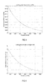
- the pre-masking threshold decreases when the frequency increases. While at a frequency of approximately 100 Hz, a pre-ringing represented by a group delay difference of about 20 ms is acceptable for a listener, at a frequency of approximately 1,500 Hz, the threshold is around 1.5 ms and may reach higher frequencies with an asymptotic end-value of approximately 1 ms.
- the curve shown in Figure 3 can be easily transformed into a limiting phase function, which is shown in Figure 4 as phase difference curve over frequency. By integrating the limiting phase difference function, a corresponding phase frequency characteristic can be derived.
- This phase frequency characteristic may then form the basis for the design of an all-pass filter with a phase frequency characteristic that is the integral of the curve shown in Figure 4 .
- the impulse response of an accordingly designed all-pass filter is depicted in Figure 5
- its corresponding Bode diagram is depicted in Figure 6 .
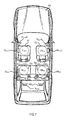
- a setup for generating individual sound zones in a vehicle 705 using the MELMS algorithm may include four sound zones 701-704 corresponding to listening positions (e.g., the seat positions in the vehicle) arranged front left FL Pos , front right FR Pos , rear left RL Pos and rear right RR Pos .
- eight system loudspeakers are arranged more distant from sound zones 701-704.
- two loudspeakers a tweeter/midrange loudspeaker FL Spkr H and a woofer FL Spkr L, are arranged closest to front left position FL Pos and, correspondingly, a tweeter/midrange loudspeaker FR Sprk H and a woofer FR Spkr L are arranged closest to front right position FR Pos .
- broadband loudspeakers SL Spkr and SR Spkr may be arranged next to sound zones corresponding to positions RL Pos and RR Pos , respectively.
- Subwoofers RL Spkr and RR Spkr may be disposed on the rear shelf of the vehicle interior, which, due to the nature of the low-frequency sound generated by subwoofers RL Spkr and RR Spkr , impact all four listening positions front left FL Pos , front right FR Pos , rear left RL Pos and rear right RR Pos .
- vehicle 705 may be equipped with yet other loudspeakers, arranged close to sound zones 701-704, e.g., in the headrests of the vehicle.
- the additional loudspeakers are loudspeakers FLL Spkr and FLR Spkr for zone 701; loudspeakers FRL Spkr and FRR Spkr for zone 702; loudspeakers RLL Spkr and RLR Spkr for zone 703; and loudspeakers RRL Spkr and RRR Spkr for zone 704. All loudspeakers in the setup shown in Figure 7 form respective groups (groups with one loudspeaker) except loudspeaker SL Spkr , which forms a group of passively coupled bass and tweeter speakers, and loudspeaker SR Spkr , which forms a group of passively coupled bass and tweeter speakers (groups with two loudspeakers).
- woofer FL Spkr L may form a group together with tweeter/midrange loudspeaker FL Spkr H and woofer FR Spkr L may form a group together with tweeter/midrange loudspeaker FR Spkr H (groups with two loudspeakers).
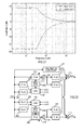
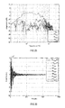
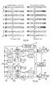
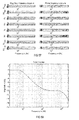
- Figure 8 is a diagram illustrating the magnitude frequency responses at each of the four zones 701-704 (positions) in the setup shown in Figure 7 using equalizer filters, a psychoacoustically motivated pre-ringing constraint module and the system loudspeakers, i.e., FL Spkr H, FL Spkr L, FR Spkr H, FR Spkr L, SL Spkr , SR Spkr , RL Spkr and RR Spkr .
- Figure 9 is an amplitude time diagram (time in samples) illustrating the corresponding impulse responses of the equalizer filters for generating a desired crosstalk cancellation in the respective loudspeaker paths.
- pre-ringing designates the appearance of noise before the actual sound impulse occurs.
- the filter coefficients of the equalizing filters, and thus the impulse responses of the equalizing filters exhibit only little pre-ringing. It can additionally be seen from Figure 8 that the resulting magnitude frequency responses at all desired sound zones tend to deteriorate at higher frequencies, e.g., above 400 Hz.
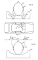
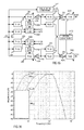
- loudspeakers 1004 and 1005 may be arranged in a close distance d to listener's ears 1002, e.g., below 0.5 m, or even 0.4 or 0.3 m, in order to generate the desired individual sound zones.
- One exemplary way to arrange loudspeakers 1004 and 1005 so close is to integrate loudspeakers 1004 and 1005 into headrest 1003 on which listener's head 1001 may rest.
- Another exemplary way is to dispose (directive) loudspeakers 1101 and 1102 in ceiling 1103, as shown in Figures 11 and 12 .
- Other positions for the loudspeakers may be the B-pillar or C-pillar of the vehicle in combination with loudspeakers in the headrest or the ceiling.
- directional loudspeakers may be used instead of loudspeakers 1004 and 1005 or combined with loudspeakers 1004 and 1005 at the same position as or another position than loudspeakers 1004 and 1005.
- additional loudspeakers FLL Spkr , FLR Spkr , FRL Spkr , FRR Spkr , RLL Spkr , RLR Spkr , RRL Spkr and RRR Spkr may be disposed in the headrests of the seats in positions FL Pos , FR Pos , RL Pos and RR Pos .
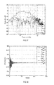
- loudspeakers that are arranged in close distance to a listener's ears such as additional loudspeakers FLL Spkr , FLR Spkr , FRL Spkr , FRR Spkr , RLL Spkr , RLR Spkr , RRL Spkr and RRR Spkr , exhibit an improved magnitude frequency behavior at higher frequencies.
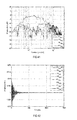
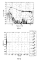
- the crosstalk cancellation is the difference between the upper curve and the three lower curves in Figure 13 .
- pre-ringing is relatively low, as shown in Figure 14 , which illustrates the filter coefficients and thus the impulse responses of all equalizing filters, for providing crosstalk cancellation when using only headrest loudspeakers FLL Spkr , FLR Spkr , FRL Spkr , FRR Spkr , RLL Spkr , RLR Spkr , RRL Spkr and RRR Spkr , and, instead of the pre-ringing constraint, a modeling delay whose delay time may correspond to half of the filter length.
- Pre-ringing can be seen in Figure 14 as noise on the left side of the main impulse.
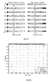
- Arranging loudspeakers in close distance to a listener's ears may in some applications already provide sufficient pre-ringing suppression and sufficient crosstalk cancellation if the modeling delay is sufficiently shortened in psychoacoustic terms, as can be seen in Figures 15 and 16 .
- the pre-ringing can be further decreased without deteriorating the crosstalk cancellation at positions FL Pos , FR Pos , RL Pos and RR Pos (i.e., the inter-position magnitude difference) at higher frequencies.
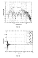
- Figure 17 is a diagram illustrating the magnitude frequency responses at all four sound zones 701-704 using only loudspeakers FL Spkr H, FL Spkr L, FR Spkr H, FR Spkr L, SL Spkr , SR Spkr , RL Spkr and RR Spkr disposed at a distance of more than 0.5 m from positions FL Pos , FR Pos , RL Pos and RR Pos in combination with equalizing filters and the same modeling delay as in the example described in connection with Figures 15 and 16 .
- loudspeakers FLL Spkr , FLR Spkr , FRL Spkr , FRR Spkr , RLL Spkr , RLR Spkr , RRL Spkr and RRR Spkr which are arranged in the headrests with the more distant loudspeakers of the setup shown in Figure 7 , i.e., loudspeakers FL Spkr H, FL Spkr L, FR Spkr H, FR Spkr L, SL Spkr , SR Spkr , RL Spkr and RR Spkr , and, as shown in Figures 19 and 20
- using a pre-ringing constraint instead of a modeling delay with reduced length can further decrease (compare Figures 18 and 20 ) the pre-ringing and increase (compare Figures 17 and 19 ) the crosstalk cancellation at positions FL Pos , FR Pos , RL Pos and RR Pos .
- a stepped curve may also be employed in which, for example, the step width may be chosen to be frequency-dependent according to psychoacoustic aspects such as the Bark scale or the mel scale.
- the Bark scale is a psychoacoustic scale that ranges from one to 24 and corresponds to the first 24 critical bands of hearing. It is related to but somewhat less popular than the mel scale. It is perceived as noise by a listener when spectral drops or narrow-band peaks, known as temporal diffusion, occur within the magnitude frequency characteristic of a transfer function. Equalizing filters may therefore be smoothed during control operations or certain parameters of the filters such as the quality factor may be restricted in order to reduce unwanted noise.
- nonlinear smoothing that approximates the critical bands of human hearing may be employed.
- N relates to the length of the fast Fourier transformation (FFT);
- ⁇ x-1/2 ⁇ relates to rounding up to the next integer;
- nonlinear smoothing is basically frequency-dependent arithmetic averaging whose spectral limits change dependent on the chosen nonlinear smoothing coefficient ⁇ over frequency.
- f [0, ..., fs/2] is the discrete frequency vector of length (N/2+1), N is the length of the FFT, f s is the sampling frequency, MaxGain dB is the maximum valid increase in [dB] and MinGain dB is the minimum valid decrease in [dB].
- MaxGainLim f 10 MaxGainLim dB f 20
- MinGainLim f 10 MinGainLim dB f 20
- a magnitude constraint can be derived that is applicable to the MELMS algorithm in order to generate nonlinear smoothed equalizing filters that suppress spectral peaks and drops in a psychoacoustically acceptable manner.
- An exemplary magnitude frequency constraint of an equalizing filter is shown in Figure 21 , wherein upper limit U corresponds to the maximum valid increase MaxGainLim dB ( f ) and lower limit L corresponds to the minimum allowable decrease MinGainLim dB ( f ) .
- the equalizing filters based on the MELMS algorithm are subject to nonlinear smoothing, as described by the equations below.
- a SS j ⁇ ⁇ 0 A j ⁇ ⁇ 0
- a ⁇ SS j ⁇ ⁇ n ⁇ A ⁇ j ⁇ ⁇ n - 1 ⁇ MaxGainLim n , if A j ⁇ ⁇ n > A ⁇ SS ⁇ j ⁇ ⁇ n - 1 ⁇ MaxGainLim n , A ⁇ j ⁇ ⁇ n - 1 ⁇ MinGainLim n , if A j ⁇ ⁇ n ⁇ A ⁇ SS ⁇ j ⁇ ⁇ n - 1 ⁇ MinGainLim n ,
- a SS ( j ⁇ N-n )* complex conjugate of A SS ( j ⁇ N-n ).
- Magnitude constraint module 2201 is arranged between LMS module 207 and equalizing filter module 205.
- Another magnitude constraint module 2202 is arranged between LMS module 208 and equalizing filter module 206.
- the magnitude constraint may be used in connection with the pre-ringing constraint (as shown in Figure 22 ), but may be also used in standalone applications, in connection with other psychoacoustically motivated constraints or in connection with a modeling delay.
- An alternative way to smooth the spectral characteristic of the equalizing filters may be to window the equalizing filter coefficients directly in the time domain.
- smoothing cannot be controlled according to psychoacoustic standards to the same extent as in the system and methods described above, but windowing of the equalizing filter coefficients allows for controlling the filter behavior in the time domain to a greater extent.
- Figure 27 is a diagram illustrating the magnitude frequency responses at sound zones 701-704 when using equalizing filters and only the more distant loudspeakers, i.e., loudspeakers FL Spkr H, FL Spkr L, FR Spkr H, FR Spkr L, SL Spkr , SR Spkr , RL Spkr and RR Spkr , in combination with a pre-ringing constraint and a magnitude constraint based on windowing with a Gauss window of 0.75.
- the corresponding impulse responses of all equalizing filters are depicted in Figure 28 .
- - N 2 ⁇ n ⁇ N 2 and ⁇ is a parameter that is indirect proportional to the standard deviation ⁇ and that is, for example, 0.75.
- Parameter ⁇ may be seen as a smoothing parameter that has a Gaussian shape (amplitude over time in samples), as shown in Figure 29 .
- a windowing module 3001 (magnitude constraint) is arranged between LMS module 207 and equalizing filter module 205.
- Another windowing module 3002 is arranged between LMS module 208 and equalizing filter module 206. Windowing may be used in connection with the pre-ringing constraint (as shown in Figure 22 ), but may be also used in standalone applications, in connection with other psychoacoustically motivated constraints or in connection with a modeling delay.
- Windowing results in no significant changes in the crosstalk cancellation performance, as can be seen in Figure 27 , but the temporal behavior of the equalizing filters is improved, as can be seen from a comparison of Figures 26 and 28 .
- Using a window as a magnitude constraint does not result in such a huge smoothing of the magnitude frequency curve as with the other version, as will be apparent when comparing Figure 31 with Figures 23 and 24 .
- the phase time characteristic is smoothed since smoothing is performed in the time domain, as will also be apparent when comparing Figure 31 with Figures 23 and 24 .
- Figure 31 is a Bode diagram (magnitude frequency responses, phase frequency responses) of a system or method when only more distant loudspeakers in combination with a pre-ringing constraint and a magnitude constraint based on windowing with the modified Gauss window are used.
- the Gauss window shown in Figure 29 tends to level out when parameter ⁇ gets smaller and thus provides less smoothing at smaller values of parameter ⁇ .
- Parameter ⁇ may be chosen dependent on different aspects such as the update rate (i.e., how often windowing is applied within a certain number of iteration steps), the total number of iterations, etc.
- windowing was performed in each iteration step, which was the reason for choosing a relatively small parameter ⁇ , since repeated multiplications of the filter coefficients with the window are performed in each iteration step and the filter coefficients successively decrease.
- An accordingly modified window is shown in Figure 32 .
- Windowing allows not only for a certain smoothing in the spectral domain in terms of magnitude and phase, but also for adjusting the desired temporal confinement of the equalizing filter coefficients. These effects can be freely chosen by way of a smoothing parameter such as a configurable window (see parameter ⁇ in the exemplary Gauss window described above) so that the maximum attenuation and the acoustic quality of the equalizing filters in the time domain can be adjusted.
- a smoothing parameter such as a configurable window (see parameter ⁇ in the exemplary Gauss window described above) so that the maximum attenuation and the acoustic quality of the equalizing filters in the time domain can be adjusted.
- Yet another alternative way to smooth the spectral characteristic of the equalizing filters may be to provide, in addition to the magnitude, the phase within the magnitude constraint.
- a previously adequately smoothed phase is applied, whereby smoothing may again be nonlinear.
- any other smoothing characteristic is applicable as well. Smoothing may be applied only to the unwrapped phase, which is the continuous phase frequency characteristic, and not to the (repeatedly) wrapped phase, which is within a valid range of - ⁇ ⁇ ⁇ ⁇ ⁇ .
- E' m (e j ⁇ ,n) E m (e j ⁇ ,n)G m (e j ⁇ ) and G m (e j ⁇ ) is the weighting function for the m th error signal in the spectral domain.
- a flow chart of an accordingly modified MELMS algorithm which is based on the system and method described above in connection with Figure 22 and in which a spatial constraint LMS module 3301 substitutes LMS module 207 and a spatial constraint LMS module 3302 substitutes LMS module 208, is shown in Figure 33 .
- the spatial constraint may be used in connection with the pre-ringing constraint (as shown in Figure 33 ), but may also be used in standalone applications, in connection with psychoacoustically motivated constraints or in connection with a modeling delay.
- a flow chart of an alternatively modified MELMS algorithm which is also based on the system and method described above in connection with Figure 22 , is shown in Figure 34 .
- a spatial constraint module 3403 is arranged to control a gain control filter module 3401 and a gain control filter module 3402.
- Gain control filter module 3401 is arranged downstream of microphone 215 and provides a modified error signal e' 1 (n).
- Gain control filter module 3402 is arranged downstream of microphone 216 and provides a modified error signal e' 2 (n).
- (error) signals e 1 (n) and e 2 (n) from microphones 215 and 216 are modified in the time domain rather than in the spectral domain.
- the modification in the time domain can nevertheless be performed such that the spectral composition of the signals is also modified, e.g., by way of the filter that provides a frequency-dependent gain.
- the gain may also simply be frequency independent.
- no spatial constraint i.e., all error microphones (all positions, all sound zones) are weighted equally so that no special emphasis or insignificance is applied to particular microphones (positions, sound zones).
- a position-dependent weighting can be applied as well.
- sub-areas may be defined so that, for example, areas around the listener's ears may be amplified and areas at the back part of the head may be damped.
- the loudspeakers may exhibit differing electrical and acoustic characteristics. But even if all characteristics are identical, it may be desirable to control the bandwidth of each loudspeaker independently from the other loudspeakers since the usable bandwidths of identical loudspeakers with identical characteristics may differ when disposed at different locations (positions, vented boxes with different volume). Such differences may be compensated by way of crossover filters.
- a frequency-dependent gain constraint herein also referred to as a frequency constraint, may be used instead of crossover filters to make sure that all loudspeakers are operated in an identical or at least similar fashion, e.g., such that none of the loudspeakers are overloaded, which leads to unwanted nonlinear distortions.
- Frequency constraints can be realized in a multiplicity of ways, two of which are discussed below.
- FIG. 35 A flow chart of an accordingly modified MELMS algorithm, which is based on the system and method described above in connection with Figure 34 , but may be based on any other system and method described herein, with or without particular constraints, is shown in Figure 35 .
- k 1, ..., K, K being the number of loudspeakers
- m 1, ..., M , M being the number of microphones
- ⁇ k,m ( e j ⁇ ,n ) is the model of the secondary path between the k th loudspeaker and the m th (error) microphone at time n (in samples);
- is the magnitude of the crossover filter for the spectral restriction of the signal supplied to the k th loudspeaker, the signal being essentially constant over time n.
- the modified MELMS algorithm is essentially only a modification with which filtered input signals are generated, wherein the filtered input signals are spectrally restricted by way of K crossover filter modules with a transfer function F k ( e j ⁇ ).
- the crossover filter modules may have complex transfer functions, but in most applications, it is sufficient to use only the magnitudes of transfer functions
- the magnitude of exemplary frequency characteristics of applicable crossover filters are depicted in Figure 36 .
- the corresponding magnitude frequency responses at all four positions and the filter coefficients of the equalizing filters (representing the impulse responses thereof) over time (in samples), are shown in Figures 37 and 38 , respectively.
- the magnitude responses shown in Figure 37 and the impulse responses of the equalizing filters for establishing crosstalk cancellation shown in Figure 38 relate to four positions when applying equalizing filters in connection with exclusively more distant loudspeakers such as loudspeakers FL Spkr H, FL Spkr L, FR Spkr H, FR Spkr L, SL Spkr , SR Spkr , RL Spkr and RR Spkr in the setup shown in Figure 7 in combination with a frequency constraint, a pre-ringing constraint and a magnitude constraint, including windowing with a Gauss window of 0.25.
- Figures 37 and 38 illustrate the results of the spectral restriction of the output signals by way of the crossover filter modules below 400 Hz, which is the minor influence of the front woofers FL Spkr L and FR Spkr L in the setup shown in Figure 7 , and the absence of any significant influence on the crosstalk cancellation, as can be seen from a comparison of Figures 37 and 27 . These results are also supported when comparing the Bode diagrams shown in Figures 39 and 31 , in which the diagrams shown in Figure 39 are based on the same setup that forms the basis of Figures 37 and 38 and shows a significant change of the signal supplied to woofers FL Spkr L and FR Spkr L when they are next to front positions FL Pos and FR Pos .
- Systems and methods with frequency constraints as set forth above may tend to exhibit a certain weakness (magnitude drops) at low frequencies in some applications. Therefore, the frequency constraint may be alternatively implemented, e.g., as discussed below in connection with Figure 40 .
- a flow chart of an accordingly modified MELMS algorithm, as shown in Figure 40 is based on the system and method described above in connection with Figure 34 , but may be alternatively based on any other system and method described herein, with or without particular constraints.
- a frequency constraint module 4001 may be arranged downstream of equalizing filter 205
- a frequency constraint module 4002 may be arranged downstream of equalizing filter 206.
- the alternative arrangement of the frequency constraint allows for reducing the complex influence (magnitude and phase) of the crossover filters in the room transfer characteristics, i.e., in the actual occurring transfer functions S k,m ( e j ⁇ , n ) by way of prefiltering the signals supplied to the loudspeakers, and in the transfer functions of their models ⁇ k,m ( e j ⁇ , n ), which is indicated in Figure 40 by ⁇ ' k,m ( e j ⁇ , n ).
- Figure 41 is a diagram illustrating the magnitude frequency responses at the four positions described above in connection with Figure 7 when equalizing filters are applied and only the more distant loudspeakers, i.e., FL Spkr H, FL Spkr L, FR Spkr H, FR Spkr L, SL Spkr , SR Spkr , RL Spkr and RR Spkr in the setup shown in Figure 7 , are used in connection with a pre-ringing constraint, a magnitude constraint (windowing with a Gauss window of 0.25) and a frequency constraint that is included in the room transfer functions.
- the corresponding impulse responses are shown in Figure 42
- the corresponding Bode diagrams are shown in Figure 43 .
- the crossover filters have a significant impact on woofers FL Spkr L and FR Spkr L next to front positions FL Pos and FR Pos .
- the frequency constraint on which the diagram of Figure 41 is based allows for a more distinct filtering effect at lower frequencies and that the crosstalk cancellation performance deteriorates a little bit at frequencies above 50 Hz.
- At least one (other) psychoacoustically motivated constraint may be employed, either alone or in combination with other psychoacoustically motivated or not psychoacoustically motivated constraints such as a loudspeaker-room-microphone constraint.
- a magnitude constraint i.e., non-linear smoothing of the magnitude frequency characteristic when maintaining the original phase
- This post-ringing may be suppressed by way of a post-ringing constraint, which can be described based on an energy time curve (ETC) as follows:
- w k is the final set of filter coefficients for the k th equalizing filter in a MELMS algorithm with length N/2, and 0 is the zero column vector with length N.
- W k,t ( e j ⁇ ) is the real part of the spectrum of the k th equalizing filter at the t th iteration step (rectangular window) and ETC dB k N 2 ⁇ N 2 n ⁇ t represents the waterfall diagram of the k th equalizing filter, which includes all N/2 magnitude frequency responses of the single sideband spectra with a length of N/2 in the logarithmic domain.
- Auditory masking occurs when the perception of one sound is affected by the presence of another sound. Auditory masking in the frequency domain is known as simultaneous masking, frequency masking or spectral masking. Auditory masking in the time domain is known as temporal masking or non-simultaneous masking.
- the unmasked threshold is the quietest level of the signal that can be perceived without a present masking signal.
- the masked threshold is the quietest level of the signal perceived when combined with a specific masking noise.
- the amount of masking is the difference between the masked and unmasked thresholds. The amount of masking will vary depending on the characteristics of both the target signal and the masker, and will also be specific to an individual listener.
- Simultaneous masking occurs when a sound is made inaudible by a noise or unwanted sound of the same duration as the original sound.
- Temporal masking or non-simultaneous masking occurs when a sudden stimulus sound makes other sounds that are present immediately preceding or following the stimulus inaudible.
- Masking that obscures a sound immediately preceding the masker is called backward masking or pre-masking, and masking that obscures a sound immediately following the masker is called forward masking or post-masking.
- Temporal masking's effectiveness attenuates exponentially from the onset and offset of the masker, with the onset attenuation lasting approximately 20 ms and the offset attenuation lasting approximately 100 ms, as shown in Figure 44 .
- FIG. 45 An exemplary graph depicting the inverse exponential function of the group delay difference over frequency is shown in Figure 45 , and the corresponding inverse exponential function of the phase difference over frequency as the post-masking threshold is shown in Figure 46 .
- "Post-masking" threshold is understood herein as a constraint to avoid post-ringing in equalizing filters.
- Figure 45 which shows a constraint in the form of a limiting group delay function (group delay differences over frequency)
- the post-masking threshold decreases when the frequency increases.
- t S 0 ⁇ N 2 ⁇ f S ... N 2 - 1 is the time vector with a length of N/2 (in samples),
- GroupDelay ( n ) is the difference function of the group delay for suppressing post-ringing (in s) at frequency n (in FFT bin).
- 0 is the zero vector with length t Max .
- t Max is the time index in which the n th limiting function has its maximum.
- ETC k n ⁇ t ⁇ LimFct n ⁇ t ETC k n ⁇ t ⁇ ETC k n ⁇ t , if ETC dBk n ⁇ t > LimFct n ⁇ t ETC k n ⁇ t , otherwise .
- the post-ringing constraint is based here on a temporal restriction of the ETC, which is frequency dependent and whose frequency dependence is based on group delay difference function ⁇ GroupDelay ( n ).
- An exemplary curve representing group delay difference function ⁇ GroupDelay ( n ) is shown in Figure 45 .
- the level of a limiting function LimFct dB ( n, t) shall decrease according to thresholds a0 dB and a1 db , as shown in Figure 47 .
- a temporal limiting function such as the one shown in Figure 47 is calculated and applied to the ETC matrix. If the value of the corresponding ETC time vector exceeds the corresponding threshold given by LimFct dB ( n, t) at frequency n, the ETC time vector is scaled according to its distance from the threshold. In this way, it is assured that the equalizing filters exhibit in their spectra a frequency-dependent temporal drop, as required by group delay difference function ⁇ GroupDelay ( n ).
- group delay difference function ⁇ GroupDelay ( n ) is designed according to psychoacoustic requirements (see Figure 44 ), post-ringing, which is annoying to a listener, can be avoided or at least reduced to an acceptable degree.
- the post-ringing constraint can be implemented, for example, in the system and method described above in connection with Figure 40 (or in any other system and method described herein).
- combined magnitude and post-ringing constraint modules 4801 and 4802 are used instead of magnitude constraint modules 2201 and 2202.
- Figure 49 is a diagram illustrating the magnitude frequency responses at the four positions described above in connection with Figure 7 when equalizing filters are applied and only the more distant loudspeakers, i.e., FL Spkr H, FL Spkr L, FR Spkr H, FR Spkr L, SL Spkr , SR Spkr , RL Spkr and RR Spkr in the setup shown in Figure 7 , are used in connection with a pre-ringing constraint, a magnitude constraint (windowing with a Gauss window of 0.25), a frequency constraint that is included in the room transfer functions and a post-ringing constraint.
- a pre-ringing constraint i.e., FL Spkr H, FL Spkr L, FR Spkr H, FR Spkr L, SL Spkr , SR Spkr , RL Spkr and RR Spkr in the setup shown in Figure 7 .
- Another way to implement the post-ringing constraint is to integrate it in the windowing procedure described above in connection with the windowed magnitude constraint.
- the post-ringing constraint in the time domain is spectrally windowed in a similar manner as the windowed magnitude constraint so that both constraints can be merged into one constraint.
- each equalizing filter is filtered exclusively at the end of the iteration process, beginning with a set of cosine signals with equidistant frequency points similar to an FFT analysis. Afterwards, the accordingly calculated time signals are weighted with a frequency-dependent window function.
- the window function may shorten with increasing frequency so that filtering is enhanced for higher frequencies and thus nonlinear smoothing is established.
- an exponentially sloping window function can be used whose temporal structure is determined by the group delay, similar to the group delay difference function depicted in Figure 45 .
- the implemented window function which is freely parameterizable and whose length is frequency dependent, may be of an exponential, linear, Hamming, Hanning, Gauss or any other appropriate type.
- the window functions used in the present examples are of the exponential type.
- Endpoint a1 dB of the limiting function may be frequency dependent (e.g., a frequency-dependent limiting function a1 dB (n) in which a1 dB (n) may decrease when n increases) in order to improve the crosstalk cancellation performance.
- the windowing function may be further configured such that within a time period defined by group delay function ⁇ GroupDelay ( n ), the level drops to a value specified by frequency-dependent endpoint a1 dB (n), which may be modified by way of a cosine function. All accordingly windowed cosine signals are subsequently summed up, and the sum is scaled to provide an impulse response of the equalizing filter whose magnitude frequency characteristic appears to be smoothed (magnitude constraint) and whose decay behavior is modified according to a predetermined group delay difference function (post-ringing constraint). Since windowing is performed in the time domain, it affects not only the magnitude frequency characteristic, but also the phase frequency characteristic so that frequency-dependent nonlinear complex smoothing is achieved.
- the windowing technique can be described by the equations set forth below.
- t S 0 ⁇ N 2 ⁇ f S ... N 2 - 1 is the time vector with a length of N/2 (in samples),
- CosMat ( n, t) cos ( 2 ⁇ nt S ) is the cosine signal matrix.
- m n a ⁇ 1 dB n - a ⁇ 0 dB ⁇ GroupDelay n - t 0 is the gradient of the limiting function in dB/s,
- GroupDelay ( n ) is the group delay difference function for suppressing post-ringing at the n th frequency bin
- CosMat n ⁇ t is the cosine matrix filter, wherein w k is the k th equalizing filter with length N/2.
- the magnitude time curves of an exemplary frequency-dependent level limiting function a1 dB (n) and an exemplary level limit LimLev dB ( n ) are depicted in Figure 52 .
- Level limiting function a1 dB (n) has been amended according to level modification function LevModFct dB ( n ), shown as the amplitude frequency curve in Figure 53 , to the effect that the lower frequencies have been less limited than the upper frequencies.
- the windowing functions WinMat(n,t), based on exponential windows, are illustrated in Figure 54 at frequencies 200 Hz (a), 2,000 Hz (b) and 20,000 Hz (c). Magnitude and post-ringing constraints can thus be combined with each other without any significant performance drops, as can further be seen in Figures 55-57 .
- Figure 55 is a diagram illustrating the magnitude frequency responses at the four positions described above in connection with Figure 7 when equalizing filters are applied and only the more distant loudspeakers, i.e., FL Spkr H, FL Spkr L, FR Spkr H, FR Spkr L, SL Spkr , SR Spkr , RL Spkr and RR Spkr in the setup shown in Figure 7 , are used in connection with a pre-ringing constraint, a frequency constraint, a windowed magnitude and a post-ringing constraint.
- the corresponding impulse responses (amplitude time diagram) are shown in Figure 56
- the corresponding Bode diagrams are shown in Figure 57 .
- windowing technique allows for a significant reduction of spectral components at higher frequencies, which is perceived by the listener as more convenient. It has to be noted that this special windowing technique is not only applicable in MIMO systems, but can also be applied to any other system and method that use constraints such as general equalizing systems or measurement systems.
- all loudspeakers including the eight loudspeakers disposed in the headrests, are employed to assess the performance of a windowed post-ringing constraint in view of the crosstalk cancellation performance. It is assumed that a bright zone is established at the front left position and three dark zones are generated at the three remaining positions.
- Figure 58 illustrates, by way of a magnitude frequency curve, a target function that is the reference for tonality in the bright zone and may be simultaneously applied to the pre-ringing constraint.
- the impulse responses of an exemplary equalizer filter based on the target function shown in Figure 58 with and without applied windowing (windowed post-ringing constraint) are depicted in Figure 59 as amplitude time curves in the linear domain and in Figure 60 as magnitude time curves in the logarithmic domain. It is apparent from Figure 60 that the windowed post-ringing constraint is capable of significantly reducing the decay time of the equalizing filter coefficients and thus of the impulse responses of the equalizing filters based on the MELMS algorithm.
- Figure 61 is a diagram illustrating the magnitude frequency responses at the four positions described above in connection with Figure 7 when using all loudspeakers (including the loudspeakers in the headrests) in the setup shown in Figure 7 and equalizing filters in combination with a pre-ringing constraint, a frequency constraint, a windowed magnitude and a windowed post-ringing constraint.
- the corresponding impulse responses are shown in Figure 62 .
- all types of psychoacoustic constraints such as pre-ringing constraints, magnitude constraints, post-ringing constraints and all types of loudspeaker-room-microphone constraints such as frequency constraints and spatial constraints may be combined as required.
- the system and method described above in connection with Figure 1 may be modified not only to generate individual sound zones, but also to generate any desired wave fields (known as auralization).
- the system and method shown in Figure 1 has been modified in view of primary path 101, which has been substituted by controllable primary path 6301.
- Primary path 6301 is controlled according to source room 6302, e.g., a desired listening room.
- the secondary path may be implemented as a target room such as the interior of vehicle 6303.
- the exemplary system and method shown in Figure 63 is based on a simple setup in which the acoustics of desired listening room 6302 (e.g., a concert hall) are established (modeled) within a sound zone around one particular actual listening position with the same setup as shown in Figure 7 (e.g., the front left position in vehicle interior 6303).
- a listening position may be the position of a listener's ear , a point between a listener's two ears or the area around the head at a certain position in the target room 6303.
- Acoustic measurements in the source room and in the target room may be made with the same microphone constellation, i.e., the same number of microphones with the same acoustic properties, and disposed at the same positions relative to each other.
- the MELMS algorithm generates coefficients for K equalizing filters that have transfer function W(z)
- the same acoustic conditions may be present at the microphone positions in the target room as at the corresponding positions in the source room.
- this means that a virtual center speaker may be created at the front left position of target room 6303 that has the same properties as measured in source room 6302.
- the system and method described above may thus also be used for generating several virtual sources, as can be seen in the setup shown in Figure 64 .
- front left loudspeaker FL and front right loudspeaker FR correspond to loudspeaker arrays with high-frequency loudspeakers FL Spkr H and FR Sprk H and low-frequency loudspeakers FL Spkr L and FR Spkr L, respectively.
- both source room 6401 and target room 6303 may be 5.1 audio setups.
- a multiplicity I of virtual sources may also be modeled simultaneously, wherein for each of the I virtual sources, a corresponding equalizing filter coefficient set W i (z), I being 0, ..., I-1, is calculated.
- W i (z) a corresponding equalizing filter coefficient set
- I 6 virtual sources are generated that are disposed according to the ITU standard for 5.1 systems.
- the approach for systems with a multiplicity of virtual sources is similar to the approach for systems with only one virtual source, which is that I primary path matrixes P i (z) are determined in the source room and applied to the loudspeaker set up in the target room.
- a set of equalizing filter coefficients W i (z) for K equalizing filters is adaptively determined for each matrix P i (z) by way of the modified MELMS algorithm.
- the I x K equalizing filters are then superimposed and applied, as shown in Figure 65 .
- I 6 virtual sound sources for the approximate sound reproduction according to the 5.1 standard at the driver's position.
- Corresponding output signals of the filter matrixes are summed up by way of adders 6507-6521 and are then supplied to the respective loudspeakers arranged in target room 6303.
- a wave field can be established in any number of positions, e.g., microphone arrays 6603-6606 at four positions in a target room 6601, as shown in Figure 66 .
- the microphone arrays providing 4 x M are summed up in a summing module 6602 to provide M signals y(n) to subtractor 105.
- the modified MELMS algorithm allows not only for control of the position of the virtual sound source, but also for the horizontal angle of incidence (azimuth), the vertical angle of incidence (elevation) and the distance between the virtual sound source and the listener.
- the field may be coded into its eigenmodes, i.e., spherical harmonics, which are subsequently decoded again to provide a field that is identical or at least very similar to the original wave field.
- the wave field may be dynamically modified, e.g., rotated, zoomed in or out, clinched, stretched, shifted back and forth, etc.
- These eigenmodes may be modeled by way of specific sets of equalizing filter coefficients to a certain degree (order).
- the order basically depends on the sound system present in the target room such as the sound system's upper cutoff frequency. The higher the cutoff frequency is, the higher the order should be.
- f Lim cM 2 ⁇ ⁇ ⁇ R , wherein c is the speed of sound (343 m/s at 20° C), M is the order of the eigenmodes, N is the number of eigenmodes and R is the radius of the listening surface of the zones.
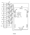
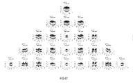
- the complex spherical harmonics Y m , n ⁇ ⁇ ⁇ ⁇ may then be modeled by the MIMO system and method in the target room, i.e., by the corresponding equalizing filter coefficients, as depicted in Figure 68 .
- the Ambisonic coefficients B m , n ⁇ are derived from an analysis of the wave field in the source room or a room simulation.
- Equalizing filter matrixes 6801-6803 provide the first three spherical harmonics (W,X and Y) of a virtual sound source for the approximate sound reproduction at the driver's position from input signal x[n].
- Equalizing filter matrixes 6801-6803 provide three sets of equalizing filter coefficients W 1 (z)-W 3 (z) in which each set includes K equalizing filters and thus provides K output signals.
- Corresponding output signals of the filter matrixes are summed up by way of adders 6804-6809 and then supplied to the respective loudspeakers arranged in target room 6814.
- the first three eigenmodes X, Y and Z are generated that together form the desired wave field of one virtual source.
- an arrangement for measuring the acoustics of the source room may include microphone array 6901 in which a multiplicity of microphones 6903-6906 are disposed on a headband 6902.
- Headband 6902 may be worn by a listener 6907 when in the source room and positioned slightly above the listener's ears.
- the microphone arrays include at least two microphones arranged on a circle with a diameter corresponding to the diameter of an average listener's head and in a position that corresponds to an average listener's ears. Two of the array's microphones may be disposed at or at least close to the position of the average listener's ears.
- Figure 70 depicts a microphone array including a multiplicity of microphones 7002 on rigid sphere 7001 in which some of microphones 7002 may be arranged on at least one circle 7003.
- Circle 7003 may be arranged such that it corresponds to a circle that includes the positions of a listener's ears.
- a multiplicity of microphones may be arranged on a multiplicity of circles that include the positions of the ears but that the multiplicity of microphones concentrates to the areas around where the human ears are or would be in case of an artificial head or other rigid sphere.
- An example of an arrangement in which microphones 7102 are arranged on ear cups 7103 worn by listener 7101 is shown in Figure 71 .
- Microphones 7102 may be disposed in a regular pattern on a hemisphere around the positions of the human ears.
- microphone arrangements for measuring the acoustics in the source room may include artificial heads with two microphones at the ears' positions, microphones arranged in planar patterns or microphones placed in a (quasi-)regular fashion on a rigid sphere, able to directly measure the Ambisonic coefficients.
- an exemplary process for providing a magnitude constraint with integrated post-ringing constraint as shown in Figure 72 may include iteratively adapting the transfer function of the filter module (7201), inputting a set of cosine signals with equidistant frequencies and equal amplitudes into the filter module upon adaption (7202), weighting signals output by the filter module with a frequency-dependent windowing function (7203), summing up the filtered and windowed cosine signals to provide a sum signal (7204), and scaling the sum signal to provide an updated impulse response of the filter module for controlling the transfer functions of the K equalizing filter modules (7205).
- both the filter modules and the filter control modules may be implemented in a vehicle but alternatively only the filter modules may be implemented in the vehicle and the filter control modules may be outside the vehicle. As another alternative both the filter modules and the filter control modules may be implemented outside vehicle, e.g., in a computer and the filter coefficients of the filter module may be copied into a shadow filter disposed in the vehicle.
- the adaption may be a one-time process or a consecutive process as the case may be.
Landscapes
- Physics & Mathematics (AREA)
- Engineering & Computer Science (AREA)
- Acoustics & Sound (AREA)
- Signal Processing (AREA)
- Circuit For Audible Band Transducer (AREA)
- Soundproofing, Sound Blocking, And Sound Damping (AREA)
- Fittings On The Vehicle Exterior For Carrying Loads, And Devices For Holding Or Mounting Articles (AREA)
- Stereophonic System (AREA)
Abstract
Description
- The disclosure relates to a system and method for generating a sound wave field.
- Spatial sound field reproduction techniques utilize a multiplicity of loudspeakers to create a virtual auditory scene over a large listening area. Several sound field reproduction techniques, e.g., wave field synthesis (WFS) or Ambisonics, make use of a loudspeaker array equipped with a plurality of loudspeakers to provide a highly detailed spatial reproduction of an acoustic scene. In particular, wave field synthesis is used to achieve a highly detailed spatial reproduction of an acoustic scene to overcome limitations by using an array of, e.g., several tens to hundreds of loudspeakers.
- Spatial sound field reproduction techniques overcome some of the limitations of stereophonic reproduction techniques. However, technical constraints prohibit the employment of a high number of loudspeakers for sound reproduction. Wave field synthesis (WFS) and Ambisonics are two similar types of sound field reproduction. Though they are based on different representations of the sound field (the Kirchhoff-Helmholtz integral for WFS and the spherical harmonic expansion for Ambisonics), their aim is congruent and their properties are alike. Analysis of the existing artifacts of both principles for a circular setup of a loudspeaker array came to the conclusion that HOA (Higher-Order Ambisonics), or more exactly near-field-corrected HOA, and WFS meet similar limitations. Both WFS and HOA and their unavoidable imperfections cause some differences in terms of the process and quality of the perception. In HOA, with a decreasing order of the reproduction, the impaired reconstruction of the sound field will probably result in a blur of the localization focus and a certain reduction in the size of the listening area.
- For audio reproduction techniques such as wave field synthesis (WFS) or Ambisonics, the loudspeaker signals are typically determined according to an underlying theory, so that the superposition of sound fields emitted by the loudspeakers at their known positions describes a certain desired sound field. Typically, the loudspeaker signals are determined assuming free-field conditions. Therefore, the listening room should not exhibit significant wall reflections, because the reflected portions of the reflected wave field would distort the reproduced wave field. In many scenarios such as the interior of a car, the necessary acoustic treatment to achieve such room properties may be too expensive or impractical.
- A system is configured to generate a sound wave field around a listening position in a target loudspeaker-room-microphone system in which a loudspeaker array of K ≥ 1 groups of loudspeakers, with each group of loudspeakers having at least one loudspeaker, is disposed around the listening position, and a microphone array of M ≥ 1 groups of microphones, with each group of microphones having at least one microphone, is disposed at the listening position. The system includes K equalizing filter modules that are arranged in signal paths upstream of the groups of loudspeakers and downstream of an input signal path and that have controllable transfer functions. The system further includes K filter control modules that are arranged in signal paths downstream of the groups of microphones and downstream of the input signal path and that control the transfer functions of the K equalizing filter modules according to an adaptive control algorithm based on error signals from the K groups of microphones and an input signal on the input signal path. M primary path modeling modules are arranged in signal paths upstream of the groups of microphones and downstream of the input signal path and are configured to model the primary paths present in a desired source loudspeaker-room-microphone system.
- A method is configured to generate a sound wave field around a listening position in a target loudspeaker-room-microphone system in which a loudspeaker array of K ≥ 1 groups of loudspeakers, with each group of loudspeakers having at least one loudspeaker, is disposed around the listening position, and a microphone array of M ≥ 1 groups of microphones, with each group of microphones having at least one microphone, is disposed at the listening position. The method includes equalizing filtering with controllable transfer functions in signal paths upstream of the K groups of loudspeakers and downstream of an input signal path, and controlling with equalization control signals of the controllable transfer functions for equalizing filtering according to an adaptive control algorithm based on error signals from the K groups of microphones and an input signal on the input signal path. The method further includes modeling of primary paths present in a desired source loudspeaker-room-microphone system in signal paths upstream of the groups of microphones and downstream of the input path.
- Other systems, methods, features and advantages will be, or will become, apparent to one with skill in the art upon examination of the following figures and detailed description. It is intended that all such additional systems, methods, features and advantages be included within this description, be within the scope of the invention, and be protected by the following claims.
- The system and methods may be better understood with reference to the following drawings and description. The components in the figures are not necessarily to scale, emphasis instead being placed upon illustrating the principles of the invention. Moreover, in the figures, like referenced numerals designate corresponding parts throughout the different views.
-
Figure 1 is a flow chart illustrating a simple acoustic Multiple-Input Multiple-Output (MIMO) system with M recording channels (microphones) and K output channels (loudspeakers), including a multiple error least mean square (MELMS) system or method. -
Figure 2 is a flowchart illustrating a 1 x 2 x 2 MELMS system or method applicable in the MIMO system shown inFigure 1 . -
Figure 3 is a diagram illustrating a pre-ringing constraint curve in the form of a limiting group delay function (group delay differences over frequency). -
Figure 4 is a diagram illustrating the curve of a limiting phase function (phase difference curve over frequency) derived from the curve shown inFigure 3 . -
Figure 5 is an amplitude time diagram illustrating the impulse response of an all-pass filter designed according to the curve shown inFigure 4 . -
Figure 6 is a Bode diagram illustrating the magnitude and phase behavior of the all-pass filter shown inFigure 5 . -
Figure 7 is a block diagram illustrating a setup for generating individual sound zones in a vehicle. -
Figure 8 is a magnitude frequency diagram illustrating the magnitude frequency responses at each of the four zones (positions) in the setup shown inFigure 7 using a MIMO system solely based on more distant loudspeakers. -
Figure 9 is an amplitude time diagram (time in samples) illustrating the corresponding impulse responses of the equalizer filters of the MIMO system that forms the basis of the diagram shown inFigure 8 . -
Figure 10 is a schematic diagram of a headrest with integrated close-distance loudspeakers applicable in the setup shown inFigure 7 . -
Figure 11 is a schematic diagram of an alternative arrangement of close-distance loudspeakers in the setup shown inFigure 7 . -
Figure 12 is a schematic diagram illustrating the alternative arrangement shown inFigure 11 in more detail. -
Figure 13 is a magnitude frequency diagram illustrating the frequency characteristics at the four positions in the setup shown inFigure 7 when a modeling delay of half the filter length and only close-distance loudspeakers are used. -
Figure 14 is an amplitude time diagram illustrating the impulse responses corresponding to the equalization filter of the MIMO system, which results in the frequency characteristics at the four desired positions shown inFigure 13 . -
Figure 15 is a magnitude frequency diagram illustrating the frequency characteristics at the four positions in the setup shown inFigure 7 when a length-reduced modeling delay and only close-distance loudspeakers are used. -
Figure 16 is an amplitude time diagram illustrating the impulse responses corresponding to the equalization filter of the MIMO system, which results in the frequency characteristics at the four desired positions shown inFigure 15 . -
Figure 17 is a magnitude frequency diagram illustrating the frequency characteristics at the four positions in the setup shown inFigure 7 when a length-reduced modeling delay and only system, i.e., far-distance, loudspeakers are used. -
Figure 18 is an amplitude time diagram illustrating the impulse responses corresponding to the equalization filter of the MIMO system, which results in the frequency characteristics at the four desired positions shown inFigure 17 . -
Figure 19 is a magnitude frequency diagram illustrating the frequency characteristics at the four positions in the setup shown inFigure 7 when an all-pass filter implementing the pre-ringing constraint instead of a modeling delay and only close-distance loudspeakers are used. -
Figure 20 is an amplitude time diagram illustrating the impulse responses corresponding to the equalization filter of the MIMO system, which results to the frequency characteristics at the four desired positions shown inFigure 19 . -
Figure 21 is an amplitude frequency diagram illustrating the upper and lower thresholds of an exemplary magnitude constraint in the logarithmic domain. -
Figure 22 is a flow chart of a MELMS system or method with a magnitude constraint that is based on the system and method described above in connection withFigure 2 . -
Figure 23 is a Bode diagram (magnitude frequency responses, phase frequency responses) of the system or method using a magnitude constraint, as shown inFigure 22 . -
Figure 24 is a Bode diagram (magnitude frequency responses, phase frequency responses) of a system or method using no magnitude constraint. -
Figure 25 is a magnitude frequency diagram illustrating the frequency characteristics at the four positions in the setup shown inFigure 7 when only the eight more distant loudspeakers in combination with a magnitude and pre-ringing constraint are used. -
Figure 26 is an amplitude time diagram illustrating the impulse responses corresponding to the equalization filter of the MIMO system, which results in the frequency characteristics at the four desired positions shown inFigure 25 . -
Figure 27 is a magnitude frequency diagram illustrating the frequency characteristics at the four positions in the setup shown inFigure 7 when only more distant loudspeakers in combination with a pre-ringing constraint and a magnitude constraint based on windowing with a Gauss window are used. -
Figure 28 is an amplitude time diagram illustrating the impulse responses corresponding to the equalization filter of the MIMO system, which results in the frequency characteristics at the four desired positions shown inFigure 27 . -
Figure 29 is an amplitude time diagram illustrating an exemplary Gauss window. -
Figure 30 is a flow chart of a MELMS system or method with a windowing magnitude constraint that is based on the system and method described above in connection withFigure 2 . -
Figure 31 is a Bode diagram (magnitude frequency responses, phase frequency responses) of a system or method when only more distant loudspeakers in combination with a pre-ringing constraint and a magnitude constraint based on windowing with the modified Gauss window are used. -
Figure 32 is an amplitude time diagram illustrating an exemplary modified Gauss window. -
Figure 33 is a flow chart of a MELMS system or method with a spatial constraint that is based on the system and method described above in connection withFigure 22 . -
Figure 34 is a flow chart of a MELMS system or method with an alternative spatial constraint that is based on the system and method described above in connection withFigure 22 . -
Figure 35 is a flow chart of a MELMS system or method with a frequency-dependent gain constraint LMS, which is based on the system and method described above in connection withFigure 34 . -
Figure 36 is a magnitude frequency diagram illustrating the frequency-dependent gain constraints corresponding to four more distant loudspeakers when using crossover filters. -
Figure 37 is a magnitude frequency diagram illustrating the frequency characteristics at the four positions in the setup shown inFigure 7 when only more distant loudspeakers in combination with a pre-ringing constraint, a windowed magnitude constraint and an adaptive frequency (dependent gain) constraint are used. -
Figure 38 is an amplitude time diagram illustrating the impulse responses corresponding to the equalization filter of the MIMO system, which results in the frequency characteristics at the four desired positions shown inFigure 37 . -
Figure 39 is a Bode diagram of a system or method when only more distant loudspeakers in combination with a pre-ringing constraint, a windowed magnitude constraint and an adaptive frequency (dependent gain) constraint are used. -
Figure 40 is a flow chart of a MELMS system or method that is based on the system and method described above in connection withFigure 34 , with an alternative frequency (dependent gain) constraint. -
Figure 41 is a magnitude frequency diagram illustrating the frequency characteristics at the four positions in the setup shown inFigure 7 , with applied equalizing filters when only more distant loudspeakers in combination with a pre-ringing constraint, a windowed magnitude constraint and the alternative frequency (dependent gain) constraint in the room impulse responses are used. -
Figure 42 is an amplitude time diagram illustrating the impulse responses corresponding to the equalization filter of the MIMO system, which results in the frequency characteristics at the four desired positions shown inFigure 41 . -
Figure 43 is a Bode diagram of the equalizing filters applied to the setup shown inFigure 7 when only more distant loudspeakers in combination with a pre-ringing constraint, a windowed magnitude constraint and the alternative frequency (dependent gain) constraints in the room impulse responses are used. -
Figure 44 is a schematic diagram illustrating the sound pressure levels over time for pre-masking, simultaneous masking and post-masking. -
Figure 45 is a diagram illustrating a post-ringing constraint curve in the form of a limiting group delay function as group delay differences over frequency. -
Figure 46 is a diagram illustrating the curve of a limiting phase function as phase difference curve over frequency derived from the curve shown inFigure 45 . -
Figure 47 is a level time diagram illustrating the curve of an exemplary temporal limiting function. -
Figure 48 is a flow chart of a MELMS system or method that is based on the system and method described above in connection withFigure 40 , with a combined magnitude post-ringing constraint. -
Figure 49 is a magnitude frequency diagram illustrating the frequency characteristics at the four positions in the setup shown inFigure 7 , with applied equalizing filters when only more distant loudspeakers in combination with a pre-ringing constraint, a magnitude constraint-based non-linear smoothing, a frequency (dependent gain) constraint and a post-ringing constraint are used. -
Figure 50 is an amplitude time diagram illustrating the impulse responses corresponding to the equalization filter of the MIMO system, which results in the frequency characteristics at the four desired positions shown inFigure 49 . -
Figure 51 is a Bode diagram of the equalizing filters applied to the setup shown inFigure 7 when only more distant loudspeakers in combination with a pre-ringing constraint, a magnitude constraint-based non-linear smoothing, a frequency (dependent gain) constraint and a post-ringing constraint are used. -
Figure 52 is a magnitude time diagram illustrating the curve of an exemplary level limiting function. -
Figure 53 is an amplitude time diagram corresponding to the magnitude time curve shown inFigure 52 . -
Figure 54 is a magnitude time diagram illustrating the curve of exemplary window functions with exponential windows at three different frequencies. -
Figure 55 is a magnitude frequency diagram illustrating the frequency characteristics at the four positions in the setup shown inFigure 7 , with applied equalizing filters when only more distant loudspeakers in combination with a pre-ringing constraint, a magnitude constraint, a frequency (dependent gain) constraint and a windowed post-ringing constraint are used. -
Figure 56 is an amplitude time diagram illustrating the impulse responses of the equalization filter of the MIMO system, which results in the frequency characteristics at the four desired positions shown inFigure 55 . -
Figure 57 is a Bode diagram of the equalizing filters applied to the setup shown inFigure 7 , with applied equalizing filters when only more distant loudspeakers in combination with a pre-ringing constraint, a magnitude constraint, a frequency (dependent gain) constraint and a windowed post-ringing constraint are used. -
Figure 58 is a magnitude frequency diagram illustrating an exemplary target function for the tonality of a bright zone. -
Figure 59 is an amplitude time diagram illustrating the impulse responses in the linear domain of an exemplary equalizing filter with and without applied windowing. -
Figure 60 is a magnitude time diagram illustrating the impulse responses in the logarithmic domain of an exemplary equalizing filter with and without applied windowing. -
Figure 61 is a magnitude frequency diagram illustrating the frequency characteristics at the four positions in the setup shown inFigure 7 , with applied equalizing filters when all loudspeakers in combination with a pre-ringing constraint, a magnitude constraint, a frequency (dependent gain) constraint and a windowed post-ringing constraint are used and the response at the bright zone is adjusted to the target function depicted infigure 58 . -
Figure 62 is an amplitude time diagram illustrating the impulse responses of the equalization filter of the MIMO system, which results in the frequency characteristics at the four desired positions shown inFigure 61 . -
Figure 63 is a flow chart of a system and method for reproducing wave fields or virtual sources using a modified MELMS algorithm. -
Figure 64 is a flow chart of a system and method for reproducing virtual sources corresponding to a 5.1 loudspeaker setup using a modified MELMS algorithm. -
Figure 65 is a flow chart of an equalizing filter module arrangement for reproducing virtual sources corresponding to a 5.1 loudspeaker setup at the driver position of a vehicle. -
Figure 66 is a flow chart of a system and method that uses a modified MELMS algorithm to generate virtual sound sources corresponding to a 5.1 loudspeaker setup at all four positions of a vehicle. -
Figure 67 is a diagram illustrating spherical harmonics up to fourth order. -
Figure 68 is a flow chart of a system and method for generating spherical harmonics in a target room at a distinct position using a modified MELMS algorithm. -
Figure 69 is a schematic diagram illustrating a two-dimensional measuring microphone array disposed on a headband. -
Figure 70 is a schematic diagram illustrating a three-dimensional measuring microphone array disposed on a rigid sphere. -
Figure 71 is a schematic diagram illustrating a three-dimensional measuring microphone array disposed on two ear cups. -
Figure 72 is a process chart illustrating an exemplary process for providing a magnitude constraint with integrated post-ringing constraint.. -
Figure 1 is a signal flow chart of a system and method for equalizing a multiple-input multiple-output (MIMO) system, which may have a multiplicity of outputs (e.g., output channels for supplying output signals to K ≥ 1 groups of loudspeakers) and a multiplicity of (error) inputs (e.g., recording channels for receiving input signals from M ≥ 1 groups of microphones). A group includes one or more loudspeakers or microphones that are connected to a single channel, i.e., one output channel or one recording channel. It is assumed that the corresponding room or loudspeaker-room-microphone system (a room in which at least one loudspeaker and at least one microphone is arranged) is linear and time-invariant and can be described by, e.g., its room acoustic impulse responses. Furthermore, Q original input signals such as a mono input signal x(n) may be fed into (original signal) inputs of the MIMO system. The MIMO system may use a multiple error least mean square (MELMS) algorithm for equalization, but may employ any other adaptive control algorithm such as a (modified) least mean square (LMS), recursive least square (RLS), etc. Input signal x(n) is filtered by Mprimary paths 101, which are represented by primary path filter matrix P(z) on its way from one loudspeaker to M microphones at different positions, and provides M desired signals d(n) at the end ofprimary paths 101, i.e., at the M microphones. - By way of the MELMS algorithm, which may be implemented in a
MELMS processing module 106, a filter matrix W(z), which is implemented by an equalizingfilter module 103, is controlled to change the original input signal x(n) such that the resulting K output signals, which are supplied to K loudspeakers and which are filtered by afilter module 104 with a secondary path filter matrix S(z), match the desired signals d(n). Accordingly, the MELMS algorithm evaluates the input signal x(n) filtered with a secondary pass filter matrix S(z), which is implemented in afilter module 102 and outputs K x M filtered input signals, and M error signals e(n). The error signals e(n) are provided by asubtractor module 105, which subtracts M microphone signals y'(n) from the M desired signals d(n). The M recording channels with M microphone signals y'(n) are the K output channels with K loudspeaker signals y(n) filtered with the secondary path filter matrix S(z), which is implemented infilter module 104, representing the acoustical scene. Modules and paths are understood to be at least one of hardware, software and/or acoustical paths. - The MELMS algorithm is an iterative algorithm to obtain the optimum least mean square (LMS) solution. The adaptive approach of the MELMS algorithm allows for in situ design of filters and also enables a convenient method to readjust the filters whenever a change occurs in the electro-acoustic transfer functions. The MELMS algorithm employs the steepest descent approach to search for the minimum of the performance index. This is achieved by successively updating filters' coefficients by an amount proportional to the negative of gradient ∇(n), according to which w (n + 1) = w (n) + µ(-∇(n)), where µ is the step size that controls the convergence speed and the final misadjustment. An approximation may be in such LMS algorithms to update the vector w using the instantaneous value of the gradient ∇(n) instead of its expected value, leading to the LMS algorithm.
-
Figure 2 is a signal flow chart of an exemplary Q × K × M MELMS system or method, wherein Q is 1, K is 2 and M is 2 and which is adjusted to create a bright zone atmicrophone 215 and a dark zone atmicrophone 216; i.e., it is adjusted for individual sound zone purposes. A "bright zone" represents an area where a sound field is generated in contrast to an almost silent "dark zone". Input signal x(n) is supplied to four filter modules 201-204, which form a 2 x 2 secondary path filter matrix with transfer functions Ŝ11(z), Ŝ12(z), Ŝ21(z) and Ŝ22(z), and to twofilter modules Filter modules modules module 207 receives signals frommodules module 208 receives signals frommodules Modules loudspeakers loudspeaker 209 viasecondary paths microphones loudspeaker 210 viasecondary paths microphones Microphone 215 generates error signals e1(n) and e2(n) from received signals y1(n), y2(n) and desired signal d1(n). Modules 201-204 with transfer functions Ŝ11(z), Ŝ12(z), Ŝ21(z) and Ŝ22(z) model the various secondary paths 211-214, which have transfer functions S11(z), S12(z), S21(z) and S22(z). - Furthermore, a
pre-ringing constraint module 217 may supply tomicrophone 215 an electrical or acoustic desired signal d1(n), which is generated from input signal x(n) and is added to the summed signals picked up at the end of thesecondary paths microphone 215, eventually resulting in the creation of a bright zone there, whereas such a desired signal is missing in the case of the generation of error signal e2(n), hence resulting in the creation of a dark zone atmicrophone 216. In contrast to a modeling delay, whose phase delay is linear over frequency, the pre-ringing constraint is based on a non-linear phase over frequency in order to model a psychoacoustic property of the human ear known as pre-masking. An exemplary graph depicting the inverse exponential function of the group delay difference over frequency is and the corresponding inverse exponential function of the phase difference over frequency as a pre-masking threshold is shown inFigure 4 . "Pre-masking" threshold is understood herein as a constraint to avoid pre-ringing in equalizing filters. - As can be seen from
Figure 3 , which shows a constraint in the form of a limiting group delay function (group delay differences over frequency), the pre-masking threshold decreases when the frequency increases. While at a frequency of approximately 100 Hz, a pre-ringing represented by a group delay difference of about 20 ms is acceptable for a listener, at a frequency of approximately 1,500 Hz, the threshold is around 1.5 ms and may reach higher frequencies with an asymptotic end-value of approximately 1 ms. The curve shown inFigure 3 can be easily transformed into a limiting phase function, which is shown inFigure 4 as phase difference curve over frequency. By integrating the limiting phase difference function, a corresponding phase frequency characteristic can be derived. This phase frequency characteristic may then form the basis for the design of an all-pass filter with a phase frequency characteristic that is the integral of the curve shown inFigure 4 . The impulse response of an accordingly designed all-pass filter is depicted inFigure 5 , and its corresponding Bode diagram is depicted inFigure 6 . - Referring now to
Figure 7 , a setup for generating individual sound zones in avehicle 705 using the MELMS algorithm may include four sound zones 701-704 corresponding to listening positions (e.g., the seat positions in the vehicle) arranged front left FLPos, front right FRPos, rear left RLPos and rear right RRPos. In the setup, eight system loudspeakers are arranged more distant from sound zones 701-704. For example, two loudspeakers, a tweeter/midrange loudspeaker FLSpkrH and a woofer FLSpkrL, are arranged closest to front left position FLPos and, correspondingly, a tweeter/midrange loudspeaker FRSprkH and a woofer FRSpkrL are arranged closest to front right position FRPos. Furthermore, broadband loudspeakers SLSpkr and SRSpkr may be arranged next to sound zones corresponding to positions RLPos and RRPos, respectively. Subwoofers RLSpkr and RRSpkr may be disposed on the rear shelf of the vehicle interior, which, due to the nature of the low-frequency sound generated by subwoofers RLSpkr and RRSpkr, impact all four listening positions front left FLPos, front right FRPos, rear left RLPos and rear right RRPos. Additionally,vehicle 705 may be equipped with yet other loudspeakers, arranged close to sound zones 701-704, e.g., in the headrests of the vehicle. The additional loudspeakers are loudspeakers FLLSpkr and FLRSpkr forzone 701; loudspeakers FRLSpkr and FRRSpkr forzone 702; loudspeakers RLLSpkr and RLRSpkr forzone 703; and loudspeakers RRLSpkr and RRRSpkr forzone 704. All loudspeakers in the setup shown inFigure 7 form respective groups (groups with one loudspeaker) except loudspeaker SLSpkr, which forms a group of passively coupled bass and tweeter speakers, and loudspeaker SRSpkr, which forms a group of passively coupled bass and tweeter speakers (groups with two loudspeakers). Alternatively or additionally, woofer FLSpkrL may form a group together with tweeter/midrange loudspeaker FLSpkrH and woofer FRSpkrL may form a group together with tweeter/midrange loudspeaker FRSpkrH (groups with two loudspeakers). -
Figure 8 is a diagram illustrating the magnitude frequency responses at each of the four zones 701-704 (positions) in the setup shown inFigure 7 using equalizer filters, a psychoacoustically motivated pre-ringing constraint module and the system loudspeakers, i.e., FLSpkrH, FLSpkrL, FRSpkrH, FRSpkrL, SLSpkr, SRSpkr, RLSpkr and RRSpkr.Figure 9 is an amplitude time diagram (time in samples) illustrating the corresponding impulse responses of the equalizer filters for generating a desired crosstalk cancellation in the respective loudspeaker paths. In contrast to the simple use of a modeling delay, the use of a psychoacoustically motivated pre-ringing constraint provides sufficient attenuation of the pre-ringing. In acoustics, pre-ringing designates the appearance of noise before the actual sound impulse occurs. As can be seen fromFigure 9 , the filter coefficients of the equalizing filters, and thus the impulse responses of the equalizing filters, exhibit only little pre-ringing. It can additionally be seen fromFigure 8 that the resulting magnitude frequency responses at all desired sound zones tend to deteriorate at higher frequencies, e.g., above 400 Hz. - As shown in
Figure 10 ,loudspeakers ears 1002, e.g., below 0.5 m, or even 0.4 or 0.3 m, in order to generate the desired individual sound zones. One exemplary way to arrangeloudspeakers loudspeakers headrest 1003 on which listener'shead 1001 may rest. Another exemplary way is to dispose (directive)loudspeakers ceiling 1103, as shown inFigures 11 and 12 . Other positions for the loudspeakers may be the B-pillar or C-pillar of the vehicle in combination with loudspeakers in the headrest or the ceiling. Alternatively or additionally, directional loudspeakers may be used instead ofloudspeakers loudspeakers loudspeakers - Referring again to the setup shown in
Figure 7 , additional loudspeakers FLLSpkr, FLRSpkr, FRLSpkr, FRRSpkr, RLLSpkr, RLRSpkr, RRLSpkr and RRRSpkr may be disposed in the headrests of the seats in positions FLPos, FRPos, RLPos and RRPos. As can be seen fromFigure 13 , only loudspeakers that are arranged in close distance to a listener's ears, such as additional loudspeakers FLLSpkr, FLRSpkr, FRLSpkr, FRRSpkr, RLLSpkr, RLRSpkr, RRLSpkr and RRRSpkr, exhibit an improved magnitude frequency behavior at higher frequencies. The crosstalk cancellation is the difference between the upper curve and the three lower curves inFigure 13 . However, due to the short distance between the loudspeaker and the ears such as a distance less than 0.5 m, or even less than 0.3 or 0.2 m, pre-ringing is relatively low, as shown inFigure 14 , which illustrates the filter coefficients and thus the impulse responses of all equalizing filters, for providing crosstalk cancellation when using only headrest loudspeakers FLLSpkr, FLRSpkr, FRLSpkr, FRRSpkr, RLLSpkr, RLRSpkr, RRLSpkr and RRRSpkr, and, instead of the pre-ringing constraint, a modeling delay whose delay time may correspond to half of the filter length. Pre-ringing can be seen inFigure 14 as noise on the left side of the main impulse. Arranging loudspeakers in close distance to a listener's ears may in some applications already provide sufficient pre-ringing suppression and sufficient crosstalk cancellation if the modeling delay is sufficiently shortened in psychoacoustic terms, as can be seen inFigures 15 and 16 . - When combining less distant loudspeakers FLLSpkr, FLRSpkr, FRLSpkr, FRRSpkr, RLLSpkr, RLRSpkr, RRLSpkr and RRRSpkr with a pre-ringing constraint instead of a modeling delay, the pre-ringing can be further decreased without deteriorating the crosstalk cancellation at positions FLPos, FRPos, RLPos and RRPos (i.e., the inter-position magnitude difference) at higher frequencies. Using more distant loudspeakers FLSpkrH, FLSpkrL, FRSpkrH, FRSpkrL, SLSpkr, SRSpkr, RLSpkr and RRSpkr instead of less distant loudspeakers FLLSpkr, FLRSpkr, FRLSpkr, FRRSpkr, RLLSpkr, RLRSpkr, RRLSpkr and RRRSpkr and a shortened modeling delay (the same delay as in the example described above in connection with
Figures 15 and 16 ) instead of a pre-ringing constraint exhibits worse crosstalk cancellation, as can be seen inFigures 17 and 18. Figure 17 is a diagram illustrating the magnitude frequency responses at all four sound zones 701-704 using only loudspeakers FLSpkrH, FLSpkrL, FRSpkrH, FRSpkrL, SLSpkr, SRSpkr, RLSpkr and RRSpkr disposed at a distance of more than 0.5 m from positions FLPos, FRPos, RLPos and RRPos in combination with equalizing filters and the same modeling delay as in the example described in connection withFigures 15 and 16 . - However, combining loudspeakers FLLSpkr, FLRSpkr, FRLSpkr, FRRSpkr, RLLSpkr, RLRSpkr, RRLSpkr and RRRSpkr, which are arranged in the headrests with the more distant loudspeakers of the setup shown in
Figure 7 , i.e., loudspeakers FLSpkrH, FLSpkrL, FRSpkrH, FRSpkrL, SLSpkr, SRSpkr, RLSpkr and RRSpkr, and, as shown inFigures 19 and 20 , using a pre-ringing constraint instead of a modeling delay with reduced length can further decrease (compareFigures 18 and20 ) the pre-ringing and increase (compareFigures 17 and19 ) the crosstalk cancellation at positions FLPos, FRPos, RLPos and RRPos. - Alternative to a continuous curve, as shown in
Figures 3-5 , a stepped curve may also be employed in which, for example, the step width may be chosen to be frequency-dependent according to psychoacoustic aspects such as the Bark scale or the mel scale. The Bark scale is a psychoacoustic scale that ranges from one to 24 and corresponds to the first 24 critical bands of hearing. It is related to but somewhat less popular than the mel scale. It is perceived as noise by a listener when spectral drops or narrow-band peaks, known as temporal diffusion, occur within the magnitude frequency characteristic of a transfer function. Equalizing filters may therefore be smoothed during control operations or certain parameters of the filters such as the quality factor may be restricted in order to reduce unwanted noise. In case of smoothing, nonlinear smoothing that approximates the critical bands of human hearing may be employed. A nonlinear smoothing filter may be described by the following equation:
- wherein n = [0, ..., N-1] relates to the discrete frequency index of the smoothed signal; N relates to the length of the fast Fourier transformation (FFT); ┌x-1/2┐ relates to rounding up to the next integer; α relates to a smoothing coefficient, e.g., (octave/3-smoothing) results in α = 21/3, in which
A (jω) is the smoothed value of A(jω); and k is a discrete frequency index of the non-smoothed value A(jω), k ∈ [0, ..., N-1]. - As can be seen from the above equation, nonlinear smoothing is basically frequency-dependent arithmetic averaging whose spectral limits change dependent on the chosen nonlinear smoothing coefficient α over frequency. To apply this principle to a MELMS algorithm, the algorithm is modified so that a certain maximum and minimum level threshold over frequency is maintained per bin (spectral unit of an FFT), respectively, according to the following equation in the logarithmic domain:


- wherein f = [0, ..., fs/2] is the discrete frequency vector of length (N/2+1), N is the length of the FFT, fs is the sampling frequency, MaxGaindB is the maximum valid increase in [dB] and MinGaindB is the minimum valid decrease in [dB].
- In the linear domain, the above equation reads as:


- From the above equations, a magnitude constraint can be derived that is applicable to the MELMS algorithm in order to generate nonlinear smoothed equalizing filters that suppress spectral peaks and drops in a psychoacoustically acceptable manner. An exemplary magnitude frequency constraint of an equalizing filter is shown in
Figure 21 , wherein upper limit U corresponds to the maximum valid increase MaxGainLimdB (f) and lower limit L corresponds to the minimum allowable decrease MinGainLimdB (f). The diagrams shown inFigure 21 depict upper threshold U and lower threshold L of an exemplary magnitude constraint in the logarithmic domain, which is based on the parameters fs = 5,512 Hz, α = 21/24, MaxGaindB = 9 dB and MinGaindB =-18 dB. As can be seen, the maximum allowable increase (e.g., MaxGaindB = 9 dB) and the minimum allowable decrease (e.g., MinGaindB = -18 dB) is achieved only at lower frequencies (e.g., below 35 Hz). This means that lower frequencies have the maximum dynamics that decrease with increasing frequencies according to the nonlinear smoothing coefficient (e.g., α = 21/24), whereby according to the frequency sensitivity of the human ear, the increase of upper threshold U and the decrease of lower threshold L are exponential over frequency. - In each iteration step, the equalizing filters based on the MELMS algorithm are subject to nonlinear smoothing, as described by the equations below.
- Smoothing:


- Double sideband spectrum:

- with
A SS (jωN-n )* = complex conjugate ofA SS (jωN-n ). - Complex spectrum:

- Impulse response of the inverse fast Fourier transformation (IFFT):

- A flow chart of an accordingly modified MELMS algorithm is shown in
Figure 22 , which is based on the system and method described above in connection withFigure 2 .Magnitude constraint module 2201 is arranged betweenLMS module 207 and equalizingfilter module 205. Anothermagnitude constraint module 2202 is arranged betweenLMS module 208 and equalizingfilter module 206. The magnitude constraint may be used in connection with the pre-ringing constraint (as shown inFigure 22 ), but may be also used in standalone applications, in connection with other psychoacoustically motivated constraints or in connection with a modeling delay. - However, when combining the magnitude constraint with the pre-ringing constraint, the improvements illustrated by way of the Bode diagrams (magnitude frequency responses, phase frequency responses) shown in
Figure 23 may be achieved in contrast to systems and methods without magnitude constraints, as illustrated by the corresponding resulting Bode diagrams shown inFigure 24 . It is clear that only the magnitude frequency responses of systems and methods with magnitude constraints are subject to nonlinear smoothing, while the phase frequency responses are not essentially altered. Furthermore, systems and methods with magnitude constraints and pre-ringing constraints exert no negative influence on the crosstalk cancellation performance, as can be seen fromFigure 25 (compared toFigure 8 ), but post-ringing may deteriorate, as shown inFigure 26 , compared toFigure 9 . In acoustics, post-ringing designates the appearance of noise after the actual sound impulse has occurred and can be seen inFigure 26 as noise on the right side of the main impulse. - An alternative way to smooth the spectral characteristic of the equalizing filters may be to window the equalizing filter coefficients directly in the time domain. With windowing, smoothing cannot be controlled according to psychoacoustic standards to the same extent as in the system and methods described above, but windowing of the equalizing filter coefficients allows for controlling the filter behavior in the time domain to a greater extent.
Figure 27 is a diagram illustrating the magnitude frequency responses at sound zones 701-704 when using equalizing filters and only the more distant loudspeakers, i.e., loudspeakers FLSpkrH, FLSpkrL, FRSpkrH, FRSpkrL, SLSpkr, SRSpkr, RLSpkr and RRSpkr, in combination with a pre-ringing constraint and a magnitude constraint based on windowing with a Gauss window of 0.75. The corresponding impulse responses of all equalizing filters are depicted inFigure 28 . - If windowing is based on a parameterizable Gauss window, the following equation applies:

- wherein

Figure 29 . - The signal flow chart of the resulting system and method shown in
Figure 30 is based on the system and method described above in connection withFigure 2 . A windowing module 3001 (magnitude constraint) is arranged betweenLMS module 207 and equalizingfilter module 205. Anotherwindowing module 3002 is arranged betweenLMS module 208 and equalizingfilter module 206. Windowing may be used in connection with the pre-ringing constraint (as shown inFigure 22 ), but may be also used in standalone applications, in connection with other psychoacoustically motivated constraints or in connection with a modeling delay. - Windowing results in no significant changes in the crosstalk cancellation performance, as can be seen in
Figure 27 , but the temporal behavior of the equalizing filters is improved, as can be seen from a comparison ofFigures 26 and28 . Using a window as a magnitude constraint, however, does not result in such a huge smoothing of the magnitude frequency curve as with the other version, as will be apparent when comparingFigure 31 withFigures 23 and 24 . Instead, the phase time characteristic is smoothed since smoothing is performed in the time domain, as will also be apparent when comparingFigure 31 withFigures 23 and 24 .Figure 31 is a Bode diagram (magnitude frequency responses, phase frequency responses) of a system or method when only more distant loudspeakers in combination with a pre-ringing constraint and a magnitude constraint based on windowing with the modified Gauss window are used. - As windowing is performed after applying the constraint in the MELMS algorithm, the window (e.g., the window shown in
Figure 29 ) is shifted and modified periodically, which can be expressed as follows:
- The Gauss window shown in
Figure 29 tends to level out when parameter α gets smaller and thus provides less smoothing at smaller values of parameter α. Parameter α may be chosen dependent on different aspects such as the update rate (i.e., how often windowing is applied within a certain number of iteration steps), the total number of iterations, etc. In the present example, windowing was performed in each iteration step, which was the reason for choosing a relatively small parameter α, since repeated multiplications of the filter coefficients with the window are performed in each iteration step and the filter coefficients successively decrease. An accordingly modified window is shown inFigure 32 . - Windowing allows not only for a certain smoothing in the spectral domain in terms of magnitude and phase, but also for adjusting the desired temporal confinement of the equalizing filter coefficients. These effects can be freely chosen by way of a smoothing parameter such as a configurable window (see parameter α in the exemplary Gauss window described above) so that the maximum attenuation and the acoustic quality of the equalizing filters in the time domain can be adjusted.
- Yet another alternative way to smooth the spectral characteristic of the equalizing filters may be to provide, in addition to the magnitude, the phase within the magnitude constraint. Instead of an unprocessed phase, a previously adequately smoothed phase is applied, whereby smoothing may again be nonlinear. However, any other smoothing characteristic is applicable as well. Smoothing may be applied only to the unwrapped phase, which is the continuous phase frequency characteristic, and not to the (repeatedly) wrapped phase, which is within a valid range of -π ≤ φ < π.
- In order also to take the topology into account, a spatial constraint may be employed, which can be achieved by adapting the MELMS algorithm as follows:

- E'm(ejΩ,n) = Em(ejΩ,n)Gm(ejΩ) and Gm(ejΩ) is the weighting function for the mth error signal in the spectral domain.
- A flow chart of an accordingly modified MELMS algorithm, which is based on the system and method described above in connection with
Figure 22 and in which a spatialconstraint LMS module 3301substitutes LMS module 207 and a spatialconstraint LMS module 3302substitutes LMS module 208, is shown inFigure 33 . The spatial constraint may be used in connection with the pre-ringing constraint (as shown inFigure 33 ), but may also be used in standalone applications, in connection with psychoacoustically motivated constraints or in connection with a modeling delay. - A flow chart of an alternatively modified MELMS algorithm, which is also based on the system and method described above in connection with
Figure 22 , is shown inFigure 34 . Aspatial constraint module 3403 is arranged to control a gaincontrol filter module 3401 and a gaincontrol filter module 3402. Gaincontrol filter module 3401 is arranged downstream ofmicrophone 215 and provides a modified error signal e'1(n). Gaincontrol filter module 3402 is arranged downstream ofmicrophone 216 and provides a modified error signal e'2(n). - In the system and method shown in
Figure 34 , (error) signals e1(n) and e2(n) frommicrophones - In the example shown in
Figure 34 , no spatial constraint is applied, i.e., all error microphones (all positions, all sound zones) are weighted equally so that no special emphasis or insignificance is applied to particular microphones (positions, sound zones). However, a position-dependent weighting can be applied as well. Alternatively, sub-areas may be defined so that, for example, areas around the listener's ears may be amplified and areas at the back part of the head may be damped. - It may be desirable to modify the spectral application field of the signals supplied to the loudspeakers since the loudspeakers may exhibit differing electrical and acoustic characteristics. But even if all characteristics are identical, it may be desirable to control the bandwidth of each loudspeaker independently from the other loudspeakers since the usable bandwidths of identical loudspeakers with identical characteristics may differ when disposed at different locations (positions, vented boxes with different volume). Such differences may be compensated by way of crossover filters. In the exemplary system and method shown in
Figure 35 , a frequency-dependent gain constraint, herein also referred to as a frequency constraint, may be used instead of crossover filters to make sure that all loudspeakers are operated in an identical or at least similar fashion, e.g., such that none of the loudspeakers are overloaded, which leads to unwanted nonlinear distortions. Frequency constraints can be realized in a multiplicity of ways, two of which are discussed below. - A flow chart of an accordingly modified MELMS algorithm, which is based on the system and method described above in connection with
Figure 34 , but may be based on any other system and method described herein, with or without particular constraints, is shown inFigure 35 . In the exemplary system shown inFigure 35 ,LMS modules constraint LMS modules 
- wherein k = 1, ..., K, K being the number of loudspeakers; m = 1, ..., M, M being the number of microphones; Ŝk,m (ejΩ,n) is the model of the secondary path between the kth loudspeaker and the mth (error) microphone at time n (in samples); and |Fk (ejΩ )| is the magnitude of the crossover filter for the spectral restriction of the signal supplied to the kth loudspeaker, the signal being essentially constant over time n.
- As can be seen, the modified MELMS algorithm is essentially only a modification with which filtered input signals are generated, wherein the filtered input signals are spectrally restricted by way of K crossover filter modules with a transfer function Fk (ejΩ ). The crossover filter modules may have complex transfer functions, but in most applications, it is sufficient to use only the magnitudes of transfer functions |Fk (ejΩ )| in order to achieve the desired spectral restrictions since the phase is not required for the spectral restriction and may even disturb the adaptation process. The magnitude of exemplary frequency characteristics of applicable crossover filters are depicted in
Figure 36 . - The corresponding magnitude frequency responses at all four positions and the filter coefficients of the equalizing filters (representing the impulse responses thereof) over time (in samples), are shown in
Figures 37 and 38 , respectively. The magnitude responses shown inFigure 37 and the impulse responses of the equalizing filters for establishing crosstalk cancellation shown inFigure 38 relate to four positions when applying equalizing filters in connection with exclusively more distant loudspeakers such as loudspeakers FLSpkrH, FLSpkrL, FRSpkrH, FRSpkrL, SLSpkr, SRSpkr, RLSpkr and RRSpkr in the setup shown inFigure 7 in combination with a frequency constraint, a pre-ringing constraint and a magnitude constraint, including windowing with a Gauss window of 0.25. -
Figures 37 and 38 illustrate the results of the spectral restriction of the output signals by way of the crossover filter modules below 400 Hz, which is the minor influence of the front woofers FLSpkrL and FRSpkrL in the setup shown inFigure 7 , and the absence of any significant influence on the crosstalk cancellation, as can be seen from a comparison ofFigures 37 and27 . These results are also supported when comparing the Bode diagrams shown inFigures 39 and31 , in which the diagrams shown inFigure 39 are based on the same setup that forms the basis ofFigures 37 and 38 and shows a significant change of the signal supplied to woofers FLSpkrL and FRSpkrL when they are next to front positions FLPos and FRPos. Systems and methods with frequency constraints as set forth above may tend to exhibit a certain weakness (magnitude drops) at low frequencies in some applications. Therefore, the frequency constraint may be alternatively implemented, e.g., as discussed below in connection withFigure 40 . - A flow chart of an accordingly modified MELMS algorithm, as shown in
Figure 40 , is based on the system and method described above in connection withFigure 34 , but may be alternatively based on any other system and method described herein, with or without particular constraints. In the exemplary system shown inFigure 40 , afrequency constraint module 4001 may be arranged downstream of equalizingfilter 205, and afrequency constraint module 4002 may be arranged downstream of equalizingfilter 206. The alternative arrangement of the frequency constraint allows for reducing the complex influence (magnitude and phase) of the crossover filters in the room transfer characteristics, i.e., in the actual occurring transfer functions Sk,m (ejΩ, n) by way of prefiltering the signals supplied to the loudspeakers, and in the transfer functions of their models Ŝk,m (e jΩ,n), which is indicated inFigure 40 by Ŝ' k,m (e jΩ,n). This modification to the MELMS algorithm can be described with the following equations:

wherein Ŝk,m (e jΩ,n) is an approximation of S'k,m (ejΩn) -
Figure 41 is a diagram illustrating the magnitude frequency responses at the four positions described above in connection withFigure 7 when equalizing filters are applied and only the more distant loudspeakers, i.e., FLSpkrH, FLSpkrL, FRSpkrH, FRSpkrL, SLSpkr, SRSpkr, RLSpkr and RRSpkr in the setup shown inFigure 7 , are used in connection with a pre-ringing constraint, a magnitude constraint (windowing with a Gauss window of 0.25) and a frequency constraint that is included in the room transfer functions. The corresponding impulse responses are shown inFigure 42 , and the corresponding Bode diagrams are shown inFigure 43 . As can be seen inFigures 41-43 , the crossover filters have a significant impact on woofers FLSpkrL and FRSpkrL next to front positions FLPos and FRPos. Particularly when comparingFigures 41 and37 , it can be seen that the frequency constraint on which the diagram ofFigure 41 is based allows for a more distinct filtering effect at lower frequencies and that the crosstalk cancellation performance deteriorates a little bit at frequencies above 50 Hz. - Depending on the application, at least one (other) psychoacoustically motivated constraint may be employed, either alone or in combination with other psychoacoustically motivated or not psychoacoustically motivated constraints such as a loudspeaker-room-microphone constraint. For example, the temporal behavior of the equalizing filters when using only a magnitude constraint, i.e., non-linear smoothing of the magnitude frequency characteristic when maintaining the original phase (compare the impulse responses depicted in
Figure 26 ), is perceived by the listener as annoying tonal post-ringing. This post-ringing may be suppressed by way of a post-ringing constraint, which can be described based on an energy time curve (ETC) as follows: - Zero padding:

- wherein
wk is the final set of filter coefficients for the kth equalizing filter in a MELMS algorithm with length N/2, and 0 is the zero column vector with length N. - FFT conversion:

- ETC calculation:


- wherein Wk,t (e jΩ) is the real part of the spectrum of the kth equalizing filter at the tth iteration step (rectangular window) and

- When calculating the ETC of the room impulse response of a typical vehicle and comparing the resulting ETC with the ETC of the signal supplied to front left high-frequency loudspeaker FLSpkrH in a MELMS system or method described above, it turns out that the decay time exhibited in certain frequency ranges is significant longer, which can be seen as the underlying cause of post-ringing. Furthermore, it turns out that the energy contained in the room impulse response of the MELMS system and method described above might be too much at a later time in the decay process. Similar to how pre-ringing is suppressed, post-ringing may be suppressed by way of a post-ringing constraint, which is based on the psychoacoustic property of the human ear called (auditory) post-masking.
- Auditory masking occurs when the perception of one sound is affected by the presence of another sound. Auditory masking in the frequency domain is known as simultaneous masking, frequency masking or spectral masking. Auditory masking in the time domain is known as temporal masking or non-simultaneous masking. The unmasked threshold is the quietest level of the signal that can be perceived without a present masking signal. The masked threshold is the quietest level of the signal perceived when combined with a specific masking noise. The amount of masking is the difference between the masked and unmasked thresholds. The amount of masking will vary depending on the characteristics of both the target signal and the masker, and will also be specific to an individual listener. Simultaneous masking occurs when a sound is made inaudible by a noise or unwanted sound of the same duration as the original sound. Temporal masking or non-simultaneous masking occurs when a sudden stimulus sound makes other sounds that are present immediately preceding or following the stimulus inaudible. Masking that obscures a sound immediately preceding the masker is called backward masking or pre-masking, and masking that obscures a sound immediately following the masker is called forward masking or post-masking. Temporal masking's effectiveness attenuates exponentially from the onset and offset of the masker, with the onset attenuation lasting approximately 20 ms and the offset attenuation lasting approximately 100 ms, as shown in
Figure 44 . - An exemplary graph depicting the inverse exponential function of the group delay difference over frequency is shown in
Figure 45 , and the corresponding inverse exponential function of the phase difference over frequency as the post-masking threshold is shown inFigure 46 . "Post-masking" threshold is understood herein as a constraint to avoid post-ringing in equalizing filters. As can be seen fromFigure 45 , which shows a constraint in the form of a limiting group delay function (group delay differences over frequency), the post-masking threshold decreases when the frequency increases. While at a frequency of approximately 1 Hz, a post-ringing with a duration of around 250 ms may be acceptable for a listener, at a frequency of approximately 500 Hz, the threshold is already at around 50 ms and may reach higher frequencies with an approximate asymptotic end-value of 5 ms. The curve shown inFigure 45 can easily be transformed into a limiting phase function, which is shown inFigure 46 as phase difference curve over frequency. As the shapes of the curves of post-ringing (Figures 45 and 46 ) and pre-ringing (Figures 3 and 4 ) are quite similar, the same curve may be used for both post-ringing and pre-ringing but with different scaling. The post-ringing constraint may be described as follows: - Specifications:

- to = 0 is the starting point in time,
- a0db = 0 dB is the starting level and
- a1db = -60 dB is the end level.
- Gradient:

- τGroupDelay (n) is the difference function of the group delay for suppressing post-ringing (in s) at frequency n (in FFT bin).
- Limiting function:
- LimFctdB(n, t) = m(n)ts is the temporal limiting function for the nth frequency bin (in dB), and

- Time compensation/scaling:


- 0 is the zero vector with length tMax, and
- tMax is the time index in which the nth limiting function has its maximum.
- Linearization:

- Limitation of ETC:

- Calculation of the room impulse response:

- As can be seen in the equations above, the post-ringing constraint is based here on a temporal restriction of the ETC, which is frequency dependent and whose frequency dependence is based on group delay difference function τGroupDelay (n). An exemplary curve representing group delay difference function τGroupDelay (n) is shown in
Figure 45 . Within a given time period τGroupDelay (n)fS, the level of a limiting function LimFctdB (n, t) shall decrease according to thresholds a0dB and a1db, as shown inFigure 47 . - For each frequency n, a temporal limiting function such as the one shown in
Figure 47 is calculated and applied to the ETC matrix. If the value of the corresponding ETC time vector exceeds the corresponding threshold given by LimFctdB (n, t) at frequency n, the ETC time vector is scaled according to its distance from the threshold. In this way, it is assured that the equalizing filters exhibit in their spectra a frequency-dependent temporal drop, as required by group delay difference function τGroupDelay (n). As group delay difference function τGroupDelay (n) is designed according to psychoacoustic requirements (seeFigure 44 ), post-ringing, which is annoying to a listener, can be avoided or at least reduced to an acceptable degree. - Referring now to
Figure 48 , the post-ringing constraint can be implemented, for example, in the system and method described above in connection withFigure 40 (or in any other system and method described herein). In the exemplary system shown inFigure 48 , combined magnitude andpost-ringing constraint modules magnitude constraint modules Figure 49 is a diagram illustrating the magnitude frequency responses at the four positions described above in connection withFigure 7 when equalizing filters are applied and only the more distant loudspeakers, i.e., FLSpkrH, FLSpkrL, FRSpkrH, FRSpkrL, SLSpkr, SRSpkr, RLSpkr and RRSpkr in the setup shown inFigure 7 , are used in connection with a pre-ringing constraint, a magnitude constraint (windowing with a Gauss window of 0.25), a frequency constraint that is included in the room transfer functions and a post-ringing constraint. - The corresponding impulse responses are shown in
Figure 50 , and the corresponding Bode diagrams are shown inFigure 51 . When comparing the diagram shown inFigure 49 with the diagram shown inFigure 41 , it can be seen that the post-ringing constraint slightly deteriorates the crosstalk cancellation performance. On the other hand, the diagram shown inFigure 50 shows that post-ringing is less than in the diagram shown inFigure 42 , which relates to the system and method shown inFigure 40 . As is apparent from the Bode diagrams shown inFigure 51 , the post-ringing constraint has some effect on the phase characteristics, e.g., the phase curves are smoothed. - Another way to implement the post-ringing constraint is to integrate it in the windowing procedure described above in connection with the windowed magnitude constraint. The post-ringing constraint in the time domain, as previously described, is spectrally windowed in a similar manner as the windowed magnitude constraint so that both constraints can be merged into one constraint. To achieve this, each equalizing filter is filtered exclusively at the end of the iteration process, beginning with a set of cosine signals with equidistant frequency points similar to an FFT analysis. Afterwards, the accordingly calculated time signals are weighted with a frequency-dependent window function. The window function may shorten with increasing frequency so that filtering is enhanced for higher frequencies and thus nonlinear smoothing is established. Again, an exponentially sloping window function can be used whose temporal structure is determined by the group delay, similar to the group delay difference function depicted in
Figure 45 . - The implemented window function, which is freely parameterizable and whose length is frequency dependent, may be of an exponential, linear, Hamming, Hanning, Gauss or any other appropriate type. For the sake of simplicity, the window functions used in the present examples are of the exponential type. Endpoint a1dB of the limiting function may be frequency dependent (e.g., a frequency-dependent limiting function a1dB(n) in which a1dB(n) may decrease when n increases) in order to improve the crosstalk cancellation performance.
- The windowing function may be further configured such that within a time period defined by group delay function τGroupDelay (n), the level drops to a value specified by frequency-dependent endpoint a1dB(n), which may be modified by way of a cosine function. All accordingly windowed cosine signals are subsequently summed up, and the sum is scaled to provide an impulse response of the equalizing filter whose magnitude frequency characteristic appears to be smoothed (magnitude constraint) and whose decay behavior is modified according to a predetermined group delay difference function (post-ringing constraint). Since windowing is performed in the time domain, it affects not only the magnitude frequency characteristic, but also the phase frequency characteristic so that frequency-dependent nonlinear complex smoothing is achieved. The windowing technique can be described by the equations set forth below.
- Specifications:

- to = 0 is the starting point in time,
- a0db = 0 dB is the starting level and
- a1db = -120 dB is the lower threshold.
- Level limiting:


- a1 dB (n) = LimLevdB (n)LevModFctdB (n), wherein

- Cosine signal matrix:
- CosMat(n, t) = cos (2πntS ) is the cosine signal matrix.
- Window function matrix:

- τGroupDelay (n) is the group delay difference function for suppressing post-ringing at the nth frequency bin,
- LimFctdB (n,t) = m(n)tS is the temporal limiting function for the nth frequency bin,

- Filtering (application):

- Windowing and scaling (application):

- The magnitude time curves of an exemplary frequency-dependent level limiting function a1dB(n) and an exemplary level limit LimLevdB (n) are depicted in
Figure 52 . Level limiting function a1dB(n) has been amended according to level modification function LevModFctdB (n), shown as the amplitude frequency curve inFigure 53 , to the effect that the lower frequencies have been less limited than the upper frequencies. The windowing functions WinMat(n,t), based on exponential windows, are illustrated inFigure 54 atfrequencies 200 Hz (a), 2,000 Hz (b) and 20,000 Hz (c). Magnitude and post-ringing constraints can thus be combined with each other without any significant performance drops, as can further be seen inFigures 55-57 . -
Figure 55 is a diagram illustrating the magnitude frequency responses at the four positions described above in connection withFigure 7 when equalizing filters are applied and only the more distant loudspeakers, i.e., FLSpkrH, FLSpkrL, FRSpkrH, FRSpkrL, SLSpkr, SRSpkr, RLSpkr and RRSpkr in the setup shown inFigure 7 , are used in connection with a pre-ringing constraint, a frequency constraint, a windowed magnitude and a post-ringing constraint. The corresponding impulse responses (amplitude time diagram) are shown inFigure 56 , and the corresponding Bode diagrams are shown inFigure 57 . The previously described windowing technique allows for a significant reduction of spectral components at higher frequencies, which is perceived by the listener as more convenient. It has to be noted that this special windowing technique is not only applicable in MIMO systems, but can also be applied to any other system and method that use constraints such as general equalizing systems or measurement systems. - In most of the aforementioned examples, only the more distant loudspeakers, i.e., FLSpkrH, FLSpkrL, FRSpkrH, FRSpkrL, SLSpkr, SRSpkr, RLSpkr and RRSpkr in the setup shown in
Figure 7 , were used. However, employing more closely arranged loudspeakers such as loudspeakers FLLSpkr, FLRSpkr, FRLSpkr, FRRSpkr, RLLSpkr, RLRSpkr, RRLSpkr and RRRSpkr may provide additional performance enhancement. Accordingly, in the setup shown inFigure 7 , all loudspeakers, including the eight loudspeakers disposed in the headrests, are employed to assess the performance of a windowed post-ringing constraint in view of the crosstalk cancellation performance. It is assumed that a bright zone is established at the front left position and three dark zones are generated at the three remaining positions. -
Figure 58 illustrates, by way of a magnitude frequency curve, a target function that is the reference for tonality in the bright zone and may be simultaneously applied to the pre-ringing constraint. The impulse responses of an exemplary equalizer filter based on the target function shown inFigure 58 with and without applied windowing (windowed post-ringing constraint) are depicted inFigure 59 as amplitude time curves in the linear domain and inFigure 60 as magnitude time curves in the logarithmic domain. It is apparent fromFigure 60 that the windowed post-ringing constraint is capable of significantly reducing the decay time of the equalizing filter coefficients and thus of the impulse responses of the equalizing filters based on the MELMS algorithm. - From
Figure 60 , it can be seen that the decay is in accordance with psychoacoustic requirements, which means that the effectiveness of the temporal reduction increases successively when frequency increases without deteriorating the crosstalk cancellation performance. Furthermore,Figure 61 proves that the target function illustrated inFigure 58 is met almost perfectly.Figure 61 is a diagram illustrating the magnitude frequency responses at the four positions described above in connection withFigure 7 when using all loudspeakers (including the loudspeakers in the headrests) in the setup shown inFigure 7 and equalizing filters in combination with a pre-ringing constraint, a frequency constraint, a windowed magnitude and a windowed post-ringing constraint. The corresponding impulse responses are shown inFigure 62 . In general, all types of psychoacoustic constraints such as pre-ringing constraints, magnitude constraints, post-ringing constraints and all types of loudspeaker-room-microphone constraints such as frequency constraints and spatial constraints may be combined as required. - Referring to
Figure 63 , the system and method described above in connection withFigure 1 may be modified not only to generate individual sound zones, but also to generate any desired wave fields (known as auralization). To achieve this, the system and method shown inFigure 1 has been modified in view ofprimary path 101, which has been substituted by controllableprimary path 6301.Primary path 6301 is controlled according tosource room 6302, e.g., a desired listening room. The secondary path may be implemented as a target room such as the interior ofvehicle 6303. The exemplary system and method shown inFigure 63 is based on a simple setup in which the acoustics of desired listening room 6302 (e.g., a concert hall) are established (modeled) within a sound zone around one particular actual listening position with the same setup as shown inFigure 7 (e.g., the front left position in vehicle interior 6303). A listening position may be the position of a listener's ear , a point between a listener's two ears or the area around the head at a certain position in thetarget room 6303. - Acoustic measurements in the source room and in the target room may be made with the same microphone constellation, i.e., the same number of microphones with the same acoustic properties, and disposed at the same positions relative to each other. As the MELMS algorithm generates coefficients for K equalizing filters that have transfer function W(z), the same acoustic conditions may be present at the microphone positions in the target room as at the corresponding positions in the source room. In the present example, this means that a virtual center speaker may be created at the front left position of
target room 6303 that has the same properties as measured insource room 6302. The system and method described above may thus also be used for generating several virtual sources, as can be seen in the setup shown inFigure 64 . It should be noted that front left loudspeaker FL and front right loudspeaker FR correspond to loudspeaker arrays with high-frequency loudspeakers FLSpkrH and FRSprkH and low-frequency loudspeakers FLSpkrL and FRSpkrL, respectively. In the present example, bothsource room 6401 andtarget room 6303 may be 5.1 audio setups. - However, not only may a single virtual source be modeled in the target room, but a multiplicity I of virtual sources may also be modeled simultaneously, wherein for each of the I virtual sources, a corresponding equalizing filter coefficient set Wi(z), I being 0, ..., I-1, is calculated. For example, when modeling a virtual 5.1 system at the front left position, as shown in
Figure 64 , I = 6 virtual sources are generated that are disposed according to the ITU standard for 5.1 systems. The approach for systems with a multiplicity of virtual sources is similar to the approach for systems with only one virtual source, which is that I primary path matrixes Pi(z) are determined in the source room and applied to the loudspeaker set up in the target room. Subsequently, a set of equalizing filter coefficients Wi(z) for K equalizing filters is adaptively determined for each matrix Pi(z) by way of the modified MELMS algorithm. The I x K equalizing filters are then superimposed and applied, as shown inFigure 65 . -
Figure 65 is a flow chart of an application of accordingly generated I x K equalizing filters that form I filter matrixes 6501-6506 to provide I = 6 virtual sound sources for the approximate sound reproduction according to the 5.1 standard at the driver's position. According to the 5.1 standard, six input signals relating to loudspeaker positions C, FL, FR, SL, SR and Sub are supplied to the six filter matrixes 6501-6506. Equalizing filter matrixes 6501-6506 provide I = 6 sets of equalizing filter coefficients W1(z)-W6(z) in which each set includes K equalizing filters and thus provides K output signals. Corresponding output signals of the filter matrixes are summed up by way of adders 6507-6521 and are then supplied to the respective loudspeakers arranged intarget room 6303. For example, the output signals with k = 1 are summed up and supplied to front right loudspeaker (array) 6523, the output signals with k = 2 are summed up and supplied to front left loudspeaker (array) 6522, the output signals with k = 6 are summed up and supplied tosubwoofer 6524 and so forth. - A wave field can be established in any number of positions, e.g., microphone arrays 6603-6606 at four positions in a
target room 6601, as shown inFigure 66 . The microphone arrays providing 4 x M are summed up in a summingmodule 6602 to provide M signals y(n) tosubtractor 105. The modified MELMS algorithm allows not only for control of the position of the virtual sound source, but also for the horizontal angle of incidence (azimuth), the vertical angle of incidence (elevation) and the distance between the virtual sound source and the listener. - Furthermore, the field may be coded into its eigenmodes, i.e., spherical harmonics, which are subsequently decoded again to provide a field that is identical or at least very similar to the original wave field. During decoding, the wave field may be dynamically modified, e.g., rotated, zoomed in or out, clinched, stretched, shifted back and forth, etc. By coding the wave field of a source in a source room into its eigenmodes and coding the eigenmodes by way of a MIMO system or method in the target room, the virtual sound source can thus be dynamically modified in view of its three-dimensional position in the target room.
Figure 67 depicts exemplary eigenmodes up to an order of M = 4. These eigenmodes, e.g., wave fields that have the frequency-independent shapes shown inFigure 67 , may be modeled by way of specific sets of equalizing filter coefficients to a certain degree (order). The order basically depends on the sound system present in the target room such as the sound system's upper cutoff frequency. The higher the cutoff frequency is, the higher the order should be. - For loudspeakers in the target room that are more distant from the listener and that thus exhibit a cutoff frequency of fLim = 400 ... 600 Hz, a sufficient order is M = 1, which are the first N = (M + 1)2 = 4 spherical harmonics in three dimensions and N = (2M + 1) = 3 in two dimensions.

wherein c is the speed of sound (343 m/s at 20° C), M is the order of the eigenmodes, N is the number of eigenmodes and R is the radius of the listening surface of the zones. - By contrast, when additional loudspeakers are disposed much closer to the listener (e.g., headrest loudspeakers), order M may increase dependent on the maximum cutoff frequency to M = 2 or M = 3. Assuming that the distant field conditions are predominant, i.e., that the wave field can be split into plane waves, the wave field can be described by way of a Fourier Bessel series, as follows:

wherein

- The complex spherical harmonics

Figure 68 . By contrast, the Ambisonic coefficients
Figure 68 is a flow chart of an application in which the first N = 3 spherical harmonics are generated in the target room by way of a MIMO system or method. Three equalizing filter matrixes 6801-6803 provide the first three spherical harmonics (W,X and Y) of a virtual sound source for the approximate sound reproduction at the driver's position from input signal x[n]. Equalizing filter matrixes 6801-6803 provide three sets of equalizing filter coefficients W1(z)-W3(z) in which each set includes K equalizing filters and thus provides K output signals. Corresponding output signals of the filter matrixes are summed up by way of adders 6804-6809 and then supplied to the respective loudspeakers arranged intarget room 6814. For example, the output signals with k = 1 are summed up and supplied to front right loudspeaker (array) 6811, the output signals with k = 2 are summed up and supplied to front left loudspeaker (array) 6810 and the last output signals with k = K are summed up and supplied tosubwoofer 6812. At listeningposition 6813 then, the first three eigenmodes X, Y and Z are generated that together form the desired wave field of one virtual source. - Modifications can be made in a simple manner, as can be seen from the following example in which a rotational element is introduced while decoding:

wherein
- Referring to
Figure 69 , an arrangement for measuring the acoustics of the source room may includemicrophone array 6901 in which a multiplicity of microphones 6903-6906 are disposed on aheadband 6902.Headband 6902 may be worn by alistener 6907 when in the source room and positioned slightly above the listener's ears. Instead of a single microphone microphone arrays may be used to measure the acoustics of the source room. The microphone arrays include at least two microphones arranged on a circle with a diameter corresponding to the diameter of an average listener's head and in a position that corresponds to an average listener's ears. Two of the array's microphones may be disposed at or at least close to the position of the average listener's ears. - Instead of a listener's head, any artificial head or rigid sphere with properties similar to a human head may also be used. Furthermore, additional microphones may be arranged in positions other than on the circle, e.g., on further circles or according to any other pattern on a rigid sphere.
Figure 70 depicts a microphone array including a multiplicity ofmicrophones 7002 onrigid sphere 7001 in which some ofmicrophones 7002 may be arranged on at least onecircle 7003.Circle 7003 may be arranged such that it corresponds to a circle that includes the positions of a listener's ears. - Alternatively, a multiplicity of microphones may be arranged on a multiplicity of circles that include the positions of the ears but that the multiplicity of microphones concentrates to the areas around where the human ears are or would be in case of an artificial head or other rigid sphere. An example of an arrangement in which
microphones 7102 are arranged onear cups 7103 worn bylistener 7101 is shown inFigure 71 .Microphones 7102 may be disposed in a regular pattern on a hemisphere around the positions of the human ears. - Other alternative microphone arrangements for measuring the acoustics in the source room may include artificial heads with two microphones at the ears' positions, microphones arranged in planar patterns or microphones placed in a (quasi-)regular fashion on a rigid sphere, able to directly measure the Ambisonic coefficients.
- Referring again to the description above in connection with
Figures 52-54 , an exemplary process for providing a magnitude constraint with integrated post-ringing constraint as shown inFigure 72 may include iteratively adapting the transfer function of the filter module (7201), inputting a set of cosine signals with equidistant frequencies and equal amplitudes into the filter module upon adaption (7202), weighting signals output by the filter module with a frequency-dependent windowing function (7203), summing up the filtered and windowed cosine signals to provide a sum signal (7204), and scaling the sum signal to provide an updated impulse response of the filter module for controlling the transfer functions of the K equalizing filter modules (7205). - It is to be noted that in the system and methods described above that both the filter modules and the filter control modules may be implemented in a vehicle but alternatively only the filter modules may be implemented in the vehicle and the filter control modules may be outside the vehicle. As another alternative both the filter modules and the filter control modules may be implemented outside vehicle, e.g., in a computer and the filter coefficients of the filter module may be copied into a shadow filter disposed in the vehicle. Furthermore, the adaption may be a one-time process or a consecutive process as the case may be.
- While various embodiments of the invention have been described, it will be apparent to those of ordinary skill in the art that many more embodiments and implementations are possible within the scope of the invention. Accordingly, the invention is not to be restricted except in light of the attached claims and their equivalents.
Claims (15)
- A system configured to generate a sound wave field around a listening position in a target loudspeaker-room-microphone system in which a loudspeaker array of K ≥ 1 groups of loudspeakers, with each group of loudspeakers having at least one loudspeaker, is disposed around the listening position, and a microphone array of M ≥ 1 groups of microphones, with each group of microphones having at least one microphone, is disposed at the listening position, the system comprising:K equalizing filter modules that are arranged in signal paths upstream of the groups of loudspeakers and downstream of an input signal path and that have controllable transfer functions,K filter control modules that are arranged in signal paths downstream of the groups of microphones and downstream of the input signal path and that control the transfer functions of the K equalizing filter modules according to an adaptive control algorithm based on error signals from the K groups of microphones and an input signal on the input signal path, andM primary path modeling modules that are arranged in signal paths upstream of the groups of microphones and downstream of the input signal path and that are configured to model the primary paths present in a desired source loudspeaker-room-microphone system.
- The system of claim 1, wherein modeling of the primary paths is based on measurements or computed simulation of the primary paths in the source loudspeaker-room-microphone system.
- The system of claim 1, wherein modeling of the primary paths is based on measurements of the eigenmodes in the source loudspeaker-room-microphone system.
- The system of any of claims 1-3, wherein the source loudspeaker-room-microphone system comprises a source loudspeaker array of L ≥ 1 groups of loudspeakers, with each group of loudspeakers having at least one loudspeaker, in which L is different from K.
- The system of any of claims 1-4, wherein the positions of the loudspeakers relative to each other in the source loudspeaker-room-microphone system are different from the positions of the loudspeakers relative to each other in the target loudspeaker-room-microphone system.
- The system of any of claims 1-5, further comprising at least one additional listening position in the target loudspeaker-room-microphone system and at least one additional microphone array of M groups of additional microphones, with each additional group of microphones having at least one microphone, disposed at the additional listening position.
- The system of claim 6, wherein the one microphone array and the at least one additional microphone array in the target loudspeaker-room-microphone system are identical, and the sum of signals provided by corresponding microphones of the microphone arrays form the error signals.
- A method configured to generate a sound wave field around a listening position in a target loudspeaker-room-microphone system in which a loudspeaker array of K ≥ 1 groups of loudspeakers, with each group of loudspeakers having at least one loudspeaker, is disposed around the listening position, and a microphone array of M ≥ 1 groups of microphones, with each group of microphones having at least one microphone, is disposed at the listening position, the method comprising:equalizing filtering with controllable transfer functions in signal paths upstream of the K groups of loudspeakers and downstream of an input signal path,controlling with equalization control signals of the controllable transfer functions for equalizing filtering according to an adaptive control algorithm based on error signals from the K groups of microphones and an input signal on the input signal path, andmodeling of primary paths present in a desired source loudspeaker-room-microphone system in signal paths upstream of the groups of microphones and downstream of the input path.
- The method of claim 8, wherein modeling of the primary paths is based on measurements or computed simulation of the primary paths in the source loudspeaker-room-microphone system.
- The method of claim 8, wherein modeling of the primary paths is based on measurements or simulation of the eigenmodes in the source loudspeaker-room-microphone system.
- The method of any of claims 8-10, wherein the source loudspeaker-room-microphone system comprises a source loudspeaker array of L ≥ 1 groups of loudspeakers, having at least one loudspeaker, in which L is different from K.
- The method of any of claims 8-11, wherein the positions of the loudspeakers relative to each other in the source loudspeaker-room-microphone system are different from the positions of the loudspeakers relative to each other in the target loudspeaker-room-microphone system.
- The method of any of claims 8-12, further comprising at least one additional listening position in the target loudspeaker-room-microphone system and at least one additional microphone array of M groups of additional microphones, with each additional group of microphones having at least one microphone, disposed at the additional listening position.
- The method of claim 13, wherein the one microphone array and the at least one additional microphone array in the target loudspeaker-room-microphone system are identical, and signals provided by corresponding microphones of the microphone arrays are summed up to form the error signals.
- A computer program product configured to cause a processor to execute the method of any of claims 8-14.
Priority Applications (3)
| Application Number | Priority Date | Filing Date | Title |
|---|---|---|---|
| EP14163699.3A EP2930953B1 (en) | 2014-04-07 | 2014-04-07 | Sound wave field generation |
| US14/679,456 US10469945B2 (en) | 2014-04-07 | 2015-04-06 | Sound wave field generation based on a desired loudspeaker-room-microphone system |
| CN201510161805.9A CN104980859B (en) | 2014-04-07 | 2015-04-07 | System and method for generating acoustic wavefields |
Applications Claiming Priority (1)
| Application Number | Priority Date | Filing Date | Title |
|---|---|---|---|
| EP14163699.3A EP2930953B1 (en) | 2014-04-07 | 2014-04-07 | Sound wave field generation |
Publications (2)
| Publication Number | Publication Date |
|---|---|
| EP2930953A1 true EP2930953A1 (en) | 2015-10-14 |
| EP2930953B1 EP2930953B1 (en) | 2021-02-17 |
Family
ID=50434122
Family Applications (1)
| Application Number | Title | Priority Date | Filing Date |
|---|---|---|---|
| EP14163699.3A Active EP2930953B1 (en) | 2014-04-07 | 2014-04-07 | Sound wave field generation |
Country Status (3)
| Country | Link |
|---|---|
| US (1) | US10469945B2 (en) |
| EP (1) | EP2930953B1 (en) |
| CN (1) | CN104980859B (en) |
Cited By (1)
| Publication number | Priority date | Publication date | Assignee | Title |
|---|---|---|---|---|
| EP3920557A1 (en) * | 2020-06-05 | 2021-12-08 | Audioscenic Limited | Loudspeaker control |
Families Citing this family (8)
| Publication number | Priority date | Publication date | Assignee | Title |
|---|---|---|---|---|
| EP2930958A1 (en) | 2014-04-07 | 2015-10-14 | Harman Becker Automotive Systems GmbH | Sound wave field generation |
| EP2930954B1 (en) * | 2014-04-07 | 2020-07-22 | Harman Becker Automotive Systems GmbH | Adaptive filtering |
| EP3188504B1 (en) | 2016-01-04 | 2020-07-29 | Harman Becker Automotive Systems GmbH | Multi-media reproduction for a multiplicity of recipients |
| US20200267490A1 (en) * | 2016-01-04 | 2020-08-20 | Harman Becker Automotive Systems Gmbh | Sound wave field generation |
| CN106131754B (en) * | 2016-06-30 | 2018-06-29 | 广东美的制冷设备有限公司 | Group technology and device between more equipment |
| CN107154256B (en) * | 2017-06-27 | 2023-11-24 | 山东省计算中心(国家超级计算济南中心) | Sound masking system based on sound source positioning and self-adaptive adjusting method |
| CN112235691B (en) * | 2020-10-14 | 2022-09-16 | 南京南大电子智慧型服务机器人研究院有限公司 | Hybrid small-space sound reproduction quality improving method |
| CN113905311A (en) * | 2021-09-24 | 2022-01-07 | 瑞声光电科技(常州)有限公司 | Method, system, device and computer readable storage medium for virtual sound scene in vehicle |
Citations (3)
| Publication number | Priority date | Publication date | Assignee | Title |
|---|---|---|---|---|
| US5949894A (en) * | 1997-03-18 | 1999-09-07 | Adaptive Audio Limited | Adaptive audio systems and sound reproduction systems |
| US20080273724A1 (en) * | 2007-05-04 | 2008-11-06 | Klaus Hartung | System and method for directionally radiating sound |
| US20100305725A1 (en) * | 2009-05-28 | 2010-12-02 | Dirac Research Ab | Sound field control in multiple listening regions |
Family Cites Families (7)
| Publication number | Priority date | Publication date | Assignee | Title |
|---|---|---|---|---|
| US5416845A (en) * | 1993-04-27 | 1995-05-16 | Noise Cancellation Technologies, Inc. | Single and multiple channel block adaptive methods and apparatus for active sound and vibration control |
| US6760451B1 (en) | 1993-08-03 | 2004-07-06 | Peter Graham Craven | Compensating filters |
| CN100568884C (en) | 2003-06-27 | 2009-12-09 | 诺基亚有限公司 | Use residual echo filter to strengthen acoustic echo and eliminate system and method |
| US8355510B2 (en) | 2004-12-30 | 2013-01-15 | Harman International Industries, Incorporated | Reduced latency low frequency equalization system |
| DE602006018703D1 (en) | 2006-04-05 | 2011-01-20 | Harman Becker Automotive Sys | Method for automatically equalizing a public address system |
| EP1986466B1 (en) * | 2007-04-25 | 2018-08-08 | Harman Becker Automotive Systems GmbH | Sound tuning method and apparatus |
| US8194885B2 (en) | 2008-03-20 | 2012-06-05 | Dirac Research Ab | Spatially robust audio precompensation |
-
2014
- 2014-04-07 EP EP14163699.3A patent/EP2930953B1/en active Active
-
2015
- 2015-04-06 US US14/679,456 patent/US10469945B2/en active Active
- 2015-04-07 CN CN201510161805.9A patent/CN104980859B/en active Active
Patent Citations (3)
| Publication number | Priority date | Publication date | Assignee | Title |
|---|---|---|---|---|
| US5949894A (en) * | 1997-03-18 | 1999-09-07 | Adaptive Audio Limited | Adaptive audio systems and sound reproduction systems |
| US20080273724A1 (en) * | 2007-05-04 | 2008-11-06 | Klaus Hartung | System and method for directionally radiating sound |
| US20100305725A1 (en) * | 2009-05-28 | 2010-12-02 | Dirac Research Ab | Sound field control in multiple listening regions |
Non-Patent Citations (1)
| Title |
|---|
| GUILLAUME M: "Analyse et synthèse de champs sonores", INTERNET CITATION, 2 November 2006 (2006-11-02), pages 123 - 136, XP002484036, Retrieved from the Internet <URL:http://pastel.paristech.org/2383/> [retrieved on 20061102] * |
Cited By (2)
| Publication number | Priority date | Publication date | Assignee | Title |
|---|---|---|---|---|
| EP3920557A1 (en) * | 2020-06-05 | 2021-12-08 | Audioscenic Limited | Loudspeaker control |
| US11792596B2 (en) | 2020-06-05 | 2023-10-17 | Audioscenic Limited | Loudspeaker control |
Also Published As
| Publication number | Publication date |
|---|---|
| CN104980859B (en) | 2020-07-07 |
| US10469945B2 (en) | 2019-11-05 |
| CN104980859A (en) | 2015-10-14 |
| US20150289058A1 (en) | 2015-10-08 |
| EP2930953B1 (en) | 2021-02-17 |
Similar Documents
| Publication | Publication Date | Title |
|---|---|---|
| US10715917B2 (en) | Sound wave field generation | |
| EP2930957B1 (en) | Sound wave field generation | |
| EP2930954B1 (en) | Adaptive filtering | |
| US10469945B2 (en) | Sound wave field generation based on a desired loudspeaker-room-microphone system | |
| EP2930956B1 (en) | Adaptive filtering | |
| US10460716B2 (en) | Sound wave field generation based on loudspeaker-room-microphone constraints | |
| JP5357115B2 (en) | Audio system phase equalization | |
| US9554226B2 (en) | Headphone response measurement and equalization | |
| US8194868B2 (en) | Loudspeaker system for virtual sound synthesis | |
| EP2806664B1 (en) | Sound system for establishing a sound zone | |
| CN109417676A (en) | The device and method in each sound area are provided | |
| JP2007282202A (en) | Sound system equalizing method | |
| Pepe et al. | Digital filters design for personal sound zones: A neural approach | |
| Brännmark et al. | Controlling the impulse responses and the spatial variability in digital loudspeaker-room correction | |
| Hohnerlein | Beamforming-based Acoustic Crosstalk Cancelation for Spatial Audio Presentation |
Legal Events
| Date | Code | Title | Description |
|---|---|---|---|
| PUAI | Public reference made under article 153(3) epc to a published international application that has entered the european phase |
Free format text: ORIGINAL CODE: 0009012 |
|
| AK | Designated contracting states |
Kind code of ref document: A1 Designated state(s): AL AT BE BG CH CY CZ DE DK EE ES FI FR GB GR HR HU IE IS IT LI LT LU LV MC MK MT NL NO PL PT RO RS SE SI SK SM TR |
|
| AX | Request for extension of the european patent |
Extension state: BA ME |
|
| 17P | Request for examination filed |
Effective date: 20160408 |
|
| RBV | Designated contracting states (corrected) |
Designated state(s): AL AT BE BG CH CY CZ DE DK EE ES FI FR GB GR HR HU IE IS IT LI LT LU LV MC MK MT NL NO PL PT RO RS SE SI SK SM TR |
|
| STAA | Information on the status of an ep patent application or granted ep patent |
Free format text: STATUS: EXAMINATION IS IN PROGRESS |
|
| 17Q | First examination report despatched |
Effective date: 20171109 |
|
| GRAP | Despatch of communication of intention to grant a patent |
Free format text: ORIGINAL CODE: EPIDOSNIGR1 |
|
| STAA | Information on the status of an ep patent application or granted ep patent |
Free format text: STATUS: GRANT OF PATENT IS INTENDED |
|
| INTG | Intention to grant announced |
Effective date: 20201009 |
|
| GRAS | Grant fee paid |
Free format text: ORIGINAL CODE: EPIDOSNIGR3 |
|
| GRAA | (expected) grant |
Free format text: ORIGINAL CODE: 0009210 |
|
| STAA | Information on the status of an ep patent application or granted ep patent |
Free format text: STATUS: THE PATENT HAS BEEN GRANTED |
|
| AK | Designated contracting states |
Kind code of ref document: B1 Designated state(s): AL AT BE BG CH CY CZ DE DK EE ES FI FR GB GR HR HU IE IS IT LI LT LU LV MC MK MT NL NO PL PT RO RS SE SI SK SM TR |
|
| REG | Reference to a national code |
Ref country code: GB Ref legal event code: FG4D |
|
| REG | Reference to a national code |
Ref country code: CH Ref legal event code: EP |
|
| REG | Reference to a national code |
Ref country code: DE Ref legal event code: R096 Ref document number: 602014074766 Country of ref document: DE |
|
| REG | Reference to a national code |
Ref country code: AT Ref legal event code: REF Ref document number: 1363099 Country of ref document: AT Kind code of ref document: T Effective date: 20210315 |
|
| REG | Reference to a national code |
Ref country code: IE Ref legal event code: FG4D |
|
| REG | Reference to a national code |
Ref country code: LT Ref legal event code: MG9D |
|
| REG | Reference to a national code |
Ref country code: NL Ref legal event code: MP Effective date: 20210217 |
|
| PG25 | Lapsed in a contracting state [announced via postgrant information from national office to epo] |
Ref country code: PT Free format text: LAPSE BECAUSE OF FAILURE TO SUBMIT A TRANSLATION OF THE DESCRIPTION OR TO PAY THE FEE WITHIN THE PRESCRIBED TIME-LIMIT Effective date: 20210617 Ref country code: LT Free format text: LAPSE BECAUSE OF FAILURE TO SUBMIT A TRANSLATION OF THE DESCRIPTION OR TO PAY THE FEE WITHIN THE PRESCRIBED TIME-LIMIT Effective date: 20210217 Ref country code: FI Free format text: LAPSE BECAUSE OF FAILURE TO SUBMIT A TRANSLATION OF THE DESCRIPTION OR TO PAY THE FEE WITHIN THE PRESCRIBED TIME-LIMIT Effective date: 20210217 Ref country code: HR Free format text: LAPSE BECAUSE OF FAILURE TO SUBMIT A TRANSLATION OF THE DESCRIPTION OR TO PAY THE FEE WITHIN THE PRESCRIBED TIME-LIMIT Effective date: 20210217 Ref country code: GR Free format text: LAPSE BECAUSE OF FAILURE TO SUBMIT A TRANSLATION OF THE DESCRIPTION OR TO PAY THE FEE WITHIN THE PRESCRIBED TIME-LIMIT Effective date: 20210518 Ref country code: BG Free format text: LAPSE BECAUSE OF FAILURE TO SUBMIT A TRANSLATION OF THE DESCRIPTION OR TO PAY THE FEE WITHIN THE PRESCRIBED TIME-LIMIT Effective date: 20210517 Ref country code: NO Free format text: LAPSE BECAUSE OF FAILURE TO SUBMIT A TRANSLATION OF THE DESCRIPTION OR TO PAY THE FEE WITHIN THE PRESCRIBED TIME-LIMIT Effective date: 20210517 |
|
| REG | Reference to a national code |
Ref country code: AT Ref legal event code: MK05 Ref document number: 1363099 Country of ref document: AT Kind code of ref document: T Effective date: 20210217 |
|
| PG25 | Lapsed in a contracting state [announced via postgrant information from national office to epo] |
Ref country code: SE Free format text: LAPSE BECAUSE OF FAILURE TO SUBMIT A TRANSLATION OF THE DESCRIPTION OR TO PAY THE FEE WITHIN THE PRESCRIBED TIME-LIMIT Effective date: 20210217 Ref country code: PL Free format text: LAPSE BECAUSE OF FAILURE TO SUBMIT A TRANSLATION OF THE DESCRIPTION OR TO PAY THE FEE WITHIN THE PRESCRIBED TIME-LIMIT Effective date: 20210217 Ref country code: NL Free format text: LAPSE BECAUSE OF FAILURE TO SUBMIT A TRANSLATION OF THE DESCRIPTION OR TO PAY THE FEE WITHIN THE PRESCRIBED TIME-LIMIT Effective date: 20210217 Ref country code: RS Free format text: LAPSE BECAUSE OF FAILURE TO SUBMIT A TRANSLATION OF THE DESCRIPTION OR TO PAY THE FEE WITHIN THE PRESCRIBED TIME-LIMIT Effective date: 20210217 Ref country code: LV Free format text: LAPSE BECAUSE OF FAILURE TO SUBMIT A TRANSLATION OF THE DESCRIPTION OR TO PAY THE FEE WITHIN THE PRESCRIBED TIME-LIMIT Effective date: 20210217 |
|
| PG25 | Lapsed in a contracting state [announced via postgrant information from national office to epo] |
Ref country code: IS Free format text: LAPSE BECAUSE OF FAILURE TO SUBMIT A TRANSLATION OF THE DESCRIPTION OR TO PAY THE FEE WITHIN THE PRESCRIBED TIME-LIMIT Effective date: 20210617 |
|
| PG25 | Lapsed in a contracting state [announced via postgrant information from national office to epo] |
Ref country code: CZ Free format text: LAPSE BECAUSE OF FAILURE TO SUBMIT A TRANSLATION OF THE DESCRIPTION OR TO PAY THE FEE WITHIN THE PRESCRIBED TIME-LIMIT Effective date: 20210217 Ref country code: EE Free format text: LAPSE BECAUSE OF FAILURE TO SUBMIT A TRANSLATION OF THE DESCRIPTION OR TO PAY THE FEE WITHIN THE PRESCRIBED TIME-LIMIT Effective date: 20210217 Ref country code: AT Free format text: LAPSE BECAUSE OF FAILURE TO SUBMIT A TRANSLATION OF THE DESCRIPTION OR TO PAY THE FEE WITHIN THE PRESCRIBED TIME-LIMIT Effective date: 20210217 Ref country code: SM Free format text: LAPSE BECAUSE OF FAILURE TO SUBMIT A TRANSLATION OF THE DESCRIPTION OR TO PAY THE FEE WITHIN THE PRESCRIBED TIME-LIMIT Effective date: 20210217 |
|
| REG | Reference to a national code |
Ref country code: DE Ref legal event code: R097 Ref document number: 602014074766 Country of ref document: DE |
|
| PG25 | Lapsed in a contracting state [announced via postgrant information from national office to epo] |
Ref country code: RO Free format text: LAPSE BECAUSE OF FAILURE TO SUBMIT A TRANSLATION OF THE DESCRIPTION OR TO PAY THE FEE WITHIN THE PRESCRIBED TIME-LIMIT Effective date: 20210217 Ref country code: SK Free format text: LAPSE BECAUSE OF FAILURE TO SUBMIT A TRANSLATION OF THE DESCRIPTION OR TO PAY THE FEE WITHIN THE PRESCRIBED TIME-LIMIT Effective date: 20210217 Ref country code: ES Free format text: LAPSE BECAUSE OF FAILURE TO SUBMIT A TRANSLATION OF THE DESCRIPTION OR TO PAY THE FEE WITHIN THE PRESCRIBED TIME-LIMIT Effective date: 20210217 Ref country code: DK Free format text: LAPSE BECAUSE OF FAILURE TO SUBMIT A TRANSLATION OF THE DESCRIPTION OR TO PAY THE FEE WITHIN THE PRESCRIBED TIME-LIMIT Effective date: 20210217 Ref country code: MC Free format text: LAPSE BECAUSE OF FAILURE TO SUBMIT A TRANSLATION OF THE DESCRIPTION OR TO PAY THE FEE WITHIN THE PRESCRIBED TIME-LIMIT Effective date: 20210217 |
|
| PLBE | No opposition filed within time limit |
Free format text: ORIGINAL CODE: 0009261 |
|
| STAA | Information on the status of an ep patent application or granted ep patent |
Free format text: STATUS: NO OPPOSITION FILED WITHIN TIME LIMIT |
|
| PG25 | Lapsed in a contracting state [announced via postgrant information from national office to epo] |
Ref country code: LU Free format text: LAPSE BECAUSE OF NON-PAYMENT OF DUE FEES Effective date: 20210407 |
|
| REG | Reference to a national code |
Ref country code: BE Ref legal event code: MM Effective date: 20210430 |
|
| 26N | No opposition filed |
Effective date: 20211118 |
|
| PG25 | Lapsed in a contracting state [announced via postgrant information from national office to epo] |
Ref country code: CH Free format text: LAPSE BECAUSE OF NON-PAYMENT OF DUE FEES Effective date: 20210430 Ref country code: AL Free format text: LAPSE BECAUSE OF FAILURE TO SUBMIT A TRANSLATION OF THE DESCRIPTION OR TO PAY THE FEE WITHIN THE PRESCRIBED TIME-LIMIT Effective date: 20210217 Ref country code: LI Free format text: LAPSE BECAUSE OF NON-PAYMENT OF DUE FEES Effective date: 20210430 Ref country code: FR Free format text: LAPSE BECAUSE OF NON-PAYMENT OF DUE FEES Effective date: 20210417 |
|
| PG25 | Lapsed in a contracting state [announced via postgrant information from national office to epo] |
Ref country code: SI Free format text: LAPSE BECAUSE OF FAILURE TO SUBMIT A TRANSLATION OF THE DESCRIPTION OR TO PAY THE FEE WITHIN THE PRESCRIBED TIME-LIMIT Effective date: 20210217 |
|
| PG25 | Lapsed in a contracting state [announced via postgrant information from national office to epo] |
Ref country code: IT Free format text: LAPSE BECAUSE OF FAILURE TO SUBMIT A TRANSLATION OF THE DESCRIPTION OR TO PAY THE FEE WITHIN THE PRESCRIBED TIME-LIMIT Effective date: 20210217 Ref country code: IE Free format text: LAPSE BECAUSE OF NON-PAYMENT OF DUE FEES Effective date: 20210407 |
|
| PG25 | Lapsed in a contracting state [announced via postgrant information from national office to epo] |
Ref country code: IS Free format text: LAPSE BECAUSE OF FAILURE TO SUBMIT A TRANSLATION OF THE DESCRIPTION OR TO PAY THE FEE WITHIN THE PRESCRIBED TIME-LIMIT Effective date: 20210617 |
|
| PG25 | Lapsed in a contracting state [announced via postgrant information from national office to epo] |
Ref country code: BE Free format text: LAPSE BECAUSE OF NON-PAYMENT OF DUE FEES Effective date: 20210430 |
|
| PG25 | Lapsed in a contracting state [announced via postgrant information from national office to epo] |
Ref country code: HU Free format text: LAPSE BECAUSE OF FAILURE TO SUBMIT A TRANSLATION OF THE DESCRIPTION OR TO PAY THE FEE WITHIN THE PRESCRIBED TIME-LIMIT; INVALID AB INITIO Effective date: 20140407 |
|
| PG25 | Lapsed in a contracting state [announced via postgrant information from national office to epo] |
Ref country code: CY Free format text: LAPSE BECAUSE OF FAILURE TO SUBMIT A TRANSLATION OF THE DESCRIPTION OR TO PAY THE FEE WITHIN THE PRESCRIBED TIME-LIMIT Effective date: 20210217 |
|
| P01 | Opt-out of the competence of the unified patent court (upc) registered |
Effective date: 20230526 |
|
| PGFP | Annual fee paid to national office [announced via postgrant information from national office to epo] |
Ref country code: DE Payment date: 20230321 Year of fee payment: 10 |
|
| PG25 | Lapsed in a contracting state [announced via postgrant information from national office to epo] |
Ref country code: MK Free format text: LAPSE BECAUSE OF FAILURE TO SUBMIT A TRANSLATION OF THE DESCRIPTION OR TO PAY THE FEE WITHIN THE PRESCRIBED TIME-LIMIT Effective date: 20210217 |
|
| PGFP | Annual fee paid to national office [announced via postgrant information from national office to epo] |
Ref country code: GB Payment date: 20240320 Year of fee payment: 11 |