EP2930686A1 - Context-aware object detection in aerial photographs/videos using travel path metadata - Google Patents
Context-aware object detection in aerial photographs/videos using travel path metadata Download PDFInfo
- Publication number
- EP2930686A1 EP2930686A1 EP15152754.6A EP15152754A EP2930686A1 EP 2930686 A1 EP2930686 A1 EP 2930686A1 EP 15152754 A EP15152754 A EP 15152754A EP 2930686 A1 EP2930686 A1 EP 2930686A1
- Authority
- EP
- European Patent Office
- Prior art keywords
- travel path
- moving object
- successive images
- images
- reference map
- Prior art date
- Legal status (The legal status is an assumption and is not a legal conclusion. Google has not performed a legal analysis and makes no representation as to the accuracy of the status listed.)
- Granted
Links
- 238000001514 detection method Methods 0.000 title claims description 28
- 238000000034 method Methods 0.000 claims abstract description 48
- 238000011897 real-time detection Methods 0.000 claims abstract description 7
- 230000035945 sensitivity Effects 0.000 description 18
- 238000004891 communication Methods 0.000 description 6
- 238000013507 mapping Methods 0.000 description 5
- 238000012545 processing Methods 0.000 description 5
- 238000010586 diagram Methods 0.000 description 4
- 238000012986 modification Methods 0.000 description 2
- 230000004048 modification Effects 0.000 description 2
- 230000000877 morphologic effect Effects 0.000 description 2
- 230000003287 optical effect Effects 0.000 description 2
- 244000291564 Allium cepa Species 0.000 description 1
- 238000009825 accumulation Methods 0.000 description 1
- 230000001419 dependent effect Effects 0.000 description 1
- 230000000694 effects Effects 0.000 description 1
- 230000007613 environmental effect Effects 0.000 description 1
- 230000006870 function Effects 0.000 description 1
- 230000002452 interceptive effect Effects 0.000 description 1
- 238000013178 mathematical model Methods 0.000 description 1
- 238000007670 refining Methods 0.000 description 1
- 230000000007 visual effect Effects 0.000 description 1
Images


Classifications
-
- G—PHYSICS
- G06—COMPUTING; CALCULATING OR COUNTING
- G06T—IMAGE DATA PROCESSING OR GENERATION, IN GENERAL
- G06T7/00—Image analysis
- G06T7/30—Determination of transform parameters for the alignment of images, i.e. image registration
- G06T7/38—Registration of image sequences
-
- G—PHYSICS
- G01—MEASURING; TESTING
- G01C—MEASURING DISTANCES, LEVELS OR BEARINGS; SURVEYING; NAVIGATION; GYROSCOPIC INSTRUMENTS; PHOTOGRAMMETRY OR VIDEOGRAMMETRY
- G01C11/00—Photogrammetry or videogrammetry, e.g. stereogrammetry; Photographic surveying
- G01C11/04—Interpretation of pictures
-
- B—PERFORMING OPERATIONS; TRANSPORTING
- B64—AIRCRAFT; AVIATION; COSMONAUTICS
- B64D—EQUIPMENT FOR FITTING IN OR TO AIRCRAFT; FLIGHT SUITS; PARACHUTES; ARRANGEMENT OR MOUNTING OF POWER PLANTS OR PROPULSION TRANSMISSIONS IN AIRCRAFT
- B64D47/00—Equipment not otherwise provided for
- B64D47/08—Arrangements of cameras
-
- G—PHYSICS
- G06—COMPUTING; CALCULATING OR COUNTING
- G06F—ELECTRIC DIGITAL DATA PROCESSING
- G06F18/00—Pattern recognition
- G06F18/20—Analysing
- G06F18/22—Matching criteria, e.g. proximity measures
-
- G—PHYSICS
- G06—COMPUTING; CALCULATING OR COUNTING
- G06T—IMAGE DATA PROCESSING OR GENERATION, IN GENERAL
- G06T1/00—General purpose image data processing
-
- G—PHYSICS
- G06—COMPUTING; CALCULATING OR COUNTING
- G06T—IMAGE DATA PROCESSING OR GENERATION, IN GENERAL
- G06T7/00—Image analysis
-
- G—PHYSICS
- G06—COMPUTING; CALCULATING OR COUNTING
- G06T—IMAGE DATA PROCESSING OR GENERATION, IN GENERAL
- G06T7/00—Image analysis
- G06T7/10—Segmentation; Edge detection
- G06T7/136—Segmentation; Edge detection involving thresholding
-
- G—PHYSICS
- G06—COMPUTING; CALCULATING OR COUNTING
- G06T—IMAGE DATA PROCESSING OR GENERATION, IN GENERAL
- G06T7/00—Image analysis
- G06T7/10—Segmentation; Edge detection
- G06T7/194—Segmentation; Edge detection involving foreground-background segmentation
-
- G—PHYSICS
- G06—COMPUTING; CALCULATING OR COUNTING
- G06T—IMAGE DATA PROCESSING OR GENERATION, IN GENERAL
- G06T7/00—Image analysis
- G06T7/20—Analysis of motion
-
- G—PHYSICS
- G06—COMPUTING; CALCULATING OR COUNTING
- G06V—IMAGE OR VIDEO RECOGNITION OR UNDERSTANDING
- G06V20/00—Scenes; Scene-specific elements
- G06V20/10—Terrestrial scenes
- G06V20/182—Network patterns, e.g. roads or rivers
-
- G—PHYSICS
- G06—COMPUTING; CALCULATING OR COUNTING
- G06V—IMAGE OR VIDEO RECOGNITION OR UNDERSTANDING
- G06V20/00—Scenes; Scene-specific elements
- G06V20/40—Scenes; Scene-specific elements in video content
- G06V20/46—Extracting features or characteristics from the video content, e.g. video fingerprints, representative shots or key frames
-
- G—PHYSICS
- G01—MEASURING; TESTING
- G01C—MEASURING DISTANCES, LEVELS OR BEARINGS; SURVEYING; NAVIGATION; GYROSCOPIC INSTRUMENTS; PHOTOGRAMMETRY OR VIDEOGRAMMETRY
- G01C11/00—Photogrammetry or videogrammetry, e.g. stereogrammetry; Photographic surveying
-
- G—PHYSICS
- G06—COMPUTING; CALCULATING OR COUNTING
- G06T—IMAGE DATA PROCESSING OR GENERATION, IN GENERAL
- G06T2207/00—Indexing scheme for image analysis or image enhancement
- G06T2207/10—Image acquisition modality
- G06T2207/10016—Video; Image sequence
-
- G—PHYSICS
- G06—COMPUTING; CALCULATING OR COUNTING
- G06T—IMAGE DATA PROCESSING OR GENERATION, IN GENERAL
- G06T2207/00—Indexing scheme for image analysis or image enhancement
- G06T2207/10—Image acquisition modality
- G06T2207/10032—Satellite or aerial image; Remote sensing
-
- G—PHYSICS
- G06—COMPUTING; CALCULATING OR COUNTING
- G06T—IMAGE DATA PROCESSING OR GENERATION, IN GENERAL
- G06T2207/00—Indexing scheme for image analysis or image enhancement
- G06T2207/20—Special algorithmic details
- G06T2207/20212—Image combination
- G06T2207/20224—Image subtraction
Definitions
- the present invention relates to real-time detection of a moving object of interest on a travel path, and reducing false alarms and missed detections.
- the present invention may also be used to track such a moving object in real-time.
- Prior art systems for detecting and tracking an object of interest travelling on path, such as a travel path, using video tracking are known. Many of these systems, however, are limited in their accuracy of detecting an object in real-time due to environmental artifacts and image quality resulting from lighting effects on the object of interest. As a result, current systems may not adequately track an object of interest in certain environments.
- a system and a method for real-time detection of a moving object on a travel path in a geographical area is provided.
- the system and method may also be used to track such a moving object in real-time.
- the system includes an image capturing device for capturing successive images of a geographical area, a geographical reference map comprising contextual information of the geographical area, and a processor configured to calculate differences between successive images to detect, in real-time, a moving object on the travel path.
- the method includes capturing successive images of the geographical area using the image capturing device, geo-registering at least some of the successive images relative to the geographical reference map, and calculating differences between the successive images to detect, in real-time, an object.
- a system and method for geo-registration and context aware moving object detection along a travel path using images taken from an aerial location, to improve detection of a moving object on a travel path, and reducing false alarms and missed detections.
- the system and method may also be used to track such a moving object.
- the method may be performed in real-time. By combining geo-registration information with travel path metadata provided by a global mapping system, the accuracy of the system may be increased over the prior art.
- the system comprises an image capturing device 20, such as a camera, for generating digital images of a geographic area that may contain at least one travel path, an aerial structure 22, such as a platform on unmanned aerial vehicle (UAV) or on a piloted vehicle, such as a helicopter, for mounting the image capturing device 20, a processor 24 having software therein in communication with the image capturing device 20 and capable of processing images from the image capturing device 20, a user interface 26 in communication with the processor 24, and a server 28 which houses the travel path metadata from the global mapping system and which is in communication with the processor 24.
- UAV unmanned aerial vehicle
- a helicopter for mounting the image capturing device 20
- a processor 24 having software therein in communication with the image capturing device 20 and capable of processing images from the image capturing device 20
- a user interface 26 in communication with the processor 24
- a server 28 which houses the travel path metadata from the global mapping system and which is in communication with the processor 24.
- the image capturing device 20 is configured to capture digital images, such as photographs or a video of objects, such buildings, vegetation and vehicles, etc., disposed within the field of view of the image capturing device 20.
- the image capturing device 20 is communicatively connected to the processor 24.
- the image capturing device 20 includes image capturing device optics 30, an image capturing unit 32 and a communication interface 34.
- the image capturing device optics 30 comprises lenses and other optical components, and is communicatively coupled with the image capturing unit 32.
- the image capturing unit 32 transfers images to the communication interface 34 which then transfers the images to the processor 24.
- the processor 24 and the server 28 are coupled together to transmit information therebetween.
- the information is sent to and received from the server 28, e.g., through a communication network such as a local area network, a wide area network, a wired network and/or a wireless network, etc.
- the server 28 can be on-board the aerial structure 22 or can be ground-based.
- the processor 24 can be on-board the aerial structure 22, or can be ground-based. If the processor 24 is on the ground, the image capturing device 20 can send images to the processor 24 via wireless signals.
- the processor 24 processes image information from the image capturing device 20 and from the server 28 and includes a central processing unit (CPU) or digital-signal processor (DSP) 36 and memory 38.
- the CPU/DSP 36 is coupled to the memory 38 that includes random access memory (RAM) and read-only memory (ROM).
- the memory 38 is non-transitory and stores machine-readable, machine-executable software code 40 containing instructions that are configured to, when executed, cause the CPU/DSP 36 to perform various functions described herein.
- the processor 24 analyzes the information from the image capturing unit 32 to produce image images which can be displayed on the display of the user interface 26 and which can be printed using the printer of the user interface 26 and analyzed by the user.
- the user interface 26 includes an input device, such as a keyboard, a display and speakers to provide visual and audio information to a user and to allow the user to input parameters into the processor 24.
- the user interface 26 may also include a printer for printing images captured by the system.
- Global mapping systems for example Google Maps, Bing Maps or any other suitable global mapping system that utilizes geo-positioning information, provides extensive travel path metadata for use by third parties.
- the travel path metadata provides, among other items, contextual information regarding the location of travel paths, such as roads, waterways and/or walking paths, and structures, such as buildings, vegetation and other potentially interfering objects, proximate to the travel paths.
- This travel path metadata may be provided as reference maps to third parties.
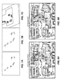
- a line drawing example of such a reference map 42 is shown in FIG. 4A showing travel paths, e.g. the roads in this particular reference map, in a geographic area. The travel paths are shown in shaded lines in FIG. 4B .
- the mapping information may be obtained on-line, e.g. via an Internet connection, and/or off-line, e.g. via storage media, e.g. electrical, magnetic or optical disc.
- This travel path metadata and its associated reference maps may be housed in the server 28. Alternatively, this travel path metadata and its associated reference maps may be housed in the processor 24.
- a plurality of digital images may be taken by the image capturing device 20.
- the images may then be transmitted to the processor 24 for processing.
- the processor 24 may be configured to separate the photographs into individual images 44a, 44b, 44c etc.
- the processor 24 may be configured to separate the video sequence into individual images 44a, 44b, 44c etc.
- the processor 24 may be configured to access the server 28 to obtain an appropriate reference map 42, see FIG. 4A , containing geo-registration information.
- the processor 24 may be configured to compare the images from the image capturing device 20 to the reference map 42.
- the processor 24 may then geo-register the images to the reference map using matching of image features and planar homography.
- the first image 44a may be manually registered to the reference map 42 by the user inputting the registration information into the processor 24 via the user interface 26.
- the processor 24 may be configured to register the first image 44a to the reference map 42 in an automated manner by using inputs such as GPS and/or inertial sensors built into the image capturing device 20.
- the processor 24 may be configured to use planar homography to align the images 44a, 44b, 44c etc. to the reference map 42.
- H 0,M is the homography which aligns the first image 44a to the reference map 42.
- subsequent images 44b, 44c ... are geo-registered as follows.
- I t is defined as the image captured image capturing device at time t
- I t + 1 is defined as the subsequent image.
- image to image registration is performed in a known manner by extracting scale-invariant feature transform (SIFT) descriptors, or other known descriptors, from the images in both images (the current image being analyzed and the previous image already analyzed).
- SIFT scale-invariant feature transform
- the above method can introduce small errors in each homography computation, which errors accumulate over time and can result in misaligned images after some time. These errors are mitigated by refining the image to image registration with an additional image to reference map registration. At time t, it is assumed that the image It to be geo-registered is within a small error bound. The geo-registration is refined by matching interest points in It and the reference map 42 via mutual information of the image patches.
- Mutual information is a measure of the information overlap between two signals, or how much knowledge of one signal can provide knowledge of second signal. Mutual information is robust and useful because it is only sensitive to whether one signal changes when the other signal does not, not to their relative values.
- FIGS. 4A-4D An example of a geo-registered video sequence can be seen in FIGS. 4A-4D.
- FIG. 4A shows the reference map 42.
- FIG. 4B shows the first image 44a registered to the reference map 42.
- FIGS. 4C and 4D show subsequent images 44b, 44c registered to the reference map 42.
- the travel paths are shown in shaded line using travel path metadata obtained from the reference map 42.
- the processor 24 may be configured to use the travel path metadata from the reference map 42 as additional context for detecting a moving object of interest 46, for example a vehicle, in the images 44a, 44b, 44c etc.
- the moving object detection is performed by the processor 24 by calculating differences in consecutive images, for example, 44a and 44b, after they have been geo-registered to the reference image 42 by using coarse background subtraction in a known manner.
- I t is defined as the reference image 42, then images I t-k , I t-(k-1) ,... I t-1 , I t+2 ,.... I t+k are registered using I t as the reference coordinate system.
- the processor 24 is configured to perform the thresholding operation on the accumulated difference image based upon the labeled map regions, resulting in segmented image regions that represent objects moving faster than a certain speed relative to the background.
- the threshold T By varying the threshold T, the sensitivity to motion can be made dependent on the labeled map region that contains the segmented image regions. For example, a lower sensitivity threshold is used for a candidate moving object in the travel path versus a candidate moving object outside of the travel path.
- the processor 24 may be configured to detect the segmented image regions as objects based upon the region size, shape and dynamic properties with variable decision threshold based upon the labeled map regions. Thereafter, the processor 24 may be configured to form tracks, for example by using a Kalman filter in a known manner, or another suitable known tracker. As a final step, the processor 24 may be configured to output the object detections and the tracks to the user.
- FIGS. 7A-7C An example of the moving object detection and tracking process is provided in FIGS. 7A-7C.
- FIG. 7A shows the accumulated difference image.
- FIG. 7B shows the segmented regions after processing the accumulated difference image of FIG. 7A , e.g. with thresholding and morphological operations. Such morphological operations are well-known in the art.
- FIG. 7C shows the object tracking results.
- Each tracked object of interest 46 may be represented by a fitted ellipse, e.g. an ellipse of a specific color.
- a history of previous locations of the tracked object of interest 46 may be shown as trailing dots of the same color.
- the processor 24 may be configured to use the travel path metadata to suppress false alarms for detections that are not on a travel path.
- the method performs the steps of FIG. 6B which uses travel path metadata to filter out false alarms and enhance missed detections.
- the false alarm rate is reduced by using only the travel path metadata (reducing search area) because the number of false alarms per image is approximately proportional to the search area. If the search area is reduced using travel path metadata, then the false alarm rate will decrease while the detection rate of a moving object will stay unchanged. If the sensitivity threshold is lowered, the detection rate of a moving object will increase and the false alarm rate will also increase from the value it was lowered to using the travel path metadata.
- the sensitivity threshold can be lowered so that the false alarm rate is unchanged from the rate without metadata. The detection rate will then be higher due to the lower sensitivity threshold value.
- the false alarm rate can be kept constant by lowering the sensitivity threshold and reducing the search area. In this method, the accumulated difference image is thresholded and converted to a binary image. If the search area is reduced, the false alarm rate is kept constant by lowering the sensitivity threshold.
- the user sets the sensitivity threshold T in the processor 24 for detection of an object of interest 46.
- the sensitivity threshold T may be set, for example, by the user setting a predetermined level of contrast in the images between the moving object and the structure that the moving object is on, or may be set, for example, by the user setting a predetermined pixel count for the a moving object.
- the sensitivity threshold T may be set lower in the regions where a travel path is located, which regions are known from the reference map 42, and higher in any non-travel path region.
- the processor 24 may be configured to recognize that a moving object is darker than the travel path or the buildings in the images, and/or the processor 24 may be configured to recognize that a moving object is lighter than the travel path in the images or the buildings.
- the processor 24 may be configured to recognize that a moving object has a higher pixel count than the travel path. If, however, the user sets the sensitivity threshold T too low (requiring a small amount of contrast or small difference in pixel count between the moving object and the structure that the moving object is on), this may result in an unacceptable number of false alarms, because many objects will meet this setting. If, however, the user sets the sensitivity threshold T too high (requiring a great amount of contrast or large difference in pixel count between the moving object and the structure that the moving object is on), this may result in missed detections because objects in the shadow of a building will not show a high level of contrast between the moving object and the travel path or a high difference in pixel count.
- travel path metadata is used by the processor 24 as context, false alarms in areas outside of the travel path are suppressed. At the same time, missed detections on the travel path are reduced because the lower sensitivity threshold is used in the moving object detection process in the travel path.
- a lower sensitivity threshold effectively boosts the sensitivity of the moving object detection process.
- the assumption is that the moving object of interest 46 to be detected is a vehicle which are typically on the travel path, and not typically off of the travel path.
- FIGS. 8A and 8B illustrate some of the difficulties that may be encountered when processing images 44a, 44b, 44c taken in an urban environment.
- the tall buildings and vegetation are not on the ground plane and therefore cannot be aligned using the planar homography.
- the squared difference operation can introduce false alarms and missed detections such as the ones seen in FIG. 8A .
- a false alarm may result from a moving object in the images which is not on the travel path.
- a missed detection may arise when a moving object of interest is in the shadow of a tall building and is not easily detected by the image capturing device 20 and processor 24.
- By using the travel path metadata as additional context, such false alarms and missed detection are mitigated by using the method in FIG. 6B .
- the travel path metadata may also be used to increase the sensitivity of the moving object detection process in areas inside the travel path. As seen in FIG. 8A , a moving vehicle is undetected in the shadow of the tall building. This is due to the low contrast of the image in that area. By lowering the sensitivity threshold of the detection process along in the regions where a travel path is located, this moving vehicle is detected.
- the processor 24 may be configured to track the location of the moving object of interest 46 over time. Alternatively, once a moving object of interest 46 is detected, the user may input instructions into the processor 26 via the user interface 26 to track that specific moving object of interest 46. The processor 24 may be configured to detect a moving object of interest 46 in the successive images 44a, 44b, 44c by appearance, location, velocity, etc.
- the detected moving object of interest 46 has precise geo-coordinates. This enables a user to easily detect and track the moving object of interest 46.
- the present invention can be used to detect and track multiple moving objects of interest in the images 44a, 44b, 44c. These multiple moving objects of interest may be on the same travel path in the images 44a, 44b, 44c. Alternatively, one or more of the multiple moving objects of interest may be one travel path in the images 44a, 44b, 44c, and another one or more of the multiple moving objects of interest may be a different travel path in the images 44a, 44b, 44c, etc.
Landscapes
- Engineering & Computer Science (AREA)
- Physics & Mathematics (AREA)
- General Physics & Mathematics (AREA)
- Theoretical Computer Science (AREA)
- Computer Vision & Pattern Recognition (AREA)
- Multimedia (AREA)
- Data Mining & Analysis (AREA)
- Aviation & Aerospace Engineering (AREA)
- Bioinformatics & Computational Biology (AREA)
- Bioinformatics & Cheminformatics (AREA)
- Artificial Intelligence (AREA)
- Evolutionary Biology (AREA)
- Evolutionary Computation (AREA)
- General Engineering & Computer Science (AREA)
- Life Sciences & Earth Sciences (AREA)
- Radar, Positioning & Navigation (AREA)
- Remote Sensing (AREA)
- Image Analysis (AREA)
- Image Processing (AREA)
- Traffic Control Systems (AREA)
Abstract
Description
- The present invention relates to real-time detection of a moving object of interest on a travel path, and reducing false alarms and missed detections. The present invention may also be used to track such a moving object in real-time.
- Prior art systems for detecting and tracking an object of interest travelling on path, such as a travel path, using video tracking are known. Many of these systems, however, are limited in their accuracy of detecting an object in real-time due to environmental artifacts and image quality resulting from lighting effects on the object of interest. As a result, current systems may not adequately track an object of interest in certain environments.
- A system and a method for real-time detection of a moving object on a travel path in a geographical area is provided. The system and method may also be used to track such a moving object in real-time. The system includes an image capturing device for capturing successive images of a geographical area, a geographical reference map comprising contextual information of the geographical area, and a processor configured to calculate differences between successive images to detect, in real-time, a moving object on the travel path. The method includes capturing successive images of the geographical area using the image capturing device, geo-registering at least some of the successive images relative to the geographical reference map, and calculating differences between the successive images to detect, in real-time, an object.
- Further, the disclosure comprises embodiments according to the following clauses:
- Clause 1. A method for real-time detection of an object comprising:
- capturing successive images of a geographical area containing at least one travel path using an image capturing device;
- geo-registering at least some of the successive images relative to a geographical reference map, the geographical reference map comprising contextual information of the geographical area; and
- calculating differences between the successive images to detect, in real-time, an object.
- Clause 2. The method of clause 1, wherein a first image of the successive images is manually geo-registered.
- Clause 3. The method of clause 1, further comprising obtaining images of the geographical area including a travel path.
- Clause 4. The method of clause 1, wherein the contextual information is travel path metadata.
- Clause 5. The method of clause 1, wherein the travel path is a road.
- Clause 6. The method of clause 1, wherein the image capturing device is positioned on an aerial vehicle.
- Clause 7. The method of clause 1, wherein the successive images are generated by capturing at least one video sequence of the geographical area, and further comprising separating the video sequence into the successive images.
- Clause 8. The method of clause 1, wherein planar homography is used to geo-register the successive images relative to one another on the reference map.
- Clause 9. The method of clause 1, further comprising using the contextual information to suppress false detections of moving objects outside of a travel path.
- Clause 10. The method of clause 1, further comprising using the contextual information to detect a moving object on a travel path.
- Clause 11. The method of clause 1, further comprising reducing errors in the geo-registration by adding an additional geo-registration of one of said successive images relative to the reference map.
- Clause 12. The method of clause 1, further including tracking the position of the moving object.
- Clause 13. A system for real-time detection of a moving object on a travel path in a geographical area comprising:
- an image capturing device for capturing successive images of a geographical area;
- a geographical reference map comprising contextual information of the geographical area; and
- a processor configured to calculate differences between successive images to detect, in real-time, a moving object on the travel path.
- Clause 14. The system of clause 13, wherein said image capturing device is a video camera.
- Clause 15. The system of clause 14, wherein said geographical reference map is a map that incorporates metadata.
- Clause 16. The system of clause 14, wherein said moving object is a vehicle and said travel path is a road.
- Clause 17. The system of clause 13, wherein the image capturing device is mounted on an aerial platform on an airborne vehicle.
- Clause 18. The system of clause 17, wherein the airborne vehicle is unmanned.
- Clause 19. The system of clause 13, wherein the geographical reference map is housed in a server remote from the processor.
-
Clause 20. The system of clause 13, wherein the processor is further configured to track the position of the moving object. - The scope of the present invention is defined solely by the appended claims and is not affected by the statements within this summary.
- The invention can be better understood with reference to the following drawings and description. The components in the figures are not necessarily to scale, emphasis instead being placed upon illustrating the principles of the invention.
-
FIG. 1 is a block diagram of the system which incorporates the features of the present invention; -
FIG. 2 is a block diagram of an image capturing device used in the system of the invention; -
FIG. 3 is a block diagram of a processor used in the system of the invention; -
FIGS. 4A-4D are line drawings showing a reference map and images taken by the image capturing device in the system of the invention; -
FIG. 5 are line drawings showing how the images are geo-registered to the reference map using planar homography in the system of the invention; -
FIG. 6A and6B are line drawings with associated flow charts showing the steps used in the present method; -
FIGS. 7A-7C show an example of a moving object detection of the present invention; -
FIG. 8A shows a moving object detection without using travel path metadata; and -
FIG. 8B shows a moving object detection using travel path metadata in accordance with the present invention. - While the invention may be susceptible to embodiment in different forms, there is shown in the drawings, and herein will be described in detail, a specific embodiment for detecting of a moving object of interest on a travel path using an image capturing device mounted on an aerial structure, such as an unmanned aerial vehicle (UAV), an aerial platform or a piloted vehicle, with the understanding that the present disclosure is to be considered an exemplification of the principles of the invention, and is not intended to limit the invention to that as illustrated and described herein. Therefore, unless otherwise noted, features disclosed herein may be combined together to form additional combinations that were not otherwise shown for purposes of brevity.
- A system and method for geo-registration and context aware moving object detection along a travel path, using images taken from an aerial location, to improve detection of a moving object on a travel path, and reducing false alarms and missed detections. The system and method may also be used to track such a moving object. The method may be performed in real-time. By combining geo-registration information with travel path metadata provided by a global mapping system, the accuracy of the system may be increased over the prior art.
- As illustrated by the block diagram in
FIG. 1 , the system comprises animage capturing device 20, such as a camera, for generating digital images of a geographic area that may contain at least one travel path, anaerial structure 22, such as a platform on unmanned aerial vehicle (UAV) or on a piloted vehicle, such as a helicopter, for mounting theimage capturing device 20, aprocessor 24 having software therein in communication with theimage capturing device 20 and capable of processing images from theimage capturing device 20, auser interface 26 in communication with theprocessor 24, and aserver 28 which houses the travel path metadata from the global mapping system and which is in communication with theprocessor 24. - The
image capturing device 20 is configured to capture digital images, such as photographs or a video of objects, such buildings, vegetation and vehicles, etc., disposed within the field of view of theimage capturing device 20. Theimage capturing device 20 is communicatively connected to theprocessor 24. Theimage capturing device 20 includes imagecapturing device optics 30, animage capturing unit 32 and acommunication interface 34. The imagecapturing device optics 30 comprises lenses and other optical components, and is communicatively coupled with theimage capturing unit 32. Theimage capturing unit 32 transfers images to thecommunication interface 34 which then transfers the images to theprocessor 24. - The
processor 24 and theserver 28 are coupled together to transmit information therebetween. The information is sent to and received from theserver 28, e.g., through a communication network such as a local area network, a wide area network, a wired network and/or a wireless network, etc. Theserver 28 can be on-board theaerial structure 22 or can be ground-based. - The
processor 24 can be on-board theaerial structure 22, or can be ground-based. If theprocessor 24 is on the ground, theimage capturing device 20 can send images to theprocessor 24 via wireless signals. Theprocessor 24 processes image information from theimage capturing device 20 and from theserver 28 and includes a central processing unit (CPU) or digital-signal processor (DSP) 36 andmemory 38. The CPU/DSP 36 is coupled to thememory 38 that includes random access memory (RAM) and read-only memory (ROM). Thememory 38 is non-transitory and stores machine-readable, machine-executable software code 40 containing instructions that are configured to, when executed, cause the CPU/DSP 36 to perform various functions described herein. Theprocessor 24 analyzes the information from theimage capturing unit 32 to produce image images which can be displayed on the display of theuser interface 26 and which can be printed using the printer of theuser interface 26 and analyzed by the user. - The
user interface 26 includes an input device, such as a keyboard, a display and speakers to provide visual and audio information to a user and to allow the user to input parameters into theprocessor 24. Theuser interface 26 may also include a printer for printing images captured by the system. - Global mapping systems, for example Google Maps, Bing Maps or any other suitable global mapping system that utilizes geo-positioning information, provides extensive travel path metadata for use by third parties. The travel path metadata provides, among other items, contextual information regarding the location of travel paths, such as roads, waterways and/or walking paths, and structures, such as buildings, vegetation and other potentially interfering objects, proximate to the travel paths.
- This travel path metadata may be provided as reference maps to third parties. A line drawing example of such a
reference map 42 is shown inFIG. 4A showing travel paths, e.g. the roads in this particular reference map, in a geographic area. The travel paths are shown in shaded lines inFIG. 4B . The mapping information may be obtained on-line, e.g. via an Internet connection, and/or off-line, e.g. via storage media, e.g. electrical, magnetic or optical disc. This travel path metadata and its associated reference maps may be housed in theserver 28. Alternatively, this travel path metadata and its associated reference maps may be housed in theprocessor 24. - A plurality of digital images, such as photographs or a video sequence, may be taken by the
image capturing device 20. The images may then be transmitted to theprocessor 24 for processing. In an embodiment where photographs are taken, theprocessor 24 may be configured to separate the photographs intoindividual images processor 24 may be configured to separate the video sequence intoindividual images processor 24 may be configured to access theserver 28 to obtain anappropriate reference map 42, seeFIG. 4A , containing geo-registration information. Theprocessor 24 may be configured to compare the images from theimage capturing device 20 to thereference map 42. Theprocessor 24 may then geo-register the images to the reference map using matching of image features and planar homography. - During the geo-registration process, the
first image 44a may be manually registered to thereference map 42 by the user inputting the registration information into theprocessor 24 via theuser interface 26. Alternatively, theprocessor 24 may be configured to register thefirst image 44a to thereference map 42 in an automated manner by using inputs such as GPS and/or inertial sensors built into theimage capturing device 20. In the present system and method, it is assumed that there is a dominant plane on theimages reference map 42, hence, theprocessor 24 may be configured to use planar homography to align theimages reference map 42. - In the following, H0,M is the homography which aligns the
first image 44a to thereference map 42. Given the registration of thefirst image 44a,subsequent images FIG. 6A , image to image registration is performed in a known manner by extracting scale-invariant feature transform (SIFT) descriptors, or other known descriptors, from the images in both images (the current image being analyzed and the previous image already analyzed). An initial set of correspondences is obtained by matching SIFT descriptors from the images in both images via their nearest neighbor in Euclidean space. These putative correspondences contain many incorrect matches, these are pruned via known methods, such as random sample consensus (RANSAC, described by Fischler, and Bolles, Comm. of the ACM, Vol. 24, pp. 381-395, 1981), or other method to estimate parameters of a mathematical model from a set of observed data which contains outliers, which also provides H t+1,t , which is the homography that aligns I t + 1 to It . As a result, the subsequent image I t+1 is geo-registered via the following product Ht + 1,t Ht,t-1 Ht-1t-2... H1,0H0,M or more simply
processor 24 may be configured to geo-register each successive image, or may be configured to geo-register predetermined ones of the images (e.g. some successive images are skipped). - The above method can introduce small errors in each homography computation, which errors accumulate over time and can result in misaligned images after some time. These errors are mitigated by refining the image to image registration with an additional image to reference map registration. At time t, it is assumed that the image It to be geo-registered is within a small error bound. The geo-registration is refined by matching interest points in It and the
reference map 42 via mutual information of the image patches. Mutual information is a measure of the information overlap between two signals, or how much knowledge of one signal can provide knowledge of second signal. Mutual information is robust and useful because it is only sensitive to whether one signal changes when the other signal does not, not to their relative values. Since thereference map 42 and the image being analyzed were taken at different times, there can be complicating factors such as different time of day, different weather conditions, etc, along with the fact that the image being analyzed may have been taken at a different angle than the image in thereference map 42. Mutual information helps to mitigate these complicating factors. As a result, the accumulation of errors and geo-registration "drift" are nullified. - An example of a geo-registered video sequence can be seen in
FIGS. 4A-4D. FIG. 4A shows thereference map 42.FIG. 4B shows thefirst image 44a registered to thereference map 42.FIGS. 4C and 4D showsubsequent images reference map 42. The travel paths are shown in shaded line using travel path metadata obtained from thereference map 42. - Once the images etc. are geo-registered, the
processor 24 may be configured to use the travel path metadata from thereference map 42 as additional context for detecting a moving object of interest 46, for example a vehicle, in theimages processor 24 by calculating differences in consecutive images, for example, 44a and 44b, after they have been geo-registered to thereference image 42 by using coarse background subtraction in a known manner. It is defined as thereference image 42, then images It-k, It-(k-1),... It-1, It+2,.... It+k are registered using It as the reference coordinate system. The pixel squared difference is then accumulated between thereference image 42 and allother images 
images reference image 42, stationary objects and the background will cancel each other out in the squared difference operation, whereas a moving object 46 will stand out. A sensitivity threshold T is applied to the accumulated difference image to produce a binary image B where
- In
FIG. 6B , once the difference image is calculated, theprocessor 24 is configured to perform the thresholding operation on the accumulated difference image based upon the labeled map regions, resulting in segmented image regions that represent objects moving faster than a certain speed relative to the background. By varying the threshold T, the sensitivity to motion can be made dependent on the labeled map region that contains the segmented image regions. For example, a lower sensitivity threshold is used for a candidate moving object in the travel path versus a candidate moving object outside of the travel path. Next, theprocessor 24 may be configured to detect the segmented image regions as objects based upon the region size, shape and dynamic properties with variable decision threshold based upon the labeled map regions. Thereafter, theprocessor 24 may be configured to form tracks, for example by using a Kalman filter in a known manner, or another suitable known tracker. As a final step, theprocessor 24 may be configured to output the object detections and the tracks to the user. - An example of the moving object detection and tracking process is provided in
FIGS. 7A-7C. FIG. 7A shows the accumulated difference image.FIG. 7B shows the segmented regions after processing the accumulated difference image ofFIG. 7A , e.g. with thresholding and morphological operations. Such morphological operations are well-known in the art.FIG. 7C shows the object tracking results. Each tracked object of interest 46 may be represented by a fitted ellipse, e.g. an ellipse of a specific color. A history of previous locations of the tracked object of interest 46 may be shown as trailing dots of the same color. - In addition, once the images etc. are geo-registered, the
processor 24 may be configured to use the travel path metadata to suppress false alarms for detections that are not on a travel path. Once a moving object of interest 46 is detected, the method performs the steps ofFIG. 6B which uses travel path metadata to filter out false alarms and enhance missed detections. The false alarm rate is reduced by using only the travel path metadata (reducing search area) because the number of false alarms per image is approximately proportional to the search area. If the search area is reduced using travel path metadata, then the false alarm rate will decrease while the detection rate of a moving object will stay unchanged. If the sensitivity threshold is lowered, the detection rate of a moving object will increase and the false alarm rate will also increase from the value it was lowered to using the travel path metadata. For example, the sensitivity threshold can be lowered so that the false alarm rate is unchanged from the rate without metadata. The detection rate will then be higher due to the lower sensitivity threshold value. The false alarm rate can be kept constant by lowering the sensitivity threshold and reducing the search area. In this method, the accumulated difference image is thresholded and converted to a binary image. If the search area is reduced, the false alarm rate is kept constant by lowering the sensitivity threshold. - The user sets the sensitivity threshold T in the
processor 24 for detection of an object of interest 46. The sensitivity threshold T may be set, for example, by the user setting a predetermined level of contrast in the images between the moving object and the structure that the moving object is on, or may be set, for example, by the user setting a predetermined pixel count for the a moving object. The sensitivity threshold T may be set lower in the regions where a travel path is located, which regions are known from thereference map 42, and higher in any non-travel path region. For example, theprocessor 24 may be configured to recognize that a moving object is darker than the travel path or the buildings in the images, and/or theprocessor 24 may be configured to recognize that a moving object is lighter than the travel path in the images or the buildings. Or, for example, theprocessor 24 may be configured to recognize that a moving object has a higher pixel count than the travel path. If, however, the user sets the sensitivity threshold T too low (requiring a small amount of contrast or small difference in pixel count between the moving object and the structure that the moving object is on), this may result in an unacceptable number of false alarms, because many objects will meet this setting. If, however, the user sets the sensitivity threshold T too high (requiring a great amount of contrast or large difference in pixel count between the moving object and the structure that the moving object is on), this may result in missed detections because objects in the shadow of a building will not show a high level of contrast between the moving object and the travel path or a high difference in pixel count. In the present invention, since travel path metadata is used by theprocessor 24 as context, false alarms in areas outside of the travel path are suppressed. At the same time, missed detections on the travel path are reduced because the lower sensitivity threshold is used in the moving object detection process in the travel path. A lower sensitivity threshold effectively boosts the sensitivity of the moving object detection process. In the examples shown inFIGS. 7A through 8B , the assumption is that the moving object of interest 46 to be detected is a vehicle which are typically on the travel path, and not typically off of the travel path. -
FIGS. 8A and 8B illustrate some of the difficulties that may be encountered when processingimages FIG. 8A . A false alarm may result from a moving object in the images which is not on the travel path. A missed detection may arise when a moving object of interest is in the shadow of a tall building and is not easily detected by theimage capturing device 20 andprocessor 24. By using the travel path metadata as additional context, such false alarms and missed detection are mitigated by using the method inFIG. 6B . - As described above, the travel path metadata may also be used to increase the sensitivity of the moving object detection process in areas inside the travel path. As seen in
FIG. 8A , a moving vehicle is undetected in the shadow of the tall building. This is due to the low contrast of the image in that area. By lowering the sensitivity threshold of the detection process along in the regions where a travel path is located, this moving vehicle is detected. - Once a moving object of interest 46 is detected, the
processor 24 may be configured to track the location of the moving object of interest 46 over time. Alternatively, once a moving object of interest 46 is detected, the user may input instructions into theprocessor 26 via theuser interface 26 to track that specific moving object of interest 46. Theprocessor 24 may be configured to detect a moving object of interest 46 in thesuccessive images - Since the
images - The present invention can be used to detect and track multiple moving objects of interest in the
images images images images - While particular aspects of the present subject matter described herein have been shown and described, it will be apparent to those skilled in the art that, based upon the teachings herein, changes and modifications may be made without departing from the subject matter described herein and its broad aspects and, therefore, the appended claims are to encompass within their scope all such changes and modifications as are within the true spirit and scope of the subject matter described herein. Furthermore, it is to be understood that the invention is defined by the appended claims. Accordingly, the invention is not to be restricted except in light of the appended claims and their equivalents.
Claims (20)
- A method for real-time detection of an object comprising:capturing successive images 44a, 44b, 44c of a geographical area containing at least one travel path using an image capturing device 20;geo-registering at least some of the successive images 44a, 44b, 44c relative to a geographical reference map 42, the geographical reference map 42 comprising contextual information of the geographical area; andcalculating differences between the successive images 44a, 44b, 44c to detect, in real-time, an object 46.
- The method of claim 1, wherein a first image 44a of the successive images 44a, 44b, 44c is manually geo-registered.
- The method of claim 1 or 2, further comprising obtaining images of the geographical area including a travel path.
- The method of claim 1, 2 or 3, wherein the contextual information is travel path metadata.
- The method of any of claims 1 to 4, wherein the travel path is a road.
- The method of any of claims 1 to 5, wherein the image capturing device 20 is positioned on an aerial vehicle.
- The method of any of claims 1 to 6, wherein the successive images 44a, 44b, 44c are generated by capturing at least one video sequence of the geographical area, and further comprising separating the video sequence into the successive images 44a, 44b 44c .
- The method of any of claims 1 to 7, wherein planar homography is used to geo-register the successive images 44a, 44b 44c relative to one another on the reference map 42.
- The method of any of claims 1 to 8, further comprising using the contextual information to suppress false detections of moving objects 46 outside of a travel path.
- The method of any of claims 1 to 9, further comprising using the contextual information to detect a moving object 46 on a travel path.
- The method of any of claims 1 to 10, further comprising reducing errors in the geo-registration by adding an additional geo-registration of one of said successive images 44a, 44b, 44c relative to the reference map 42.
- The method of any of claims 1 to 11, further including tracking the position of the moving object.
- A system for real-time detection of a moving object on a travel path in a geographical area comprising:an image capturing device 20 for capturing successive images 44a, 44b, 44c of a geographical area;a geographical reference map 42 comprising contextual information of the geographical area; anda processor 24 configured to calculate differences between successive images 44a, 44b, 44c to detect, in real-time, a moving object 46 on the travel path.
- The system of claim 13, wherein said image capturing device 20 is a video camera.
- The system of claim 13 or 14, wherein said geographical reference map 42 is a map that incorporates metadata.
- The system of claim 13, 14 or 15, wherein said moving object 46 is a vehicle and said travel path is a road.
- The system of claims 13 to 16, wherein the image capturing device 20 is mounted on an aerial platform on an airborne vehicle.
- The system of any of claims 13 to 17, wherein the airborne vehicle is unmanned.
- The system of any of claims 13 to 18, wherein the geographical reference map 42 is housed in a server 28 remote from the processor 24.
- The system of any of claims 13 to 19, wherein the processor 24 is further configured to track the position of the moving object 46.
Applications Claiming Priority (1)
| Application Number | Priority Date | Filing Date | Title |
|---|---|---|---|
| US14/247,398 US9734399B2 (en) | 2014-04-08 | 2014-04-08 | Context-aware object detection in aerial photographs/videos using travel path metadata |
Publications (2)
| Publication Number | Publication Date |
|---|---|
| EP2930686A1 true EP2930686A1 (en) | 2015-10-14 |
| EP2930686B1 EP2930686B1 (en) | 2020-09-02 |
Family
ID=52462808
Family Applications (1)
| Application Number | Title | Priority Date | Filing Date |
|---|---|---|---|
| EP15152754.6A Active EP2930686B1 (en) | 2014-04-08 | 2015-01-27 | Context-aware object detection in aerial photographs/videos using travel path metadata |
Country Status (6)
| Country | Link |
|---|---|
| US (1) | US9734399B2 (en) |
| EP (1) | EP2930686B1 (en) |
| JP (1) | JP6726932B2 (en) |
| KR (1) | KR102400452B1 (en) |
| CN (1) | CN104978390B (en) |
| BR (1) | BR102015003962B1 (en) |
Cited By (1)
| Publication number | Priority date | Publication date | Assignee | Title |
|---|---|---|---|---|
| WO2018136370A3 (en) * | 2017-01-21 | 2018-10-18 | Microsoft Technology Licensing, Llc | Low-cost, long-term aerial imagery |
Families Citing this family (18)
| Publication number | Priority date | Publication date | Assignee | Title |
|---|---|---|---|---|
| CN106851306B (en) | 2011-01-12 | 2020-08-04 | 太阳专利托管公司 | Moving picture decoding method and moving picture decoding device |
| WO2012117728A1 (en) | 2011-03-03 | 2012-09-07 | パナソニック株式会社 | Video image encoding method, video image decoding method, video image encoding device, video image decoding device, and video image encoding/decoding device |
| JP2013055569A (en) * | 2011-09-06 | 2013-03-21 | Sony Corp | Image capturing device, information processing device, control methods therefor, and programs therefor |
| US11080765B2 (en) * | 2013-03-14 | 2021-08-03 | Igor Gershteyn | Method and system for data structure creation, organization and searching using basic atomic units of information |
| AU2016350155B2 (en) * | 2015-11-08 | 2021-08-19 | Agrowing Ltd | A method for aerial imagery acquisition and analysis |
| US10248839B2 (en) * | 2015-11-30 | 2019-04-02 | Intel Corporation | Locating objects within depth images |
| EP3387506B1 (en) * | 2015-12-09 | 2021-01-13 | SZ DJI Technology Co., Ltd. | Systems and methods for auto-return |
| CN105512685B (en) * | 2015-12-10 | 2019-12-03 | 小米科技有限责任公司 | Object identification method and device |
| US10670418B2 (en) * | 2016-05-04 | 2020-06-02 | International Business Machines Corporation | Video based route recognition |
| US10054445B2 (en) * | 2016-05-16 | 2018-08-21 | Northrop Grumman Systems Corporation | Vision-aided aerial navigation |
| IL248749B (en) * | 2016-11-03 | 2019-08-29 | Dan El Eglick | System for a route overview using several sources of data |
| US10209089B2 (en) | 2017-04-03 | 2019-02-19 | Robert Bosch Gmbh | Automated image labeling for vehicles based on maps |
| CN108176049B (en) * | 2017-12-28 | 2021-05-25 | 珠海豹好玩科技有限公司 | Information prompting method, device, terminal and computer readable storage medium |
| US10445913B2 (en) * | 2018-03-05 | 2019-10-15 | Faro Technologies, Inc. | System and method of scanning and editing two dimensional floorplans |
| US11195324B1 (en) | 2018-08-14 | 2021-12-07 | Certainteed Llc | Systems and methods for visualization of building structures |
| CN110349173B (en) * | 2019-07-15 | 2020-07-24 | 长光卫星技术有限公司 | Ground feature change monitoring method based on high-resolution remote sensing image |
| US11200671B2 (en) * | 2019-12-31 | 2021-12-14 | International Business Machines Corporation | Reference image guided object detection in medical image processing |
| CN111619584B (en) * | 2020-05-27 | 2021-09-21 | 北京经纬恒润科技股份有限公司 | State supervision method and device for unmanned automobile |
Family Cites Families (9)
| Publication number | Priority date | Publication date | Assignee | Title |
|---|---|---|---|---|
| US7424133B2 (en) * | 2002-11-08 | 2008-09-09 | Pictometry International Corporation | Method and apparatus for capturing, geolocating and measuring oblique images |
| KR100489890B1 (en) * | 2002-11-22 | 2005-05-17 | 한국전자통신연구원 | Apparatus and Method to Provide Stereo Video or/and Detailed Information of Geographic Objects |
| WO2009158494A1 (en) * | 2008-06-26 | 2009-12-30 | Lynntech, Inc. | Method of searching for a thermal target |
| WO2011133845A2 (en) * | 2010-04-22 | 2011-10-27 | Bae Systems Information And Electronic Systems Integration Inc. | Situational awareness integrated network and system for tactical information and communications |
| US10645344B2 (en) | 2010-09-10 | 2020-05-05 | Avigilion Analytics Corporation | Video system with intelligent visual display |
| US9746988B2 (en) * | 2011-05-23 | 2017-08-29 | The Boeing Company | Multi-sensor surveillance system with a common operating picture |
| US20130021475A1 (en) * | 2011-07-21 | 2013-01-24 | Canant Ross L | Systems and methods for sensor control |
| US8958945B2 (en) * | 2012-02-07 | 2015-02-17 | Ge Aviation Systems Llc | System and methods for maintaining and operating an aircraft |
| US9904852B2 (en) * | 2013-05-23 | 2018-02-27 | Sri International | Real-time object detection, tracking and occlusion reasoning |
-
2014
- 2014-04-08 US US14/247,398 patent/US9734399B2/en active Active
-
2015
- 2015-01-27 EP EP15152754.6A patent/EP2930686B1/en active Active
- 2015-02-24 BR BR102015003962-0A patent/BR102015003962B1/en active IP Right Grant
- 2015-03-25 JP JP2015062049A patent/JP6726932B2/en active Active
- 2015-03-27 KR KR1020150043202A patent/KR102400452B1/en active IP Right Grant
- 2015-04-07 CN CN201510161125.7A patent/CN104978390B/en active Active
Non-Patent Citations (5)
| Title |
|---|
| DEEPAK KHOSLA ET AL: "A neuromorphic system for object detection and classification", PROCEEDINGS OF SPIE, vol. 8745, 23 May 2013 (2013-05-23), pages 87450X, XP055204349, ISSN: 0277-786X, DOI: 10.1117/12.2016038 * |
| FISCHLER; BOLLES, COMM. OF THE ACM, vol. 24, 1981, pages 381 - 395 |
| JIANGJIAN XIAO ET AL: "Vehicle detection and tracking in wide field-of-view aerial video", 2010 IEEE CONFERENCE ON COMPUTER VISION AND PATTERN RECOGNITION (CVPR), 13-18 JUNE 2010, SAN FRANCISCO, CA, USA, IEEE, PISCATAWAY, NJ, USA, 13 June 2010 (2010-06-13), pages 679 - 684, XP031725976, ISBN: 978-1-4244-6984-0 * |
| LI JING ET AL: "Moving Vehicle Detection in Dynamic Background from Airborne Monocular Camera", 2013 5TH INTERNATIONAL CONFERENCE ON INTELLIGENT HUMAN-MACHINE SYSTEMS AND CYBERNETICS, IEEE, vol. 1, 26 August 2013 (2013-08-26), pages 560 - 563, XP032515700, ISBN: 978-0-7695-5011-4, [retrieved on 20131021], DOI: 10.1109/IHMSC.2013.139 * |
| SHIH-MING HUANG ET AL: "Image registration among UAV image sequence and Google satellite image under quality mismatch", ITS TELECOMMUNICATIONS (ITST), 2012 12TH INTERNATIONAL CONFERENCE ON, IEEE, 5 November 2012 (2012-11-05), pages 311 - 315, XP032327808, ISBN: 978-1-4673-3071-8, DOI: 10.1109/ITST.2012.6425189 * |
Cited By (3)
| Publication number | Priority date | Publication date | Assignee | Title |
|---|---|---|---|---|
| WO2018136370A3 (en) * | 2017-01-21 | 2018-10-18 | Microsoft Technology Licensing, Llc | Low-cost, long-term aerial imagery |
| CN110192235A (en) * | 2017-01-21 | 2019-08-30 | 微软技术许可有限责任公司 | The long-term air-borne imagery of low cost |
| US10560666B2 (en) | 2017-01-21 | 2020-02-11 | Microsoft Technology Licensing, Llc | Low-cost, long-term aerial imagery |
Also Published As
| Publication number | Publication date |
|---|---|
| KR20150116777A (en) | 2015-10-16 |
| BR102015003962A2 (en) | 2016-07-26 |
| KR102400452B1 (en) | 2022-05-19 |
| EP2930686B1 (en) | 2020-09-02 |
| US9734399B2 (en) | 2017-08-15 |
| CN104978390B (en) | 2020-11-03 |
| CN104978390A (en) | 2015-10-14 |
| JP6726932B2 (en) | 2020-07-22 |
| US20150286868A1 (en) | 2015-10-08 |
| JP2015201183A (en) | 2015-11-12 |
| BR102015003962B1 (en) | 2021-06-01 |
Similar Documents
| Publication | Publication Date | Title |
|---|---|---|
| US9734399B2 (en) | Context-aware object detection in aerial photographs/videos using travel path metadata | |
| US11579623B2 (en) | Mobile robot system and method for generating map data using straight lines extracted from visual images | |
| Ahmadi et al. | Moving vehicle detection, tracking and traffic parameter estimation from a satellite video: A perspective on a smarter city | |
| Guido et al. | Evaluating the accuracy of vehicle tracking data obtained from Unmanned Aerial Vehicles | |
| Kang et al. | Pothole detection system using 2D LiDAR and camera | |
| US9760996B2 (en) | Non-rigid registration for large-scale space-time 3D point cloud alignment | |
| JP6713368B2 (en) | Information processing device, display device, information processing method, and program | |
| US9846812B2 (en) | Image recognition system for a vehicle and corresponding method | |
| WO2018177026A1 (en) | Device and method for determining road edge | |
| US10970871B2 (en) | Estimating two-dimensional object bounding box information based on bird's-eye view point cloud | |
| US20180158235A1 (en) | Method and apparatus for generating a cleaned object model for an object in a mapping database | |
| US11371851B2 (en) | Method and system for determining landmarks in an environment of a vehicle | |
| US11361457B2 (en) | Annotation cross-labeling for autonomous control systems | |
| KR101261409B1 (en) | System for recognizing road markings of image | |
| US11430199B2 (en) | Feature recognition assisted super-resolution method | |
| JP6647171B2 (en) | Information processing apparatus, information processing method, and program | |
| JP2018017102A (en) | Information processing apparatus, information processing method, and program | |
| JP2018017103A (en) | Information processing apparatus, information processing method, and program | |
| Kumar et al. | Vehicle speed detection using corner detection | |
| CN114419165B (en) | Camera external parameter correction method, camera external parameter correction device, electronic equipment and storage medium | |
| Jing et al. | Efficient point cloud corrections for mobile monitoring applications using road/rail-side infrastructure | |
| Mukhija et al. | Outdoor intersection detection for autonomous exploration | |
| CN103093481B (en) | A kind of based on moving target detecting method under the static background of watershed segmentation | |
| JP2022547580A (en) | Improved navigation and positioning using surface-seeking radar and deep learning | |
| Marques et al. | An evaluation of machine learning methods for speed-bump detection on a GoPro dataset |
Legal Events
| Date | Code | Title | Description |
|---|---|---|---|
| PUAI | Public reference made under article 153(3) epc to a published international application that has entered the european phase |
Free format text: ORIGINAL CODE: 0009012 |
|
| AK | Designated contracting states |
Kind code of ref document: A1 Designated state(s): AL AT BE BG CH CY CZ DE DK EE ES FI FR GB GR HR HU IE IS IT LI LT LU LV MC MK MT NL NO PL PT RO RS SE SI SK SM TR |
|
| AX | Request for extension of the european patent |
Extension state: BA ME |
|
| 17P | Request for examination filed |
Effective date: 20160413 |
|
| RBV | Designated contracting states (corrected) |
Designated state(s): AL AT BE BG CH CY CZ DE DK EE ES FI FR GB GR HR HU IE IS IT LI LT LU LV MC MK MT NL NO PL PT RO RS SE SI SK SM TR |
|
| STAA | Information on the status of an ep patent application or granted ep patent |
Free format text: STATUS: REQUEST FOR EXAMINATION WAS MADE |
|
| R17P | Request for examination filed (corrected) |
Effective date: 20160413 |
|
| STAA | Information on the status of an ep patent application or granted ep patent |
Free format text: STATUS: EXAMINATION IS IN PROGRESS |
|
| 17Q | First examination report despatched |
Effective date: 20180801 |
|
| REG | Reference to a national code |
Ref country code: DE Ref legal event code: R079 Ref document number: 602015058231 Country of ref document: DE Free format text: PREVIOUS MAIN CLASS: G06T0007000000 Ipc: G06T0007136000 |
|
| RIC1 | Information provided on ipc code assigned before grant |
Ipc: G06T 7/194 20170101ALI20200206BHEP Ipc: G06T 7/38 20170101ALI20200206BHEP Ipc: G06T 7/136 20170101AFI20200206BHEP |
|
| GRAP | Despatch of communication of intention to grant a patent |
Free format text: ORIGINAL CODE: EPIDOSNIGR1 |
|
| STAA | Information on the status of an ep patent application or granted ep patent |
Free format text: STATUS: GRANT OF PATENT IS INTENDED |
|
| INTG | Intention to grant announced |
Effective date: 20200318 |
|
| GRAS | Grant fee paid |
Free format text: ORIGINAL CODE: EPIDOSNIGR3 |
|
| GRAA | (expected) grant |
Free format text: ORIGINAL CODE: 0009210 |
|
| STAA | Information on the status of an ep patent application or granted ep patent |
Free format text: STATUS: THE PATENT HAS BEEN GRANTED |
|
| AK | Designated contracting states |
Kind code of ref document: B1 Designated state(s): AL AT BE BG CH CY CZ DE DK EE ES FI FR GB GR HR HU IE IS IT LI LT LU LV MC MK MT NL NO PL PT RO RS SE SI SK SM TR |
|
| REG | Reference to a national code |
Ref country code: GB Ref legal event code: FG4D |
|
| REG | Reference to a national code |
Ref country code: AT Ref legal event code: REF Ref document number: 1309711 Country of ref document: AT Kind code of ref document: T Effective date: 20200915 Ref country code: CH Ref legal event code: EP |
|
| REG | Reference to a national code |
Ref country code: DE Ref legal event code: R096 Ref document number: 602015058231 Country of ref document: DE |
|
| REG | Reference to a national code |
Ref country code: IE Ref legal event code: FG4D |
|
| REG | Reference to a national code |
Ref country code: LT Ref legal event code: MG4D |
|
| PG25 | Lapsed in a contracting state [announced via postgrant information from national office to epo] |
Ref country code: BG Free format text: LAPSE BECAUSE OF FAILURE TO SUBMIT A TRANSLATION OF THE DESCRIPTION OR TO PAY THE FEE WITHIN THE PRESCRIBED TIME-LIMIT Effective date: 20201202 Ref country code: NO Free format text: LAPSE BECAUSE OF FAILURE TO SUBMIT A TRANSLATION OF THE DESCRIPTION OR TO PAY THE FEE WITHIN THE PRESCRIBED TIME-LIMIT Effective date: 20201202 Ref country code: GR Free format text: LAPSE BECAUSE OF FAILURE TO SUBMIT A TRANSLATION OF THE DESCRIPTION OR TO PAY THE FEE WITHIN THE PRESCRIBED TIME-LIMIT Effective date: 20201203 Ref country code: SE Free format text: LAPSE BECAUSE OF FAILURE TO SUBMIT A TRANSLATION OF THE DESCRIPTION OR TO PAY THE FEE WITHIN THE PRESCRIBED TIME-LIMIT Effective date: 20200902 Ref country code: HR Free format text: LAPSE BECAUSE OF FAILURE TO SUBMIT A TRANSLATION OF THE DESCRIPTION OR TO PAY THE FEE WITHIN THE PRESCRIBED TIME-LIMIT Effective date: 20200902 Ref country code: FI Free format text: LAPSE BECAUSE OF FAILURE TO SUBMIT A TRANSLATION OF THE DESCRIPTION OR TO PAY THE FEE WITHIN THE PRESCRIBED TIME-LIMIT Effective date: 20200902 Ref country code: LT Free format text: LAPSE BECAUSE OF FAILURE TO SUBMIT A TRANSLATION OF THE DESCRIPTION OR TO PAY THE FEE WITHIN THE PRESCRIBED TIME-LIMIT Effective date: 20200902 |
|
| REG | Reference to a national code |
Ref country code: NL Ref legal event code: MP Effective date: 20200902 |
|
| REG | Reference to a national code |
Ref country code: AT Ref legal event code: MK05 Ref document number: 1309711 Country of ref document: AT Kind code of ref document: T Effective date: 20200902 |
|
| PG25 | Lapsed in a contracting state [announced via postgrant information from national office to epo] |
Ref country code: LV Free format text: LAPSE BECAUSE OF FAILURE TO SUBMIT A TRANSLATION OF THE DESCRIPTION OR TO PAY THE FEE WITHIN THE PRESCRIBED TIME-LIMIT Effective date: 20200902 Ref country code: RS Free format text: LAPSE BECAUSE OF FAILURE TO SUBMIT A TRANSLATION OF THE DESCRIPTION OR TO PAY THE FEE WITHIN THE PRESCRIBED TIME-LIMIT Effective date: 20200902 Ref country code: PL Free format text: LAPSE BECAUSE OF FAILURE TO SUBMIT A TRANSLATION OF THE DESCRIPTION OR TO PAY THE FEE WITHIN THE PRESCRIBED TIME-LIMIT Effective date: 20200902 |
|
| PG25 | Lapsed in a contracting state [announced via postgrant information from national office to epo] |
Ref country code: RO Free format text: LAPSE BECAUSE OF FAILURE TO SUBMIT A TRANSLATION OF THE DESCRIPTION OR TO PAY THE FEE WITHIN THE PRESCRIBED TIME-LIMIT Effective date: 20200902 Ref country code: SM Free format text: LAPSE BECAUSE OF FAILURE TO SUBMIT A TRANSLATION OF THE DESCRIPTION OR TO PAY THE FEE WITHIN THE PRESCRIBED TIME-LIMIT Effective date: 20200902 Ref country code: EE Free format text: LAPSE BECAUSE OF FAILURE TO SUBMIT A TRANSLATION OF THE DESCRIPTION OR TO PAY THE FEE WITHIN THE PRESCRIBED TIME-LIMIT Effective date: 20200902 Ref country code: PT Free format text: LAPSE BECAUSE OF FAILURE TO SUBMIT A TRANSLATION OF THE DESCRIPTION OR TO PAY THE FEE WITHIN THE PRESCRIBED TIME-LIMIT Effective date: 20210104 Ref country code: NL Free format text: LAPSE BECAUSE OF FAILURE TO SUBMIT A TRANSLATION OF THE DESCRIPTION OR TO PAY THE FEE WITHIN THE PRESCRIBED TIME-LIMIT Effective date: 20200902 Ref country code: CZ Free format text: LAPSE BECAUSE OF FAILURE TO SUBMIT A TRANSLATION OF THE DESCRIPTION OR TO PAY THE FEE WITHIN THE PRESCRIBED TIME-LIMIT Effective date: 20200902 |
|
| PG25 | Lapsed in a contracting state [announced via postgrant information from national office to epo] |
Ref country code: AL Free format text: LAPSE BECAUSE OF FAILURE TO SUBMIT A TRANSLATION OF THE DESCRIPTION OR TO PAY THE FEE WITHIN THE PRESCRIBED TIME-LIMIT Effective date: 20200902 Ref country code: AT Free format text: LAPSE BECAUSE OF FAILURE TO SUBMIT A TRANSLATION OF THE DESCRIPTION OR TO PAY THE FEE WITHIN THE PRESCRIBED TIME-LIMIT Effective date: 20200902 Ref country code: ES Free format text: LAPSE BECAUSE OF FAILURE TO SUBMIT A TRANSLATION OF THE DESCRIPTION OR TO PAY THE FEE WITHIN THE PRESCRIBED TIME-LIMIT Effective date: 20200902 Ref country code: IS Free format text: LAPSE BECAUSE OF FAILURE TO SUBMIT A TRANSLATION OF THE DESCRIPTION OR TO PAY THE FEE WITHIN THE PRESCRIBED TIME-LIMIT Effective date: 20210102 |
|
| REG | Reference to a national code |
Ref country code: DE Ref legal event code: R097 Ref document number: 602015058231 Country of ref document: DE |
|
| PG25 | Lapsed in a contracting state [announced via postgrant information from national office to epo] |
Ref country code: SK Free format text: LAPSE BECAUSE OF FAILURE TO SUBMIT A TRANSLATION OF THE DESCRIPTION OR TO PAY THE FEE WITHIN THE PRESCRIBED TIME-LIMIT Effective date: 20200902 |
|
| PLBE | No opposition filed within time limit |
Free format text: ORIGINAL CODE: 0009261 |
|
| STAA | Information on the status of an ep patent application or granted ep patent |
Free format text: STATUS: NO OPPOSITION FILED WITHIN TIME LIMIT |
|
| 26N | No opposition filed |
Effective date: 20210603 |
|
| PG25 | Lapsed in a contracting state [announced via postgrant information from national office to epo] |
Ref country code: SI Free format text: LAPSE BECAUSE OF FAILURE TO SUBMIT A TRANSLATION OF THE DESCRIPTION OR TO PAY THE FEE WITHIN THE PRESCRIBED TIME-LIMIT Effective date: 20200902 Ref country code: DK Free format text: LAPSE BECAUSE OF FAILURE TO SUBMIT A TRANSLATION OF THE DESCRIPTION OR TO PAY THE FEE WITHIN THE PRESCRIBED TIME-LIMIT Effective date: 20200902 Ref country code: MC Free format text: LAPSE BECAUSE OF FAILURE TO SUBMIT A TRANSLATION OF THE DESCRIPTION OR TO PAY THE FEE WITHIN THE PRESCRIBED TIME-LIMIT Effective date: 20200902 |
|
| REG | Reference to a national code |
Ref country code: CH Ref legal event code: PL |
|
| PG25 | Lapsed in a contracting state [announced via postgrant information from national office to epo] |
Ref country code: LU Free format text: LAPSE BECAUSE OF NON-PAYMENT OF DUE FEES Effective date: 20210127 |
|
| REG | Reference to a national code |
Ref country code: BE Ref legal event code: MM Effective date: 20210131 |
|
| PG25 | Lapsed in a contracting state [announced via postgrant information from national office to epo] |
Ref country code: IT Free format text: LAPSE BECAUSE OF FAILURE TO SUBMIT A TRANSLATION OF THE DESCRIPTION OR TO PAY THE FEE WITHIN THE PRESCRIBED TIME-LIMIT Effective date: 20200902 |
|
| PG25 | Lapsed in a contracting state [announced via postgrant information from national office to epo] |
Ref country code: LI Free format text: LAPSE BECAUSE OF NON-PAYMENT OF DUE FEES Effective date: 20210131 Ref country code: CH Free format text: LAPSE BECAUSE OF NON-PAYMENT OF DUE FEES Effective date: 20210131 |
|
| PG25 | Lapsed in a contracting state [announced via postgrant information from national office to epo] |
Ref country code: IE Free format text: LAPSE BECAUSE OF NON-PAYMENT OF DUE FEES Effective date: 20210127 |
|
| PG25 | Lapsed in a contracting state [announced via postgrant information from national office to epo] |
Ref country code: BE Free format text: LAPSE BECAUSE OF NON-PAYMENT OF DUE FEES Effective date: 20210131 |
|
| PGFP | Annual fee paid to national office [announced via postgrant information from national office to epo] |
Ref country code: FR Payment date: 20230125 Year of fee payment: 9 |
|
| PG25 | Lapsed in a contracting state [announced via postgrant information from national office to epo] |
Ref country code: HU Free format text: LAPSE BECAUSE OF FAILURE TO SUBMIT A TRANSLATION OF THE DESCRIPTION OR TO PAY THE FEE WITHIN THE PRESCRIBED TIME-LIMIT; INVALID AB INITIO Effective date: 20150127 |
|
| P01 | Opt-out of the competence of the unified patent court (upc) registered |
Effective date: 20230516 |
|
| PG25 | Lapsed in a contracting state [announced via postgrant information from national office to epo] |
Ref country code: CY Free format text: LAPSE BECAUSE OF FAILURE TO SUBMIT A TRANSLATION OF THE DESCRIPTION OR TO PAY THE FEE WITHIN THE PRESCRIBED TIME-LIMIT Effective date: 20200902 |
|
| PG25 | Lapsed in a contracting state [announced via postgrant information from national office to epo] |
Ref country code: MK Free format text: LAPSE BECAUSE OF FAILURE TO SUBMIT A TRANSLATION OF THE DESCRIPTION OR TO PAY THE FEE WITHIN THE PRESCRIBED TIME-LIMIT Effective date: 20200902 |
|
| PGFP | Annual fee paid to national office [announced via postgrant information from national office to epo] |
Ref country code: DE Payment date: 20240129 Year of fee payment: 10 Ref country code: GB Payment date: 20240129 Year of fee payment: 10 |