EP2924377B1 - Refrigerator - Google Patents
Refrigerator Download PDFInfo
- Publication number
- EP2924377B1 EP2924377B1 EP15158851.4A EP15158851A EP2924377B1 EP 2924377 B1 EP2924377 B1 EP 2924377B1 EP 15158851 A EP15158851 A EP 15158851A EP 2924377 B1 EP2924377 B1 EP 2924377B1
- Authority
- EP
- European Patent Office
- Prior art keywords
- guide
- shelf
- button
- pair
- lever
- Prior art date
- Legal status (The legal status is an assumption and is not a legal conclusion. Google has not performed a legal analysis and makes no representation as to the accuracy of the status listed.)
- Active
Links
- 230000000712 assembly Effects 0.000 claims description 27
- 238000000429 assembly Methods 0.000 claims description 27
- 230000002093 peripheral effect Effects 0.000 claims description 15
- 239000012780 transparent material Substances 0.000 claims description 3
- 238000007710 freezing Methods 0.000 description 14
- 230000008014 freezing Effects 0.000 description 14
- 235000013305 food Nutrition 0.000 description 11
- 238000012986 modification Methods 0.000 description 4
- 230000004048 modification Effects 0.000 description 4
- 238000003825 pressing Methods 0.000 description 4
- 238000001816 cooling Methods 0.000 description 3
- 230000000694 effects Effects 0.000 description 3
- 239000000463 material Substances 0.000 description 3
- 235000013361 beverage Nutrition 0.000 description 2
- 230000008878 coupling Effects 0.000 description 2
- 238000010168 coupling process Methods 0.000 description 2
- 238000005859 coupling reaction Methods 0.000 description 2
- 238000004519 manufacturing process Methods 0.000 description 2
- 229920003023 plastic Polymers 0.000 description 2
- 238000013459 approach Methods 0.000 description 1
- 230000015572 biosynthetic process Effects 0.000 description 1
- 230000000881 depressing effect Effects 0.000 description 1
- 238000007599 discharging Methods 0.000 description 1
- 239000011521 glass Substances 0.000 description 1
- 235000021109 kimchi Nutrition 0.000 description 1
- 238000000465 moulding Methods 0.000 description 1
- 238000005057 refrigeration Methods 0.000 description 1
- 235000013311 vegetables Nutrition 0.000 description 1
Images


Classifications
-
- F—MECHANICAL ENGINEERING; LIGHTING; HEATING; WEAPONS; BLASTING
- F25—REFRIGERATION OR COOLING; COMBINED HEATING AND REFRIGERATION SYSTEMS; HEAT PUMP SYSTEMS; MANUFACTURE OR STORAGE OF ICE; LIQUEFACTION SOLIDIFICATION OF GASES
- F25D—REFRIGERATORS; COLD ROOMS; ICE-BOXES; COOLING OR FREEZING APPARATUS NOT OTHERWISE PROVIDED FOR
- F25D25/00—Charging, supporting, and discharging the articles to be cooled
- F25D25/02—Charging, supporting, and discharging the articles to be cooled by shelves
- F25D25/024—Slidable shelves
-
- F—MECHANICAL ENGINEERING; LIGHTING; HEATING; WEAPONS; BLASTING
- F25—REFRIGERATION OR COOLING; COMBINED HEATING AND REFRIGERATION SYSTEMS; HEAT PUMP SYSTEMS; MANUFACTURE OR STORAGE OF ICE; LIQUEFACTION SOLIDIFICATION OF GASES
- F25D—REFRIGERATORS; COLD ROOMS; ICE-BOXES; COOLING OR FREEZING APPARATUS NOT OTHERWISE PROVIDED FOR
- F25D23/00—General constructional features
-
- A—HUMAN NECESSITIES
- A47—FURNITURE; DOMESTIC ARTICLES OR APPLIANCES; COFFEE MILLS; SPICE MILLS; SUCTION CLEANERS IN GENERAL
- A47B—TABLES; DESKS; OFFICE FURNITURE; CABINETS; DRAWERS; GENERAL DETAILS OF FURNITURE
- A47B57/00—Cabinets, racks or shelf units, characterised by features for adjusting shelves or partitions
- A47B57/06—Cabinets, racks or shelf units, characterised by features for adjusting shelves or partitions with means for adjusting the height of the shelves
- A47B57/08—Cabinets, racks or shelf units, characterised by features for adjusting shelves or partitions with means for adjusting the height of the shelves consisting of grooved or notched ledges, uprights or side walls
-
- F—MECHANICAL ENGINEERING; LIGHTING; HEATING; WEAPONS; BLASTING
- F25—REFRIGERATION OR COOLING; COMBINED HEATING AND REFRIGERATION SYSTEMS; HEAT PUMP SYSTEMS; MANUFACTURE OR STORAGE OF ICE; LIQUEFACTION SOLIDIFICATION OF GASES
- F25D—REFRIGERATORS; COLD ROOMS; ICE-BOXES; COOLING OR FREEZING APPARATUS NOT OTHERWISE PROVIDED FOR
- F25D25/00—Charging, supporting, and discharging the articles to be cooled
- F25D25/04—Charging, supporting, and discharging the articles to be cooled by conveyors
Definitions
- the present disclosure relates to a refrigerator.
- a refrigerator is an appliance for storing food, etc. within a storage chamber in a frozen or refrigerated state by discharging, into the storage chamber, cold air generated through a refrigeration cycle constituted by a compressor, a condenser, an expansion valve, an evaporator, etc.
- a refrigerator generally includes a freezing compartment for storing food or beverages in a frozen state, and a refrigerating compartment for storing food or beverages at low temperature.
- a Kimchi refrigerator which stores food such as Kimchi or vegetables in a fresh state, is another form of refrigerator.
- At least one of plural doors installed at a refrigerator is connected to one side of a body by a hinge, to open or close a front side of the body through pivotal movement thereof.
- a drawer type door may also be employed.
- the drawer type door includes a drawer, and a door mounted to a front side of the drawer, to be withdrawn or retracted in a forward or rearward direction, together with the drawer.
- storage compartments of a refrigerator namely, freezing and refrigerating compartments
- a plurality of shelves to vertically divide the freezing and refrigerating compartments into sections, in order to store food articles having various sizes and to enhance space utilization. Since food articles to be placed on such shelves may have various sizes, the shelves are separably mounted at different levels in the freezing and refrigerating compartments while being movable to adjust mounting levels thereof.
- Mounting of the shelves may be achieved by slidably mounting the shelves to a plurality of support ribs formed at left and right surfaces of the refrigerating and freezing compartments, or coupling a pair of cantilevers coupled to each shelf, and then mounting the cantilevers to mounting rails each formed with a plurality of vertically arranged holes.
- Level adjustment of shelves may be difficult and troublesome because, when it is desired to adjust mounting level of a shelf, the user has to separate the shelf from the support ribs or mounting rails after completely removing food articles from the shelf, and then to mount the separated shelf to another level.
- the applicant proposed a structure capable of adjusting the level of a shelf while food is placed thereon, as disclosed in Korean Unexamined Patent Publication No. 10-2006-0040290 .
- the disclosed structure has a problem in that, when it is desired to adjust the level of a shelf, the user has to move the shelf along an inclined guide slot in forward and rearward directions by a long distance. Furthermore, the shelf should be moved between an initial position and a final position by a considerable distance.
- the shelf may be moved to a lower position thereof along the guide slot.
- DE 102010030580 (A1 ) discloses an apparatus with a door arranged in an inner space of the apparatus. Two cams are provided at inside walls of the apparatus. Cooling containers are connected to a stand and the cams. A guide is placed at a lateral holding member and integrated to side walls of the cooling containers. The lateral holding member is placed on an inner side of a frame of a tray plate. The cams are inserted into a receiving opening of the guide.
- the guide is selected from a group consisting of an arc shaped guide and a C-shaped/S-shaped guide.
- EP2392878 discloses a directing element for household goods comprising a carrier which has at least one moving element thereon.
- a directing element is fixed to at least one inner walls of its internal part, and adjusts the height of the carrier by means of the moving element moving therein; the directing element comprises at least one upper channel inclined upwards and at least one lower channel inclined downwards in which the moving element moves, and at least one joint area where one each end of said channels meet and at least one curve located on at least one of the said channels, in which the moving element is seated.
- DE102011075102 (A1 ) discloses a refrigerator having an inner container provided with inner wall that limits a cooling space.
- a holding device has a holding section that is connected with the inner container and another holding section that is connected with a shelf base.
- the former holding section has two grooves arranged side by side at the same height.
- Each groove has locking position bays, which are arranged one above another.
- the locking positions bays are connected with each other by a groove channel.
- the latter holding section has holding projections for engaging in the grooves.
- KR950002348 (Y1 ) discloses a device for controlling shelf height of a refrigerator.
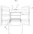
- FIG. 1 is a perspective view illustrating a bottom freezer type refrigerator equipped with a shelf assembly in accordance with the present disclosure.
- the refrigerator includes a cabinet 10 defined with a storage chamber therein, and a shelf assembly 100 mounted in the storage chamber, to be vertically movable.
- the illustrated refrigerator is a bottom freezer type refrigerator in which a refrigerating compartment 20 is provided at a top side of the cabinet 10, and a freezing compartment is provided at a bottom side of the cabinet 10.
- a refrigerating compartment 20 is provided at a top side of the cabinet 10
- a freezing compartment is provided at a bottom side of the cabinet 10.
- the present disclosure may also be applied to refrigerators of other types, so long as the shelf assembly 100 is mountable in a storage chamber such as a refrigerating compartment or a freezing compartment.
- Refrigerators of other types include a side-by-side type refrigerator in which a freezing compartment and a refrigerating compartment are laterally arranged, and a top mounting type refrigerator in which a freezing compartment is arranged over a refrigerating compartment.
- the present disclosure may be applied to a refrigerator including a refrigerating compartment or a freezing compartment alone, so long as the shelf assembly 100 is mountable in the storage chamber.
- the shelf assembly 100 may mainly be mounted in a refrigerating compartment, but may be mounted to a freezing compartment.
- the refrigerating compartment 20 provided at the top side of the cabinet 10 may be opened or closed by a pair of pivotally-mounted refrigerating compartment doors 30.
- the freezing compartment provided at the bottom side of the cabinet 10 may be opened or closed by a freezing compartment door 40, which is a drawer type door.
- the freezing compartment door 40 may be a pivotally-mounted door, in place of the drawer type door.
- the shelf assembly 100 may mainly be mounted in a lower portion of the refrigerating compartment 20, and may include a vertically movable shelf.
- the shelf assembly 100 may further include at least one shelf separably mounted on the shelf assembly 100. As illustrated in FIG. 1 , the shelf mounted on the shelf assembly 100 may be supported by cantilevers. This shelf may be also supported by shelf support ribs.
- FIG. 2 is a perspective view illustrating a shelf assembly according to a preferred embodiment of the present disclosure.
- FIG. 3 is an exploded perspective view illustrating an exploded state of the shelf assembly illustrated in FIG. 2 .
- the shelf assembly 100 may include a guide member 140 mounted in the storage chamber, and provided with guide slots 142 and 144 inclinedly formed at side walls of the guide member 140.
- the shelf assembly 100 also includes a shelf 120 supported by the guide member 140, to be vertically movable, and guide protrusions 146 provided at opposite lateral ends of the shelf 120, to protrude laterally, and supported by the guide slots 142 and 144 in a state of being slidably engaged in the guide slots 142 and 144.
- the guide member 140 may have a plate shape having a predetermined thickness.
- the guide slots 142 and 144 may be formed at an inner surface of the guide member 140 while having a depth smaller than the thickness of the guide member 140.
- the guide member 140 may be mounted to an inner side surface of the refrigerating compartment 20 by fasteners such as screws.
- the guide member 140 may include a pair of side walls each formed with the guide slots 142 and 144, and to guide vertical movement of the shelf 120 while supporting the shelf 120, and a rear wall 149 connecting rear ends of the side walls.
- the guide member 140 may have a more firm structure, may maintain a desired spacing between the side walls thereof, and may be mounted to be seated on the bottom of the refrigerating compartment 20.
- the guide member 140 it may be possible to easily mount the shelf assembly 100 in the refrigerating compartment 20 in a state of being assembled into a single set.
- the guide member 140 may be fastened to the inner surface of the refrigerating compartment 20, to be fixed to the refrigerating compartment 20, in order to prevent the guide member 140 from being moved when the user lifts the shelf 120.
- the guide member 140 may only include a pair of side walls while eliminating connection by the rear wall 149.
- the width of the shelf 120 may be determined, taking into consideration the spacing between the side walls of the refrigerating compartment 20 and the thickness of the guide member 140.
- the guide slots 142 and 144 may include a pair of guide slots provided at each of the side walls of the guide member 140 while being spaced from each other in forward and rearward directions by a predetermined distance. Two guide slots 142 and 144 are formed at the left wall of the guide member 140, and two guide slots 142 and 144 are formed at the right wall of the guide member 140.
- the guide slots 142 and 144 may include a pair of first guide slots 142 each formed at an inner surface of a rear portion of the corresponding side wall in the guide member 140 while taking the form of a groove having a predetermined depth, and a pair of second guide slots 144 each formed at a front portion of the corresponding side wall in the guide member 140 while taking the form of a through hole extending through the side wall.
- the shelf 120 is supported by the guide member 140, to be vertically movable.
- the guide protrusions 146 are provided at the opposite lateral ends of the shelf 120, to protrude laterally, and are supported by the guide slots 142 and 144 in a state of being slidably engaged in the guide slots 142 and 144.
- a total of four guide protrusions 146 may be formed at positions corresponding to the four guide slots 142 and 144, to be engaged in the four guide slots 142 and 144, respectively.
- the guide protrusions 146 may include a pair of first guide protrusions 146 to be guided by the first guide slots 142 while being engaged therein, respectively, and a pair of second guide protrusions 146 to be guided by the second guide slots 144 while being engaged therein, respectively.
- the guide slots 142 and 144 may have bent upper ends forming upper seats 143 and 145 to support the guide protrusions 146, respectively.
- Each of the upper seats 143 and 145 is formed such that a straight vertical line extending downwards from the center of the upper seat 143 or 145 passes through the center of a lower seat formed at the corresponding guide slot 142 or 144.
- Each of the upper seats 143 and 145 and the corresponding lower seat in the guide slots 142 and 144 have the same position in forward and rearward directions and as such, the shelf 120 may have the same horizontal position before and after movement thereof.
- the shelf 120 has the same horizontal position in raised and lowered states, except that the shelf 120 has different levels at the raised and lowered positions, and, as such, it may be possible to achieve efficient space utilization in that no dead space is generated due to movement of the shelf.
- the guide slots 142 and 144 are inclined forwards by a predetermined angle with respect to a vertical line perpendicular to the bottom surface of the refrigerating compartment.
- the inclination angle may be 20° or less with respect to the vertical line.
- the guide protrusions 146 are moved along the inclined guide slots 142 and 144, thereby causing the shelf 120 to move forwards by a predetermined distance and, as such, it may be desirable that the front surface of the shelf 120 not protrude further forward than the front surface of the guide member 140.
- the inclination angle of the guide slots 142 and 144 with respect to a vertical line is minimized, so long as the guide protrusions 146 can be stably seated in the guide slots 142 and 144.
- the upper ends of the guide slots 142 and 144 are bent rearwards, to extend to the upper seats 143 and 145.
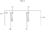
- the upper seats 143 and 145 have a bottom surface formed to extend horizontally or to be inclined rearwards and downwards. As illustrated in FIG. 4 , the upper seat 143 of each first guide slot 142 may be formed to extend horizontally, whereas the upper seat 145 of each guide slot 144 may be formed to be inclined rearwards and downwards from a bent portion of the upper end of the second guide slot 144.
- Each guide protrusion 146 has a circular cross-section and, as such, the end portions of the upper and lower seats in each guide slot may have a semi-circular shape.
- Each second guide slot 144 may be formed such that the bent portion thereof disposed adjacent to the upper seat 145 has a level higher than a lower end of the upper seat 145.
- the guide protrusion 146, which has been supported by the upper seat 145 of each second guide slot 144 is prevented from being easily separated from the upper seat 145. It may be possible to prevent the shelf 120 from being unintentionally moved downwards even when the user touches the shelf 120 or impact is applied to the refrigerator in a state in which the shelf 120 is positioned at a raised position thereof.
- each first guide slot 142 is formed not to be inclined. This is because operation of the user to lower the shelf 120 from a raised position of the shelf 120 may be difficult when the upper seat 143 is inclinedly formed, and the guide protrusion 146 may be easily moved to the upper seat 143 when the upper seat 143 is formed to extend horizontally.
- a selected one of the two guide slots namely, the second guide slot 144, is inclinedly formed is to achieve convenience of user's operation because the user lowers the shelf 120 from the raised position while slightly lifting the shelf 120 under the condition that the user grasps a front lower surface of the shelf 120.
- rollers 146a and 146b may be mounted to the first and second guide protrusions 146, respectively.
- the rollers 146a and 146b namely, the first roller 146a to be engaged in the corresponding first guide slot 142 and the second roller 146b to be engaged in the corresponding second guide slot 144, are identical in that they are fastened by screws S, even though they have slightly different shapes.
- each first guide slot 142 takes the form of a groove having a certain depth without extending through the inner surface of the guide member 140
- each first roller 146a is formed to have a slightly smaller diameter than the width of each first guide slot 142.
- Each second guide slot 144 is formed to extend through the guide member 140 and, as such, each second roller 146b may be mounted in the corresponding second guide slot 144 while extending through the second guide slot 144.
- a step 147 is provided at an outer portion of each guide slot 144, to increase the width of the guide slot 144.
- the second roller 146b which is engaged in the guide slot 144, has a stepped structure, to be supported by the step 147 while contacting the step 147 after passing through the second guide slot 144.
- the second roller 146b is mounted without protruding from the outer surface of the second guide slot 144, to allow the guide member 140 to closely contact the side surfaces of the refrigerating compartment 20.
- the second roller 146b may be prevented from protruding from the outer surface of the guide member 140 by forming the step 147 at the second guide slot 144, and forming the second roller 146b movably supported by the second guide slot 144 and step 147 to be stepped corresponding to the second guide slot 144.
- stepped second rollers 146b are provided at each pair of second guide protrusions 146, and are supported by the steps 147 of each pair of the second guide slots 144, it may be possible to prevent the shelf 20 from being inclined in a left or right direction during movement thereof.
- shelf 20 If the shelf 20 is inclined during movement thereof between raised and lowered positions, articles placed thereon may fall.
- the shelf 20 may be maintained in a horizontal state during movement thereof because the stepped surfaces of the second rollers 146b are supported by the surfaces of the steps 147, respectively.
- the shelf 120 may include a peripheral portion 122 to be movable between raised and lowered positions while being guided by the guide member 140, and a shelf portion 124 mounted to the peripheral portion 122 inside the peripheral portion 122 and made of a transparent material.
- a peripheral portion 122 may mainly be made of a plastic material, to achieve easy molding thereof.
- the shelf portion 124 may be made of a transparent plastic material or a reinforced glass material.
- the guide protrusions 146 may be formed at the peripheral portion 122, to be integrated with the peripheral portion 122.
- Button mounting grooves 181 for button assemblies 180, which will be described later, may also be provided at the peripheral portion 122.
- the shelf assembly 100 further includes a pair of lever assemblies pivotally mounted to respective side walls of the guide member 140, to push the first guide protrusions 146 in a rearward direction when the first guide protrusions 146 move to the upper seats 143 of the first guide slots 142, respectively.
- Each lever assembly is pivotally mounted at a position adjacent to the corresponding first guide slot 142, and elastically pushes the corresponding first guide protrusion 146 in a rearward direction when the first guide protrusion 146 approaches the upper seat 143 of the first guide slot 142 or is seated in the upper seat 143.
- each first guide slot 142 is horizontally formed. Once the corresponding first guide protrusion 146 moves to the bent portion of the first guide slot 142, the first guide protrusion 146 may be smoothly seated in the upper seat 143 while being pushed by the corresponding lever assembly.
- Each of the lever assemblies includes a lever guide groove 150 formed at the corresponding side wall of the guide member 140 while having a concave shape, a pivotal pin 151 protruding from the lever guide groove 150, a lever member 160 pivotally mounted to the pivotal pin 151 in the lever guide groove 150, and an elastic member 166 disposed between one side surface of the lever guide groove 150 and the lever member 160, to push the lever member 160 in a rearward direction.
- the lever guide groove 150 is formed at a position adjacent to a front side of the guide groove 142 on the outer surface of the corresponding side wall of the guide member 140 while having a concave shape.
- the lever guide groove 150 functions to guide pivotal movement of the lever member 160 while supporting the lever member 160. Accordingly, the lever guide groove 150 may generally take the form of an arc extending through a predetermined angle.
- the pivotal pin 151 protrudes from a lower portion of the lever guide groove 150.
- the lever member 160 is formed, at a lower end thereof, with a pivotal pin hole 161 and, as such, may be pivotably mounted to the pivotal pin 151.
- the lever member 160 is mounted to the pivotal pin 151 by a fastener such as a screw.
- the pivotal pin 151 takes the form of a boss formed with a screw hole.
- the elastic member 166 is disposed between one side surface of the lever guide groove 150 and the lever member 160, to supply elastic force for urging the lever member 160 toward the upper seat 143.
- An elastic member support groove 156 is provided at one side surface of the lever guide groove 150, and an elastic member receiving groove 165 is provided at one side of the lever member 160, for mounting of the elastic member 166.
- the elastic member support groove 156 and elastic member receiving groove 165 function to support the elastic member 166 in order to prevent the elastic member 166 from being separated from a mounted position thereof even when compressed or extended.
- One of the grooves 156 and 165 may take the form of a protrusion, or each of the grooves 156 and 165 may take the form of a protrusion.
- the elastic member 166 is illustrated as being a coil spring. However, a torsion spring or a spring of another form may be used, so long as it supplies elastic force capable of pivoting the lever member 160 in one direction.
- a through hole 153 to be connected to the first guide slot 142 may be formed at an upper portion of a rear side wall of the lever guide groove 150.
- a push portion 163 formed at an upper rear portion of the lever member 160 may push the first guide protrusion 146 while selectively passing through the through hole 153.
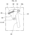
- each guide protrusion and each lever assembly Operations of each guide protrusion and each lever assembly will be described with reference to FIGs. 5A to 5C .
- the user lifts the shelf 120, thereby causing the first guide protrusions 146 or first rollers 146a to move upwards along the first guide slots 142, respectively.
- Each lever member 160 is pushed by the corresponding first roller 146a, thereby causing the corresponding elastic member 166 to be compressed, and elastic energy is accumulated in the compressed elastic member 166.
- the first roller 146a moves to an uppermost position thereof, as illustrated in FIG. 5B , the corresponding lever member 160 pushes the first roller 146a into the corresponding upper seat 143 by compressive force of the compressed elastic member 166.
- the first roller 146a is seated in and supported by the upper seat 143, as illustrated in FIG. 5C . Although the bottom surface of the upper seat 143 is horizontal, the first roller 146a is prevented from being easily separated from the upper seat 143 because the lever member 160 continuously elastically pushes the first roller 146a.
- the shelf assembly 100 may further include a pair of button assemblies 180 provided at opposite sides of a front portion of the shelf 120 and configured to retract locking protrusions 183 thereof from a state of extending outwards from respective lateral sides of the shelf 120 when the button assemblies 180 operate.
- Locking grooves 148 are formed at respective side walls of the guide member 140 to selectively receive respective locking protrusions 183.
- the button assemblies 180 are arranged at opposite sides of the front portion of the shelf 120, the user may easily lower the shelf 120 from a raised position to a lowered position while depressing buttons of the button assemblies 1280 by both hands.
- the locking protrusions 183 which have been extended outwards from respective lateral sides of the shelf 120, are retracted from respective lateral sides of the shelf 120.
- a pair of locking grooves 148 is formed at positions corresponding to respective locking protrusions 183 on respective inner surfaces of the side walls of the guide member 140, as described above.
- the positions corresponding to respective locking protrusions 183 mean positions at which the locking protrusions 183 are insertable into the locking grooves 148, respectively, when the shelf 120 is positioned at a raised position.
- the button assemblies 180 are safety devices for preventing the shelf 120 from unintentionally falling from a raised position, together with the inclined upper seats 145 and lever assemblies.
- each of the button assemblies 180 may include one button mounting groove 181 provided at a corresponding one of the opposite sides of the front portion of the shelf 120, a slider 182 slidably mounted in the button mounting groove 181 and formed, at one end thereof, with the corresponding locking protrusion 183, a button 188 to laterally move the slider 182 when pressed by the user, and an elastic member 185 disposed between the slider 182 and one side surface of the button mounting groove 181, to push the slider 182 outwards.
- the button mounting groove 181 may be formed at the peripheral portion 122 of the shelf 120, to be integrated therewith. Alternatively, the button mounting groove 181 may take the form of a separate member, to be coupled to the peripheral portion 122. A hole is formed through one side surface of the button mounting groove 181, to allow the locking protrusion 183 to pass therethrough.
- the slider 182 which is formed, at one end thereof, with the corresponding locking protrusion 183, to be integrated therewith, is mounted in the button mounting groove 181, to be laterally slidable.
- the elastic member 185 is mounted between the slider 182 and one side surface of the button mounting groove 181, to supply elastic force urging the slider 182 toward the locking protrusion 183.
- a groove may be formed at one side surface of the slider 182, to receive one end of the elastic member 185.
- a protrusion may be formed in place of the groove.
- the button 188 laterally moves the slider 182 when pressed by the user.
- the slider 182 In order to retract the locking protrusion 183, the slider should be moved in a left or right direction.
- the slider 182 may be provided with a handle portion protruding above an upper surface of the shelf 120 while taking the form of a protrusion.
- the user When it is desired to lower the shelf 120, the user should release the locked state of the shelf 120 by pushing the handle portions of the sliders 182 in the button assemblies 180 in left and right directions, and should then lower the shelf 120 while maintaining the released state of the shelf 120.
- operation of lowering the shelf 120 while pushing the handle portions in left and right directions and supporting a lower surface of the shelf 120 by both hands may be difficult.
- the corresponding button assembly 180 may further include a cover member 186 covering the corresponding button mounting groove 181 while being provided with a guide groove 187 to guide movement of the button 188.
- the guide groove 187 is formed at a central portion of the cover member 186 while taking the form of a through hole and, as such, guides vertical movement of the button 188, which is slidably fitted in the guide groove 187.
- the button 188 may generally have a rectangular parallelepiped shape. Accordingly, the guide groove 187 may also be formed in a rectangular shape.
- the cover member 186 may be formed, at a lower surface thereof, with coupling ribs to be engaged with an inner surface of the corresponding button mounting groove 181, in order to be coupled with the button mounting groove 181.
- a stopper protrusion may be formed at a lower end of each button 188 in order to prevent the button 188 from being easily separated in an upward direction after being mounted in the guide groove 187 of the corresponding cover member 186.
- a receiving groove may be provided at an upper surface of each slider 182, to receive a lower portion of the corresponding button 188 when the button 188 is pressed.
- Each button 188 may be also provided with an inclined surface 189 at a lower portion of one side thereof.
- the receiving groove of the corresponding slider 182 includes an inclined surface 184 formed at one side of the receiving groove, to slide while contacting the inclined surface 189. In accordance with contact-sliding movements of the inclined surface 189 of the button 188 and the inclined surface 184 of the slider 182, downward movement of the button 188 may be converted into lateral movement of the slider 182.
- each button assembly will be described with reference to FIGs. 6A and 6B .
- the following description will be given only in conjunction with one button assembly, for convenience of description.
- the inclined surface 189 is moved downwards along the inclined surface 184 of the slider 182, thereby laterally pushing the slider 182 against elastic force of the elastic member 185. Then, the user may pull the shelf 120 downwards in a state of pressing the button 188.
- the refrigerator which includes the shelf assembly according to the present disclosure, may not only achieve easy manufacture thereof and easy operation for vertical movement of the shelf, but also prevent the shelf from falling from a raised position due to carelessness or impact, because the structure of the shelf assembly is simple.
- the present disclosure provides a refrigerator having a simple structure capable of easily achieving level adjustment of a shelf.
- a refrigerator has a safety device capable of preventing a shelf from unintentionally moving from an upper position to a lower position.
- a refrigerator may include a cabinet defined with a storage chamber therein, and a shelf assembly mounted in the storage chamber, the shelf assembly being provided with a vertically movable shelf, wherein the shelf assembly includes a guide member mounted in the storage chamber, and provided with guide slots inclinedly formed at side walls of the guide member, the shelf being supported by the guide member, to be vertically movable, and guide protrusions provided at opposite lateral ends of the shelf, to protrude laterally, and supported by the guide slots in a state of being slidably engaged in the guide slots, wherein the guide slots have bent upper ends forming upper seats to support the guide protrusions, respectively, and each of the upper seats is formed such that a straight vertical line extending downwards from a center of the upper seat passes through a center of a lower seat formed at a corresponding one of the guide slots.
- the guide slots may include a pair of first guide slots each formed at an inner surface of a rear portion in a corresponding one of the side walls of the guide member while taking the form of a groove having a predetermined depth, and a pair of second guide slots each formed at a front portion in the corresponding side wall of the guide member while taking the form of a through hole extending through the side wall.
- the guide protrusions may include a pair of first guide protrusions to be guided by the first guide slots while being engaged in the first guide slots, respectively, and a pair of second guide protrusions to be guided by the second guide slots while being engaged in the second guide slots, respectively.
- Each of the second guide slots may be formed to be inclined downwards from a bent portion of the upper end thereof to the upper seat thereof.
- the shelf assembly further includes a pair of lever assemblies pivotally mounted to the side walls of the guide member, respectively, to push the first guide protrusions in a rearward direction when the first guide protrusions move to the upper seats of the first guide slots, respectively.
- Each of the lever assemblies includes a lever guide groove formed at a corresponding one of the side walls of the guide member while having a concave shape, a pivotal pin protruding from the lever guide groove, a lever member pivotally mounted to the pivotal pin in the lever guide groove, and an elastic member disposed between one side surface of the lever guide groove and the lever member, to push the lever member in a rearward direction.
- the shelf assembly may further include a pair of button assemblies respectively provided at opposite sides of a front portion of the shelf, to retract locking protrusions thereof from a state of extending outwards from respective lateral sides of the shelf when the button assemblies operate, and locking grooves respectively formed at the side walls of the guide member, to selectively receive the locking protrusions.
- Each of the button assemblies may include a button mounting groove provided at a corresponding one of the opposite sides of the front portion of the shelf, a slider slidably mounted in the button mounting groove and formed, at an outer end thereof, with a corresponding one of the locking protrusions, a button to laterally move the slider when pressed by a user, and an elastic member disposed between the slider and an inner side surface of the button mounting groove, to push the slider outwards.
- Each of the button assemblies may further include a cover member covering the button mounting groove while being provided with a guide groove to guide movement of the button.
- the button may include an inclined surface provided at a lower portion of one side of the button.
- the slider may include a receiving groove formed to receive a portion of the button when the button is pressed, and an inclined surface provided at one side of the receiving groove, to slidably contact the inclined surface of the button.
- Each of the lever assemblies may be mounted at a position adjacent to a corresponding one of the first guide slots.
- Each of the second guide slots may be formed such that a bent portion of the second guide slot disposed adjacent to the upper seat of the second guide slot has a level higher than a lower end of the upper seat.
- the guide member may include the side walls including a pair of side walls formed with the guide slots, to guide vertical movement of the shelf while supporting the shelf, and a rear wall connecting rear ends of the pair of side walls.
- the guide member may include the side walls including a pair of side walls respectively mounted to inner side walls of the storage chamber by fasteners and formed with the guide grooves, to guide vertical movement of the shelf while supporting the shelf.
- the shelf may include a peripheral portion to be vertically movable while being guided by the guide member, and a shelf portion mounted to the peripheral portion inside the peripheral portion and made of a transparent material.
- Each of the guide protrusions may include a roller rotatably mounted to the guide protrusion.
- Each of the second guide slots may be provided, at an outer portion thereof, with a step to increase a width of the second guide slot.
- the roller, which is engaged in the second guide slot may have a stepped structure, to be supported by the step while contacting the step after passing through the second guide slot.
- the roller may have a greater outer diameter than an inner width of the second guide slot while being smaller than a width of the step.
- any reference in this specification to "one embodiment,” “an embodiment,” “example embodiment,” etc. means that a particular feature, structure, or characteristic described in connection with the embodiment is included in at least one embodiment of the disclosure.
- the appearances of such phrases in various places in the specification are not necessarily all referring to the same embodiment.
Landscapes
- Engineering & Computer Science (AREA)
- Chemical & Material Sciences (AREA)
- Combustion & Propulsion (AREA)
- Physics & Mathematics (AREA)
- Mechanical Engineering (AREA)
- Thermal Sciences (AREA)
- General Engineering & Computer Science (AREA)
- Refrigerator Housings (AREA)
- Freezers Or Refrigerated Showcases (AREA)
Description
- The present disclosure relates to a refrigerator.
- Generally, a refrigerator is an appliance for storing food, etc. within a storage chamber in a frozen or refrigerated state by discharging, into the storage chamber, cold air generated through a refrigeration cycle constituted by a compressor, a condenser, an expansion valve, an evaporator, etc. Such a refrigerator generally includes a freezing compartment for storing food or beverages in a frozen state, and a refrigerating compartment for storing food or beverages at low temperature. A Kimchi refrigerator, which stores food such as Kimchi or vegetables in a fresh state, is another form of refrigerator.
- At least one of plural doors installed at a refrigerator is connected to one side of a body by a hinge, to open or close a front side of the body through pivotal movement thereof. In addition to such a door, which pivots about a hinge, a drawer type door may also be employed. The drawer type door includes a drawer, and a door mounted to a front side of the drawer, to be withdrawn or retracted in a forward or rearward direction, together with the drawer.
- Generally, storage compartments of a refrigerator, namely, freezing and refrigerating compartments, are provided with a plurality of shelves to vertically divide the freezing and refrigerating compartments into sections, in order to store food articles having various sizes and to enhance space utilization. Since food articles to be placed on such shelves may have various sizes, the shelves are separably mounted at different levels in the freezing and refrigerating compartments while being movable to adjust mounting levels thereof.
- Mounting of the shelves may be achieved by slidably mounting the shelves to a plurality of support ribs formed at left and right surfaces of the refrigerating and freezing compartments, or coupling a pair of cantilevers coupled to each shelf, and then mounting the cantilevers to mounting rails each formed with a plurality of vertically arranged holes.
- Level adjustment of shelves may be difficult and troublesome because, when it is desired to adjust mounting level of a shelf, the user has to separate the shelf from the support ribs or mounting rails after completely removing food articles from the shelf, and then to mount the separated shelf to another level.
- In this regard, the applicant proposed a structure capable of adjusting the level of a shelf while food is placed thereon, as disclosed in Korean Unexamined Patent Publication No.
10-2006-0040290 - There also may be a danger in that, when the shelf is used under a condition that the shelf is disposed at an upper position thereof, and food articles are placed on the shelf, the shelf may be moved to a lower position thereof along the guide slot.
- The above references are appropriate for appropriate teaching of additional or alternative details, features and/or technical background.
-
DE 102010030580 (A1 ) discloses an apparatus with a door arranged in an inner space of the apparatus. Two cams are provided at inside walls of the apparatus. Cooling containers are connected to a stand and the cams. A guide is placed at a lateral holding member and integrated to side walls of the cooling containers. The lateral holding member is placed on an inner side of a frame of a tray plate. The cams are inserted into a receiving opening of the guide. The guide is selected from a group consisting of an arc shaped guide and a C-shaped/S-shaped guide. -
EP2392878 (A ) discloses a directing element for household goods comprising a carrier which has at least one moving element thereon. A directing element is fixed to at least one inner walls of its internal part, and adjusts the height of the carrier by means of the moving element moving therein; the directing element comprises at least one upper channel inclined upwards and at least one lower channel inclined downwards in which the moving element moves, and at least one joint area where one each end of said channels meet and at least one curve located on at least one of the said channels, in which the moving element is seated. -
DE102011075102 (A1 ) discloses a refrigerator having an inner container provided with inner wall that limits a cooling space. A holding device has a holding section that is connected with the inner container and another holding section that is connected with a shelf base. The former holding section has two grooves arranged side by side at the same height. Each groove has locking position bays, which are arranged one above another. The locking positions bays are connected with each other by a groove channel. The latter holding section has holding projections for engaging in the grooves. -
KR950002348 (Y1 - The embodiments will be described in detail with reference to the following drawings in which like reference numerals refer to like elements wherein:
-
FIG. 1 is a perspective view illustrating a bottom freezer type refrigerator equipped with a shelf assembly in accordance with the present disclosure; -
FIG. 2 is a perspective view illustrating a shelf assembly; -
FIG. 3 is an exploded perspective view illustrating an exploded state of the shelf assembly illustrated inFIG. 2 ; -
FIG. 4 is a right side view illustrating a left shelf guide illustrated inFIG. 2 ; -
FIGs. 5A to 5C are right side views illustrating operations of a guide protrusion and a lever assembly provided at the shelf; and -
FIGs. 6A and 6B are sectional views illustrating operation of a button assembly. -
FIG. 1 is a perspective view illustrating a bottom freezer type refrigerator equipped with a shelf assembly in accordance with the present disclosure. The refrigerator includes acabinet 10 defined with a storage chamber therein, and ashelf assembly 100 mounted in the storage chamber, to be vertically movable. - The illustrated refrigerator is a bottom freezer type refrigerator in which a refrigerating
compartment 20 is provided at a top side of thecabinet 10, and a freezing compartment is provided at a bottom side of thecabinet 10. However, the present disclosure may also be applied to refrigerators of other types, so long as theshelf assembly 100 is mountable in a storage chamber such as a refrigerating compartment or a freezing compartment. - Refrigerators of other types include a side-by-side type refrigerator in which a freezing compartment and a refrigerating compartment are laterally arranged, and a top mounting type refrigerator in which a freezing compartment is arranged over a refrigerating compartment. The present disclosure may be applied to a refrigerator including a refrigerating compartment or a freezing compartment alone, so long as the
shelf assembly 100 is mountable in the storage chamber. - The
shelf assembly 100 may mainly be mounted in a refrigerating compartment, but may be mounted to a freezing compartment. The refrigeratingcompartment 20 provided at the top side of thecabinet 10 may be opened or closed by a pair of pivotally-mounted refrigeratingcompartment doors 30. The freezing compartment provided at the bottom side of thecabinet 10 may be opened or closed by afreezing compartment door 40, which is a drawer type door. Of course, thefreezing compartment door 40 may be a pivotally-mounted door, in place of the drawer type door. - The
shelf assembly 100 may mainly be mounted in a lower portion of the refrigeratingcompartment 20, and may include a vertically movable shelf. Theshelf assembly 100 may further include at least one shelf separably mounted on theshelf assembly 100. As illustrated inFIG. 1 , the shelf mounted on theshelf assembly 100 may be supported by cantilevers. This shelf may be also supported by shelf support ribs. -
FIG. 2 is a perspective view illustrating a shelf assembly according to a preferred embodiment of the present disclosure.FIG. 3 is an exploded perspective view illustrating an exploded state of the shelf assembly illustrated inFIG. 2 . - The
shelf assembly 100 may include aguide member 140 mounted in the storage chamber, and provided withguide slots guide member 140. Theshelf assembly 100 also includes ashelf 120 supported by theguide member 140, to be vertically movable, andguide protrusions 146 provided at opposite lateral ends of theshelf 120, to protrude laterally, and supported by theguide slots guide slots - The
guide member 140 may have a plate shape having a predetermined thickness. Theguide slots guide member 140 while having a depth smaller than the thickness of theguide member 140. Theguide member 140 may be mounted to an inner side surface of therefrigerating compartment 20 by fasteners such as screws. - The
guide member 140 may include a pair of side walls each formed with theguide slots shelf 120 while supporting theshelf 120, and arear wall 149 connecting rear ends of the side walls. Theguide member 140 may have a more firm structure, may maintain a desired spacing between the side walls thereof, and may be mounted to be seated on the bottom of therefrigerating compartment 20. - In accordance with the above-described structure of the
guide member 140, it may be possible to easily mount theshelf assembly 100 in therefrigerating compartment 20 in a state of being assembled into a single set. - Of course, the
guide member 140 may be fastened to the inner surface of therefrigerating compartment 20, to be fixed to therefrigerating compartment 20, in order to prevent theguide member 140 from being moved when the user lifts theshelf 120. - In the case in which the
guide member 140 is mounted to the inner side walls of therefrigerating compartment 20 by fasteners, theguide member 140 may only include a pair of side walls while eliminating connection by therear wall 149. The width of theshelf 120 may be determined, taking into consideration the spacing between the side walls of therefrigerating compartment 20 and the thickness of theguide member 140. - The
guide slots guide member 140 while being spaced from each other in forward and rearward directions by a predetermined distance. Twoguide slots guide member 140, and twoguide slots guide member 140. - The
guide slots first guide slots 142 each formed at an inner surface of a rear portion of the corresponding side wall in theguide member 140 while taking the form of a groove having a predetermined depth, and a pair ofsecond guide slots 144 each formed at a front portion of the corresponding side wall in theguide member 140 while taking the form of a through hole extending through the side wall. - The
shelf 120 is supported by theguide member 140, to be vertically movable. The guide protrusions 146 are provided at the opposite lateral ends of theshelf 120, to protrude laterally, and are supported by theguide slots guide slots guide protrusions 146 may be formed at positions corresponding to the fourguide slots guide slots - The guide protrusions 146 may include a pair of
first guide protrusions 146 to be guided by thefirst guide slots 142 while being engaged therein, respectively, and a pair ofsecond guide protrusions 146 to be guided by thesecond guide slots 144 while being engaged therein, respectively. - As illustrated in
FIG. 4 , theguide slots upper seats guide protrusions 146, respectively. Each of theupper seats upper seat corresponding guide slot - Each of the
upper seats guide slots shelf 120 may have the same horizontal position before and after movement thereof. - The
shelf 120 has the same horizontal position in raised and lowered states, except that theshelf 120 has different levels at the raised and lowered positions, and, as such, it may be possible to achieve efficient space utilization in that no dead space is generated due to movement of the shelf. - The
guide slots shelf 120 in forward and rearward directions upon movement of theshelf 120 is increased and, as such, limitation of the length of theshelf 120 in forward and rearward directions is increased. - When the
shelf 120 is lifted, theguide protrusions 146 are moved along theinclined guide slots shelf 120 to move forwards by a predetermined distance and, as such, it may be desirable that the front surface of theshelf 120 not protrude further forward than the front surface of theguide member 140. The inclination angle of theguide slots guide protrusions 146 can be stably seated in theguide slots - The upper ends of the
guide slots upper seats upper seats FIG. 4 , theupper seat 143 of eachfirst guide slot 142 may be formed to extend horizontally, whereas theupper seat 145 of eachguide slot 144 may be formed to be inclined rearwards and downwards from a bent portion of the upper end of thesecond guide slot 144. - Each
guide protrusion 146 has a circular cross-section and, as such, the end portions of the upper and lower seats in each guide slot may have a semi-circular shape. Eachsecond guide slot 144 may be formed such that the bent portion thereof disposed adjacent to theupper seat 145 has a level higher than a lower end of theupper seat 145. Theguide protrusion 146, which has been supported by theupper seat 145 of eachsecond guide slot 144 is prevented from being easily separated from theupper seat 145. It may be possible to prevent theshelf 120 from being unintentionally moved downwards even when the user touches theshelf 120 or impact is applied to the refrigerator in a state in which theshelf 120 is positioned at a raised position thereof. - The
upper seat 143 of eachfirst guide slot 142 is formed not to be inclined. This is because operation of the user to lower theshelf 120 from a raised position of theshelf 120 may be difficult when theupper seat 143 is inclinedly formed, and theguide protrusion 146 may be easily moved to theupper seat 143 when theupper seat 143 is formed to extend horizontally. - The reason why a selected one of the two guide slots, namely, the
second guide slot 144, is inclinedly formed is to achieve convenience of user's operation because the user lowers theshelf 120 from the raised position while slightly lifting theshelf 120 under the condition that the user grasps a front lower surface of theshelf 120. - Meanwhile, as illustrated in
FIG. 3 ,rollers second guide protrusions 146, respectively. Therollers first roller 146a to be engaged in the correspondingfirst guide slot 142 and thesecond roller 146b to be engaged in the correspondingsecond guide slot 144, are identical in that they are fastened by screws S, even though they have slightly different shapes. - When the
rollers second guide protrusions 146, respectively, more smooth movement of the first andsecond guide protrusions 146 may be achieved as therollers guide slots first guide slot 142 takes the form of a groove having a certain depth without extending through the inner surface of theguide member 140, eachfirst roller 146a is formed to have a slightly smaller diameter than the width of eachfirst guide slot 142. Eachsecond guide slot 144 is formed to extend through theguide member 140 and, as such, eachsecond roller 146b may be mounted in the correspondingsecond guide slot 144 while extending through thesecond guide slot 144. - A
step 147 is provided at an outer portion of eachguide slot 144, to increase the width of theguide slot 144. Thesecond roller 146b, which is engaged in theguide slot 144, has a stepped structure, to be supported by thestep 147 while contacting thestep 147 after passing through thesecond guide slot 144. - As compared to mounting each
second roller 146b to protrude from the outer surface of the corresponding through hole-shapedsecond guide slot 144 after completely extending thesecond guide slot 144, thesecond roller 146b is mounted without protruding from the outer surface of thesecond guide slot 144, to allow theguide member 140 to closely contact the side surfaces of therefrigerating compartment 20. - Accordingly, it may be possible to prevent the
second roller 146b from protruding from the outer surface of theguide member 140 by forming thestep 147 at thesecond guide slot 144, and forming thesecond roller 146b movably supported by thesecond guide slot 144 and step 147 to be stepped corresponding to thesecond guide slot 144. - In addition, since the stepped
second rollers 146b are provided at each pair ofsecond guide protrusions 146, and are supported by thesteps 147 of each pair of thesecond guide slots 144, it may be possible to prevent theshelf 20 from being inclined in a left or right direction during movement thereof. - If the
shelf 20 is inclined during movement thereof between raised and lowered positions, articles placed thereon may fall. Theshelf 20 may be maintained in a horizontal state during movement thereof because the stepped surfaces of thesecond rollers 146b are supported by the surfaces of thesteps 147, respectively. - The
shelf 120 may include aperipheral portion 122 to be movable between raised and lowered positions while being guided by theguide member 140, and ashelf portion 124 mounted to theperipheral portion 122 inside theperipheral portion 122 and made of a transparent material. When theshelf 120 is positioned at a raised position, food articles may be placed beneath theshelf 120 and, as such, the user may identify the food articles through thetransparent shelf portion 124. Theperipheral portion 122 may mainly be made of a plastic material, to achieve easy molding thereof. Theshelf portion 124 may be made of a transparent plastic material or a reinforced glass material. - The guide protrusions 146 may be formed at the
peripheral portion 122, to be integrated with theperipheral portion 122.Button mounting grooves 181 forbutton assemblies 180, which will be described later, may also be provided at theperipheral portion 122. - The
shelf assembly 100 further includes a pair of lever assemblies pivotally mounted to respective side walls of theguide member 140, to push thefirst guide protrusions 146 in a rearward direction when thefirst guide protrusions 146 move to theupper seats 143 of thefirst guide slots 142, respectively. Each lever assembly is pivotally mounted at a position adjacent to the correspondingfirst guide slot 142, and elastically pushes the correspondingfirst guide protrusion 146 in a rearward direction when thefirst guide protrusion 146 approaches theupper seat 143 of thefirst guide slot 142 or is seated in theupper seat 143. - The
upper seat 143 of eachfirst guide slot 142 is horizontally formed. Once the correspondingfirst guide protrusion 146 moves to the bent portion of thefirst guide slot 142, thefirst guide protrusion 146 may be smoothly seated in theupper seat 143 while being pushed by the corresponding lever assembly. - Each of the lever assemblies includes a
lever guide groove 150 formed at the corresponding side wall of theguide member 140 while having a concave shape, apivotal pin 151 protruding from thelever guide groove 150, alever member 160 pivotally mounted to thepivotal pin 151 in thelever guide groove 150, and anelastic member 166 disposed between one side surface of thelever guide groove 150 and thelever member 160, to push thelever member 160 in a rearward direction. - The
lever guide groove 150 is formed at a position adjacent to a front side of theguide groove 142 on the outer surface of the corresponding side wall of theguide member 140 while having a concave shape. Thelever guide groove 150 functions to guide pivotal movement of thelever member 160 while supporting thelever member 160. Accordingly, thelever guide groove 150 may generally take the form of an arc extending through a predetermined angle. - The
pivotal pin 151 protrudes from a lower portion of thelever guide groove 150. Thelever member 160 is formed, at a lower end thereof, with apivotal pin hole 161 and, as such, may be pivotably mounted to thepivotal pin 151. Thelever member 160 is mounted to thepivotal pin 151 by a fastener such as a screw. In this case, thepivotal pin 151 takes the form of a boss formed with a screw hole. - The
elastic member 166 is disposed between one side surface of thelever guide groove 150 and thelever member 160, to supply elastic force for urging thelever member 160 toward theupper seat 143. An elasticmember support groove 156 is provided at one side surface of thelever guide groove 150, and an elasticmember receiving groove 165 is provided at one side of thelever member 160, for mounting of theelastic member 166. - The elastic
member support groove 156 and elasticmember receiving groove 165 function to support theelastic member 166 in order to prevent theelastic member 166 from being separated from a mounted position thereof even when compressed or extended. One of thegrooves grooves elastic member 166 is illustrated as being a coil spring. However, a torsion spring or a spring of another form may be used, so long as it supplies elastic force capable of pivoting thelever member 160 in one direction. - A through
hole 153 to be connected to thefirst guide slot 142 may be formed at an upper portion of a rear side wall of thelever guide groove 150. Apush portion 163 formed at an upper rear portion of thelever member 160 may push thefirst guide protrusion 146 while selectively passing through the throughhole 153. - Operations of each guide protrusion and each lever assembly will be described with reference to
FIGs. 5A to 5C . As illustrated inFIG. 5A , the user lifts theshelf 120, thereby causing thefirst guide protrusions 146 orfirst rollers 146a to move upwards along thefirst guide slots 142, respectively. - Each
lever member 160 is pushed by the correspondingfirst roller 146a, thereby causing the correspondingelastic member 166 to be compressed, and elastic energy is accumulated in the compressedelastic member 166. When thefirst roller 146a moves to an uppermost position thereof, as illustrated inFIG. 5B , the correspondinglever member 160 pushes thefirst roller 146a into the correspondingupper seat 143 by compressive force of the compressedelastic member 166. - The
first roller 146a is seated in and supported by theupper seat 143, as illustrated inFIG. 5C . Although the bottom surface of theupper seat 143 is horizontal, thefirst roller 146a is prevented from being easily separated from theupper seat 143 because thelever member 160 continuously elastically pushes thefirst roller 146a. - As illustrated in
FIG. 3 , theshelf assembly 100 may further include a pair ofbutton assemblies 180 provided at opposite sides of a front portion of theshelf 120 and configured to retract lockingprotrusions 183 thereof from a state of extending outwards from respective lateral sides of theshelf 120 when thebutton assemblies 180 operate. Lockinggrooves 148 are formed at respective side walls of theguide member 140 to selectively receiverespective locking protrusions 183. - Since the
button assemblies 180 are arranged at opposite sides of the front portion of theshelf 120, the user may easily lower theshelf 120 from a raised position to a lowered position while depressing buttons of the button assemblies 1280 by both hands. When the user simultaneously operates thebutton assemblies 180, the lockingprotrusions 183, which have been extended outwards from respective lateral sides of theshelf 120, are retracted from respective lateral sides of theshelf 120. - A pair of locking
grooves 148 is formed at positions corresponding to respective lockingprotrusions 183 on respective inner surfaces of the side walls of theguide member 140, as described above. The positions corresponding to respective lockingprotrusions 183 mean positions at which the lockingprotrusions 183 are insertable into the lockinggrooves 148, respectively, when theshelf 120 is positioned at a raised position. - Upon lowering the
shelf 120 from a raised position, the user should release a locked state of theshelf 120 by pressing the buttons of thebutton assemblies 180. In this state, the user may lower theshelf 120 to a lowered position after pulling theshelf 120 forwards. Thebutton assemblies 180 are safety devices for preventing theshelf 120 from unintentionally falling from a raised position, together with the inclinedupper seats 145 and lever assemblies. - As illustrated in
FIG. 3 , each of thebutton assemblies 180 may include onebutton mounting groove 181 provided at a corresponding one of the opposite sides of the front portion of theshelf 120, aslider 182 slidably mounted in thebutton mounting groove 181 and formed, at one end thereof, with thecorresponding locking protrusion 183, abutton 188 to laterally move theslider 182 when pressed by the user, and anelastic member 185 disposed between theslider 182 and one side surface of thebutton mounting groove 181, to push theslider 182 outwards. - The
button mounting groove 181 may be formed at theperipheral portion 122 of theshelf 120, to be integrated therewith. Alternatively, thebutton mounting groove 181 may take the form of a separate member, to be coupled to theperipheral portion 122. A hole is formed through one side surface of thebutton mounting groove 181, to allow the lockingprotrusion 183 to pass therethrough. - The
slider 182, which is formed, at one end thereof, with thecorresponding locking protrusion 183, to be integrated therewith, is mounted in thebutton mounting groove 181, to be laterally slidable. Theelastic member 185 is mounted between theslider 182 and one side surface of thebutton mounting groove 181, to supply elastic force urging theslider 182 toward the lockingprotrusion 183. - As illustrated in
FIG. 3 , a groove may be formed at one side surface of theslider 182, to receive one end of theelastic member 185. Alternatively, a protrusion may be formed in place of the groove. Thebutton 188 laterally moves theslider 182 when pressed by the user. - In order to retract the locking
protrusion 183, the slider should be moved in a left or right direction. To this end, theslider 182 may be provided with a handle portion protruding above an upper surface of theshelf 120 while taking the form of a protrusion. When it is desired to lower theshelf 120, the user should release the locked state of theshelf 120 by pushing the handle portions of thesliders 182 in thebutton assemblies 180 in left and right directions, and should then lower theshelf 120 while maintaining the released state of theshelf 120. However, operation of lowering theshelf 120 while pushing the handle portions in left and right directions and supporting a lower surface of theshelf 120 by both hands may be difficult. - The user may lower the
shelf 120 downwards while pressing thebuttons 188 downwards and, as such, operation of the user to lower theshelf 120 may be more easily carried out. It may be needed to configure thesliders 182 to move in corresponding lateral directions, respectively, when thebuttons 188 are pressed downwards. In order to guide vertical movement of eachbutton 188, thecorresponding button assembly 180 may further include acover member 186 covering the correspondingbutton mounting groove 181 while being provided with aguide groove 187 to guide movement of thebutton 188. - The
guide groove 187 is formed at a central portion of thecover member 186 while taking the form of a through hole and, as such, guides vertical movement of thebutton 188, which is slidably fitted in theguide groove 187. Thebutton 188 may generally have a rectangular parallelepiped shape. Accordingly, theguide groove 187 may also be formed in a rectangular shape. - The
cover member 186 may be formed, at a lower surface thereof, with coupling ribs to be engaged with an inner surface of the correspondingbutton mounting groove 181, in order to be coupled with thebutton mounting groove 181. As illustrated in an enlarged view ofFIG. 3 , a stopper protrusion may be formed at a lower end of eachbutton 188 in order to prevent thebutton 188 from being easily separated in an upward direction after being mounted in theguide groove 187 of thecorresponding cover member 186. - A receiving groove may be provided at an upper surface of each
slider 182, to receive a lower portion of thecorresponding button 188 when thebutton 188 is pressed. Eachbutton 188 may be also provided with aninclined surface 189 at a lower portion of one side thereof. Corresponding to theinclined surface 189 of thebutton 188, the receiving groove of thecorresponding slider 182 includes aninclined surface 184 formed at one side of the receiving groove, to slide while contacting theinclined surface 189. In accordance with contact-sliding movements of theinclined surface 189 of thebutton 188 and theinclined surface 184 of theslider 182, downward movement of thebutton 188 may be converted into lateral movement of theslider 182. - Hereinafter, operation of each button assembly will be described with reference to
FIGs. 6A and 6B . The following description will be given only in conjunction with one button assembly, for convenience of description. - In a normal state, the locking
protrusion 183 has been extended into the lockinggroove 148 by theelastic member 185, to be engaged in the lockinggroove 148, as illustrated inFIG. 6A . In this state, theinclined surface 189 of thebutton 188 has been raised upwards by theinclined surface 184 of theslider 182. - When the user presses the
button 188, as illustrated inFIG. 6B , theinclined surface 189 is moved downwards along theinclined surface 184 of theslider 182, thereby laterally pushing theslider 182 against elastic force of theelastic member 185. Then, the user may pull theshelf 120 downwards in a state of pressing thebutton 188. - When the user releases pressing force applied to the
button 188 under the condition that the lockingprotrusion 183 has been moved together with theshelf 120 after being separated from the lockinggroove 148, theslider 182 is pushed by theelastic member 185, thereby causing the lockingprotrusion 183 to extend again. In this state, although the lockingprotrusion 183 is at an extended position, the user may freely raise or lower theshelf 120 because the lockingprotrusion 183 is slidable along the inner surface of theguide member 140, so long as the lockingprotrusion 183 is again engaged in the lockinggroove 148. - As apparent from the above description, the refrigerator, which includes the shelf assembly according to the present disclosure, may not only achieve easy manufacture thereof and easy operation for vertical movement of the shelf, but also prevent the shelf from falling from a raised position due to carelessness or impact, because the structure of the shelf assembly is simple.
- It will be apparent to those skilled in the art that various modifications and variations can be made in the present disclosure without departing from the scope of the disclosures. Thus, it is intended that the present disclosure covers the modifications and variations of this disclosure provided they come within the scope of the appended claims.
- The present disclosure provides a refrigerator having a simple structure capable of easily achieving level adjustment of a shelf. A refrigerator has a safety device capable of preventing a shelf from unintentionally moving from an upper position to a lower position.
- A refrigerator may include a cabinet defined with a storage chamber therein, and a shelf assembly mounted in the storage chamber, the shelf assembly being provided with a vertically movable shelf, wherein the shelf assembly includes a guide member mounted in the storage chamber, and provided with guide slots inclinedly formed at side walls of the guide member, the shelf being supported by the guide member, to be vertically movable, and guide protrusions provided at opposite lateral ends of the shelf, to protrude laterally, and supported by the guide slots in a state of being slidably engaged in the guide slots, wherein the guide slots have bent upper ends forming upper seats to support the guide protrusions, respectively, and each of the upper seats is formed such that a straight vertical line extending downwards from a center of the upper seat passes through a center of a lower seat formed at a corresponding one of the guide slots.
- The guide slots may include a pair of first guide slots each formed at an inner surface of a rear portion in a corresponding one of the side walls of the guide member while taking the form of a groove having a predetermined depth, and a pair of second guide slots each formed at a front portion in the corresponding side wall of the guide member while taking the form of a through hole extending through the side wall.
- The guide protrusions may include a pair of first guide protrusions to be guided by the first guide slots while being engaged in the first guide slots, respectively, and a pair of second guide protrusions to be guided by the second guide slots while being engaged in the second guide slots, respectively.
- Each of the second guide slots may be formed to be inclined downwards from a bent portion of the upper end thereof to the upper seat thereof.
- The shelf assembly further includes a pair of lever assemblies pivotally mounted to the side walls of the guide member, respectively, to push the first guide protrusions in a rearward direction when the first guide protrusions move to the upper seats of the first guide slots, respectively.
- Each of the lever assemblies includes a lever guide groove formed at a corresponding one of the side walls of the guide member while having a concave shape, a pivotal pin protruding from the lever guide groove, a lever member pivotally mounted to the pivotal pin in the lever guide groove, and an elastic member disposed between one side surface of the lever guide groove and the lever member, to push the lever member in a rearward direction.
- The shelf assembly may further include a pair of button assemblies respectively provided at opposite sides of a front portion of the shelf, to retract locking protrusions thereof from a state of extending outwards from respective lateral sides of the shelf when the button assemblies operate, and locking grooves respectively formed at the side walls of the guide member, to selectively receive the locking protrusions.
- Each of the button assemblies may include a button mounting groove provided at a corresponding one of the opposite sides of the front portion of the shelf, a slider slidably mounted in the button mounting groove and formed, at an outer end thereof, with a corresponding one of the locking protrusions, a button to laterally move the slider when pressed by a user, and an elastic member disposed between the slider and an inner side surface of the button mounting groove, to push the slider outwards.
- Each of the button assemblies may further include a cover member covering the button mounting groove while being provided with a guide groove to guide movement of the button.
- The button may include an inclined surface provided at a lower portion of one side of the button. The slider may include a receiving groove formed to receive a portion of the button when the button is pressed, and an inclined surface provided at one side of the receiving groove, to slidably contact the inclined surface of the button.
- Each of the lever assemblies may be mounted at a position adjacent to a corresponding one of the first guide slots. Each of the second guide slots may be formed such that a bent portion of the second guide slot disposed adjacent to the upper seat of the second guide slot has a level higher than a lower end of the upper seat.
- The guide member may include the side walls including a pair of side walls formed with the guide slots, to guide vertical movement of the shelf while supporting the shelf, and a rear wall connecting rear ends of the pair of side walls.
- Alternatively, the guide member may include the side walls including a pair of side walls respectively mounted to inner side walls of the storage chamber by fasteners and formed with the guide grooves, to guide vertical movement of the shelf while supporting the shelf.
- The shelf may include a peripheral portion to be vertically movable while being guided by the guide member, and a shelf portion mounted to the peripheral portion inside the peripheral portion and made of a transparent material.
- Each of the guide protrusions may include a roller rotatably mounted to the guide protrusion.
- Each of the second guide slots may be provided, at an outer portion thereof, with a step to increase a width of the second guide slot. The roller, which is engaged in the second guide slot, may have a stepped structure, to be supported by the step while contacting the step after passing through the second guide slot.
- The roller may have a greater outer diameter than an inner width of the second guide slot while being smaller than a width of the step.
- In accordance with the aspect of the present disclosure, there is an effect of easily manufacturing the refrigerator because the structure for adjusting the level of the shelf is simple.
- In addition, there is an effect of allowing the user to conveniently use the refrigerator because the operating mechanism for level adjustment of the shelf is simple.
- Furthermore, there is little or no formation of a dead space for allowing movement of the shelf because positions of the shelf in forward and rearward directions in raised and lowered states of the shelf are the same.
- In addition, it may be possible to prevent the shelf from unintentionally falling during use thereof under the condition that the shelf is positioned at a raised position.
- Any reference in this specification to "one embodiment," "an embodiment," "example embodiment," etc., means that a particular feature, structure, or characteristic described in connection with the embodiment is included in at least one embodiment of the disclosure. The appearances of such phrases in various places in the specification are not necessarily all referring to the same embodiment. Further, when a particular feature, structure, or characteristic is described in connection with any embodiment, it is submitted that it is within the purview of one skilled in the art to effect such feature, structure, or characteristic in connection with other ones of the embodiments.
- Although embodiments have been described with reference to a number of illustrative embodiments thereof, it should be understood that numerous other modifications and embodiments can be devised by those skilled in the art that will fall within the scope of the principles of this disclosure. More particularly, various variations and modifications are possible in the component parts and/or arrangements of the subject combination arrangement within the scope of the disclosure, the drawings and the appended claims.
Claims (15)
- A refrigerator comprising:a cabinet (10) having a storage chamber (20) therein; anda shelf assembly (100) provided in the storage chamber, the shelf assembly being provided with a vertically movable shelf (120),wherein the shelf assembly (100) includes:a guide member (140) provided in the storage chamber and having inclined guide slots (142, 144) formed at side walls of the guide member, the shelf (120) being supported by the guide member, to be vertically movable; andguide protrusions (146) provided at opposite lateral ends of the shelf (120) and configured to be slidably engaged in the guide slots (142, 144),wherein each guide slot (142, 144) has a bent upper end forming an upper seat (143, 145) to support a corresponding guide protrusion (146), and the upper seat (143, 145) is formed such that a straight vertical line extending downwards from a center of the upper seat passes through the center of a lower seat of the guide slot (142, 144) anda pair of lever assemblies pivotally provided to the side walls of the guide member (140) and arranged to push the guide protrusions (146) in a rearward direction when the guide protrusions move to the upper seats (143, 145) of the guide slots (142, 144),wherein each of the lever assemblies comprises:a lever guide groove (150) formed at a corresponding one of the side walls of the guide member (140) and having a concave shape;a pivotal pin (151) protruding from the lever guide groove (150);a lever member (160) pivotally provided to the pivotal pin (151) inthe lever guide groove (150); andan elastic member (166) provided between one side of the lever guide groove (150) and the lever member (160) to push the lever member (160) in the rearward direction.
- The refrigerator according to claim 1, wherein the guide slots (142, 144) comprise:a pair of first guide slots (142), each formed at an inner surface of a rear portion in a corresponding one of the side walls of the guide member (140), and the pair of first guide slots being a pair of grooves having a predetermined depth; anda pair of second guide slots (144), each formed at a front portion in the corresponding side wall of the guide member (140), and the pair of second guide slots being a pair of through-holes extending through the side wall.
- The refrigerator according to claim 1 or 2, wherein the guide protrusions (146) comprise:a pair of first guide protrusions (146) configured to engage in the first guide slots (142) and be guided by the first guide slots; anda pair of second guide protrusions (146) configured to engage in the second guide slots (144) and be guided by the second guide slots.
- The refrigerator according to claim 2 or 3, wherein the bent upper portion of each second guide slot (142, 144) is inclined downwards to the upper seat (143, 145).
- The refrigerator according to any preceding claim, wherein the shelf assembly (100) further comprises:a pair of button assemblies (180) provided at opposite sides of a front portion of the shelf (120) and arranged to retract locking protrusions (183) thereof from a state of extending outwards from respective lateral sides of the shelf when the button assemblies operate; andlocking grooves (148) formed at the side walls of the guide member (140) to selectively receive the locking protrusions.
- The refrigerator according to claim 5, wherein each of the button assemblies (180) comprises:a button mounting groove (181) provided at a corresponding one of the opposite sides of the front portion of the shelf (120);a slider (182) slidably mounted in the button mounting groove and formed, at an outer end thereof, with a corresponding one of the locking protrusions (183);a button (188) arranged to laterally move the slider when pressed by a user; andan elastic member (185) disposed between the slider and an inner side surface of the button mounting groove arranged to push the slider outwards.
- The refrigerator according to claim 6, wherein each of the button assemblies (180) further comprises:
a cover (186) covering the button mounting groove (181) while being provided with a guide groove (187) to guide movement of the button (188). - The refrigerator according to claim 7, wherein
the button (188) includes an inclined surface (189) provided at a lower portion of one side of the button; and
the slider (182) comprises a receiving groove arranged to receive a portion of the button when the button is pressed, and an inclined surface (184) provided at one side of the receiving groove arranged to slidably contact the inclined surface of the button. - The refrigerator according to any one of claims 5 to 8, wherein
each of the lever assemblies is mounted at a position adjacent to a corresponding one of the first guide slots (142); and
each of the second guide slots (144) is formed such that a bent portion of the second guide slot disposed adjacent to the upper seat (145) of the second guide slot has a level higher than a lower end of the upper seat (145). - The refrigerator according to any preceding claim, wherein the side walls are a pair of side walls; and
a rear wall (149) connecting rear ends of the pair of side walls. - The refrigerator according to any preceding claim, wherein the side walls are a pair of side walls mounted to inner side walls of the storage chamber (20) by fasteners and formed with the guide grooves (142, 144).
- The refrigerator according to any preceding claim, wherein the shelf comprises (120):a peripheral portion (122) arranged to be vertically movable and configured to be guided by the guide member; anda shelf portion (124) mounted to the peripheral portion inside the peripheral portion and made of a transparent material.
- The refrigerator according to any preceding claim, wherein each of the guide protrusions (146) comprises a roller (146a, 146b) rotatably mounted to the guide protrusion.
- The refrigerator according to claim 13, wherein each of the second guide slots (144) is provided with a step to increase a width of the second guide slot; and
wherein the roller (146b) is engagable in the second guide slot (144) and has a stepped structure to be supported by the step while contacting the step after passing through the second guide slot. - The refrigerator according to claim 14, wherein the roller (146b) has a greater outer diameter than an inner width of the second guide slot (144) and is smaller than a width of the step.
Applications Claiming Priority (1)
| Application Number | Priority Date | Filing Date | Title |
|---|---|---|---|
| KR1020140036537A KR101622229B1 (en) | 2014-03-28 | 2014-03-28 | Refrigerator |
Publications (3)
| Publication Number | Publication Date |
|---|---|
| EP2924377A2 EP2924377A2 (en) | 2015-09-30 |
| EP2924377A3 EP2924377A3 (en) | 2015-11-04 |
| EP2924377B1 true EP2924377B1 (en) | 2019-10-16 |
Family
ID=52648925
Family Applications (1)
| Application Number | Title | Priority Date | Filing Date |
|---|---|---|---|
| EP15158851.4A Active EP2924377B1 (en) | 2014-03-28 | 2015-03-12 | Refrigerator |
Country Status (3)
| Country | Link |
|---|---|
| US (1) | US9638458B2 (en) |
| EP (1) | EP2924377B1 (en) |
| KR (1) | KR101622229B1 (en) |
Families Citing this family (8)
| Publication number | Priority date | Publication date | Assignee | Title |
|---|---|---|---|---|
| KR102100192B1 (en) * | 2013-09-13 | 2020-04-13 | 엘지전자 주식회사 | Refrigerator |
| BR102015006334B1 (en) * | 2015-03-20 | 2022-09-13 | Whirlpool S.A. | ADJUSTABLE SHELF SYSTEM FOR HOUSEHOLD APPLIANCES |
| CN106440649B (en) * | 2016-11-01 | 2019-03-19 | 泰州乐金电子冷机有限公司 | Height-adjustable refrigerator shelf |
| CN106382787B (en) * | 2016-11-01 | 2019-03-19 | 泰州乐金电子冷机有限公司 | Height-adjustable refrigerator shelf |
| CN106500447A (en) * | 2016-12-22 | 2017-03-15 | 合肥雪祺电气有限公司 | Refrigerator shelf mounting structure and refrigerator |
| US10451336B2 (en) * | 2017-10-12 | 2019-10-22 | Whirlpool Corporation | Adjustable refrigerator compartment and door assembly |
| CN111649530A (en) * | 2020-06-05 | 2020-09-11 | 长虹美菱股份有限公司 | Automatic lifting shelf structure |
| US11435133B1 (en) | 2021-04-26 | 2022-09-06 | Whirlpool Corporation | Refrigerator and shelving system for a refrigerator |
Citations (1)
| Publication number | Priority date | Publication date | Assignee | Title |
|---|---|---|---|---|
| EP2392878A2 (en) * | 2010-06-04 | 2011-12-07 | Vestel Beyaz Esya Sanayi Ve Ticaret A.S. | Height Adjustable Carrier |
Family Cites Families (30)
| Publication number | Priority date | Publication date | Assignee | Title |
|---|---|---|---|---|
| US1257998A (en) * | 1917-10-11 | 1918-03-05 | Archibald B Gruber | Push-button latch. |
| US2739864A (en) * | 1954-07-14 | 1956-03-27 | Gen Motors Corp | Vertically adjustable refrigerator shelf support |
| US3113818A (en) * | 1962-02-13 | 1963-12-10 | Gen Motors Corp | Vertically adjustable cabinet shelf |
| US3292986A (en) * | 1964-06-22 | 1966-12-20 | Morton Mfg Company | Rail slide |
| US3516369A (en) * | 1968-09-27 | 1970-06-23 | Gen Electric | Vertically adjustable shelf |
| US3859932A (en) * | 1973-09-06 | 1975-01-14 | Gen Electric | Adjustable shelf assembly |
| KR0110439Y1 (en) | 1992-08-12 | 1998-04-06 | 강진구 | Battery holder |
| KR950002348Y1 (en) | 1992-10-16 | 1995-03-31 | 이헌조 | Device for controlling shelf height of refrigerator |
| KR970011754A (en) | 1995-08-04 | 1997-03-27 | 배순훈 | Refrigerator |
| JPH09250870A (en) * | 1996-03-19 | 1997-09-22 | Toshiba Corp | Shelf structure of refrigerator |
| JP2003269857A (en) * | 2002-03-13 | 2003-09-25 | Sanyo Electric Co Ltd | Household refrigerator |
| JP2003294357A (en) * | 2002-04-01 | 2003-10-15 | Toshiba Corp | Refrigerator |
| AU2003247324A1 (en) * | 2002-05-10 | 2003-11-11 | Arcelik A. S¸ | A household appliance |
| BR0302251A (en) * | 2003-06-27 | 2005-03-15 | Multibras Eletrodomesticos Sa | Folding shelf for refrigerator cabinet |
| US7621605B2 (en) * | 2004-09-30 | 2009-11-24 | Easy Lift Llc | Shelf extending and lifting system |
| KR20060030563A (en) * | 2004-10-06 | 2006-04-11 | 엘지전자 주식회사 | Vertically adjustable strucrure of shelf for refrigerator |
| KR101035144B1 (en) | 2004-11-05 | 2011-05-17 | 엘지전자 주식회사 | Vertically adjustable strucrure of shelf for refrigerator |
| CN2757207Y (en) * | 2004-11-15 | 2006-02-08 | 鸿富锦精密工业(深圳)有限公司 | Computer casing lid fixer |
| US20060254996A1 (en) * | 2005-05-12 | 2006-11-16 | Mcafee Gary | Adjustable shelf system |
| US8333446B2 (en) * | 2006-05-30 | 2012-12-18 | Lg Electronics Inc. | Apparatus for preventing leakage of cooling air for refrigerator |
| CH699347B1 (en) * | 2007-02-09 | 2010-02-26 | Forster Kuechen Und Kuehltechnik | Refrigerator with at least one shelf. |
| KR101291208B1 (en) * | 2008-06-12 | 2013-07-31 | 삼성전자주식회사 | Refrigerator |
| US8052236B2 (en) * | 2009-01-15 | 2011-11-08 | Lg Electronics Inc. | Refrigerator |
| BRMU8900569U2 (en) * | 2009-04-16 | 2010-12-21 | Electrolux Do Brasil Sa | sliding shelves for refrigerators and freezers |
| TR200903811A1 (en) * | 2009-05-15 | 2010-12-21 | Vestel Beyaz Eşya Sanayi̇ Ve Ti̇caret Anoni̇m Şi̇rketi̇@ | A shelf assembly. |
| WO2011160699A1 (en) * | 2010-06-25 | 2011-12-29 | BSH Bosch und Siemens Hausgeräte GmbH | Domestic refrigerator |
| DE102010030580A1 (en) | 2010-06-28 | 2011-12-29 | BSH Bosch und Siemens Hausgeräte GmbH | Closed household cold apparatus i.e. refrigerator, has two cams provided at inside walls of apparatus, cooling containers connected to stand and cams, and guide placed at lateral holding member and integrated to side walls of containers |
| WO2012062675A2 (en) * | 2010-11-12 | 2012-05-18 | Arcelik Anonim Sirketi | A cooling device wherein shelf height can be changed |
| DE102011075102A1 (en) | 2011-05-02 | 2012-11-08 | BSH Bosch und Siemens Hausgeräte GmbH | Refrigerator, particularly household refrigerator or wine storage cabinet, for use in home or in hospitality sector, has holding section provided with two grooves arranged side by side, where each groove has locking positions bays |
| KR101911955B1 (en) * | 2011-10-26 | 2018-10-26 | 엘지전자 주식회사 | Refrigerator |
-
2014
- 2014-03-28 KR KR1020140036537A patent/KR101622229B1/en active IP Right Grant
-
2015
- 2015-02-25 US US14/631,505 patent/US9638458B2/en active Active
- 2015-03-12 EP EP15158851.4A patent/EP2924377B1/en active Active
Patent Citations (1)
| Publication number | Priority date | Publication date | Assignee | Title |
|---|---|---|---|---|
| EP2392878A2 (en) * | 2010-06-04 | 2011-12-07 | Vestel Beyaz Esya Sanayi Ve Ticaret A.S. | Height Adjustable Carrier |
Also Published As
| Publication number | Publication date |
|---|---|
| EP2924377A3 (en) | 2015-11-04 |
| US20150276304A1 (en) | 2015-10-01 |
| KR101622229B1 (en) | 2016-05-18 |
| KR20150112410A (en) | 2015-10-07 |
| US9638458B2 (en) | 2017-05-02 |
| EP2924377A2 (en) | 2015-09-30 |
Similar Documents
| Publication | Publication Date | Title |
|---|---|---|
| EP2924377B1 (en) | Refrigerator | |
| EP2937652B1 (en) | Refrigerator | |
| KR102043198B1 (en) | Refrigerator | |
| EP2775238B1 (en) | Refrigerator | |
| KR100854827B1 (en) | Elevation adjustment structure of shelf for refrigerator | |
| KR102186243B1 (en) | Refrigerator | |
| EP2933590B1 (en) | Refrigerator | |
| US8926034B2 (en) | Refrigerator | |
| EP3742092B1 (en) | Refrigerator and refrigerator door | |
| WO2008062965A1 (en) | Elevation adjustment apparatus for shelf in refrigerator | |
| KR101657118B1 (en) | An assembly of a storage shelf and a refrigerator having the assembly of the storage shelf | |
| KR20160081651A (en) | Refrigerator | |
| KR20140134865A (en) | Refrigerator | |
| KR101869556B1 (en) | Refrigerator | |
| US20210102750A1 (en) | Storage structure for refrigerator appliance | |
| KR101721882B1 (en) | Refrigerator | |
| KR102143016B1 (en) | basket for refrigerator | |
| KR100392393B1 (en) | Refrigerator | |
| CN212057913U (en) | Device for storing and refrigerator | |
| JP2003322461A (en) | Refrigerator | |
| KR20200124864A (en) | Refrigerator | |
| KR20060022427A (en) | A double-drawer of refrigerator |
Legal Events
| Date | Code | Title | Description |
|---|---|---|---|
| PUAI | Public reference made under article 153(3) epc to a published international application that has entered the european phase |
Free format text: ORIGINAL CODE: 0009012 |
|
| 17P | Request for examination filed |
Effective date: 20150312 |
|
| AK | Designated contracting states |
Kind code of ref document: A2 Designated state(s): AL AT BE BG CH CY CZ DE DK EE ES FI FR GB GR HR HU IE IS IT LI LT LU LV MC MK MT NL NO PL PT RO RS SE SI SK SM TR |
|
| AX | Request for extension of the european patent |
Extension state: BA ME |
|
| PUAL | Search report despatched |
Free format text: ORIGINAL CODE: 0009013 |
|
| AK | Designated contracting states |
Kind code of ref document: A3 Designated state(s): AL AT BE BG CH CY CZ DE DK EE ES FI FR GB GR HR HU IE IS IT LI LT LU LV MC MK MT NL NO PL PT RO RS SE SI SK SM TR |
|
| AX | Request for extension of the european patent |
Extension state: BA ME |
|
| RIC1 | Information provided on ipc code assigned before grant |
Ipc: F25D 25/02 20060101AFI20150928BHEP Ipc: A47B 57/10 20060101ALI20150928BHEP Ipc: F25D 25/04 20060101ALN20150928BHEP |
|
| RBV | Designated contracting states (corrected) |
Designated state(s): AL AT BE BG CH CY CZ DE DK EE ES FI FR GB GR HR HU IE IS IT LI LT LU LV MC MK MT NL NO PL PT RO RS SE SI SK SM TR |
|
| RIC1 | Information provided on ipc code assigned before grant |
Ipc: F25D 25/04 20060101ALN20181010BHEP Ipc: F25D 25/02 20060101AFI20181010BHEP Ipc: A47B 57/08 20060101ALN20181010BHEP |
|
| GRAP | Despatch of communication of intention to grant a patent |
Free format text: ORIGINAL CODE: EPIDOSNIGR1 |
|
| STAA | Information on the status of an ep patent application or granted ep patent |
Free format text: STATUS: GRANT OF PATENT IS INTENDED |
|
| RIC1 | Information provided on ipc code assigned before grant |
Ipc: F25D 25/04 20060101ALN20181030BHEP Ipc: A47B 57/08 20060101ALN20181030BHEP Ipc: F25D 25/02 20060101AFI20181030BHEP |
|
| INTG | Intention to grant announced |
Effective date: 20181116 |
|
| GRAJ | Information related to disapproval of communication of intention to grant by the applicant or resumption of examination proceedings by the epo deleted |
Free format text: ORIGINAL CODE: EPIDOSDIGR1 |
|
| STAA | Information on the status of an ep patent application or granted ep patent |
Free format text: STATUS: REQUEST FOR EXAMINATION WAS MADE |
|
| INTC | Intention to grant announced (deleted) | ||
| GRAP | Despatch of communication of intention to grant a patent |
Free format text: ORIGINAL CODE: EPIDOSNIGR1 |
|
| STAA | Information on the status of an ep patent application or granted ep patent |
Free format text: STATUS: GRANT OF PATENT IS INTENDED |
|
| INTG | Intention to grant announced |
Effective date: 20190426 |
|
| RIC1 | Information provided on ipc code assigned before grant |
Ipc: F25D 25/04 20060101ALN20190415BHEP Ipc: A47B 57/08 20060101ALN20190415BHEP Ipc: F25D 25/02 20060101AFI20190415BHEP |
|
| GRAS | Grant fee paid |
Free format text: ORIGINAL CODE: EPIDOSNIGR3 |
|
| GRAA | (expected) grant |
Free format text: ORIGINAL CODE: 0009210 |
|
| STAA | Information on the status of an ep patent application or granted ep patent |
Free format text: STATUS: THE PATENT HAS BEEN GRANTED |
|
| AK | Designated contracting states |
Kind code of ref document: B1 Designated state(s): AL AT BE BG CH CY CZ DE DK EE ES FI FR GB GR HR HU IE IS IT LI LT LU LV MC MK MT NL NO PL PT RO RS SE SI SK SM TR |
|
| REG | Reference to a national code |
Ref country code: GB Ref legal event code: FG4D |
|
| REG | Reference to a national code |
Ref country code: CH Ref legal event code: EP |
|
| REG | Reference to a national code |
Ref country code: DE Ref legal event code: R096 Ref document number: 602015039777 Country of ref document: DE |
|
| REG | Reference to a national code |
Ref country code: IE Ref legal event code: FG4D |
|
| REG | Reference to a national code |
Ref country code: AT Ref legal event code: REF Ref document number: 1191680 Country of ref document: AT Kind code of ref document: T Effective date: 20191115 |
|
| REG | Reference to a national code |
Ref country code: NL Ref legal event code: MP Effective date: 20191016 |
|
| REG | Reference to a national code |
Ref country code: LT Ref legal event code: MG4D |
|
| REG | Reference to a national code |
Ref country code: AT Ref legal event code: MK05 Ref document number: 1191680 Country of ref document: AT Kind code of ref document: T Effective date: 20191016 |
|
| PG25 | Lapsed in a contracting state [announced via postgrant information from national office to epo] |
Ref country code: SE Free format text: LAPSE BECAUSE OF FAILURE TO SUBMIT A TRANSLATION OF THE DESCRIPTION OR TO PAY THE FEE WITHIN THE PRESCRIBED TIME-LIMIT Effective date: 20191016 Ref country code: NL Free format text: LAPSE BECAUSE OF FAILURE TO SUBMIT A TRANSLATION OF THE DESCRIPTION OR TO PAY THE FEE WITHIN THE PRESCRIBED TIME-LIMIT Effective date: 20191016 Ref country code: LV Free format text: LAPSE BECAUSE OF FAILURE TO SUBMIT A TRANSLATION OF THE DESCRIPTION OR TO PAY THE FEE WITHIN THE PRESCRIBED TIME-LIMIT Effective date: 20191016 Ref country code: LT Free format text: LAPSE BECAUSE OF FAILURE TO SUBMIT A TRANSLATION OF THE DESCRIPTION OR TO PAY THE FEE WITHIN THE PRESCRIBED TIME-LIMIT Effective date: 20191016 Ref country code: ES Free format text: LAPSE BECAUSE OF FAILURE TO SUBMIT A TRANSLATION OF THE DESCRIPTION OR TO PAY THE FEE WITHIN THE PRESCRIBED TIME-LIMIT Effective date: 20191016 Ref country code: GR Free format text: LAPSE BECAUSE OF FAILURE TO SUBMIT A TRANSLATION OF THE DESCRIPTION OR TO PAY THE FEE WITHIN THE PRESCRIBED TIME-LIMIT Effective date: 20200117 Ref country code: PL Free format text: LAPSE BECAUSE OF FAILURE TO SUBMIT A TRANSLATION OF THE DESCRIPTION OR TO PAY THE FEE WITHIN THE PRESCRIBED TIME-LIMIT Effective date: 20191016 Ref country code: NO Free format text: LAPSE BECAUSE OF FAILURE TO SUBMIT A TRANSLATION OF THE DESCRIPTION OR TO PAY THE FEE WITHIN THE PRESCRIBED TIME-LIMIT Effective date: 20200116 Ref country code: BG Free format text: LAPSE BECAUSE OF FAILURE TO SUBMIT A TRANSLATION OF THE DESCRIPTION OR TO PAY THE FEE WITHIN THE PRESCRIBED TIME-LIMIT Effective date: 20200116 Ref country code: PT Free format text: LAPSE BECAUSE OF FAILURE TO SUBMIT A TRANSLATION OF THE DESCRIPTION OR TO PAY THE FEE WITHIN THE PRESCRIBED TIME-LIMIT Effective date: 20200217 Ref country code: FI Free format text: LAPSE BECAUSE OF FAILURE TO SUBMIT A TRANSLATION OF THE DESCRIPTION OR TO PAY THE FEE WITHIN THE PRESCRIBED TIME-LIMIT Effective date: 20191016 Ref country code: AT Free format text: LAPSE BECAUSE OF FAILURE TO SUBMIT A TRANSLATION OF THE DESCRIPTION OR TO PAY THE FEE WITHIN THE PRESCRIBED TIME-LIMIT Effective date: 20191016 |
|
| PG25 | Lapsed in a contracting state [announced via postgrant information from national office to epo] |
Ref country code: HR Free format text: LAPSE BECAUSE OF FAILURE TO SUBMIT A TRANSLATION OF THE DESCRIPTION OR TO PAY THE FEE WITHIN THE PRESCRIBED TIME-LIMIT Effective date: 20191016 Ref country code: RS Free format text: LAPSE BECAUSE OF FAILURE TO SUBMIT A TRANSLATION OF THE DESCRIPTION OR TO PAY THE FEE WITHIN THE PRESCRIBED TIME-LIMIT Effective date: 20191016 Ref country code: IS Free format text: LAPSE BECAUSE OF FAILURE TO SUBMIT A TRANSLATION OF THE DESCRIPTION OR TO PAY THE FEE WITHIN THE PRESCRIBED TIME-LIMIT Effective date: 20200224 |
|
| PG25 | Lapsed in a contracting state [announced via postgrant information from national office to epo] |
Ref country code: AL Free format text: LAPSE BECAUSE OF FAILURE TO SUBMIT A TRANSLATION OF THE DESCRIPTION OR TO PAY THE FEE WITHIN THE PRESCRIBED TIME-LIMIT Effective date: 20191016 |
|
| REG | Reference to a national code |
Ref country code: DE Ref legal event code: R097 Ref document number: 602015039777 Country of ref document: DE |
|
| PG2D | Information on lapse in contracting state deleted |
Ref country code: IS |
|
| PG25 | Lapsed in a contracting state [announced via postgrant information from national office to epo] |
Ref country code: CZ Free format text: LAPSE BECAUSE OF FAILURE TO SUBMIT A TRANSLATION OF THE DESCRIPTION OR TO PAY THE FEE WITHIN THE PRESCRIBED TIME-LIMIT Effective date: 20191016 Ref country code: RO Free format text: LAPSE BECAUSE OF FAILURE TO SUBMIT A TRANSLATION OF THE DESCRIPTION OR TO PAY THE FEE WITHIN THE PRESCRIBED TIME-LIMIT Effective date: 20191016 Ref country code: DK Free format text: LAPSE BECAUSE OF FAILURE TO SUBMIT A TRANSLATION OF THE DESCRIPTION OR TO PAY THE FEE WITHIN THE PRESCRIBED TIME-LIMIT Effective date: 20191016 Ref country code: EE Free format text: LAPSE BECAUSE OF FAILURE TO SUBMIT A TRANSLATION OF THE DESCRIPTION OR TO PAY THE FEE WITHIN THE PRESCRIBED TIME-LIMIT Effective date: 20191016 Ref country code: IS Free format text: LAPSE BECAUSE OF FAILURE TO SUBMIT A TRANSLATION OF THE DESCRIPTION OR TO PAY THE FEE WITHIN THE PRESCRIBED TIME-LIMIT Effective date: 20200216 |
|
| PLBE | No opposition filed within time limit |
Free format text: ORIGINAL CODE: 0009261 |
|
| STAA | Information on the status of an ep patent application or granted ep patent |
Free format text: STATUS: NO OPPOSITION FILED WITHIN TIME LIMIT |
|
| PG25 | Lapsed in a contracting state [announced via postgrant information from national office to epo] |
Ref country code: IT Free format text: LAPSE BECAUSE OF FAILURE TO SUBMIT A TRANSLATION OF THE DESCRIPTION OR TO PAY THE FEE WITHIN THE PRESCRIBED TIME-LIMIT Effective date: 20191016 Ref country code: SK Free format text: LAPSE BECAUSE OF FAILURE TO SUBMIT A TRANSLATION OF THE DESCRIPTION OR TO PAY THE FEE WITHIN THE PRESCRIBED TIME-LIMIT Effective date: 20191016 Ref country code: SM Free format text: LAPSE BECAUSE OF FAILURE TO SUBMIT A TRANSLATION OF THE DESCRIPTION OR TO PAY THE FEE WITHIN THE PRESCRIBED TIME-LIMIT Effective date: 20191016 |
|
| 26N | No opposition filed |
Effective date: 20200717 |
|
| PG25 | Lapsed in a contracting state [announced via postgrant information from national office to epo] |
Ref country code: MC Free format text: LAPSE BECAUSE OF FAILURE TO SUBMIT A TRANSLATION OF THE DESCRIPTION OR TO PAY THE FEE WITHIN THE PRESCRIBED TIME-LIMIT Effective date: 20191016 |
|
| REG | Reference to a national code |
Ref country code: CH Ref legal event code: PL |
|
| PG25 | Lapsed in a contracting state [announced via postgrant information from national office to epo] |
Ref country code: SI Free format text: LAPSE BECAUSE OF FAILURE TO SUBMIT A TRANSLATION OF THE DESCRIPTION OR TO PAY THE FEE WITHIN THE PRESCRIBED TIME-LIMIT Effective date: 20191016 |
|
| REG | Reference to a national code |
Ref country code: BE Ref legal event code: MM Effective date: 20200331 |
|
| PG25 | Lapsed in a contracting state [announced via postgrant information from national office to epo] |
Ref country code: LU Free format text: LAPSE BECAUSE OF NON-PAYMENT OF DUE FEES Effective date: 20200312 |
|
| PG25 | Lapsed in a contracting state [announced via postgrant information from national office to epo] |
Ref country code: LI Free format text: LAPSE BECAUSE OF NON-PAYMENT OF DUE FEES Effective date: 20200331 Ref country code: CH Free format text: LAPSE BECAUSE OF NON-PAYMENT OF DUE FEES Effective date: 20200331 Ref country code: IE Free format text: LAPSE BECAUSE OF NON-PAYMENT OF DUE FEES Effective date: 20200312 |
|
| PG25 | Lapsed in a contracting state [announced via postgrant information from national office to epo] |
Ref country code: BE Free format text: LAPSE BECAUSE OF NON-PAYMENT OF DUE FEES Effective date: 20200331 |
|
| PG25 | Lapsed in a contracting state [announced via postgrant information from national office to epo] |
Ref country code: TR Free format text: LAPSE BECAUSE OF FAILURE TO SUBMIT A TRANSLATION OF THE DESCRIPTION OR TO PAY THE FEE WITHIN THE PRESCRIBED TIME-LIMIT Effective date: 20191016 Ref country code: MT Free format text: LAPSE BECAUSE OF FAILURE TO SUBMIT A TRANSLATION OF THE DESCRIPTION OR TO PAY THE FEE WITHIN THE PRESCRIBED TIME-LIMIT Effective date: 20191016 Ref country code: CY Free format text: LAPSE BECAUSE OF FAILURE TO SUBMIT A TRANSLATION OF THE DESCRIPTION OR TO PAY THE FEE WITHIN THE PRESCRIBED TIME-LIMIT Effective date: 20191016 |
|
| PG25 | Lapsed in a contracting state [announced via postgrant information from national office to epo] |
Ref country code: MK Free format text: LAPSE BECAUSE OF FAILURE TO SUBMIT A TRANSLATION OF THE DESCRIPTION OR TO PAY THE FEE WITHIN THE PRESCRIBED TIME-LIMIT Effective date: 20191016 |
|
| PGFP | Annual fee paid to national office [announced via postgrant information from national office to epo] |
Ref country code: FR Payment date: 20230206 Year of fee payment: 9 |
|
| PGFP | Annual fee paid to national office [announced via postgrant information from national office to epo] |
Ref country code: DE Payment date: 20240205 Year of fee payment: 10 Ref country code: GB Payment date: 20240205 Year of fee payment: 10 |