EP2919081A1 - Processing machine taking into account position errors in collision checking - Google Patents
Processing machine taking into account position errors in collision checking Download PDFInfo
- Publication number
- EP2919081A1 EP2919081A1 EP14159692.4A EP14159692A EP2919081A1 EP 2919081 A1 EP2919081 A1 EP 2919081A1 EP 14159692 A EP14159692 A EP 14159692A EP 2919081 A1 EP2919081 A1 EP 2919081A1
- Authority
- EP
- European Patent Office
- Prior art keywords
- tool
- machine
- workpiece
- numerical control
- processing machine
- Prior art date
- Legal status (The legal status is an assumption and is not a legal conclusion. Google has not performed a legal analysis and makes no representation as to the accuracy of the status listed.)
- Granted
Links
Images


Classifications
-
- G—PHYSICS
- G05—CONTROLLING; REGULATING
- G05B—CONTROL OR REGULATING SYSTEMS IN GENERAL; FUNCTIONAL ELEMENTS OF SUCH SYSTEMS; MONITORING OR TESTING ARRANGEMENTS FOR SUCH SYSTEMS OR ELEMENTS
- G05B19/00—Programme-control systems
- G05B19/02—Programme-control systems electric
- G05B19/18—Numerical control [NC], i.e. automatically operating machines, in particular machine tools, e.g. in a manufacturing environment, so as to execute positioning, movement or co-ordinated operations by means of programme data in numerical form
- G05B19/19—Numerical control [NC], i.e. automatically operating machines, in particular machine tools, e.g. in a manufacturing environment, so as to execute positioning, movement or co-ordinated operations by means of programme data in numerical form characterised by positioning or contouring control systems, e.g. to control position from one programmed point to another or to control movement along a programmed continuous path
-
- G—PHYSICS
- G05—CONTROLLING; REGULATING
- G05B—CONTROL OR REGULATING SYSTEMS IN GENERAL; FUNCTIONAL ELEMENTS OF SUCH SYSTEMS; MONITORING OR TESTING ARRANGEMENTS FOR SUCH SYSTEMS OR ELEMENTS
- G05B19/00—Programme-control systems
- G05B19/02—Programme-control systems electric
- G05B19/18—Numerical control [NC], i.e. automatically operating machines, in particular machine tools, e.g. in a manufacturing environment, so as to execute positioning, movement or co-ordinated operations by means of programme data in numerical form
- G05B19/406—Numerical control [NC], i.e. automatically operating machines, in particular machine tools, e.g. in a manufacturing environment, so as to execute positioning, movement or co-ordinated operations by means of programme data in numerical form characterised by monitoring or safety
- G05B19/4061—Avoiding collision or forbidden zones
-
- G—PHYSICS
- G05—CONTROLLING; REGULATING
- G05B—CONTROL OR REGULATING SYSTEMS IN GENERAL; FUNCTIONAL ELEMENTS OF SUCH SYSTEMS; MONITORING OR TESTING ARRANGEMENTS FOR SUCH SYSTEMS OR ELEMENTS
- G05B2219/00—Program-control systems
- G05B2219/30—Nc systems
- G05B2219/41—Servomotor, servo controller till figures
- G05B2219/41439—Position error ffw for compensation of speed
-
- G—PHYSICS
- G05—CONTROLLING; REGULATING
- G05B—CONTROL OR REGULATING SYSTEMS IN GENERAL; FUNCTIONAL ELEMENTS OF SUCH SYSTEMS; MONITORING OR TESTING ARRANGEMENTS FOR SUCH SYSTEMS OR ELEMENTS
- G05B2219/00—Program-control systems
- G05B2219/30—Nc systems
- G05B2219/49—Nc machine tool, till multiple
- G05B2219/49148—Adapt working envelop, limit to size workpiece
-
- G—PHYSICS
- G05—CONTROLLING; REGULATING
- G05B—CONTROL OR REGULATING SYSTEMS IN GENERAL; FUNCTIONAL ELEMENTS OF SUCH SYSTEMS; MONITORING OR TESTING ARRANGEMENTS FOR SUCH SYSTEMS OR ELEMENTS
- G05B2219/00—Program-control systems
- G05B2219/30—Nc systems
- G05B2219/49—Nc machine tool, till multiple
- G05B2219/49157—Limitation, collision, interference, forbidden zones, avoid obstacles
-
- G—PHYSICS
- G05—CONTROLLING; REGULATING
- G05B—CONTROL OR REGULATING SYSTEMS IN GENERAL; FUNCTIONAL ELEMENTS OF SUCH SYSTEMS; MONITORING OR TESTING ARRANGEMENTS FOR SUCH SYSTEMS OR ELEMENTS
- G05B2219/00—Program-control systems
- G05B2219/30—Nc systems
- G05B2219/49—Nc machine tool, till multiple
- G05B2219/49198—Using lookup table, map, position and corresponding quasi static error
Definitions
- the present invention further relates to a system program comprising machine code executable by a numerical controller, wherein the execution of the machine code by the numerical controller causes the numerical controller to execute such an operating method.
- the present invention further relates to a numerical control programmed with such a system program.
- machine tools there is a coordinated process of the position-controlled axes, so that the workpiece is machined by means of the tool according to a machining defined by the part program.
- TCP tool center point
- the real kinematics of the processing machine is not considered in the specification of the TCP. Due to the fact that the real kinematics of the processing machine in the context of the determination of the part program is not known in advance, can not be checked in the part program whether a desired, defined by the parts program processing using the real machine is possible or not.
- protective bodies are assigned to the tool, the workpiece and the machine elements by the numerical control.
- the protective bodies can be defined as true volumes both in the prior art and in the context of the present invention.
- the protective bodies are linked together according to the real kinematics of the processing machine. They are virtually traversed by the numerical control as part of a so-called pre-run, that is, before the real control of the axes, according to the movement to be realized.
- the numerical control checks whether the protective bodies penetrate or touch each other as part of this movement. If this is the case, the protective bodies do not remain disjoint. There is thus an undesirable collision. Otherwise, the real execution of the part program can take place.
- the position setpoints are stored as ideal position setpoints for an ideal processing machine.
- the respective positioning of the tool relative to the workpiece corresponds exactly to the setpoint specification.
- real processing machines have deviations. These deviations include, for example, offsets, zero offsets, linear deviations and rotational deviations.
- a position error field is known to the numerical control which indicates, for any desired axis values, which actual position the tool occupies relative to the workpiece when the position-controlled axes are positioned at the respective axis nominal values.
- the respective positional error is usually defined as a deviation from the corresponding ideal position, which would result if the processing machine were constructed completely error-free. Alternatively, the actual position itself can be stored. Regardless of which procedure is taken, the numerical control is due to the position error field in a position to correct the axis setpoints accordingly, so that as a result, the TCP is positioned correctly, ie according to the specification by the part program.
- the respective positional error comprises - both in the prior art as well as in the context of the present invention - usually at least the (translational) positioning error. In addition, both in the prior art and in the context of the present invention, it can additionally comprise a (rotational) orientation error with one, two or three angles.
- the position error field is used only for correction in the real driving, but not in the context of the lead in the determination of the positions of the protective body and the subsequent test for collisions.
- the object of the present invention is to provide ways by which collisions can be reliably avoided.
- an operating method of the type mentioned at the outset is configured such that the numerical control takes into account the positional error field for at least part of the protective bodies when determining the volumes that would be occupied by the protective bodies when the position-controlled axes are controlled according to the sequence of position setpoints.
- the numerical control takes into account the positional error field for all protection bodies when determining the volumes taken. Although this procedure is completely accurate, it is not necessary in many cases. In general, however, it is necessary for those protective bodies in which the numerical control takes into account the positional error field when determining the occupied volumes to include the tool and a tool holder. In an analogous manner, it is also generally required that those protective bodies in which the numerical control takes into account the positional error field in determining the occupied volumes comprise at least the workpiece and a workpiece holder. If necessary, other protective bodies can of course also be included in this procedure.
- the numerical control in order to optimize the additional effort required to take into account the positional error field in the context of the collision check, it is generally appropriate for the numerical control to take into account the positional error field only when determining the captured volumes of these protective bodies.
- the determination of their respective position is based on the axis setpoint values directly corresponding to the position setpoint values-that is, without taking into account the positional error field.
- the machine elements which are moved by means of the position-controlled axes, follow one another sequentially from the stationary base body of the processing machine to the tool or to the workpiece.
- it is often sufficient when determining the volumes occupied by a protective body corresponding to a specific machine element only take into account the desired axle values of those position-controlled axles which act on machine elements which are arranged between the base body and the specific machine element, viewed from the main body to the tool or to the workpiece.
- the procedure according to the invention can be further optimized in that the numerical control also takes into account a temperature dependence and / or elastic effects in the context of the determination of the volumes occupied by the protective bodies in addition to the positional error field.
- attitude error field - i. the description of the deviation of the TCP from its ideal position, stored in the numerical control, can also define the rotational orientation error (even if it can not be corrected) in addition to the translational positioning error. If this is the case, in the context of determining the volumes occupied by the protective bodies, the numerical control preferably also takes into account the orientation error in addition to the positioning error. This makes it possible to predict or avoid a possible collision even more precisely.
- the numerical control also takes into account the position error field when determining the axis setpoint values. It is possible that the numerical control always takes into account the position error field when determining the axis setpoint values - ie the real control of the position-controlled axes. Alternatively, it is possible for the numerical control to specify a control command by a user and for the numerical control to take into account or not to take into account the positional error field when determining the axis nominal values, depending on the given control command. Irrespective of this, however, the position error field is taken into account by the numerical control in both cases at least for the determination of the volumes of the protective bodies.
- the object is further achieved by a numerical control with the features of claim 11.
- the numerical control is programmed with a system program according to the invention.
- a processing machine in particular a machine tool, with the features of claim 12.
- a processing machine of the type mentioned above is configured in that the numerical control is programmed with a system program according to the invention.
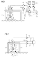
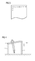
- the directions x, y, z usually define a right-angled Cartesian coordinate system.
- One of the three directions x, y, z - according to the 1 and 2 the third direction z - usually runs vertically.
- the tool 7 By means of the tool 7, the machining of the workpiece 10 takes place.
- Some of the machine elements form a base body of the processing machine, which is not movable or movable.
- these are, for example, the gantry beams 1 and the workpiece table 8.
- Other of the machine elements are positionally movable by means of a respective position-controlled axle 11 to 13 relative to the base body or to the position-controlled machine element to which they are arranged on the base body.
- these are the traverse 2, the carrier 3 and the tool arm 4 with the spindle drive 5 and the further driven by the spindle drive 5 components 6, 7.
- machine elements are compared to the main body or against the position-controlled machine element on which they on the Base body are arranged to, for example, by means of an actuating device, not shown, for example, openable and closable, but not position-controlled movable.
- an actuating device not shown, for example, openable and closable, but not position-controlled movable.
- the processing machine according to the 1 and 2 These are, for example, the tool holder 6 and the workpiece holder 9.
- Other of the machine elements are compared to the main body or against the position-controlled machine element on which they are arranged on the body, only speed controlled rotatable, but not positionally movable.
- the spin drive 5 of the tool holder 6 and with it the tool 7 can be rotationally speed-controlled.
- a spindle drive it is also possible for a spindle drive to also be position-controlled rotatable. This may for example be the case with a spindle drive which rotates the workpiece 10.
- the embodiment of the processing machine according to the 1 and 2 is purely exemplary in several ways. So for example, the processing machine could alternatively to the triaxial embodiment of 1 and 2 be formed four-axis or five-axis. In this case, in addition to the three translational directions x, y, z additionally one or two pivotal movements of the tool 7 relative to the workpiece 10 could be realized. Even more position-controlled axes are possible. Furthermore, the total movement of the tool 7 relative to the workpiece 10 could be completely or partially displaced onto the workpiece 10. Furthermore, other kinematics are possible, for example, an embodiment of the processing machine as a robot, as a tripod or as a hexapod.
- the processing machine has a numerical control 14.
- the numerical controller 14 is programmed with a system program 15.
- the system program 15 can be supplied to the numerical controller 14, for example via a data carrier 16, on which the system program 15 is stored in machine-readable form (for example electronic form). Is purely exemplary in the 1 and 2 the disk 16 shown as a USB memory stick. Also, a supply in other ways is possible, for example via a connection to a data network.
- the system program 15 is usually stored by the manufacturer of the numerical control 14 in the numerical controller 14 and can not be changed by a user.
- the system program 15 includes machine code 17, which can be processed by the numerical control.
- the execution of the machine code 17 by the numerical controller 14 causes the numerical controller 14 to execute an operating method, which will be described later.
- the numerical control 14 is a part program 18 given.
- the part program 18 may be deposited on a further data carrier 19 in machine-readable form and the numerical control via the additional data carrier 19 be supplied.
- a supply in other ways is possible, for example via a connection to a data network.
- the part program 18 contains according to FIG. 3 a sequence of position references p *.
- Each position setpoint p * defines a position which the tool 7 is to occupy relative to the workpiece 10.
- Each position setpoint p * thus defines at least the position of the tool 7 relative to the workpiece 10 in the three translatory directions x, y, z. Because of this, are in FIG.
- the position setpoint p * can additionally comprise an orientation of the tool 7 relative to the workpiece 10 with up to three angles.
- the tool 7 is a rotating tool. In such a case, as shown in FIG FIG. 3 two angles. The angles are in FIG. 3 for the one position setpoint p * with ⁇ and ⁇ indicated.
- the respective position setpoint p * further values are assigned, such as a speed setpoint v *, a speed setpoint n * and / or additional information W.
- the speed setpoint v * indicates how fast the tool 7 at the relevant position setpoint p * relative to the workpiece 10 should be moved.
- the speed setpoint n * indicates with which speed the spindle drive 5 is to rotate the tool holder 6 and the tool 7.
- the additional information W can for example define which of several possible tools 7 should be used.
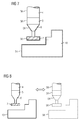
- the individual machine elements 1 to 6, 8 and 9 of the machine tool are not completely ideal.
- the traverse 2 is moved on the gantry beams 1 in the x-direction, would result in an ideal processing machine - as in the 1 and 2
- it can happen that a variety of positioning errors can occur wherein the positioning error both with respect to the traverse 2 as such and with respect to the tool 7 along the position of the traverse 2 in x Direction may vary.
- FIG. 4 at a certain position in the x-direction of the FIG. 4 and FIG. 5 right portal carrier 1 be slightly higher than that in the FIG. 4 and 5 left gantry girder 1.
- the two gantry girders 1 can be the same height or as shown in FIG FIG. 5 even in the FIG. 4 and 5 left portal carrier 1 slightly higher than that in the FIG. 4 and 5 right portal carrier 1. Other incorrect positioning is possible.
- the numerical controller 14 is according to FIG. 1 a position error field F known.
- the position error field F contains the respective corresponding position error F (li *) for any desired combinations of desired axis values li * (or at least for a sufficient number of combinations, so that interpolation is possible for intermediate values).
- the numerical controller 14 first determines the respective desired axle values l.sub.i * on the basis of the desired position values p.sub.x and the ideal kinematics K of the processing machine (known to the numerical controller 14, of course).
- the numerical Control 14 on the basis of the axle setpoint values li *, the kinematic K and the positional error field F which have just been determined, the respective actual position values p.
- the respective actual position value p has, in each case, a coordinate, at least in the three translational directions x, y, z, analogously to the position setpoints p *.
- the respective actual position value p can also - again here analogously to the position setpoints p * - comprise up to three angles.
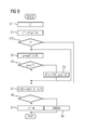
- step S3 the numerical controller 14 checks whether the position actual values p determined in step S2 coincide with the associated position command values p * (within permissible, predefined tolerances). If not, the numerical controller 14 proceeds to a step S4. In step S4, the numerical controller 14 determines, based on the desired axle values li *, the deviation of the actual position values p from the desired position values p * and the kinematics K of the processing machine, new, modified desired axle values li *. Then, the numerical controller 14 returns to step S2. Otherwise, if the determined position actual values p coincide with the associated position setpoint values p *, the determination of the axis nominal values li * is completed.
- axis setpoint values are determined iteratively. However, it may be in accordance with the in FIG. 6 dashed line option be possible to correct the axis setpoint li * only once. In this case, the numerical controller 14 proceeds from step S4 directly to step S5.
- the control of the position-controlled axes 11 to 13 by the numerical controller 14 would now be possible due to the determination of the correct axis desired values li *. If this were done now, there would be a danger of collisions.
- the tool 7 could be provided with machine elements 1 to 3, 8, 9 or (in the case of a contact-type machining, for example a machining, of course, except for the location of the workpiece 10 to be machined by the tool 7) to collide with the workpiece 10.
- a moving machine element 2 to 6 could collide with another machine element 1 to 6, 8, 9 or the workpiece 10.
- the SK protection bodies are in FIG. 7 by way of example for the portion of the tool arm 4 adjoining the spindle drive 5, the spindle drive 5, the tool holder 6, the tool 7 and the workpiece 10 are shown by dashed lines.
- the protective bodies SK are defined so that they match as closely as possible with the respective associated machine element 1 to 6, 8, 9, the workpiece 10 and the tool 7.
- step S5 the numerical controller 14 determines volumes V. Specifically, in step S5, the numerical controller 14 determines, for each combination of axis target values li * determined for a particular position setpoint p *, the volumes V that would be occupied by the guard bodies SK, respectively, when the position-controlled ones Axes 11 to 13 corresponding to the sequence of position setpoint p * (or the corresponding sequences of Achssollept li *) would be driven.
- the protective bodies SK thus form, so to speak, as shown in FIG FIG. 8 a virtual image of the processing machine and are moved virtually.
- the numerical control 14 takes into account in step S5 in the determination of the volumes V - at least for a part of the protective body SK - in addition to the axis target values li * and the position error field F. If the numerical control 14 takes the position error field F, determines the numerical Control 14 in the context of step S5 for the respective protective body SK the correct volume V, ie in particular its position and position.
- the numerical controller 14 thus takes into account, for example, that - see, by way of example FIG. 4 -
- the cross member 2 seen in the z-direction is not exactly above the tool 7, but runs obliquely.
- a step S6 the numerical control 14 checks whether the protective bodies SK remain disjointly in the context of the movement movement simulated by means of the step S5.
- a contact of the tool 7 associated protective body SK is allowed with the workpiece 10 associated protective body SK
- the location of the workpiece 10 at which the contact is permitted may vary over time.
- the protective body SK assigned to the workpiece 10 can vary in time in accordance with the machining by the tool 7.
- Step S7 is executed when the protective bodies SK remain disjointly from each other.
- the numerical controller 14 controls the position-controlled axes 11 to 13 in accordance with the sequence of position command values p *, more precisely, according to the sequence of determined axis target values li *.
- Step S8 is executed when the protective bodies SK do not disjoint stay away from each other. In this case, the control of the position-controlled axes 11 to 13 is suppressed by the numerical controller 14. Furthermore, an error response is executed, for example to an operator 20 (see FIG FIG. 1 ) gives an error message.
- step S5 - for all protective SK.
- critical means that, on the one hand, as part of the machining of the workpiece 10 by the tool 7, there is the possibility that the corresponding elements must be brought very close to each other, but nevertheless must not collide with one another. In these elements, therefore, a highly accurate modeling of the real processing machine and the real workpiece 10 by the corresponding protective body SK and each of the corresponding protective bodies SK occupied volumes V is required.
- the protective bodies SK in which the numerical controller 14 takes into account the positional error field F when determining the occupied volumes V, should therefore comprise on the side of the tool 7 at least the protective bodies SK for the tool 7 and the tool holder 6. If the tool 7 is a rotating tool (for example, a drill or a milling cutter), the same procedure can be taken for the protective body SK for the spindle drive 5. Furthermore, the protective bodies SK, in which the numerical controller 14 takes into account the positional error field F when determining the occupied volumes V, should include on the side of the workpiece 10 at least the protective bodies SK for the workpiece 10 and the workpiece holder or holders 9.
- the portal girders 1, the cross member 2 and the carrier 3 often there is no need from the outset to bring the corresponding elements in close proximity to the other elements.
- the risk of collisions may indeed be excluded by the highly accurate modeling according to the invention.
- the numerical controller 14 does not take into account the positional error field F in the protective bodies SK associated with these machine elements.
- the positional error field F is therefore preferably taken into account only in the case of the protective bodies SK, which are assigned to the abovementioned machine elements 5, 6, 9, the tool 7 and the workpiece 10.
- the numerical control 14 takes into account the positional error field F both in the determination of the desired axle values li * and in the determination of the volumes V occupied by the protective bodies SK.
- This procedure is as a rule to be preferred.
- the operator 20 of the numerical controller 14 as shown in FIG. 1 specifies a control command C.
- the control command C can assume (at least) two different values. If this embodiment is realized, the procedure of FIG. 6 as shown in FIG. 9 modified.
- FIG. 9 comprises the steps S1 to S8 of FIG. 6 , For the steps S1 to S8, therefore, no further comments are required.
- step S11 the numerical controller 14 receives the control command C from the operator 20.
- step S12 the numerical controller 14 checks which value the control command C has. Depending on the value of the control command C, the numerical controller 14 either transfers to step S2 or skips the iteration loop consisting of steps S2 to S4. In the latter case, the numerical controller 14 thus proceeds directly from step S12 to step S5.
- the numerical controller 14 thus takes into account the position error field F in the determination of the desired axle values li * in one case and does not take into account the position error field F in the other case.
- the procedure according to the invention of step S5 is taken in the determination of the volumes V occupied by the protective bodies SK.
- the machine elements 1 to 6, 8, 9 are sufficiently rigid, it is possible to take into account only the desired axle values l.sub.1 * of the upstream position-controlled axles 11 to 13 when determining the volume V occupied by a respective one of the protective bodies SK. It is thus possible to take into account only the desired axle values * of those position-controlled axles 11 to 13 which act on machine elements 1 to 6, 8, 9 which, viewed from the main body to the tool 7 or to the workpiece 10, lie between the main body and the specific machine element 3, 4 are arranged.
- the numerical controller 14 preferably also takes into account, in addition to the positional error field F, elastic effects, for example due to bending moments.
- the extent of elastic deformation of a particular machine element is usually (at least among other things) also dependent on the positioning of downstream machine elements. In this case, therefore, the procedure is usually taken not to take into account only the Achssollowski li * the upstream position-controlled axes 11 to 13 in determining the occupied by a respective one of the protective body SK volume.
- FIG. 5 additionally shows another problem.
- FIG. 5 is - as the only difference to the FIG. 1, 2 and 4 -
- a rotation axis 21 of the spindle drive 5 should be oriented parallel to the z-axis, so This orientation can be taken even if the above-mentioned positioning errors occur.
- the correction of the orientation is possible in a five-axis machine, but not in a three-axis machine in which (ideally) only the three translational directions x, y, z can be set.
- the processing machine is designed as a three-axis machine, by means of which the tool 7 can be positioned translationally relative to the workpiece 10, but not rotationally oriented.
- the position error field F exclusively defines a translational positioning error ⁇ p.
- a rotational orientation error ⁇ o may in this case be defined by the position error field F, but not corrected.
- the position error field F as shown in FIG. 10 explicitly includes the orientation error ⁇ o in addition to the positioning error ⁇ p.
- the orientation error ⁇ o may be determinable, for example, based on gradients of the positioning error ⁇ p as a function of the desired axis values li *. Regardless of which of these cases, it is possible that the numerical controller 14 in the context of determining the occupied by the protective bodies SK volumes V in addition to the positioning error ⁇ p and the orientation error ⁇ o taken into account.
- the axis setpoint values li * represent input variables of the position error field F, the positioning error ⁇ p and possibly also the orientation error ⁇ o output variables. In principle, however, an inverse use of the position error field F is also possible.
- the present invention has many advantages.
- a superior, highly accurate modeling of the movement of the machine elements 1 to 6, 8, 9, the tool 7 and the workpiece 10 and thus a highly accurate collision monitoring in the context of the so-called flow is possible.
Abstract
Einer numerischen Steuerung (14) einer Bearbeitungsmaschine ist ein Teileprogramm (18) vorgegeben, das eine Sequenz von Lagesollwerten (p*) für ein Werkzeug (7) relativ zu einem zu bearbeitenden Werkstück (10) aufweist. Die Steuerung (14) ermittelt anhand der Lagesollwerte (p*) für auf Maschinenelemente (2-4) der Bearbeitungsmaschine wirkende lagegeregelte Achsen (11-13) jeweils einen Achssollwert (li*). Den Maschinenelementen (1-6, 8, 9), dem Werkstück (10) und dem Werkzeug (7) sind innerhalb der Steuerung (14) virtuelle Schutzkörper (SK) zugeordnet. Die Steuerung (14) ermittelt vor dem Ansteuern der lagegeregelten Achsen (11-13) Volumina (V), die von den Schutzkörpern (SK) bei Ansteuerung der lagegeregelten Achsen (11-13) eingenommen würden, und prüft, ob die Schutzkörper (SK) hierbei disjunkt voneinander bleiben. Je nach Ergebnis der Prüfung steuert die Steuerung (14) die lagegeregelten Achsen (11-13) gemäß den Lagesollwerten (p*) an oder unterdrückt die Ansteuerung und führt eine Fehlerreaktion aus. Der Steuerung ist ein Lagefehlerfeld (F) bekannt, welches für beliebige Achssollwerte (li*) angibt, welche Istlage (p) das Werkzeug (7) relativ zum Werkstück (10) jeweils einnimmt. Die Steuerung (14) berücksichtigt zumindest für einen Teil der Schutzkörper (SK) bei der Ermittlung der Volumina (V), die von den Schutzkörpern (SK) bei Ansteuerung der lagegeregelten Achsen (11-13) eingenommen würden, das Lagefehlerfeld (F).A numerical control (14) of a processing machine is provided with a part program (18) which has a sequence of position setpoints (p *) for a tool (7) relative to a workpiece (10) to be machined. The control system (14) uses the desired position values (p *) for position-controlled axes (11-13) acting on machine elements (2-4) of the processing machine to determine an axis nominal value (li *) in each case. The machine elements (1-6, 8, 9), the workpiece (10) and the tool (7) are assigned within the control (14) virtual protective body (SK). The control (14) determined before driving the position-controlled axes (11-13) volumes (V), which would be occupied by the protective bodies (SK) when driving the position-controlled axes (11-13), and checks whether the protective body (SK ) stay disjoint from each other. Depending on the result of the test, the controller (14) controls the position-controlled axes (11-13) according to the position setpoints (p *) or suppresses the control and executes an error reaction. The controller is aware of a position error field (F) which indicates, for any desired axle values (li *), which actual position (p) the tool (7) occupies relative to the workpiece (10). The controller (14) takes into account the positional error field (F) at least for some of the protective bodies (SK) when determining the volumes (V) which would be occupied by the protective bodies (SK) when the position-controlled axes (11-13) are actuated.
Description
Die vorliegende Erfindung betrifft ein Betriebsverfahren für eine Bearbeitungsmaschine, insbesondere eine Werkzeugmaschine,
- wobei einer numerischen Steuerung der Bearbeitungsmaschine ein Teileprogramm vorgegeben ist, das eine Sequenz von Lagesollwerten für ein Werkzeug der Bearbeitungsmaschine relativ zu einem mittels des Werkzeugs zu bearbeitenden Werkstück aufweist,
- wobei die numerische Steuerung anhand der Lagesollwerte für eine Mehrzahl von auf Maschinenelemente der Bearbeitungsmaschine wirkenden lagegeregelten Achsen der Bearbeitungsmaschine jeweils einen Achssollwert ermittelt,
- wobei den Maschinenelementen, dem Werkstück und dem Werkzeug innerhalb der numerischen Steuerung virtuelle Schutzkörper zugeordnet sind,
- wobei die numerische Steuerung vor dem Ansteuern der lagegeregelten Achsen Volumina ermittelt, die von den Schutzkörpern bei Ansteuerung der lagegeregelten Achsen gemäß der Sequenz von Lagesollwerten eingenommen würden, und prüft, ob - soweit erforderlich, mit Ausnahme der durch das Werkzeug am Werkstück vorzunehmenden Bearbeitung - die Schutzkörper hierbei disjunkt voneinander bleiben,
- wobei die numerische Steuerung die lagegeregelten Achsen gemäß der Sequenz von Lagesollwerten ansteuert, wenn die Schutzkörper disjunkt voneinander bleiben, und anderenfalls die Ansteuerung der lagegeregelten Achsen unterdrückt und eine Fehlerreaktion ausführt,
- wobei der numerischen Steuerung ein Lagefehlerfeld bekannt ist, welches für beliebige Achssollwerte angibt, welche Istlage das Werkzeug relativ zum Werkstück einnimmt, wenn die lagegeregelten Achsen bei den jeweiligen Achssollwerten positioniert sind.
- wherein a numerical control of the processing machine is given a part program which has a sequence of position command values for a tool of the processing machine relative to a workpiece to be machined by means of the tool,
- wherein the numerical control in each case determines an axis nominal value on the basis of the desired position values for a plurality of position-controlled axes of the processing machine acting on machine elements of the machine tool,
- wherein virtual protection bodies are assigned to the machine elements, the workpiece and the tool within the numerical control,
- wherein the numerical control, before driving the position-controlled axes, determines volumes which would be occupied by the protective bodies in the control of the position-controlled axes according to the sequence of position command values, and checks whether - if necessary, with the exception of the machining to be performed by the tool on the workpiece Protective bodies remain disjoint from each other,
- wherein the numerical controller drives the position controlled axes according to the sequence of position command values when the protective bodies remain disjointly from each other, and otherwise suppresses the driving of the position controlled axes and executes an error reaction,
- wherein the numerical control a position error field is known, which indicates for any desired axis values, which actual position the tool occupies relative to the workpiece when the position-controlled axes are positioned at the respective Achssollwerte.
Die vorliegende Erfindung betrifft weiterhin ein Systemprogramm, das Maschinencode umfasst, der von einer numerischen Steuerung abarbeitbar ist, wobei die Abarbeitung des Maschinencodes durch die numerische Steuerung bewirkt, dass die numerische Steuerung ein derartiges Betriebsverfahren ausführt.The present invention further relates to a system program comprising machine code executable by a numerical controller, wherein the execution of the machine code by the numerical controller causes the numerical controller to execute such an operating method.
Die vorliegende Erfindung betrifft weiterhin eine numerische Steuerung, die mit einem derartigen Systemprogramm programmiert ist.The present invention further relates to a numerical control programmed with such a system program.
Die vorliegende Erfindung betrifft weiterhin eine Bearbeitungsmaschine, insbesondere eine Werkzeugmaschine,
- wobei die Bearbeitungsmaschine eine Mehrzahl von Maschinenelementen aufweist,
- wobei die Bearbeitungsmaschine eine Mehrzahl von lagegeregelten Achsen aufweist, mittels derer ein Teil der Maschinenelemente lagegeregelt verfahrbar sind,
- wobei die Bearbeitungsmaschine eine numerische Steuerung aufweist, von der die lagegeregelten Achsen angesteuert werden.
- wherein the processing machine comprises a plurality of machine elements,
- wherein the processing machine has a plurality of position-controlled axes, by means of which a part of the machine elements are positionally movable,
- wherein the processing machine has a numerical control, of which the position-controlled axes are controlled.
Bei Bearbeitungsmaschinen - beispielsweise Werkzeugmaschinen - erfolgt ein koordiniertes Verfahren der lagegeregelten Achsen, damit das Werkstück mittels des Werkzeugs entsprechend einer durch das Teileprogramm definierten Bearbeitung bearbeitet wird.In the case of processing machines - for example, machine tools - there is a coordinated process of the position-controlled axes, so that the workpiece is machined by means of the tool according to a machining defined by the part program.
Mittels des Teileprogramms wird in der Regel lediglich der sogenannte TCP (= tool center point) vorgegeben, also ein zentraler Punkt des Werkzeugs, das im Rahmen der Bearbeitung auf das Werkstück einwirkt. Die reale Kinematik der Bearbeitungsmaschine wird bei der Vorgabe des TCP nicht berücksichtigt. Aufgrund des Umstands, dass die reale Kinematik der Bearbeitungsmaschine im Rahmen der Ermittlung des Teileprogramms nicht vorab bekannt ist, kann im Rahmen des Teileprogramms nicht geprüft werden, ob eine gewünschte, durch das Teileprogramm definierte Bearbeitung mittels der realen Bearbeitungsmaschine möglich ist oder nicht. Insbesondere kann nicht geprüft werden, ob es im Rahmen der durch die reale Kinematik der Bearbeitungsmaschine vorzunehmenden Bewegungsvorgänge zu unerwünschten Kollisionen des Werkzeugs mit Maschinenelementen der Bearbeitungsmaschine oder dem Werkstück oder zu unerwünschten Kollisionen der Maschinenelemente untereinander oder mit dem Werkstück kommt.As a rule, only the so-called TCP (= tool center point) is specified by means of the part program, ie a central point of the tool, which acts on the workpiece during machining. The real kinematics of the processing machine is not considered in the specification of the TCP. Due to the fact that the real kinematics of the processing machine in the context of the determination of the part program is not known in advance, can not be checked in the part program whether a desired, defined by the parts program processing using the real machine is possible or not. In particular, can it is not to be checked whether undesirable collisions of the tool with machine elements of the processing machine or the workpiece or undesired collisions of the machine elements with each other or with the workpiece occur within the framework of the movement processes to be carried out by the real kinematics of the processing machine.
Zur Vermeidung derartiger Kollisionen werden dem Werkzeug, dem Werkstück und den Maschinenelementen von der numerischen Steuerung virtuelle Volumina (= Schutzkörper) zugeordnet. Die Schutzkörper können - sowohl im Stand der Technik als auch im Rahmen der vorliegenden Erfindung - als echte Volumina definiert sein. Alternativ ist es möglich, die Schutzkörper durch ihre Hüllkurven zu definieren. Wenn daher nachfolgend von den Schutzkörpern oder den entsprechenden Volumina die Rede ist, können alternativ ebenso die Hüllkurven gemeint sein.To avoid such collisions, virtual volumes (= protective bodies) are assigned to the tool, the workpiece and the machine elements by the numerical control. The protective bodies can be defined as true volumes both in the prior art and in the context of the present invention. Alternatively, it is possible to define the protective bodies by their envelopes. Therefore, if the protection bodies or the corresponding volumes are mentioned below, the envelopes may alternatively be meant as well.
Die Schutzkörper sind gemäß der realen Kinematik der Bearbeitungsmaschine miteinander verknüpft. Sie werden von der numerischen Steuerung im Rahmen eines sogenannten Vorlaufs, das heißt vor der realen Ansteuerung der Achsen, entsprechend der zu realisierenden Bewegung virtuell verfahren. Die numerische Steuerung prüft, ob sich im Rahmen dieser Verfahrbewegung die Schutzkörper durchdringen oder berühren. Wenn dies der Fall ist, bleiben die Schutzkörper nicht disjunkt voneinander. Es liegt somit eine unerwünschte Kollision vor. Anderenfalls kann die reale Ausführung des Teileprogramms erfolgen.The protective bodies are linked together according to the real kinematics of the processing machine. They are virtually traversed by the numerical control as part of a so-called pre-run, that is, before the real control of the axes, according to the movement to be realized. The numerical control checks whether the protective bodies penetrate or touch each other as part of this movement. If this is the case, the protective bodies do not remain disjoint. There is thus an undesirable collision. Otherwise, the real execution of the part program can take place.
Im Teileprogramm sind die Lagesollwerte als ideale Lagesollwerte für eine ideale Bearbeitungsmaschine hinterlegt. Bei der Ermittlung des Teileprogramms wurde also davon ausgegangen, dass die jeweilige Positionierung des Werkzeugs relativ zum Werkstück völlig exakt der Sollwertvorgabe entspricht. Reale Bearbeitungsmaschinen weisen jedoch Abweichungen auf. Zu diesen Abweichungen gehören beispielsweise Offsets, Nullpunktverschiebungen, lineare Abweichungen und rotatorische Abweichungen. In der numerischen Steuerung ist daher oftmals ein Feld hinterlegt, das für die jeweilige Kombination von Achssollwerten den resultierenden Lagefehler angibt. Der numerischen Steuerung ist daher ein Lagefehlerfeld bekannt, welches für beliebige Achssollwerte angibt, welche Istlage das Werkzeug relativ zum Werkstück einnimmt, wenn die lagegeregelten Achsen bei den jeweiligen Achssollwerten positioniert sind. Der jeweilige Lagefehler ist in der Regel als Abweichung von der korrespondierenden Ideallage definiert, die sich ergäbe, wenn die Bearbeitungsmaschine völlig fehlerfrei konstruiert wäre. Alternativ kann auch die Istlage selbst hinterlegt sein. Unabhängig davon, welche Vorgehensweise ergriffen wird, ist die numerische Steuerung aufgrund des Lagefehlerfelds in der Lage, die Achssollwerte entsprechend zu korrigieren, so dass im Ergebnis der TCP korrekt, d.h. entsprechend der Vorgabe durch das Teileprogramm, positioniert wird. Der jeweilige Lagefehler umfasst - sowohl im Stand der Technik als auch im Rahmen der vorliegenden Erfindung - in der Regel zumindest den (translatorischen) Positionierungsfehler. Er kann - sowohl im Stand der Technik als auch im Rahmen der vorliegenden Erfindung - zusätzlich einen (rotatorischen) Orientierungsfehler mit einem, zwei oder drei Winkeln umfassen.In the part program, the position setpoints are stored as ideal position setpoints for an ideal processing machine. When determining the parts program, it was therefore assumed that the respective positioning of the tool relative to the workpiece corresponds exactly to the setpoint specification. However, real processing machines have deviations. These deviations include, for example, offsets, zero offsets, linear deviations and rotational deviations. In the numerical control therefore often a field is deposited, which for the respective combination of Axis setpoints indicates the resulting position error. Therefore, a position error field is known to the numerical control which indicates, for any desired axis values, which actual position the tool occupies relative to the workpiece when the position-controlled axes are positioned at the respective axis nominal values. The respective positional error is usually defined as a deviation from the corresponding ideal position, which would result if the processing machine were constructed completely error-free. Alternatively, the actual position itself can be stored. Regardless of which procedure is taken, the numerical control is due to the position error field in a position to correct the axis setpoints accordingly, so that as a result, the TCP is positioned correctly, ie according to the specification by the part program. The respective positional error comprises - both in the prior art as well as in the context of the present invention - usually at least the (translational) positioning error. In addition, both in the prior art and in the context of the present invention, it can additionally comprise a (rotational) orientation error with one, two or three angles.
Im Stand der Technik wird das Lagefehlerfeld nur zur Korrektur bei der realen Ansteuerung verwendet, nicht jedoch im Rahmen des Vorlaufs bei der Ermittlung der Positionen der Schutzkörper und der darauf aufbauenden Prüfung auf Kollisionen.In the prior art, the position error field is used only for correction in the real driving, but not in the context of the lead in the determination of the positions of the protective body and the subsequent test for collisions.
Die Aufgabe der vorliegenden Erfindung besteht darin, Möglichkeiten zu schaffen, mittels derer Kollisionen zuverlässig vermieden werden können.The object of the present invention is to provide ways by which collisions can be reliably avoided.
Die Aufgabe wird durch ein Betriebsverfahren mit den Merkmalen des Anspruchs 1 gelöst. Vorteilhafte Ausgestaltungen des erfindungsgemäßen Betriebsverfahrens sind Gegenstand der abhängigen Ansprüche 2 bis 9.The object is achieved by an operating method with the features of
Erfindungsgemäß wird ein Betriebsverfahren der eingangs genannten Art dadurch ausgestaltet, dass die numerische Steuerung zumindest für einen Teil der Schutzkörper bei der Ermittlung der Volumina, die von den Schutzkörpern bei Ansteuerung der lagegeregelten Achsen gemäß der Sequenz von Lagesollwerten eingenommen würden, das Lagefehlerfeld berücksichtigt.According to the invention, an operating method of the type mentioned at the outset is configured such that the numerical control takes into account the positional error field for at least part of the protective bodies when determining the volumes that would be occupied by the protective bodies when the position-controlled axes are controlled according to the sequence of position setpoints.
Es ist möglich, dass die numerische Steuerung für alle Schutzkörper bei der Ermittlung der eingenommenen Volumina das Lagefehlerfeld berücksichtigt. Diese Vorgehensweise ist zwar völlig exakt, ist jedoch in vielen Fällen nicht erforderlich. In der Regel ist es jedoch erforderlich, dass diejenigen Schutzkörper, bei denen die numerische Steuerung bei der Ermittlung der eingenommenen Volumina das Lagefehlerfeld berücksichtigt, das Werkzeug und einen Werkzeughalter umfassen. In analoger Weise ist es in der Regel ebenfalls erforderlich, dass diejenigen Schutzkörper, bei denen die numerische Steuerung bei der Ermittlung der eingenommenen Volumina das Lagefehlerfeld berücksichtigt, zumindest das Werkstück und einen Werkstückhalter umfassen. Soweit erforderlich, können in diese Vorgehensweise natürlich auch andere Schutzkörper mit einbezogen werden. Im Sinne einer Optimierung des zu betreibenden zusätzlichen Aufwands bei der Berücksichtigung des Lagefehlerfelds im Rahmen der Kollisionsprüfung ist es jedoch in der Regel angebracht, dass die numerische Steuerung das Lagefehlerfeld nur bei der Ermittlung der eingenommenen Volumina dieser Schutzkörper berücksichtigt. Bei den anderen Schutzkörpern wird in diesem Fall für die Ermittlung von deren jeweiliger Position von den mit den Lagesollwerten direkt korrespondierenden Achssollwerten - also ohne Berücksichtigung des Lagefehlerfelds - ausgegangen.It is possible that the numerical control takes into account the positional error field for all protection bodies when determining the volumes taken. Although this procedure is completely accurate, it is not necessary in many cases. In general, however, it is necessary for those protective bodies in which the numerical control takes into account the positional error field when determining the occupied volumes to include the tool and a tool holder. In an analogous manner, it is also generally required that those protective bodies in which the numerical control takes into account the positional error field in determining the occupied volumes comprise at least the workpiece and a workpiece holder. If necessary, other protective bodies can of course also be included in this procedure. However, in order to optimize the additional effort required to take into account the positional error field in the context of the collision check, it is generally appropriate for the numerical control to take into account the positional error field only when determining the captured volumes of these protective bodies. In the case of the other protective bodies, in this case, the determination of their respective position is based on the axis setpoint values directly corresponding to the position setpoint values-that is, without taking into account the positional error field.
Bei vielen Bearbeitungsmaschinen folgen von einem ruhenden Grundkörper der Bearbeitungsmaschine aus gesehen die mittels der lagegeregelten Achsen verfahrenen Maschinenelemente sequenziell zum Werkzeug oder zum Werkstück hin aufeinander. In diesem Fall ist es oftmals ausreichend, wenn bei der Ermittlung der von einem mit einem bestimmten Maschinenelement korrespondierenden Schutzkörper eingenommenen Volumina nur die Achssollwerte derjenigen lagegeregelten Achsen berücksichtigt werden, welche auf Maschinenelemente wirken, die vom Grundkörper zum Werkzeug oder zum Werkstück gesehen zwischen dem Grundkörper und dem bestimmten Maschinenelement angeordnet sind. Es ist jedoch ebenso möglich, auch die Achssollwerte der weiteren lagegeregelten Achsen zu berücksichtigen. Dies kann insbesondere zur Berücksichtigung von elastischen Biegungen und dergleichen sinnvoll sein.In many processing machines, the machine elements, which are moved by means of the position-controlled axes, follow one another sequentially from the stationary base body of the processing machine to the tool or to the workpiece. In this case, it is often sufficient when determining the volumes occupied by a protective body corresponding to a specific machine element only take into account the desired axle values of those position-controlled axles which act on machine elements which are arranged between the base body and the specific machine element, viewed from the main body to the tool or to the workpiece. However, it is also possible to take into account the axis setpoints of the other position-controlled axes. This may be useful, in particular, to take account of elastic bends and the like.
Die erfindungsgemäße Vorgehensweise lässt sich dadurch noch weiter optimieren, dass die numerische Steuerung im Rahmen der Ermittlung der von den Schutzkörpern eingenommenen Volumina zusätzlich zum Lagefehlerfeld auch eine Temperaturabhängigkeit und/oder elastische Effekte berücksichtigt.The procedure according to the invention can be further optimized in that the numerical control also takes into account a temperature dependence and / or elastic effects in the context of the determination of the volumes occupied by the protective bodies in addition to the positional error field.
Viele Bearbeitungsmaschinen sind als dreiachsige Maschinen ausgebildet, mittels derer das Werkzeug relativ zum Werkstück zwar translatorisch positioniert, nicht aber rotatorisch orientiert werden kann. Bei einer derartigen Bearbeitungsmaschine kann durch eine entsprechend korrigierte Ansteuerung der lagegeregelten Achsen zwar ein translatorischer Positionierungsfehler korrigiert werden, nicht aber ein rotatorischer Orientierungsfehler. Das Lagefehlerfeld - d.h. die in der numerischen Steuerung hinterlegte Beschreibung der Abweichung des TCP von seiner idealen Lage - kann zusätzlich zu dem translatorischen Positionierungsfehler auch den rotatorischen Orientierungsfehler definieren (auch wenn dieser nicht korrigiert werden kann). Wenn dies der Fall ist, berücksichtigt die numerische Steuerung im Rahmen der Ermittlung der von den Schutzkörpern eingenommenen Volumina vorzugsweise zusätzlich zum Positionierungsfehler auch den Orientierungsfehler. Dadurch lässt sich eine etwaige Kollision noch präziser vorhersagen bzw. vermeiden.Many processing machines are designed as three-axis machines, by means of which the tool relative to the workpiece while translationally positioned, but can not be rotationally oriented. In such a processing machine, although a translational positioning error can be corrected by a correspondingly corrected control of the position-controlled axes, but not a rotational orientation error. The attitude error field - i. the description of the deviation of the TCP from its ideal position, stored in the numerical control, can also define the rotational orientation error (even if it can not be corrected) in addition to the translational positioning error. If this is the case, in the context of determining the volumes occupied by the protective bodies, the numerical control preferably also takes into account the orientation error in addition to the positioning error. This makes it possible to predict or avoid a possible collision even more precisely.
Wie bereits erwähnt, berücksichtigt die numerische Steuerung das Lagefehlerfeld auch bei der Ermittlung der Achssollwerte. Es ist möglich, dass die numerische Steuerung bei der Ermittlung der Achssollwerte - also der realen Ansteuerung der lagegeregelten Achsen - das Lagefehlerfeld stets berücksichtigt. Alternativ ist es möglich, dass der numerischen Steuerung von einem Benutzer ein Steuerbefehl vorgegeben wird und dass die numerische Steuerung je nach vorgegebenem Steuerbefehl das Lagefehlerfeld bei der Ermittlung der Achssollwerte berücksichtigt oder nicht berücksichtigt. Unabhängig hiervon wird das Lagefehlerfeld von der numerischen Steuerung jedoch in beiden Fällen zumindest für die Ermittlung der Volumina der Schutzkörper berücksichtigt.As already mentioned, the numerical control also takes into account the position error field when determining the axis setpoint values. It is possible that the numerical control always takes into account the position error field when determining the axis setpoint values - ie the real control of the position-controlled axes. Alternatively, it is possible for the numerical control to specify a control command by a user and for the numerical control to take into account or not to take into account the positional error field when determining the axis nominal values, depending on the given control command. Irrespective of this, however, the position error field is taken into account by the numerical control in both cases at least for the determination of the volumes of the protective bodies.
Die Aufgabe wird weiterhin durch ein Systemprogramm mit den Merkmalen des Anspruchs 10 gelöst. Erfindungsgemäß bewirkt die Abarbeitung des Maschinencodes eines erfindungsgemäßen Systemprogramms, dass die numerische Steuerung ein erfindungsgemäßes Betriebsverfahren ausführt.The object is further achieved by a system program having the features of
Die Aufgabe wird weiterhin durch eine numerische Steuerung mit den Merkmalen des Anspruchs 11 gelöst. Erfindungsgemäß ist die numerische Steuerung mit einem erfindungsgemäßen Systemprogramm programmiert.The object is further achieved by a numerical control with the features of
Die Aufgabe wird weiterhin durch eine Bearbeitungsmaschine, insbesondere eine Werkzeugmaschine, mit den Merkmalen des Anspruchs 12 gelöst. Erfindungsgemäß wird eine Bearbeitungsmaschine der eingangs genannten Art dadurch ausgestaltet, dass die numerische Steuerung mit einem erfindungsgemäßen Systemprogramm programmiert ist.The object is further achieved by a processing machine, in particular a machine tool, with the features of
Die oben beschriebenen Eigenschaften, Merkmale und Vorteile dieser Erfindung sowie die Art und Weise, wie diese erreicht werden, werden klarer und deutlicher verständlich im Zusammenhang mit der folgenden Beschreibung der Ausführungsbeispiele, die in Verbindung mit den Zeichnungen näher erläutert werden. Hierbei zeigen in schematischer Darstellung:
- FIG 1
- eine ideale Bearbeitungsmaschine von der Seite,
- FIG 2
- die Bearbeitungsmaschine von
FIG 1 von vorne, - FIG 3
- ein Teileprogramm,
- FIG 4
und 5 - eine reale Bearbeitungsmaschine von vorne,
- FIG 6
- ein Ablaufdiagramm,
- FIG 7
- Maschinenelemente, ein Werkzeug und ein Werkstück sowie zugehörige Schutzkörper,
- FIG 8
- eine numerische Steuerung und eine virtuelle Bearbeitungsmaschine,
- FIG 9
- ein Ablaufdiagramm und
- FIG 10
- einen Ausschnitt eines Lagefehlerfelds.
- Gemäß den
FIG 1 weist eine Bearbeitungsmaschine, beispielsweise eine Werkzeugmaschine, eine Mehrzahl von Maschinenelementen auf. Bei den Maschinenelementen kann es sich beispielsweise um folgende Elemente handeln:und 2zwei Portalträger 1, die nicht verfahren werden, sondern sich stets an derselben Position befinden,eine Traverse 2, dieauf den Portalträgern 1 in einer ersten translatorischen Richtung x linear verfahrbar ist,einen Träger 3, welcher auf derTraverse 2 in einer zweiten translatorischen Richtung y linear verfahrbar ist,einen Werkzeugarm 4, welcher bezüglich des Trägers 3 in einer dritten translatorischen Richtung z linear verfahrbar ist,einen Spindelantrieb 5, der am Ende desWerkzeugarms 4 angeordnet ist,einen Werkzeughalter 6,der ein Werkzeug 7 hält und der mittels des Spindelantriebs 5 mit einer vorbestimmten Drehzahl n rotiert wird, und- einen Werkstücktisch 8, der nicht verfahren wird, sondern sich stets an derselben Position befindet, sowie
Werkstückhalter 9, welcheein Werkstück 10 halten.
- FIG. 1
- an ideal machine from the side,
- FIG. 2
- the processing machine of
FIG. 1 from the front, - FIG. 3
- a part program,
- 4 and 5
- a real machine from the front,
- FIG. 6
- a flow chart,
- FIG. 7
- Machine elements, a tool and a workpiece and associated protective body,
- FIG. 8
- a numerical control and a virtual machine,
- FIG. 9
- a flow chart and
- FIG. 10
- a section of a position error field.
- According to the
1 and 2 has a processing machine, such as a machine tool, a plurality of machine elements. The machine elements may be, for example, the following elements:- two
gantry beams 1, which are not moved, but are always in the same position, - a
traverse 2, which is linearly displaceable on the gantry beams 1 in a first translatory direction x, - a
carrier 3, which is linearly movable on thetraverse 2 in a second translational direction y, - a
tool arm 4, which is linearly movable relative to thecarrier 3 in a third translatory direction z, - a
spindle drive 5, which is arranged at the end of thetool arm 4, - a
tool holder 6 which holds atool 7 and which is rotated by means of thespindle drive 5 at a predetermined speed n, and - a workpiece table 8, which is not moved, but is always in the same position, as well
-
Workpiece holder 9, which hold aworkpiece 10.
- two
Die Richtungen x, y, z definieren in der Regel ein rechtwinkliges, kartesisches Koordinatensystem. Eine der drei Richtungen x, y, z - gemäß den
Einige der Maschinenelemente bilden einen Grundkörper der Bearbeitungsmaschine, der nicht verfahrbar oder bewegbar ist. Bei der Ausgestaltung der Bearbeitungsmaschine gemäß den
Die Ausgestaltung der Bearbeitungsmaschine gemäß den
Die Bearbeitungsmaschine weist eine numerische Steuerung 14 auf. Die numerische Steuerung 14 ist mit einem Systemprogramm 15 programmiert. Das Systemprogramm 15 kann der numerischen Steuerung 14 beispielsweise über einen Datenträger 16 zugeführt werden, auf dem das Systemprogramm 15 in maschinenlesbarer Form (beispielsweise elektronischer Form) hinterlegt ist. Rein beispielhaft ist in den
Das Systemprogramm 15 umfasst Maschinencode 17, der von der numerischen Steuerung abarbeitbar ist. Die Abarbeitung des Maschinencodes 17 durch die numerische Steuerung 14 bewirkt, dass die numerische Steuerung 14 ein Betriebsverfahren ausführt, das nachstehend näher erläutert wird.The
Der numerischen Steuerung 14 ist ein Teileprogramm 18 vorgegeben. Beispielsweise kann entsprechend der Darstellung in den
Oftmals sind dem jeweiligen Lagesollwert p* weitere Werte zugeordnet, wie beispielsweise ein Geschwindigkeitssollwert v*, ein Drehzahlsollwert n* und/oder eine Zusatzinformation W. Der Geschwindigkeitssollwert v* gibt an, wie schnell das Werkzeugs 7 bei dem betreffenden Lagesollwert p* relativ zum Werkstück 10 verfahren werden soll. Der Drehzahlsollwert n* gibt an, mit welcher Drehzahl der Spindelantrieb 5 den Werkzeughalter 6 und das Werkzeug 7 rotieren soll. Die Zusatzinformation W kann beispielsweise definieren, welches von mehreren möglichen Werkzeugen 7 verwendet werden soll.Often the respective position setpoint p * further values are assigned, such as a speed setpoint v *, a speed setpoint n * and / or additional information W. The speed setpoint v * indicates how fast the
Zu Beginn des Betriebsverfahrens ermittelt die numerische Steuerung 14 für jede lagegeregelte Achse 11 bis 13 anhand der Lagesollwerte p* jeweils einen zugehörigen Achssollwert li* (mit beispielsweise i = 1, 2 oder 3, je nachdem, für welche lagegeregelte Achse 11 bis 13 der jeweilige Achssollwert li* bestimmt ist, siehe
Die einzelnen Maschinenelemente 1 bis 6, 8 und 9 der Bearbeitungsmaschine sind nicht völlig ideal. Wenn beispielsweise die Traverse 2 auf den Portalträgern 1 in x-Richtung verfahren wird, ergäbe sich bei einer idealen Bearbeitungsmaschine - so wie in den
Es ist ohne weiteres ersichtlich, dass in einem derartigen Fall diejenigen Maschinenelemente, die mittels der Traverse 2 verfahren werden, ebenfalls falsch positioniert werden. So führt beispielsweise der obenstehend erläuterte Fehler dazu, dass das Werkzeug 7 bei der in
Im Ergebnis kann daher eine - wenn auch in der Praxis nur geringfügige - Abweichung der Verfahrbewegung der Traverse 2 bezüglich der Lage des Werkzeugs 7 relativ zum Werkstück 10 einen Fehler in allen drei Richtungen x, y, z und auch einen Fehler in der Orientierung des Werkzeugs 7 relativ zum Werkstück 10 hervorrufen.As a result, therefore, a deviation of the travel movement of the
In analoger Weise kann beispielsweise die Traverse 2 entsprechend der Darstellung in den
Um derartige Positionierungsfehler korrigieren zu können, ist der numerischen Steuerung 14 gemäß
Es kann möglich sein, bei gegebenem Lagesollwert p* und bekanntem Lagefehlerfeld F direkt die Achssollwerte li* zu ermitteln, bei welchen der entsprechende Lagefehler F(li*) korrigiert ist. In jedem Fall ist zur Ermittlung der Achssollwerte li* aber eine Vorgehensweise möglich, die sie nachfolgend in Verbindung mit
Gemäß
In einem Schritt S3 prüft die numerische Steuerung 14, ob die im Schritt S2 ermittelten Lageistwerte p mit den zugehörigen Lagesollwerten p* (innerhalb zulässiger, vordefinierter Toleranzen) übereinstimmen. Wenn dies nicht der Fall ist, geht die numerische Steuerung 14 zu einem Schritt S4 über. Im Schritt S4 ermittelt die numerische Steuerung 14, ausgehend von den Achssollwerten li*, der Abweichung der Lageistwerte p von den Lagesollwerten p* und der Kinematik K der Bearbeitungsmaschine neue, modifizierte Achssollwerte li*. Sodann geht die numerische Steuerung 14 zum Schritt S2 zurück. Anderenfalls, wenn also die ermittelten Lageistwerte p mit den zugehörigen Lagesollwerten p* übereinstimmen, ist die Ermittlung der Achssollwerte li* beendet.In a step S3, the
Im Rahmen der obenstehend in Verbindung mit
Prinzipiell wäre nunmehr aufgrund der Ermittlung der korrekten Achssollwerte li* die Ansteuerung der lagegeregelten Achsen 11 bis 13 durch die numerische Steuerung 14 möglich. Würde diese nunmehr vorgenommen, bestünde jedoch die Gefahr von Kollisionen. Insbesondere könnte das Werkzeug 7 mit Maschinenelementen 1 bis 3, 8, 9 oder (im Falle einer kontaktbehafteten Bearbeitung, beispielsweise einer spanenden Bearbeitung, selbstverständlich mit Ausnahme der Stelle des Werkstücks 10, die durch das Werkzeug 7 bearbeitet werden soll) mit dem Werkstück 10 kollidieren. Ebenso könnte ein bewegtes Maschinenelement 2 bis 6 mit einem anderen Maschinenelement 1 bis 6, 8, 9 oder dem Werkstück 10 kollidieren.In principle, the control of the position-controlled
Um die Gefahr derartiger Kollisionen auszuschließen bzw. zumindest so niedrig wie möglich zu halten, sind den Maschinenelementen 1 bis 6, 8, 9, dem Werkstück 10 und dem Werkzeug 7 innerhalb der numerischen Steuerung 14 virtuelle Schutzkörper SK zugeordnet. Die Schutzkörper SK sind in
Wenn die Achssollwerte li* ermittelt sind, geht die numerische Steuerung 14, wie bereits erwähnt, zum Schritt S5 über. Im Schritt S5 ermittelt die numerische Steuerung 14 Volumina V. Insbesondere ermittelt die numerische Steuerung 14 im Schritt S5 für jede für einen bestimmten Lagesollwert p* ermittelte Kombination von Achssollwerten li* die Volumina V, die von den Schutzkörpern SK jeweils eingenommen würden, wenn die lagegeregelten Achsen 11 bis 13 entsprechend der Sequenz von Lagesollwerten p* (bzw. der korrespondierenden Sequenzen von Achssollwerten li*) angesteuert würden. Die Schutzkörper SK bilden also sozusagen entsprechend der Darstellung in
Die numerische Steuerung 14 berücksichtigt im Schritt S5 bei der Ermittlung der Volumina V - zumindest für einen Teil der Schutzkörper SK - zusätzlich zu den Achssollwerten li* auch das Lagefehlerfeld F. Sofern die numerische Steuerung 14 das Lagefehlerfeld F berücksichtigt, ermittelt die numerische Steuerung 14 im Rahmen des Schrittes S5 für den jeweiligen Schutzkörper SK das korrekte Volumen V, also insbesondere dessen Lage und Position. Die numerische Steuerung 14 berücksichtigt also beispielsweise, dass - siehe beispielhaft
In einem Schritt S6 prüft die numerische Steuerung 14, ob die Schutzkörper SK im Rahmen der mittels des Schrittes S5 simulierten Verfahrbewegung disjunkt voneinander bleiben. Eine Ausnahme bildet hierbei im Falle einer kontaktbehafteten Bearbeitung, beispielsweise einer spanenden Bearbeitung, die (gewünschte) Bearbeitung des Werkstücks 10 durch das Werkzeug 7. An dieser Stelle wird ein Kontakt des dem Werkzeug 7 zugeordneten Schutzkörpers SK mit dem dem Werkstück 10 zugeordneten Schutzkörper SK zugelassen. Die Stelle des Werkstücks 10, an welcher der Kontakt zugelassen wird, kann zeitlich variieren. Weiterhin kann insbesondere der dem Werkstück 10 zugeordnete Schutzkörper SK zeitlich entsprechend der Bearbeitung durch das Werkzeug 7 variieren.In a step S6, the
Je nach Ergebnis der Prüfung des Schrittes S6 geht die numerische Steuerung 14 zu einem Schritt S7 oder zu einem Schritt S8 über. Der Schritt S7 wird ausgeführt, wenn die Schutzkörper SK disjunkt voneinander bleiben. In diesem Fall steuert die numerische Steuerung 14 die lagegeregelten Achsen 11 bis 13 gemäß der Sequenz von Lagesollwerten p* an, genauer gemäß der Sequenz von ermittelten Achssollwerten li*. Der Schritt S8 wird ausgeführt, wenn die Schutzkörper SK nicht disjunkt voneinander bleiben. In diesem Fall wird von der numerischen Steuerung 14 die Ansteuerung der lagegeregelten Achsen 11 bis 13 unterdrückt. Ferner wird eine Fehlerreaktion ausgeführt, beispielsweise an einen Bediener 20 (siehe
Es ist möglich, das erfindungsgemäße Verfahren - d.h. das Verfahren gemäß
Bei allen anderen Maschinenelementen - im Falle der Ausge¬staltung der Bearbeitungsmaschine entsprechend den Erläuterungen zu
Im Rahmen der obenstehend in Verbindung mit
Im Ergebnis berücksichtigt die numerische Steuerung 14 somit bei der Ermittlung der Achssollwerte li* im einen Fall das Lagefehlerfeld F und berücksichtigt das Lagefehlerfeld F im anderen Fall nicht. In beiden Fällen wird jedoch bei der Ermittlung der von den Schutzkörpern SK eingenommenen Volumina V die erfindungsgemäße Vorgehensweise des Schrittes S5 ergriffen.As a result, the
Bei vielen Bearbeitungsmaschinen - siehe die Ausführungen zu den
Wenn die Maschinenelemente 1 bis 6, 8, 9 hinreichend steif ausgebildet sind, ist es möglich, bei der Ermittlung des von einem jeweiligen der Schutzkörper SK eingenommenen Volumens V nur die Achssollwerte li* der vorgeordneten lagegeregelten Achsen 11 bis 13 zu berücksichtigen. Es ist also möglich, nur die Achssollwerte li* derjenigen lagegeregelten Achsen 11 bis 13 zu berücksichtigen, welche auf Maschinenelemente 1 bis 6, 8, 9 wirken, die vom Grundkörper zum Werkzeug 7 oder zum Werkstück 10 gesehen auf zwischen dem Grundkörper und dem bestimmten Maschinenelement 3, 4 angeordnet sind. Bei der beispielhaften Ausgestaltung der Bearbeitungsmaschine entsprechend den
Alternativ kann auch der Fall auftreten, dass die Maschinenelemente 1 bis 6, 8, 9 bzw. einige dieser Maschinenelemente nicht als völlig steif angenommen werden können. In diesem Fall berücksichtigt die numerische Steuerung 14 im Rahmen der Ermittlung der von den Schutzkörpern SK eingenommenen Volumina V vorzugsweise zusätzlich zum Lagefehlerfeld F auch elastische Effekte beispielsweise aufgrund von Biegemomenten. Das Ausmaß einer elastischen Verformung eines bestimmten Maschinenelements ist in der Regel (zumindest unter anderem) auch von der Positionierung nachgeordneter Maschinenelemente abhängig. In diesem Fall wird daher in der Regel nicht die Vorgehensweise ergriffen, bei der Ermittlung des von einem jeweiligen der Schutzkörper SK eingenommenen Volumens V nur die Achssollwerte li* der vorgeordneten lagegeregelten Achsen 11 bis 13 zu berücksichtigen. Alternativ oder zusätzlich zur Berücksichtigung elastischer Effekte ist es weiterhin möglich, auch eine Temperaturabhängigkeit mit berücksichtigen.Alternatively, it may also be the case that the
Nachfolgend wird dieser Fall betrachtet, dass also die Bearbeitungsmaschine als dreiachsige Maschine ausgebildet ist, mittels derer das Werkzeug 7 relativ zum Werkstück 10 zwar translatorisch positioniert, nicht aber rotatorisch orientiert werden kann. In diesem Fall ist es möglich, dass das Lagefehlerfeld F ausschließlich einen translatorischen Positionierungsfehler δp definiert. Ein rotatorischer Orientierungsfehler δo kann in diesem Fall durch das Lagefehlerfeld F zwar definiert sein, jedoch nicht korrigiert werden. Es ist beispielsweise möglich, dass das Lagefehlerfeld F entsprechend der Darstellung in
In der Regel stellen die Achssollwerte li* Eingangsgrößen des Lagefehlerfelds F dar, der Positionierungsfehler δp und gegebenenfalls auch der Orientierungsfehler δo Ausgangsgrößen. Prinzipiell ist jedoch ebenso eine inverse Verwendung des Lagefehlerfelds F möglich.As a rule, the axis setpoint values li * represent input variables of the position error field F, the positioning error δp and possibly also the orientation error δo output variables. In principle, however, an inverse use of the position error field F is also possible.
Zusammengefasst betrifft die vorliegende Erfindung somit folgenden Sachverhalt:
Einer numerischen Steuerung 14 einer Bearbeitungsmaschineist ein Teileprogramm 18 vorgegeben, das eine Sequenz von Lagesollwerten p* fürein Werkzeug 7 der Bearbeitungsmaschine relativ zu einem zu bearbeitenden Werkstück 10 aufweist.Die numerische Steuerung 14 ermittelt anhand der Lagesollwerte p* für auf Maschinenelemente 2bis 4 der Bearbeitungsmaschine wirkende lagegeregelte Achsen 11bis 13 der Bearbeitungsmaschine jeweils einen Achssollwert li*.Den Maschinenelementen 1bis dem Werkstück 10und dem Werkzeug 7 sind innerhalb der numerischen Steuerung 14 virtuelle Schutzkörper SK zugeordnet.Die numerische Steuerung 14 ermittelt vor dem Ansteuern der lagegeregelten Achsen 11bis 13 Volumina V, die von den Schutzkörpern SK bei Ansteuerung der lagegeregelten Achsen 11bis 13 eingenommen würden, und prüft, ob die Schutzkörper SK hierbei disjunkt voneinander bleiben. Je nach Ergebnis der Prüfung steuert die numerische Steuerung 14die lagegeregelten Achsen 11bis 13 gemäß den Lagesollwerten p* an oder unterdrückt die Ansteuerung und führt eine Fehlerreaktion aus. Der numerischen Steuerung ist ein Lagefehlerfeld F bekannt, welches für beliebige Achssollwerte li* angibt, welche Istlagep das Werkzeug 7 relativ zum Werkstück 10 jeweils einnimmt.Die numerische Steuerung 14 berücksichtigt zumindest für einen Teil der Schutzkörper SK bei der Ermittlung der Volumina V, die von den Schutzkörpern SK bei Ansteuerung der lagegeregelten Achsen 11bis 13 gemäß den Lagesollwerten p* eingenommen würden, das Lagefehlerfeld F.
- A
part program 18, which has a sequence of position setpoint values p * for atool 7 of the processing machine relative to aworkpiece 10 to be machined, is preset for anumerical control 14 of a processing machine. Thenumerical controller 14 uses the desired position values p * for position-controlledaxes 11 to 13 of the processing machine acting onmachine elements 2 to 4 of the processing machine to determine in each case an axis setpoint value li *. Themachine elements 1 to 6, 8, 9, theworkpiece 10 and thetool 7 14 virtual protection SK are assigned within the numerical control. Thenumerical control 14 determines before driving the position-controlledaxes 11 to 13 volumes V, which would be occupied by the protective bodies SK when driving the position-controlledaxes 11 to 13, and checks whether the protective body SK disjunctly remain from each other. Depending on the result of the check, thenumerical controller 14 controls the position-controlledaxes 11 to 13 in accordance with the position command values p * or suppresses the driving and executes an error response. A position error field F is known to the numerical control which indicates, for any desired axis values li *, which actual position p thetool 7 occupies relative to theworkpiece 10 in each case. Thenumerical control 14 takes into account the positional error field F at least for a part of the protective bodies SK in determining the volumes V which would be occupied by the protective bodies SK when the position-controlledaxes 11 to 13 were actuated in accordance with the desired position values p *.
Die vorliegende Erfindung weist viele Vorteile auf. Insbesondere ist eine überlegene, hochgenaue Modellierung der Bewegung der Maschinenelemente 1 bis 6, 8, 9, des Werkzeugs 7 und des Werkstücks 10 und damit auch eine hochgenaue Kollisionsüberwachung im Rahmen des sogenannten Vorlaufs möglich.The present invention has many advantages. In particular, a superior, highly accurate modeling of the movement of the
Obwohl die Erfindung im Detail durch das bevorzugte Ausführungsbeispiel näher illustriert und beschrieben wurde, so ist die Erfindung nicht durch die offenbarten Beispiele eingeschränkt und andere Variationen können vom Fachmann hieraus abgeleitet werden, ohne den Schutzumfang der Erfindung zu verlassen.Although the invention has been further illustrated and described in detail by the preferred embodiment, the invention is not limited by the disclosed examples, and other variations can be made by those skilled in the art can be derived without departing from the scope of the invention.
Claims (12)
dass die numerische Steuerung (14) zumindest für einen Teil der Schutzkörper (SK) bei der Ermittlung der Volumina (V), die von den Schutzkörpern (SK) bei Ansteuerung der lagegeregelten Achsen (11 bis 13) gemäß der Sequenz von Lagesollwerten (p*) eingenommen würden, das Lagefehlerfeld (F) berücksichtigt.Operating method for a processing machine, in particular a machine tool,
in that the numerical control (14) determines, at least for a part of the protective bodies (SK), the volumes (V) determined by the protective bodies (SK) when controlling the position-controlled axes (11 to 13) according to the sequence of position reference values (p * ), the position error field (F) is taken into account.
dadurch gekennzeichnet,
dass diejenigen Schutzkörper (SK), bei denen die numerische Steuerung (14) bei der Ermittlung der eingenommenen Volumina (V) das Lagefehlerfeld (F) berücksichtigt, zumindest das Werkzeug (7) und einen Werkzeughalter (6) umfassen.Operating method according to claim 1,
characterized,
in that those protective bodies (SK) in which the numerical controller (14) takes into account the positional error field (F) in determining the occupied volumes (V) comprise at least the tool (7) and a tool holder (6).
dadurch gekennzeichnet,
dass diejenigen Schutzkörper (SK), bei denen die numerische Steuerung (14) bei der Ermittlung der eingenommenen Volumina (V) das Lagefehlerfeld (F) berücksichtigt, zumindest das Werkstück (10) und einen Werkstückhalter (9) umfassen.Operating method according to claim 1 or 2,
characterized,
in that those protective bodies (SK) in which the numerical control (14) takes into account the positional error field (F) in determining the occupied volumes (V) comprise at least the workpiece (10) and a workpiece holder (9).
dadurch gekennzeichnet,
dass die numerische Steuerung (14) das Lagefehlerfeld (F) nur bei der Ermittlung der eingenommenen Volumina (V) dieser Schutzkörper (SK) berücksichtigt.Operating method according to claim 2 or 3,
characterized,
that the numerical controller (14) takes into account the position error field (F) only when determining the occupied volumes (V) of said protective body (SK).
dadurch gekennzeichnet,
dass von einem ruhenden Grundkörper (1, 8) der Bearbeitungsmaschine aus gesehen die mittels der lagegeregelten Achsen (11 bis 13) verfahrenen Maschinenelemente (2 bis 4) sequenziell zum Werkzeug (7) oder zum Werkstück (10) hin aufeinander folgen und dass bei der Ermittlung der von einem mit einem bestimmten Maschinenelement (2 bis 4) korrespondierenden Schutzkörper (SK) eingenommenen Volumina (V) nur die Achssollwerte (li*) derjenigen lagegeregelten Achsen (11 bis 13) berücksichtigt werden, welche auf Maschinenelemente (2 bis 4) wirken, die vom Grundkörper (1, 8) zum Werkzeug (7) oder zum Werkstück (10) gesehen auf zwischen dem Grundkörper (1, 8) und dem bestimmten Maschinenelement (2 bis 4) angeordnet sind.Operating method according to one of claims 1 to 4,
characterized,
in that the machine elements (2 to 4) moved by means of the position-controlled axes (11 to 13) follow each other sequentially to the tool (7) or to the workpiece (10) from a stationary base body (1, 8) of the processing machine and that in the Determining the volumes (V) occupied by a protective body (SK) corresponding to a specific machine element (2 to 4) only the desired axle values (li *) of those position-controlled axles (11 to 13) which are based on machine elements (2 to 4) act, which are seen from the base body (1, 8) to the tool (7) or the workpiece (10) arranged between the base body (1, 8) and the specific machine element (2 to 4).
dadurch gekennzeichnet,
dass die numerische Steuerung (14) im Rahmen der Ermittlung der von den Schutzkörpern (SK) eingenommenen Volumina (V) zusätzlich zum Lagefehlerfeld (F) auch eine Temperaturabhängigkeit und/oder elastische Effekte berücksichtigt.Operating method according to one of claims 1 to 4,
characterized,
that the numerical control (14) also takes into account a temperature dependence and / or elastic effects in the context of determining the volumes (V) occupied by the protective bodies (SK) in addition to the positional error field (F).
dadurch gekennzeichnet,
dass die Bearbeitungsmaschine als dreiachsige Maschine ausgebildet ist, mittels derer das Werkzeug (7) relativ zum Werkstück (10) zwar translatorisch positioniert, nicht aber rotatorisch orientiert werden kann, dass das Lagefehlerfeld (F) zusätzlich zu einem translatorischen Positionierungsfehler (δp) auch einen rotatorischen Orientierungsfehler (δo) definiert und dass die numerische Steuerung (14) im Rahmen der Ermittlung der von den Schutzkörpern (SK) eingenommenen Volumina (V) zusätzlich zum Positionierungsfehler (δp) auch den Orientierungsfehler (δp) berücksichtigt.Operating method according to one of the above claims,
characterized,
that the processing machine is designed as a three-axis machine, by means of which the tool (7) relative to the workpiece (10), although translationally positioned, but not rotationally oriented, that the position error field (F) in addition to a translational positioning error (δp) and a rotational Orientation error (δo) defined and that the numerical control (14) in the context of determining the protection bodies (SK) occupied volumes (V) in addition to the positioning error (δp) and the orientation error (δp) considered.
dadurch gekennzeichnet,
dass die numerische Steuerung (14) das Lagefehlerfeld (F) auch bei der Ermittlung der Achssollwerte (li*) berücksichtigt.Operating method according to one of claims 1 to 7,
characterized,
in that the numerical control (14) also takes into account the position error field (F) when determining the axis nominal values (li *).
dadurch gekennzeichnet,
dass der numerischen Steuerung (14) von einem Benutzer (20) ein Steuerbefehl (C) vorgegeben wird und dass die numerische Steuerung (14) je nach vorgegebenem Steuerbefehl (C) das Lagefehlerfeld (F) bei der Ermittlung der Achssollwerte (li*) berücksichtigt oder nicht berücksichtigt.Operating method according to one of claims 1 to 7,
characterized,
in that the numerical control (14) is given a control command (C) by a user (20) and that the numerical control (14) takes into account the position error field (F) in determining the desired axle values (li *) according to the given control command (C) or not considered.
dass die numerische Steuerung (14) mit einem Systemprogramm (15) nach Anspruch 10 programmiert ist.Processing machine, in particular machine tool,
that the numerical controller (14) is programmed with a system program (15) according to claim 10 degrees.
Priority Applications (2)
| Application Number | Priority Date | Filing Date | Title |
|---|---|---|---|
| EP14159692.4A EP2919081B1 (en) | 2014-03-14 | 2014-03-14 | Processing machine taking into account position errors in collision checking |
| US14/657,634 US10365627B2 (en) | 2014-03-14 | 2015-03-13 | Processing machine which takes into account position errors during collision checking |
Applications Claiming Priority (1)
| Application Number | Priority Date | Filing Date | Title |
|---|---|---|---|
| EP14159692.4A EP2919081B1 (en) | 2014-03-14 | 2014-03-14 | Processing machine taking into account position errors in collision checking |
Publications (2)
| Publication Number | Publication Date |
|---|---|
| EP2919081A1 true EP2919081A1 (en) | 2015-09-16 |
| EP2919081B1 EP2919081B1 (en) | 2016-12-28 |
Family
ID=50277032
Family Applications (1)
| Application Number | Title | Priority Date | Filing Date |
|---|---|---|---|
| EP14159692.4A Active EP2919081B1 (en) | 2014-03-14 | 2014-03-14 | Processing machine taking into account position errors in collision checking |
Country Status (2)
| Country | Link |
|---|---|
| US (1) | US10365627B2 (en) |
| EP (1) | EP2919081B1 (en) |
Cited By (3)
| Publication number | Priority date | Publication date | Assignee | Title |
|---|---|---|---|---|
| EP3792716A1 (en) * | 2019-09-13 | 2021-03-17 | Siemens Aktiengesellschaft | Numerical control with buffering of load setpoints |
| EP3933525A1 (en) | 2020-07-01 | 2022-01-05 | Siemens Aktiengesellschaft | Model data-based collision protection |
| EP3944931A1 (en) | 2020-07-30 | 2022-02-02 | Siemens Aktiengesellschaft | Collision avoidance with artificial intelligence |
Families Citing this family (3)
| Publication number | Priority date | Publication date | Assignee | Title |
|---|---|---|---|---|
| EP2998066B1 (en) * | 2014-09-19 | 2017-06-14 | Mikron Agie Charmilles AG | High voltage crash prevention device for machine tools |
| EP3115856A1 (en) | 2015-07-09 | 2017-01-11 | Siemens Aktiengesellschaft | Trajectory determining method for in addition to secondary processing movements |
| JP6959285B2 (en) | 2019-03-28 | 2021-11-02 | ファナック株式会社 | Controls and machine tools |
Citations (3)
| Publication number | Priority date | Publication date | Assignee | Title |
|---|---|---|---|---|
| US5105368A (en) * | 1990-08-01 | 1992-04-14 | At&T Bell Laboratories | Method for improving robot accuracy |
| DE10321241A1 (en) * | 2003-05-12 | 2004-12-09 | Siemens Ag | Monitoring procedure for a machine |
| EP1531374A2 (en) * | 2003-10-22 | 2005-05-18 | Fanuc Ltd | Numerical control device |
Family Cites Families (19)
| Publication number | Priority date | Publication date | Assignee | Title |
|---|---|---|---|---|
| JP2000084794A (en) * | 1998-09-14 | 2000-03-28 | Makino Milling Mach Co Ltd | Machining device |
| DE19848642A1 (en) * | 1998-10-22 | 2000-04-27 | Heidenhain Gmbh Dr Johannes | Temperature-dependent variation compensation method for machine tool or robot geometry corrects user input commands before conversion from input coordinate system into machine coordinate system |
| US6775013B2 (en) * | 2001-03-07 | 2004-08-10 | Optodyne, Inc. | Method and apparatus for measuring displacement or motion error |
| DE102004023848A1 (en) | 2004-05-13 | 2005-12-08 | Siemens Ag | Data carrier with a control file stored on the data carrier for a control device for a machine and associated method and device |
| DE102005047466B3 (en) | 2005-09-30 | 2007-07-19 | Siemens Ag | Method for optimizing the machining process in a machine |
| DE102005057175B4 (en) | 2005-11-30 | 2009-03-26 | Siemens Ag | Method for reducing vibrations of a machine element and / or a workpiece |
| DE102005057174A1 (en) | 2005-11-30 | 2007-05-31 | Siemens Ag | Machine e.g. machine tools, production machines or robots, has first driving device for movement of first device along guideway and second driving device for movement of second device along same guideway |
| DE102005058038B3 (en) | 2005-12-05 | 2007-07-26 | Siemens Ag | Method and control device for determining the time until necessary maintenance of a machine element |
| CA2684472C (en) * | 2007-04-16 | 2015-11-24 | Neuroarm Surgical Ltd. | Methods, devices, and systems for automated movements involving medical robots |
| EP2051213A1 (en) | 2007-10-19 | 2009-04-22 | Siemens Aktiengesellschaft | Tool machine, production machine and/or robot |
| EP2189861B1 (en) | 2008-11-24 | 2012-10-31 | Siemens Aktiengesellschaft | Method for creating a part program |
| DE102009054829A1 (en) | 2009-12-17 | 2011-06-22 | Siemens Aktiengesellschaft, 80333 | Method for operating machine tool, involves determining electrical energies consumed by machine and/or electric energy consumers per processing steps of machine and/or per flow of processing program from determined active electric power |
| DE102010025900A1 (en) * | 2010-07-02 | 2012-01-05 | Ott-Jakob Spanntechnik Gmbh | Device for protecting a work spindle |
| JP5037704B2 (en) * | 2011-01-26 | 2012-10-03 | ファナック株式会社 | Numerical control device with work placement error correction unit for 3-axis processing machine |
| US8701298B2 (en) * | 2011-06-01 | 2014-04-22 | Tesa Sa | Coordinate measuring machine |
| JP5417390B2 (en) * | 2011-07-29 | 2014-02-12 | 新日本工機株式会社 | Numerical controller |
| EP2590143B1 (en) * | 2011-11-03 | 2018-10-24 | Dassault Systèmes | Simulation of the machining of a workpiece |
| US9465380B2 (en) * | 2013-08-02 | 2016-10-11 | ICAM Research Corporation | Device, system and methods for automatic development and optimization of positioning paths for multi-axis numerically controlled machining |
| US9892215B2 (en) * | 2013-09-23 | 2018-02-13 | Mitsubishi Electric Research Laboratories, Inc. | System and method for determining feedrates of machining tools |
-
2014
- 2014-03-14 EP EP14159692.4A patent/EP2919081B1/en active Active
-
2015
- 2015-03-13 US US14/657,634 patent/US10365627B2/en active Active
Patent Citations (3)
| Publication number | Priority date | Publication date | Assignee | Title |
|---|---|---|---|---|
| US5105368A (en) * | 1990-08-01 | 1992-04-14 | At&T Bell Laboratories | Method for improving robot accuracy |
| DE10321241A1 (en) * | 2003-05-12 | 2004-12-09 | Siemens Ag | Monitoring procedure for a machine |
| EP1531374A2 (en) * | 2003-10-22 | 2005-05-18 | Fanuc Ltd | Numerical control device |
Cited By (4)
| Publication number | Priority date | Publication date | Assignee | Title |
|---|---|---|---|---|
| EP3792716A1 (en) * | 2019-09-13 | 2021-03-17 | Siemens Aktiengesellschaft | Numerical control with buffering of load setpoints |
| US11215968B2 (en) | 2019-09-13 | 2022-01-04 | Siemens Aktiengesellschaft | Numerical control system with buffering of position setpoint values |
| EP3933525A1 (en) | 2020-07-01 | 2022-01-05 | Siemens Aktiengesellschaft | Model data-based collision protection |
| EP3944931A1 (en) | 2020-07-30 | 2022-02-02 | Siemens Aktiengesellschaft | Collision avoidance with artificial intelligence |
Also Published As
| Publication number | Publication date |
|---|---|
| US20150261201A1 (en) | 2015-09-17 |
| EP2919081B1 (en) | 2016-12-28 |
| US10365627B2 (en) | 2019-07-30 |
Similar Documents
| Publication | Publication Date | Title |
|---|---|---|
| EP2919081B1 (en) | Processing machine taking into account position errors in collision checking | |
| EP3323026B1 (en) | Ascertaining an input command for a robot, said input command being entered by manually exerting a force onto the robot | |
| EP2853354B1 (en) | Position control with collision avoidance, and adaptation of a machine model to the real machine | |
| EP2600992B1 (en) | Bending press with a workpiece positioning device and an operating method | |
| DE102015107436B4 (en) | Trainable path control | |
| EP1914612B1 (en) | Method for positioning axes in machine tools | |
| EP2407282A2 (en) | Method for measuring a robotic arm of an industrial robot | |
| DE102010036499A1 (en) | Tool vector display device for a machine tool with a rotation axis | |
| DE102014224193B4 (en) | Method and device for error handling of a robot | |
| DE102015219141A1 (en) | Method and device for measuring a numerically controlled machine tool | |
| EP3408061A1 (en) | Method and system for the path planning of a redundant robot | |
| DE102008015948A1 (en) | Manipulator i.e. industrial robot, monitoring method for processing workpiece, involves executing functional test selected from set of functional sets of manipulator and executing parameter monitoring of manipulator | |
| EP3037905A1 (en) | Device and method for holding workpieces | |
| DE102015119589B4 (en) | Device and method for robotic roller hemming | |
| WO2009030585A1 (en) | Machine tool | |
| WO2019197669A1 (en) | Bending device having workpiece guidance by a multi-joint arm robot | |
| EP2504741B1 (en) | Method for creating a robot model and industrial robot | |
| DE102021109788A1 (en) | Gear machining device | |
| EP3582043B1 (en) | Method, numerical control device and machine tool for machining a workpiece | |
| WO2019086339A1 (en) | Method and control means for controlling a robot assembly | |
| EP3706962B1 (en) | Redundant diverse collision monitoring | |
| EP3596563B1 (en) | Method for the machining of workpieces using a machining center | |
| EP2085845B1 (en) | Position regulator and method for regulating the position of a tool | |
| EP3994533B1 (en) | Numerical controller which can be adjusted by the machine manufacturer | |
| EP3792716B1 (en) | Numerical control with buffering of load setpoints |
Legal Events
| Date | Code | Title | Description |
|---|---|---|---|
| PUAI | Public reference made under article 153(3) epc to a published international application that has entered the european phase |
Free format text: ORIGINAL CODE: 0009012 |
|
| 17P | Request for examination filed |
Effective date: 20150306 |
|
| AK | Designated contracting states |
Kind code of ref document: A1 Designated state(s): AL AT BE BG CH CY CZ DE DK EE ES FI FR GB GR HR HU IE IS IT LI LT LU LV MC MK MT NL NO PL PT RO RS SE SI SK SM TR |
|
| AX | Request for extension of the european patent |
Extension state: BA ME |
|
| GRAP | Despatch of communication of intention to grant a patent |
Free format text: ORIGINAL CODE: EPIDOSNIGR1 |
|
| INTG | Intention to grant announced |
Effective date: 20160726 |
|
| GRAS | Grant fee paid |
Free format text: ORIGINAL CODE: EPIDOSNIGR3 |
|
| GRAA | (expected) grant |
Free format text: ORIGINAL CODE: 0009210 |
|
| AK | Designated contracting states |
Kind code of ref document: B1 Designated state(s): AL AT BE BG CH CY CZ DE DK EE ES FI FR GB GR HR HU IE IS IT LI LT LU LV MC MK MT NL NO PL PT RO RS SE SI SK SM TR |
|
| REG | Reference to a national code |
Ref country code: GB Ref legal event code: FG4D Free format text: NOT ENGLISH |
|
| REG | Reference to a national code |
Ref country code: CH Ref legal event code: EP |
|
| REG | Reference to a national code |
Ref country code: CH Ref legal event code: NV Representative=s name: SIEMENS SCHWEIZ AG, CH |
|
| REG | Reference to a national code |
Ref country code: AT Ref legal event code: REF Ref document number: 857826 Country of ref document: AT Kind code of ref document: T Effective date: 20170115 |
|
| REG | Reference to a national code |
Ref country code: IE Ref legal event code: FG4D Free format text: LANGUAGE OF EP DOCUMENT: GERMAN |
|
| REG | Reference to a national code |
Ref country code: DE Ref legal event code: R096 Ref document number: 502014002296 Country of ref document: DE |
|
| PG25 | Lapsed in a contracting state [announced via postgrant information from national office to epo] |
Ref country code: LV Free format text: LAPSE BECAUSE OF FAILURE TO SUBMIT A TRANSLATION OF THE DESCRIPTION OR TO PAY THE FEE WITHIN THE PRESCRIBED TIME-LIMIT Effective date: 20161228 |
|
| REG | Reference to a national code |
Ref country code: FR Ref legal event code: PLFP Year of fee payment: 4 |
|
| REG | Reference to a national code |
Ref country code: LT Ref legal event code: MG4D |
|
| PG25 | Lapsed in a contracting state [announced via postgrant information from national office to epo] |
Ref country code: NO Free format text: LAPSE BECAUSE OF FAILURE TO SUBMIT A TRANSLATION OF THE DESCRIPTION OR TO PAY THE FEE WITHIN THE PRESCRIBED TIME-LIMIT Effective date: 20170328 Ref country code: LT Free format text: LAPSE BECAUSE OF FAILURE TO SUBMIT A TRANSLATION OF THE DESCRIPTION OR TO PAY THE FEE WITHIN THE PRESCRIBED TIME-LIMIT Effective date: 20161228 Ref country code: GR Free format text: LAPSE BECAUSE OF FAILURE TO SUBMIT A TRANSLATION OF THE DESCRIPTION OR TO PAY THE FEE WITHIN THE PRESCRIBED TIME-LIMIT Effective date: 20170329 Ref country code: SE Free format text: LAPSE BECAUSE OF FAILURE TO SUBMIT A TRANSLATION OF THE DESCRIPTION OR TO PAY THE FEE WITHIN THE PRESCRIBED TIME-LIMIT Effective date: 20161228 |
|
| REG | Reference to a national code |
Ref country code: NL Ref legal event code: MP Effective date: 20161228 |
|
| PG25 | Lapsed in a contracting state [announced via postgrant information from national office to epo] |
Ref country code: RS Free format text: LAPSE BECAUSE OF FAILURE TO SUBMIT A TRANSLATION OF THE DESCRIPTION OR TO PAY THE FEE WITHIN THE PRESCRIBED TIME-LIMIT Effective date: 20161228 Ref country code: FI Free format text: LAPSE BECAUSE OF FAILURE TO SUBMIT A TRANSLATION OF THE DESCRIPTION OR TO PAY THE FEE WITHIN THE PRESCRIBED TIME-LIMIT Effective date: 20161228 Ref country code: HR Free format text: LAPSE BECAUSE OF FAILURE TO SUBMIT A TRANSLATION OF THE DESCRIPTION OR TO PAY THE FEE WITHIN THE PRESCRIBED TIME-LIMIT Effective date: 20161228 |
|
| PG25 | Lapsed in a contracting state [announced via postgrant information from national office to epo] |
Ref country code: NL Free format text: LAPSE BECAUSE OF FAILURE TO SUBMIT A TRANSLATION OF THE DESCRIPTION OR TO PAY THE FEE WITHIN THE PRESCRIBED TIME-LIMIT Effective date: 20161228 |
|
| PG25 | Lapsed in a contracting state [announced via postgrant information from national office to epo] |
Ref country code: EE Free format text: LAPSE BECAUSE OF FAILURE TO SUBMIT A TRANSLATION OF THE DESCRIPTION OR TO PAY THE FEE WITHIN THE PRESCRIBED TIME-LIMIT Effective date: 20161228 Ref country code: SK Free format text: LAPSE BECAUSE OF FAILURE TO SUBMIT A TRANSLATION OF THE DESCRIPTION OR TO PAY THE FEE WITHIN THE PRESCRIBED TIME-LIMIT Effective date: 20161228 Ref country code: RO Free format text: LAPSE BECAUSE OF FAILURE TO SUBMIT A TRANSLATION OF THE DESCRIPTION OR TO PAY THE FEE WITHIN THE PRESCRIBED TIME-LIMIT Effective date: 20161228 Ref country code: CZ Free format text: LAPSE BECAUSE OF FAILURE TO SUBMIT A TRANSLATION OF THE DESCRIPTION OR TO PAY THE FEE WITHIN THE PRESCRIBED TIME-LIMIT Effective date: 20161228 Ref country code: IS Free format text: LAPSE BECAUSE OF FAILURE TO SUBMIT A TRANSLATION OF THE DESCRIPTION OR TO PAY THE FEE WITHIN THE PRESCRIBED TIME-LIMIT Effective date: 20170428 |
|
| RAP2 | Party data changed (patent owner data changed or rights of a patent transferred) |
Owner name: SIEMENS AKTIENGESELLSCHAFT |
|
| PG25 | Lapsed in a contracting state [announced via postgrant information from national office to epo] |
Ref country code: PL Free format text: LAPSE BECAUSE OF FAILURE TO SUBMIT A TRANSLATION OF THE DESCRIPTION OR TO PAY THE FEE WITHIN THE PRESCRIBED TIME-LIMIT Effective date: 20161228 Ref country code: PT Free format text: LAPSE BECAUSE OF FAILURE TO SUBMIT A TRANSLATION OF THE DESCRIPTION OR TO PAY THE FEE WITHIN THE PRESCRIBED TIME-LIMIT Effective date: 20170428 Ref country code: SM Free format text: LAPSE BECAUSE OF FAILURE TO SUBMIT A TRANSLATION OF THE DESCRIPTION OR TO PAY THE FEE WITHIN THE PRESCRIBED TIME-LIMIT Effective date: 20161228 Ref country code: ES Free format text: LAPSE BECAUSE OF FAILURE TO SUBMIT A TRANSLATION OF THE DESCRIPTION OR TO PAY THE FEE WITHIN THE PRESCRIBED TIME-LIMIT Effective date: 20161228 Ref country code: BG Free format text: LAPSE BECAUSE OF FAILURE TO SUBMIT A TRANSLATION OF THE DESCRIPTION OR TO PAY THE FEE WITHIN THE PRESCRIBED TIME-LIMIT Effective date: 20170328 |
|
| REG | Reference to a national code |
Ref country code: CH Ref legal event code: PCOW Free format text: NEW ADDRESS: WERNER-VON-SIEMENS-STRASSE 1, 80333 MUENCHEN (DE) Ref country code: DE Ref legal event code: R097 Ref document number: 502014002296 Country of ref document: DE |
|
| PLBE | No opposition filed within time limit |
Free format text: ORIGINAL CODE: 0009261 |
|
| STAA | Information on the status of an ep patent application or granted ep patent |
Free format text: STATUS: NO OPPOSITION FILED WITHIN TIME LIMIT |
|
| PG25 | Lapsed in a contracting state [announced via postgrant information from national office to epo] |
Ref country code: DK Free format text: LAPSE BECAUSE OF FAILURE TO SUBMIT A TRANSLATION OF THE DESCRIPTION OR TO PAY THE FEE WITHIN THE PRESCRIBED TIME-LIMIT Effective date: 20161228 Ref country code: MC Free format text: LAPSE BECAUSE OF FAILURE TO SUBMIT A TRANSLATION OF THE DESCRIPTION OR TO PAY THE FEE WITHIN THE PRESCRIBED TIME-LIMIT Effective date: 20161228 |
|
| 26N | No opposition filed |
Effective date: 20170929 |
|
| REG | Reference to a national code |
Ref country code: IE Ref legal event code: MM4A |
|
| PG25 | Lapsed in a contracting state [announced via postgrant information from national office to epo] |
Ref country code: LU Free format text: LAPSE BECAUSE OF NON-PAYMENT OF DUE FEES Effective date: 20170314 |
|
| PG25 | Lapsed in a contracting state [announced via postgrant information from national office to epo] |
Ref country code: SI Free format text: LAPSE BECAUSE OF FAILURE TO SUBMIT A TRANSLATION OF THE DESCRIPTION OR TO PAY THE FEE WITHIN THE PRESCRIBED TIME-LIMIT Effective date: 20161228 Ref country code: IE Free format text: LAPSE BECAUSE OF NON-PAYMENT OF DUE FEES Effective date: 20170314 |
|
| REG | Reference to a national code |
Ref country code: BE Ref legal event code: MM Effective date: 20170331 |
|
| REG | Reference to a national code |
Ref country code: FR Ref legal event code: PLFP Year of fee payment: 5 |
|
| PG25 | Lapsed in a contracting state [announced via postgrant information from national office to epo] |
Ref country code: BE Free format text: LAPSE BECAUSE OF NON-PAYMENT OF DUE FEES Effective date: 20170331 |
|
| PG25 | Lapsed in a contracting state [announced via postgrant information from national office to epo] |
Ref country code: MT Free format text: LAPSE BECAUSE OF FAILURE TO SUBMIT A TRANSLATION OF THE DESCRIPTION OR TO PAY THE FEE WITHIN THE PRESCRIBED TIME-LIMIT Effective date: 20161228 |
|
| GBPC | Gb: european patent ceased through non-payment of renewal fee |
Effective date: 20180314 |
|
| PG25 | Lapsed in a contracting state [announced via postgrant information from national office to epo] |
Ref country code: GB Free format text: LAPSE BECAUSE OF NON-PAYMENT OF DUE FEES Effective date: 20180314 |
|
| PG25 | Lapsed in a contracting state [announced via postgrant information from national office to epo] |
Ref country code: HU Free format text: LAPSE BECAUSE OF FAILURE TO SUBMIT A TRANSLATION OF THE DESCRIPTION OR TO PAY THE FEE WITHIN THE PRESCRIBED TIME-LIMIT; INVALID AB INITIO Effective date: 20140314 |
|
| PG25 | Lapsed in a contracting state [announced via postgrant information from national office to epo] |
Ref country code: CY Free format text: LAPSE BECAUSE OF FAILURE TO SUBMIT A TRANSLATION OF THE DESCRIPTION OR TO PAY THE FEE WITHIN THE PRESCRIBED TIME-LIMIT Effective date: 20161228 |
|
| PG25 | Lapsed in a contracting state [announced via postgrant information from national office to epo] |
Ref country code: MK Free format text: LAPSE BECAUSE OF FAILURE TO SUBMIT A TRANSLATION OF THE DESCRIPTION OR TO PAY THE FEE WITHIN THE PRESCRIBED TIME-LIMIT Effective date: 20161228 |
|
| PG25 | Lapsed in a contracting state [announced via postgrant information from national office to epo] |
Ref country code: TR Free format text: LAPSE BECAUSE OF FAILURE TO SUBMIT A TRANSLATION OF THE DESCRIPTION OR TO PAY THE FEE WITHIN THE PRESCRIBED TIME-LIMIT Effective date: 20161228 |
|
| PG25 | Lapsed in a contracting state [announced via postgrant information from national office to epo] |
Ref country code: AL Free format text: LAPSE BECAUSE OF FAILURE TO SUBMIT A TRANSLATION OF THE DESCRIPTION OR TO PAY THE FEE WITHIN THE PRESCRIBED TIME-LIMIT Effective date: 20161228 |
|
| PGFP | Annual fee paid to national office [announced via postgrant information from national office to epo] |
Ref country code: FR Payment date: 20210315 Year of fee payment: 8 |
|
| PGFP | Annual fee paid to national office [announced via postgrant information from national office to epo] |
Ref country code: AT Payment date: 20210208 Year of fee payment: 8 |
|
| REG | Reference to a national code |
Ref country code: AT Ref legal event code: MM01 Ref document number: 857826 Country of ref document: AT Kind code of ref document: T Effective date: 20220314 |
|
| PG25 | Lapsed in a contracting state [announced via postgrant information from national office to epo] |
Ref country code: FR Free format text: LAPSE BECAUSE OF NON-PAYMENT OF DUE FEES Effective date: 20220331 Ref country code: AT Free format text: LAPSE BECAUSE OF NON-PAYMENT OF DUE FEES Effective date: 20220314 |
|
| PGFP | Annual fee paid to national office [announced via postgrant information from national office to epo] |
Ref country code: IT Payment date: 20230321 Year of fee payment: 10 |
|
| PGFP | Annual fee paid to national office [announced via postgrant information from national office to epo] |
Ref country code: DE Payment date: 20230519 Year of fee payment: 10 Ref country code: CH Payment date: 20230612 Year of fee payment: 10 |