EP2919038A2 - Method for automatically assigning wireless seismic acquisition units to topographic positions - Google Patents
Method for automatically assigning wireless seismic acquisition units to topographic positions Download PDFInfo
- Publication number
- EP2919038A2 EP2919038A2 EP14175694.0A EP14175694A EP2919038A2 EP 2919038 A2 EP2919038 A2 EP 2919038A2 EP 14175694 A EP14175694 A EP 14175694A EP 2919038 A2 EP2919038 A2 EP 2919038A2
- Authority
- EP
- European Patent Office
- Prior art keywords
- seismic acquisition
- wireless seismic
- acquisition units
- topographic
- positions
- Prior art date
- Legal status (The legal status is an assumption and is not a legal conclusion. Google has not performed a legal analysis and makes no representation as to the accuracy of the status listed.)
- Granted
Links
- 238000000034 method Methods 0.000 title claims abstract description 40
- 238000012937 correction Methods 0.000 claims description 5
- 230000001594 aberrant effect Effects 0.000 claims description 4
- 238000004590 computer program Methods 0.000 claims description 4
- 230000006870 function Effects 0.000 description 7
- 238000012805 post-processing Methods 0.000 description 6
- 241001061260 Emmelichthys struhsakeri Species 0.000 description 5
- 101100412102 Haemophilus influenzae (strain ATCC 51907 / DSM 11121 / KW20 / Rd) rec2 gene Proteins 0.000 description 4
- 101100356020 Haemophilus influenzae (strain ATCC 51907 / DSM 11121 / KW20 / Rd) recA gene Proteins 0.000 description 4
- 101100042680 Mus musculus Slc7a1 gene Proteins 0.000 description 4
- 238000004422 calculation algorithm Methods 0.000 description 4
- 238000005259 measurement Methods 0.000 description 3
- 238000003908 quality control method Methods 0.000 description 3
- 238000012360 testing method Methods 0.000 description 3
- 230000008901 benefit Effects 0.000 description 2
- 238000003306 harvesting Methods 0.000 description 2
- 239000003550 marker Substances 0.000 description 2
- 239000003973 paint Substances 0.000 description 2
- 238000010420 art technique Methods 0.000 description 1
- 238000006243 chemical reaction Methods 0.000 description 1
- 230000001419 dependent effect Effects 0.000 description 1
- 238000005516 engineering process Methods 0.000 description 1
- 239000002360 explosive Substances 0.000 description 1
- 230000036541 health Effects 0.000 description 1
- 230000008569 process Effects 0.000 description 1
- 238000012545 processing Methods 0.000 description 1
- 230000009467 reduction Effects 0.000 description 1
- 230000003068 static effect Effects 0.000 description 1
- 230000000153 supplemental effect Effects 0.000 description 1
Images


Classifications
-
- G—PHYSICS
- G01—MEASURING; TESTING
- G01V—GEOPHYSICS; GRAVITATIONAL MEASUREMENTS; DETECTING MASSES OR OBJECTS; TAGS
- G01V1/00—Seismology; Seismic or acoustic prospecting or detecting
- G01V1/16—Receiving elements for seismic signals; Arrangements or adaptations of receiving elements
- G01V1/20—Arrangements of receiving elements, e.g. geophone pattern
-
- G—PHYSICS
- G01—MEASURING; TESTING
- G01V—GEOPHYSICS; GRAVITATIONAL MEASUREMENTS; DETECTING MASSES OR OBJECTS; TAGS
- G01V1/00—Seismology; Seismic or acoustic prospecting or detecting
- G01V1/003—Seismic data acquisition in general, e.g. survey design
-
- G—PHYSICS
- G01—MEASURING; TESTING
- G01V—GEOPHYSICS; GRAVITATIONAL MEASUREMENTS; DETECTING MASSES OR OBJECTS; TAGS
- G01V1/00—Seismology; Seismic or acoustic prospecting or detecting
- G01V1/16—Receiving elements for seismic signals; Arrangements or adaptations of receiving elements
- G01V1/168—Deployment of receiver elements
-
- G—PHYSICS
- G01—MEASURING; TESTING
- G01V—GEOPHYSICS; GRAVITATIONAL MEASUREMENTS; DETECTING MASSES OR OBJECTS; TAGS
- G01V1/00—Seismology; Seismic or acoustic prospecting or detecting
- G01V1/22—Transmitting seismic signals to recording or processing apparatus
- G01V1/223—Radioseismic systems
-
- H—ELECTRICITY
- H04—ELECTRIC COMMUNICATION TECHNIQUE
- H04L—TRANSMISSION OF DIGITAL INFORMATION, e.g. TELEGRAPHIC COMMUNICATION
- H04L69/00—Network arrangements, protocols or services independent of the application payload and not provided for in the other groups of this subclass
-
- H—ELECTRICITY
- H04—ELECTRIC COMMUNICATION TECHNIQUE
- H04W—WIRELESS COMMUNICATION NETWORKS
- H04W4/00—Services specially adapted for wireless communication networks; Facilities therefor
- H04W4/30—Services specially adapted for particular environments, situations or purposes
- H04W4/38—Services specially adapted for particular environments, situations or purposes for collecting sensor information
Definitions
- the field of the invention is that of seismic data acquisition systems.
- the principle of operation of these systems is as follows: for a given seismic survey, one or several seismic sources (explosives, falling weights, vibrators, air guns, etc.) are activated to propagate omnidirectional seismic wave trains; the wave trains reflected by the layers of the subsurface are detected by seismic sensors, which generate a signal characterizing the reflection of the waves on the geological interfaces of the subsurface.
- seismic sources explosive, falling weights, vibrators, air guns, etc.
- the invention relates to a method for automatically assigning wireless seismic acquisition units to topographic positions.
- the invention can be applied notably to the oil prospecting industry using seismic method, but can be of interest for any other field implementing a seismic data acquisition network.
- a seismic data acquisition system comprises a network connected to a central unit.
- the network comprises a plurality of wired acquisition lines.
- Each wired acquisition line comprises nodes and concentrators, thus all seismic data can be received in the central unit in a real-time manner.
- the nodes are assembled in series along a telemetry cable and are each associated with at least one seismic sensor (in general, strings of seismic sensors). These nodes process signals transmitted by the seismic sensor(s) and generate data.
- the concentrators are assembled in series along the telemetry cable and are each associated with at least one of the nodes. Each concentrator receives the data generated by the node(s) with which it is associated.
- the sensors are either analog sensors or digital sensors.
- analog sensors also referred to as “geophones”
- they are generally interconnected by cables to form clusters referred to as “strings of geophones”.
- One or several of these strings of geophones are connected to each node (in this case, a node is also referred to as FDU, for “Field Digitizing Unit”) and this latter performs an analog to digital conversion of the signal from the groups of geophones and send these data to the central unit.
- FDU Field Digitizing Unit
- micro-machined accelerometers also referred to as "MEMS-based digital accelerometer”
- DSU Digital Sensor Unit
- Each node integrates one or several digital sensors.
- the network comprises wireless seismic acquisition units (also referred to as RAU, for "Remote Acquisition Units").
- Each wireless seismic acquisition unit is independent and associated with (i.e. is connected to or integrates one or several functions of) one or several of aforesaid nodes.
- Each wireless seismic acquisition unit communicates wirelessly (directly or through one or several other wireless seismic acquisition units and/or through one or several of aforesaid concentrators) with the central unit and/or with a harvesting device (carried by an operator also referred to as "harvester") if a data harvesting strategy is implemented.
- the set of wireless seismic acquisition units could constitute a multi-hop wireless mesh network, allowing the wireless seismic acquisition units to exchange data, between them and with the central unit.
- each wireless seismic acquisition unit stores its own data (i.e. data obtained from the node(s) with which it is associated) and, eventually, also stores data received from one or several other wireless seismic acquisition units (i.e. data obtained from the node(s) associated with this or these other wireless seismic acquisition units).
- the sensors are either analog sensors or digital sensors.
- analog sensors (“geophones") are used, each wireless seismic acquisition unit integrates for example one or a plurality of aforesaid nodes (as described for the first known implementation with geophones).
- digital sensors are used, each wireless seismic acquisition unit is for example connected to a node which integrates one or several digital sensors (as described for the first known implementation with digital sensors).
- the wireless seismic acquisition units are placed on the field at specific locations, known as “topographic locations”.
- topographic locations specific locations.
- a drawback of this known operation in three steps is that walking along the lines and associating manually the wireless seismic acquisition units with their topographic locations consumes time for the human operators and needs the cost of an external device for each human operator.
- the known three-step operation is a huge constraint for deployment of wireless seismic acquisition units. Due to the high volume of wireless seismic acquisition units, it may take several days before starting seismic recording.
- Another drawback is that the human operators may make some mistake by manually entering the associations in their external devices.
- the invention in at least one embodiment, is aimed especially at overcoming these different drawbacks of the prior art.
- a particular embodiment of the invention proposes a method for automatically assigning wireless seismic acquisition units to topographic positions, each wireless seismic acquisition unit comprising a satellite navigation system receiver. Said method comprises the following steps, carried out by an assigning device:
- the general principle is that of taking advantage of the embedded satellite navigation system receiver (GNSS receiver, for "Global Navigation Satellite System” receiver) in wireless seismic acquisition units.
- GNSS receiver for "Global Navigation Satellite System” receiver
- This GNSS receiver is mainly used for time synchronization but it also gives either directly measured positions (GNSS positions) of the deployed wireless seismic acquisition units, or position information which can be used by the assigning device to obtain (using Differential GNSS post-processing) the measured positions (GNSS positions) of the deployed wireless seismic acquisition units.
- GNSS positions directly measured positions
- position information which can be used by the assigning device to obtain (using Differential GNSS post-processing) the measured positions (GNSS positions) of the deployed wireless seismic acquisition units.
- said step of computing associations is carried out using the following first rule: a given topographic position is associated to the closest wireless seismic acquisition unit, provided that a distance between said given topographic position and said closest wireless seismic acquisition unit is less than an association distance.
- said step of computing associations is carried out using the following second rule: if according to said first rule a given wireless seismic acquisition unit can be associated to several topographic positions, said given wireless seismic acquisition unit is associated to the closest topographic position.
- This second rule ensures that each wireless seismic acquisition unit is associated to only one topographic position.
- the method comprises the following step, carried out by the assigning device: graphically presenting to an operator, via a man-machine interface of said assigning device, the associations resulting from said step of computing associations.
- assigning device is very easy to use by the operator.
- the method comprises the following step, carried out by the assigning device: enabling the operator, via said man-machine interface, to validate or correct the associations graphically presented.
- the method comprises the following steps, carried out by the assigning device:
- said step of checking comprises checking if the measured position of one of the wireless seismic acquisition units is an aberrant position.
- said step of checking comprises checking if more than one wireless seismic acquisition unit is assigned to the same topographic location.
- said step of checking comprises checking if one of the wireless seismic acquisition units is spaced from its associated topographic location, by a distance greater than a determined threshold.
- said step of checking comprises checking if, for a seismic line comprising a set of successive wireless seismic acquisition units in a determined order, the measured positions of said set of wireless seismic acquisition units are not consistent with said determined order.
- said step of checking comprises checking if, for two adjacent wireless seismic acquisition units of a seismic line comprising a set of successive wireless seismic acquisition units in a determined order, the measured positions of said two adjacent wireless seismic acquisition units are not consistent with their associated topographic locations.
- said assigning device is a central unit of a seismic system, or a personal computer of a mobile harvester.
- said step of obtaining measured positions comprises: obtaining the measured positions from the wireless seismic acquisition units, said measured positions being computed by the satellite navigation system receivers of the wireless seismic acquisition units.
- said step of obtaining measured positions comprises:
- the invention pertains to a computer program product comprising program code instructions for implementing the above-mentioned method (in any of its different embodiments) when said program is executed on a computer or a processor.
- the invention pertains to a non-transitory computer-readable carrier medium, storing a program which, when executed by a computer or a processor causes the computer or the processor to carry out the above-mentioned method (in any of its different embodiments).
- the invention proposes an assigning device for automatically assigning wireless seismic acquisition units to topographic positions, each wireless seismic acquisition unit comprising a satellite navigation system receiver.
- Said assigning device comprises:
- the assigning device comprises means for implementing the steps it performs in the assigning method as described above, in any of its various embodiments.
- this method automatically assigns wireless seismic acquisition units to topographic positions.
- step 41 the assigning device obtains topographic locations at which the wireless seismic acquisition units are expected to be laid.
- the topographic locations are defined by a geologist prior to the deployment of the wireless seismic acquisition units.
- the topographic locations have a precise location on the field (GNSS coordinates), which are recorded in a specific file (SPS file).
- SPS file a specific file
- the assigning device obtains measured positions (GNSS positions) of the wireless seismic acquisition units.
- the idea is to use the GNSS receiver already embedded in the wireless seismic acquisition unit and mainly used for time synchronization.
- the measured positions are provided by GNSS receivers embedded in the wireless seismic acquisition units, when the wireless seismic acquisition units are installed on the ground, each near one of the topographic locations.
- Each wireless seismic acquisition unit comprises a GNSS receiver.
- GNSS receiver refers to a receiver compatible with any existing or future satellite navigation system (GPS, GALILEO, GLONASS, COMPASS, IRNSS,).
- GNSS receivers compute the GNSS positions. These GNSS positions are then retrieved, for example along with the QC (Quality Control) and SOH (State of Health, e.g. the battery level of each wireless seismic acquisition unit) information, during the QC/SOH retrieving phase. As shown in figure 5 , this is usually done by a radio receiver 6 which may be fixed or mobile (carried by an operator or embedded on a vehicle) and which receives the GNSS positions information transmitted by means of a radio transmitter embedded in each wireless seismic acquisition unit 2.
- QC Quality Control
- SOH State of Health, e.g. the battery level of each wireless seismic acquisition unit
- Figure 10 shows an alternative embodiment of step 42.
- the measured positions are not computed directly by the GNSS receivers, and therefore not provided by the wireless seismic acquisition units. Instead, the assigning device carries out the following steps:
- the GNSS reference station is a static GNSS receiver whose exact position is known.
- This GNSS reference station may be a high end dedicated GNSS RTK ("Real Time Kinematic") receiver or the GNSS receiver from one the wireless seismic acquisition units provided that the unit position is accurately known.
- the distance between the reference station and all wireless seismic acquisition units shall not exceed a predetermined distance (e.g. 20km) for best performances.
- GNSS receivers are activated in all wireless seismic acquisition units and in the reference station(s).
- the GNSS receiver of the reference station and the GNSS receivers of the wireless seismic acquisition units track satellites from the corresponding constellation.
- GNSS raw data from all the aforesaid GNSS receivers i.e. those comprised in the wireless seismic acquisition units and in the reference station(s)
- GNSS raw data periodicity is 1 second, but other data rates may be configured.
- these raw data include code pseudo-range measurements, carrier-phase measurements, Doppler frequency measurements as well as navigation messages broadcast by the satellite.
- GNSS raw data from the wireless seismic acquisition units and the reference station(s) are then retrieved.
- GNSS raw data format may be proprietary format or standard format, e.g. as RINEX/BINEX.
- a differential GNSS post-processing algorithm (software and/or hardware implementation) is used to compute the measured positions of all wireless seismic acquisition units, as a function of GNSS raw data from the reference station(s) and GNSS raw data from each wireless seismic acquisition unit.
- RTKLIB is an Open Source Program Package for GNSS Positioning (http://www.rtklib.com).
- RTKLIB consists of a portable program library and several APs (application programs) utilizing the library. It supports various positioning modes with GNSS for both real-time and post-processing.
- the general principle of differential GNSS positioning is based on the fact that positioning error is the same at a GNSS reference station and at a GNSS rover receiver (GNSS receiver moving on the field) provided the distance between them is no more than a predetermined distance (e.g. 10km to 40km). Accuracy is dependent on environment, raw data recording time and distance to reference station. Knowing the accurate position of the reference station, the differential GNSS positioning algorithms are able to calculate the accurate position of the GNSS rover receiver. To reach centimeter-level accuracy, the GNSS reference station and the GNSS rover receiver must be able to do simultaneously code and carrier-phase observations, generally called raw data.
- Post-processing allows to fix the carrier-phase ambiguity to each satellite and determine location of the GNSS rover receiver relative to the GNSS reference station with high accuracy.
- step 43 the assigning device computes associations, each between one of the wireless seismic acquisition units 2 and one of the topographic positions 1, as a function of a comparison between the measured positions (GNSS positions) and the topographic locations.
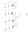
- FIGS. 6a to 6d illustrate two association rules used in a particular embodiment of this step 43:
- the cross referenced 61 represents the measured position (GNSS position) of a wireless seismic acquisition unit; the cross referenced 62 represents a topographic location; the circle referenced 63 represents an association area, the radius of the circle representing the association distance; the ellipse referenced 64 represents a computed association between a wireless seismic acquisition unit and a topographic location.
- Figure 6a illustrates the case of a single wireless seismic acquisition unit located in the association area of a topographic location. According to the first rule, a computed association between this wireless seismic acquisition unit and this topographic location is generated.
- Figure 6b illustrates the case of two wireless seismic acquisition units located in the association area of a topographic location. According to the first rule, a computed association between one of these wireless seismic acquisition units (the closest from the topographic position) and this topographic location is generated.
- Figure 6c illustrates the case of a wireless seismic acquisition unit located in two association areas (each of a different topographic location). According to the second rule, a computed association between this wireless seismic acquisition unit and one of these topographic locations (the closest from the wireless seismic acquisition unit) is generated.
- Figure 6d illustrates the case of a single wireless seismic acquisition unit located outside the association area of a topographic location. According to the first rule, no computed association is generated.
- step 44 the assigning device graphically presents to an operator, via its man-machine interface (e.g. on a screen), the associations resulting from step 43 of computing associations.
- step 45 the assigning device enables the operator, via its man-machine interface (e.g. screen and mouse, or touch screen), to validate or correct the associations graphically presented.
- man-machine interface e.g. screen and mouse, or touch screen
- step 46 the assigning device checks the computed associations (resulting from step 43). Particular embodiments of step 46 are detailed below, in relation with figures 7 and 8 .
- step 47 if at least one error is detected in step 46 of checking, the assigning device raises an alert via its man-machine interface and/or performs a correction operation. For example, GNSS erroneous positions are automatically detected and highlighted, and the operator (observer) can take appropriate corrective decisions (e.g. manually associate the wireless seismic acquisition unit to a topographic location or send someone on the field to associate the wireless seismic acquisition unit with a topographic location).
- steps 46 and 47 can be carried out immediately after steps 41 to 45, or later. In other words, steps 46 and 47 can be run on an assignment (resulting from steps 41 to 45) that has been made in the past (e.g. by reloading former events in a database of the assigning device). This allows to resurrect a former assignment and apply changes in former events.
- steps 46 and 47 are carried out on an assignment resulting from any prior art technique (e.g. the known three-step operation described above, in relation with figures 1 to 3 ).
- the assigning device checks if the measured position (GNSS position) of one of the wireless seismic acquisition units is an aberrant position. This may be indicative of an invalid GNSS position.
- the purpose of this test is to find aberrant positions, based on the relative positions of wireless seismic acquisition units and on the 3-sigma rule (normally applicable in the case of a Gaussian distribution). Although in the case of a seismic prospect a Gaussian distribution is not relevant, field trials revealed that the 3-sigma rule makes it possible to discard a reasonable amount of erroneous points.
- the assigning device checks if more than one wireless seismic acquisition unit is assigned to the same topographic location.
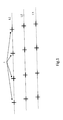
- the assigning device checks if, for a seismic line comprising a set of successive wireless seismic acquisition units in a determined order, the measured positions of this set of wireless seismic acquisition units are not consistent with the determined order.
- this alert is raised if the GNSS positions of the wireless seismic acquisition units in a same line do not progress in the same direction, as in the example of figure 7 .
- "116:153” is the identifier of a stake marking a topographic location. This identifier means that the associated wireless seismic acquisition unit is placed on the line “116" at the "153" rd position. As can be seen in figure 7 , the position of the wireless seismic acquisition unit assigned to stake "116:153" does not progress in the expected line order (the position goes "backwards" relative to the others).
- This problem may be indicative of a wrong wireless seismic acquisition unit position or a wireless seismic acquisition unit assigned to the wrong stake on the line.
- the assigning device checks if one of the wireless seismic acquisition units is spaced from its associated topographic location, by a distance greater than a determined threshold.
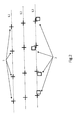
- the assigning device checks if, for two adjacent wireless seismic acquisition units of a seismic line comprising a set of successive wireless seismic acquisition units in a determined order, the measured positions of these two adjacent wireless seismic acquisition units are not consistent with their associated topographic locations.
- the GNSS positions do not match stakes (marking topographic positions) in the lines.
- This problem may be indicative of a wireless seismic acquisition unit assigned to a wrong stake (i.e. to a wrong topographic location) or wireless seismic acquisition unit marking performed in reverse line number order.
- the wireless seismic acquisition units assigned to the stakes 116:152 and 116:153 have been "swapped" (the vector direction between those stakes is inverted compared to the vector direction between the two wireless seismic acquisition units).
- Figure 9 shows the simplified structure of an assigning device 90 according to a particular embodiment of the invention.
- the assigning device is for example a central unit of a seismic system, or a personal computer of a mobile harvester.
- the assigning device 90 comprises a non-volatile memory 91 (e.g. a read-only memory (ROM) or a hard disk), a volatile memory 93 (e.g. a random access memory or RAM) and a processor 92.
- the non-volatile memory 91 is a non-transitory computer-readable carrier medium. It stores executable program code instructions, which are executed by the processor 92 in order to enable implementation of the method described above (method for automatically assigning wireless seismic acquisition units with topographic locations), in relation with figures 4 to 8 .
- the assigning device 90 receives (obtains) topographic locations 94a (see step 41 in figure 4 ) and measured positions (GNSS positions) 94b of the wireless seismic acquisition units (see step 42 in figure 4 ). It generates associations 95, each between one of the wireless seismic acquisition units and one of the topographic positions.
- the aforementioned program code instructions are transferred from the non-volatile memory 91 to the volatile memory 93 so as to be executed by the processor 92.
- the volatile memory 93 likewise includes registers for storing the variables and parameters required for this execution.
- the invention is not limited to a purely software-based implementation, in the form of computer program instructions, but that it can also be implemented in hardware form or any form combining a hardware portion and a software portion.
Landscapes
- Engineering & Computer Science (AREA)
- Life Sciences & Earth Sciences (AREA)
- Physics & Mathematics (AREA)
- Remote Sensing (AREA)
- General Physics & Mathematics (AREA)
- Geology (AREA)
- Environmental & Geological Engineering (AREA)
- General Life Sciences & Earth Sciences (AREA)
- Acoustics & Sound (AREA)
- Geophysics (AREA)
- Signal Processing (AREA)
- Computer Networks & Wireless Communication (AREA)
- Computer Security & Cryptography (AREA)
- Geophysics And Detection Of Objects (AREA)
- Position Fixing By Use Of Radio Waves (AREA)
- Radio Relay Systems (AREA)
- Mobile Radio Communication Systems (AREA)
- Rehabilitation Tools (AREA)
Abstract
Description
- The field of the invention is that of seismic data acquisition systems. To collect geophysical data, the principle of operation of these systems is as follows: for a given seismic survey, one or several seismic sources (explosives, falling weights, vibrators, air guns, etc.) are activated to propagate omnidirectional seismic wave trains; the wave trains reflected by the layers of the subsurface are detected by seismic sensors, which generate a signal characterizing the reflection of the waves on the geological interfaces of the subsurface.
- More specifically, the invention relates to a method for automatically assigning wireless seismic acquisition units to topographic positions.
- The invention can be applied notably to the oil prospecting industry using seismic method, but can be of interest for any other field implementing a seismic data acquisition network.
- Typically, a seismic data acquisition system comprises a network connected to a central unit.
- In a first known implementation, the network comprises a plurality of wired acquisition lines. Each wired acquisition line comprises nodes and concentrators, thus all seismic data can be received in the central unit in a real-time manner. The nodes are assembled in series along a telemetry cable and are each associated with at least one seismic sensor (in general, strings of seismic sensors). These nodes process signals transmitted by the seismic sensor(s) and generate data. The concentrators are assembled in series along the telemetry cable and are each associated with at least one of the nodes. Each concentrator receives the data generated by the node(s) with which it is associated. The sensors are either analog sensors or digital sensors. When analog sensors (also referred to as "geophones") are used, they are generally interconnected by cables to form clusters referred to as "strings of geophones". One or several of these strings of geophones (in series or in parallel) are connected to each node (in this case, a node is also referred to as FDU, for "Field Digitizing Unit") and this latter performs an analog to digital conversion of the signal from the groups of geophones and send these data to the central unit. When digital sensors are used (e.g. micro-machined accelerometers, also referred to as "MEMS-based digital accelerometer"), they are integrated in the nodes (in this case, a node is also referred to as DSU, for "Digital Sensor Unit"), which eliminates the geophone strings. Each node integrates one or several digital sensors.
- In a second known implementation, the network comprises wireless seismic acquisition units (also referred to as RAU, for "Remote Acquisition Units"). Each wireless seismic acquisition unit is independent and associated with (i.e. is connected to or integrates one or several functions of) one or several of aforesaid nodes. Each wireless seismic acquisition unit communicates wirelessly (directly or through one or several other wireless seismic acquisition units and/or through one or several of aforesaid concentrators) with the central unit and/or with a harvesting device (carried by an operator also referred to as "harvester") if a data harvesting strategy is implemented. The set of wireless seismic acquisition units could constitute a multi-hop wireless mesh network, allowing the wireless seismic acquisition units to exchange data, between them and with the central unit. Thus, each wireless seismic acquisition unit stores its own data (i.e. data obtained from the node(s) with which it is associated) and, eventually, also stores data received from one or several other wireless seismic acquisition units (i.e. data obtained from the node(s) associated with this or these other wireless seismic acquisition units). The sensors are either analog sensors or digital sensors. When analog sensors ("geophones") are used, each wireless seismic acquisition unit integrates for example one or a plurality of aforesaid nodes (as described for the first known implementation with geophones). When digital sensors are used, each wireless seismic acquisition unit is for example connected to a node which integrates one or several digital sensors (as described for the first known implementation with digital sensors).
- In the following description, we consider the case of the second known implementation, i.e. a network comprising wireless seismic acquisition units.
- In a seismic acquisition survey, the wireless seismic acquisition units are placed on the field at specific locations, known as "topographic locations". When implementing wireless seismic acquisition units, the following three steps are required (seismic data recording is starting when they are completed):
- a) The topographic locations have been defined by a geologist prior to the deployment of the wireless seismic acquisition units. The topographic locations have a precise location on the field (e.g. GPS coordinates or any other GNSS coordinates), which are recorded in a specific file (also called "SPS" file, for "Shell Processing Script" file). The topographic locations are generally computed at a central unit to draw a grid on the ground, along grid lines. In real conditions, there may be thousands of topographic locations on the field. They are indicated (staked out) by surveyors, on the ground, using a marker (stake, flag, paint on the ground, etc.).
Figure 1 illustrates an example oftopographic locations 1 on the ground, placed in a grid pattern comprising lines L1-L3. - b) During the seismic mission, the deployment of the wireless seismic acquisition units is performed at all marked topographic locations. In other words, each wireless seismic acquisition unit is installed on the ground, near a marked topographic location.
Figure 2 illustrates an example of wirelessseismic acquisition units 2 deployed near markedtopographic locations 1, along lines L1-L3. - c) Once wireless seismic acquisition units are deployed, another step is required for their identification on the field. It is necessary to know which wireless seismic acquisition unit is placed at which topographic location. This step is called "assignment step". An operator needs to walk along the lines where the wireless seismic acquisition units are placed (each line comprises an huge number of wireless seismic acquisition units, each unit being separated to another unit by a planned distance). Next, thanks to the help of an
external device 4, theoperator 3 records the associations each between one of the wirelessseismic acquisition units 2 on the ground and one of the topographic locations 1 (which is close to this wireless seismic acquisition unit). Most of external devices use RFID technology for the identification of units, and so require many people to sweep all the wireless seismic acquisition units with RFID readers.Figure 3 illustrates a manual assignment by anoperator 3 and itsexternal device 4, with the operator walking along a line L3 (as shown by the arrow referenced 5). - A drawback of this known operation in three steps is that walking along the lines and associating manually the wireless seismic acquisition units with their topographic locations consumes time for the human operators and needs the cost of an external device for each human operator. In other words, the known three-step operation is a huge constraint for deployment of wireless seismic acquisition units. Due to the high volume of wireless seismic acquisition units, it may take several days before starting seismic recording.
- Another drawback is that the human operators may make some mistake by manually entering the associations in their external devices.
- Yet another drawback is that the human operators are exposed to field hazards while walking on the survey location.
- The invention, in at least one embodiment, is aimed especially at overcoming these different drawbacks of the prior art.
- More specifically, it is a goal of at least one embodiment of the invention to provide a technique for assigning wireless seismic acquisition units to topographic positions, this technique simplifying the "assignment step" (compared with the step c) of the known three-step operation described above).
- It is another goal of at least one embodiment of the invention to provide a technique of this kind, not requiring human intervention on the field (nor external device a fortiori) and thus saving time, errors and avoiding field hazards.
- It is another goal of at least one embodiment of the invention to provide a technique of this kind, allows the reduction of cost, and/or reducing deployment time of the wireless seismic acquisition units.
- A particular embodiment of the invention proposes a method for automatically assigning wireless seismic acquisition units to topographic positions, each wireless seismic acquisition unit comprising a satellite navigation system receiver. Said method comprises the following steps, carried out by an assigning device:
- obtaining topographic locations at which the wireless seismic acquisition units are expected to be laid;
- obtaining measured positions of the wireless seismic acquisition units, corresponding to or derived from position information provided by the satellite navigation system receivers when the wireless seismic acquisition units are installed on the ground, each near one of the topographic locations; and
- computing associations, each between one of the wireless seismic acquisition units and one of the topographic positions, as a function of a comparison between the measured positions and the topographic locations.
- The general principle is that of taking advantage of the embedded satellite navigation system receiver (GNSS receiver, for "Global Navigation Satellite System" receiver) in wireless seismic acquisition units. This GNSS receiver is mainly used for time synchronization but it also gives either directly measured positions (GNSS positions) of the deployed wireless seismic acquisition units, or position information which can be used by the assigning device to obtain (using Differential GNSS post-processing) the measured positions (GNSS positions) of the deployed wireless seismic acquisition units. These two alternatives are detailed below. In both cases, the idea is to use the measured positions to find the topographic locations wireless seismic acquisition units have been assigned to.
- Doing so, there is no need of an external device, and no need for an operator to walk along the lines. We give more efficiency to the assignment phase (compared with the known third step of the aforesaid three-step operation) by automating the association between the wireless seismic acquisition units and their topographic locations on the field. So, we save the cost of an external device and the time of manually associating the wireless seismic acquisition units with the topographic locations, on the field. In other words, no human intervention on the field is necessary to associate the units with their topographic location, saving time, errors and avoiding field hazards.
- According to a particular feature, said step of computing associations is carried out using the following first rule: a given topographic position is associated to the closest wireless seismic acquisition unit, provided that a distance between said given topographic position and said closest wireless seismic acquisition unit is less than an association distance.
- This first rule is very easy implement. The GNSS positions of the wireless seismic acquisition units just need standard precision since the association is done within an association distance (i.e. an association range) that can exceed the GNSS range of error.
- According to a particular feature, said step of computing associations is carried out using the following second rule: if according to said first rule a given wireless seismic acquisition unit can be associated to several topographic positions, said given wireless seismic acquisition unit is associated to the closest topographic position.
- This second rule ensures that each wireless seismic acquisition unit is associated to only one topographic position.
- According to a particular feature, the method comprises the following step, carried out by the assigning device: graphically presenting to an operator, via a man-machine interface of said assigning device, the associations resulting from said step of computing associations.
- Thus the assigning device is very easy to use by the operator.
- According to a particular feature, the method comprises the following step, carried out by the assigning device: enabling the operator, via said man-machine interface, to validate or correct the associations graphically presented.
- Thus the operator can easily validate or correct the associations automatically carried out by the assigning device.
- According to a particular feature, the method comprises the following steps, carried out by the assigning device:
- checking the associations resulting from said step of computing associations; and
- if at least one error is detected in the step of checking, raising an alert via a man-machine interface of said assigning device, and/or performing a correction operation.
- Thus once an assignment has been made, it is possible to check it afterwards and to raise an alert and/or make some corrections. These supplemental steps can be run on the current assignment or on an assignment that has been made in the past (e.g. by reloading former events in a database of the assigning device). In other word, we can resurrect a former assignment and apply changes in former events.
- According to a first check, said step of checking comprises checking if the measured position of one of the wireless seismic acquisition units is an aberrant position.
- According to a second check, said step of checking comprises checking if more than one wireless seismic acquisition unit is assigned to the same topographic location.
- According to a third check, said step of checking comprises checking if one of the wireless seismic acquisition units is spaced from its associated topographic location, by a distance greater than a determined threshold.
- According to a fourth check, said step of checking comprises checking if, for a seismic line comprising a set of successive wireless seismic acquisition units in a determined order, the measured positions of said set of wireless seismic acquisition units are not consistent with said determined order.
- According to a fifth check, said step of checking comprises checking if, for two adjacent wireless seismic acquisition units of a seismic line comprising a set of successive wireless seismic acquisition units in a determined order, the measured positions of said two adjacent wireless seismic acquisition units are not consistent with their associated topographic locations.
- According to a particular feature, said assigning device is a central unit of a seismic system, or a personal computer of a mobile harvester.
- According to a first particular implementation, said step of obtaining measured positions comprises: obtaining the measured positions from the wireless seismic acquisition units, said measured positions being computed by the satellite navigation system receivers of the wireless seismic acquisition units.
- According to a second particular implementation, said step of obtaining measured positions comprises:
- obtaining first raw position data from the wireless seismic acquisition units, corresponding to position information provided by the satellite navigation system receivers when the wireless seismic acquisition units are installed on the ground, each near one of the topographic locations;
- obtaining second raw position data from at least one reference station, corresponding to position information provided by a satellite navigation system receiver comprised in said at least one reference station;
- computing said measured positions, as a function of said first raw position data and said second raw position data.
- In another embodiment, the invention pertains to a computer program product comprising program code instructions for implementing the above-mentioned method (in any of its different embodiments) when said program is executed on a computer or a processor.
- In another embodiment, the invention pertains to a non-transitory computer-readable carrier medium, storing a program which, when executed by a computer or a processor causes the computer or the processor to carry out the above-mentioned method (in any of its different embodiments).
- In another embodiment, the invention proposes an assigning device for automatically assigning wireless seismic acquisition units to topographic positions, each wireless seismic acquisition unit comprising a satellite navigation system receiver. Said assigning device comprises:
- means for obtaining topographic locations at which the wireless seismic acquisition units are expected to be laid;
- means for obtaining measured positions of the wireless seismic acquisition units, corresponding to or derived from position information provided by the satellite navigation system receivers when the wireless seismic acquisition units are installed on the ground, each near one of the topographic locations; and
- means for computing associations, each between one of the wireless seismic acquisition units and one of the topographic positions, as a function of a comparison between the measured positions and the topographic locations.
- Advantageously, the assigning device comprises means for implementing the steps it performs in the assigning method as described above, in any of its various embodiments.
- Other features and advantages of embodiments of the invention shall appear from the following description, given by way of an indicative and non-exhaustive examples and from the appended drawings, of which:
-
Figure 1 , already described with reference to the prior art, illustrates an example of topographic locations on the ground, placed in a grid pattern comprising lines (first step of the known three-step operation); -
Figure 2 , already described with reference to the prior art, illustrates an example of wireless seismic acquisition units deployed near marked topographic locations, along lines (second step of the known three-step operation); -
Figure 3 , already described with reference to the prior art, illustrates a manual assignment by an operator and its external device, with the operator walking along a line (third step of the known three-step operation); -
Figure 4 is a flowchart of a particular embodiment of the method according to the invention; -
Figure 5 provides a schematic illustration of a particular embodiment ofstep 42 infigure 4 (obtaining measured positions of the wireless seismic acquisition units); -
Figures 6a to 6d illustrate association rules used in a particular embodiment ofstep 43 infigure 4 (computing associations between the wireless seismic acquisition units and the topographic locations); -
Figure 7 illustrates a first example of error detected instep 46 infigure 4 (checking the computed associations); -
Figure 8 illustrates a second example of error detected instep 46 infigure 4 (checking the computed associations); -
Figure 9 shows the simplified structure of an assigning device according to a particular embodiment of the invention; and -
Figure 10 is a particular embodiment ofstep 42 infigure 4 (obtaining measured positions). - In all of the figures of the present document, identical elements and steps are designated by the same numerical reference sign.
- Referring now to the flowchart of
figure 4 , we present a particular embodiment of the method according to the invention. When executed by an assigning device (seefigure 9 described below), this method automatically assigns wireless seismic acquisition units to topographic positions. - In
step 41, the assigning device obtains topographic locations at which the wireless seismic acquisition units are expected to be laid. - As already detailed above (see
figure 1 and the first step of the known three-step operation), the topographic locations are defined by a geologist prior to the deployment of the wireless seismic acquisition units. The topographic locations have a precise location on the field (GNSS coordinates), which are recorded in a specific file (SPS file). In real conditions, there may be thousands of topographic locations on the field. On the ground, they are indicated (by surveyors) using a marker (stake, flag, paint on the ground, etc.). - In
step 42, the assigning device obtains measured positions (GNSS positions) of the wireless seismic acquisition units. The idea is to use the GNSS receiver already embedded in the wireless seismic acquisition unit and mainly used for time synchronization. In other words, the measured positions are provided by GNSS receivers embedded in the wireless seismic acquisition units, when the wireless seismic acquisition units are installed on the ground, each near one of the topographic locations. Each wireless seismic acquisition unit comprises a GNSS receiver. GNSS receiver refers to a receiver compatible with any existing or future satellite navigation system (GPS, GALILEO, GLONASS, COMPASS, IRNSS,...). - In other words, once the wireless seismic acquisition units have been deployed on the ground (i.e. after the second step of the known three-step operation, see
figure 2 ), their GNSS receivers compute the GNSS positions. These GNSS positions are then retrieved, for example along with the QC (Quality Control) and SOH (State of Health, e.g. the battery level of each wireless seismic acquisition unit) information, during the QC/SOH retrieving phase. As shown infigure 5 , this is usually done by aradio receiver 6 which may be fixed or mobile (carried by an operator or embedded on a vehicle) and which receives the GNSS positions information transmitted by means of a radio transmitter embedded in each wirelessseismic acquisition unit 2. -
Figure 10 shows an alternative embodiment ofstep 42. Here, the measured positions (GNSS positions) are not computed directly by the GNSS receivers, and therefore not provided by the wireless seismic acquisition units. Instead, the assigning device carries out the following steps: - step 101: obtaining first raw position data from the wireless seismic acquisition units, corresponding to position information provided by the GNSS receivers when the wireless seismic acquisition units are installed on the ground, each near one of the topographic locations;
- step 102: obtaining second raw position data from at least one GNSS reference station, corresponding to position information provided by a GNSS receiver comprised in said at least one GNSS reference station;
- step 103: computing the measured positions, as a function of the first raw position data and said second raw position data, with a differential GNSS post-processing algorithm.
- In this alternative embodiment, the GNSS reference station is a static GNSS receiver whose exact position is known. This GNSS reference station may be a high end dedicated GNSS RTK ("Real Time Kinematic") receiver or the GNSS receiver from one the wireless seismic acquisition units provided that the unit position is accurately known. The distance between the reference station and all wireless seismic acquisition units shall not exceed a predetermined distance (e.g. 20km) for best performances.
- This alternative embodiment operates for example as follows: before or during seismic data recording, GNSS receivers are activated in all wireless seismic acquisition units and in the reference station(s). At the same time, the GNSS receiver of the reference station and the GNSS receivers of the wireless seismic acquisition units, track satellites from the corresponding constellation. GNSS raw data from all the aforesaid GNSS receivers (i.e. those comprised in the wireless seismic acquisition units and in the reference station(s)) are recorded. Usually GNSS raw data periodicity is 1 second, but other data rates may be configured. For each GNSS satellite, these raw data include code pseudo-range measurements, carrier-phase measurements, Doppler frequency measurements as well as navigation messages broadcast by the satellite. Once enough GNSS raw data are recorded (typically 15 minutes) data recording is stopped. GNSS raw data from the wireless seismic acquisition units and the reference station(s) are then retrieved. GNSS raw data format may be proprietary format or standard format, e.g. as RINEX/BINEX. In the assigning device (e.g. the central unit), a differential GNSS post-processing algorithm (software and/or hardware implementation) is used to compute the measured positions of all wireless seismic acquisition units, as a function of GNSS raw data from the reference station(s) and GNSS raw data from each wireless seismic acquisition unit.
- A well known differential GNSS post-processing software is for example "RTKLIB" which is an Open Source Program Package for GNSS Positioning (http://www.rtklib.com). RTKLIB consists of a portable program library and several APs (application programs) utilizing the library. It supports various positioning modes with GNSS for both real-time and post-processing.
- The general principle of differential GNSS positioning (real-time or post-processing) is based on the fact that positioning error is the same at a GNSS reference station and at a GNSS rover receiver (GNSS receiver moving on the field) provided the distance between them is no more than a predetermined distance (e.g. 10km to 40km). Accuracy is dependent on environment, raw data recording time and distance to reference station. Knowing the accurate position of the reference station, the differential GNSS positioning algorithms are able to calculate the accurate position of the GNSS rover receiver. To reach centimeter-level accuracy, the GNSS reference station and the GNSS rover receiver must be able to do simultaneously code and carrier-phase observations, generally called raw data. These observations are recorded by the GNSS reference station and the GNSS rover receiver, in order to be processed later. Post-processing allows to fix the carrier-phase ambiguity to each satellite and determine location of the GNSS rover receiver relative to the GNSS reference station with high accuracy.
- In
step 43, the assigning device computes associations, each between one of the wirelessseismic acquisition units 2 and one of thetopographic positions 1, as a function of a comparison between the measured positions (GNSS positions) and the topographic locations. -
Figures 6a to 6d illustrate two association rules used in a particular embodiment of this step 43: - first rule: a given topographic position is associated to the closest wireless seismic acquisition unit, provided that a distance between the given topographic position and the closest wireless seismic acquisition unit is less than an association distance;
- second rule: if according to the first rule a given wireless seismic acquisition unit can be associated to several topographic positions, the given wireless seismic acquisition unit is associated to the closest topographic position.
- In the legend: the cross referenced 61 represents the measured position (GNSS position) of a wireless seismic acquisition unit; the cross referenced 62 represents a topographic location; the circle referenced 63 represents an association area, the radius of the circle representing the association distance; the ellipse referenced 64 represents a computed association between a wireless seismic acquisition unit and a topographic location.
-
Figure 6a illustrates the case of a single wireless seismic acquisition unit located in the association area of a topographic location. According to the first rule, a computed association between this wireless seismic acquisition unit and this topographic location is generated. -
Figure 6b illustrates the case of two wireless seismic acquisition units located in the association area of a topographic location. According to the first rule, a computed association between one of these wireless seismic acquisition units (the closest from the topographic position) and this topographic location is generated. -
Figure 6c illustrates the case of a wireless seismic acquisition unit located in two association areas (each of a different topographic location). According to the second rule, a computed association between this wireless seismic acquisition unit and one of these topographic locations (the closest from the wireless seismic acquisition unit) is generated. -
Figure 6d illustrates the case of a single wireless seismic acquisition unit located outside the association area of a topographic location. According to the first rule, no computed association is generated. - In
step 44, the assigning device graphically presents to an operator, via its man-machine interface (e.g. on a screen), the associations resulting fromstep 43 of computing associations. - In
step 45, the assigning device enables the operator, via its man-machine interface (e.g. screen and mouse, or touch screen), to validate or correct the associations graphically presented. - In
step 46, the assigning device checks the computed associations (resulting from step 43). Particular embodiments ofstep 46 are detailed below, in relation withfigures 7 and 8 . - In
step 47, if at least one error is detected instep 46 of checking, the assigning device raises an alert via its man-machine interface and/or performs a correction operation. For example, GNSS erroneous positions are automatically detected and highlighted, and the operator (observer) can take appropriate corrective decisions (e.g. manually associate the wireless seismic acquisition unit to a topographic location or send someone on the field to associate the wireless seismic acquisition unit with a topographic location). - Thus once an assignment has been made, it is possible to check it afterwards and to raise an alert and/or make some corrections. It must be noted that
steps steps 41 to 45, or later. In other words, steps 46 and 47 can be run on an assignment (resulting fromsteps 41 to 45) that has been made in the past (e.g. by reloading former events in a database of the assigning device). This allows to resurrect a former assignment and apply changes in former events. - In an alternative embodiment, steps 46 and 47 are carried out on an assignment resulting from any prior art technique (e.g. the known three-step operation described above, in relation with
figures 1 to 3 ). - We detail now particular embodiments of the checking
step 46 infigure 4 (also referred to as "geometry check"). - The assigning device checks if the measured position (GNSS position) of one of the wireless seismic acquisition units is an aberrant position. This may be indicative of an invalid GNSS position.
- The following algorithm is performed:
- for each wireless seismic acquisition unit, projecting its GNSS positions, i.e. its latitude and longitude, in a planar coordinate system (according to the same projection model for all wireless seismic acquisition units). The result is a couple of planar coordinates x and y;
- computing the average of the x (Ex, expected value of x) and the average of the y (Ey, expected value of y), over all x,y of all wireless seismic acquisition units;
- computing sigmax, the average of the deviations from Ex, and sigmay, the average of the deviations from Ey, over all x,y of all wireless seismic acquisition units;
- for each wireless seismic acquisition unit:
- o testing if the following first condition is satisfied: the x coordinate is comprised between Ex - 3 sigmax and Ex + 3 sigmax;
- o testing if the following second condition is satisfied: the y coordinate is comprised between Ey - 3 sigmay and Ey + 3 sigmay;
- o if one of the first and second conditions is not satisfied, the wireless seismic acquisition unit is reported as "far from prospect".
- The purpose of this test is to find aberrant positions, based on the relative positions of wireless seismic acquisition units and on the 3-sigma rule (normally applicable in the case of a Gaussian distribution). Although in the case of a seismic prospect a Gaussian distribution is not relevant, field trials revealed that the 3-sigma rule makes it possible to discard a reasonable amount of erroneous points.
- The assigning device checks if more than one wireless seismic acquisition unit is assigned to the same topographic location.
- The assigning device checks if, for a seismic line comprising a set of successive wireless seismic acquisition units in a determined order, the measured positions of this set of wireless seismic acquisition units are not consistent with the determined order.
- In other words, this alert is raised if the GNSS positions of the wireless seismic acquisition units in a same line do not progress in the same direction, as in the example of
figure 7 . In this example, "116:153" is the identifier of a stake marking a topographic location. This identifier means that the associated wireless seismic acquisition unit is placed on the line "116" at the "153"rd position. As can be seen infigure 7 , the position of the wireless seismic acquisition unit assigned to stake "116:153" does not progress in the expected line order (the position goes "backwards" relative to the others). - This problem may be indicative of a wrong wireless seismic acquisition unit position or a wireless seismic acquisition unit assigned to the wrong stake on the line.
- The following mathematical checks are performed, for each wireless seismic acquisition unit assigned to the same line, in increasing stake order (assuming Unit1 is a wireless seismic acquisition unit, Unit2 is the next one in increasing stake order, Unit3 is the next one):
- computing U, the vector linking the measure positions (GNSS positions) of Unit1 and Unit2 (from Unit1 to Unit2),
- computing V, the vector linking the measure positions (GNSS positions) of Unit2 and Unit3 (from Unit2 to Unit3), and
- reporting Unit3 in "Wrong line order", if the scalar product U.V is negative.
- Same as check 1) above.
- Same as check 2) above.
- The assigning device checks if one of the wireless seismic acquisition units is spaced from its associated topographic location, by a distance greater than a determined threshold.
- The assigning device checks if, for two adjacent wireless seismic acquisition units of a seismic line comprising a set of successive wireless seismic acquisition units in a determined order, the measured positions of these two adjacent wireless seismic acquisition units are not consistent with their associated topographic locations.
- In other words, the GNSS positions do not match stakes (marking topographic positions) in the lines. This problem may be indicative of a wireless seismic acquisition unit assigned to a wrong stake (i.e. to a wrong topographic location) or wireless seismic acquisition unit marking performed in reverse line number order.
- In the example of
figure 8 , the wireless seismic acquisition units assigned to the stakes 116:152 and 116:153 have been "swapped" (the vector direction between those stakes is inverted compared to the vector direction between the two wireless seismic acquisition units). - The following mathematical checks are performed, for each stake which has a wireless seismic acquisition unit assigned to it in the line, in increasing point order:
- Rec1 is a stake, Rec2 is the next stake, in increasing stake order,
- Unit1 is the wireless seismic acquisition unit assigned to Rec1, Unit2 is the wireless seismic acquisition unit assigned to Rec2,
- computing U, the vector linking the topographic locations of Rec1 and Rec2 (from Rec1 to Rec2),
- computing V, the vector linking the measure positions (GNSS positions) of Unit1 and Unit2 (from Unit1 to Unit2), and
- reporting Unit1 and Unit2 in "wrong line order", if the scalar product U.V is negative.
-
Figure 9 shows the simplified structure of an assigningdevice 90 according to a particular embodiment of the invention. The assigning device is for example a central unit of a seismic system, or a personal computer of a mobile harvester. - The assigning
device 90 comprises a non-volatile memory 91 (e.g. a read-only memory (ROM) or a hard disk), a volatile memory 93 (e.g. a random access memory or RAM) and aprocessor 92. Thenon-volatile memory 91 is a non-transitory computer-readable carrier medium. It stores executable program code instructions, which are executed by theprocessor 92 in order to enable implementation of the method described above (method for automatically assigning wireless seismic acquisition units with topographic locations), in relation withfigures 4 to 8 . - The assigning
device 90 receives (obtains)topographic locations 94a (seestep 41 infigure 4 ) and measured positions (GNSS positions) 94b of the wireless seismic acquisition units (seestep 42 infigure 4 ). It generatesassociations 95, each between one of the wireless seismic acquisition units and one of the topographic positions. - Upon initialization, the aforementioned program code instructions are transferred from the
non-volatile memory 91 to thevolatile memory 93 so as to be executed by theprocessor 92. Thevolatile memory 93 likewise includes registers for storing the variables and parameters required for this execution. - All the steps of the above assignment method can be implemented equally well:
- by the execution of a set of program code instructions executed by a reprogrammable computing machine such as a PC type apparatus, a DSP (digital signal processor) or a microcontroller. This program code instructions can be stored in a non-transitory computer-readable carrier medium that is detachable (for example a floppy disk, a CD-ROM or a DVD-ROM) or non-detachable; or
- by a dedicated machine or component, such as an FPGA (Field Programmable Gate Array), an ASIC (Application-Specific Integrated Circuit) or any dedicated hardware component.
- In other words, the invention is not limited to a purely software-based implementation, in the form of computer program instructions, but that it can also be implemented in hardware form or any form combining a hardware portion and a software portion.
- Although the present disclosure has been described with reference to one or more examples, workers skilled in the art will recognize that changes may be made in form and detail without departing from the scope of the disclosure and/or the appended claims.
Claims (17)
- Method for automatically assigning wireless seismic acquisition units to topographic positions, each wireless seismic acquisition unit comprising a satellite navigation system receiver, characterized in that said method comprises the following steps, carried out by an assigning device:- obtaining (41) topographic locations at which the wireless seismic acquisition units are expected to be laid;- obtaining (42) measured positions of the wireless seismic acquisition units, corresponding to or derived from position information provided by the satellite navigation system receivers when the wireless seismic acquisition units are installed on the ground, each near one of the topographic locations; and- computing (43) associations, each between one of the wireless seismic acquisition units and one of the topographic positions, as a function of a comparison between the measured positions and the topographic locations.
- Method according to claim 1, characterized in that said step of computing associations is carried out using the following first rule: a given topographic position is associated to the closest wireless seismic acquisition unit, provided that a distance between said given topographic position and said closest wireless seismic acquisition unit is less than an association distance.
- Method according to claim 2, characterized in that said step of computing associations is carried out using the following second rule: if according to said first rule a given wireless seismic acquisition unit can be associated to several topographic positions, said given wireless seismic acquisition unit is associated to the closest topographic position.
- Method according to any one of the claims 1 to 3, characterized in that it comprises the following step, carried out by the assigning device:- graphically presenting (44) to an operator, via a man-machine interface of said assigning device, the associations resulting from said step of computing associations.
- Method according to claim 4, characterized in that it comprises the following step, carried out by the assigning device:- enabling (45) the operator, via said man-machine interface, to validate or correct the associations graphically presented.
- Method according to any one of the claims 1 to 5, characterized in that it comprises the following steps, carried out by the assigning device:- checking (46) the associations resulting from said step of computing associations; and- if at least one error is detected in the step of checking, raising (47) an alert via a man-machine interface of said assigning device, and/or performing (47) a correction operation.
- Method according to claim 6, characterized in that said step of checking comprises checking if the measured position of one of the wireless seismic acquisition units is an aberrant position.
- Method according to claim 6, characterized in that said step of checking comprises checking if more than one wireless seismic acquisition unit is assigned to the same topographic location.
- Method according to claim 6, characterized in that said step of checking comprises checking if one of the wireless seismic acquisition units is spaced from its associated topographic location, by a distance greater than a determined threshold.
- Method according to claim 6, characterized in that said step of checking comprises checking if, for a seismic line comprising a set of successive wireless seismic acquisition units in a determined order, the measured positions of said set of wireless seismic acquisition units are not consistent with said determined order.
- Method according to claim 6, characterized in that said step of checking comprises checking if, for two adjacent wireless seismic acquisition units of a seismic line comprising a set of successive wireless seismic acquisition units in a determined order, the measured positions of said two adjacent wireless seismic acquisition units are not consistent with their associated topographic locations.
- Method according to any one of the claims 1 to 11, characterized in that said assigning device is a central unit of a seismic system, or a personal computer of a mobile harvester.
- Method according to any one of the claims 1 to 12, characterized in that said step of obtaining measured positions comprises:- obtaining the measured positions from the wireless seismic acquisition units, said measured positions being computed by the satellite navigation system receivers of the wireless seismic acquisition units.
- Method according to any one of the claims 1 to 12, characterized in that said step of obtaining (42) measured positions comprises:- obtaining (101) first raw position data from the wireless seismic acquisition units, corresponding to position information provided by the satellite navigation system receivers when the wireless seismic acquisition units are installed on the ground, each near one of the topographic locations;- obtaining (102) second raw position data from at least one reference station, corresponding to position information provided by a satellite navigation system receiver comprised in said at least one reference station;- computing (103) said measured positions, as a function of said first raw position data and said second raw position data.
- Computer program product characterized in that it comprises program code instructions for implementing the method according to at least one of the claims 1 to 14, when said program is executed on a computer or a processor.
- A non-transitory computer-readable carrier medium (91) storing a computer program product according to claim 15.
- Assigning device (90) for automatically assigning wireless seismic acquisition units to topographic positions, each wireless seismic acquisition unit comprising a satellite navigation system receiver, characterized in that said assigning device comprises:- means for obtaining topographic locations at which the wireless seismic acquisition units are expected to be laid;- means for obtaining measured positions of the wireless seismic acquisition units, corresponding to or derived from position information provided by the satellite navigation system receivers when the wireless seismic acquisition units are installed on the ground, each near one of the topographic locations; and- means for computing associations, each between one of the wireless seismic acquisition units and one of the topographic positions, as a function of a comparison between the measured positions and the topographic locations.
Priority Applications (2)
| Application Number | Priority Date | Filing Date | Title |
|---|---|---|---|
| PL14175694T PL2919038T3 (en) | 2014-03-12 | 2014-07-03 | Method for automatically assigning wireless seismic acquisition units to topographic positions |
| HRP20192163TT HRP20192163T1 (en) | 2014-03-12 | 2019-11-29 | Method for automatically assigning wireless seismic acquisition units to topographic positions |
Applications Claiming Priority (2)
| Application Number | Priority Date | Filing Date | Title |
|---|---|---|---|
| US201461951882P | 2014-03-12 | 2014-03-12 | |
| US201461951898P | 2014-03-12 | 2014-03-12 |
Publications (3)
| Publication Number | Publication Date |
|---|---|
| EP2919038A2 true EP2919038A2 (en) | 2015-09-16 |
| EP2919038A3 EP2919038A3 (en) | 2015-10-21 |
| EP2919038B1 EP2919038B1 (en) | 2019-09-04 |
Family
ID=51059344
Family Applications (1)
| Application Number | Title | Priority Date | Filing Date |
|---|---|---|---|
| EP14175694.0A Active EP2919038B1 (en) | 2014-03-12 | 2014-07-03 | Method for automatically assigning wireless seismic acquisition units to topographic positions |
Country Status (8)
| Country | Link |
|---|---|
| US (1) | US9810799B2 (en) |
| EP (1) | EP2919038B1 (en) |
| CN (1) | CN104914460B (en) |
| HR (1) | HRP20192163T1 (en) |
| HU (1) | HUE047224T2 (en) |
| MX (1) | MX346863B (en) |
| PL (1) | PL2919038T3 (en) |
| RU (1) | RU2684491C2 (en) |
Cited By (1)
| Publication number | Priority date | Publication date | Assignee | Title |
|---|---|---|---|---|
| CN110554430A (en) * | 2019-09-10 | 2019-12-10 | 山东知微智成电子科技有限公司 | AD conversion and data storage system and method for wireless seismic exploration data acquisition node |
Family Cites Families (10)
| Publication number | Priority date | Publication date | Assignee | Title |
|---|---|---|---|---|
| FR2671197A1 (en) * | 1990-12-28 | 1992-07-03 | Inst Francais Du Petrole | METHOD AND DEVICE FOR SIMPLIFYING THE LOCATION OF AN UNDERGROUND AREA IN THE CONTEXT OF A SEISMIC EXPLORATION. |
| US20040105533A1 (en) * | 1998-08-07 | 2004-06-03 | Input/Output, Inc. | Single station wireless seismic data acquisition method and apparatus |
| US6560565B2 (en) * | 1999-04-30 | 2003-05-06 | Veritas Dgc Inc. | Satellite-based seismic mobile information and control system |
| US7773457B2 (en) * | 2005-10-07 | 2010-08-10 | Wireless Seismic | Wireless exploration seismic system |
| US7224642B1 (en) * | 2006-01-26 | 2007-05-29 | Tran Bao Q | Wireless sensor data processing systems |
| US8605546B2 (en) * | 2006-09-29 | 2013-12-10 | Inova Ltd. | Seismic data acquisition systems and method utilizing a wireline repeater unit |
| US8577660B2 (en) * | 2008-01-23 | 2013-11-05 | Schlumberger Technology Corporation | Three-dimensional mechanical earth modeling |
| US8614928B2 (en) * | 2009-12-31 | 2013-12-24 | Wireless Seismic, Inc. | Wireless data acquisition system and method using self-initializing wireless modules |
| CN101988968A (en) * | 2010-09-02 | 2011-03-23 | 成都林海电子有限责任公司 | Wireless network-based earthquake monitoring system and implementation method thereof |
| CN103605155B (en) * | 2013-12-05 | 2016-04-06 | 石家庄经济学院 | High precision wireless MANET seismic acquisition unit |
-
2014
- 2014-07-03 PL PL14175694T patent/PL2919038T3/en unknown
- 2014-07-03 EP EP14175694.0A patent/EP2919038B1/en active Active
- 2014-07-03 HU HUE14175694A patent/HUE047224T2/en unknown
- 2014-07-15 US US14/332,025 patent/US9810799B2/en active Active
-
2015
- 2015-03-11 RU RU2015108586A patent/RU2684491C2/en active
- 2015-03-11 CN CN201510105660.0A patent/CN104914460B/en active Active
- 2015-03-11 MX MX2015003135A patent/MX346863B/en active IP Right Grant
-
2019
- 2019-11-29 HR HRP20192163TT patent/HRP20192163T1/en unknown
Non-Patent Citations (1)
| Title |
|---|
| None |
Cited By (1)
| Publication number | Priority date | Publication date | Assignee | Title |
|---|---|---|---|---|
| CN110554430A (en) * | 2019-09-10 | 2019-12-10 | 山东知微智成电子科技有限公司 | AD conversion and data storage system and method for wireless seismic exploration data acquisition node |
Also Published As
| Publication number | Publication date |
|---|---|
| MX2015003135A (en) | 2015-10-14 |
| MX346863B (en) | 2017-04-04 |
| HUE047224T2 (en) | 2020-04-28 |
| RU2684491C2 (en) | 2019-04-09 |
| EP2919038A3 (en) | 2015-10-21 |
| RU2015108586A3 (en) | 2018-10-08 |
| EP2919038B1 (en) | 2019-09-04 |
| RU2015108586A (en) | 2016-09-27 |
| US20150260863A1 (en) | 2015-09-17 |
| US9810799B2 (en) | 2017-11-07 |
| PL2919038T3 (en) | 2020-05-18 |
| HRP20192163T1 (en) | 2020-03-06 |
| CN104914460B (en) | 2019-12-27 |
| CN104914460A (en) | 2015-09-16 |
Similar Documents
| Publication | Publication Date | Title |
|---|---|---|
| CN108253969B (en) | Method for calculating flight line-of-sight link coverage range of unmanned aerial vehicle | |
| El-Mowafy | Precise real-time positioning using Network RTK | |
| CN102401658A (en) | Systems and methods for computing vertical position | |
| CN104062687A (en) | Air ground integrated geomagnetic field combined observation method and system | |
| CN103339627A (en) | Evaluating surface data | |
| JP2015175803A (en) | radiation distribution measurement system | |
| Mulakala | Measurement accuracy of the DJI Phantom 4 RTK & photogrammetry | |
| KR100496814B1 (en) | Method for obtaining road coordinates information and producing digital map using gps measurement | |
| KR100510835B1 (en) | Method for constituting geographic information system applied digital map using real time measuring systems | |
| US11656364B2 (en) | Real-time correlation of sensed position data with terrestrial features | |
| EP2919038B1 (en) | Method for automatically assigning wireless seismic acquisition units to topographic positions | |
| CA2883065C (en) | Method for automatically assigning wireless seismic acquisition units to topographic positions | |
| KR100529511B1 (en) | Method for producing digital map by road boundary measuring and constituting geographic information system using the same | |
| Encarnacion et al. | RTKLIB-based GPS localization for multipath mitigation in ITS applications | |
| Gond et al. | Accuracy assessment of relative GPS as a function of distance and duration for CORS network | |
| Metzler et al. | Low-cost drone system for analyzing elevation | |
| US11895561B2 (en) | Method of and system for localizing a device within an environment | |
| Løvås | Increasing the accuracy of positioning in mobile mapping systems-a method supported by simultaneous localization and mapping | |
| Kersel et al. | On Hedgehogs and Marvelous Minds: A New Technology for Point Data Collection? | |
| Hill et al. | On Hedgehogs and Marvelous Minds: A New Technology for Point Data Collection? | |
| Běloch et al. | Optimizing Mobile Laser Scanning Accuracy for Urban Applications: A Comparison by Strategy of Different Measured Ground Points | |
| KR100496811B1 (en) | Method for obtaining height information of buildings and producing digital map using gps measurement | |
| KR100510834B1 (en) | Method for producing digital map by applying facilities information of each survey day and constituting geographic information system using the same | |
| Iyiola et al. | Integrity Check on Ground Control Points Using NIGNET’s Continuously Operating Reference Stations | |
| WO2023089302A1 (en) | Identifying events in distributed acoustic sensing data |
Legal Events
| Date | Code | Title | Description |
|---|---|---|---|
| PUAI | Public reference made under article 153(3) epc to a published international application that has entered the european phase |
Free format text: ORIGINAL CODE: 0009012 |
|
| AK | Designated contracting states |
Kind code of ref document: A2 Designated state(s): AL AT BE BG CH CY CZ DE DK EE ES FI FR GB GR HR HU IE IS IT LI LT LU LV MC MK MT NL NO PL PT RO RS SE SI SK SM TR |
|
| AX | Request for extension of the european patent |
Extension state: BA ME |
|
| PUAL | Search report despatched |
Free format text: ORIGINAL CODE: 0009013 |
|
| AK | Designated contracting states |
Kind code of ref document: A3 Designated state(s): AL AT BE BG CH CY CZ DE DK EE ES FI FR GB GR HR HU IE IS IT LI LT LU LV MC MK MT NL NO PL PT RO RS SE SI SK SM TR |
|
| AX | Request for extension of the european patent |
Extension state: BA ME |
|
| RIC1 | Information provided on ipc code assigned before grant |
Ipc: G01V 1/16 20060101ALI20150915BHEP Ipc: G01V 1/00 20060101AFI20150915BHEP Ipc: G01V 1/22 20060101ALI20150915BHEP |
|
| 17P | Request for examination filed |
Effective date: 20160419 |
|
| RBV | Designated contracting states (corrected) |
Designated state(s): AL AT BE BG CH CY CZ DE DK EE ES FI FR GB GR HR HU IE IS IT LI LT LU LV MC MK MT NL NO PL PT RO RS SE SI SK SM TR |
|
| STAA | Information on the status of an ep patent application or granted ep patent |
Free format text: STATUS: EXAMINATION IS IN PROGRESS |
|
| 17Q | First examination report despatched |
Effective date: 20180315 |
|
| GRAP | Despatch of communication of intention to grant a patent |
Free format text: ORIGINAL CODE: EPIDOSNIGR1 |
|
| STAA | Information on the status of an ep patent application or granted ep patent |
Free format text: STATUS: GRANT OF PATENT IS INTENDED |
|
| INTG | Intention to grant announced |
Effective date: 20190415 |
|
| GRAS | Grant fee paid |
Free format text: ORIGINAL CODE: EPIDOSNIGR3 |
|
| GRAA | (expected) grant |
Free format text: ORIGINAL CODE: 0009210 |
|
| STAA | Information on the status of an ep patent application or granted ep patent |
Free format text: STATUS: THE PATENT HAS BEEN GRANTED |
|
| AK | Designated contracting states |
Kind code of ref document: B1 Designated state(s): AL AT BE BG CH CY CZ DE DK EE ES FI FR GB GR HR HU IE IS IT LI LT LU LV MC MK MT NL NO PL PT RO RS SE SI SK SM TR |
|
| REG | Reference to a national code |
Ref country code: GB Ref legal event code: FG4D |
|
| REG | Reference to a national code |
Ref country code: CH Ref legal event code: EP |
|
| REG | Reference to a national code |
Ref country code: AT Ref legal event code: REF Ref document number: 1176145 Country of ref document: AT Kind code of ref document: T Effective date: 20190915 |
|
| REG | Reference to a national code |
Ref country code: DE Ref legal event code: R096 Ref document number: 602014052851 Country of ref document: DE |
|
| REG | Reference to a national code |
Ref country code: IE Ref legal event code: FG4D |
|
| REG | Reference to a national code |
Ref country code: HR Ref legal event code: TUEP Ref document number: P20192163T Country of ref document: HR |
|
| REG | Reference to a national code |
Ref country code: NL Ref legal event code: FP |
|
| REG | Reference to a national code |
Ref country code: LT Ref legal event code: MG4D |
|
| PG25 | Lapsed in a contracting state [announced via postgrant information from national office to epo] |
Ref country code: NO Free format text: LAPSE BECAUSE OF FAILURE TO SUBMIT A TRANSLATION OF THE DESCRIPTION OR TO PAY THE FEE WITHIN THE PRESCRIBED TIME-LIMIT Effective date: 20191204 Ref country code: BG Free format text: LAPSE BECAUSE OF FAILURE TO SUBMIT A TRANSLATION OF THE DESCRIPTION OR TO PAY THE FEE WITHIN THE PRESCRIBED TIME-LIMIT Effective date: 20191204 Ref country code: SE Free format text: LAPSE BECAUSE OF FAILURE TO SUBMIT A TRANSLATION OF THE DESCRIPTION OR TO PAY THE FEE WITHIN THE PRESCRIBED TIME-LIMIT Effective date: 20190904 Ref country code: LT Free format text: LAPSE BECAUSE OF FAILURE TO SUBMIT A TRANSLATION OF THE DESCRIPTION OR TO PAY THE FEE WITHIN THE PRESCRIBED TIME-LIMIT Effective date: 20190904 Ref country code: FI Free format text: LAPSE BECAUSE OF FAILURE TO SUBMIT A TRANSLATION OF THE DESCRIPTION OR TO PAY THE FEE WITHIN THE PRESCRIBED TIME-LIMIT Effective date: 20190904 |
|
| PG25 | Lapsed in a contracting state [announced via postgrant information from national office to epo] |
Ref country code: GR Free format text: LAPSE BECAUSE OF FAILURE TO SUBMIT A TRANSLATION OF THE DESCRIPTION OR TO PAY THE FEE WITHIN THE PRESCRIBED TIME-LIMIT Effective date: 20191205 Ref country code: RS Free format text: LAPSE BECAUSE OF FAILURE TO SUBMIT A TRANSLATION OF THE DESCRIPTION OR TO PAY THE FEE WITHIN THE PRESCRIBED TIME-LIMIT Effective date: 20190904 Ref country code: LV Free format text: LAPSE BECAUSE OF FAILURE TO SUBMIT A TRANSLATION OF THE DESCRIPTION OR TO PAY THE FEE WITHIN THE PRESCRIBED TIME-LIMIT Effective date: 20190904 Ref country code: AL Free format text: LAPSE BECAUSE OF FAILURE TO SUBMIT A TRANSLATION OF THE DESCRIPTION OR TO PAY THE FEE WITHIN THE PRESCRIBED TIME-LIMIT Effective date: 20190904 Ref country code: ES Free format text: LAPSE BECAUSE OF FAILURE TO SUBMIT A TRANSLATION OF THE DESCRIPTION OR TO PAY THE FEE WITHIN THE PRESCRIBED TIME-LIMIT Effective date: 20190904 |
|
| REG | Reference to a national code |
Ref country code: HR Ref legal event code: T1PR Ref document number: P20192163 Country of ref document: HR |
|
| REG | Reference to a national code |
Ref country code: AT Ref legal event code: MK05 Ref document number: 1176145 Country of ref document: AT Kind code of ref document: T Effective date: 20190904 |
|
| REG | Reference to a national code |
Ref country code: HU Ref legal event code: AG4A Ref document number: E047224 Country of ref document: HU |
|
| PG25 | Lapsed in a contracting state [announced via postgrant information from national office to epo] |
Ref country code: PT Free format text: LAPSE BECAUSE OF FAILURE TO SUBMIT A TRANSLATION OF THE DESCRIPTION OR TO PAY THE FEE WITHIN THE PRESCRIBED TIME-LIMIT Effective date: 20200106 Ref country code: IT Free format text: LAPSE BECAUSE OF FAILURE TO SUBMIT A TRANSLATION OF THE DESCRIPTION OR TO PAY THE FEE WITHIN THE PRESCRIBED TIME-LIMIT Effective date: 20190904 Ref country code: RO Free format text: LAPSE BECAUSE OF FAILURE TO SUBMIT A TRANSLATION OF THE DESCRIPTION OR TO PAY THE FEE WITHIN THE PRESCRIBED TIME-LIMIT Effective date: 20190904 Ref country code: AT Free format text: LAPSE BECAUSE OF FAILURE TO SUBMIT A TRANSLATION OF THE DESCRIPTION OR TO PAY THE FEE WITHIN THE PRESCRIBED TIME-LIMIT Effective date: 20190904 Ref country code: EE Free format text: LAPSE BECAUSE OF FAILURE TO SUBMIT A TRANSLATION OF THE DESCRIPTION OR TO PAY THE FEE WITHIN THE PRESCRIBED TIME-LIMIT Effective date: 20190904 |
|
| PG25 | Lapsed in a contracting state [announced via postgrant information from national office to epo] |
Ref country code: CZ Free format text: LAPSE BECAUSE OF FAILURE TO SUBMIT A TRANSLATION OF THE DESCRIPTION OR TO PAY THE FEE WITHIN THE PRESCRIBED TIME-LIMIT Effective date: 20190904 Ref country code: IS Free format text: LAPSE BECAUSE OF FAILURE TO SUBMIT A TRANSLATION OF THE DESCRIPTION OR TO PAY THE FEE WITHIN THE PRESCRIBED TIME-LIMIT Effective date: 20200224 Ref country code: SK Free format text: LAPSE BECAUSE OF FAILURE TO SUBMIT A TRANSLATION OF THE DESCRIPTION OR TO PAY THE FEE WITHIN THE PRESCRIBED TIME-LIMIT Effective date: 20190904 Ref country code: SM Free format text: LAPSE BECAUSE OF FAILURE TO SUBMIT A TRANSLATION OF THE DESCRIPTION OR TO PAY THE FEE WITHIN THE PRESCRIBED TIME-LIMIT Effective date: 20190904 |
|
| REG | Reference to a national code |
Ref country code: DE Ref legal event code: R097 Ref document number: 602014052851 Country of ref document: DE |
|
| PLBE | No opposition filed within time limit |
Free format text: ORIGINAL CODE: 0009261 |
|
| REG | Reference to a national code |
Ref country code: HR Ref legal event code: ODRP Ref document number: P20192163 Country of ref document: HR Payment date: 20200630 Year of fee payment: 7 |
|
| STAA | Information on the status of an ep patent application or granted ep patent |
Free format text: STATUS: NO OPPOSITION FILED WITHIN TIME LIMIT |
|
| PG2D | Information on lapse in contracting state deleted |
Ref country code: IS |
|
| PG25 | Lapsed in a contracting state [announced via postgrant information from national office to epo] |
Ref country code: IS Free format text: LAPSE BECAUSE OF FAILURE TO SUBMIT A TRANSLATION OF THE DESCRIPTION OR TO PAY THE FEE WITHIN THE PRESCRIBED TIME-LIMIT Effective date: 20200105 Ref country code: DK Free format text: LAPSE BECAUSE OF FAILURE TO SUBMIT A TRANSLATION OF THE DESCRIPTION OR TO PAY THE FEE WITHIN THE PRESCRIBED TIME-LIMIT Effective date: 20190904 |
|
| 26N | No opposition filed |
Effective date: 20200605 |
|
| PG25 | Lapsed in a contracting state [announced via postgrant information from national office to epo] |
Ref country code: SI Free format text: LAPSE BECAUSE OF FAILURE TO SUBMIT A TRANSLATION OF THE DESCRIPTION OR TO PAY THE FEE WITHIN THE PRESCRIBED TIME-LIMIT Effective date: 20190904 |
|
| PG25 | Lapsed in a contracting state [announced via postgrant information from national office to epo] |
Ref country code: MC Free format text: LAPSE BECAUSE OF FAILURE TO SUBMIT A TRANSLATION OF THE DESCRIPTION OR TO PAY THE FEE WITHIN THE PRESCRIBED TIME-LIMIT Effective date: 20190904 |
|
| REG | Reference to a national code |
Ref country code: CH Ref legal event code: PL |
|
| GBPC | Gb: european patent ceased through non-payment of renewal fee |
Effective date: 20200703 |
|
| REG | Reference to a national code |
Ref country code: BE Ref legal event code: MM Effective date: 20200731 |
|
| PG25 | Lapsed in a contracting state [announced via postgrant information from national office to epo] |
Ref country code: LU Free format text: LAPSE BECAUSE OF NON-PAYMENT OF DUE FEES Effective date: 20200703 Ref country code: CH Free format text: LAPSE BECAUSE OF NON-PAYMENT OF DUE FEES Effective date: 20200731 Ref country code: IE Free format text: LAPSE BECAUSE OF NON-PAYMENT OF DUE FEES Effective date: 20200703 Ref country code: GB Free format text: LAPSE BECAUSE OF NON-PAYMENT OF DUE FEES Effective date: 20200703 Ref country code: LI Free format text: LAPSE BECAUSE OF NON-PAYMENT OF DUE FEES Effective date: 20200731 |
|
| PG25 | Lapsed in a contracting state [announced via postgrant information from national office to epo] |
Ref country code: BE Free format text: LAPSE BECAUSE OF NON-PAYMENT OF DUE FEES Effective date: 20200731 |
|
| REG | Reference to a national code |
Ref country code: HR Ref legal event code: ODRP Ref document number: P20192163 Country of ref document: HR Payment date: 20210625 Year of fee payment: 8 |
|
| PG25 | Lapsed in a contracting state [announced via postgrant information from national office to epo] |
Ref country code: TR Free format text: LAPSE BECAUSE OF FAILURE TO SUBMIT A TRANSLATION OF THE DESCRIPTION OR TO PAY THE FEE WITHIN THE PRESCRIBED TIME-LIMIT Effective date: 20190904 Ref country code: MT Free format text: LAPSE BECAUSE OF FAILURE TO SUBMIT A TRANSLATION OF THE DESCRIPTION OR TO PAY THE FEE WITHIN THE PRESCRIBED TIME-LIMIT Effective date: 20190904 Ref country code: CY Free format text: LAPSE BECAUSE OF FAILURE TO SUBMIT A TRANSLATION OF THE DESCRIPTION OR TO PAY THE FEE WITHIN THE PRESCRIBED TIME-LIMIT Effective date: 20190904 |
|
| PG25 | Lapsed in a contracting state [announced via postgrant information from national office to epo] |
Ref country code: MK Free format text: LAPSE BECAUSE OF FAILURE TO SUBMIT A TRANSLATION OF THE DESCRIPTION OR TO PAY THE FEE WITHIN THE PRESCRIBED TIME-LIMIT Effective date: 20190904 |
|
| REG | Reference to a national code |
Ref country code: HR Ref legal event code: ODRP Ref document number: P20192163 Country of ref document: HR Payment date: 20220628 Year of fee payment: 9 |
|
| REG | Reference to a national code |
Ref country code: HR Ref legal event code: ODRP Ref document number: P20192163 Country of ref document: HR Payment date: 20230628 Year of fee payment: 10 |
|
| PGFP | Annual fee paid to national office [announced via postgrant information from national office to epo] |
Ref country code: PL Payment date: 20230623 Year of fee payment: 10 Ref country code: NL Payment date: 20230719 Year of fee payment: 10 Ref country code: HR Payment date: 20230628 Year of fee payment: 10 |
|
| PGFP | Annual fee paid to national office [announced via postgrant information from national office to epo] |
Ref country code: HU Payment date: 20230721 Year of fee payment: 10 Ref country code: FR Payment date: 20230726 Year of fee payment: 10 Ref country code: DE Payment date: 20230719 Year of fee payment: 10 |