EP2916583B1 - Terminal device, base station device, reception method and transmission method - Google Patents
Terminal device, base station device, reception method and transmission method Download PDFInfo
- Publication number
- EP2916583B1 EP2916583B1 EP13852204.0A EP13852204A EP2916583B1 EP 2916583 B1 EP2916583 B1 EP 2916583B1 EP 13852204 A EP13852204 A EP 13852204A EP 2916583 B1 EP2916583 B1 EP 2916583B1
- Authority
- EP
- European Patent Office
- Prior art keywords
- subframe
- phich
- configuration
- terminal apparatus
- terminal
- Prior art date
- Legal status (The legal status is an assumption and is not a legal conclusion. Google has not performed a legal analysis and makes no representation as to the accuracy of the status listed.)
- Active
Links
- 238000000034 method Methods 0.000 title claims description 55
- 230000005540 biological transmission Effects 0.000 title claims description 25
- 230000004044 response Effects 0.000 claims description 97
- 230000006978 adaptation Effects 0.000 claims description 5
- 101150096310 SIB1 gene Proteins 0.000 claims 4
- 230000000875 corresponding effect Effects 0.000 description 76
- 101000741965 Homo sapiens Inactive tyrosine-protein kinase PRAG1 Proteins 0.000 description 53
- 102100038659 Inactive tyrosine-protein kinase PRAG1 Human genes 0.000 description 53
- 238000004891 communication Methods 0.000 description 37
- 238000010586 diagram Methods 0.000 description 17
- 230000003044 adaptive effect Effects 0.000 description 14
- 238000012937 correction Methods 0.000 description 13
- 230000008859 change Effects 0.000 description 12
- 230000011664 signaling Effects 0.000 description 9
- 238000001514 detection method Methods 0.000 description 7
- 108010003272 Hyaluronate lyase Proteins 0.000 description 6
- 125000004122 cyclic group Chemical group 0.000 description 6
- 238000005516 engineering process Methods 0.000 description 6
- 238000012545 processing Methods 0.000 description 6
- 230000008569 process Effects 0.000 description 5
- 101001139126 Homo sapiens Krueppel-like factor 6 Proteins 0.000 description 4
- 101000710013 Homo sapiens Reversion-inducing cysteine-rich protein with Kazal motifs Proteins 0.000 description 4
- 101150071746 Pbsn gene Proteins 0.000 description 4
- 238000006243 chemical reaction Methods 0.000 description 4
- 230000000694 effects Effects 0.000 description 4
- 101001109518 Homo sapiens N-acetylneuraminate lyase Proteins 0.000 description 3
- 102100022686 N-acetylneuraminate lyase Human genes 0.000 description 3
- 239000000284 extract Substances 0.000 description 3
- 230000010354 integration Effects 0.000 description 3
- 101000760620 Homo sapiens Cell adhesion molecule 1 Proteins 0.000 description 2
- 101000911772 Homo sapiens Hsc70-interacting protein Proteins 0.000 description 2
- 101000661807 Homo sapiens Suppressor of tumorigenicity 14 protein Proteins 0.000 description 2
- 230000002776 aggregation Effects 0.000 description 2
- 238000004220 aggregation Methods 0.000 description 2
- 230000008901 benefit Effects 0.000 description 2
- 230000002596 correlated effect Effects 0.000 description 2
- 230000001419 dependent effect Effects 0.000 description 2
- 108090000237 interleukin-24 Proteins 0.000 description 2
- 238000013507 mapping Methods 0.000 description 2
- 239000000203 mixture Substances 0.000 description 2
- 238000010295 mobile communication Methods 0.000 description 2
- 238000003860 storage Methods 0.000 description 2
- 102100027715 4-hydroxy-2-oxoglutarate aldolase, mitochondrial Human genes 0.000 description 1
- 101001081225 Homo sapiens 4-hydroxy-2-oxoglutarate aldolase, mitochondrial Proteins 0.000 description 1
- 101000604027 Homo sapiens Nuclear protein localization protein 4 homolog Proteins 0.000 description 1
- 101000974007 Homo sapiens Nucleosome assembly protein 1-like 3 Proteins 0.000 description 1
- 101001099181 Homo sapiens TATA-binding protein-associated factor 2N Proteins 0.000 description 1
- 102100038438 Nuclear protein localization protein 4 homolog Human genes 0.000 description 1
- 102100038917 TATA-binding protein-associated factor 2N Human genes 0.000 description 1
- 238000004364 calculation method Methods 0.000 description 1
- 239000000969 carrier Substances 0.000 description 1
- 238000004519 manufacturing process Methods 0.000 description 1
- 230000009467 reduction Effects 0.000 description 1
- 239000004065 semiconductor Substances 0.000 description 1
- 238000001228 spectrum Methods 0.000 description 1
Images


Classifications
-
- H—ELECTRICITY
- H04—ELECTRIC COMMUNICATION TECHNIQUE
- H04J—MULTIPLEX COMMUNICATION
- H04J11/00—Orthogonal multiplex systems, e.g. using WALSH codes
- H04J11/0023—Interference mitigation or co-ordination
- H04J11/0026—Interference mitigation or co-ordination of multi-user interference
- H04J11/003—Interference mitigation or co-ordination of multi-user interference at the transmitter
-
- H—ELECTRICITY
- H04—ELECTRIC COMMUNICATION TECHNIQUE
- H04W—WIRELESS COMMUNICATION NETWORKS
- H04W72/00—Local resource management
- H04W72/04—Wireless resource allocation
- H04W72/044—Wireless resource allocation based on the type of the allocated resource
- H04W72/0446—Resources in time domain, e.g. slots or frames
-
- H—ELECTRICITY
- H04—ELECTRIC COMMUNICATION TECHNIQUE
- H04J—MULTIPLEX COMMUNICATION
- H04J3/00—Time-division multiplex systems
- H04J3/16—Time-division multiplex systems in which the time allocation to individual channels within a transmission cycle is variable, e.g. to accommodate varying complexity of signals, to vary number of channels transmitted
- H04J3/1694—Allocation of channels in TDM/TDMA networks, e.g. distributed multiplexers
-
- H—ELECTRICITY
- H04—ELECTRIC COMMUNICATION TECHNIQUE
- H04L—TRANSMISSION OF DIGITAL INFORMATION, e.g. TELEGRAPHIC COMMUNICATION
- H04L5/00—Arrangements affording multiple use of the transmission path
- H04L5/003—Arrangements for allocating sub-channels of the transmission path
- H04L5/0053—Allocation of signaling, i.e. of overhead other than pilot signals
- H04L5/0055—Physical resource allocation for ACK/NACK
-
- H—ELECTRICITY
- H04—ELECTRIC COMMUNICATION TECHNIQUE
- H04L—TRANSMISSION OF DIGITAL INFORMATION, e.g. TELEGRAPHIC COMMUNICATION
- H04L5/00—Arrangements affording multiple use of the transmission path
- H04L5/003—Arrangements for allocating sub-channels of the transmission path
- H04L5/0058—Allocation criteria
- H04L5/0073—Allocation arrangements that take into account other cell interferences
-
- H—ELECTRICITY
- H04—ELECTRIC COMMUNICATION TECHNIQUE
- H04L—TRANSMISSION OF DIGITAL INFORMATION, e.g. TELEGRAPHIC COMMUNICATION
- H04L5/00—Arrangements affording multiple use of the transmission path
- H04L5/14—Two-way operation using the same type of signal, i.e. duplex
-
- H—ELECTRICITY
- H04—ELECTRIC COMMUNICATION TECHNIQUE
- H04L—TRANSMISSION OF DIGITAL INFORMATION, e.g. TELEGRAPHIC COMMUNICATION
- H04L5/00—Arrangements affording multiple use of the transmission path
- H04L5/14—Two-way operation using the same type of signal, i.e. duplex
- H04L5/1469—Two-way operation using the same type of signal, i.e. duplex using time-sharing
-
- H—ELECTRICITY
- H04—ELECTRIC COMMUNICATION TECHNIQUE
- H04W—WIRELESS COMMUNICATION NETWORKS
- H04W72/00—Local resource management
- H04W72/20—Control channels or signalling for resource management
- H04W72/23—Control channels or signalling for resource management in the downlink direction of a wireless link, i.e. towards a terminal
-
- H—ELECTRICITY
- H04—ELECTRIC COMMUNICATION TECHNIQUE
- H04W—WIRELESS COMMUNICATION NETWORKS
- H04W72/00—Local resource management
- H04W72/50—Allocation or scheduling criteria for wireless resources
- H04W72/54—Allocation or scheduling criteria for wireless resources based on quality criteria
- H04W72/541—Allocation or scheduling criteria for wireless resources based on quality criteria using the level of interference
-
- H—ELECTRICITY
- H04—ELECTRIC COMMUNICATION TECHNIQUE
- H04L—TRANSMISSION OF DIGITAL INFORMATION, e.g. TELEGRAPHIC COMMUNICATION
- H04L1/00—Arrangements for detecting or preventing errors in the information received
- H04L1/12—Arrangements for detecting or preventing errors in the information received by using return channel
- H04L1/16—Arrangements for detecting or preventing errors in the information received by using return channel in which the return channel carries supervisory signals, e.g. repetition request signals
- H04L1/18—Automatic repetition systems, e.g. Van Duuren systems
- H04L1/1829—Arrangements specially adapted for the receiver end
- H04L1/1861—Physical mapping arrangements
Definitions
- the present invention relates to a terminal apparatus, a base station apparatus, a reception method and a transmission method.
- 3GPP LTE adopts OFDMA (Orthogonal Frequency Division Multiple Access) as a downlink communication scheme.
- a base station which may also be called “eNB” transmits a synchronization signal (Synchronization Channel: SCH) and broadcast signal (Broadcast Channel: BCH) using predetermined communication resources.
- a terminal (which may also be called “UE”) captures SCH and thereby secures synchronization with the base station. The terminal then reads BCH information and thereby acquires a parameter specific to the base station (e.g., frequency bandwidth) (see NPLs 1,2 and 3).
- the terminal After completion of the acquisition of the parameter specific to the base station, the terminal sends a connection request to the base station and thereby establishes communication with the base station.
- the base station transmits control information to the terminal with which communication has been established via a downlink control channel such as PDCCH (Physical Downlink Control Channel) as appropriate.
- PDCCH Physical Downlink Control Channel
- the terminal then performs "blind detection" of a plurality of pieces of control information (which may also be called “downlink control information (DCI)”) included in the received PDCCH signal. That is, the control information includes a CRC (Cyclic Redundancy Check) portion and this CRC portion is masked with a terminal ID of the transmission target terminal by the base station. Therefore, the terminal cannot determine whether or not the received control information is control information intended for the terminal until the terminal demasks the CRC portion with the terminal ID of the terminal itself. When the demasking result shows that CRC calculation is OK, it is determined in this blind detection that the control information is intended for the terminal itself.
- the downlink control information includes DL (downlink) assignment indicating assignment information of downlink data and UL (uplink) grant indicating assignment information of uplink data, for example.
- UL grant which is assignment information of uplink data is transmitted to the terminal by PDCCH.
- a UL grant indicates resource assignment within a target subframe which is the fourth subframe from the subframe in which the UL grant is transmitted.
- a UL grant indicates resource assignment within a target subframe which is the fourth or after the fourth subframe from the subframe in which the UL grant is transmitted. This will be described more specifically using FIG. 1 .
- a downlink component carrier which may also be called “downlink CC (Component Carrier)”
- an uplink component carrier which may also be called “uplink CC”
- the TDD system realizes downlink communication and uplink communication by switching between downlink and uplink in a time-division manner.
- a downlink component carrier can also be expressed as "downlink communication timing in a component carrier.”
- An uplink component carrier can also be expressed as "uplink communication timing in a component carrier.”
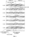
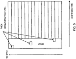
- Switching between the downlink component carrier and the uplink component carrier is performed based on a UL-DL configuration as shown in FIG. 1 .
- the UL-DL configuration is indicated to the terminal by a broadcast signal called "SIB1 (System Information Block Type 1)" (SIB1 indication), the value thereof is the same throughout the entire system and the value is not expected to be changed frequently.
- SIB1 System Information Block Type 1
- timings in units of subframes are configured for downlink communication (DL: Downlink) and uplink communication (UL: Uplink) per frame (10 msec).
- DL Downlink
- UL Uplink
- the UL-DL configuration allows for building a communication system that can flexibly respond to demand for more throughput for either downlink communication or uplink communication by changing a subframe ratio between downlink communication and uplink communication.
- FIG. 1 illustrates UL-DL configurations (Config#0 to 6) with different subframe ratios between downlink communication and uplink communication.
- a downlink communication subframe is represented by "D”
- an uplink communication subframe is represented by “U”
- a special subframe is represented by "S.”
- the special subframe is a subframe when a downlink communication subframe is switched to an uplink communication subframe.
- downlink data communication may also be performed as in the case of a downlink communication subframe.
- PUSCH Physical Uplink Shared Channel
- PUSCH Physical Uplink Shared Channel
- Uplink retransmission control supports non-adaptive retransmission in which retransmission data is assigned to the same frequency resource as the one to which uplink data is assigned at the time of the last transmission and adaptive retransmission in which retransmission data can be assigned to a frequency resource different from the one to which uplink data was assigned at the last transmission (e.g., see NPL 4).
- non-adaptive retransmission only PHICH (Physical Hybrid ARQ Indicator CHannel) for transmitting an ACK/NACK signal (response signal), in response to uplink data, to the terminal is used as a channel for a retransmission control signal.
- the base station When requesting the terminal to perform retransmission, the base station transmits a NACK to the terminal using PHICH and transmits an ACK using PHICH when not requesting the terminal to perform retransmission.
- non-adaptive retransmission since the base station can designate retransmission using only PHICH, non-adaptive retransmission has an advantage that the overhead of a control signal transmitted over downlink necessary to designate retransmission is small.
- PHICH is indicated to the terminal using a resource within a target subframe which is the fourth subframe from the subframe in which uplink data is transmitted.
- PHICH is indicated to the terminal using a resource within a target subframe which is the fourth or after the fourth subframe from the subframe in which uplink data is transmitted. This will be described more specifically using FIG 1 . As shown by a broken line arrow (PUSCH-PHICH timing) in FIG.
- a subframe to which ACK/NACK (PHICH) in response to uplink data (PUSCH) is assigned is a downlink communication subframe or special subframe 4 or more subframes after a subframe in which the uplink data is indicated and is uniquely defined as shown in FIG. 1 .
- the base station transmits an ACK using PHICH while designating retransmission and a retransmission resource using UL grant for indicating resource assignment information.
- UL grant includes a bit called "NDI (New Data Indicator)" and this bit is binary having 0 or 1.
- the terminal compares an NDI of the received UL grant this time with an NDI of the last UL grant in the same retransmission process (HARQ (Hybrid ARQ) process), determines that new data has been assigned when there is a change in the NDI or determines that retransmission data has been assigned when there is no change in the NDI.
- HARQ Hybrid ARQ
- adaptive retransmission allows the amount of resources and MCS (Modulation and Coding Scheme) to be changed according to a required SINR (Signal-to-Interference and Noise power Ratio) of retransmission data
- SINR Signal-to-Interference and Noise power Ratio
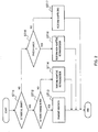
- FIG. 2 shows an example of a procedure for UL retransmission control in the terminal.
- the terminal determines whether or not there is UL grant.
- ST11: YES When there is UL grant (ST11: YES), the flow proceeds to ST12 and when there is no UL grant (ST11: NO), the flow proceeds to ST15.
- the terminal compares the NDI of UL grant this time with the NDI of the last UL grant in the same retransmission process and determines whether or not there is any change in the NDI.
- ST12: YES When there is a change in the NDI (ST12: YES), the flow proceeds to ST13 and when there is no change in the NDI (ST12: NO), the flow proceeds to ST14.
- the terminal transmits new data to the base station in ST13 and transmits retransmission data to the base station through adaptive retransmission in ST14.
- the terminal determines whether or not PHICH is NACK.
- PHICH is NACK (ST15: YES)
- the flow proceeds to ST16
- PHICH is ACK (ST15: NO)
- the flow proceeds to ST17.
- the terminal transmits retransmission data to the base station through non-adaptive retransmission, and in ST17, suspending is applied, so that the terminal suspends retransmission control.
- one RB (Resource Block) is made up of 12 subcarriers ⁇ 0.5 msec and a unit combining two RBs on the time domain is called "RB pair.” Therefore, the RB pair is made up of 12 subcarriers ⁇ 1 msec. When the RB pair represents a block of 12 subcarriers on the frequency domain, the RB pair may be simply called "RB.” In addition, a unit of 1 subcarrier ⁇ 1 OFDM symbol is called "1 RE (Resource Element)." 1 REG (Resource Element Group) is made up of 4 REs.
- ACK/NACK (1 bit) is subjected to three-time repetition.
- the number of PHICHs is one of ⁇ 1/6, 1/2, 1, 2 ⁇ times the number of RBs and is indicated by PBCH (Physical Broadcast Channel).
- the 8 PHICHs arranged on 3 REGs are called a PHICH group and expressed as "number of PHICH groups (that is, the number of resources) N group PHICH is 8."
- the number of PHICH groups N group PHICH takes the same value in all subframes.
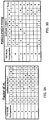
- a factor (m i ) of number of PHICH groups is defined in each UL-DL configuration and each downlink communication subframe or special subframe.
- the factor of number of PHICH groups is always 1 irrespective of subframes.
- FIG. 3B illustrates the number of subframes before a PHICH received by the terminal in subframe #n is associated with a PUSCH transmitted by the terminal. Blanks in FIG. 3B indicate that there are no PHICHs.
- PHICH in subframe #1 of Config#0 is associated with PUSCH transmitted in subframe #7 which is 4 subframes earlier (see FIG. 1 ).
- PHICH in subframe #0 of Config#0 is associated with PUSCHs transmitted in subframe #3 which is 7 subframes earlier and in subframe #4 which is 6 subframes earlier respectively. That is, in subframe #0 of Config#0, the terminal receives PHICHs corresponding to two PUSCHs.
- PHICH resources twice as many resources for PHICH (hereinafter referred to as "PHICH resources") as those in subframe #1 of Config#0 are required, and therefore factor m i of number of PHICH groups is considered to be 2 (see FIG. 3A ).
- two PHICHs intended for the same terminal received in the same subframe are distinguished by parameter I PHICH .
- I PHICH is always 0.
- a PHICH resource is represented by a combination ⁇ n group PHICH , n seq PHICH ⁇ of an index of the total number of PHICH resources n group PHICH and an index of orthogonal sequence n seq PHICH.
- the index of the total number of PHICH resources n group PHICH and the index of orthogonal sequence n seq PHICH are expressed by following equations 1 and 2 respectively.
- n PHICH group I PRB _ RA + n DMRS mod N PHICH group + I PHICH N PHICH group [2]
- n PHICH seq ⁇ I PRB _ RA / N PHICH group ⁇ + n DMRS mod 2 N SF PHICH
- N PHICH SF is a spreading factor (SF) that varies depending on the length of a CP (Cyclic Prefix).
- I PRB_RA is a minimum value of a PRB (Physical RB) index to which PUSCH corresponding to PHICH is assigned.
- I PRB_RA is a minimum value of a PRB (Physical RB) index to which PUSCH corresponding to PHICH is assigned.
- I PRB_RA is a value obtained by adding 1 to the minimum value of the PRB index to which PUSCH corresponding to PHICH is assigned.
- n DMRS is a cyclic shift value of DMRS (Demodulation Reference Signal) included in UL grant that indicates PUSCH corresponding to PHICH. Since I PRB_RA and n DMRS depend on assignment of UL grant and PUSCH, a PHICH resource can be said to be implicitly indicated (implicit signalling) based on the assignment of UL grant and PUSCH.
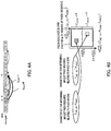
- the determined PHICH resource is divided for every value of I PHICH . For example, in subframe #0 of Config#0, PHICH corresponding to PUSCH 7 subframes earlier and PHICH corresponding to PUSCH 6 subframes earlier are designed such that the PHICH resources do not conflict with each other.
- FIG. 4A there are two PHICHs intended for the same terminal in subframe #0 of Config#0.
- I PRB_RA and n DMRS are uniquely defined by the assignment of PUSCH in subframe #3 and UL grant indicating the PUSCH. As shown in FIG.
- I PRB_RA and n DMRS are uniquely defined by the assignment of PUSCH in subframe #4 and UL grant indicating the PUSCH (hereinafter described as I PRB_RA ' and n DMRS ' for distinction).
- PHICH depends on a cell ID. Therefore, it is difficult to control interference of PHICH with other cells and PHICH may interfere with PDCCH and/or CRS (Cell-specific Reference Signal) in other cells. All of 3 REGs making up PHICH may be arranged on OFDM symbol #0 (not shown) or 3 REGs may be arranged one for each of OFDM symbols #0, #1 and #2 as shown in FIG. 4 . Information indicating which PHICH arrangement is used is indicated to the terminal using a broadcast signal.
- the number of OFDM symbols (1 to 3) occupied by PDCCH is determined based on the value of CFI (Control Format Indicator) indicated by PCFICH (Physical Control Format Indicator Channel) arranged on OFDM symbol #0.
- CFI Control Format Indicator
- PCFICH Physical Control Format Indicator Channel
- the terminal when detecting PDCCH, the terminal performs blind detection on some resources in resource regions except resources occupied by PCFICH, PHICH and reference signals (hereinafter may also be referred to as "PDCCH resources") of resource regions corresponding to the number of OFDM symbols indicated by CFI from OFDM symbol #0.
- TDD eIMTA enhanced for DL-UL Interference Management and Traffic Adaptation
- dynamic TDD enhanced for DL-UL Interference Management and Traffic Adaptation
- exemplary purposes of TDD eIMTA include provision of a service that meets the needs of users by flexible changes of a UL/DL ratio or reduction in power consumption at a base station by increasing the UL ratio in a time zone when traffic load is low.
- Method (1) is to change the least frequent UL-DL configuration.
- Method (1) is suitable for a case where the purpose is to reduce power consumption at a base station by increasing the UL ratio, for example, in a time zone when traffic load is low (e.g., midnight or early morning).
- Method (4) is to change the most frequent UL-DL configuration change.
- the number of terminals connected is smaller in a small cell such as a pico cell than in a large cell such as a macro cell.
- UL/DL traffic in the entire pico cell is determined depending on the level of UL/DL traffic in a small number of terminals connected to the pico cell. For this reason, UL/DL traffic in the pico cell fluctuates drastically with time.
- method (4) is suitable for a case where UL-DL configuration is changed to follow a time fluctuation of UL/DL traffic in a small cell such as a pico cell.
- Method (2) and method (3) are positioned between method (1) and method (4) and suitable for a case where UL-DL configuration is changed with medium frequency.
- non-TDD eIMTA terminal a terminal using an SIB1-indicated UL-DL configuration
- legacy terminal a terminal that supports TDD eIMTA using UL-DL configuration which is different from the SIB1-indicated UL-DL configuration
- TDD eIMTA terminal a terminal using an SIB1-indicated UL-DL configuration
- the LTE system and LTE-A system define PUSCH timing corresponding to PHICH for each UL-DL configuration (timing relating to uplink retransmission control).
- factor (m i ) of the number of PHICH groups is defined in association with PHICH reception timing in a terminal. Therefore, the timing relating to uplink retransmission control and a factor of the number of PHICH groups may differ between a legacy terminal using SIB1-indicated UL-DL configuration and a TDD eIMTA terminal using UL-DL configuration which is different from the SIB1- indicated UL-DL configuration.
- FIG. 6B illustrates resources of PHICH corresponding to the legacy terminal and the TDD eIMTA terminal within a PHICH resource region.
- a parameter set (I PRB_RA , n DMRS ) for PUSCH assignment in subframe #3 in the legacy terminal (Config#0) and UL grant indicating the PUSCH is identical to a parameter set (I PRB_RA , n DMRS ) for PUSCH assignment in subframe #4 in the TDD eIMTA terminal (Config#6) and UL grant indicating the PUSCH.
- PUSCH of the legacy terminal in subframe #3 and PUSCH of the TDD eIMTA terminal in subframe #4 have cyclic shift values corresponding to the same leading PRB index and the same DMRS.
- I PHICH 0 is defined for PHICH corresponding to each PUSCH. Therefore, as shown in FIG. 6B , PHICH resources for PUSCH transmission in subframe #3 for the legacy terminal (Config#0) and PHICH resources for PUSCH transmission for the TDD eIMTA terminal (Config#6) in subframe #4 conflict with each other.
- FIG. 7B illustrates resources of PHICH for the legacy terminal and the TDD eIMTA terminal within the PHICH resource region.
- a parameter set (I PRB_RA , n DMRS ) corresponding to PUSCH assignment of subframe #4 in the legacy terminal (Config#6) and UL grant indicating the PUSCH is identical to a parameter set (I PRB_RA , n DMRS ) corresponding to PUSCH assignment of subframe #3 in the TDD eIMTA terminal (Config#0) and UL grant indicating the PUSCH.
- PUSCH of the legacy terminal in subframe #4 and PUSCH of the TDD eIMTA terminal in subframe #3 have cyclic shift values corresponding to the same leading PRB index and the same DMRS.
- I PHICH 0 is defined for PHICH corresponding to each PUSCH. Therefore, as shown in FIG. 7B , PHICH resources for PUSCH transmission in subframe #4 in the legacy terminal (Config#6) and PHICH resources for PUSCH transmission in subframe #3 in the TDD eIMTA terminal (Config#0) conflict with each other.
- WO 2007/091831 discloses a method for transmitting radio resources in a mobile communication system.
- the method includes receiving a random access channel (RACH) preamble from a plurality of UEs and transmitting response information associated with the received preambles over a common channel wherein the plurality UEs can access the common channel and receive corresponding information.
- RACH random access channel
- the eNode-B does not pre-allocate uplink radio resources required for re-transmission and performs allocation of radio resources for a first transmission of HARQ.
- the eNode-B allocates the radio resources required for the re-transmission with the NACK signal. If re-transmission is not required, the method can reduce an amount of wasted radio resources.
- EP2 159 939 A1 discloses a base station device which includes: a random access identification information storage that stores random access identification information and mobile station device identification information correlated with the random access identification information, the random access identification information being allocated by the base station device to the mobile station device, and the mobile station device identification information identifying the mobile station device; a random access receiver that receives random access identification information transmitted by the mobile station device performing random access; a scheduler that, if the random access identification information received is stored in the random access identification information storage while being correlated with the mobile station device identification information, determines whether to transmit random access response information that is a response to the random access corresponding to the random access identification information received by using the mobile station device identification information, or by using identification information having not been allocated to a specific mobile station device, the identification information being allocated for transmitting the response to the random access; and a transmitter that allocates and transmits the random access response information based on the determination by the scheduler.
- WO2010/025279 A1 discloses the art of supporting multiple access technologies in a wireless environment, where new and legacy terminals operate at a common terrestrial radio access network, and where PHICH resources are reserved for both the new and the legacy terminals in a way, that avoids conflicts between the reservations.
- An object of the present invention is to provide a terminal apparatus, a base station apparatus, a reception method and a transmission method capable of avoiding a conflict between PHICH resources when there is a mixture of terminals in which different UL-DL configurations are set.
- FIG. 8 is a main configuration diagram of base station 100 according to the present embodiment.
- PHICH generation section 103 generates a response signal (ACK/NACK signal) in response to uplink data transmitted from terminal 200 whose setting can be changed to one of a plurality of configuration patterns (UL-DL configurations) of subframes making up one frame, each configuration pattern including a subframe in which uplink data is transmitted and a subframe in which a response signal (ACK/NACK signal) in response to the uplink data is transmitted.
- Signal assignment section 106 assigns a response signal to a PHICH resource based on an association between a subframe in which uplink data is transmitted and a resource (PHICH resource (I PHICH )) to which the response signal is assigned.
- Radio transmitting section 107 transmits a signal including the response signal.
- FIG. 9 is a main configuration diagram of terminal 200 according to the present embodiment.
- Terminal 200 is a terminal whose setting can be changed to one of a plurality of configuration patterns (UL-DL configurations) of subframes making up one frame, each configuration pattern including a subframe in which uplink data is transmitted and a subframe in which a response signal (ACK/NACK signal) in response to the uplink data is transmitted.
- Radio receiving section 202 receives a signal transmitted from base station 100.
- Signal demultiplexing section 203 demultiplexes the signal into a response signal based on an association between a subframe in which uplink data is transmitted and a resource (PHICH resource (I PHICH )) to which a response signal is assigned.
- PHICH resource I PHICH resource
- a response signal transmitted in a first subframe corresponds to uplink data transmitted in a second subframe
- a response signal transmitted in the first subframe corresponds to uplink data transmitted in a third subframe different from the second subframe in a second configuration pattern set in another terminal (non-TDD eIMTA terminal) whose configuration pattern setting cannot be changed
- a first resource (PHICH resource) assigned to a response signal in response to uplink data transmitted from terminal 200 in the second subframe is different from a second resource (PHICH resource) assigned to a response signal in response to uplink data transmitted from the other terminal in the third subframe.
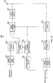
- FIG. 10 is a block diagram illustrating a configuration of base station 100 according to the embodiment of the present invention.
- error determining section 101 determines whether or not there is any error in a data signal (uplink data) received from error correction decoding section 111 which will be described later. The determination result is outputted to control information generation section 102.
- control information generation section 102 determines a resource to which the data signal is assigned and generates DL assignment which is assignment information.
- control information generation section 102 determines a resource to which the data signal is assigned and generates UL grant which is assignment information. Note that control information generation section 102 determines whether or not to retransmit the signal (that is, uplink data) to the terminal based on the determination result received from error determining section 101.
- the generated assignment information is outputted to signal assignment section 106 as information to be transmitted by PDCCH (or EPDCCH).
- the DL assignment is also outputted to signal assignment section 106 as control information for transmitting downlink data.
- the UL grant is outputted to radio receiving section109 to receive uplink data.
- control information generation section 102 Based on the determination result received from error determining section 101, if a signal need not be retransmitted by the terminal or a signal is adaptively retransmitted, control information generation section 102 instructs PHICH generation section 103 to generate an ACK. On the other hand, if a signal is non-adaptively retransmitted by the terminal, control information generation section 102 instructs PHICH generation section 103 to generate a NACK.
- PHICH generation section 103 generates an ACK/NACK signal (ACK or NACK, that is, a response signal in response to uplink data transmitted from the TDD eIMTA terminal or non-TDD eIMTA terminal) according to an instruction from control information generation section 102.
- ACK or NACK that is, a response signal in response to uplink data transmitted from the TDD eIMTA terminal or non-TDD eIMTA terminal
- One of a plurality of UL-DL configurations e.g., Config#0 to #6 is set in the terminal that has transmitted uplink data corresponding to the ACK/NACK signal.
- PHICH generation section 103 outputs the generated ACK/NACK signal to signal assignment section 106.
- Error correction coding section 104 performs error correction coding on a transmission data signal (that is, a downlink data signal) and outputs the coded signal to modulation section 105.
- Modulation section 105 modulates the signal received from error correction coding section 104 and outputs the modulated signal to signal assignment section 106.
- Signal assignment section 106 allocates the modulated signal received from modulation section 105 to a resource based on the DL assignment received from control information generation section 102. In addition, signal assignment section 106 assigns DCI including the DL assignment and the UL grant received from control information generation section 102 to a resource region of PDCCH (PDCCH region) (or a resource region of EPDCCH (EPDCCH region)). Furthermore, when an ACK/NACK signal is outputted from PHICH generation section 103, signal assignment section 106 assigns the ACK/NACK signal to the resource region of PHICH. Signal assignment section 106 assigns a response signal to a PHICH resource based on an association between an uplink communication subframe in which uplink data is transmitted and the PHICH resource (I PHICH ) (which will be described later).
- a transmission data signal, control information (assignment information (DL assignment, UL grant) or the like) and PHICH signal (ACK/NACK signal) are assigned to predetermined resources and a transmission signal is thereby generated.
- the generated transmission signal is outputted to radio transmitting section 107.
- Radio transmitting section 107 applies predetermined radio transmission processing such as up-conversion to the transmission signal received from signal assignment section 106 and transmits the transmission signal via antenna 108.
- Radio receiving section 109 receives a signal transmitted from the terminal via antenna 108 and applies predetermined radio reception processing such as down-conversion thereto. Radio receiving section 109 then demultiplexes the signal transmitted from the terminal using the UL grant received from control information generation section 102 and outputs the signal to demodulation section 110.
- Demodulation section 110 applies demodulation processing to the signal received from radio receiving section 109 and outputs the demodulated signal obtained to error correction decoding section 111.
- Error correction decoding section 111 decodes the demodulated signal received from demodulation section 110 and obtains a received data signal. The received data signal obtained is also outputted to error determining section 101.
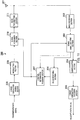
- FIG. 11 is a block diagram illustrating a configuration of terminal 200 according to the present embodiment.
- radio receiving section 202 receives a signal transmitted from base station 100 via antenna 201 and applies predetermined radio reception processing such as down-conversion and outputs the signal subjected to the radio reception processing to signal demultiplexing section 203.
- Signal demultiplexing section 203 extracts a PHICH region signal (ACK/NACK signal) and a PDCCH region signal (control information) from the signal received from radio receiving section 202 and outputs the extracted PHICH region signal and PDCCH region signal to PHICH receiving section 206 and control information receiving section 207 respectively.
- Signal demultiplexing section 203 demultiplexes the response signal from the received signal based on an association between an uplink communication subframe in which uplink data is transmitted and the PHICH resource (I PHICH ) (which will be described later).
- Signal demultiplexing section 203 extracts a signal assigned to a data resource indicated by the DL assignment received from control information receiving section 207 which will be described later (that is, downlink data signal) from the received signal and outputs the extracted signal to demodulation section 204.
- Demodulation section 204 demodulates the signal received from signal demultiplexing section 203 and outputs the demodulated signal to error correction decoding section 205.
- Error correction decoding section 205 decodes the demodulated signal received from demodulation section 204 and outputs the received data signal obtained.
- PHICH receiving section 206 determines whether the PHICH region signal extracted by signal demultiplexing section 203 is ACK or NACK. The determination result is outputted to control information receiving section 207.
- Control information receiving section 207 performs blind decoding on the PDCCH region signal extracted by signal demultiplexing section 203 and thereby extracts control information (e.g., DL assignment or UL grant) intended for terminal 200.
- Control information receiving section 207 outputs the extracted DL assignment to signal demultiplexing section 203 and outputs the UL grant to signal assignment section 210.
- Control information receiving section 207 also functions as a retransmission control section and when the determination result received from PHICH receiving section 206 is a NACK and no UL grant is detected, control information receiving section 207 outputs a signal indicating non-adaptive retransmission (retransmission indication signal) to signal assignment section 210. On the other hand, when the determination result received from PHICH receiving section 206 is an ACK and no UL grant is detected, control information receiving section 207 does not output any signal indicating the assignment to signal assignment section 210.
- Error correction coding section 208 performs error correction coding on a transmission data signal (that is, uplink data) and outputs the coded signal to modulation section 209.
- Modulation section 209 modulates the signal outputted from error correction coding section 208 and outputs the modulated signal to signal assignment section 210.
- signal assignment section 210 Upon receiving UL grant from control information receiving section 207, signal assignment section 210 compares an NDI of the UL grant (NDI of the UL grant this time) with the NDI of the last UL grant in the same retransmission process, determines, when there is any change in the NDI, that new data has been assigned and assigns a modulated signal of the new data outputted from modulation section 209 to data resources according to the UL grant. On the other hand, when there is no change in the NDI, signal assignment section 210 determines that retransmission data has been assigned and assigns the modulated signal of the retransmission data outputted from modulation section 209 to data resources according to the UL grant.
- signal assignment section 210 Upon receiving a retransmission indication signal from control information receiving section 207, signal assignment section 210 allocates the modulated signal of the retransmission data outputted from modulation section 209 to data resources according to the last UL grant in the same retransmission process.
- the assigned signal is outputted to radio transmitting section 211 as a transmission signal.
- Radio transmitting section 211 applies predetermined radio transmission processing such as up-conversion to the transmission signal received from signal assignment section 210 and transmits the transmission signal via antenna 201.
- TDD eIMTA terminal terminal 200
- non-TDD eIMTA terminal including the legacy terminal
- the TDD eIMTA terminal (terminal 200) is first connected to a cell that supports TDD eIMTA using UL-DL configuration which is SIB1-indicated as UL-DL configuration for connection to a cell.
- the TDD eIMTA terminal may be changed to a different UL-DL configuration based on an instruction of base station 100 in the cell after the cell connection. That is, the TDD eIMTA terminal can know not only a UL-DL configuration set in the TDD eIMTA but also an SIB1-indicated UL-DL configuration used by the non-TDD eIMTA terminal.
- Subframe #0 corresponds to the subframe in which a conflict between PHICH resources may occur between the legacy terminal and the TDD eIMTA terminal (terminal 200) in FIGS. 6A and 6B and FIGS. 7A and 7B as described above. More specifically, as shown in FIGS. 6A and 6B and FIGS.
- base station 100 and terminal 200 change the association (0 or 1) of I PHICH with PHICH intended for the legacy terminal for PHICH intended for the TDD eIMTA terminal. That is, in the subframe, base station 100 and terminal 200 use a value obtained by inverting the value of I PHICH (e.g., FIG. 3B ) corresponding to the legacy terminal as I PHICH corresponding to the TDD eIMTA terminal.
- the present embodiment uses different PHICH resources between the legacy terminal and the TDD eIMTA terminal, applies non-adaptive retransmission to corresponding PHICHs and thereby eliminate the aforementioned conflict between PHICH resources.
- PUSCH uplink data
- PUSCH uplink data
- FIG. 12B illustrates PHICH reception timing (PUSCH-PHICH timing) corresponding to uplink data (PUSCH) for terminal 200 and an I PHICH value at each timing in case 1. That is, FIG. 12B shows a state after the above I PHICH value is changed.
- Base station 100 and terminal 200 may assign or demultiplex ACK/NACK signals based on the association between subframes shown in FIG. 12B in which uplink data is transmitted and PHICH resources (I PHICH ) to which ACK/NACK signals are assigned.
- FIG 12B is compared with FIG. 3B .
- a parameter set (I PRB_RA , n DMRS ) to determine a PHICH resource for uplink data (PUSCH) in subframe #4 in terminal 200 may be identical to a parameter set (I PRB_RA , n DMRS ) to determine PHICH resources for uplink data (PUSCH) in subframe #3 in the legacy terminal (Config#0).
- I PHICHs that is, different resource regions are associated with ACK/NACK signals in which, the determination parameter sets (I PRB_RA , n DMRS ) can be identical in subframe #0 between the legacy terminal and the TDD eIMTA terminal. More specifically, as shown in FIG. 12A and FIG. 12B , by changing the value of I PHICH for terminal 200, different I PHICHs , that is, different resource regions are associated with ACK/NACK signals in which, the determination parameter sets (I PRB_RA , n DMRS ) can be identical in subframe #0 between the legacy terminal and the TDD eIMTA terminal. More specifically, as shown in FIG.
- I PHICH has different values between the legacy terminal and terminal 200, and it is thereby possible to completely separate both PHICH resources.
- a leading PRB (I PRB_RA ) of PRBs occupied by terminal 200 never matches a leading PRB (I PRB _ RA ') of PRBs occupied by the legacy terminal.
- the PHICH resource determination parameter set (I PRB_RA , n DMRS ) for uplink data (PUSCH) in subframe #4 in terminal 200 does not match the PHICH resource determination parameter set (I PRB_RA ', n DMRS ') for uplink data (PUSCH) in subframe #4 in the legacy terminal.
- I PHICH for terminal 200
- base station 100 changes the association of I PHICH of the PHICH resources intended for terminal 200 compared to the association of I PHICH used by the legacy terminal (e.g., FIG. 3B ). That is, as shown in FIG.
- Terminal 200 performs retransmission control of uplink data based on the PHICH detection result (e.g., FIG 2 ).
- FIG. 13B illustrates PHICH reception timing (PUSCH-PHICH timing) corresponding to uplink data (PUSCH) for terminal 200 in case 2 and an I PHICH value at each timing. That is, FIG. 13B illustrates a state after the I PHICH value is changed.
- Base station 100 and terminal 200 may assign or separate ACK/NACK signals based on the association shown in FIG. 13B between subframes in which uplink data is transmitted and PHICH resources (I PHICH ) to which the ACK/NACK signals are assigned.
- FIG. 13B is compared with FIG. 3B .
- I PHICHs that is, different resource regions are associated with ACK/NACK signals in which PHICH resource determination parameter sets (I PRB_RA , n DMRS ) are identical between the legacy terminal and the TDD eIMTA terminal in subframe #0 as with case 1. More specifically, as shown in FIG. 13A and FIG. 13B , by changing the I PHICH value for terminal 200, different I PHICHs , that is, different resource regions are associated with ACK/NACK signals in which PHICH resource determination parameter sets (I PRB_RA , n DMRS ) are identical between the legacy terminal and the TDD eIMTA terminal in subframe #0 as with case 1. More specifically, as shown in FIG.
- the value of I PHICH differs between the PHICH resource corresponding to uplink data (PUSCH) in subframe #4 in terminal 200 and the PHICH resource corresponding to uplink data (PUSCH) in subframe #4 in the legacy terminal, and it is thereby possible to completely separate both PHICH resources.
- operation is performed such that different PRBs are assigned to uplink data (PUSCH) of terminal 200 and the legacy terminal in the same subframe.
- the PHICH resource determination parameter set (I PRB_RA , n DMRS ) corresponding to uplink data (PUSCH) in subframe #4 in terminal 200 does not match the PHICH resource determination parameter set (I PRB_RA ', n DMRS ') corresponding to uplink data (PUSCH) in subframe #4 in the legacy terminal.
- the parameter set I PRB_RA ' and n DMRS '
- I PRB _ RA ' is an index indicating the leading PRB assigned to uplink data (PUSCH). For this reason, there is a high possibility that I PRB _ RA '+1 which is an index (index obtained by adding 1) of PRB adjacent to the PRB corresponding to I PRB _ RA ' may also be occupied by the uplink data.
- the possibility that base station 100 may have assigned uplink data whose leading PRB is PRB corresponding to I PRB _ RA '+1 to terminals other than terminal 200 is low. Therefore, even when base station 100 uses PHICH resources associated with I PRB _ RA '+1 in addition to PHICH resources associated with I PRB _ RA '+1 for terminal 200, it is possible to reduce the possibility that constraints may be produced on scheduling for other terminals.
- the other method of implementing case 2 as with case 2, it is possible to completely avoid a conflict between PHICH resources by changing the value of I PHICH . Moreover, the other method of implementing case 2 also has the effect of not increasing the overhead of PHICH compared to a case where operation is performed using only the legacy terminal.
- LSI LSI devices
- IC system LSI
- super LSI ultra LSI
- circuit integration is not limited to LSI and may be achieved by dedicated circuitry or a general-purpose processor other than an LSI.
- a field programmable gate array FPGA
- reconfigurable processor which allows reconfiguration of connections and settings of circuit cells in LSI may be used.
- the terminal apparatus is a terminal apparatus capable of changing setting of a configuration pattern of subframes which make up a single frame to one of a plurality of configuration patterns including a subframe in which uplink data is transmitted and a subframe in which a response signal in response to the uplink data is transmitted, the terminal apparatus including: a receiving section that receives a signal transmitted from a base station apparatus; and a demultiplexing section that demultiplexes the response signal from the signal based on an association between the subframe in which the uplink data is transmitted and a resource to which the response signal is assigned, in which, when a response signal transmitted in a first subframe of a first configuration pattern set in the terminal apparatus corresponds to uplink data transmitted in a second subframe and a response signal transmitted in the first subframe of a second configuration pattern set in another terminal apparatus that is not capable of changing the setting of the configuration pattern corresponds to uplink data transmitted in a third subframe different from the second subframe, in the first subframe, a
- the first resource is included in a region different from a region including the second resource.
- the first resource is a resource associated with a physical resource block having an index obtained by adding one to an index of a physical resource block used for the uplink data transmitted in the third subframe.
- a base station apparatus includes: a generation section that generates a response signal in response to uplink data transmitted from a terminal apparatus capable of changing setting of a configuration pattern of subframes making up a single frame to one of a plurality of configuration patterns including a subframe in which uplink data is transmitted and a subframe in which a response signal in response to the uplink data is transmitted; an assignment section that assigns the response signal to a resource based on an association between a subframe in which the uplink data is transmitted and the resource to which the response signal is assigned; and a transmitting section that transmits a signal including the response signal, in which, when a response signal transmitted in a first subframe of a first configuration pattern set in the terminal apparatus corresponds to uplink data transmitted in a second subframe and a response signal transmitted in the first subframe of a second configuration pattern set in another terminal apparatus that is not capable of changing the setting of the configuration pattern corresponds to uplink data transmitted in a third subframe different from the second subframe, in the first subframe, a
- a reception method is a reception method for terminal apparatus capable of changing setting of a configuration pattern of subframes making up a single frame to one of a plurality of configuration patterns including a subframe in which uplink data is transmitted and a subframe in which a response signal in response to the uplink data is transmitted, the method including: receiving a signal transmitted from a base station apparatus; and demultiplexing the response signal from the signal based on an association between the subframe in which the uplink data is transmitted and a resource to which the response signal is assigned, in which, when a response signal transmitted in a first subframe of a first configuration pattern set in the terminal apparatus corresponds to uplink data transmitted in a second subframe and a response signal transmitted in the first subframe of a second configuration pattern set in another terminal apparatus that is not capable of changing the setting of the configuration pattern corresponds to uplink data transmitted in a third subframe different from the second subframe, in the first subframe, a first resource assigned to the response signal in response to the uplink data transmitted from the terminal apparatus in
- a transmission method includes: generating a response signal in response to uplink data transmitted from a terminal apparatus capable of changing setting of a configuration pattern of subframes making up a single frame to one of a plurality of configuration patterns including a subframe in which uplink data is transmitted and a subframe in which a response signal in response to the uplink data is transmitted; assigning the response signal to a resource based on an association between a subframe in which the uplink data is transmitted and the resource to which the response signal is assigned; and transmitting a signal including the response signal, in which, when a response signal transmitted in a first subframe of a first configuration pattern set in the terminal apparatus corresponds to uplink data transmitted in a second subframe and a response signal transmitted in the first subframe of a second configuration pattern set in another terminal apparatus that is not capable of changing the setting of the configuration pattern corresponds to uplink data transmitted in a third subframe different from the second subframe, in the first subframe, a first resource assigned to the response signal in response to the uplink data transmitted from
- the present invention is useful in mobile communication systems, for example.
Landscapes
- Engineering & Computer Science (AREA)
- Signal Processing (AREA)
- Computer Networks & Wireless Communication (AREA)
- Quality & Reliability (AREA)
- Mobile Radio Communication Systems (AREA)
Description
- The present invention relates to a terminal apparatus, a base station apparatus, a reception method and a transmission method.
- 3GPP LTE adopts OFDMA (Orthogonal Frequency Division Multiple Access) as a downlink communication scheme. In a radio communication system to which 3GPP LTE is applied, a base station (which may also be called "eNB") transmits a synchronization signal (Synchronization Channel: SCH) and broadcast signal (Broadcast Channel: BCH) using predetermined communication resources. A terminal (which may also be called "UE") captures SCH and thereby secures synchronization with the base station. The terminal then reads BCH information and thereby acquires a parameter specific to the base station (e.g., frequency bandwidth) (see
NPLs - After completion of the acquisition of the parameter specific to the base station, the terminal sends a connection request to the base station and thereby establishes communication with the base station. The base station transmits control information to the terminal with which communication has been established via a downlink control channel such as PDCCH (Physical Downlink Control Channel) as appropriate.
- The terminal then performs "blind detection" of a plurality of pieces of control information (which may also be called "downlink control information (DCI)") included in the received PDCCH signal. That is, the control information includes a CRC (Cyclic Redundancy Check) portion and this CRC portion is masked with a terminal ID of the transmission target terminal by the base station. Therefore, the terminal cannot determine whether or not the received control information is control information intended for the terminal until the terminal demasks the CRC portion with the terminal ID of the terminal itself. When the demasking result shows that CRC calculation is OK, it is determined in this blind detection that the control information is intended for the terminal itself. The downlink control information includes DL (downlink) assignment indicating assignment information of downlink data and UL (uplink) grant indicating assignment information of uplink data, for example.
- Next, an uplink retransmission control method in 3GPP LTE will be described. In LTE, UL grant which is assignment information of uplink data is transmitted to the terminal by PDCCH. Here, in an FDD (Frequency Division Duplex) system, a UL grant indicates resource assignment within a target subframe which is the fourth subframe from the subframe in which the UL grant is transmitted.
- Meanwhile, in a TDD (Time Division Duplex) system, a UL grant indicates resource assignment within a target subframe which is the fourth or after the fourth subframe from the subframe in which the UL grant is transmitted. This will be described more specifically using
FIG. 1 . In the TDD system, a downlink component carrier (which may also be called "downlink CC (Component Carrier)") and an uplink component carrier (which may also be called "uplink CC") are in the same frequency band, and the TDD system realizes downlink communication and uplink communication by switching between downlink and uplink in a time-division manner. For this reason, in the TDD system, a downlink component carrier can also be expressed as "downlink communication timing in a component carrier." An uplink component carrier can also be expressed as "uplink communication timing in a component carrier." Switching between the downlink component carrier and the uplink component carrier is performed based on a UL-DL configuration as shown inFIG. 1 . The UL-DL configuration is indicated to the terminal by a broadcast signal called "SIB1 (System Information Block Type 1)" (SIB1 indication), the value thereof is the same throughout the entire system and the value is not expected to be changed frequently. In the UL-DL configuration shown inFIG. 1 , timings in units of subframes (that is, units of 1 msec) are configured for downlink communication (DL: Downlink) and uplink communication (UL: Uplink) per frame (10 msec). The UL-DL configuration allows for building a communication system that can flexibly respond to demand for more throughput for either downlink communication or uplink communication by changing a subframe ratio between downlink communication and uplink communication. For example,FIG. 1 illustrates UL-DL configurations (Config# 0 to 6) with different subframe ratios between downlink communication and uplink communication. InFIG. 1 , a downlink communication subframe is represented by "D," an uplink communication subframe is represented by "U" and a special subframe is represented by "S." Here, the special subframe is a subframe when a downlink communication subframe is switched to an uplink communication subframe. In the special subframe, downlink data communication may also be performed as in the case of a downlink communication subframe. As shown by a solid line arrow inFIG 1 (UL grant-PUSCH timing), a subframe to which uplink data for UL grant (PUSCH: Physical Uplink Shared Channel) is assigned is an uplink communication subframe which is the fourth or after the fourth subframe from the subframe in which the UL grant is indicated, and is uniquely defined as shown inFIG. 1 . - Uplink retransmission control (UL retransmission control) supports non-adaptive retransmission in which retransmission data is assigned to the same frequency resource as the one to which uplink data is assigned at the time of the last transmission and adaptive retransmission in which retransmission data can be assigned to a frequency resource different from the one to which uplink data was assigned at the last transmission (e.g., see NPL 4). In non-adaptive retransmission, only PHICH (Physical Hybrid ARQ Indicator CHannel) for transmitting an ACK/NACK signal (response signal), in response to uplink data, to the terminal is used as a channel for a retransmission control signal. When requesting the terminal to perform retransmission, the base station transmits a NACK to the terminal using PHICH and transmits an ACK using PHICH when not requesting the terminal to perform retransmission. In non-adaptive retransmission, since the base station can designate retransmission using only PHICH, non-adaptive retransmission has an advantage that the overhead of a control signal transmitted over downlink necessary to designate retransmission is small.
- Here, in the FDD system, PHICH is indicated to the terminal using a resource within a target subframe which is the fourth subframe from the subframe in which uplink data is transmitted. Meanwhile, in the TDD system, PHICH is indicated to the terminal using a resource within a target subframe which is the fourth or after the fourth subframe from the subframe in which uplink data is transmitted. This will be described more specifically using
FIG 1 . As shown by a broken line arrow (PUSCH-PHICH timing) inFIG. 1 , a subframe to which ACK/NACK (PHICH) in response to uplink data (PUSCH) is assigned is a downlink communication subframe orspecial subframe 4 or more subframes after a subframe in which the uplink data is indicated and is uniquely defined as shown inFIG. 1 . - In adaptive retransmission, the base station transmits an ACK using PHICH while designating retransmission and a retransmission resource using UL grant for indicating resource assignment information. UL grant includes a bit called "NDI (New Data Indicator)" and this bit is binary having 0 or 1. The terminal compares an NDI of the received UL grant this time with an NDI of the last UL grant in the same retransmission process (HARQ (Hybrid ARQ) process), determines that new data has been assigned when there is a change in the NDI or determines that retransmission data has been assigned when there is no change in the NDI. Since adaptive retransmission allows the amount of resources and MCS (Modulation and Coding Scheme) to be changed according to a required SINR (Signal-to-Interference and Noise power Ratio) of retransmission data, adaptive retransmission has an advantage that spectrum efficiency improves.
- Since a CRC (Cyclic Redundancy Check) is added to UL grant, a received signal with UL grant has higher reliability than PHICH. For this reason, when the terminal receives PHICH and UL grant, the terminal follows an instruction of UL grant.
-
FIG. 2 shows an example of a procedure for UL retransmission control in the terminal. InFIG. 2 , in step (hereinafter abbreviated as "ST") 11, the terminal determines whether or not there is UL grant. When there is UL grant (ST11: YES), the flow proceeds to ST12 and when there is no UL grant (ST11: NO), the flow proceeds to ST15. - In ST12, the terminal compares the NDI of UL grant this time with the NDI of the last UL grant in the same retransmission process and determines whether or not there is any change in the NDI. When there is a change in the NDI (ST12: YES), the flow proceeds to ST13 and when there is no change in the NDI (ST12: NO), the flow proceeds to ST14.
- The terminal transmits new data to the base station in ST13 and transmits retransmission data to the base station through adaptive retransmission in ST14.
- In ST15, the terminal determines whether or not PHICH is NACK. When PHICH is NACK (ST15: YES), the flow proceeds to ST16, and when PHICH is ACK (ST15: NO), the flow proceeds to ST17.
- In ST16, the terminal transmits retransmission data to the base station through non-adaptive retransmission, and in ST17, suspending is applied, so that the terminal suspends retransmission control.
- Next, a configuration of PHICH will be described.
- It should be noted that in an LTE system and an LTE-A (LTE-Advanced) system which is an evolved version of LTE, one RB (Resource Block) is made up of 12 subcarriers × 0.5 msec and a unit combining two RBs on the time domain is called "RB pair." Therefore, the RB pair is made up of 12 subcarriers × 1 msec. When the RB pair represents a block of 12 subcarriers on the frequency domain, the RB pair may be simply called "RB." In addition, a unit of 1 subcarrier × 1 OFDM symbol is called "1 RE (Resource Element)." 1 REG (Resource Element Group) is made up of 4 REs.
- First, in coding of PHICH, ACK/NACK (1 bit) is subjected to three-time repetition. The number of PHICHs is one of {1/6, 1/2, 1, 2} times the number of RBs and is indicated by PBCH (Physical Broadcast Channel). The base station can transmit 8 PHICHs in 3 REGs (=12 REs) through code multiplexing and IQ multiplexing with SF (spreading factor) = 4. The 8 PHICHs arranged on 3 REGs are called a PHICH group and expressed as "number of PHICH groups (that is, the number of resources) Ngroup PHICH is 8." In the FDD system, the number of PHICH groups Ngroup PHICH takes the same value in all subframes.
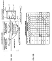
- Meanwhile, in the TDD system, as shown in
FIG 3A , a factor (mi) of number of PHICH groups is defined in each UL-DL configuration and each downlink communication subframe or special subframe. The total number of PHICH groups (=factor mi of number of PHICH groups Ngroup PHICH × the number of PHICH groups) is changed for each subframe using this factor. In the FDD system, the factor of number of PHICH groups is always 1 irrespective of subframes. - The reason that the total number of PHICHs varies from one subframe to another in the TDD system will be described using
FIG. 3B. FIG. 3B illustrates the number of subframes before a PHICH received by the terminal in subframe #n is associated with a PUSCH transmitted by the terminal. Blanks inFIG. 3B indicate that there are no PHICHs. For example, as shown inFIG. 3B , PHICH insubframe # 1 ofConfig# 0 is associated with PUSCH transmitted insubframe # 7 which is 4 subframes earlier (seeFIG. 1 ). Insubframe # 1 ofConfig# 0, since PUSCH in one subframe is associated with PHICH in one subframe, factor mi of the number of PHICH groups is assumed to be 1 as in the case of the FDD system (seeFIG. 3A ). On the other hand, as shown inFIG. 3B , PHICH insubframe # 0 ofConfig# 0 is associated with PUSCHs transmitted insubframe # 3 which is 7 subframes earlier and insubframe # 4 which is 6 subframes earlier respectively. That is, insubframe # 0 ofConfig# 0, the terminal receives PHICHs corresponding to two PUSCHs. Thus, insubframe # 0 ofConfig# 0, twice as many resources for PHICH (hereinafter referred to as "PHICH resources") as those insubframe # 1 ofConfig# 0 are required, and therefore factor mi of number of PHICH groups is considered to be 2 (seeFIG. 3A ). - In
FIG. 3B , two PHICHs intended for the same terminal received in the same subframe (e.g.,subframes # 0 and 5) are distinguished by parameter IPHICH. For example, insubframe # 0 ofConfig# 0, PHICH corresponding toPUSCH 7 subframes earlier corresponds to IPHICH=0 and PHICH corresponding toPUSCH 6 subframes earlier corresponds to IPHICH=1. The same applies tosubframe # 5 ofConfig# 0. For PHICHs in other UL-DL configurations and subframes, IPHICH is always 0. - A PHICH resource is represented by a combination {ngroup PHICH, nseq PHICH} of an index of the total number of PHICH resources ngroup PHICH and an index of orthogonal sequence nseq PHICH. The index of the total number of PHICH resources ngroup PHICH and the index of orthogonal sequence nseq PHICH are expressed by following
equations


- Here, NPHICH SF is a spreading factor (SF) that varies depending on the length of a CP (Cyclic Prefix). IPRB_RA is a minimum value of a PRB (Physical RB) index to which PUSCH corresponding to PHICH is assigned. In
transport block # 1, IPRB_RA is a minimum value of a PRB (Physical RB) index to which PUSCH corresponding to PHICH is assigned. Intransport block # 2, IPRB_RA is a value obtained by adding 1 to the minimum value of the PRB index to which PUSCH corresponding to PHICH is assigned. Meanwhile, nDMRS is a cyclic shift value of DMRS (Demodulation Reference Signal) included in UL grant that indicates PUSCH corresponding to PHICH. Since IPRB_RA and nDMRS depend on assignment of UL grant and PUSCH, a PHICH resource can be said to be implicitly indicated (implicit signalling) based on the assignment of UL grant and PUSCH. The determined PHICH resource is divided for every value of IPHICH. For example, insubframe # 0 ofConfig# 0, PHICH corresponding toPUSCH 7 subframes earlier and PHICH corresponding toPUSCH 6 subframes earlier are designed such that the PHICH resources do not conflict with each other. - The method of determining PHICH resources in
subframe # 0 ofConfig# 0 will be described usingFIG 4 . As shown inFIG. 4A , there are two PHICHs intended for the same terminal insubframe # 0 ofConfig# 0. One PHICH is PHICH corresponding to PUSCH insubframe # 3 seven subframes earlier and IPHICH=0 is defined. IPRB_RA and nDMRS are uniquely defined by the assignment of PUSCH insubframe # 3 and UL grant indicating the PUSCH. As shown inFIG. 4B , PHICH resources corresponding to PUSCH insubframe # 3 are uniquely defined within a region of ngroup PHICH<Ngroup PHICH by the combination of IPRB_RA and nDMRS, and IPHICH=0. - As shown in
FIG. 4A , the other PHICH is PHICH corresponding to PUSCH insubframe # 4 six subframes earlier and IPHICH=1 is defined. IPRB_RA and nDMRS are uniquely defined by the assignment of PUSCH insubframe # 4 and UL grant indicating the PUSCH (hereinafter described as IPRB_RA' and nDMRS' for distinction). As shown inFIG. 4B , PHICH resources corresponding to PUSCH insubframe # 4 are uniquely defined within the region of Ngroup PHICH≤ngroup PHICH<2∗Ngroup PHICH by the combination of IPRB_RA' and nDMRS' and IPHICH=1. Here,coefficient 2 of 2∗Ngroup PHICH which is an upper limit value of ngroup PHICH corresponds to mi=2 inFIG. 3A . - Mapping of PHICH depends on a cell ID. Therefore, it is difficult to control interference of PHICH with other cells and PHICH may interfere with PDCCH and/or CRS (Cell-specific Reference Signal) in other cells. All of 3 REGs making up PHICH may be arranged on OFDM symbol #0 (not shown) or 3 REGs may be arranged one for each of
OFDM symbols # 0, #1 and #2 as shown inFIG. 4 . Information indicating which PHICH arrangement is used is indicated to the terminal using a broadcast signal. - The number of OFDM symbols (1 to 3) occupied by PDCCH is determined based on the value of CFI (Control Format Indicator) indicated by PCFICH (Physical Control Format Indicator Channel) arranged on
OFDM symbol # 0. Moreover, when detecting PDCCH, the terminal performs blind detection on some resources in resource regions except resources occupied by PCFICH, PHICH and reference signals (hereinafter may also be referred to as "PDCCH resources") of resource regions corresponding to the number of OFDM symbols indicated by CFI fromOFDM symbol # 0. - In the LTE-A system, studies are being carried out on changing UL-DL configuration (hereinafter referred to as "TDD eIMTA (enhancement for DL-UL Interference Management and Traffic Adaptation)," which may also be referred to as "dynamic TDD" or "flexible TDD"). Exemplary purposes of TDD eIMTA include provision of a service that meets the needs of users by flexible changes of a UL/DL ratio or reduction in power consumption at a base station by increasing the UL ratio in a time zone when traffic load is low. As a method of changing UL-DL configuration, the following methods are under study in accordance with the purpose of change: (1) method using indication of an SI (System Information) signaling base, (2) method using indication of an RRC (higher layer) signaling base, (3) method using indication of a MAC (Media Access Control layer) signaling base and (4) method using indication of an L1 (Physical Layer) signaling base.
- Method (1) is to change the least frequent UL-DL configuration. Method (1) is suitable for a case where the purpose is to reduce power consumption at a base station by increasing the UL ratio, for example, in a time zone when traffic load is low (e.g., midnight or early morning). Method (4) is to change the most frequent UL-DL configuration change. The number of terminals connected is smaller in a small cell such as a pico cell than in a large cell such as a macro cell. In a pico cell, UL/DL traffic in the entire pico cell is determined depending on the level of UL/DL traffic in a small number of terminals connected to the pico cell. For this reason, UL/DL traffic in the pico cell fluctuates drastically with time. Thus, method (4) is suitable for a case where UL-DL configuration is changed to follow a time fluctuation of UL/DL traffic in a small cell such as a pico cell. Method (2) and method (3) are positioned between method (1) and method (4) and suitable for a case where UL-DL configuration is changed with medium frequency.
-
- NPL1
3GPP TS 36.211 V10.1.0, "Physical Channels and Modulation (Release 10)," March 2011 - NPL2
3GPP TS 36.212 V10.1.0, "Multiplexing and channel coding (Release 10)," March 2011 - NPL3
3GPP TS 36.213 V10.1.0, "Physical layer procedures (Release 10)," March 2011 - NPL4
R1-074811, "Semi-static Configuration of Non-adaptive and Adaptive HARQ in E-UTRA Downlink" - A case will be considered where a terminal using an SIB1-indicated UL-DL configuration (hereinafter may be referred to as "non-TDD eIMTA terminal" or "legacy terminal") coexists with a terminal that supports TDD eIMTA using UL-DL configuration which is different from the SIB1-indicated UL-DL configuration (hereinafter may be referred to as "TDD eIMTA terminal").
- As shown in
FIG. 3B , the LTE system and LTE-A system define PUSCH timing corresponding to PHICH for each UL-DL configuration (timing relating to uplink retransmission control). Moreover, as shown inFIG. 3A , factor (mi) of the number of PHICH groups is defined in association with PHICH reception timing in a terminal. Therefore, the timing relating to uplink retransmission control and a factor of the number of PHICH groups may differ between a legacy terminal using SIB1-indicated UL-DL configuration and a TDD eIMTA terminal using UL-DL configuration which is different from the SIB1- indicated UL-DL configuration. - As an example,
FIG. 6A illustrates a case whereConfig# 0 is set in a legacy terminal andConfig# 6 is set in a TDD eIMTA terminal. That is, inFIG. 6A , insubframe # 0, the legacy terminal receives PHICH corresponding to PUSCH insubframe # 3 seven subframes earlier defined by IPHICH=0 and further receives PHICH corresponding to PUSCH insubframe # 4 six subframes earlier defined by IPHICH=1. On the other hand, insubframe # 0, the TDD eIMTA terminal receives PHICH corresponding to PUSCH insubframe # 4 six subframes earlier defined by IpHICH=0. -
FIG. 6B illustrates resources of PHICH corresponding to the legacy terminal and the TDD eIMTA terminal within a PHICH resource region. Here, a case will be considered where a parameter set (IPRB_RA, nDMRS) for PUSCH assignment insubframe # 3 in the legacy terminal (Config#0) and UL grant indicating the PUSCH is identical to a parameter set (IPRB_RA, nDMRS) for PUSCH assignment insubframe # 4 in the TDD eIMTA terminal (Config#6) and UL grant indicating the PUSCH. This means that PUSCH of the legacy terminal insubframe # 3 and PUSCH of the TDD eIMTA terminal insubframe # 4 have cyclic shift values corresponding to the same leading PRB index and the same DMRS. At this time, IPHICH=0 is defined for PHICH corresponding to each PUSCH. Therefore, as shown inFIG. 6B , PHICH resources for PUSCH transmission insubframe # 3 for the legacy terminal (Config#0) and PHICH resources for PUSCH transmission for the TDD eIMTA terminal (Config#6) insubframe # 4 conflict with each other. - This causes a problem in that PHICH for each PUSCH is not correctly indicated to each terminal unnecessary retransmission is generated or retransmission is not performed when retransmission is necessary, for example. In addition, a problem similar to that in
FIG. 6B also occurs whenConfig# 0 is set in the legacy terminal andConfig# 3 is set in the TDD eIMTA terminal (not shown), for example. - Next,
FIG. 7A illustrates an example of a case whereConfig# 6 is set in the legacy terminal andConfig# 0 is set in the TDD eIMTA terminal. That is, inFIG 7A , insubframe # 0, the legacy terminal receives PHICH corresponding to PUSCH insubframe # 4 six subframes earlier defined by IPHICH=0. On the other hand, the TDD eIMTA terminal receives PHICH corresponding to PUSCH insubframe # 3 seven subframes earlier defined by IPHICH=0 and further receives PHICH corresponding to PUSCH insubframe # 4 six subframes earlier defined by IPHICH=1. -
FIG. 7B illustrates resources of PHICH for the legacy terminal and the TDD eIMTA terminal within the PHICH resource region. Here, a case will be considered where a parameter set (IPRB_RA, nDMRS) corresponding to PUSCH assignment ofsubframe # 4 in the legacy terminal (Config#6) and UL grant indicating the PUSCH is identical to a parameter set (IPRB_RA, nDMRS) corresponding to PUSCH assignment ofsubframe # 3 in the TDD eIMTA terminal (Config#0) and UL grant indicating the PUSCH. This means that PUSCH of the legacy terminal insubframe # 4 and PUSCH of the TDD eIMTA terminal insubframe # 3 have cyclic shift values corresponding to the same leading PRB index and the same DMRS. At this time, IPHICH=0 is defined for PHICH corresponding to each PUSCH. Therefore, as shown inFIG. 7B , PHICH resources for PUSCH transmission insubframe # 4 in the legacy terminal (Config#6) and PHICH resources for PUSCH transmission insubframe # 3 in the TDD eIMTA terminal (Config#0) conflict with each other. - This causes a problem in that PHICH for each PUSCH is not correctly indicated to each terminal and unnecessary retransmission is generated or retransmission is not performed when it is necessary. In addition, a problem similar to those in
FIG. 7B also occurs whenConfig# 3 is set in the legacy terminal andConfig# 0 is set in the TDD eIMTA terminal (not shown), for example. -
WO 2007/091831 discloses a method for transmitting radio resources in a mobile communication system. The method includes receiving a random access channel (RACH) preamble from a plurality of UEs and transmitting response information associated with the received preambles over a common channel wherein the plurality UEs can access the common channel and receive corresponding information. If a HARQ scheme is used when a UE transmits data to the eNode-B using uplink radio resources allocated over the RACH, the eNode-B does not pre-allocate uplink radio resources required for re-transmission and performs allocation of radio resources for a first transmission of HARQ. If the re-transmission is required, the eNode-B allocates the radio resources required for the re-transmission with the NACK signal. If re-transmission is not required, the method can reduce an amount of wasted radio resources. -
EP2 159 939 A1 discloses a base station device which includes: a random access identification information storage that stores random access identification information and mobile station device identification information correlated with the random access identification information, the random access identification information being allocated by the base station device to the mobile station device, and the mobile station device identification information identifying the mobile station device; a random access receiver that receives random access identification information transmitted by the mobile station device performing random access; a scheduler that, if the random access identification information received is stored in the random access identification information storage while being correlated with the mobile station device identification information, determines whether to transmit random access response information that is a response to the random access corresponding to the random access identification information received by using the mobile station device identification information, or by using identification information having not been allocated to a specific mobile station device, the identification information being allocated for transmitting the response to the random access; and a transmitter that allocates and transmits the random access response information based on the determination by the scheduler. -
WO2010/025279 A1 discloses the art of supporting multiple access technologies in a wireless environment, where new and legacy terminals operate at a common terrestrial radio access network, and where PHICH resources are reserved for both the new and the legacy terminals in a way, that avoids conflicts between the reservations. - An object of the present invention is to provide a terminal apparatus, a base station apparatus, a reception method and a transmission method capable of avoiding a conflict between PHICH resources when there is a mixture of terminals in which different UL-DL configurations are set.
- The present invention attains the above object by means defined in the independent claims.
- Preferred embodiments are claimed in the dependent claims.
- According to the present invention, it is possible to avoid a conflict between PHICH resources when there is a mixture of terminals in which different UL-DL configurations are set.
-
-
FIG. 1 is a diagram provided for describing UL-DL configuration and UL retransmission control timing in TDD; -
FIG. 2 is a flowchart illustrating an uplink communication retransmission control procedure; -
FIGS. 3A and 3B are diagrams illustrating factors of number of PHICH groups corresponding to UL-DL configuration and PUSCH-PHICH timing; -
FIGS. 4A and 4B are diagrams illustrating a method of determining PHICH resources corresponding to PUSCH-PHICH timing; -
FIG. 5 is a diagram illustrating an example of PHICH mapping; -
FIGS. 6A and 6B are diagrams provided for describing problems involved in a case where a legacy terminal is UL-DL configuration# 0; -
FIGS. 7A and 7B are diagrams provided for describing problems involved in a case where a legacy terminal is UL-DL configuration# -
FIG. 8 is a block diagram illustrating a main configuration of a base station according to an embodiment of the present invention; -
FIG. 9 is a block diagram illustrating a main configuration of a terminal according to the embodiment of the present invention; -
FIG. 10 is a block diagram illustrating a configuration of the base station according to the embodiment of the present invention; -
FIG. 11 is a block diagram illustrating a configuration of the terminal according to the embodiment of the present invention; -
FIGS. 12A and 12B are diagrams provided for describing a case where a legacy terminal according to the embodiment of the present invention is UL-DL configuration# 0; -
FIGS. 13A and 13B are diagrams provided for describing a case where the legacy terminal according to the embodiment of the present invention is UL-DL configuration# -
FIGS. 14 A and 14B are diagrams provided for describing a case where the legacy terminal according to the embodiment of the present invention is UL-DL configuration# - The invention made is disclosed in the attached set of independent claims.
- Further embodiments are disclosed in the attached set of dependent claims.
- Hereinafter, an embodiment of the present invention will be described in detail with reference to the accompanying drawings. Throughout the embodiment, the same elements are assigned the same reference numerals and any duplicate description of the elements is omitted.
-
FIG. 8 is a main configuration diagram ofbase station 100 according to the present embodiment. Inbase station 100,PHICH generation section 103 generates a response signal (ACK/NACK signal) in response to uplink data transmitted from terminal 200 whose setting can be changed to one of a plurality of configuration patterns (UL-DL configurations) of subframes making up one frame, each configuration pattern including a subframe in which uplink data is transmitted and a subframe in which a response signal (ACK/NACK signal) in response to the uplink data is transmitted.Signal assignment section 106 assigns a response signal to a PHICH resource based on an association between a subframe in which uplink data is transmitted and a resource (PHICH resource (IPHICH)) to which the response signal is assigned.Radio transmitting section 107 transmits a signal including the response signal. -
FIG. 9 is a main configuration diagram ofterminal 200 according to the present embodiment.Terminal 200 is a terminal whose setting can be changed to one of a plurality of configuration patterns (UL-DL configurations) of subframes making up one frame, each configuration pattern including a subframe in which uplink data is transmitted and a subframe in which a response signal (ACK/NACK signal) in response to the uplink data is transmitted.Radio receiving section 202 receives a signal transmitted frombase station 100.Signal demultiplexing section 203 demultiplexes the signal into a response signal based on an association between a subframe in which uplink data is transmitted and a resource (PHICH resource (IPHICH)) to which a response signal is assigned. - In a first configuration pattern set in terminal 200 (TDD eIMTA terminal), when a response signal transmitted in a first subframe corresponds to uplink data transmitted in a second subframe, a response signal transmitted in the first subframe corresponds to uplink data transmitted in a third subframe different from the second subframe in a second configuration pattern set in another terminal (non-TDD eIMTA terminal) whose configuration pattern setting cannot be changed, in the first subframe, a first resource (PHICH resource) assigned to a response signal in response to uplink data transmitted from terminal 200 in the second subframe is different from a second resource (PHICH resource) assigned to a response signal in response to uplink data transmitted from the other terminal in the third subframe.
-
FIG. 10 is a block diagram illustrating a configuration ofbase station 100 according to the embodiment of the present invention. - In
FIG. 10 , using CRC or the like,error determining section 101 determines whether or not there is any error in a data signal (uplink data) received from errorcorrection decoding section 111 which will be described later. The determination result is outputted to controlinformation generation section 102. - When there is a data signal to be transmitted over the downlink, control
information generation section 102 determines a resource to which the data signal is assigned and generates DL assignment which is assignment information. When there is a data signal to be assigned to the uplink, controlinformation generation section 102 determines a resource to which the data signal is assigned and generates UL grant which is assignment information. Note that controlinformation generation section 102 determines whether or not to retransmit the signal (that is, uplink data) to the terminal based on the determination result received fromerror determining section 101. The generated assignment information is outputted to signalassignment section 106 as information to be transmitted by PDCCH (or EPDCCH). The DL assignment is also outputted to signalassignment section 106 as control information for transmitting downlink data. The UL grant is outputted to radio receiving section109 to receive uplink data. - Based on the determination result received from
error determining section 101, if a signal need not be retransmitted by the terminal or a signal is adaptively retransmitted, controlinformation generation section 102 instructsPHICH generation section 103 to generate an ACK. On the other hand, if a signal is non-adaptively retransmitted by the terminal, controlinformation generation section 102 instructsPHICH generation section 103 to generate a NACK. -
PHICH generation section 103 generates an ACK/NACK signal (ACK or NACK, that is, a response signal in response to uplink data transmitted from the TDD eIMTA terminal or non-TDD eIMTA terminal) according to an instruction from controlinformation generation section 102. One of a plurality of UL-DL configurations (e.g.,Config# 0 to #6) is set in the terminal that has transmitted uplink data corresponding to the ACK/NACK signal.PHICH generation section 103 outputs the generated ACK/NACK signal to signalassignment section 106. - Error
correction coding section 104 performs error correction coding on a transmission data signal (that is, a downlink data signal) and outputs the coded signal tomodulation section 105. -
Modulation section 105 modulates the signal received from errorcorrection coding section 104 and outputs the modulated signal to signalassignment section 106. -
Signal assignment section 106 allocates the modulated signal received frommodulation section 105 to a resource based on the DL assignment received from controlinformation generation section 102. In addition,signal assignment section 106 assigns DCI including the DL assignment and the UL grant received from controlinformation generation section 102 to a resource region of PDCCH (PDCCH region) (or a resource region of EPDCCH (EPDCCH region)). Furthermore, when an ACK/NACK signal is outputted fromPHICH generation section 103,signal assignment section 106 assigns the ACK/NACK signal to the resource region of PHICH.Signal assignment section 106 assigns a response signal to a PHICH resource based on an association between an uplink communication subframe in which uplink data is transmitted and the PHICH resource (IPHICH) (which will be described later). - In this way, a transmission data signal, control information (assignment information (DL assignment, UL grant) or the like) and PHICH signal (ACK/NACK signal) are assigned to predetermined resources and a transmission signal is thereby generated. The generated transmission signal is outputted to
radio transmitting section 107. -
Radio transmitting section 107 applies predetermined radio transmission processing such as up-conversion to the transmission signal received fromsignal assignment section 106 and transmits the transmission signal viaantenna 108. -
Radio receiving section 109 receives a signal transmitted from the terminal viaantenna 108 and applies predetermined radio reception processing such as down-conversion thereto.Radio receiving section 109 then demultiplexes the signal transmitted from the terminal using the UL grant received from controlinformation generation section 102 and outputs the signal todemodulation section 110. -
Demodulation section 110 applies demodulation processing to the signal received fromradio receiving section 109 and outputs the demodulated signal obtained to errorcorrection decoding section 111. - Error
correction decoding section 111 decodes the demodulated signal received fromdemodulation section 110 and obtains a received data signal. The received data signal obtained is also outputted toerror determining section 101. -
FIG. 11 is a block diagram illustrating a configuration ofterminal 200 according to the present embodiment. - In
FIG. 11 ,radio receiving section 202 receives a signal transmitted frombase station 100 viaantenna 201 and applies predetermined radio reception processing such as down-conversion and outputs the signal subjected to the radio reception processing to signaldemultiplexing section 203. -
Signal demultiplexing section 203 extracts a PHICH region signal (ACK/NACK signal) and a PDCCH region signal (control information) from the signal received fromradio receiving section 202 and outputs the extracted PHICH region signal and PDCCH region signal toPHICH receiving section 206 and controlinformation receiving section 207 respectively.Signal demultiplexing section 203 demultiplexes the response signal from the received signal based on an association between an uplink communication subframe in which uplink data is transmitted and the PHICH resource (IPHICH) (which will be described later). -
Signal demultiplexing section 203 extracts a signal assigned to a data resource indicated by the DL assignment received from controlinformation receiving section 207 which will be described later (that is, downlink data signal) from the received signal and outputs the extracted signal todemodulation section 204. -
Demodulation section 204 demodulates the signal received fromsignal demultiplexing section 203 and outputs the demodulated signal to errorcorrection decoding section 205. - Error
correction decoding section 205 decodes the demodulated signal received fromdemodulation section 204 and outputs the received data signal obtained. -
PHICH receiving section 206 determines whether the PHICH region signal extracted bysignal demultiplexing section 203 is ACK or NACK. The determination result is outputted to controlinformation receiving section 207. - Control
information receiving section 207 performs blind decoding on the PDCCH region signal extracted bysignal demultiplexing section 203 and thereby extracts control information (e.g., DL assignment or UL grant) intended forterminal 200. Controlinformation receiving section 207 outputs the extracted DL assignment to signaldemultiplexing section 203 and outputs the UL grant to signalassignment section 210. - Control
information receiving section 207 also functions as a retransmission control section and when the determination result received fromPHICH receiving section 206 is a NACK and no UL grant is detected, controlinformation receiving section 207 outputs a signal indicating non-adaptive retransmission (retransmission indication signal) to signalassignment section 210. On the other hand, when the determination result received fromPHICH receiving section 206 is an ACK and no UL grant is detected, controlinformation receiving section 207 does not output any signal indicating the assignment to signalassignment section 210. - Error
correction coding section 208 performs error correction coding on a transmission data signal (that is, uplink data) and outputs the coded signal tomodulation section 209. -
Modulation section 209 modulates the signal outputted from errorcorrection coding section 208 and outputs the modulated signal to signalassignment section 210. - Upon receiving UL grant from control
information receiving section 207,signal assignment section 210 compares an NDI of the UL grant (NDI of the UL grant this time) with the NDI of the last UL grant in the same retransmission process, determines, when there is any change in the NDI, that new data has been assigned and assigns a modulated signal of the new data outputted frommodulation section 209 to data resources according to the UL grant. On the other hand, when there is no change in the NDI,signal assignment section 210 determines that retransmission data has been assigned and assigns the modulated signal of the retransmission data outputted frommodulation section 209 to data resources according to the UL grant. Upon receiving a retransmission indication signal from controlinformation receiving section 207,signal assignment section 210 allocates the modulated signal of the retransmission data outputted frommodulation section 209 to data resources according to the last UL grant in the same retransmission process. The assigned signal is outputted toradio transmitting section 211 as a transmission signal. -
Radio transmitting section 211 applies predetermined radio transmission processing such as up-conversion to the transmission signal received fromsignal assignment section 210 and transmits the transmission signal viaantenna 201. - Operations of
base station 100 and terminal 200 configured as described above will be described in detail. Here, a TDD eIMTA terminal (terminal 200) whose setting can be changed to one of a plurality of UL-DL configurations and a non-TDD eIMTA terminal (including the legacy terminal) whose UL-DL configuration setting cannot be changed coexist in the same cell covered bybase station 100. - The TDD eIMTA terminal (terminal 200) is first connected to a cell that supports TDD eIMTA using UL-DL configuration which is SIB1-indicated as UL-DL configuration for connection to a cell. The TDD eIMTA terminal may be changed to a different UL-DL configuration based on an instruction of
base station 100 in the cell after the cell connection. That is, the TDD eIMTA terminal can know not only a UL-DL configuration set in the TDD eIMTA but also an SIB1-indicated UL-DL configuration used by the non-TDD eIMTA terminal. -
Subframe # 0 corresponds to the subframe in which a conflict between PHICH resources may occur between the legacy terminal and the TDD eIMTA terminal (terminal 200) inFIGS. 6A and 6B andFIGS. 7A and 7B as described above. More specifically, as shown inFIGS. 6A and 6B andFIGS. 7A and 7B , there is a combination (subframe #3 (seven subframes earlier) and subframe #4 (six subframes earlier)) in which an uplink communication subframe associated with subframe #0 (subframe in which an ACK/NACK signal is transmitted) in UL-DL configuration set in the TDD eIMTA terminal is different from an uplink communication subframe associated withsubframe # 0 in UL-DL configuration set in the non-TDD eIMTA terminal (seeFIG. 3B ). Resource regions corresponding to IPHICH=0 are associated with ACK/NACK signals in response to uplink data transmitted in these different uplink communication subframes respectively (seeFIG. 3B ). For this reason, inFIGS, 6A and7A , insubframe # 0, a conflict between PHICH resources may occur between the legacy terminal and the TDD eIMTA terminal. - In other words, when an ACK/NACK signal transmitted in the first subframe (
subframe # 0 inFIGS. 6A and7A ) in the UL-DL configuration set in the TDD eIMTA terminal corresponds to uplink data transmitted in the second subframe (subframe # 4 inFIG. 6A ,subframe # 3 inFIG. 7A ), and an ACK/NACK signal transmitted in the first subframe (subframe # 0 inFIGS. 6A ,7A ) in the UL-DL configuration set in the non-TDD eIMTA terminal corresponds to uplink data transmitted in a third subframe (subframe # 3 inFIG 6A ,subframe # 4 inFIG. 7A ) different from the second subframe, a conflict between PHICH resources may occur between the non-TDD eIMTA terminal and the TDD eIMTA terminal in the first subframe. - Focusing on these points, in subframes in which a conflict between PHICH resources may occur between the legacy terminal and the TDD eIMTA terminal,
base station 100 and terminal 200 change the association (0 or 1) of IPHICH with PHICH intended for the legacy terminal for PHICH intended for the TDD eIMTA terminal. That is, in the subframe,base station 100 and terminal 200 use a value obtained by inverting the value of IPHICH (e.g.,FIG. 3B ) corresponding to the legacy terminal as IPHICH corresponding to the TDD eIMTA terminal. - By so doing, while, of ACK/NACK signals in response to uplink data transmitted in different uplink communication subframes between the legacy terminal and the TDD eIMTA terminal in the subframe, PHICH resources for the ACK/NACK signal intended for the legacy terminal are resources in the resource region of IPHICH=0 as described above,
base station 100 and terminal 200 can use PHICH resources for ACK/NACK signals intended forterminal 200 as resources in the resource region of IPHICH=1. That is, insubframe # 0, different PHICH resources are assigned to ACK/NACK signals in response to uplink data transmitted in different uplink communication subframes between the legacy terminal and the TDD eIMTA terminal. - By this means, the present embodiment uses different PHICH resources between the legacy terminal and the TDD eIMTA terminal, applies non-adaptive retransmission to corresponding PHICHs and thereby eliminate the aforementioned conflict between PHICH resources.
- Next, the operation will be described in detail focusing on the following two cases.
- <
Case 1>: WhenConfig# 0 is set in non-TDD eIMTA terminal andConfig# 3 orConfig# 6 is set in TDD eIMTA terminal - <
Case 2>: WhenConfig# 3 orConfig# 6 is set in non-TDD eIMTA terminal andConfig# 0 is set in TDD eIMTA terminal - For example, as shown in
FIG. 12A , insubframe # 0 in which a conflict between PHICH resources may occur between the legacy terminal (Config#0) and the TDD eIMTA terminal (terminal 200) (Config# 3 or Config#6), base station 100 (e.g., signal assignment section 106) changes the association of IPHICH of PHICH resources intended forterminal 200 compared to the association (e.g.,FIG 3B ) of IPHICH used by the legacy terminal. That is, as shown inFIG 12A , insubframe # 0,base station 100 associates the PHICH resources corresponding to uplink data (PUSCH) ofsubframe # 4 with IPHICH=1 forterminal 200. - Similarly, in
subframe # 0, terminal 200 (e.g., signal demultiplexing section 203) recognizes PHICH resources corresponding to uplink data (PUSCH) insubframe # 4 as IPHICH=1 and detects PHICH.Terminal 200 then performs retransmission control (e.g.,FIG 2 ) of uplink data based on the detection result of PHICH. -
FIG. 12B illustrates PHICH reception timing (PUSCH-PHICH timing) corresponding to uplink data (PUSCH) forterminal 200 and an IPHICH value at each timing incase 1. That is,FIG. 12B shows a state after the above IPHICH value is changed.Base station 100 and terminal 200 may assign or demultiplex ACK/NACK signals based on the association between subframes shown inFIG. 12B in which uplink data is transmitted and PHICH resources (IPHICH) to which ACK/NACK signals are assigned. - In
subframe # 0,FIG 12B is compared withFIG. 3B . InFIG. 3B , IPHICH=0 is associated with a PHICH resource of an ACK/NACK signal transmitted insubframe # 0 to a terminal in whichConfig# 3 orConfig# 6 is set. In contrast, inFIG. 12B , IPHICH=1 (area enclosed by a dotted line) is associated with a PHICH resource of an ACK/NACK signal transmitted insubframe # 0 toterminal 200 in whichConfig# 3 orConfig# 6 is set. In,FIG. 12B , as withFIG. 3B , IPHICH=0 is associated with PHICH resources of ACK/NACK signals transmitted insubframe # 0 to a terminal in whichConfig# 0 is set. - Here, in
subframe # 0 in which PHICH is transmitted, a parameter set (IPRB_RA, nDMRS) to determine a PHICH resource for uplink data (PUSCH) insubframe # 4 in terminal 200 (Config# 3 or Config#6) may be identical to a parameter set (IPRB_RA, nDMRS) to determine PHICH resources for uplink data (PUSCH) insubframe # 3 in the legacy terminal (Config#0). - In contrast, as shown in
FIG. 12A and FIG. 12B , by changing the value of IPHICH forterminal 200, different IPHICHs, that is, different resource regions are associated with ACK/NACK signals in which, the determination parameter sets (IPRB_RA, nDMRS) can be identical insubframe # 0 between the legacy terminal and the TDD eIMTA terminal. More specifically, as shown inFIG. 12B , a PHICH resource (IPHICH=1) of an ACK/NACK signal for PUSCH in subframe #4 (six subframes earlier) associated withsubframe # 0 inConfig# 3 orConfig# 6 set in the TDD eIMTA terminal is different from a PHICH resource (IPHICH=0) of an ACK/NACK signal for PUSCH in subframe #3 (seven subframes earlier) associated withsubframe # 0 inConfig# 0 set in the legacy terminal. That is, insubframe # 0, the PHICH resource of the ACK/NACK signal for PUSCH insubframe # 4 interminal 200 is included in a region (IPHICH=1) different from the region (IPHICH=0) including the PHICH resource of the ACK/NACK signal for PUSCH insubframe # 3 in the legacy terminal. In this way, IPHICH has different values between the legacy terminal and terminal 200, and it is thereby possible to completely separate both PHICH resources. - Note that in the same subframe, operation is performed such that different PRBs are assigned to uplink data (PUSCH) of
terminal 200 and the legacy terminal. Thus, for example, insubframe # 4 shown inFIG 12A , a leading PRB (IPRB_RA) of PRBs occupied byterminal 200 never matches a leading PRB (IPRB_RA') of PRBs occupied by the legacy terminal. Thus, since IPRB_RA never matches IPRB_RA', the PHICH resource determination parameter set (IPRB_RA, nDMRS) for uplink data (PUSCH) insubframe # 4 interminal 200 does not match the PHICH resource determination parameter set (IPRB_RA', nDMRS') for uplink data (PUSCH) insubframe # 4 in the legacy terminal. Thus, as shown inFIG. 12A and FIG. 12B , the values of IPHICH for terminal 200 are changed, and although the same region (IPHICH=0) is associated with PHICH resources of ACK/NACK signals corresponding to uplink data transmitted in the same uplink communication subframe (subframe #4) between the legacy terminal and the TDD eIMTA terminal insubframe # 0, it is possible to completely separate both PHICH resources. - For example, as shown in
FIG. 13A , insubframe # 0 in which a conflict between PHICH resources may occur between the legacy terminal (Config# 3 or Config#6) and the TDD eIMTA terminal (terminal 200) (Config#0), as withcase 1, base station 100 (e.g., signal assignment section 106) changes the association of IPHICH of the PHICH resources intended forterminal 200 compared to the association of IPHICH used by the legacy terminal (e.g.,FIG. 3B ). That is, as shown inFIG. 13A , insubframe # 0,base station 100 associates a PHICH resource corresponding to uplink data (PUSCH) insubframe # 3 with IPHICH=1 forterminal 200 and associates a PHICH resource corresponding to uplink data (PUSCH) insubframe # 4 with IPHICH=4. - Similarly, in
subframe # 0, terminal 200 (e.g., signal demultiplexing section 203) recognizes a resource of PHICH corresponding to uplink data (PUSCH) insubframe # 3 as IPHICH=1, recognizes a resource of PHICH corresponding to uplink data (PUSCH) insubframe # 4 as IPHICH=0 and detects PHICH.Terminal 200 performs retransmission control of uplink data based on the PHICH detection result (e.g.,FIG 2 ). -
FIG. 13B illustrates PHICH reception timing (PUSCH-PHICH timing) corresponding to uplink data (PUSCH) forterminal 200 incase 2 and an IPHICH value at each timing. That is,FIG. 13B illustrates a state after the IPHICH value is changed.Base station 100 and terminal 200 may assign or separate ACK/NACK signals based on the association shown inFIG. 13B between subframes in which uplink data is transmitted and PHICH resources (IPHICH) to which the ACK/NACK signals are assigned. - In
subframe # 0,FIG. 13B is compared withFIG. 3B . InFIG. 3B , IPHICH=0 is associated with a PHICH resource of an ACK/NACK signal corresponding to PUSCH, seven subframes earlier transmitted insubframe # 0 to a terminal in whichConfig# 0 is set and IPHICH=1 is associated with a PHICH resource of an ACK/NACK signal corresponding to PUSCH, six subframes earlier. In contrast, inFIG 13B , IPHICH=1 is associated with a PHICH resource of an ACK/NACK signal corresponding to PUSCH, seven subframes earlier transmitted insubframe # 0 toterminal 200 in whichConfig# 0 is set, and IPHICH=0 is associated with a PHICH resource of an ACK/NACK signal corresponding to PUSCH, six subframes earlier (area enclosed by a dotted line). InFIG. 13B , as withFIG. 3B , IPHICH=0 is associated with the PHICH resource of the ACK/NACK signal transmitted insubframe # 0 to the terminal in whichConfig# 3 orConfig# 6 is set. - As shown in
FIG. 13A and FIG. 13B , by changing the IPHICH value forterminal 200, different IPHICHs, that is, different resource regions are associated with ACK/NACK signals in which PHICH resource determination parameter sets (IPRB_RA, nDMRS) are identical between the legacy terminal and the TDD eIMTA terminal insubframe # 0 as withcase 1. More specifically, as shown inFIG. 13B , the PHICH resource (IPHICH=1) of the ACK/NACK signal corresponding to PUSCH in subframe #3 (seven subframes earlier) associated withsubframe # 0 inConfig# 0 set in the TDD eIMTA terminal is different from the PHICH resource (IPHICH=0) of the ACK/NACK signal corresponding to PUSCH in subframe #4 (six subframes earlier) associated withsubframe # 0 inConfig# 3 orConfig# 6 set in the non-TDD eIMTA terminal. That is, insubframe # 0, the PHICH resource of the ACK/NACK signal corresponding to PUSCH insubframe # 3 interminal 200 is included in a region (IPHICH=1) different from a region (IPHICH=0) including the PHICH resource of the ACK/NACK signal corresponding to PUSCH insubframe # 4 in the legacy terminal. In this way, the value of IPHICH differs between the PHICH resource corresponding to uplink data (PUSCH) insubframe # 4 interminal 200 and the PHICH resource corresponding to uplink data (PUSCH) insubframe # 4 in the legacy terminal, and it is thereby possible to completely separate both PHICH resources. - As with
case 1, operation is performed such that different PRBs are assigned to uplink data (PUSCH) ofterminal 200 and the legacy terminal in the same subframe. Thus, for example, as shown inFIG. 13A , the PHICH resource determination parameter set (IPRB_RA, nDMRS) corresponding to uplink data (PUSCH) insubframe # 4 interminal 200 does not match the PHICH resource determination parameter set (IPRB_RA', nDMRS') corresponding to uplink data (PUSCH) insubframe # 4 in the legacy terminal. In this way, as shown inFIG. 13A and FIG. 13B , by changing the value of IPHICH forterminal 200, although the identical region (IPHICH=0) is associated with PHICH resources of the ACK/NACK signals corresponding to uplink data transmitted in the same uplink communication subframe (subframe #4) between the legacy terminal and the TDD eIMTA terminal insubframe # 0, both PHICH resources can be separated completely. -
Case 1 andcase 2 have been describes so far. - As described above, according to the present embodiment, even when terminals coexist in which different UL-DL configurations are set, it is possible to avoid a conflict between PHICH resources by changing the value of IPHICH in terminal 200 which is a TDD eIMTA terminal in subframes in which a conflict between PHICH resources may occur. Thus, since PHICH for each PUSCH can be indicated to each terminal correctly, it is possible to solve problems that unnecessary retransmission occurs or retransmission is not performed although it is necessary.
- A case has been described in case 2 (
FIG. 12 andFIG. 13 ) where factor mi of number of PHICH groups insubframe # 0 is set to Config#0 (mi=2) and set toConfig# 3 or Config#6 (mi=1) whichever is the larger (mi=2). In contrast, a case will be described here where factor mi of number of PHICH groups insubframe # 0 is set to Config#0 (mi=2) and set toConfig# 3 or Config#6 (mi=1) whichever is the smaller (mi=1). - In other words,
FIG. 14A and FIG. 14B illustrate examples of cases where factor mi=1 of the PHICH group is set in the TDD eIMTA terminal (terminal 200) (Config#0) so that the number of PHICH resources does not become greater than that when only the legacy terminal (Config# 3 or Config#6:mi=1) is operated (so that the overhead of PHICH does not increase). More specifically,FIG. 14A and FIG. 14B illustrate examples in subframe #0 (seeFIG. 3A ) in which factor mi of number of PHICH groups for the legacy terminal (Config# 3 or Config#6) is smaller than factor mi of number of PHICH groups for terminal 200 (Config#0). - In the method shown in
FIG. 14A ,base station 100 does not secure any PHICH resources (PHICH resources for PUSCH transmitted insubframe # 3, seven subframes earlier) corresponding to IPHICH=1 forterminal 200.Terminal 200 does not receive any PHICH corresponding to IPHICH=1 insubframe # 0. That is,base station 100 and terminal 200 do not secure any PHICH resources corresponding to IPHICH=1 insubframe # 0 and always support only adaptive retransmission for PUSCH transmitted insubframe # 3. The same method as that incase 2 applies to PHICH corresponding to IPHICH=0. - In the method shown in
FIG. 14B ,base station 100 and terminal 200 secure resources determined based on the parameter set (IPRB_RA' and nDMRS') that determines a PHICH resource (PHICH resource for PUSCH transmitted insubframe # 4, six subframes earlier) corresponding to IPHICH=0 as a PHICH resource (PHICH resource for PUSCH transmitted insubframe # 3, seven subframes earlier) corresponding to IPHICH=1 forterminal 200. InFIG. 14B , when parameters relating to PHICH resources corresponding to IPHICH=0 are IPRB_RA' and nDMRS',base station 100 and terminal 200 assume parameters relating to PHICH resources corresponding to IPHICH=1 to be IPRB_RA'+1 and nDMRS'. IPRB_RA' here is an index indicating the leading PRB assigned to uplink data (PUSCH). For this reason, there is a high possibility that IPRB_RA'+1 which is an index (index obtained by adding 1) of PRB adjacent to the PRB corresponding to IPRB_RA' may also be occupied by the uplink data. That is, at timing at which PRB corresponding to IPRB_RA' is assigned, the possibility thatbase station 100 may have assigned uplink data whose leading PRB is PRB corresponding to IPRB_RA'+1 to terminals other than terminal 200 is low. Therefore, even whenbase station 100 uses PHICH resources associated with IPRB_RA'+1 in addition to PHICH resources associated with IPRB_RA'+1 forterminal 200, it is possible to reduce the possibility that constraints may be produced on scheduling for other terminals. - Thus, in the other method of implementing
case 2, as withcase 2, it is possible to completely avoid a conflict between PHICH resources by changing the value of IPHICH. Moreover, the other method of implementingcase 2 also has the effect of not increasing the overhead of PHICH compared to a case where operation is performed using only the legacy terminal. - The embodiment of the present invention has been described so far.
-
- (1) In the above embodiment, the TDD eIMTA terminal (terminal 200) can know not only the UL-DL configuration set therein but also the SIB1-indicated UL-DL configuration used by the non-TDD eIMTA terminal. However, the present embodiment is not limited to this, but the TDD eIMTA terminal need not always reference the SIB1-indicated UL-DL configuration used by the non-TDD eIMTA terminal.
That is, whenConfig# 3 orConfig# 6 is set in the TDD eIMTA terminal (terminal 200), base station 100 (e.g., signal assignment section 106) always changes the association of PHICH resources intended forterminal 200 with IPHICH insubframe # 0 irrespective of the UL-DL configuration used by the legacy terminal.
Similarly, whenConfig# 3 orConfig# 6 is set in the TDD eIMTA terminal (terminal 200), insubframe # 0, terminal 200 (e.g., signal demultiplexing section 203) always recognizes PHICH resources corresponding to uplink data (PUSCH) insubframe # 4 as IPHICH=1 and detects PHICH irrespective of the UL-DL configuration used by the legacy terminal.Terminal 200 then performs retransmission control of uplink data (e.g.,FIG. 2 ) based on the PHICH detection result.
WhenConfig# 0 is set in the TDD eIMTA terminal (terminal 200), base station 100 (e.g., signal assignment section 106) always changes the association of PHICH resources intended forterminal 200 with IPHICH insubframe # 0 irrespective of the UL-DL configuration used by the legacy terminal. That is, insubframe # 0,base station 100 associates a PHICH resource corresponding to uplink data (PUSCH) insubframe # 3 with IPHICH=1 forterminal 200 and associates a PHICH resource corresponding to uplink data (PUSCH) insubframe # 4 with IPHICH=0.
Similarly, whenConfig# 0 is set in the TDD eIMTA terminal (terminal 200), insubframe # 0, terminal 200 (e.g., signal demultiplexing section 203) always recognizes a PHICH resource corresponding to uplink data (PUSCH) insubframe # 3 as IPHICH=1 irrespective of the UL-DL configuration used by the legacy terminal, always recognizes a PHICH resource corresponding to uplink data (PUSCH) insubframe # 4 as IPHICH=0 and detects PHICH.Terminal 200 then performs retransmission control of uplink data based on the PHICH detection result (e.g.,FIG. 2 ).
This allowsbase station 100 to determine PHICH resources irrespective of the SIB1-indicated UL-DL configuration used by the non-TDD eIMTA terminal, making it possible to simplify the configuration of base station 100 (e.g., signal assignment section 106). Similarly, sinceterminal 200 can detect PHICH resources irrespective of the SIB1-indicated UL-DL configuration used by the non-TDD eIMTA terminal, making it possible to simplify the configuration of terminal 200 (e.g., signal demultiplexing section 203). - (2) Moreover, in the above embodiment, as the method of indicating. UL-DL configuration for TDD eIMTA set in a TDD eIMTA terminal (terminal 200), one of the following indication methods may be adopted: method of indicating an RRC (higher layer) signaling base, method of indicating a MAC (Media Access Control layer) signaling base and method of indicating a L1 (Physical Layer) signaling base. When UL-DL configuration for TDD eIMTA set in a TDD eIMTA terminal is different from SIB1-indicated UL-DL configuration used in a non-TDD eIMTA terminal (legacy terminal), the method of indicating an SI (System Information) signaling base may be adopted as the method of indicating UL-DL configuration for TDD eIMTA set in the TDD eIMTA terminal.
- (3) "UL-DL configuration for TDD eIMTA set in a TDD eIMTA terminal" has been described in the above embodiment. However, this is based on the premise that "UL-DL configuration for TDD eIMTA set in the TDD eIMTA terminal" and "UL-DL configuration referencing timing relating to uplink control that defines the factor of number of PHICH groups (that is, PHICH reception timing corresponding to uplink data (PUSCH)" are the same.
However, in an LTE-A system, according to TDD inter-band CA (Carrier Aggregation), when different UL-DL configurations are indicated among a plurality of component carriers to which carrier aggregation is applied, UL-DL configuration that indicates a subframe configuration within one frame may be different from UL-DL configuration referencing timing relating to uplink control (hereinafter, may also be referred to as "UL-DL configuration for timing reference").
When TDD inter-band CA is operated in combination with TDD eIMTA, "UL-DL configuration for TDD eIMTA set in the TDD eIMTA terminal" in the above embodiment is different from "UL-DL configuration for timing reference" referenced by the TDD eIMTA terminal. Therefore, in the above embodiment, the "UL-DL configuration for TDD eIMTA set in the TDD eIMTA terminal" may be regarded as "UL-DL configuration at timing relating to uplink control referenced by the TDD eIMTA terminal." - (4) Each of the embodiments has been described with antennas, but the present invention can be applied to antenna ports in the same manner.
The term "antenna port" refers to a logical antenna including one or more physical antennas. In other words, the term "antenna port" does not necessarily refer to a single physical antenna, and may sometimes refer to an array antenna formed of a plurality of antennas and/or the like.
For example, LTE does not specify the number of physical antennas forming an antenna port, but specifies an antenna port as a minimum unit allowing each base station to transmit a different reference signal.
In addition, an antenna port may be specified as a minimum unit for multiplication of precoding vector weighting. - (5) In the foregoing embodiments, the present invention is configured with hardware by way of example, but the present invention can be also implemented by software in conjunction with hardware.
- In addition, the functional blocks used in the descriptions of the embodiments are typically implemented as LSI devices, which are integrated circuits. These functional blocks may be formed as individual chips, or part or all of the functional blocks may be integrated into a single chip. The term "LSI" is used herein, but the terms "IC," "system LSI," "super LSI" or "ultra LSI" may be used as well depending on the level of integration.
- In addition, the circuit integration is not limited to LSI and may be achieved by dedicated circuitry or a general-purpose processor other than an LSI. After fabrication of LSI, a field programmable gate array (FPGA), which is programmable, or a reconfigurable processor, which allows reconfiguration of connections and settings of circuit cells in LSI may be used.
- Should a circuit integration technology replacing LSI appear as a result of advancements in semiconductor technology or other technologies derived from the technology, the functional blocks could be integrated using such a technology. Another possibility is the application of biotechnology and/or the like.
- As has been described above, the terminal apparatus according to the present disclosure is a terminal apparatus capable of changing setting of a configuration pattern of subframes which make up a single frame to one of a plurality of configuration patterns including a subframe in which uplink data is transmitted and a subframe in which a response signal in response to the uplink data is transmitted, the terminal apparatus including: a receiving section that receives a signal transmitted from a base station apparatus; and a demultiplexing section that demultiplexes the response signal from the signal based on an association between the subframe in which the uplink data is transmitted and a resource to which the response signal is assigned, in which, when a response signal transmitted in a first subframe of a first configuration pattern set in the terminal apparatus corresponds to uplink data transmitted in a second subframe and a response signal transmitted in the first subframe of a second configuration pattern set in another terminal apparatus that is not capable of changing the setting of the configuration pattern corresponds to uplink data transmitted in a third subframe different from the second subframe, in the first subframe, a first resource assigned to the response signal in response to the uplink data transmitted from the terminal apparatus in the second subframe is different from a second resource assigned to the response signal in response to the uplink data transmitted from the other terminal apparatus in the third subframe.
- In the terminal apparatus according to this disclosure, the first resource is included in a region different from a region including the second resource.
- In the terminal apparatus according to this disclosure, when the response signal intended for the terminal apparatus transmitted in the first subframe is a response signal in response to the uplink data transmitted in the second subframe and the uplink data transmitted in the third subframe, the first resource is a resource associated with a physical resource block having an index obtained by adding one to an index of a physical resource block used for the uplink data transmitted in the third subframe.
- A base station apparatus according to this disclosure includes: a generation section that generates a response signal in response to uplink data transmitted from a terminal apparatus capable of changing setting of a configuration pattern of subframes making up a single frame to one of a plurality of configuration patterns including a subframe in which uplink data is transmitted and a subframe in which a response signal in response to the uplink data is transmitted; an assignment section that assigns the response signal to a resource based on an association between a subframe in which the uplink data is transmitted and the resource to which the response signal is assigned; and a transmitting section that transmits a signal including the response signal, in which, when a response signal transmitted in a first subframe of a first configuration pattern set in the terminal apparatus corresponds to uplink data transmitted in a second subframe and a response signal transmitted in the first subframe of a second configuration pattern set in another terminal apparatus that is not capable of changing the setting of the configuration pattern corresponds to uplink data transmitted in a third subframe different from the second subframe, in the first subframe, a first resource assigned to the response signal in response to the uplink data transmitted from the terminal apparatus in the second subframe is different from a second resource assigned to the response signal in response to the uplink data transmitted from the other terminal apparatus in the third subframe.
- A reception method according to the present disclosure is a reception method for terminal apparatus capable of changing setting of a configuration pattern of subframes making up a single frame to one of a plurality of configuration patterns including a subframe in which uplink data is transmitted and a subframe in which a response signal in response to the uplink data is transmitted, the method including: receiving a signal transmitted from a base station apparatus; and demultiplexing the response signal from the signal based on an association between the subframe in which the uplink data is transmitted and a resource to which the response signal is assigned, in which, when a response signal transmitted in a first subframe of a first configuration pattern set in the terminal apparatus corresponds to uplink data transmitted in a second subframe and a response signal transmitted in the first subframe of a second configuration pattern set in another terminal apparatus that is not capable of changing the setting of the configuration pattern corresponds to uplink data transmitted in a third subframe different from the second subframe, in the first subframe, a first resource assigned to the response signal in response to the uplink data transmitted from the terminal apparatus in the second subframe is different from a second resource assigned to the response signal in response to the uplink data transmitted from the other terminal apparatus in the third subframe.
- A transmission method according to this disclosure includes: generating a response signal in response to uplink data transmitted from a terminal apparatus capable of changing setting of a configuration pattern of subframes making up a single frame to one of a plurality of configuration patterns including a subframe in which uplink data is transmitted and a subframe in which a response signal in response to the uplink data is transmitted; assigning the response signal to a resource based on an association between a subframe in which the uplink data is transmitted and the resource to which the response signal is assigned; and transmitting a signal including the response signal, in which, when a response signal transmitted in a first subframe of a first configuration pattern set in the terminal apparatus corresponds to uplink data transmitted in a second subframe and a response signal transmitted in the first subframe of a second configuration pattern set in another terminal apparatus that is not capable of changing the setting of the configuration pattern corresponds to uplink data transmitted in a third subframe different from the second subframe, in the first subframe, a first resource assigned to the response signal in response to the uplink data transmitted from the terminal apparatus in the second subframe is different from a second resource assigned to the response signal in response to the uplink data transmitted from the other terminal apparatus in the third subframe.
- The present invention is useful in mobile communication systems, for example.
-
- 100
- Base station
- 200
- Terminal
- 101
- Error determining section
- 102
- Control information generation section
- 103
- PHICH generation section
- 104, 208
- Error correction coding section
- 105, 209
- Modulation section
- 106, 210
- Signal assignment section
- 107, 211
- Radio transmitting section
- 108, 201
- Antenna
- 109, 202
- Radio receiving section
- 110, 204
- Demodulation section
- 111, 205
- Error correction decoding section
- 203
- Signal demultiplexing section
- 206
- PHICH receiving section
- 207
- Control information receiving section
Claims (8)
- A terminal apparatus (200) supporting Time Division Duplex enhancement for UL-DL Interference Management and Traffic Adaptation, TDD eIMTA, the terminal apparatus (200) being set with a physical hybrid ARQ indicator channel, PHICH, resource for avoiding a conflict between its PHICH resource and a PHICH resource of a legacy terminal apparatus, the terminal apparatus (200) being a terminal apparatus to which a first UL-DL configuration has been indicated by a System Information Block Type 1, SIB1, and to which a second UL-DL configuration has been dynamically indicated, the first UL-DL configuration being to be used by the legacy terminal apparatus and the second UL-DL configuration being different from the first UL-DL configuration, the terminal apparatus comprising:a radio transmitting section (211) adapted to transmit uplink data in a first UL subframe, in a frame according to the second UL-DL configuration,a radio receiving section (202) adapted to receive, in a DL subframe, a signal including a response signal for the uplink data transmitted in the first UL subframe, wherein the DL subframe is a subframe positioned after the first UL subframe and defined in the second UL-DL configuration; anda signal demultiplexing section (203) that is adapted to demultiplex, from the received signal in the DL subframe, the response signal in a first PHICH resource,
whereinthe first PHICH resource is different from a second PHICH resource secured in a same DL subframe in the first UL-DL configuration, the second PHICH resource being for a response signal for uplink data transmitted from the legacy terminal apparatus in a second UL subframe, wherein the first and second UL subframes are timed differently in the second UL-DL configuration and the first UL-DL configuration, respectively. - The terminal apparatus according to claim 1, wherein the first PHICH resource is also different from a third PHICH resource secured in the same DL subframe in the first UL-DL configuration, the third resource being secured for a response signal for uplink data in a UL subframe timed same as the first UL subframe.
- The terminal apparatus according to claim 1, wherein a third PHICH resource, secured in the same DL subframe in the second UL-DL configuration, is also different from the second PHICH resource, wherein the third PHICH resource is secured for a response signal for uplink data in a UL subframe timed same as the second UL subframe.
- The terminal apparatus according to any of claims 1 to 3, wherein the first PHICH resource is included in a region of the DL subframe different from a region including the second PHICH resource.
- The terminal apparatus according to claim 3, wherein, the first PHICH resource occupies a physical resource block having an index in said DL subframe obtained by adding one to an index of a physical resource block occupied by the third PHICH resource.
- A base station apparatus (100) supporting Time Division Duplex enhancement for UL-DL Interference Management and Traffic Adaptation, TDD eIMTA, the base station apparatus (100) setting to a TDD eIMTA terminal a physical hybrid ARQ indicator channel, PHICH, resource for avoiding a conflict between a PHICH resource of the TDD eIMTA terminal apparatus and a PHICH resource of a legacy terminal apparatus, wherein the TDD eIMTA terminal apparatus being a terminal apparatus to which a first UL-DL configuration has been indicated by a System Information Block Type 1, SIB1, and to which a second UL-DL configuration has been dynamically indicated, the first UL-DL configuration being to be used by the legacy terminal apparatus and the second UL-DL configuration being different from the first UL-DL configuration, the base station apparatus (100) comprising:a generation section (103) adapted to generate a response signal for uplink data transmitted in a first UL subframe from the TDD eIMTA terminal apparatus;an assignment section (106) adapted to assign the response signal to a first PHICH resource in a DL subframe, wherein the DL subframe is a subframe positioned after the first UL subframe and defined in the second UL-DL configuration; anda transmitting section (107) adapted to transmit a signal including the response signal in the DL subframe,
whereinthe first PHICH resource is different from a second PHICH resource secured in a same DL subframe in the first UL-DL configuration, the second PHICH resource being for a response signal for uplink data transmitted from the legacy terminal apparatus in a second UL subframe, wherein the first and second UL subframes are timed differently in the second UL-DL configuration and the first UL-DL configuration, respectively. - A reception method for a terminal apparatus (200) supporting Time Division Duplex enhancement for UL-DL Interference Management and Traffic Adaptation, TDD eIMTA, the terminal apparatus (200) being set with a physical hybrid ARQ indicator channel, PHICH, resource for avoiding a conflict between a PHICH resource of the terminal apparatus (200) and a PHICH resource of a legacy terminal apparatus, the terminal apparatus (200) being a terminal apparatus to which a first UL-DL configuration has been indicated by a System Information Block Type 1, SIB1, and to which a second UL-DL configuration has been dynamically indicated, the first UL-DL configuration being to be used by the legacy terminal apparatus and the second UL-DL configuration being different from the first UL-DL configuration, the method comprising:transmitting uplink data in a first UL subframe, in a frame according to the second UL-DL configuration,receiving, in a DL subframe, a signal including a response signal for the uplink data transmitted in the first UL subframe, wherein the DL subframe is a subframe positioned after the first UL subframe and defined in the second UL-DL configuration; anddemultiplexing from the received signal in the DL subframe, the response signal in a first PHICH resource,
whereinthe first PHICH resource is different from a second PHICH resource secured in a same DL subframe in the first UL-DL configuration, the second PHICH resource being for a response signal for uplink data transmitted from the legacy terminal apparatus in a second UL subframe, wherein the first and second UL subframes are timed differently in the second UL-DL configuration and the first UL-DL configuration, respectively. - A transmission method for a base station apparatus (100) supporting Time Division Duplex enhancement for UL-DL Interference Management and Traffic Adaptation, TDD eIMTA, the base station apparatus (100) setting to a TDD eIMTA terminal a physical hybrid ARQ indicator channel, PHICH, resource for avoiding a conflict between a PHICH resource of the TDD eIMTA terminal apparatus and a PHICH resource of a legacy terminal apparatus, wherein the TDD eIMTA terminal apparatus being a terminal apparatus to which a first UL-DL configuration has been indicated by a System Information Block Type 1, SIB1, and to which a second UL-DL configuration has been dynamically indicated, the first UL-DL configuration being to be used by the legacy terminal apparatus and the second UL-DL configuration being different from the first UL-DL configuration, the method comprising:generating a response signal for uplink data transmitted in a first UL subframe from the TDD eIMTA terminal apparatus;assigning the response signal to a first PHICH resource in a DL subframe, wherein the DL subframe is a subframe positioned after the first UL subframe and defined in the second UL-DL configuration,transmitting a signal including the response signal in the DL subframe,
whereinthe first PHICH resource is different from a second PHICH resource secured in a same DL subframe in the first UL-DL configuration, the second PHICH resource being for a response signal for uplink data transmitted from the legacy terminal apparatus in a second UL subframe, wherein the first and second UL subframes are timed differently in the second UL-DL configuration and the first UL-DL configuration, respectively.
Applications Claiming Priority (2)
| Application Number | Priority Date | Filing Date | Title |
|---|---|---|---|
| JP2012238995 | 2012-10-30 | ||
| PCT/JP2013/005664 WO2014068839A1 (en) | 2012-10-30 | 2013-09-25 | Terminal device, base station device, reception method and transmission method |
Publications (3)
| Publication Number | Publication Date |
|---|---|
| EP2916583A1 EP2916583A1 (en) | 2015-09-09 |
| EP2916583A4 EP2916583A4 (en) | 2015-10-21 |
| EP2916583B1 true EP2916583B1 (en) | 2020-07-08 |
Family
ID=50626796
Family Applications (1)
| Application Number | Title | Priority Date | Filing Date |
|---|---|---|---|
| EP13852204.0A Active EP2916583B1 (en) | 2012-10-30 | 2013-09-25 | Terminal device, base station device, reception method and transmission method |
Country Status (4)
| Country | Link |
|---|---|
| US (1) | US9882670B2 (en) |
| EP (1) | EP2916583B1 (en) |
| JP (1) | JP6314087B2 (en) |
| WO (1) | WO2014068839A1 (en) |
Families Citing this family (7)
| Publication number | Priority date | Publication date | Assignee | Title |
|---|---|---|---|---|
| WO2015133860A1 (en) * | 2014-03-06 | 2015-09-11 | 엘지전자 주식회사 | Method and apparatus for transmitting control information in wireless communication system |
| JP6692910B2 (en) * | 2016-03-30 | 2020-05-13 | パナソニック インテレクチュアル プロパティ コーポレーション オブ アメリカPanasonic Intellectual Property Corporation of America | Base station, terminal and communication method |
| US10757701B2 (en) | 2016-06-22 | 2020-08-25 | China Academy Of Telecommunications Technology | Physical uplink shared channel data transmission method and device |
| CN109417786A (en) * | 2016-07-08 | 2019-03-01 | 富士通株式会社 | Wireless communication system, base station and terminal |
| CN108282881B (en) * | 2017-01-06 | 2020-12-15 | 华为技术有限公司 | Resource allocation method and device |
| CN110737756B (en) * | 2018-07-03 | 2023-06-23 | 百度在线网络技术(北京)有限公司 | Method, apparatus, device and medium for determining answer to user input data |
| WO2021208953A1 (en) * | 2020-04-15 | 2021-10-21 | 维沃移动通信有限公司 | Conflicting resource determination method, terminal, and network device |
Citations (6)
| Publication number | Priority date | Publication date | Assignee | Title |
|---|---|---|---|---|
| WO2007091831A2 (en) * | 2006-02-07 | 2007-08-16 | Lg Electronics Inc. | Method for transmitting response information in mobile communications system |
| EP2159939A1 (en) * | 2007-06-15 | 2010-03-03 | Sharp Kabushiki Kaisha | Base station device, mobile station device, wireless communication system, program, random access response transmitting method, and random access response receiving method |
| US20100173625A1 (en) * | 2008-08-19 | 2010-07-08 | Electronics And Telecommunications Research Institute | Method and apparatus for transmitting ack/nack |
| US20120120908A1 (en) * | 2009-07-26 | 2012-05-17 | Joon Kui Ahn | Method and apparatus for receiving reception acknowledgement in wireless communication system |
| US20120140724A1 (en) * | 2009-06-26 | 2012-06-07 | Heikki Einari Sipola | Apparatus, Method and Article of Manufacture for Determining an Uplink HARQ Resource |
| EP2487853A2 (en) * | 2009-11-18 | 2012-08-15 | LG Electronics Inc. | Method and apparatus for performing harq in a wireless communication system |
Family Cites Families (17)
| Publication number | Priority date | Publication date | Assignee | Title |
|---|---|---|---|---|
| US8001249B2 (en) * | 2007-04-10 | 2011-08-16 | Markettools, Inc. | Session management system and method for use with stateless messaging services |
| EP3110060B1 (en) * | 2007-04-11 | 2018-06-13 | Telefonaktiebolaget LM Ericsson (publ) | Method and apparatus in a telecommunication system |
| US8155032B2 (en) * | 2007-11-16 | 2012-04-10 | Telefonaktiebolaget Lm Ericsson (Publ) | Adaptive scheduling for half-duplex wireless terminals |
| JP5283423B2 (en) | 2008-05-02 | 2013-09-04 | 株式会社エヌ・ティ・ティ・ドコモ | Base station apparatus, user apparatus and method in mobile communication system |
| US8443370B2 (en) * | 2008-08-26 | 2013-05-14 | Microsoft Corporation | Method of assigning resources to fulfill a service request by a programming model abstraction layer at a data center based at least in part on a reference of the requested resource class indicative of an abstract amount of resources |
| US8325661B2 (en) * | 2008-08-28 | 2012-12-04 | Qualcomm Incorporated | Supporting multiple access technologies in a wireless environment |
| US8077670B2 (en) * | 2009-04-10 | 2011-12-13 | Jianke Fan | Random access channel response handling with aggregated component carriers |
| ES2739506T3 (en) | 2009-06-19 | 2020-01-31 | Godo Kaisha Ip Bridge 1 | Terminal device and relay control method |
| WO2012106840A1 (en) | 2011-02-10 | 2012-08-16 | Renesas Mobile Corporation | Resource allocation for flexible tdd configuration |
| CN103460775A (en) * | 2011-02-14 | 2013-12-18 | 瑞典爱立信有限公司 | HARQ handling at relay node reconfiguration |
| US9137804B2 (en) * | 2011-06-21 | 2015-09-15 | Mediatek Inc. | Systems and methods for different TDD configurations in carrier aggregation |
| BR112014010785A2 (en) * | 2011-11-04 | 2017-06-13 | Intel Corp | confirmation time selection in wireless communications |
| US8923255B2 (en) * | 2012-03-16 | 2014-12-30 | Blackberry Limited | Uplink control channel resource collision avoidance in carrier aggregation systems |
| CN103391159B (en) * | 2012-05-11 | 2016-06-01 | 上海贝尔股份有限公司 | The method of HARQ conflict and PUSCH retransmission collisions in process TDD |
| US9160475B2 (en) * | 2012-06-06 | 2015-10-13 | Industrial Technology Research Institute | Method of handling HARQ resource in TDD system and related communication device |
| US9722719B2 (en) * | 2012-06-06 | 2017-08-01 | Industrial Technology Research Institute | Method of handling HARQ resource in TDD system and related communication device |
| US9930678B2 (en) * | 2012-07-19 | 2018-03-27 | Qualcomm Incorporated | Multiplexing UEs with different TDD configurations and some techniques to mitigate UE-to-UE and base station-to-base station interference |
-
2013
- 2013-09-25 US US14/433,576 patent/US9882670B2/en active Active
- 2013-09-25 WO PCT/JP2013/005664 patent/WO2014068839A1/en active Application Filing
- 2013-09-25 JP JP2014544223A patent/JP6314087B2/en not_active Expired - Fee Related
- 2013-09-25 EP EP13852204.0A patent/EP2916583B1/en active Active
Patent Citations (6)
| Publication number | Priority date | Publication date | Assignee | Title |
|---|---|---|---|---|
| WO2007091831A2 (en) * | 2006-02-07 | 2007-08-16 | Lg Electronics Inc. | Method for transmitting response information in mobile communications system |
| EP2159939A1 (en) * | 2007-06-15 | 2010-03-03 | Sharp Kabushiki Kaisha | Base station device, mobile station device, wireless communication system, program, random access response transmitting method, and random access response receiving method |
| US20100173625A1 (en) * | 2008-08-19 | 2010-07-08 | Electronics And Telecommunications Research Institute | Method and apparatus for transmitting ack/nack |
| US20120140724A1 (en) * | 2009-06-26 | 2012-06-07 | Heikki Einari Sipola | Apparatus, Method and Article of Manufacture for Determining an Uplink HARQ Resource |
| US20120120908A1 (en) * | 2009-07-26 | 2012-05-17 | Joon Kui Ahn | Method and apparatus for receiving reception acknowledgement in wireless communication system |
| EP2487853A2 (en) * | 2009-11-18 | 2012-08-15 | LG Electronics Inc. | Method and apparatus for performing harq in a wireless communication system |
Also Published As
| Publication number | Publication date |
|---|---|
| US20150270916A1 (en) | 2015-09-24 |
| JP6314087B2 (en) | 2018-04-18 |
| WO2014068839A1 (en) | 2014-05-08 |
| US9882670B2 (en) | 2018-01-30 |
| EP2916583A4 (en) | 2015-10-21 |
| EP2916583A1 (en) | 2015-09-09 |
| JPWO2014068839A1 (en) | 2016-09-08 |
Similar Documents
| Publication | Publication Date | Title |
|---|---|---|
| US11690053B2 (en) | Terminal apparatus, base station apparatus, reception method and transmission method | |
| US11503576B2 (en) | Terminal device, base station device, and uplink response signal transmission method | |
| US9276717B2 (en) | Terminal device, base station device, transmission method and reception method | |
| EP2916583B1 (en) | Terminal device, base station device, reception method and transmission method | |
| US11877304B2 (en) | Base station, terminal, and communication method | |
| JP6241621B6 (en) | Terminal device and communication method | |
| JP2022169685A (en) | Base station, communication method, and integrated circuit |
Legal Events
| Date | Code | Title | Description |
|---|---|---|---|
| PUAI | Public reference made under article 153(3) epc to a published international application that has entered the european phase |
Free format text: ORIGINAL CODE: 0009012 |
|
| 17P | Request for examination filed |
Effective date: 20150409 |
|
| AK | Designated contracting states |
Kind code of ref document: A1 Designated state(s): AL AT BE BG CH CY CZ DE DK EE ES FI FR GB GR HR HU IE IS IT LI LT LU LV MC MK MT NL NO PL PT RO RS SE SI SK SM TR |
|
| AX | Request for extension of the european patent |
Extension state: BA ME |
|
| RA4 | Supplementary search report drawn up and despatched (corrected) |
Effective date: 20150918 |
|
| RIC1 | Information provided on ipc code assigned before grant |
Ipc: H04W 72/00 20090101AFI20150914BHEP |
|
| DAX | Request for extension of the european patent (deleted) | ||
| STAA | Information on the status of an ep patent application or granted ep patent |
Free format text: STATUS: EXAMINATION IS IN PROGRESS |
|
| 17Q | First examination report despatched |
Effective date: 20170703 |
|
| REG | Reference to a national code |
Ref country code: DE Ref legal event code: R079 Ref document number: 602013070587 Country of ref document: DE Free format text: PREVIOUS MAIN CLASS: H04W0028060000 Ipc: H04W0072040000 |
|
| GRAP | Despatch of communication of intention to grant a patent |
Free format text: ORIGINAL CODE: EPIDOSNIGR1 |
|
| STAA | Information on the status of an ep patent application or granted ep patent |
Free format text: STATUS: GRANT OF PATENT IS INTENDED |
|
| RIC1 | Information provided on ipc code assigned before grant |
Ipc: H04W 72/04 20090101AFI20200129BHEP Ipc: H04L 5/00 20060101ALI20200129BHEP Ipc: H04L 1/18 20060101ALN20200129BHEP Ipc: H04L 5/14 20060101ALI20200129BHEP |
|
| INTG | Intention to grant announced |
Effective date: 20200228 |
|
| GRAS | Grant fee paid |
Free format text: ORIGINAL CODE: EPIDOSNIGR3 |
|
| GRAA | (expected) grant |
Free format text: ORIGINAL CODE: 0009210 |
|
| STAA | Information on the status of an ep patent application or granted ep patent |
Free format text: STATUS: THE PATENT HAS BEEN GRANTED |
|
| AK | Designated contracting states |
Kind code of ref document: B1 Designated state(s): AL AT BE BG CH CY CZ DE DK EE ES FI FR GB GR HR HU IE IS IT LI LT LU LV MC MK MT NL NO PL PT RO RS SE SI SK SM TR |
|
| REG | Reference to a national code |
Ref country code: CH Ref legal event code: EP Ref country code: AT Ref legal event code: REF Ref document number: 1289873 Country of ref document: AT Kind code of ref document: T Effective date: 20200715 |
|
| REG | Reference to a national code |
Ref country code: DE Ref legal event code: R096 Ref document number: 602013070587 Country of ref document: DE |
|
| REG | Reference to a national code |
Ref country code: IE Ref legal event code: FG4D |
|
| REG | Reference to a national code |
Ref country code: LT Ref legal event code: MG4D |
|
| REG | Reference to a national code |
Ref country code: AT Ref legal event code: MK05 Ref document number: 1289873 Country of ref document: AT Kind code of ref document: T Effective date: 20200708 |
|
| REG | Reference to a national code |
Ref country code: NL Ref legal event code: MP Effective date: 20200708 |
|
| PG25 | Lapsed in a contracting state [announced via postgrant information from national office to epo] |
Ref country code: BG Free format text: LAPSE BECAUSE OF FAILURE TO SUBMIT A TRANSLATION OF THE DESCRIPTION OR TO PAY THE FEE WITHIN THE PRESCRIBED TIME-LIMIT Effective date: 20201008 Ref country code: ES Free format text: LAPSE BECAUSE OF FAILURE TO SUBMIT A TRANSLATION OF THE DESCRIPTION OR TO PAY THE FEE WITHIN THE PRESCRIBED TIME-LIMIT Effective date: 20200708 Ref country code: HR Free format text: LAPSE BECAUSE OF FAILURE TO SUBMIT A TRANSLATION OF THE DESCRIPTION OR TO PAY THE FEE WITHIN THE PRESCRIBED TIME-LIMIT Effective date: 20200708 Ref country code: LT Free format text: LAPSE BECAUSE OF FAILURE TO SUBMIT A TRANSLATION OF THE DESCRIPTION OR TO PAY THE FEE WITHIN THE PRESCRIBED TIME-LIMIT Effective date: 20200708 Ref country code: PT Free format text: LAPSE BECAUSE OF FAILURE TO SUBMIT A TRANSLATION OF THE DESCRIPTION OR TO PAY THE FEE WITHIN THE PRESCRIBED TIME-LIMIT Effective date: 20201109 Ref country code: SE Free format text: LAPSE BECAUSE OF FAILURE TO SUBMIT A TRANSLATION OF THE DESCRIPTION OR TO PAY THE FEE WITHIN THE PRESCRIBED TIME-LIMIT Effective date: 20200708 Ref country code: GR Free format text: LAPSE BECAUSE OF FAILURE TO SUBMIT A TRANSLATION OF THE DESCRIPTION OR TO PAY THE FEE WITHIN THE PRESCRIBED TIME-LIMIT Effective date: 20201009 Ref country code: AT Free format text: LAPSE BECAUSE OF FAILURE TO SUBMIT A TRANSLATION OF THE DESCRIPTION OR TO PAY THE FEE WITHIN THE PRESCRIBED TIME-LIMIT Effective date: 20200708 Ref country code: FI Free format text: LAPSE BECAUSE OF FAILURE TO SUBMIT A TRANSLATION OF THE DESCRIPTION OR TO PAY THE FEE WITHIN THE PRESCRIBED TIME-LIMIT Effective date: 20200708 Ref country code: NO Free format text: LAPSE BECAUSE OF FAILURE TO SUBMIT A TRANSLATION OF THE DESCRIPTION OR TO PAY THE FEE WITHIN THE PRESCRIBED TIME-LIMIT Effective date: 20201008 |
|
| PG25 | Lapsed in a contracting state [announced via postgrant information from national office to epo] |
Ref country code: RS Free format text: LAPSE BECAUSE OF FAILURE TO SUBMIT A TRANSLATION OF THE DESCRIPTION OR TO PAY THE FEE WITHIN THE PRESCRIBED TIME-LIMIT Effective date: 20200708 Ref country code: PL Free format text: LAPSE BECAUSE OF FAILURE TO SUBMIT A TRANSLATION OF THE DESCRIPTION OR TO PAY THE FEE WITHIN THE PRESCRIBED TIME-LIMIT Effective date: 20200708 Ref country code: LV Free format text: LAPSE BECAUSE OF FAILURE TO SUBMIT A TRANSLATION OF THE DESCRIPTION OR TO PAY THE FEE WITHIN THE PRESCRIBED TIME-LIMIT Effective date: 20200708 Ref country code: IS Free format text: LAPSE BECAUSE OF FAILURE TO SUBMIT A TRANSLATION OF THE DESCRIPTION OR TO PAY THE FEE WITHIN THE PRESCRIBED TIME-LIMIT Effective date: 20201108 |
|
| PG25 | Lapsed in a contracting state [announced via postgrant information from national office to epo] |
Ref country code: NL Free format text: LAPSE BECAUSE OF FAILURE TO SUBMIT A TRANSLATION OF THE DESCRIPTION OR TO PAY THE FEE WITHIN THE PRESCRIBED TIME-LIMIT Effective date: 20200708 |
|
| REG | Reference to a national code |
Ref country code: DE Ref legal event code: R097 Ref document number: 602013070587 Country of ref document: DE |
|
| PG25 | Lapsed in a contracting state [announced via postgrant information from national office to epo] |
Ref country code: SM Free format text: LAPSE BECAUSE OF FAILURE TO SUBMIT A TRANSLATION OF THE DESCRIPTION OR TO PAY THE FEE WITHIN THE PRESCRIBED TIME-LIMIT Effective date: 20200708 Ref country code: RO Free format text: LAPSE BECAUSE OF FAILURE TO SUBMIT A TRANSLATION OF THE DESCRIPTION OR TO PAY THE FEE WITHIN THE PRESCRIBED TIME-LIMIT Effective date: 20200708 Ref country code: MC Free format text: LAPSE BECAUSE OF FAILURE TO SUBMIT A TRANSLATION OF THE DESCRIPTION OR TO PAY THE FEE WITHIN THE PRESCRIBED TIME-LIMIT Effective date: 20200708 Ref country code: IT Free format text: LAPSE BECAUSE OF FAILURE TO SUBMIT A TRANSLATION OF THE DESCRIPTION OR TO PAY THE FEE WITHIN THE PRESCRIBED TIME-LIMIT Effective date: 20200708 Ref country code: EE Free format text: LAPSE BECAUSE OF FAILURE TO SUBMIT A TRANSLATION OF THE DESCRIPTION OR TO PAY THE FEE WITHIN THE PRESCRIBED TIME-LIMIT Effective date: 20200708 Ref country code: CZ Free format text: LAPSE BECAUSE OF FAILURE TO SUBMIT A TRANSLATION OF THE DESCRIPTION OR TO PAY THE FEE WITHIN THE PRESCRIBED TIME-LIMIT Effective date: 20200708 Ref country code: DK Free format text: LAPSE BECAUSE OF FAILURE TO SUBMIT A TRANSLATION OF THE DESCRIPTION OR TO PAY THE FEE WITHIN THE PRESCRIBED TIME-LIMIT Effective date: 20200708 |
|
| REG | Reference to a national code |
Ref country code: CH Ref legal event code: PL |
|
| PLBE | No opposition filed within time limit |
Free format text: ORIGINAL CODE: 0009261 |
|
| STAA | Information on the status of an ep patent application or granted ep patent |
Free format text: STATUS: NO OPPOSITION FILED WITHIN TIME LIMIT |
|
| PG25 | Lapsed in a contracting state [announced via postgrant information from national office to epo] |
Ref country code: AL Free format text: LAPSE BECAUSE OF FAILURE TO SUBMIT A TRANSLATION OF THE DESCRIPTION OR TO PAY THE FEE WITHIN THE PRESCRIBED TIME-LIMIT Effective date: 20200708 |
|
| 26N | No opposition filed |
Effective date: 20210409 |
|
| REG | Reference to a national code |
Ref country code: BE Ref legal event code: MM Effective date: 20200930 |
|
| GBPC | Gb: european patent ceased through non-payment of renewal fee |
Effective date: 20201008 |
|
| PG25 | Lapsed in a contracting state [announced via postgrant information from national office to epo] |
Ref country code: SK Free format text: LAPSE BECAUSE OF FAILURE TO SUBMIT A TRANSLATION OF THE DESCRIPTION OR TO PAY THE FEE WITHIN THE PRESCRIBED TIME-LIMIT Effective date: 20200708 Ref country code: LU Free format text: LAPSE BECAUSE OF NON-PAYMENT OF DUE FEES Effective date: 20200925 |
|
| PG25 | Lapsed in a contracting state [announced via postgrant information from national office to epo] |
Ref country code: FR Free format text: LAPSE BECAUSE OF NON-PAYMENT OF DUE FEES Effective date: 20200930 |
|
| PG25 | Lapsed in a contracting state [announced via postgrant information from national office to epo] |
Ref country code: SI Free format text: LAPSE BECAUSE OF FAILURE TO SUBMIT A TRANSLATION OF THE DESCRIPTION OR TO PAY THE FEE WITHIN THE PRESCRIBED TIME-LIMIT Effective date: 20200708 Ref country code: GB Free format text: LAPSE BECAUSE OF NON-PAYMENT OF DUE FEES Effective date: 20201008 Ref country code: IE Free format text: LAPSE BECAUSE OF NON-PAYMENT OF DUE FEES Effective date: 20200925 Ref country code: LI Free format text: LAPSE BECAUSE OF NON-PAYMENT OF DUE FEES Effective date: 20200930 Ref country code: BE Free format text: LAPSE BECAUSE OF NON-PAYMENT OF DUE FEES Effective date: 20200930 Ref country code: CH Free format text: LAPSE BECAUSE OF NON-PAYMENT OF DUE FEES Effective date: 20200930 |
|
| PG25 | Lapsed in a contracting state [announced via postgrant information from national office to epo] |
Ref country code: TR Free format text: LAPSE BECAUSE OF FAILURE TO SUBMIT A TRANSLATION OF THE DESCRIPTION OR TO PAY THE FEE WITHIN THE PRESCRIBED TIME-LIMIT Effective date: 20200708 Ref country code: MT Free format text: LAPSE BECAUSE OF FAILURE TO SUBMIT A TRANSLATION OF THE DESCRIPTION OR TO PAY THE FEE WITHIN THE PRESCRIBED TIME-LIMIT Effective date: 20200708 Ref country code: CY Free format text: LAPSE BECAUSE OF FAILURE TO SUBMIT A TRANSLATION OF THE DESCRIPTION OR TO PAY THE FEE WITHIN THE PRESCRIBED TIME-LIMIT Effective date: 20200708 |
|
| PG25 | Lapsed in a contracting state [announced via postgrant information from national office to epo] |
Ref country code: MK Free format text: LAPSE BECAUSE OF FAILURE TO SUBMIT A TRANSLATION OF THE DESCRIPTION OR TO PAY THE FEE WITHIN THE PRESCRIBED TIME-LIMIT Effective date: 20200708 |
|
| PGFP | Annual fee paid to national office [announced via postgrant information from national office to epo] |
Ref country code: DE Payment date: 20220920 Year of fee payment: 10 |
|
| REG | Reference to a national code |
Ref country code: DE Ref legal event code: R119 Ref document number: 602013070587 Country of ref document: DE |