EP2916409A2 - Frame for cable feedthroughs, fastening elements and cable feedthrough system - Google Patents
Frame for cable feedthroughs, fastening elements and cable feedthrough system Download PDFInfo
- Publication number
- EP2916409A2 EP2916409A2 EP15156718.7A EP15156718A EP2916409A2 EP 2916409 A2 EP2916409 A2 EP 2916409A2 EP 15156718 A EP15156718 A EP 15156718A EP 2916409 A2 EP2916409 A2 EP 2916409A2
- Authority
- EP
- European Patent Office
- Prior art keywords
- frame
- recess
- lever
- projection
- cable
- Prior art date
- Legal status (The legal status is an assumption and is not a legal conclusion. Google has not performed a legal analysis and makes no representation as to the accuracy of the status listed.)
- Withdrawn
Links
Images


Classifications
-
- H—ELECTRICITY
- H02—GENERATION; CONVERSION OR DISTRIBUTION OF ELECTRIC POWER
- H02G—INSTALLATION OF ELECTRIC CABLES OR LINES, OR OF COMBINED OPTICAL AND ELECTRIC CABLES OR LINES
- H02G3/00—Installations of electric cables or lines or protective tubing therefor in or on buildings, equivalent structures or vehicles
- H02G3/22—Installations of cables or lines through walls, floors or ceilings, e.g. into buildings
Definitions
- the invention relates to a frame for cable penetrations, fasteners and a cable feedthrough system.
- Cable gland systems are used for the safe passage of cables through the walls of enclosures or control cabinets.
- modular cable glands are known in which various cable grommets can be clamped in an interchangeable frame.
- the cable grommets are inserted into a frame, which is then closed.
- a frame for cable ducts with two frame parts, a mounting for fastening elements and two lever systems, wherein the frame parts have contact surfaces which limit the receptacle, wherein each lever system is arranged at one end of a frame part and in each case an actuating lever and a clamping lever has, which are pivotally connected to each other, wherein the actuating lever is pivotally mounted on the frame part and the clamping lever can engage in a clamping surface of the respective other frame part to the To connect frame parts with each other releasably. Due to the lever systems of the frame, it is possible to clamp the arranged in the receptacle of the frame fasteners in a simple way against each other. By the contact pressure of the fasteners with each other, these seal against each other, so that the entire cable bushing prevents ingress of air and thus moisture.
- the lever system has a dead center, which must be overcome when connecting and disconnecting the two frame parts, so that the frame is protected against accidental opening, as must be used to overcome the dead center force.
- each of the two frame parts of one of the lever systems whereby the mechanics of the lever systems is simplified.
- the frame parts are L-shaped. This makes a rectangular frame easy to realize.
- the lever systems are arranged on the short leg of the respective frame part. In this way, the lever system itself can be made very short.
- the clamping surfaces may be provided on the long leg, in particular at the end of the long leg, the frame parts, so that the clamping lever can easily engage in the clamping surfaces.
- the frame forms a rectangle when the frame is in the fully closed position. In this way, a simple mounting of the frame is possible.
- the frame parts are made in several pieces, so that the size of the frame can be increased by inserting additional parts.
- the frame parts are identical, whereby the manufacturing cost of the frame can be reduced.
- the connecting lever may have an eyelet and the frame part may have a hole, the eyelet being aligned with the hole when the frame is complete closed is. This makes it possible, for example by a pin or a screw to secure the lever system against accidental opening.
- the lever system is designed such that upon actuation of the actuating lever, the two frame parts are moved toward each other, wherein the direction of movement of the frame parts is directed obliquely to the contact surfaces of the frame parts.
- the fasteners are pressed both in the longitudinal direction of the frame and in the transverse direction of the frame to the adjacent fasteners, whereby a much improved sealing of the cable gland is made possible.
- "oblique" means neither perpendicular nor parallel to the directions defined by the frame leg.
- a fastening element for a frame for cable penetrations in particular for the frame already described, with base surfaces and side surfaces, wherein on at least one side surface, a projection is arranged and on a not necessarily the same side surface a recess is provided, in which the Projection of another fastener can engage to secure the two fasteners together, wherein the cross section of the projection has an undercut, in which the edge of the recess of another fastener can engage.
- the edge of the recess and / or the projection of an elastic material to allow easy engagement and disengagement.
- the projection is designed as a hook and the recess as an elongated slot, wherein the recess has at least two sections with different width, wherein the Hook in the section with the smallest width is wider than the recess and the hook in the section with the largest width is not as wide as the recess.
- the fasteners can be inserted in widest-width portions and then locked by displacing the fasteners relative to each other along the direction of expansion of the recess as long as the hooks are in the portions of the small-width recesses. In this way, a simple, but secure connection of the fasteners with each other is possible.
- At least one recess and at least one projection are provided on each side surface, so that the fastening elements can be connected to one another in any desired orientation.
- the fastener is a cable grommet, a plug, a coupling and / or an adapter, in particular an M12-M8 adapter.
- an adapter in particular an M12-M8 adapter.
- the plug and / or the coupling is received in the base areas via a driving profile, in particular a hexagon, whereby the plug and / or the coupling can be rotated in defined steps. In this way, the plug-in image can be changed.
- the size of the projection and the recess and the distance between the projection and recess are selected independently of the size of the base, so that fasteners with different base surfaces are fastened to each other. In this way, cable entries with different sized fasteners for cables of different thicknesses can be easily realized.
- the invention is further achieved by a cable feedthrough system having a frame and a plurality of fastening elements, which are arranged in the receptacle of the frame, wherein the contact surfaces projections and / or Have recesses corresponding to the projections and recesses of the fastening means, so that the fastening elements are connectable to the frame parts and fixed or released in the frame when operating the lever system.
- a cable feedthrough system having a frame and a plurality of fastening elements, which are arranged in the receptacle of the frame, wherein the contact surfaces projections and / or Have recesses corresponding to the projections and recesses of the fastening means, so that the fastening elements are connectable to the frame parts and fixed or released in the frame when operating the lever system.
- the fasteners are individually or together displaceable relative to the frame in the plane of the frame when the frame is in a semi-closed position, thereby facilitating the closing of the frame.
- the fastening elements are displaceable both along the longitudinal direction and the transverse direction of the frame and not only along only one of the directions of the frame.
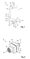
- FIG. 1 a frame 10 is shown, which has two frame parts 12, 14.
- the two frame parts 12, 14 are identical, so that only the frame part 12 is described for the sake of simplicity. Of course, it is conceivable that the frame parts 12, 14 are not identical.
- the frame part 12 is L-shaped and thus has a long leg 16 and a short leg 18, which are arranged at right angles to each other.
- a lever system 20 and a hole 21 are provided, which extends through the frame part 12.
- the lever system 20 has an actuating lever 22 and a clamping lever 24.
- the actuating lever 22 is pivotally mounted on the short leg 18 of the frame part 14.
- the clamping lever 24 is pivotally mounted at one end by means of a hinge axis.
- the hinge axis divides the operating lever 22 into two parts.
- the actuating lever 22 has an eyelet 25, which is arranged for example on the part of the actuating lever 22 farther from the frame part 12.
- the eyelet 25 is disposed on the operating lever 22 such that the eyelet 25 is aligned with the hole 21 when the frame 10 is fully closed.
- the tensioning lever 24 is elongated and made of a flat material so that it defines a plane.
- a clamping element 26 for example in the form of a pin is formed.
- a clamping surface 28 is provided, into which the clamping element 26 of the frame part 14 can engage.
- the clamping surface 28 is formed as a hook into which the clamping element formed as a pin 26 can engage.
- clamping surface 28 is provided on the clamping lever 24 and the clamping element 26 corresponding to the long leg 16 of the frame part 14th
- a contact surface 30 is formed on the inner sides of the legs 16, 18, that is the sides of the legs 16, 18, which face the respective other leg 18, 16.
- the contact surfaces 30 define a receptacle 32 in the frame 10, in the fastening elements 34 (FIG. FIG. 2 ) can be arranged and fixed.
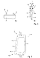
- FIG. 2 a fastener 34 is shown in perspective.
- the FIGS. 3a and 3b show a side or front view of the fastener 34th
- the fastening element 34 has a cuboid base body 36, which has two base surfaces 38 and four side surfaces 40. On the side surfaces 40 projections 42 and recesses 44 are provided to connect a plurality of fasteners 34 together.
- the base body 36 may be hollow or solid. Accordingly, the recess 44 is an opening or a recess.
- a projection 42 is arranged. As in FIG. 3a clearly visible, the projection 42 has a web 46, to which a portion 48 connects. The section 48 is in turn wider than the web 46, so that an undercut 50 is formed.
- the section 48 may, for example, be made round.
- the projection 42 extends parallel to the base surfaces 38. In the embodiment shown, it extends over half the width of the fastener 34th
- one of the recesses 44 is provided on at least one side surface 40 of the fastening element 34.
- the recess 44 may also be made elongated.
- the size and shape of the recess 44 corresponds substantially to the size and the shape of the projection 42, however, the recess 44 is slightly narrower than the width of the portion 48 executed.
- edges of the recess 44 are formed so that they can engage in the undercut 50 of the projection 42 and extend parallel to the web 46 when the projection 42 is received in the recess 44.
- the projection 42 can be inserted into the recess 44, the edge of the recess 44 and / or the portion 48 is formed elastically, in particular made of an elastic material.
- two fasteners 34 can be interconnected by the projection 42 of one of the fasteners 34 is inserted into the recess 44 of another fastener 34 and the edge of the recess 44 engages the undercut 50.
- each side surface 40 each have a projection 42 and a recess 44 is provided, which alternate, one would unwind the side surfaces 40.
- the passage of the cables or lines through the base body 36 takes place through the base surfaces 38 therethrough.
- the base surfaces 38 are preferably square and executed differently depending on the function of the fastener.
- the fastening element 34 is designed as an adapter.
- a plug 54 for example an M12 or M8 plug, is arranged on one of the base surfaces 38 and on the other base surface the coupling 54 complementary to the plug 54.
- the plug 54 is connected to the coupling 56 by electrical lines (not shown) through the base body 36.
- the plug 54 and the coupling 56 are received in the base surfaces 38 via a driving profile 57, for example a hexagon.
- a driving profile 57 for example a hexagon.
- the plug 54 and the coupling 56 can be rotated in defined steps relative to the base surfaces.
- other driving profiles are also conceivable, such as a four- or octagon, whereby other step angles are made possible.
- the plug 54 and the coupling 56 are of different types, so that a change of the cable or termination type is possible by means of the fastener.
- the plug 54 or the coupling 56 is of the type M12 and the respective other of the type M8, so that an M12-M8 adapter is realized.
- the fastening element 34 can also be designed as a plug or coupling (see. FIG. 4 ), in which on a base 38, a plug or a coupling is provided, which are connected by a cable 58, which protrudes from the other base 38, by conductors in the base body 36.
- the fastening element 34 may be designed as a simple cable grommet by an opening 59 is provided by the base body 36 from the one base 38 to the other base 38 (see. FIG. 4 ).
- FIG. 4a Several different fasteners 34 are shown, which can be interconnected.
- FIG. 4a Also shown a fastener 34 'in a second embodiment.
- the fastening element 34 ' has a larger base area 38', which corresponds approximately to four times the base area 38 of the fastening elements 34.
- projections 42 and recesses 44 are also provided, which correspond to those of the fastener 34 of the first embodiment.
- the size of the projections 42 and the recesses 44 and the distance between the projections 42 and the recesses 44 regardless of the size of the base 38, 38 ', so that fasteners 34, 34' with different base surfaces 38th , 38 'are fastened together.
- FIG. 4b are the fasteners 34, 34 'of FIG. 4a now attached to each other and form a cable gland 60 for eight cables or lines. Strictly speaking, it is not a pure cable feedthrough, since the adapter or plug cables are connected only to the cable gland 60. For the sake of simplicity, however, the term “cable feedthrough" will nevertheless be used.
- a cable feedthrough system 62 comprising a frame 10 and a grommet 60.
- the cable duct 60 is arranged in the receptacle 32 of the frame 10.
- the contact surfaces 30 of the frame parts 12, 14 are likewise formed with recesses 44, which can receive the projections 42 of the fastening elements 34, 34'.
- contact surfaces 30 are also provided with projections 42 in order to further improve the fit of the fastening elements 34, 34 'in the frame 10.
- the grommet 60 in the receptacle 32 between the two frame parts 12, 14 is arranged.
- the clamping element 26 of the clamping lever 24 is closer to the plane formed by the contact surface 30 of the short leg 18, as on a plane parallel thereto, in which the connection point between the frame part 12, 14 and the actuating lever 22 is located.
- the fastening elements 34, 34 ' are pressed against each other in such a way that they are pressed both against the adjacent fastening elements 34, 34' in the direction of the long legs 16 of the frame parts 12, 14 and against the adjacent fastening elements 34 in the direction of the short leg 18 of the frame parts 12, 14 are sealed.
- the fastening elements 34 and the cable gland 60 as a whole relative to the frame 10 in the plane of the frame slidably, as long as the frame is not completely closed, but is in a semi-closed position.
- lever systems 20 are designed such that they have a dead center, which must be overcome in order to connect the frame parts 12, 14 completely together.
- This dead center is in the embodiment shown between the positions of FIGS. 5c and 5d .
- FIG. 6a and 6b a further embodiment of a fastener 34 is shown.
- the projections 42 'and recesses 44' are different from those of the previously illustrated embodiments.
- the recess 44 ' has at least two sections 68, 70 with different widths B small , B large .
- the recess 44 ' is in the portion 68 with large marester width B greater than the width b of the hook 67, so that the hook 67 in the recess 44' can be inserted.
- the recess 44 ' has a width B small , which is narrower than the width b of the hook 67th
- the fastening elements 34 are slightly offset relative to each other, so that the hooks 67 are inserted through the sections 68 of the recesses 44 '.
- the hooks 67 are guided into the sections 70 with the smallest width, so that the fasteners 34 can not be separated from each other.
- FIG. 7 a second embodiment of the frame 10 is shown.
- the frame parts 112, 114 are made in several pieces. For simplicity, only frame part 112 will be described because the frame part 114 is identical to it.
- the frame part 112 has two end pieces 112.1, 112.2, which can be interconnected.
- the two end pieces 112.1, 112.2 correspond to the frame part 12 of the first embodiment, when they are directly connected to each other.
- the frame parts 112.1, 112.2 are connected to each other by an extension piece 72, so that in the direction of the long leg 18 longer frame 10 can be generated.
- the frame can be easily enlarged. It is also possible to adapt the frame 10 by adding a plurality of extension pieces 72 according to the required size.
Landscapes
- Engineering & Computer Science (AREA)
- Architecture (AREA)
- Civil Engineering (AREA)
- Structural Engineering (AREA)
- Installation Of Indoor Wiring (AREA)
Abstract
Die Erfindung betrifft einen Rahmen für Kabeldurchführungen (60) mit zwei Rahmenteilen (12, 14), einer Aufnahme (32) für Befestigungselemente (34; 34') und zwei Hebelsystemen (20), wobei die Rahmenteile (12, 14) Anlageflächen (30) aufweisen, die die Aufnahme (32) begrenzen, wobei jedes Hebelsystem (20) an einem Ende eines Rahmenteils (12, 14) angeordnet ist und jeweils einen Betätigungshebel (22) und einen Spannhebel (24) aufweist, die miteinander schwenkbar verbunden sind, wobei der Betätigungshebel (22) am Rahmenteil (12, 14) schwenkbar befestigt ist und der Spannhebel (24) in eine Spannfläche (28) des jeweils anderen Rahmenteils (14, 12) eingreifen kann, um die Rahmenteile (12, 14) miteinander lösbar verbinden zu können. Die Erfindung betrifft auch ein Befestigungselement für einen Rahmen (10) für Kabeldurchführungen (60), mit Grundflächen (38; 38') und Seitenflächen (40), wobei an wenigstens einer Seitenfläche (40) ein Vorsprung (42; 42') angeordnet ist und an einer nicht notwendigerweise gleichen Seitenfläche (40) eine Ausnehmung (44, 44') vorgesehen ist, in die der Vorsprung (42, 42') eines anderen Befestigungselements (34, 34') eingreifen kann, um die beiden Befestigungselemente (34; 34') aneinander zu befestigen, dadurch gekennzeichnet, dass der Querschnitt des Vorsprungs (42) einen Hinterschnitt (50) aufweist, in den der Rand der Ausnehmung (44) eines anderen Befestigungselements (34; 34') eingreifen kann. Die Erfindung betrifft schließlich ein Kabeldurchführungssystem mit einem solchen Rahmen und mehreren Befestigungselementen.The invention relates to a frame for cable bushings (60) with two frame parts (12, 14), a receptacle (32) for fastening elements (34, 34 ') and two lever systems (20), wherein the frame parts (12, 14) bear contact surfaces (30 ), which limit the receptacle (32), wherein each lever system (20) at one end of a frame part (12, 14) is arranged and each having an actuating lever (22) and a clamping lever (24) which are pivotally connected to each other, wherein the actuating lever (22) on the frame part (12, 14) is pivotally mounted and the clamping lever (24) in a clamping surface (28) of the respective other frame part (14, 12) engage to the frame parts (12, 14) releasable together to be able to connect. The invention also relates to a fastening element for a frame (10) for cable bushings (60), having base surfaces (38, 38 ') and side surfaces (40), wherein a projection (42, 42') is arranged on at least one side surface (40) and at a not necessarily the same side surface (40) has a recess (44, 44 ') is provided, in which the projection (42, 42') of another fastening element (34, 34 ') can engage to the two fastening elements (34; 34 ') to each other, characterized in that the cross section of the projection (42) has an undercut (50) into which the edge of the recess (44) of another fastening element (34; 34') can engage. Finally, the invention relates to a cable feedthrough system with such a frame and a plurality of fastening elements.
Description
Die Erfindung betrifft einen Rahmen für Kabeldurchführungen, Befestigungselemente sowie ein Kabeldurchführungssystem.The invention relates to a frame for cable penetrations, fasteners and a cable feedthrough system.
Kabeldurchführungssysteme dienen der sicheren Durchführung von Kabeln durch Wände von Gehäusen oder Schaltschränken. Um einer flexiblen Verwendung gerecht zu werden und nachträgliche Veränderungen an der Kabeldurchführung vornehmen zu können, sind modulare Kabeldurchführungen bekannt, bei denen verschiedene Kabeltüllen in einen auswechselbar Rahmen eingespannt werden können. Hierbei werden die Kabeltüllen in einen Rahmen eingeführt, der anschließend geschlossen wird.Cable gland systems are used for the safe passage of cables through the walls of enclosures or control cabinets. In order to meet a flexible use and be able to make subsequent changes to the cable gland, modular cable glands are known in which various cable grommets can be clamped in an interchangeable frame. Here, the cable grommets are inserted into a frame, which is then closed.
Bekannte modulare Kabeldurchführungssysteme sind aufwendig und schwierig zu komplettieren und zu montieren.Known modular cable entry systems are complicated and difficult to complete and assemble.
Es ist Aufgabe der Erfindung, ein modulares Kabeldurchführungssystem bereitzustellen, das auf einfache Weise die einzelnen Befestigungselemente derart aneinander befestigt, dass sich diese leicht und sicher montieren, demontieren und austauschen lassen..It is an object of the invention to provide a modular grommet system that easily fasten the individual fasteners together so that they can be easily and safely assemble, disassemble and replace.
Die Aufgabe wird gelöst durch einen Rahmen für Kabeldurchführungen, mit zwei Rahmenteilen, einer Aufnahme für Befestigungselemente und zwei Hebelsystemen, wobei die Rahmenteile Anlageflächen aufweisen, die die Aufnahme begrenzen, wobei jedes Hebelsystem an einem Ende eines Rahmenteils angeordnet ist und jeweils einen Betätigungshebel und einen Spannhebel aufweist, die miteinander schwenkbar verbunden sind, wobei der Betätigungshebel am Rahmenteil schwenkbar befestigt ist und der Spannhebel in eine Spannfläche des jeweils anderen Rahmenteils eingreifen kann, um die Rahmenteile miteinander lösbar verbinden zu können. Durch die Hebelsysteme des Rahmens ist es möglich, die in der Aufnahme des Rahmens angeordneten Befestigungselemente auf einfache Weise gegeneinander zu verspannen. Durch den Anpressdruck der Befestigungselemente untereinander dichten sich diese gegeneinander ab, sodass die gesamte Kabeldurchführung ein Eindringen von Luft und somit Feuchtigkeit verhindert.The object is achieved by a frame for cable ducts, with two frame parts, a mounting for fastening elements and two lever systems, wherein the frame parts have contact surfaces which limit the receptacle, wherein each lever system is arranged at one end of a frame part and in each case an actuating lever and a clamping lever has, which are pivotally connected to each other, wherein the actuating lever is pivotally mounted on the frame part and the clamping lever can engage in a clamping surface of the respective other frame part to the To connect frame parts with each other releasably. Due to the lever systems of the frame, it is possible to clamp the arranged in the receptacle of the frame fasteners in a simple way against each other. By the contact pressure of the fasteners with each other, these seal against each other, so that the entire cable bushing prevents ingress of air and thus moisture.
Vorzugsweise weist das Hebelsystem einen Totpunkt auf, der beim Verbinden und Lösen der beiden Rahmenteile überwunden werden muss, sodass der Rahmen gegen unbeabsichtigtes Öffnen geschützt ist, da zur Überwindung des Totpunktes Kraft aufgewendet werden muss.Preferably, the lever system has a dead center, which must be overcome when connecting and disconnecting the two frame parts, so that the frame is protected against accidental opening, as must be used to overcome the dead center force.
Beispielsweise weist jedes der beiden Rahmenteile eines der Hebelsysteme auf, wodurch die Mechanik der Hebelsysteme vereinfacht wird.For example, each of the two frame parts of one of the lever systems, whereby the mechanics of the lever systems is simplified.
In einer Ausführungsvariante sind die Rahmenteile L-förmig ausgeführt. Dadurch ist ein rechteckiger Rahmen einfach zu realisieren.In one embodiment, the frame parts are L-shaped. This makes a rectangular frame easy to realize.
Vorzugsweise sind die Hebelsysteme am kurzen Schenkel des jeweiligen Rahmenteils angeordnet. Auf diese Weise kann das Hebelsystem selbst sehr kurz ausgeführt sein.Preferably, the lever systems are arranged on the short leg of the respective frame part. In this way, the lever system itself can be made very short.
Die Spannflächen können am langen Schenkel, insbesondere am Ende des langen Schenkels, der Rahmenteile vorgesehen sein, sodass die Spannhebel einfach in die Spannflächen eingreifen können.The clamping surfaces may be provided on the long leg, in particular at the end of the long leg, the frame parts, so that the clamping lever can easily engage in the clamping surfaces.
In einer Ausführungsvariante der Erfindung bildet der Rahmen ein Rechteck, wenn sich der Rahmen in der vollständig geschlossen Stellung befindet. Auf diese Weise ist eine einfache Montage des Rahmens möglich.In one embodiment of the invention, the frame forms a rectangle when the frame is in the fully closed position. In this way, a simple mounting of the frame is possible.
Beispielsweise sind die Rahmenteile mehrstückig ausgeführt, sodass die Größe des Rahmens durch Einfügen weiterer Teile vergrößert werden kann.For example, the frame parts are made in several pieces, so that the size of the frame can be increased by inserting additional parts.
In einer Ausführungsform der Erfindung sind die Rahmenteile identisch, wodurch die Herstellungskosten des Rahmens gesenkt werden können.In one embodiment of the invention, the frame parts are identical, whereby the manufacturing cost of the frame can be reduced.
Der Verbindungshebel kann eine Öse und das Rahmenteil kann ein Loch aufweisen, wobei die Öse mit dem Loch fluchtet, wenn der Rahmen vollständig geschlossen ist. Dadurch ist es möglich, beispielsweise durch einen Stift oder eine Schraube, das Hebelsystem gegen unbeabsichtigtes Öffnen zu sichern.The connecting lever may have an eyelet and the frame part may have a hole, the eyelet being aligned with the hole when the frame is complete closed is. This makes it possible, for example by a pin or a screw to secure the lever system against accidental opening.
In einer Ausgestaltung der Erfindung ist das Hebelsystem derart ausgebildet, dass bei Betätigung des Betätigungshebels die beiden Rahmenteile aufeinander zu bewegt werden, wobei die Bewegungsrichtung der Rahmenteile schräg zu den Anlageflächen der Rahmenteile gerichtet ist. Auf diese Weise werden beim Schließen des Rahmens die Befestigungselemente sowohl in Längsrichtung des Rahmens als auch in Querrichtung des Rahmens an die angrenzenden Befestigungselemente gepresst, wodurch eine stark verbesserte Abdichtung der Kabeldurchführung ermöglicht wird. In diesem Zusammenhang ist unter "schräg" weder senkrecht noch parallel zu den von dem Rahmenschenkel definierten Richtungen zu verstehen.In one embodiment of the invention, the lever system is designed such that upon actuation of the actuating lever, the two frame parts are moved toward each other, wherein the direction of movement of the frame parts is directed obliquely to the contact surfaces of the frame parts. In this way, when closing the frame, the fasteners are pressed both in the longitudinal direction of the frame and in the transverse direction of the frame to the adjacent fasteners, whereby a much improved sealing of the cable gland is made possible. In this context, "oblique" means neither perpendicular nor parallel to the directions defined by the frame leg.
Die Aufgabe wird ferner durch ein Befestigungselement für einen Rahmen für Kabeldurchführungen gelöst, insbesondere für den bereits beschriebenen Rahmen, mit Grundflächen und Seitenflächen, wobei an wenigstens einer Seitenfläche ein Vorsprung angeordnet ist und an einer nicht notwendigerweise gleichen Seitenfläche eine Ausnehmung vorgesehen ist, in die der Vorsprung eines anderen Befestigungselements eingreifen kann, um die beiden Befestigungselemente aneinander zu befestigen, wobei der Querschnitt des Vorsprungs einen Hinterschnitt aufweist, in den der Rand der Ausnehmung eines anderen Befestigungselements eingreifen kann. Durch die Vorsprünge und Ausnehmungen ist es möglich, dass die Befestigungselemente sicher und dicht miteinander verbunden werden können, ohne dass sie dazu in einen Rahmen eingespannt werden müssen. Die Möglichkeit, die Befestigungselemente vor dem Einsetzen in den Rahmen miteinander zu verbinden, vereinfacht die Montage des Rahmens erheblich. Durch den Hinterschnitt ist eine einfache Rastverbindung zwischen den Befestigungselementen ausgebildet.The object is further achieved by a fastening element for a frame for cable penetrations, in particular for the frame already described, with base surfaces and side surfaces, wherein on at least one side surface, a projection is arranged and on a not necessarily the same side surface a recess is provided, in which the Projection of another fastener can engage to secure the two fasteners together, wherein the cross section of the projection has an undercut, in which the edge of the recess of another fastener can engage. By the projections and recesses, it is possible that the fasteners can be safely and tightly connected to each other, without having to be clamped in a frame. The ability to connect the fasteners together prior to insertion into the frame greatly simplifies assembly of the frame. By the undercut a simple locking connection between the fasteners is formed.
Vorzugsweise sind der Rand der Ausnehmung und/oder der Vorsprung aus einem elastischen Material, um ein einfaches Einrasten und Lösen zu ermöglichen.Preferably, the edge of the recess and / or the projection of an elastic material to allow easy engagement and disengagement.
In einer Ausführungsvariante ist der Vorsprung als Haken und die Ausnehmung als länglicher Schlitz ausgeführt, wobei die Ausnehmung wenigstens zwei Abschnitte mit unterschiedlicher Breite aufweist, wobei der Haken im Abschnitt mit kleinster Breite breiter als die Ausnehmung ist und der Haken im Abschnitt mit größter Breite nicht so breit wie die Ausnehmung ist. Auf diese Weise können die Befestigungselemente durch Einführen der Haken in die Ausnehmungen in Abschnitten mit größter Breite eingeführt und anschließend durch ein Verschieben der Befestigungselemente relativ zueinander entlang der Ausdehnungsrichtung der Ausnehmung verriegelt werden, solange sich die Haken in den Abschnitten der Ausnehmungen mit kleiner Breite befinden. Auf diese Weise ist eine einfache, jedoch sichere Verbindung der Befestigungselemente untereinander möglich.In one embodiment, the projection is designed as a hook and the recess as an elongated slot, wherein the recess has at least two sections with different width, wherein the Hook in the section with the smallest width is wider than the recess and the hook in the section with the largest width is not as wide as the recess. In this way, by inserting the hooks into the recesses, the fasteners can be inserted in widest-width portions and then locked by displacing the fasteners relative to each other along the direction of expansion of the recess as long as the hooks are in the portions of the small-width recesses. In this way, a simple, but secure connection of the fasteners with each other is possible.
Vorzugsweise sind an jeder Seitenfläche wenigstens eine Ausnehmung und wenigstens ein Vorsprung vorgesehen, sodass die Befestigungselemente in beliebiger Orientierung miteinander verbunden werden können.Preferably, at least one recess and at least one projection are provided on each side surface, so that the fastening elements can be connected to one another in any desired orientation.
Beispielsweise ist das Befestigungselement eine Kabeltülle, ein Stecker, eine Kupplung und/oder ein Adapter, insbesondere ein M12-M8 Adapter. Insbesondere durch die Verwendung von Adaptern, aber auch von Steckern und Kupplungen ist es möglich, besonders flexible und dichte Kabeldurchführungen bereitzustellen, an denen Leitungen ohne größere Mühe befestigt und entfernt werden können.For example, the fastener is a cable grommet, a plug, a coupling and / or an adapter, in particular an M12-M8 adapter. In particular, through the use of adapters, but also of plugs and couplings, it is possible to provide particularly flexible and tight cable glands, where lines can be attached and removed without much effort.
In einer Ausgestaltung der Erfindung ist der Stecker und/oder die Kupplung über ein Mitnahmeprofil, insbesondere ein Sechskant, in den Grundflächen aufgenommen, wodurch sich der Stecker und/oder die Kupplung in definierten Schritten verdrehen lassen. Auf diese Weise kann das Steckbild verändert werden.In one embodiment of the invention, the plug and / or the coupling is received in the base areas via a driving profile, in particular a hexagon, whereby the plug and / or the coupling can be rotated in defined steps. In this way, the plug-in image can be changed.
In einer Ausführungsvariante sind die Größe des Vorsprungs und die der Ausnehmung sowie der Abstand zwischen Vorsprung und Ausnehmung unabhängig von der Größe der Grundfläche gewählt, sodass Befestigungselemente mit verschiedenen Grundflächen aneinander befestigbar sind. Auf diese Weise lassen sich Kabeldurchführungen mit verschieden großen Befestigungselementen für Kabel verschiedener Dicken einfach realisieren.In one embodiment, the size of the projection and the recess and the distance between the projection and recess are selected independently of the size of the base, so that fasteners with different base surfaces are fastened to each other. In this way, cable entries with different sized fasteners for cables of different thicknesses can be easily realized.
Die Erfindung wird ferner durch ein Kabeldurchführungssystem mit einem Rahmen und mehreren Befestigungselementen gelöst, die in der Aufnahme des Rahmens angeordnet sind, wobei die Anlageflächen Vorsprünge und/oder Ausnehmungen aufweisen, die den Vorsprüngen und Ausnehmungen der Befestigungsmittel entsprechen, sodass die Befestigungselemente mit den Rahmenteilen verbindbar sind und bei Betätigung des Hebelsystems im Rahmen fixiert bzw. gelöst werden. Durch die Möglichkeit der Verbindung der Befestigungselemente mit dem Rahmen wird die Montage des Kabeldurchführungssystems stark vereinfacht, da ein Verkanten oder eine Fehlanordnung der Befestigungselemente verhindert wird.The invention is further achieved by a cable feedthrough system having a frame and a plurality of fastening elements, which are arranged in the receptacle of the frame, wherein the contact surfaces projections and / or Have recesses corresponding to the projections and recesses of the fastening means, so that the fastening elements are connectable to the frame parts and fixed or released in the frame when operating the lever system. The possibility of connecting the fasteners to the frame, the installation of the cable feedthrough system is greatly simplified because tilting or misalignment of the fasteners is prevented.
Vorzugsweise sind die Befestigungselemente einzeln oder zusammen gegenüber dem Rahmen in der Ebene des Rahmens verschiebbar, wenn sich der Rahmen in einer halb-geschlossenen Stellung befindet, wodurch das Verschließen des Rahmens vereinfacht wird. Dabei sind die Befestigungselemente sowohl entlang der Längsrichtung als auch der Querrichtung des Rahmens verschiebbar und nicht lediglich nur entlang einer der Richtungen des Rahmens.Preferably, the fasteners are individually or together displaceable relative to the frame in the plane of the frame when the frame is in a semi-closed position, thereby facilitating the closing of the frame. In this case, the fastening elements are displaceable both along the longitudinal direction and the transverse direction of the frame and not only along only one of the directions of the frame.
Weitere Merkmale und Vorteile der Erfindung ergeben sich aus der nachfolgenden Beschreibung und aus den beigefügten Zeichnungen, auf die Bezug genommen wird. In den Zeichnungen zeigen:
-
Figur 1 einen erfindungsgemäßen Rahmen in geöffneter Stellung in Draufsicht, -
Figur 2 ein erfindungsgemäßes Befestigungselement in perspektivischer Ansicht, -
Figur 3a das Befestigungselement nachFigur 2 in Seitenansicht, -
Figur 3b das Befestigungselement nachFigur 2 in Frontansicht, -
Figur 4a mehrere unverbunden erfindungsgemäße Befestigungselemente in perspektivischer Ansicht, -
Figur 4b die Befestigungselemente nachFigur 4a in perspektivischer Ansicht miteinander verbunden, - die
Figuren 5a bis 5d ein erfindungsgemäßes Kabeldurchführungssystem mit dem Rahmen nachFigur 1 und den Befestigungselementen nachFigur 4b in verschiedenen Stellungen während des Schließens des Rahmens, -
Figur 6a einen Ausschnitt einer zweiten Ausführungsform eines erfindungsgemäßen Befestigungselementes in Frontansicht, -
Figur 6b das Befestigungselement nachFigur 6a in Seitenansicht, und -
Figur 7 eine weitere Ausführungsform eines erfindungsgemäßen Rahmens in Draufsicht.
-
FIG. 1 a frame according to the invention in the open position in plan view, -
FIG. 2 an inventive fastener in a perspective view, -
FIG. 3a the fastener afterFIG. 2 in side view, -
FIG. 3b the fastener afterFIG. 2 in front view, -
FIG. 4a several unconnected fastening elements according to the invention in a perspective view, -
FIG. 4b the fasteners afterFIG. 4a connected in perspective view, - the
FIGS. 5a to 5d an inventive cable duct system with the frameFIG. 1 and the fasteners afterFIG. 4b in different positions during the closing of the frame, -
FIG. 6a a detail of a second embodiment of a fastener according to the invention in front view, -
FIG. 6b the fastener afterFIG. 6a in side view, and -
FIG. 7 a further embodiment of a frame according to the invention in plan view.
In
In der gezeigten Ausführungsform sind die beiden Rahmenteile 12, 14 identisch, sodass zur Vereinfachung lediglich das Rahmenteil 12 beschrieben wird. Selbstverständlich ist es denkbar, dass die Rahmenteile 12, 14 nicht identisch ausgeführt sind.In the embodiment shown, the two
Das Rahmenteil 12 ist L-förmig ausgeführt und hat somit einen langen Schenkel 16 und einen kurzen Schenkel 18, die zueinander im rechten Winkel angeordnet sind.The
Am kurzen Schenkel 18 sind ein Hebelsystem 20 und ein Loch 21 vorgesehen, dass sich durch das Rahmenteil 12 erstreckt.On the
Das Hebelsystem 20 weist einen Betätigungshebel 22 und einen Spannhebel 24 auf.The
Der Betätigungshebel 22 ist am kurzen Schenkel 18 des Rahmenteils 14 schwenkbar angeordnet. Im mittleren Abschnitt des Betätigungshebels 22 ist der Spannhebel 24 mit einem Ende mittels einer Gelenkachse schwenkbar angebracht. Die Gelenkachse teilt den Betätigungshebel 22 in zwei Teile.The actuating
Zudem weist der Betätigungshebel 22 eine Öse 25 auf, die beispielsweise auf dem vom Rahmenteil 12 weiter entfernten Teil des Betätigungshebels 22 angeordnet ist.In addition, the actuating
Die Öse 25 ist am Betätigungshebel 22 derart angeordnet, dass die Öse 25 mit dem Loch 21 fluchtet, wenn der Rahmen 10 vollständig geschlossen ist.The
Der Spannhebel 24 ist beispielsweise länglich und aus einem Flachmaterial hergestellt, sodass er eine Ebene definiert.For example, the tensioning
An dem Ende des Spannhebels 24, der nicht mit dem Betätigungshebel 22 verbunden ist, ist ein Spannelement 26, beispielsweise in Form eines Stiftes, ausgebildet.At the end of the clamping
Am langen Schenkel 16 des Rahmenteils 12 ist eine Spannfläche 28 vorgesehen, in die das Spannelement 26 des Rahmenteils 14 eingreifen kann. In der gezeigten Ausführungsform ist die Spannfläche 28 als Haken ausgebildet, in die das als Stift ausgebildete Spannelement 26 eingreifen kann.On the
Selbstverständlich ist es denkbar, dass die Spannfläche 28 am Spannhebel 24 vorgesehen ist und das Spannelement 26 entsprechend am langen Schenkel 16 des Rahmenteils 14.Of course, it is conceivable that the clamping
An den Innenseiten der Schenkel 16, 18, das heißt den Seiten der Schenkel 16, 18, die dem jeweiligen anderen Schenkel 18, 16 zugewandt sind, ist eine Anlagefläche 30 ausgebildet. Die Anlageflächen 30 begrenzen eine Aufnahme 32 im Rahmen 10, in der Befestigungselemente 34 (
In
Das Befestigungselement 34 weist einen quaderförmigen Grundkörper 36 auf, der zwei Grundflächen 38 und vier Seitenflächen 40 hat. An den Seitenflächen 40 sind Vorsprünge 42 und Ausnehmungen 44 vorgesehen, um mehrere Befestigungselemente 34 miteinander verbinden zu können.The
Der Grundkörper 36 kann hohl oder als Vollmaterial ausgeführt sein. Entsprechend ist die Ausnehmung 44 eine Öffnung oder eine Vertiefung.The
An wenigstens einer Seitenfläche 40 ist ein Vorsprung 42 angeordnet. Wie in
Der Abschnitt 48 kann beispielsweise rund ausgeführt sein.The
Wie in
Weiterhin ist an wenigstens einer Seitenfläche 40 des Befestigungselements 34 eine der Ausnehmungen 44 vorgesehen.Furthermore, one of the
Die Ausnehmung 44 kann ebenfalls länglich ausgeführt sein. Die Größe und Form der Ausnehmung 44 entspricht dabei im Wesentlichen der Größe und der Form des Vorsprungs 42, jedoch ist die Ausnehmung 44 etwas schmaler als die Breite des Abschnitts 48 ausgeführt.The
Die Ränder der Ausnehmung 44 sind derart ausgebildet, dass sie in den Hinterschnitt 50 des Vorsprungs 42 eingreifen können und erstrecken sich parallel zum Steg 46, wenn der Vorsprung 42 in der Ausnehmung 44 aufgenommen ist.The edges of the
Damit der Vorsprung 42 in die Ausnehmung 44 eingeführt werden kann, ist der Rand der Ausnehmung 44 und/oder der Abschnitt 48 elastisch ausgebildet, insbesondere aus einem elastischen Material gefertigt. Somit können zwei Befestigungselemente 34 miteinander verbunden werden, indem der Vorsprung 42 eines der Befestigungselemente 34 in die Ausnehmung 44 eines anderen Befestigungselementes 34 eingeführt wird und der Rand der Ausnehmung 44 in den Hinterschnitt 50 greift.So that the
Beispielsweise sind pro Seitenfläche 40 je ein Vorsprung 42 und eine Ausnehmung 44 vorgesehen, die sich abwechseln, würde man die Seitenflächen 40 abwickeln.For example, per
Die Durchführung der Kabel bzw. der Leitungen durch den Grundkörper 36 erfolgt durch die Grundflächen 38 hindurch.The passage of the cables or lines through the
Die Grundflächen 38 sind vorzugsweise quadratisch und je nach Funktion des Befestigungselements unterschiedlich ausgeführt.The base surfaces 38 are preferably square and executed differently depending on the function of the fastener.
In den
Der Stecker 54 und die Kupplung 56 sind über ein Mitnahmeprofil 57, beispielsweise ein Sechskant, in den Grundflächen 38 aufgenommen. So können der Stecker 54 und die Kupplung 56 in definierten Schritten gegenüber den Grundflächen verdreht werden. Denkbar sind selbstverständlich auch andere Mitnahmeprofile wie ein Vier- oder Achtkant, wodurch andere Schrittwinkel ermöglicht werden.The
Denkbar ist selbstverständlich auch, dass der Stecker 54 und die Kupplung 56 unterschiedlichen Typs sind, sodass mithilfe des Befestigungselements ein Wechsel des Kabel- bzw. Abschlusstyps möglich ist. Vorzugsweise ist der Stecker 54 oder die Kupplung 56 vom Typ M12 und der jeweilige andere vom Typ M8, sodass ein M12-M8-Adapter realisiert ist.It is of course also conceivable that the
Auch sind weitere Typen von Befestigungselementen 34 denkbar. So kann das Befestigungselement 34 auch als Stecker bzw. Kupplung ausgeführt sein (vgl.
Ebenso kann das Befestigungselement 34 als einfache Kabeltülle ausgeführt sein, indem von der einen Grundfläche 38 zur anderen Grundfläche 38 ein Durchbruch 59 durch den Grundkörper 36 vorgesehen ist (vgl.
In
Neben den Befestigungselementen 34 gemäß der Ausführungsform der
Das Befestigungselement 34' weist eine größere Grundfläche 38' auf, die in etwa dem Vierfachen der Grundfläche 38 der Befestigungselemente 34 entspricht.The fastening element 34 'has a larger base area 38', which corresponds approximately to four times the
Entsprechend sind im Befestigungselement 34' vier Durchbrüche, Stecker, Kupplungen und/oder Adapter vorgesehen.Accordingly, four openings, connectors, couplings and / or adapters are provided in the fastening element 34 '.
An den Seitenflächen 40 sind ebenfalls Vorsprünge 42 und Ausnehmungen 44 vorgesehen, die denen des Befestigungselements 34 der ersten Ausführungsform entsprechen.On the side surfaces 40
Bei allen Ausführungsformen des Befestigungselements 34 ist die Größe der Vorsprünge 42 und die der Ausnehmungen 44 sowie der Abstand zwischen den Vorsprüngen 42 und der Ausnehmungen 44 unabhängig von der Größe der Grundfläche 38, 38', sodass auch Befestigungselemente 34, 34' mit verschiedenen Grundflächen 38, 38' aneinander befestigbar sind.In all embodiments of the
In
Aufgrund der Verbindung der Vorsprünge 42 mit den Ausnehmungen 44 halten die Befestigungselemente 34, 34' aneinander, ohne in einen Rahmen 10 eingespannt zu sein.Due to the connection of the
In den
Dabei ist die Kabeldurchführung 60 in der Aufnahme 32 des Rahmens 10 angeordnet.In this case, the
Zur Verbindung der einzelnen Befestigungselemente 34, 34' mit den Rahmenteilen 12, 14 sind die Anlageflächen 30 der Rahmenteile 12, 14 ebenfalls mit Ausnehmungen 44 ausgebildet, die die Vorsprünge 42 der Befestigungselemente 34, 34' aufnehmen können.To connect the
Denkbar ist weiterhin, dass die Anlageflächen 30 auch mit Vorsprüngen 42 versehen sind, um den Sitz der Befestigungselemente 34, 34' im Rahmen 10 weiter zu verbessern.It is also conceivable that the contact surfaces 30 are also provided with
Das Verbinden der beiden Rahmenteile 12, 14 und somit das Schließen des Rahmens 10 und Fixieren der Befestigungselemente 34, 34' erfolgt wie folgt.The connection of the two
Zunächst wird, nachdem die Befestigungselemente 34, 34' zur Kabeldurchführung 60 zusammengesteckt wurde, die Kabeldurchführung 60 in der Aufnahme 32 zwischen den beiden Rahmenteilen 12, 14 angeordnet.First, after the
Daraufhin werden die Spannelemente 26 der Spannhebel 24 der Rahmenteile 12, 14 mit den Spannflächen 28 des jeweils anderen Rahmenteils 14, 12 in Eingriff gebracht, sodass die Kabeldurchführung 60 nun vollständig von den Rahmenteilen 12, 14 umgeben ist (vgl.
In dieser Stellung des Hebelsystems 20 liegt das Spannelement 26 des Spannhebels 24 näher an der Ebene, die durch die Anlagefläche 30 des kurzen Schenkels 18 gebildet wird, als an einer dazu parallelen Ebene, in der der Verbindungspunkt zwischen dem Rahmenteil 12, 14 und dem Betätigungshebel 22 liegt.In this position of the
Zum Schließen bzw. vollständigen Verbinden des Rahmens 10 werden nun die beiden Betätigungshebel 22 mit einer Kraft beaufschlagt, sodass der Betätigungshebel 22 im Uhrzeigersinn, in Bezug auf die Darstellung der
Durch die Betätigung des Betätigungshebels 22 wird auch der Spannhebel 24 bewegt, wodurch die beiden Rahmenteile 12, 14 aufeinander zu gezogen werden. Die Bewegung der beiden Rahmenteile erfolgt dabei schräg in Bezug auf die Anlageflächen 30 der beiden Schenkel 16, 18.By operating the operating
Dadurch werden die Befestigungselemente 34, 34' derart gegeneinandergepresst, dass sie sowohl gegen die angrenzenden Befestigungselemente 34, 34' in Richtung der langen Schenkel 16 der Rahmenteile 12, 14 als auch gegen die angrenzenden Befestigungselemente 34 in Richtung des kurzen Schenkels 18 der Rahmenteile 12, 14 abgedichtet werden.As a result, the
Auf diese Weise wird gewährleistet, dass die Kabeldurchführung 60 dicht ist und durch sie keine Feuchtigkeit dringen kann.In this way it is ensured that the
Darüber hinaus sind, wie in den
Beispielsweis sind die Stellung nach den
Zudem sind die Hebelsysteme 20 derart ausgebildet, dass sie einen Totpunkt aufweisen, der überwunden werden muss, um die Rahmenteile 12, 14 vollständig miteinander zu verbinden.In addition, the
Dieser Totpunkt liegt in der gezeigten Ausführungsform zwischen den Stellungen der
Das Überschreiten des Totpunktes beim Schließen des Rahmens 10 führt dazu, dass der Betätigungshebel 22 in die Stellung der
Die Befestigungselemente 34, 34' sind nun derart miteinander verspannt, dass sie die Kabeldurchführung 60 nahezu luftdicht abschließen.The
In der Stellung der
In den
Die Vorsprünge 42' sind in dieser Ausführungsform schmal ausgeführt und weisen an ihren den Seitenflächen 40 abgewandten Enden Haken 67 auf. Die Ausnehmungen 44' sind als länglicher Schlitz ausgebildet.The projections 42 'are narrow in this embodiment and have
Die Ausnehmung 44' weist wenigstens zwei Abschnitte 68, 70 mit verschiedenen Breiten Bklein, Bgroß auf. Dabei ist die Ausnehmung 44' in dem Abschnitt 68 mit weitester Breite Bgroß größer als die Breite b des Hakens 67, sodass der Haken 67 in die Ausnehmung 44' eingeführt werden kann. In den Abschnitten 70 mit geringerer Breite Bklein weist die Ausnehmung 44' eine Breite Bklein auf, die schmaler ist als die Breite b des Hakens 67.The recess 44 'has at least two
Es können an einer Seitenfläche 40 auch zwei Vorsprünge 42' vorgesehen sein. In diesem Fall weist die Ausnehmung 44' je zwei Abschnitte 68 mit größter und zwei Abschnitte 70 mit geringster Breite auf.It can be provided on a
Zum Verbinden werden die Befestigungselemente 34 leicht versetzt einander angenähert, sodass die Haken 67 durch die Abschnitte 68 der Ausnehmungen 44' eingeführt werden. Durch Verschieben der Befestigungselemente 34 entlang der Längsachse der Seitenfläche, die aneinander anliegen, werden die Haken 67 in die Abschnitte 70 mit geringster Breite geführt, sodass sich die Befestigungselemente 34 nicht mehr voneinander lösen lassen.For connection, the
In
In Unterschied zur ersten Ausführungsform sind die Rahmenteile 112, 114 mehrstückig ausgeführt. Zur Vereinfachung wird nur Rahmenteil 112 beschrieben, da das Rahmenteil 114 zu diesem identisch ist.In contrast to the first embodiment, the
Das Rahmenteil 112 weist zwei Endstücke 112.1, 112.2 auf, die miteinander verbunden werden können. Die beiden Endstücke 112.1, 112.2 entsprechen dem Rahmenteil 12 der ersten Ausführungsform, wenn sie direkt miteinander verbunden sind.The
In
Auf diese Weise kann der Rahmen auf einfache Weise vergrößert werden. Auch ist es möglich, den Rahmen 10 durch das Hinzufügen mehrerer Verlängerungsstücke 72 entsprechend der benötigten Baugröße anzupassen.In this way, the frame can be easily enlarged. It is also possible to adapt the
Claims (20)
Applications Claiming Priority (1)
| Application Number | Priority Date | Filing Date | Title |
|---|---|---|---|
| DE102014102790.6A DE102014102790A1 (en) | 2014-03-03 | 2014-03-03 | Frame for cable glands, fasteners and cable entry system |
Publications (2)
| Publication Number | Publication Date |
|---|---|
| EP2916409A2 true EP2916409A2 (en) | 2015-09-09 |
| EP2916409A3 EP2916409A3 (en) | 2015-12-23 |
Family
ID=52596788
Family Applications (1)
| Application Number | Title | Priority Date | Filing Date |
|---|---|---|---|
| EP15156718.7A Withdrawn EP2916409A3 (en) | 2014-03-03 | 2015-02-26 | Frame for cable feedthroughs, fastening elements and cable feedthrough system |
Country Status (2)
| Country | Link |
|---|---|
| EP (1) | EP2916409A3 (en) |
| DE (1) | DE102014102790A1 (en) |
Cited By (5)
| Publication number | Priority date | Publication date | Assignee | Title |
|---|---|---|---|---|
| WO2018189182A1 (en) * | 2017-04-10 | 2018-10-18 | Igus Gmbh | Strain relief for quick assembly for a cable carrier |
| EP3404789A1 (en) * | 2017-05-16 | 2018-11-21 | Aetec OOO | Frame for cable feedthroughs and modules of the feedthroughs |
| WO2020089031A1 (en) * | 2018-10-29 | 2020-05-07 | Icotek Project Gmbh & Co. Kg | Cable feedthrough |
| WO2020207796A1 (en) * | 2019-04-10 | 2020-10-15 | Icotek Project Gmbh & Co. Kg | Device for introducing cables through an opening |
| CN114080729A (en) * | 2019-07-09 | 2022-02-22 | 库卡德国有限公司 | Cable through piece for control cabinet |
Family Cites Families (10)
| Publication number | Priority date | Publication date | Assignee | Title |
|---|---|---|---|---|
| DE7921514U1 (en) * | 1979-07-27 | 1979-10-25 | Upat Max Langensiepen Kg | Frame for holding stacked boxes together or the like |
| DE8313278U1 (en) * | 1983-05-05 | 1983-11-03 | Steindorff, Dieter, 3360 Osterode | Frame construction for attaching furniture to a mobile home |
| DE3727160C1 (en) * | 1987-08-14 | 1988-09-08 | Plastoform Gmbh & Co Kg | Lead-through for cables through a wall opening |
| GB2337870A (en) * | 1998-04-29 | 1999-12-01 | Nokia Telecommunications Oy | Modular cable entry system |
| DE19959151C1 (en) * | 1999-12-08 | 2001-08-09 | Klein Guenther Industriebedarf | Device for the sealed passage of cables, lines or pipes in ceiling or wall openings in high-rise buildings |
| DE102005017689A1 (en) * | 2005-04-08 | 2006-10-12 | Lapp Engineering & Co. | Cable gland and cable gland system |
| DE102010037465A1 (en) * | 2010-09-10 | 2012-03-15 | Phoenix Contact Gmbh & Co. Kg | Frame for cable entry systems and frame parts therefor |
| DE102010037463A1 (en) * | 2010-09-10 | 2012-03-15 | Phoenix Contact Gmbh & Co. Kg | Frame of a cable entry system and cable grommet for this |
| DE202010008917U1 (en) * | 2010-10-28 | 2012-01-30 | SCHÜCO International KG | Frame construction and insertion tool |
| DE102012007460A1 (en) * | 2012-04-13 | 2013-10-17 | Pflitsch Gmbh & Co. Kg | Device for laying long molded parts through device walls |
-
2014
- 2014-03-03 DE DE102014102790.6A patent/DE102014102790A1/en not_active Ceased
-
2015
- 2015-02-26 EP EP15156718.7A patent/EP2916409A3/en not_active Withdrawn
Non-Patent Citations (1)
| Title |
|---|
| None |
Cited By (10)
| Publication number | Priority date | Publication date | Assignee | Title |
|---|---|---|---|---|
| WO2018189182A1 (en) * | 2017-04-10 | 2018-10-18 | Igus Gmbh | Strain relief for quick assembly for a cable carrier |
| CN110800179A (en) * | 2017-04-10 | 2020-02-14 | 易格斯有限公司 | Tension relief for quick assembly of energy-guiding chains |
| US11600981B2 (en) | 2017-04-10 | 2023-03-07 | Igus Gmbh | Strain relief for quick assembly for a cable carrier |
| EP3404789A1 (en) * | 2017-05-16 | 2018-11-21 | Aetec OOO | Frame for cable feedthroughs and modules of the feedthroughs |
| WO2020089031A1 (en) * | 2018-10-29 | 2020-05-07 | Icotek Project Gmbh & Co. Kg | Cable feedthrough |
| US11942772B2 (en) | 2018-10-29 | 2024-03-26 | Icotek Project Gmbh & Co. Kg | Cable bushing |
| WO2020207796A1 (en) * | 2019-04-10 | 2020-10-15 | Icotek Project Gmbh & Co. Kg | Device for introducing cables through an opening |
| CN113950783A (en) * | 2019-04-10 | 2022-01-18 | 伊科泰克项目有限公司 | Device for introducing a line through an opening |
| US20220216649A1 (en) * | 2019-04-10 | 2022-07-07 | Icotek Project Gmbh & Co. Kg | Device for introducing cables through an opening |
| CN114080729A (en) * | 2019-07-09 | 2022-02-22 | 库卡德国有限公司 | Cable through piece for control cabinet |
Also Published As
| Publication number | Publication date |
|---|---|
| DE102014102790A1 (en) | 2015-09-03 |
| EP2916409A3 (en) | 2015-12-23 |
Similar Documents
| Publication | Publication Date | Title |
|---|---|---|
| DE3903839C2 (en) | ||
| DE102008017423B4 (en) | Surge protection device | |
| WO2015185511A2 (en) | Electric device | |
| EP2916409A2 (en) | Frame for cable feedthroughs, fastening elements and cable feedthrough system | |
| DE102015222561B4 (en) | Holding frame for holding connector modules | |
| DE102011051291A1 (en) | Plug connector with chamber block and contact protection | |
| EP1655813A1 (en) | Attachment for electrical connector | |
| DE102010037465A1 (en) | Frame for cable entry systems and frame parts therefor | |
| EP3679631B1 (en) | Plug connector with locking hooks for securing the contact support of the plug connector in the outer housing of the plug connector | |
| WO2013060772A1 (en) | Two-part electrical plug connector | |
| DE102012101813B3 (en) | Connectors | |
| EP2067212B1 (en) | Electric plug connector having a guiding | |
| DE102016104082B3 (en) | Electrical plug-in device with a latching mechanism | |
| WO2019161848A1 (en) | Plug connector comprising polarisation element, and system and method for mounting, for plugging. and for separating said plug connector | |
| DE102016217456B3 (en) | Arrangement for an electrical connector and plug connector with a contact housing, housing and securing element | |
| EP0901190A2 (en) | Cable-plug-leadthrough system | |
| DE102021204905A1 (en) | Use of an enclosure to prevent a pipe or cable from exiting a first cable connector, kit, assembly and method of assembling the same | |
| DE10393723B4 (en) | Plug connection and assembly method for producing at least one connection through an opening in a partition wall | |
| DE102017115013B3 (en) | Contact carrier arrangement and method for mounting the contact carrier arrangement | |
| DE102020115863A1 (en) | Connector with locking means that can be selected from a group | |
| DE112018007584T5 (en) | Terminal block assembly | |
| EP2639912B1 (en) | Device installation socket for device installation channels and device installation channel comprising same | |
| DE102011002794A1 (en) | Connector, mating connector and connector assembly with clamping surfaces and fixing means | |
| EP2263292A1 (en) | Apparatus for strain relief | |
| DE202014100373U1 (en) | installation box |
Legal Events
| Date | Code | Title | Description |
|---|---|---|---|
| PUAI | Public reference made under article 153(3) epc to a published international application that has entered the european phase |
Free format text: ORIGINAL CODE: 0009012 |
|
| AK | Designated contracting states |
Kind code of ref document: A2 Designated state(s): AL AT BE BG CH CY CZ DE DK EE ES FI FR GB GR HR HU IE IS IT LI LT LU LV MC MK MT NL NO PL PT RO RS SE SI SK SM TR |
|
| AX | Request for extension of the european patent |
Extension state: BA ME |
|
| PUAL | Search report despatched |
Free format text: ORIGINAL CODE: 0009013 |
|
| AK | Designated contracting states |
Kind code of ref document: A3 Designated state(s): AL AT BE BG CH CY CZ DE DK EE ES FI FR GB GR HR HU IE IS IT LI LT LU LV MC MK MT NL NO PL PT RO RS SE SI SK SM TR |
|
| AX | Request for extension of the european patent |
Extension state: BA ME |
|
| RIC1 | Information provided on ipc code assigned before grant |
Ipc: H02G 3/22 20060101AFI20151119BHEP |
|
| 17P | Request for examination filed |
Effective date: 20160603 |
|
| RBV | Designated contracting states (corrected) |
Designated state(s): AL AT BE BG CH CY CZ DE DK EE ES FI FR GB GR HR HU IE IS IT LI LT LU LV MC MK MT NL NO PL PT RO RS SE SI SK SM TR |
|
| 17Q | First examination report despatched |
Effective date: 20180928 |
|
| GRAP | Despatch of communication of intention to grant a patent |
Free format text: ORIGINAL CODE: EPIDOSNIGR1 |
|
| INTG | Intention to grant announced |
Effective date: 20200316 |
|
| STAA | Information on the status of an ep patent application or granted ep patent |
Free format text: STATUS: THE APPLICATION IS DEEMED TO BE WITHDRAWN |
|
| 18D | Application deemed to be withdrawn |
Effective date: 20200728 |