EP2911435A1 - Apparatuses, methods and computer programs for determining information related to a path direction and for a transceiver of a communication device - Google Patents
Apparatuses, methods and computer programs for determining information related to a path direction and for a transceiver of a communication device Download PDFInfo
- Publication number
- EP2911435A1 EP2911435A1 EP14305250.4A EP14305250A EP2911435A1 EP 2911435 A1 EP2911435 A1 EP 2911435A1 EP 14305250 A EP14305250 A EP 14305250A EP 2911435 A1 EP2911435 A1 EP 2911435A1
- Authority
- EP
- European Patent Office
- Prior art keywords
- information related
- transceiver
- operable
- module
- path direction
- Prior art date
- Legal status (The legal status is an assumption and is not a legal conclusion. Google has not performed a legal analysis and makes no representation as to the accuracy of the status listed.)
- Granted
Links
- 238000004891 communication Methods 0.000 title claims abstract description 122
- 238000000034 method Methods 0.000 title claims abstract description 61
- 238000004590 computer program Methods 0.000 title claims abstract description 17
- 238000012545 processing Methods 0.000 claims abstract description 105
- 230000007613 environmental effect Effects 0.000 claims abstract description 58
- 230000008569 process Effects 0.000 claims abstract description 8
- 238000005516 engineering process Methods 0.000 claims description 28
- 238000004422 calculation algorithm Methods 0.000 claims description 12
- 230000001413 cellular effect Effects 0.000 claims description 10
- 230000005540 biological transmission Effects 0.000 description 14
- 238000010586 diagram Methods 0.000 description 14
- 238000010295 mobile communication Methods 0.000 description 9
- 230000006870 function Effects 0.000 description 8
- 230000015654 memory Effects 0.000 description 6
- 230000001419 dependent effect Effects 0.000 description 5
- 238000005457 optimization Methods 0.000 description 5
- 238000007726 management method Methods 0.000 description 4
- 238000003491 array Methods 0.000 description 3
- 230000006872 improvement Effects 0.000 description 3
- 238000012937 correction Methods 0.000 description 2
- 238000013500 data storage Methods 0.000 description 2
- 238000009434 installation Methods 0.000 description 2
- 230000007246 mechanism Effects 0.000 description 2
- 238000012986 modification Methods 0.000 description 2
- 230000004048 modification Effects 0.000 description 2
- 229920000954 Polyglycolide Polymers 0.000 description 1
- 230000001133 acceleration Effects 0.000 description 1
- 230000003044 adaptive effect Effects 0.000 description 1
- 230000002238 attenuated effect Effects 0.000 description 1
- 230000003190 augmentative effect Effects 0.000 description 1
- 238000004364 calculation method Methods 0.000 description 1
- 230000006735 deficit Effects 0.000 description 1
- 230000001066 destructive effect Effects 0.000 description 1
- 230000000694 effects Effects 0.000 description 1
- 230000003993 interaction Effects 0.000 description 1
- 238000011835 investigation Methods 0.000 description 1
- 230000007774 longterm Effects 0.000 description 1
- 230000003287 optical effect Effects 0.000 description 1
- 230000008520 organization Effects 0.000 description 1
- 229920000747 poly(lactic acid) Polymers 0.000 description 1
- 235000010409 propane-1,2-diol alginate Nutrition 0.000 description 1
- 238000011160 research Methods 0.000 description 1
- 238000004088 simulation Methods 0.000 description 1
- 239000007787 solid Substances 0.000 description 1
- 230000003068 static effect Effects 0.000 description 1
- 238000012360 testing method Methods 0.000 description 1
- 238000012549 training Methods 0.000 description 1
- 238000012546 transfer Methods 0.000 description 1
- 230000007704 transition Effects 0.000 description 1
Images


Classifications
-
- H—ELECTRICITY
- H04—ELECTRIC COMMUNICATION TECHNIQUE
- H04W—WIRELESS COMMUNICATION NETWORKS
- H04W16/00—Network planning, e.g. coverage or traffic planning tools; Network deployment, e.g. resource partitioning or cells structures
- H04W16/24—Cell structures
- H04W16/28—Cell structures using beam steering
-
- G—PHYSICS
- G01—MEASURING; TESTING
- G01S—RADIO DIRECTION-FINDING; RADIO NAVIGATION; DETERMINING DISTANCE OR VELOCITY BY USE OF RADIO WAVES; LOCATING OR PRESENCE-DETECTING BY USE OF THE REFLECTION OR RERADIATION OF RADIO WAVES; ANALOGOUS ARRANGEMENTS USING OTHER WAVES
- G01S5/00—Position-fixing by co-ordinating two or more direction or position line determinations; Position-fixing by co-ordinating two or more distance determinations
- G01S5/02—Position-fixing by co-ordinating two or more direction or position line determinations; Position-fixing by co-ordinating two or more distance determinations using radio waves
- G01S5/0205—Details
- G01S5/0218—Multipath in signal reception
-
- H—ELECTRICITY
- H04—ELECTRIC COMMUNICATION TECHNIQUE
- H04B—TRANSMISSION
- H04B7/00—Radio transmission systems, i.e. using radiation field
- H04B7/02—Diversity systems; Multi-antenna system, i.e. transmission or reception using multiple antennas
- H04B7/04—Diversity systems; Multi-antenna system, i.e. transmission or reception using multiple antennas using two or more spaced independent antennas
- H04B7/06—Diversity systems; Multi-antenna system, i.e. transmission or reception using multiple antennas using two or more spaced independent antennas at the transmitting station
- H04B7/0613—Diversity systems; Multi-antenna system, i.e. transmission or reception using multiple antennas using two or more spaced independent antennas at the transmitting station using simultaneous transmission
- H04B7/0615—Diversity systems; Multi-antenna system, i.e. transmission or reception using multiple antennas using two or more spaced independent antennas at the transmitting station using simultaneous transmission of weighted versions of same signal
- H04B7/0617—Diversity systems; Multi-antenna system, i.e. transmission or reception using multiple antennas using two or more spaced independent antennas at the transmitting station using simultaneous transmission of weighted versions of same signal for beam forming
-
- H—ELECTRICITY
- H04—ELECTRIC COMMUNICATION TECHNIQUE
- H04B—TRANSMISSION
- H04B7/00—Radio transmission systems, i.e. using radiation field
- H04B7/02—Diversity systems; Multi-antenna system, i.e. transmission or reception using multiple antennas
- H04B7/04—Diversity systems; Multi-antenna system, i.e. transmission or reception using multiple antennas using two or more spaced independent antennas
- H04B7/06—Diversity systems; Multi-antenna system, i.e. transmission or reception using multiple antennas using two or more spaced independent antennas at the transmitting station
- H04B7/0686—Hybrid systems, i.e. switching and simultaneous transmission
- H04B7/0695—Hybrid systems, i.e. switching and simultaneous transmission using beam selection
-
- H—ELECTRICITY
- H04—ELECTRIC COMMUNICATION TECHNIQUE
- H04B—TRANSMISSION
- H04B7/00—Radio transmission systems, i.e. using radiation field
- H04B7/02—Diversity systems; Multi-antenna system, i.e. transmission or reception using multiple antennas
- H04B7/04—Diversity systems; Multi-antenna system, i.e. transmission or reception using multiple antennas using two or more spaced independent antennas
- H04B7/08—Diversity systems; Multi-antenna system, i.e. transmission or reception using multiple antennas using two or more spaced independent antennas at the receiving station
- H04B7/0837—Diversity systems; Multi-antenna system, i.e. transmission or reception using multiple antennas using two or more spaced independent antennas at the receiving station using pre-detection combining
- H04B7/0842—Weighted combining
- H04B7/086—Weighted combining using weights depending on external parameters, e.g. direction of arrival [DOA], predetermined weights or beamforming
-
- H—ELECTRICITY
- H04—ELECTRIC COMMUNICATION TECHNIQUE
- H04W—WIRELESS COMMUNICATION NETWORKS
- H04W4/00—Services specially adapted for wireless communication networks; Facilities therefor
- H04W4/02—Services making use of location information
- H04W4/029—Location-based management or tracking services
-
- H—ELECTRICITY
- H04—ELECTRIC COMMUNICATION TECHNIQUE
- H04W—WIRELESS COMMUNICATION NETWORKS
- H04W64/00—Locating users or terminals or network equipment for network management purposes, e.g. mobility management
Definitions
- Embodiments relate to apparatuses, methods and computer programs for determining information related to a path direction and for a transceiver of a communication device, more particularly but not exclusively, to radio frequency transmission in a millimeter-wavelength range.
- Communication in higher frequency ranges than used by today's classical wireless systems, like 11-300GHz with so-called mm-Waves, may face the challenge to exploit Line-Of-Sight (LOS), Non LOS (NLOS), or reflected paths for e.g. small cell backhaul or access applications which may use high gain antennas with steerable beams to overcome the high pathloss.
- LOS Line-Of-Sight
- NLOS Non LOS
- reflected paths for e.g. small cell backhaul or access applications which may use high gain antennas with steerable beams to overcome the high pathloss.
- Due to the specific mm-wave propagation properties the channel may often consist only of one or two spatially separated paths, and a connection between a transmitter and a receiver may only be established when pointing a main lobe of an antenna pattern or beam of a high gain and narrow Half Power Beam Width (HPBW), for example using an antenna array, into the direction of the signal.
- HPBW Half Power Beam Width
- the direction of the strongest path might not be known and a beam might not be steered initially into the right direction.
- the situation may be considered different from the situation at lower (e.g. 2.6 GHz) frequencies, where lower gains and less antenna elements would allow estimation of the beam pattern already from estimates of individual antenna elements.
- Embodiments provide apparatuses, methods and computer programs for a processing apparatus for determining information related to a path direction and for a transceiver of a communication device.
- Embodiments may provide an efficient concept for locating initial beam directions for transmission and/or reception of one or more direct or reflected paths. Once a basic direction is found, tracking and optimization algorithms for beamforming, which then may operate with signals with sufficiently high SNR, may be applied.
- embodiments may enable or establish a fast method for finding an initial beam direction for reception or transmission along a direct or a reflected path.
- Embodiments may therefore reduce impairments due to poor propagation conditions, for example in high frequency communications such as using mm-Waves.
- Embodiments may enable more efficient communication in a communication system.
- Embodiments provide a processing apparatus for determining information related to a path direction for a communication system.
- the processing apparatus comprises a transceiver module, which is operable to obtain information related to a position of a transceiver device.
- the processing apparatus comprises a storage module, which is operable to store information related to environmental data of the communication system.
- the processing apparatus further comprises a processing module, which is operable to process the information related to the position of the transceiver device based on the stored information related to the environmental data to obtain information related to a path direction.
- the transceiver module is operable to provide the information related to the path direction to the transceiver device.
- Embodiments may enable efficient finding of initial beam directions for the transmission and/or reception of the direct or the reflected paths based on information in the environmental data, such as topology information and location information on static or semi-static transceivers of the communication system.
- the transceiver module may be operable to obtain information related to a position of another transceiver.
- the processing module may be operable to process the information related to the position of the transceiver device and the information related to the position of the other transceiver based on the stored information related to the environmental data to obtain information related to a path direction.
- the processing module may be operable to obtain information on a path direction for the other transceiver as well.
- Embodiments may determine information related to path directions between two transceivers.
- information related to a location or position of one or more transceivers of the communication network e.g. base station transceivers, may be comprised in the environmental data.
- the environmental data may comprise information related to a 3-dimensional representation of a coverage area of the communication system.
- Embodiments may enable accurate 3-dimensional prediction of the coverage area of the communication system.
- the transceiver module may be operable to communicate with the transceiver device according to a cellular wide area radio communication technology or according to a wired interface technology.
- Embodiments may enable the transceiver module to communicate with the transceiver device according to a cellular wide area radio communication technology or according to a wired interface technology before the information related to the path direction to the transceiver device is provided, such that the information related to the position of the transceiver device can be made available without directly using the communication system.
- the processing module may be operable to calculate, as information related to the path direction, at least one beam direction for a millimeter-wave radio communication based on 3-dimensional environmental data as information related to environmental data and Global Positioning System (GPS) location data as information related to the position of the transceiver device.
- GPS Global Positioning System
- Embodiments may make use of GPS location data of the transceiver device.
- the processing module may be operable to obtain the information related to the path direction based on a ray-tracing algorithm and the environmental data.
- Embodiments may enable determination of information related to the path direction using a ray-tracing model based on the environmental data of the communication system.
- the information related to the environmental data may comprise information related to reflections, reflection factors, information related to a position of one or more other transceivers and a topology of a coverage area of the communication system. Embodiments may enable accurate prediction of the actual path direction.
- the transceiver module may be operable to further receive information related to a radio link quality from the transceiver device.
- the processing module may be operable to update the environmental data and/or beam direction data based on the information related to the radio link quality.
- Embodiments may enable an updating mechanism of the environmental database related to the actual radio link quality. For example, after establishment of a radio link beam directions may be further improved using adaptive algorithms. Such beam or beam pattern improvement may lead to improvements in the radio link quality and hence such improved directional information may be used to update the environmental data. For example, shadowing effects may evoke changes in the radio quality of the coverage of the communication network when objects enter, leave, or move in the coverage area.
- the environmental data may be replaced entirely or at least in part when the network topology changes, for example, when network components are at least partly installed, replaced, updated, or removed, etc.
- the processing module may be operable to statistically collect information related to radio communication in the communication system to update the environmental data and/or beam direction data.
- Embodiments may enable increased accuracy of the environmental data based on statistical information. For example, correction values may be stored for some locations based on which a beam direction or a path direction may be corrected afterwards for this location or for a set of locations of two transceivers.
- Embodiments further provide an apparatus for a transceiver of a communication system.
- the apparatus comprises a first transceiver module, which is operable to wirelessly communicate with another transceiver of the communication system.
- the first transceiver module is operable to use a directive antenna to communicate with the other transceiver.
- the apparatus further comprises a location module, which is operable to determine information related to a position of the apparatus.
- the apparatus comprises a second transceiver module.
- the second transceiver module is operable to communicate with a processing device, which is different from the other transceiver. Further, the second transceiver module is operable to provide the information related to the position of the apparatus to the processing device.
- the second transceiver module is further operable to obtain information related to a path direction from the processing device.
- the first transceiver module is further operable to use the directive antenna based on the information related to the path direction.
- the apparatus for a transceiver of a communication system may, for example, be comprised in or operable in a base station, a small cell, a user terminal etc.
- Embodiments may enable a transmitter and/or receiver, be it in a base station transceiver or in a mobile transceiver, for example the above transceiver device or the above other transceiver, respectively, to receive information on an initial beam or path direction from a processing device.
- the first transceiver module of the transceiver apparatus may be operable to communicate in accordance with a millimeter-wave radio communication technology.
- Embodiments may enable to provide a higher data rate by using a millimeter-wave radio communication technology based on the information related to the path direction.
- the first transceiver module may be coupled to at least one antenna element adapted to the millimeter-wave radio communication technology.
- the first transceiver module may be coupled to a plurality of antenna elements adapted to the millimeter-wave radio communication technology.
- Embodiments may enable enhanced antenna gains in a millimeter-wave scenario.
- the location module may comprise a Global Position System (GPS) receiver operable to determine a GPS-location of the apparatus as information related to the position of the apparatus.
- GPS Global Position System
- Embodiments may enable to determine the GPS location or position of the apparatus.
- the location module may comprise a storage module for storing predetermined information related to the position of the apparatus.
- Embodiments may enable to use stored location data entered manually at installation or with another suitable method.
- the second transceiver module of the apparatus may be operable to communicate with the processing device according to a cellular wide area radio communication technology.
- Embodiments may enable to communicate according to a cellular wide area radio communication technology, for example, to transfer initial information when a communication connection in accordance with the millimeter-wave radio communication technology is not yet available or disrupted.
- the second transceiver module of the apparatus may be operable to communicate with the processing device according to a wired interface technology.
- Embodiments may enable to communicate according to a wired interface technology.
- Embodiments may save radio resources by using other communication technology such as wired communication for initial communication.
- the information related to the position of the apparatus may comprise information related to the location of the apparatus and information related to an orientation of the apparatus.
- Embodiments may enable to determine a more accurate path direction based on location information and on orientation information of the apparatus.
- the location module may be operable to derive the information related to the orientation of the apparatus from received GPS data.
- the location module may contain an antenna and a receiver for several radio frequency signals received from several satellites of the satellite navigation system, an algorithm, which determines the location based on the received several radio frequency signals, and an output for information about the location. Embodiments may enable actual determination of the current location of the apparatus based on GPS location data.
- the orientation may for example be derived by an orientation measuring module containing for example a triaxial acceleration sensor, a triaxial gyroscope and a triaxial geomagnetic sensor, an algorithm, which determines the orientation based on a movement from a previous orientation to a current orientation, and an output for information about the orientation.
- an orientation measuring module containing for example a triaxial acceleration sensor, a triaxial gyroscope and a triaxial geomagnetic sensor, an algorithm, which determines the orientation based on a movement from a previous orientation to a current orientation, and an output for information about the orientation.
- the location module and the orientation measuring module may be implemented in terms of a computer program and a hardware component on which the computer program is executed, such as a DSP, an ASIC, an FPGA or any other processor.
- the information related to the position of the apparatus may comprise information related to the height of the directive antenna.
- Embodiments may enable a more accurate determination of the path direction based on the height of the directive antenna.
- the information related to the path direction may comprise information related to at least one beam direction for the directive antenna.
- Embodiments may enable faster adjustment of the directive antenna based on the current direction of the directive antenna.
- a mobile transceiver or a base station transceiver or a small cell base station transceiver may comprise the above described apparatus.
- Embodiments further provide a method for a processing device for determining information related to a path direction for a communication system.
- the method comprises storing information related to environmental data of the communication system.
- the method further comprises obtaining information related to a position of a transceiver device.
- the method comprises processing the information related to the position of the transceiver device based on the stored information related to the environmental data.
- the method further comprises obtaining information related to a path direction.
- the method comprises providing the information related to the path direction to the transceiver device.
- Embodiments further provide a method for a transceiver of a communication system.
- the method comprises determining information related to a position of the transceiver.
- the method further comprises providing the information related to the position of the transceiver to a processing device.
- the method comprises obtaining information related to a path direction from the processing device.
- the method further comprises using a directive antenna to wirelessly communicate with another transceiver being different from the processing device based on the information related to the path direction.
- Embodiments further provide a computer program having a program code for performing one or more of the above described methods, when the computer program is executed on a computer, processor, or programmable hardware component.
- a further embodiment is a computer readable storage medium storing instructions which, when executed by a computer, processor, or programmable hardware component, cause the computer to implement one of the methods described herein.
- the term, "or” refers to a non-exclusive or, unless otherwise indicated (e.g., “or else” or “or in the alternative”).
- words used to describe a relationship between elements should be broadly construed to include a direct relationship or the presence of intervening elements unless otherwise indicated. For example, when an element is referred to as being “connected” or “coupled” to another element, the element may be directly connected or coupled to the other element or intervening elements may be present. In contrast, when an element is referred to as being “directly connected” or “directly coupled” to another element, there are no intervening elements present. Similarly, words such as “between”, “adjacent”, and the like should be interpreted in a like fashion.
- Initial beam directions for LOS or NLOS mm-wave connection may be evaluated when a link connection between mm-wave nodes, i.e. nodes in a communication network, e.g. small cells, is established.
- a straightforward concept may scan all spatial directions around a transmitter and a receiver location.
- a channel sounder may be used to investigate mm-wave NLOS channels and finding the correct direction may be difficult. Such difficulty may even be increased due to the fact that high gain antennas may be needed at transmitter and receiver to compensate for high pathloss with reasonable effort. Scanning all spatial directions may lead to relatively long trial and search phases, because for each direction at the transmitter all possible receiver directions may need to be scanned. Also there might not be an automatic protocol, so this method may be suitable for manually controlled channel investigations, but may be considered impossible to use for operation of a flexible and dynamic communication system.
- Fig. 1 illustrates a block diagram of an embodiment of a processing apparatus 20 for determining information related to a path direction for a communication system 400.
- Information related to a path direction may comprise information on a direction of a propagation path, which may be one out of multiple propagation paths, or a direction of a signal path, etc.
- the processing apparatus 20 may be implemented as one or more processing units, one or more processing devices, any means for processing, a computer, a server, one or more processors, programmable hardware, etc.
- the processing apparatus 20 comprises a transceiver module 22 operable to obtain information related to a position of a transceiver device 10.
- the information related to the position of the transceiver device 20 may comprise information related to the position of one or more antenna elements 30 of the transceiver device 20.
- the position of the device 20 and the position of its antenna 30 may be relatively fixed, such that information on the position of the device 20 may allow determining the position of the one or more antenna elements 30 or vice versa.
- the transceiver module 22 may be implemented as one or more transceiver devices, one or more transceiver units, any means for transceiving, i.e. receiving and/or transmitting etc.
- a transceiver or transceiver module 22 may be any means for transceiving, i.e. receiving and/or transmitting etc., and it may comprise typical receiver and transmitter components, such as one or more elements of the group of one or more Low-Noise Amplifiers (LNAs), one or more Power Amplifiers (PAs), one or more filters or filter circuitry, one or more diplexers, one or more duplexers, one or more Analog-to-Digital converters (A/D), one or more Digital-to-Analog converters (D/A), one or more modulators or demodulators, one or more mixers, one or more antennas, etc.
- LNAs Low-Noise Amplifiers
- PAs Power Amplifiers
- filters or filter circuitry one or more diplexers, one or more duplexers, one or more Analog-to-Digital converters (A/D), one or more Digital-to-Analog converters (D/A), one or more modulators or
- the processing apparatus 20 comprises a storage module 24 operable to store information related to environmental data of the communication system 400.
- the storage module 24 may be any kind of internal or external storage device or database, operable to store information.
- the storage module 26 may correspond to one or more memory or storage units, devices, any means for storing, such as, for example, a Read Only Memory (ROM), Random Access Memory (RAM), non-volatile storage, flash memory, a hard disk, solid state drive, etc.
- ROM Read Only Memory
- RAM Random Access Memory
- non-volatile storage flash memory
- hard disk hard disk
- solid state drive etc.
- the storage module 24 (and also the processing module 26 which will be introduced subsequently) may also be used for additional mm-wave network (i.e. communication system 400) management tasks, e.g. to further optimize mm-wave operation through switching nodes on and off according to traffic requirements or resource management.
- the storage module 24 may further be augmented or provided with feedback from the network nodes about the optimal beam directions after the termination of a beam refinement algorithm or after determination of stabilized beams for certain constellations of transceivers in the communication network 400.
- the processing apparatus 20 further comprises a processing module 26, which is coupled to the transceiver module 22 and to the storage module 24.
- the processing module 26 is operable to process the information related to the position of the transceiver device 10 based on the stored information related to the environmental data to obtain information related to a path direction.
- the processing module 26 may be implemented using one or more processing units, processing devices, any means for processing, such as a processor, a computer or a programmable hardware component being operable with accordingly adapted software.
- the above described functions of the processing module 26 may as well be implemented in software, which is then executed on one or more programmable hardware components.
- Such hardware components may comprise a general purpose processor, a Digital Signal Processor (DSP), a microcontroller, etc.
- the transceiver module 22 is operable to provide the information related to the path direction to the transceiver device 10.
- path directions and also corresponding beam directions may be used to establish radio communication between two transceivers, e.g. a base station transceiver and a mobile transceiver, two mobile transceivers, two base station transceivers, etc.
- the environmental data may comprise information on the communication system, which may comprise location, position, and/or orientation information on one or more transceivers of the communication network, e.g. location and orientation of a base station transceiver.
- the processing module 26 may then, for example, determine a path direction between a mobile transceiver, which provides its location information, and said base station transceiver for which location information is stored in the environmental data.
- the transceiver module 22 may be operable to obtain information related to a position of another transceiver 300, which is also indicated in Fig.1 .
- the transceiver device 10 and the other transceiver 300 may correspond to two mobile transceivers establishing a direct radio link between each other or also to two base station transceivers establishing a radio backhaul link between each other.
- the processing module 26 may then be operable to process the information related to the position of the transceiver device 10 and the information related to the position of the other transceiver 300 based on the stored information related to the environmental data to obtain information related to a path direction. Accordingly, the information related to the path direction may then be provided to both the transceiver device 10 and the other transceiver 300.
- the processing apparatus 20, also herein referred to as external processing unit 20, may be a unit which is not necessarily part of the communication system 400, also herein referred to as mm-wave network 400.
- the communication network may correspond to a network with a system carrier frequency of more than 2GHz, e.g. more than 5GHz, 7GHz, 10GHz, 20GHz, 50GHz, 70GHz, 100GHz, 200GHz, 300GHz, 500GHz, etc.
- the mobile communication system 400 may, for example, reuse protocols of or even correspond to one of the Third Generation Partnership Project (3GPP)-standardized mobile communication networks operable at or standardized for such a carrier frequency, where the term mobile communication system is used synonymously to mobile communication network.
- 3GPP Third Generation Partnership Project
- the mobile or wireless communication system may correspond to, for example, a 5G network, a Long-Term Evolution (LTE), an LTE-Advanced (LTE-A), High Speed Packet Access (HSPA), a Universal Mobile Telecommunication System (UMTS) or a UMTS Terrestrial Radio Access Network (UTRAN), an evolved-UTRAN (e-UTRAN), a Global System for Mobile communication (GSM) or Enhanced Data rates for GSM Evolution (EDGE) network, a GSM/EDGE Radio Access Network (GERAN), or mobile communication networks with different standards, for example, a Worldwide Inter-operability for Microwave Access (WIMAX) network IEEE 802.16 or Wireless Local Area Network (WLAN) IEEE 802.11, generally an Orthogonal Frequency Division Multiple Access (OFDMA) network, a Time Division Multiple Access (TDMA) network, a Code Division Multiple Access (CDMA) network, a Wideband-CDMA (WCDMA) network, a Frequency Division Multiple Access (FDMA) network, a Spatial Division Multiple Access (
- a transceiver 100 may correspond to a base station transceiver, a mobile station transceiver, a relay station transceiver, a repeater, a small cell base station transceiver, etc.
- a base station transceiver can be operable to communicate with one or more active mobile transceivers and a base station transceiver can be located in or adiacent to a coverage area of another base station transceiver, e.g. a macro cell base station transceiver or small cell base station transceiver.
- a mobile communication system 400 comprising one or more mobile transceivers and one or more base station transceivers, wherein the base station transceivers may establish macro cells or small cells, as e.g. pico-, metro-, or femto cells.
- a mobile transceiver may correspond to a smartphone, a cell phone, user equipment, a laptop, a notebook, a personal computer, a Personal Digital Assistant (PDA), a Universal Serial Bus (USB) -stick, a car, etc.
- PDA Personal Digital Assistant
- USB Universal Serial Bus
- a mobile transceiver may also be referred to as User Equipment (UE) or mobile in line with the 3GPP terminology.
- UE User Equipment
- a base station transceiver can be located in the fixed or stationary part of the network or system.
- a base station transceiver may correspond to a remote radio head, a transmission point, an access point, a macro cell, a small cell, a micro cell, a femto cell, a metro cell etc.
- a base station transceiver can be a wireless interface of a wired network, which enables transmission of radio signals to a UE or mobile transceiver.
- Such a radio signal may comply with radio signals as, for example, standardized by 3GPP or, generally, in line with one or more of the above listed systems.
- a base station transceiver may correspond to a NodeB, an eNodeB, a Base Transceiver Station (BTS), an access point, a remote radio head, a transmission point etc., which may be further subdivided in a remote unit and a central unit.
- BTS Base Transceiver Station
- a mobile transceiver can be associated, camped on, or registered with a base station transceiver or cell.
- the term cell refers to a coverage area of radio services provided by a base station transceiver, e.g. a NodeB (NB), an eNodeB (eNB), a remote radio head, a transmission point, etc.
- NB NodeB
- eNB eNodeB
- a base station transceiver may operate one or more cells on one or more frequency layers, in some embodiments a cell may correspond to a sector. For example, sectors can be achieved using sector antennas, which provide a characteristic for covering an angular section around a remote unit or base station transceiver.
- a base station transceiver may, for example, operate three or six cells covering sectors of 120° (in case of three cells), 60° (in case of six cells) respectively.
- a base station transceiver may operate multiple sectorized antennas.
- a cell may represent an according base station transceiver generating the cell or, likewise, a base station transceiver may represent a cell the base station transceiver generates.
- the mobile communication system 400 may correspond to a HetNet, which utilizes different cell types, i.e. Closed Subscriber Group (CSG) cells and open cells, and cells of different sizes, as, for example, macro cells and small cells, where the coverage area of a small cell is smaller than the coverage area of a macro cell.
- a small cell may correspond to a metro cell, a micro cell, a pico cell, a femto cell, etc.
- Such cells are established by base station transceivers for which their coverage areas are determined by their transmission power and interference condition.
- a small cell's coverage area can at least partly be surrounded by the coverage area of a macro cell established by another base station transceiver.
- a metro cell may therefore be used to cover a smaller area than a macro cell, e.g. a metro cell may cover a street or a section in a metropolitan area.
- a macro cell the coverage area may have a diameter in the order of one or more kilometers, for a micro cell the coverage area may have a diameter below a kilometer, and for a pico cell the coverage area may have a diameter below a 100m.
- a femto cell may be the smallest cell and it may be used to cover a household or gate section at the airport, i.e. its coverage area may have a diameter below 50m.
- a base station transceiver may also be referred to as cell.
- the environmental data comprises information related to a 3-dimensional representation of a coverage area of the communication system 400.
- the environmental data may comprise 3-dimensional topology data of the coverage area of the communication network 400, which may comprise, base station transceiver locations, obstacles, buildings, cell structures, etc.
- the processing apparatus 20 may be connected via a backbone connection to the communication system 400.
- a backbone may be a communication link with a high bandwidth for transmission of large amounts of data.
- the processing apparatus 20 may receive location information, for example about the GPS location information, of one or more mm-wave nodes in the communication system 400.
- the transceiver module 22 may be operable to communicate with the transceiver device 10 according to a cellular wide area radio communication technology or according to a wired interface technology.
- the communication with the external processing apparatus 20 may for example be done over (existing) secondary communication systems at lower frequencies.
- a low frequency communication system and/or external data base stations transceivers and mobile transceivers could be operated by the mm-wave system provider or could also be applied as third party service.
- such a cellular wide area network may correspond to or comply with one of the above listed standards and it may be operable at respective lower frequencies.
- such communication may be carried out using wired communication, e.g. twisted pair, Ethernet, T1, optical data transmission, etc.
- the processing module 26 may be operable to calculate, as information related to the path direction, at least one beam direction for a millimeter-wave radio communication based on 3-Dimensional (3D) environmental data as information related to environmental data and Global Positioning System (GPS) location data as information related to the position of the transceiver device 10.
- a beam direction may correspond to a direction of a main lobe of an antenna pattern which may be formed at a transceiver using a directive antenna.
- embodiments may use beamforming to implement a directive antenna, which is to be understood as signal processing means to achieve defined or controlled superposition of the signals transmitted by the individual transmit/receive antenna elements.
- a geometry of a plurality of transmit/receive antenna elements may correspond to a linear antenna array, a circular antenna array, , any two-dimensional antenna array or field, or even an arbitrary antenna array, for as long as geometrical relations between the antenna elements are known or controlled.
- a plurality of antenna elements or transmit/receive antennas may correspond to a uniform linear antenna array, wherein the transmit/receive antennas are spaced uniformly, and wherein the distance between two antenna elements may correspond to, for example, half of a wavelength of the carrier frequency of the signals transmitted/received using these antennas.
- beamforming by providing phase shifted versions of the same signal to different antenna elements, constructive and destructive superposition of the transmitted/received signals may be achieved for different angular directions with respect to these antennas. The more antennas are used, the higher the overall BF gain and the narrower a beam that may be formed.
- a transmit/receive antenna or a transmit/receive antenna element may use an individual beam pattern covering a sector or a cell of the base station transceiver, e.g. a 90° half power beam width antenna pattern to cover a 120° sector or cell.
- the processing module 26 may be operable to obtain the information related to the path direction based on a ray-tracing algorithm and the environmental data.
- Ray tracing may be a reliable method to predict angles of departure and angles of arrival.
- the external processing apparatus 20 may contain a 3D environmental database, a ray tracing program and may also store the transmitted location data of the network nodes.
- the environmental data may comprise information related to a 3-D representation of a coverage area of the communication system. Based on this information, the external processing apparatus 20 may calculate beam directions needed to connect mm-wave nodes, e.g. backhaul nodes and small cells, or mm-wave access points and mm-wave UEs.
- the information related to the environmental data may comprise information related to reflections, reflection factors, information related to a position of one or more other transceivers 300 and a topology of a coverage area of the communication system 400.
- information related to a position of one or more other transceivers 300 and a topology of a coverage area of the communication system 400 With knowledge of reflections, reflection factors, information related to a position of one or more other transceivers 300 and a topology of a coverage area of the communication system 400 a highly accurate beam direction may be provided to the nodes of the communication system 400.
- the transceiver module 22 may be operable to further receive information related to a radio link quality from the transceiver device 10.
- the processing module 26 may be operable to update the environmental data and/or beam direction data based on the information related to the radio link quality. For example, changes in the radio coverage may be determined or detected and corresponding updating measures on the environmental data may be taken, e.g. by means of correction values or update of the entire environmental data.
- transceivers operable in the communication network 400 may collect information on their respective radio links within the network 400. In some embodiments, such information may be used to update the environmental data and/or beam direction data and improve the determination of the information related to the path direction.
- the processing module 26 may be operable to statistically collect information related to radio communication in the communication system 400 to update the environmental data and/or beam direction data. In other words, the accuracy of the environmental data may be increased based on further statistical information.
- transceivers or transceiver devices 10 may as well be operable to provide statistical information to the above described processing device 20 to allow for statistical improvement of the environmental data.
- Fig. 1 further illustrates a block diagram of an embodiment of an apparatus 10 for a transceiver 100 of a communication system 400.
- the apparatus 10 may be adapted to or operable in a transceiver 100; may be operated by or comprised in the transceiver 100.
- Embodiments may also provide a transceiver 100 (dashed lines in Fig. 1 ) comprising the apparatus 10.
- the apparatus 10 comprises a first transceiver module 12.
- the transceiver module 12 may correspond to a similar transceiver module 22 as described above, however, adapted to a base station transceiver 100, mobile transceiver, a relay station transceiver, a repeater, etc., comprising the above described typical transceiver components.
- the transceiver module 12 may be implemented as one or more transceiver devices, one or more transceiver units, any means for transceiving, i.e. receiving and/or transmitting, etc.
- the first transceiver module 12 is operable to wirelessly communicate with another transceiver 300 of the communication system 400.
- the first transceiver module 12 is operable to use a directive antenna 30 to communicate with the other transceiver 300.
- the transceiver 100 may correspond to a base station transceiver, e.g. a small cell transceiver, or a mobile transceiver and hence, the other transceiver 300 may correspond to a respective mobile transceiver or a small cell transceiver or a base station transceiver.
- the directive antenna 30 may, for example, be a rectangular planar antenna array which contains 36 antenna elements in a 6 x 6 arrangement.
- An antenna array with such a large number of antenna elements may be also called a massive Multiple-Input-Multiple-Output (MIMO) antenna array.
- the rectangular planar antenna array may contain for example 25 antenna elements in a 5 x 5 arrangement, 40 antenna elements in a 8 x 5 arrangement (8 columns and 5 rows), 50 antenna elements in a 5 x 10 arrangement (5 columns and 10 rows) or 64 antenna elements in a 8 x 8 arrangement.
- rectangular planar antenna arrays with further number of antenna elements in further arrangements of columns and rows may be used for the directive antenna, or likewise any of the above-described antenna arrangements for beamforming.
- the apparatus 10 further comprises a location module 14.
- the location module 14 is operable to determine information related to a position of the apparatus 10.
- the location module 14 may be implemented as one or more location units, one or more location devices, any mean for locating, etc.
- the location module 14 may determine the information related to the position of the apparatus 10 by receiving time shifted signals, for example, from satellites, using triangulation, or any means for locating.
- the location module 14 may comprise a receiver of a global or regional navigation satellite system such as GPS, GLobalnaya NAvigatsionnaya Sputnikovaya Sistema (GLONASS, Russian global navigation satellite system), Galileo (global navigation satellite system currently being built by the European Union (EU) and European Space Agency (ESA)), Indian Regional Navigation Satellite System (IRNSS) being developed by the Indian Space Research Organization (ISRO)) or Beidou-2 (a Chinese satellite navigation system).
- GLONASS global navigation satellite system
- Galileo global navigation satellite system currently being built by the European Union (EU) and European Space Agency (ESA)
- IRNSS Indian Regional Navigation Satellite System
- ISRO Indian Space Research Organization
- Beidou-2 a Chinese satellite navigation system
- the apparatus 10 comprises a second transceiver module 16, which is coupled to the first transceiver module 12 and to the location module 14.
- the second transceiver module 16 may correspond to a similar transceiver module 22 as described above; however, adapted to a base station transceiver or a mobile transceiver 100, comprising the above described typical transceiver components.
- the transceiver module 16 may be implemented as one or more transceiver devices, one or more transceiver units, any means for transceiving, i.e. receiving and/or transmitting, etc.
- the second transceiver module 16 is operable to communicate with the processing device 20 being different from the other transceiver 300.
- the processing device may correspond to an entity which is different from the other transceiver 300.
- the second transceiver module 16 is operable to provide the information related to the position of the apparatus 10 to the processing device 20.
- the second transceiver module 16 is further operable to obtain the information related to the path direction from the processing device 20.
- the transceivers/nodes may receive the beam direction information, for example using an LTE machine-type communication network according to 3GPP Rel. 11, from the processing device 20.
- the first transceiver module 12 is further operable to use the directive antenna 30 based on the information related to the path direction. Based on the received information the transceiver or transceiver node 100 may start setting up a mm-wave connection with already almost accurate beam directions. Further optimization may then take place on the PHYsical (PHY) layer of the mm-wave system. This information may be used to enhance the stored beam directions in the environmental data for a specific connection for future use (location dependent).
- PHY PHYsical
- the first transceiver module 12 may be operable to communicate in accordance with a millimeter-wave radio communication technology in line with the above description. In some embodiments the first transceiver module 12 may be coupled to at least one antenna element adapted to the millimeter-wave radio communication technology, also in line with the above beamforming description and the corresponding antenna elements and arrangements.
- the first transceiver module 12 may be operable to communicate according to a millimeter-wave radio communication technology, wherein the second transceiver module 16 may be operable to communicate according to a cellular wide area radio communication technology or according to a wired interface technology, as has been explained above with respect to the processing unit 20.
- the location module 14 may comprise a Global Position System (GPS) receiver, or any other navigation system receiver as mentioned above, which is operable to receive a location data (e.g. GPS-location) of the apparatus 10 as information related to the position of the apparatus 10.
- the mm-wave network nodes may be equipped with a navigation system/GPS receiver and may collect (GPS) location information (e.g. including height).
- GPS Global Position System
- the orientation of the node e.g. direction of boresight of antenna array
- the location module 14 may for example be a receiver of a global or regional navigation satellite system such as GLONASS Galileo, IRNSS or Beidou-2.
- GLONASS Galileo Galileo
- IRNSS Beidou-2.
- the location module 14 may comprise a storage module for storing predetermined information related to the position of the apparatus 10.
- the storage may for example be an internal or external database operable to store information related to the position of the apparatus 10 and further information, for example on a hard drive.
- the second transceiver module 16 may use a further antenna.
- the further antenna may be an antenna with a single antenna element or also a MIMO/beamforming antenna array with for example 4 antenna elements in a 2 x 2 arrangement.
- the information related to the position of the apparatus 10 may comprise information related to the location of the apparatus 10 and information related to an orientation of the apparatus 10.
- the location information is transmitted to the external processing unit 20.
- the mm-wave link may not be established yet or may be disrupted and the transmission of the location information is done, for example, with an existing LTE Machine-type communication network as e.g. according to 3GPP Rel. 11.
- the information related to the position of the apparatus 10 may comprise information related to the height of the directive antenna 30. Additionally or alternatively, the information related to the path direction comprises information related to at least one beam direction for the directive antenna 30.
- mobile transceivers may download a map from the external data base 20 which contains the optimal beam directions for every given position in a certain area.
- the communication cycle or the frequency of communication with the external server 20 could be reduced.
- the information related to the position of the transceiver device 10 e.g. the mobile transceiver
- the information related to the path direction as provided in return from the processing apparatus 20 may then be comprised in map data, i.e. in a collection of data indicating path directions for multiple positions.
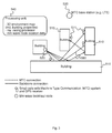
- Fig. 2 illustrates a block diagram of an embodiment of a communication system 500, which may correspond to the above communication system 400, with established information transmission of small cells 511, which may comprise the above transceiver apparatus 10, for further processing at an external processing unit 540, which comprises an embodiment of the above processing apparatus 20.
- Fig. 2 depicts a small cell backhaul system showing some buildings 510 with some small cells 511 distributed within the area. After powering up, the small cells 511 receive GPS signals and orientation information. Alternatively the location/orientation information may be entered manually if not equipped with GPS or orientation sensors and stored in a corresponding storage module.
- the small cells 511 comprise embodiments of the above described transceiver apparatuses 10.
- the small cells 511 use a machine-type communication system 570 or another low-frequency system to transmit the location and orientation information to a machine-type communication (MTC) or low-frequency node 530.
- MTC machine-type communication
- This node 530 is connected via a backbone 560 to the external processing unit 540.
- the small cell nodes 511 can also be connected directly to the backbone 560 and the external processing unit 540. This is indicated for the mm-wave backhaul node 520 and one of the small cells 511 in Fig. 2 .
- the external processing unit 540 contains a 3D map of the environment, a ray tracing processor implemented in the processing module 26, and the transmitted location information of the mm-wave nodes 511.
- the node location and orientation information may for example be stored also for further processing in e.g. a data base.
- the external processing unit 540 performs ray tracing simulations for the links between mm-wave backhaul node 520 and small cells 511.
- the direction of the strongest path represents the direction of the beam to be selected for backhaul connection.
- This directional information is then transmitted to the small cells 511 and to the backhaul node 520 via backbone 560 and MTC 570, via backbone 560 only, or via a low-frequency range communication system.
- multi-beam antenna pattern may be selected and appropriate beamforming weights may be applied. That is to say that in some embodiments the information related to the path direction may comprise information related to multiple paths between two transceivers, such that an according beam pattern may be adapted to the multiple paths.
- the processing module 16 may then determine multiple path directions or corresponding beamforming weights.
- beam pattern optimization may be carried out at a transceiver based on an initial beam pattern or path direction, for which weights may be provided as part of the information related to the path direction. Optimized beam weights or path information may then be used as part of the environmental data for improved future use.
- Fig. 3 illustrates a block diagram of an embodiment of a communication system with established mm-wave-link 580.
- the small cells 511 and backhaul nodes 520 steer their beams 580 in the right direction to establish the mm-wave link.
- the beams 580 may be reflected e.g. at a building 510.
- the reflections of the beam at buildings 510 have already been considered at the calculation of the beam directions at the processing unit 540.
- the apparatuses and methods described above provide a basic method for a realizable solution of fast mm-wave link establishment and beam tracking for flexible small cell backhaul or even access using mm-waves in scenarios with direct or reflected paths and high gain narrow beam antennas. It allows a dynamic mm-wave network management and optimization with high accuracy offline processing taking into account all network nodes.
- the apparatuses and methods described above may be faster than pure trial and error algorithms. They may provide flexibility for re-adjustment during operation of the system. Further, a network optimization and management of the mm-wave network over the same communication mechanism may be applicable. However, mm-wave operators may be free to either set up the offline processing for themselves or to offer it as a specifically tailored service also to other operators, or a third party may set up this service and offer it to operators.
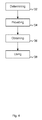
- Fig. 4 illustrates a block diagram of a flow chart of an embodiment of a method for a transceiver 100 of a communication system 400.
- the method comprises determining 32 information related to a position of a transceiver 100.
- the method further comprises providing 34 the information related to the position of the transceiver 100 to a processing device 20.
- the method comprises obtaining 36 information related to a path direction from the processing device 20.
- the method further comprises using 38 a directive antenna 30 to wirelessly communicate with another transceiver 300 being different from the processing device 20 based on the information related to the path direction.
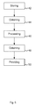
- Fig. 5 illustrates a block diagram of a flow chart of an embodiment of a method for a processing device 20 for determining information related to a path direction for a communication system 400.
- the method comprises storing 42 information related to environmental data of the communication system 400.
- the method further comprises obtaining 44 information related to a position of a transceiver device 10.
- the method comprises processing 46 the information related to the position of the transceiver device 10 based on the stored information related to the environmental data.
- the method further comprises obtaining 48 information related to a path direction.
- the method comprises providing 50 the information related to the path direction to the transceiver device 10.
- a further embodiment is a computer readable storage medium storing instructions which, when executed by a computer, cause the computer to implement one of the methods described herein.
- Other embodiments are a computer program or a computer program product having a program code for performing anyone of the above described methods, when the computer program or computer program product is executed on a processor, computer, or programmable hardware.
- program storage devices e.g., digital data storage media, which are machine or computer readable and encode machine-executable or computer-executable programs of instructions where said instructions perform some or all of the steps of methods described herein.
- the program storage devices may be, e.g., digital memories, magnetic storage media such as magnetic disks and magnetic tapes, hard drives, or optically readable digital data storage media.
- the embodiments are also intended to cover computers programmed to perform said steps of methods described herein or (field) programmable logic arrays ((F)PLAs) or (field) programmable gate arrays ((F)PGAs), programmed to perform said steps of the above-described methods.
- Functional blocks denoted as "means for " shall be understood as functional blocks comprising circuitry that is adapted for performing or to perform a certain function, respectively.
- a "means for s.th.” may as well be understood as a “means being adapted or suited for s.th.”.
- a means being adapted for performing a certain function does, hence, not imply that such means necessarily is performing said function (at a given time instant).
- any functional blocks labeled as “means”, “means for transceiving”, “means for storing”, “means for processing”, “means for locating”, etc. may be provided through the use of dedicated hardware, such as “a transceiver”, “a processor”, “a locator”, “a memory/storage”, etc. as well as hardware capable of executing software in association with appropriate software.
- any entity described herein as “means”, may correspond to or be implemented as “one or more modules", “one or more devices", “one or more units”, etc.
- the functions may be provided by a single dedicated processor, by a single shared processor, or by a plurality of individual processors, some of which may be shared.
- processor or “controller” should not be construed to refer exclusively to hardware capable of executing software, and may implicitly include, without limitation, digital signal processor (DSP) hardware, network processor, application specific integrated circuit (ASIC), field programmable gate array
- DSP digital signal processor
- ASIC application specific integrated circuit
- FPGA read only memory
- RAM random access memory
- non-volatile storage Other hardware, conventional or custom, may also be included. Their function may be carried out through the operation of program logic, through dedicated logic, through the interaction of program control and dedicated logic, or even manually, the particular technique being selectable by the implementer as more specifically understood from the context.
- any block diagrams herein represent conceptual views of illustrative circuitry embodying the principles of the invention.
- any flow charts, flow diagrams, state transition diagrams, pseudo code, and the like represent various processes which may be substantially represented in computer readable medium and so executed by a computer or processor, whether or not such computer or processor is explicitly shown.
- each claim may stand on its own as a separate embodiment. While each claim may stand on its own as a separate embodiment, it is to be noted that - although a dependent claim may refer in the claims to a specific combination with one or more other claims - other embodiments may also include a combination of the dependent claim with the subject matter of each other dependent claim. Such combinations are proposed herein unless it is stated that a specific combination is not intended. Furthermore, it is intended to include also features of a claim to any other independent claim even if this claim is not directly made dependent to the independent claim.
Landscapes
- Engineering & Computer Science (AREA)
- Computer Networks & Wireless Communication (AREA)
- Signal Processing (AREA)
- Physics & Mathematics (AREA)
- General Physics & Mathematics (AREA)
- Radar, Positioning & Navigation (AREA)
- Remote Sensing (AREA)
- Mobile Radio Communication Systems (AREA)
Abstract
Description
- Embodiments relate to apparatuses, methods and computer programs for determining information related to a path direction and for a transceiver of a communication device, more particularly but not exclusively, to radio frequency transmission in a millimeter-wavelength range.
- This section introduces aspects that may be helpful in facilitating a better understanding of the invention(s). Accordingly, the statements of this section are to be read in this light and are not to be understood as admissions about what is in the prior art or what is not in the prior art.
- Communication in higher frequency ranges than used by today's classical wireless systems, like 11-300GHz with so-called mm-Waves, may face the challenge to exploit Line-Of-Sight (LOS), Non LOS (NLOS), or reflected paths for e.g. small cell backhaul or access applications which may use high gain antennas with steerable beams to overcome the high pathloss. Due to the specific mm-wave propagation properties the channel may often consist only of one or two spatially separated paths, and a connection between a transmitter and a receiver may only be established when pointing a main lobe of an antenna pattern or beam of a high gain and narrow Half Power Beam Width (HPBW), for example using an antenna array, into the direction of the signal. However, the direction of the strongest path might not be known and a beam might not be steered initially into the right direction. At establishment of a mm-wave connection it may be considered difficult to derive the appropriate weights for the beam pattern from the highly attenuated signal to realize high gain pattern. The situation may be considered different from the situation at lower (e.g. 2.6 GHz) frequencies, where lower gains and less antenna elements would allow estimation of the beam pattern already from estimates of individual antenna elements.
- Some simplifications may be made in the following summary, which is intended to highlight and introduce some aspects of the various exemplary embodiments, but such simplifications are not intended to limit the scope of the inventions. Detailed descriptions of a preferred exemplary embodiment adequate to allow those of ordinary skill in the art to make and use the inventive concepts will follow in later sections.
- Various embodiments provide apparatuses, methods and computer programs for a processing apparatus for determining information related to a path direction and for a transceiver of a communication device. Embodiments may provide an efficient concept for locating initial beam directions for transmission and/or reception of one or more direct or reflected paths. Once a basic direction is found, tracking and optimization algorithms for beamforming, which then may operate with signals with sufficiently high SNR, may be applied. Hence, embodiments may enable or establish a fast method for finding an initial beam direction for reception or transmission along a direct or a reflected path. Embodiments may therefore reduce impairments due to poor propagation conditions, for example in high frequency communications such as using mm-Waves. Embodiments may enable more efficient communication in a communication system.
- Embodiments provide a processing apparatus for determining information related to a path direction for a communication system. The processing apparatus comprises a transceiver module, which is operable to obtain information related to a position of a transceiver device. Further, the processing apparatus comprises a storage module, which is operable to store information related to environmental data of the communication system. The processing apparatus further comprises a processing module, which is operable to process the information related to the position of the transceiver device based on the stored information related to the environmental data to obtain information related to a path direction. Further, the transceiver module is operable to provide the information related to the path direction to the transceiver device. Embodiments may enable efficient finding of initial beam directions for the transmission and/or reception of the direct or the reflected paths based on information in the environmental data, such as topology information and location information on static or semi-static transceivers of the communication system.
- In some embodiments the transceiver module may be operable to obtain information related to a position of another transceiver. The processing module may be operable to process the information related to the position of the transceiver device and the information related to the position of the other transceiver based on the stored information related to the environmental data to obtain information related to a path direction. In some embodiments, the processing module may be operable to obtain information on a path direction for the other transceiver as well. Embodiments may determine information related to path directions between two transceivers. In some embodiments information related to a location or position of one or more transceivers of the communication network, e.g. base station transceivers, may be comprised in the environmental data.
- In some embodiments the environmental data may comprise information related to a 3-dimensional representation of a coverage area of the communication system. Embodiments may enable accurate 3-dimensional prediction of the coverage area of the communication system.
- In further embodiments the transceiver module may be operable to communicate with the transceiver device according to a cellular wide area radio communication technology or according to a wired interface technology. Embodiments may enable the transceiver module to communicate with the transceiver device according to a cellular wide area radio communication technology or according to a wired interface technology before the information related to the path direction to the transceiver device is provided, such that the information related to the position of the transceiver device can be made available without directly using the communication system.
- In some embodiments the processing module may be operable to calculate, as information related to the path direction, at least one beam direction for a millimeter-wave radio communication based on 3-dimensional environmental data as information related to environmental data and Global Positioning System (GPS) location data as information related to the position of the transceiver device. Embodiments may make use of GPS location data of the transceiver device.
- In further embodiments the processing module may be operable to obtain the information related to the path direction based on a ray-tracing algorithm and the environmental data. Embodiments may enable determination of information related to the path direction using a ray-tracing model based on the environmental data of the communication system.
- In some embodiments the information related to the environmental data may comprise information related to reflections, reflection factors, information related to a position of one or more other transceivers and a topology of a coverage area of the communication system. Embodiments may enable accurate prediction of the actual path direction.
- In further embodiments the transceiver module may be operable to further receive information related to a radio link quality from the transceiver device. The processing module may be operable to update the environmental data and/or beam direction data based on the information related to the radio link quality. Embodiments may enable an updating mechanism of the environmental database related to the actual radio link quality. For example, after establishment of a radio link beam directions may be further improved using adaptive algorithms. Such beam or beam pattern improvement may lead to improvements in the radio link quality and hence such improved directional information may be used to update the environmental data. For example, shadowing effects may evoke changes in the radio quality of the coverage of the communication network when objects enter, leave, or move in the coverage area. Such changes could be monitored using information on an experienced radio link quality of the transceiver device and such information could be used to update or improve the environmental data. In other embodiments the environmental data may be replaced entirely or at least in part when the network topology changes, for example, when network components are at least partly installed, replaced, updated, or removed, etc.
- In some embodiments the processing module may be operable to statistically collect information related to radio communication in the communication system to update the environmental data and/or beam direction data. Embodiments may enable increased accuracy of the environmental data based on statistical information. For example, correction values may be stored for some locations based on which a beam direction or a path direction may be corrected afterwards for this location or for a set of locations of two transceivers.
- Embodiments further provide an apparatus for a transceiver of a communication system. The apparatus comprises a first transceiver module, which is operable to wirelessly communicate with another transceiver of the communication system. The first transceiver module is operable to use a directive antenna to communicate with the other transceiver. The apparatus further comprises a location module, which is operable to determine information related to a position of the apparatus. Further the apparatus comprises a second transceiver module. The second transceiver module is operable to communicate with a processing device, which is different from the other transceiver. Further, the second transceiver module is operable to provide the information related to the position of the apparatus to the processing device. The second transceiver module is further operable to obtain information related to a path direction from the processing device. The first transceiver module is further operable to use the directive antenna based on the information related to the path direction. The apparatus for a transceiver of a communication system may, for example, be comprised in or operable in a base station, a small cell, a user terminal etc. Embodiments may enable a transmitter and/or receiver, be it in a base station transceiver or in a mobile transceiver, for example the above transceiver device or the above other transceiver, respectively, to receive information on an initial beam or path direction from a processing device.
- In some embodiments, the first transceiver module of the transceiver apparatus may be operable to communicate in accordance with a millimeter-wave radio communication technology. Embodiments may enable to provide a higher data rate by using a millimeter-wave radio communication technology based on the information related to the path direction.
- In further embodiments the first transceiver module may be coupled to at least one antenna element adapted to the millimeter-wave radio communication technology. Alternatively, the first transceiver module may be coupled to a plurality of antenna elements adapted to the millimeter-wave radio communication technology. Embodiments may enable enhanced antenna gains in a millimeter-wave scenario.
- Additionally or alternatively the location module may comprise a Global Position System (GPS) receiver operable to determine a GPS-location of the apparatus as information related to the position of the apparatus. Embodiments may enable to determine the GPS location or position of the apparatus.
- Alternatively the location module may comprise a storage module for storing predetermined information related to the position of the apparatus. Embodiments may enable to use stored location data entered manually at installation or with another suitable method.
- In further embodiments, the second transceiver module of the apparatus may be operable to communicate with the processing device according to a cellular wide area radio communication technology. Embodiments may enable to communicate according to a cellular wide area radio communication technology, for example, to transfer initial information when a communication connection in accordance with the millimeter-wave radio communication technology is not yet available or disrupted.
- Alternatively the second transceiver module of the apparatus may be operable to communicate with the processing device according to a wired interface technology. Embodiments may enable to communicate according to a wired interface technology. Embodiments may save radio resources by using other communication technology such as wired communication for initial communication.
- Alternatively or additionally, the information related to the position of the apparatus may comprise information related to the location of the apparatus and information related to an orientation of the apparatus. Embodiments may enable to determine a more accurate path direction based on location information and on orientation information of the apparatus.
- In some embodiments, the location module may be operable to derive the information related to the orientation of the apparatus from received GPS data. In some embodiments the location module may contain an antenna and a receiver for several radio frequency signals received from several satellites of the satellite navigation system, an algorithm, which determines the location based on the received several radio frequency signals, and an output for information about the location. Embodiments may enable actual determination of the current location of the apparatus based on GPS location data.
- In some embodiments the orientation may for example be derived by an orientation measuring module containing for example a triaxial acceleration sensor, a triaxial gyroscope and a triaxial geomagnetic sensor, an algorithm, which determines the orientation based on a movement from a previous orientation to a current orientation, and an output for information about the orientation.
- In some embodiments the location module and the orientation measuring module may be implemented in terms of a computer program and a hardware component on which the computer program is executed, such as a DSP, an ASIC, an FPGA or any other processor.
- In some embodiments, the information related to the position of the apparatus may comprise information related to the height of the directive antenna. Embodiments may enable a more accurate determination of the path direction based on the height of the directive antenna.
- Alternatively or additionally the information related to the path direction may comprise information related to at least one beam direction for the directive antenna. Embodiments may enable faster adjustment of the directive antenna based on the current direction of the directive antenna.
- In further embodiments, a mobile transceiver or a base station transceiver or a small cell base station transceiver may comprise the above described apparatus.
- Embodiments further provide a method for a processing device for determining information related to a path direction for a communication system. The method comprises storing information related to environmental data of the communication system. The method further comprises obtaining information related to a position of a transceiver device. Further, the method comprises processing the information related to the position of the transceiver device based on the stored information related to the environmental data. The method further comprises obtaining information related to a path direction. Further, the method comprises providing the information related to the path direction to the transceiver device.
- Embodiments further provide a method for a transceiver of a communication system. The method comprises determining information related to a position of the transceiver. The method further comprises providing the information related to the position of the transceiver to a processing device. Further, the method comprises obtaining information related to a path direction from the processing device. The method further comprises using a directive antenna to wirelessly communicate with another transceiver being different from the processing device based on the information related to the path direction.
- Embodiments further provide a computer program having a program code for performing one or more of the above described methods, when the computer program is executed on a computer, processor, or programmable hardware component. A further embodiment is a computer readable storage medium storing instructions which, when executed by a computer, processor, or programmable hardware component, cause the computer to implement one of the methods described herein.
- Some other features or aspects will be described using the following non-limiting embodiments of apparatuses or methods or computer programs or computer program products by way of example only, and with reference to the accompanying figures, in which:
-
Fig. 1 illustrates a block diagram of an embodiment of an apparatus for determining information related to a path direction for a communication system and coupled to an embodiment of an apparatus for a transceiver of the communication system; -
Fig. 2 illustrates a block diagram of an embodiment of a communication system with established information transmission of small cells for further processing at an external processing unit; -
Fig. 3 illustrates a block diagram of an embodiment of a communication system with established mm-wave-links; -
Fig. 4 illustrates a block diagram of a flow chart of an embodiment of a method for a processing device for determining information related to a path direction for a communication system; and -
Fig. 5 illustrates a block diagram of a flow chart of an embodiment of a method for a transceiver of a communication system. - Various example embodiments will now be described more fully with reference to the accompanying drawings in which some example embodiments are illustrated. In the figures, the thicknesses of lines, layers or regions may be exaggerated for clarity.
- Accordingly, while example embodiments are capable of various modifications and alternative forms, embodiments thereof are shown by way of example in the figures and will herein be described in detail. It should be understood, however, that there is no intent to limit example embodiments to the particular forms disclosed, but on the contrary, example embodiments are to cover all modifications, equivalents, and alternatives falling within the scope of the invention. Like numbers refer to like or similar elements throughout the description of the figures.
- As used herein, the term, "or" refers to a non-exclusive or, unless otherwise indicated (e.g., "or else" or "or in the alternative"). Furthermore, as used herein, words used to describe a relationship between elements should be broadly construed to include a direct relationship or the presence of intervening elements unless otherwise indicated. For example, when an element is referred to as being "connected" or "coupled" to another element, the element may be directly connected or coupled to the other element or intervening elements may be present. In contrast, when an element is referred to as being "directly connected" or "directly coupled" to another element, there are no intervening elements present. Similarly, words such as "between", "adjacent", and the like should be interpreted in a like fashion.
- The terminology used herein is for the purpose of describing particular embodiments only and is not intended to be limiting of example embodiments. As used herein, the singular forms "a," "an" and "the" are intended to include the plural forms as well, unless the context clearly indicates otherwise. It will be further understood that the terms "comprises," "comprising," "includes" or "including," when used herein, specify the presence of stated features, integers, steps, operations, elements or components, but do not preclude the presence or addition of one or more other features, integers, steps, operations, elements, components or groups thereof.
- Unless otherwise defined, all terms (including technical and scientific terms) used herein have the same meaning as commonly understood by one of ordinary skill in the art to which example embodiments belong. It will be further understood that terms, e.g., those defined in commonly used dictionaries, should be interpreted as having a meaning that is consistent with their meaning in the context of the relevant art and will not be interpreted in an idealized or overly formal sense unless expressly so defined herein.
- In the following some embodiments of apparatuses, methods and computer programs for determining information related to a path direction for a communication system and for a transceiver of a communication device will be described. Initial beam directions for LOS or NLOS mm-wave connection may be evaluated when a link connection between mm-wave nodes, i.e. nodes in a communication network, e.g. small cells, is established.
- A straightforward concept may scan all spatial directions around a transmitter and a receiver location. A channel sounder may be used to investigate mm-wave NLOS channels and finding the correct direction may be difficult. Such difficulty may even be increased due to the fact that high gain antennas may be needed at transmitter and receiver to compensate for high pathloss with reasonable effort. Scanning all spatial directions may lead to relatively long trial and search phases, because for each direction at the transmitter all possible receiver directions may need to be scanned. Also there might not be an automatic protocol, so this method may be suitable for manually controlled channel investigations, but may be considered impossible to use for operation of a flexible and dynamic communication system.
- Other concepts may make use of iterative training or beam-searching algorithms. These methods may rely on iteratively testing of several candidate beams which are then gradually refined or narrowed. However, these algorithms suffer from a rather slow convergence time. Such algorithms may have a long convergence time which may often be unacceptable for mobile communications.
-
Fig. 1 illustrates a block diagram of an embodiment of aprocessing apparatus 20 for determining information related to a path direction for acommunication system 400. Information related to a path direction may comprise information on a direction of a propagation path, which may be one out of multiple propagation paths, or a direction of a signal path, etc. Theprocessing apparatus 20 may be implemented as one or more processing units, one or more processing devices, any means for processing, a computer, a server, one or more processors, programmable hardware, etc. Theprocessing apparatus 20 comprises atransceiver module 22 operable to obtain information related to a position of a transceiver device 10. It is to be noted that the information related to the position of thetransceiver device 20 may comprise information related to the position of one ormore antenna elements 30 of thetransceiver device 20. In some embodiments, for example for most mobile transceivers, the position of thedevice 20 and the position of itsantenna 30 may be relatively fixed, such that information on the position of thedevice 20 may allow determining the position of the one ormore antenna elements 30 or vice versa. In a similar manner, thetransceiver module 22 may be implemented as one or more transceiver devices, one or more transceiver units, any means for transceiving, i.e. receiving and/or transmitting etc. - A transceiver or
transceiver module 22 may be any means for transceiving, i.e. receiving and/or transmitting etc., and it may comprise typical receiver and transmitter components, such as one or more elements of the group of one or more Low-Noise Amplifiers (LNAs), one or more Power Amplifiers (PAs), one or more filters or filter circuitry, one or more diplexers, one or more duplexers, one or more Analog-to-Digital converters (A/D), one or more Digital-to-Analog converters (D/A), one or more modulators or demodulators, one or more mixers, one or more antennas, etc. - Further, the
processing apparatus 20 comprises astorage module 24 operable to store information related to environmental data of thecommunication system 400. Thestorage module 24 may be any kind of internal or external storage device or database, operable to store information. For example, thestorage module 26 may correspond to one or more memory or storage units, devices, any means for storing, such as, for example, a Read Only Memory (ROM), Random Access Memory (RAM), non-volatile storage, flash memory, a hard disk, solid state drive, etc. In addition, the storage module 24 (and also theprocessing module 26 which will be introduced subsequently) may also be used for additional mm-wave network (i.e. communication system 400) management tasks, e.g. to further optimize mm-wave operation through switching nodes on and off according to traffic requirements or resource management. Further, switching nodes on and off may increase the energy efficiency of the nodes. Thestorage module 24 may further be augmented or provided with feedback from the network nodes about the optimal beam directions after the termination of a beam refinement algorithm or after determination of stabilized beams for certain constellations of transceivers in thecommunication network 400. - The
processing apparatus 20 further comprises aprocessing module 26, which is coupled to thetransceiver module 22 and to thestorage module 24. Theprocessing module 26 is operable to process the information related to the position of the transceiver device 10 based on the stored information related to the environmental data to obtain information related to a path direction. In embodiments theprocessing module 26 may be implemented using one or more processing units, processing devices, any means for processing, such as a processor, a computer or a programmable hardware component being operable with accordingly adapted software. In other words, the above described functions of theprocessing module 26 may as well be implemented in software, which is then executed on one or more programmable hardware components. Such hardware components may comprise a general purpose processor, a Digital Signal Processor (DSP), a microcontroller, etc. Further, thetransceiver module 22 is operable to provide the information related to the path direction to the transceiver device 10. - It is to be noted that in embodiments path directions and also corresponding beam directions may be used to establish radio communication between two transceivers, e.g. a base station transceiver and a mobile transceiver, two mobile transceivers, two base station transceivers, etc. The environmental data may comprise information on the communication system, which may comprise location, position, and/or orientation information on one or more transceivers of the communication network, e.g. location and orientation of a base station transceiver. The
processing module 26 may then, for example, determine a path direction between a mobile transceiver, which provides its location information, and said base station transceiver for which location information is stored in the environmental data. - In some embodiments the
transceiver module 22 may be operable to obtain information related to a position of anothertransceiver 300, which is also indicated inFig.1 . For example, in such an embodiment, the transceiver device 10 and theother transceiver 300 may correspond to two mobile transceivers establishing a direct radio link between each other or also to two base station transceivers establishing a radio backhaul link between each other. Theprocessing module 26 may then be operable to process the information related to the position of the transceiver device 10 and the information related to the position of theother transceiver 300 based on the stored information related to the environmental data to obtain information related to a path direction. Accordingly, the information related to the path direction may then be provided to both the transceiver device 10 and theother transceiver 300. - The
processing apparatus 20, also herein referred to asexternal processing unit 20, may be a unit which is not necessarily part of thecommunication system 400, also herein referred to as mm-wave network 400. In other words the communication network may correspond to a network with a system carrier frequency of more than 2GHz, e.g. more than 5GHz, 7GHz, 10GHz, 20GHz, 50GHz, 70GHz, 100GHz, 200GHz, 300GHz, 500GHz, etc. Themobile communication system 400 may, for example, reuse protocols of or even correspond to one of the Third Generation Partnership Project (3GPP)-standardized mobile communication networks operable at or standardized for such a carrier frequency, where the term mobile communication system is used synonymously to mobile communication network. The mobile or wireless communication system may correspond to, for example, a 5G network, a Long-Term Evolution (LTE), an LTE-Advanced (LTE-A), High Speed Packet Access (HSPA), a Universal Mobile Telecommunication System (UMTS) or a UMTS Terrestrial Radio Access Network (UTRAN), an evolved-UTRAN (e-UTRAN), a Global System for Mobile communication (GSM) or Enhanced Data rates for GSM Evolution (EDGE) network, a GSM/EDGE Radio Access Network (GERAN), or mobile communication networks with different standards, for example, a Worldwide Inter-operability for Microwave Access (WIMAX) network IEEE 802.16 or Wireless Local Area Network (WLAN) IEEE 802.11, generally an Orthogonal Frequency Division Multiple Access (OFDMA) network, a Time Division Multiple Access (TDMA) network, a Code Division Multiple Access (CDMA) network, a Wideband-CDMA (WCDMA) network, a Frequency Division Multiple Access (FDMA) network, a Spatial Division Multiple Access (SDMA) network, etc. - In embodiments a
transceiver 100 may correspond to a base station transceiver, a mobile station transceiver, a relay station transceiver, a repeater, a small cell base station transceiver, etc. - A base station transceiver can be operable to communicate with one or more active mobile transceivers and a base station transceiver can be located in or adiacent to a coverage area of another base station transceiver, e.g. a macro cell base station transceiver or small cell base station transceiver. Hence, embodiments may provide a
mobile communication system 400 comprising one or more mobile transceivers and one or more base station transceivers, wherein the base station transceivers may establish macro cells or small cells, as e.g. pico-, metro-, or femto cells. A mobile transceiver may correspond to a smartphone, a cell phone, user equipment, a laptop, a notebook, a personal computer, a Personal Digital Assistant (PDA), a Universal Serial Bus (USB) -stick, a car, etc. A mobile transceiver may also be referred to as User Equipment (UE) or mobile in line with the 3GPP terminology. - A base station transceiver can be located in the fixed or stationary part of the network or system. A base station transceiver may correspond to a remote radio head, a transmission point, an access point, a macro cell, a small cell, a micro cell, a femto cell, a metro cell etc. A base station transceiver can be a wireless interface of a wired network, which enables transmission of radio signals to a UE or mobile transceiver. Such a radio signal may comply with radio signals as, for example, standardized by 3GPP or, generally, in line with one or more of the above listed systems. Thus, a base station transceiver may correspond to a NodeB, an eNodeB, a Base Transceiver Station (BTS), an access point, a remote radio head, a transmission point etc., which may be further subdivided in a remote unit and a central unit.
- A mobile transceiver can be associated, camped on, or registered with a base station transceiver or cell. The term cell refers to a coverage area of radio services provided by a base station transceiver, e.g. a NodeB (NB), an eNodeB (eNB), a remote radio head, a transmission point, etc. A base station transceiver may operate one or more cells on one or more frequency layers, in some embodiments a cell may correspond to a sector. For example, sectors can be achieved using sector antennas, which provide a characteristic for covering an angular section around a remote unit or base station transceiver. In some embodiments, a base station transceiver may, for example, operate three or six cells covering sectors of 120° (in case of three cells), 60° (in case of six cells) respectively. A base station transceiver may operate multiple sectorized antennas. In the following a cell may represent an according base station transceiver generating the cell or, likewise, a base station transceiver may represent a cell the base station transceiver generates.
- In other words, in embodiments the
mobile communication system 400 may correspond to a HetNet, which utilizes different cell types, i.e. Closed Subscriber Group (CSG) cells and open cells, and cells of different sizes, as, for example, macro cells and small cells, where the coverage area of a small cell is smaller than the coverage area of a macro cell. A small cell may correspond to a metro cell, a micro cell, a pico cell, a femto cell, etc. Such cells are established by base station transceivers for which their coverage areas are determined by their transmission power and interference condition. In some embodiments a small cell's coverage area can at least partly be surrounded by the coverage area of a macro cell established by another base station transceiver. The small cells can be deployed to extend the capacity of the network. A metro cell may therefore be used to cover a smaller area than a macro cell, e.g. a metro cell may cover a street or a section in a metropolitan area. For a macro cell the coverage area may have a diameter in the order of one or more kilometers, for a micro cell the coverage area may have a diameter below a kilometer, and for a pico cell the coverage area may have a diameter below a 100m. A femto cell may be the smallest cell and it may be used to cover a household or gate section at the airport, i.e. its coverage area may have a diameter below 50m. Thus, a base station transceiver may also be referred to as cell. - In some embodiments, the environmental data comprises information related to a 3-dimensional representation of a coverage area of the
communication system 400. In other words, the environmental data may comprise 3-dimensional topology data of the coverage area of thecommunication network 400, which may comprise, base station transceiver locations, obstacles, buildings, cell structures, etc. In embodiments, theprocessing apparatus 20 may be connected via a backbone connection to thecommunication system 400. A backbone may be a communication link with a high bandwidth for transmission of large amounts of data. Theprocessing apparatus 20 may receive location information, for example about the GPS location information, of one or more mm-wave nodes in thecommunication system 400. - In further embodiments the
transceiver module 22 may be operable to communicate with the transceiver device 10 according to a cellular wide area radio communication technology or according to a wired interface technology. The communication with theexternal processing apparatus 20 may for example be done over (existing) secondary communication systems at lower frequencies. A low frequency communication system and/or external data base stations transceivers and mobile transceivers could be operated by the mm-wave system provider or could also be applied as third party service. For example, such a cellular wide area network may correspond to or comply with one of the above listed standards and it may be operable at respective lower frequencies. In other embodiments such communication may be carried out using wired communication, e.g. twisted pair, Ethernet, T1, optical data transmission, etc. - In some embodiments the
processing module 26 may be operable to calculate, as information related to the path direction, at least one beam direction for a millimeter-wave radio communication based on 3-Dimensional (3D) environmental data as information related to environmental data and Global Positioning System (GPS) location data as information related to the position of the transceiver device 10. A beam direction may correspond to a direction of a main lobe of an antenna pattern which may be formed at a transceiver using a directive antenna. - As has been mentioned above, embodiments may use beamforming to implement a directive antenna, which is to be understood as signal processing means to achieve defined or controlled superposition of the signals transmitted by the individual transmit/receive antenna elements. For example, a geometry of a plurality of transmit/receive antenna elements may correspond to a linear antenna array, a circular antenna array, , any two-dimensional antenna array or field, or even an arbitrary antenna array, for as long as geometrical relations between the antenna elements are known or controlled. In some embodiments, a plurality of antenna elements or transmit/receive antennas may correspond to a uniform linear antenna array, wherein the transmit/receive antennas are spaced uniformly, and wherein the distance between two antenna elements may correspond to, for example, half of a wavelength of the carrier frequency of the signals transmitted/received using these antennas. As known for beamforming, by providing phase shifted versions of the same signal to different antenna elements, constructive and destructive superposition of the transmitted/received signals may be achieved for different angular directions with respect to these antennas. The more antennas are used, the higher the overall BF gain and the narrower a beam that may be formed. In embodiments a transmit/receive antenna or a transmit/receive antenna element may use an individual beam pattern covering a sector or a cell of the base station transceiver, e.g. a 90° half power beam width antenna pattern to cover a 120° sector or cell.
- In further embodiments the
processing module 26 may be operable to obtain the information related to the path direction based on a ray-tracing algorithm and the environmental data. Ray tracing may be a reliable method to predict angles of departure and angles of arrival. Theexternal processing apparatus 20 may contain a 3D environmental database, a ray tracing program and may also store the transmitted location data of the network nodes. In some embodiments the environmental data may comprise information related to a 3-D representation of a coverage area of the communication system. Based on this information, theexternal processing apparatus 20 may calculate beam directions needed to connect mm-wave nodes, e.g. backhaul nodes and small cells, or mm-wave access points and mm-wave UEs. - In some embodiments the information related to the environmental data may comprise information related to reflections, reflection factors, information related to a position of one or more
other transceivers 300 and a topology of a coverage area of thecommunication system 400. With knowledge of reflections, reflection factors, information related to a position of one or moreother transceivers 300 and a topology of a coverage area of the communication system 400 a highly accurate beam direction may be provided to the nodes of thecommunication system 400. - In further embodiments the
transceiver module 22 may be operable to further receive information related to a radio link quality from the transceiver device 10. Theprocessing module 26 may be operable to update the environmental data and/or beam direction data based on the information related to the radio link quality. For example, changes in the radio coverage may be determined or detected and corresponding updating measures on the environmental data may be taken, e.g. by means of correction values or update of the entire environmental data. In other words, transceivers operable in thecommunication network 400 may collect information on their respective radio links within thenetwork 400. In some embodiments, such information may be used to update the environmental data and/or beam direction data and improve the determination of the information related to the path direction. - In some embodiments the
processing module 26 may be operable to statistically collect information related to radio communication in thecommunication system 400 to update the environmental data and/or beam direction data. In other words, the accuracy of the environmental data may be increased based on further statistical information. Likewise, transceivers or transceiver devices 10 may as well be operable to provide statistical information to the above describedprocessing device 20 to allow for statistical improvement of the environmental data. -
Fig. 1 further illustrates a block diagram of an embodiment of an apparatus 10 for atransceiver 100 of acommunication system 400. In other words, the apparatus 10 may be adapted to or operable in atransceiver 100; may be operated by or comprised in thetransceiver 100. Embodiments may also provide a transceiver 100 (dashed lines inFig. 1 ) comprising the apparatus 10. The apparatus 10 comprises a first transceiver module 12. The transceiver module 12 may correspond to asimilar transceiver module 22 as described above, however, adapted to abase station transceiver 100, mobile transceiver, a relay station transceiver, a repeater, etc., comprising the above described typical transceiver components. In a similar manner, the transceiver module 12 may be implemented as one or more transceiver devices, one or more transceiver units, any means for transceiving, i.e. receiving and/or transmitting, etc. - The first transceiver module 12 is operable to wirelessly communicate with another
transceiver 300 of thecommunication system 400. The first transceiver module 12 is operable to use adirective antenna 30 to communicate with theother transceiver 300. Thetransceiver 100 may correspond to a base station transceiver, e.g. a small cell transceiver, or a mobile transceiver and hence, theother transceiver 300 may correspond to a respective mobile transceiver or a small cell transceiver or a base station transceiver. - The
directive antenna 30 may, for example, be a rectangular planar antenna array which contains 36 antenna elements in a 6 x 6 arrangement. An antenna array with such a large number of antenna elements may be also called a massive Multiple-Input-Multiple-Output (MIMO) antenna array. Alternatively, the rectangular planar antenna array may contain for example 25 antenna elements in a 5 x 5 arrangement, 40 antenna elements in a 8 x 5 arrangement (8 columns and 5 rows), 50 antenna elements in a 5 x 10 arrangement (5 columns and 10 rows) or 64 antenna elements in a 8 x 8 arrangement. Certainly, rectangular planar antenna arrays with further number of antenna elements in further arrangements of columns and rows may be used for the directive antenna, or likewise any of the above-described antenna arrangements for beamforming. - The apparatus 10 further comprises a
location module 14. Thelocation module 14 is operable to determine information related to a position of the apparatus 10. Thelocation module 14 may be implemented as one or more location units, one or more location devices, any mean for locating, etc. Thelocation module 14 may determine the information related to the position of the apparatus 10 by receiving time shifted signals, for example, from satellites, using triangulation, or any means for locating. For example, thelocation module 14 may comprise a receiver of a global or regional navigation satellite system such as GPS, GLobalnaya NAvigatsionnaya Sputnikovaya Sistema (GLONASS, Russian global navigation satellite system), Galileo (global navigation satellite system currently being built by the European Union (EU) and European Space Agency (ESA)), Indian Regional Navigation Satellite System (IRNSS) being developed by the Indian Space Research Organization (ISRO)) or Beidou-2 (a Chinese satellite navigation system). - Further, the apparatus 10 comprises a
second transceiver module 16, which is coupled to the first transceiver module 12 and to thelocation module 14. Thesecond transceiver module 16 may correspond to asimilar transceiver module 22 as described above; however, adapted to a base station transceiver or amobile transceiver 100, comprising the above described typical transceiver components. In a similar manner, thetransceiver module 16 may be implemented as one or more transceiver devices, one or more transceiver units, any means for transceiving, i.e. receiving and/or transmitting, etc. - The
second transceiver module 16 is operable to communicate with theprocessing device 20 being different from theother transceiver 300. In other words, the processing device may correspond to an entity which is different from theother transceiver 300. Further, thesecond transceiver module 16 is operable to provide the information related to the position of the apparatus 10 to theprocessing device 20. - The
second transceiver module 16 is further operable to obtain the information related to the path direction from theprocessing device 20. For example, the transceivers/nodes may receive the beam direction information, for example using an LTE machine-type communication network according to 3GPP Rel. 11, from theprocessing device 20. - The first transceiver module 12 is further operable to use the
directive antenna 30 based on the information related to the path direction. Based on the received information the transceiver ortransceiver node 100 may start setting up a mm-wave connection with already almost accurate beam directions. Further optimization may then take place on the PHYsical (PHY) layer of the mm-wave system. This information may be used to enhance the stored beam directions in the environmental data for a specific connection for future use (location dependent). - In some embodiments the first transceiver module 12 may be operable to communicate in accordance with a millimeter-wave radio communication technology in line with the above description. In some embodiments the first transceiver module 12 may be coupled to at least one antenna element adapted to the millimeter-wave radio communication technology, also in line with the above beamforming description and the corresponding antenna elements and arrangements.
- The first transceiver module 12 may be operable to communicate according to a millimeter-wave radio communication technology, wherein the
second transceiver module 16 may be operable to communicate according to a cellular wide area radio communication technology or according to a wired interface technology, as has been explained above with respect to theprocessing unit 20. - Additionally or alternatively the
location module 14 may comprise a Global Position System (GPS) receiver, or any other navigation system receiver as mentioned above, which is operable to receive a location data (e.g. GPS-location) of the apparatus 10 as information related to the position of the apparatus 10. The mm-wave network nodes (base stations, small cells, or user terminals) may be equipped with a navigation system/GPS receiver and may collect (GPS) location information (e.g. including height). In some embodiments also the orientation of the node (e.g. direction of boresight of antenna array) may be derived by help of GPS functionality, orientation sensors, or may be entered (coded) manually at installation (for fixed nodes) or with another suitable method. - Alternatively the
location module 14 may for example be a receiver of a global or regional navigation satellite system such as GLONASS Galileo, IRNSS or Beidou-2. - In some embodiments the
location module 14 may comprise a storage module for storing predetermined information related to the position of the apparatus 10. The storage may for example be an internal or external database operable to store information related to the position of the apparatus 10 and further information, for example on a hard drive. - For communication according to the cellular wide area radio communication technology the
second transceiver module 16 may use a further antenna. The further antenna may be an antenna with a single antenna element or also a MIMO/beamforming antenna array with for example 4 antenna elements in a 2 x 2 arrangement. - Additionally or alternatively, the information related to the position of the apparatus 10 may comprise information related to the location of the apparatus 10 and information related to an orientation of the apparatus 10. The location information is transmitted to the
external processing unit 20. The mm-wave link may not be established yet or may be disrupted and the transmission of the location information is done, for example, with an existing LTE Machine-type communication network as e.g. according to 3GPP Rel. 11. - In some embodiments the information related to the position of the apparatus 10 may comprise information related to the height of the
directive antenna 30. Additionally or alternatively, the information related to the path direction comprises information related to at least one beam direction for thedirective antenna 30. - In some embodiments mobile transceivers may download a map from the
external data base 20 which contains the optimal beam directions for every given position in a certain area. Thus, the communication cycle or the frequency of communication with theexternal server 20 could be reduced. In such an embodiment the information related to the position of the transceiver device 10 (e.g. the mobile transceiver) may correspond to information related to the area the mobile transceiver 10 is located in. The information related to the path direction as provided in return from theprocessing apparatus 20 may then be comprised in map data, i.e. in a collection of data indicating path directions for multiple positions. -
Fig. 2 illustrates a block diagram of an embodiment of acommunication system 500, which may correspond to theabove communication system 400, with established information transmission ofsmall cells 511, which may comprise the above transceiver apparatus 10, for further processing at anexternal processing unit 540, which comprises an embodiment of theabove processing apparatus 20.Fig. 2 depicts a small cell backhaul system showing somebuildings 510 with somesmall cells 511 distributed within the area. After powering up, thesmall cells 511 receive GPS signals and orientation information. Alternatively the location/orientation information may be entered manually if not equipped with GPS or orientation sensors and stored in a corresponding storage module. Thesmall cells 511 comprise embodiments of the above described transceiver apparatuses 10. In the present embodiment thesmall cells 511 use a machine-type communication system 570 or another low-frequency system to transmit the location and orientation information to a machine-type communication (MTC) or low-frequency node 530. Thisnode 530 is connected via abackbone 560 to theexternal processing unit 540. - Alternatively, if appropriate interfaces are available near the
small cell nodes 511, they can also be connected directly to thebackbone 560 and theexternal processing unit 540. This is indicated for the mm-wave backhaul node 520 and one of thesmall cells 511 inFig. 2 . - The
external processing unit 540 contains a 3D map of the environment, a ray tracing processor implemented in theprocessing module 26, and the transmitted location information of the mm-wave nodes 511. The node location and orientation information may for example be stored also for further processing in e.g. a data base. - The
external processing unit 540 performs ray tracing simulations for the links between mm-wave backhaul node 520 andsmall cells 511. The direction of the strongest path represents the direction of the beam to be selected for backhaul connection. This directional information is then transmitted to thesmall cells 511 and to thebackhaul node 520 viabackbone 560 andMTC 570, viabackbone 560 only, or via a low-frequency range communication system. - Alternatively, if multiple strong paths are present, also multi-beam antenna pattern may be selected and appropriate beamforming weights may be applied. That is to say that in some embodiments the information related to the path direction may comprise information related to multiple paths between two transceivers, such that an according beam pattern may be adapted to the multiple paths. The
processing module 16 may then determine multiple path directions or corresponding beamforming weights. In other embodiments beam pattern optimization may be carried out at a transceiver based on an initial beam pattern or path direction, for which weights may be provided as part of the information related to the path direction. Optimized beam weights or path information may then be used as part of the environmental data for improved future use. -
Fig. 3 illustrates a block diagram of an embodiment of a communication system with established mm-wave-link 580. With the directional information received from thebackhaul node 520 viabackbone 560 andMTC 570, viabackbone 560 only, or via a low-frequency range communication system (Fig. 2 ), thesmall cells 511 andbackhaul nodes 520 steer theirbeams 580 in the right direction to establish the mm-wave link. Thebeams 580 may be reflected e.g. at abuilding 510. The reflections of the beam atbuildings 510 have already been considered at the calculation of the beam directions at theprocessing unit 540. - The apparatuses and methods described above provide a basic method for a realizable solution of fast mm-wave link establishment and beam tracking for flexible small cell backhaul or even access using mm-waves in scenarios with direct or reflected paths and high gain narrow beam antennas. It allows a dynamic mm-wave network management and optimization with high accuracy offline processing taking into account all network nodes.
- The apparatuses and methods described above may be faster than pure trial and error algorithms. They may provide flexibility for re-adjustment during operation of the system. Further, a network optimization and management of the mm-wave network over the same communication mechanism may be applicable. However, mm-wave operators may be free to either set up the offline processing for themselves or to offer it as a specifically tailored service also to other operators, or a third party may set up this service and offer it to operators.
-
Fig. 4 illustrates a block diagram of a flow chart of an embodiment of a method for atransceiver 100 of acommunication system 400. The method comprises determining 32 information related to a position of atransceiver 100. The method further comprises providing 34 the information related to the position of thetransceiver 100 to aprocessing device 20. Further, the method comprises obtaining 36 information related to a path direction from theprocessing device 20. The method further comprises using 38 adirective antenna 30 to wirelessly communicate with anothertransceiver 300 being different from theprocessing device 20 based on the information related to the path direction. -
Fig. 5 illustrates a block diagram of a flow chart of an embodiment of a method for aprocessing device 20 for determining information related to a path direction for acommunication system 400. The method comprises storing 42 information related to environmental data of thecommunication system 400. The method further comprises obtaining 44 information related to a position of a transceiver device 10. Further, the method comprises processing 46 the information related to the position of the transceiver device 10 based on the stored information related to the environmental data. The method further comprises obtaining 48 information related to a path direction. Further, the method comprises providing 50 the information related to the path direction to the transceiver device 10. - A further embodiment is a computer readable storage medium storing instructions which, when executed by a computer, cause the computer to implement one of the methods described herein. Other embodiments are a computer program or a computer program product having a program code for performing anyone of the above described methods, when the computer program or computer program product is executed on a processor, computer, or programmable hardware.
- A person of skill in the art would readily recognize that steps of various above-described methods can be performed by programmed computers. Herein, some embodiments are also intended to cover program storage devices, e.g., digital data storage media, which are machine or computer readable and encode machine-executable or computer-executable programs of instructions where said instructions perform some or all of the steps of methods described herein. The program storage devices may be, e.g., digital memories, magnetic storage media such as magnetic disks and magnetic tapes, hard drives, or optically readable digital data storage media. The embodiments are also intended to cover computers programmed to perform said steps of methods described herein or (field) programmable logic arrays ((F)PLAs) or (field) programmable gate arrays ((F)PGAs), programmed to perform said steps of the above-described methods.
- The description and drawings merely illustrate the principles of the invention. It will thus be appreciated that those skilled in the art will be able to devise various arrangements that, although not explicitly described or shown herein, embody the principles of the invention and are included within its spirit and scope. Furthermore, all examples recited herein are principally intended expressly to be only for pedagogical purposes to aid the reader in understanding the principles of the invention and the concepts contributed by the inventor(s) to furthering the art, and are to be construed as being without limitation to such specifically recited examples and conditions. Moreover, all statements herein reciting principles, aspects, and embodiments of the invention, as well as specific examples thereof, are intended to encompass equivalents thereof.
- Functional blocks denoted as "means for ..." (performing a certain function) shall be understood as functional blocks comprising circuitry that is adapted for performing or to perform a certain function, respectively. Hence, a "means for s.th." may as well be understood as a "means being adapted or suited for s.th.". A means being adapted for performing a certain function does, hence, not imply that such means necessarily is performing said function (at a given time instant).
- The functions of the various elements shown in the Figures, including any functional blocks labeled as "means", "means for transceiving", "means for storing", "means for processing", "means for locating", etc., may be provided through the use of dedicated hardware, such as "a transceiver", "a processor", "a locator", "a memory/storage", etc. as well as hardware capable of executing software in association with appropriate software. Moreover, any entity described herein as "means", may correspond to or be implemented as "one or more modules", "one or more devices", "one or more units", etc. When provided by a processor, the functions may be provided by a single dedicated processor, by a single shared processor, or by a plurality of individual processors, some of which may be shared. Moreover, explicit use of the term "processor" or "controller" should not be construed to refer exclusively to hardware capable of executing software, and may implicitly include, without limitation, digital signal processor (DSP) hardware, network processor, application specific integrated circuit (ASIC), field programmable gate array
- (FPGA), read only memory (ROM) for storing software, random access memory (RAM), and non-volatile storage. Other hardware, conventional or custom, may also be included. Their function may be carried out through the operation of program logic, through dedicated logic, through the interaction of program control and dedicated logic, or even manually, the particular technique being selectable by the implementer as more specifically understood from the context.
- It should be appreciated by those skilled in the art that any block diagrams herein represent conceptual views of illustrative circuitry embodying the principles of the invention. Similarly, it will be appreciated that any flow charts, flow diagrams, state transition diagrams, pseudo code, and the like represent various processes which may be substantially represented in computer readable medium and so executed by a computer or processor, whether or not such computer or processor is explicitly shown.
- Furthermore, the following claims are hereby incorporated into the Detailed Description, where each claim may stand on its own as a separate embodiment. While each claim may stand on its own as a separate embodiment, it is to be noted that - although a dependent claim may refer in the claims to a specific combination with one or more other claims - other embodiments may also include a combination of the dependent claim with the subject matter of each other dependent claim. Such combinations are proposed herein unless it is stated that a specific combination is not intended. Furthermore, it is intended to include also features of a claim to any other independent claim even if this claim is not directly made dependent to the independent claim.
- It is further to be noted that methods disclosed in the specification or in the claims may be implemented by a device having means for performing each of the respective steps of these methods.
Claims (15)
- A processing apparatus (20) for determining information related to a path direction for a communication system (400), comprising
a transceiver module (22) operable to obtain information related to a position of a transceiver device (10);
a storage module (24) operable to store information related to environmental data of the communication system (400); and
a processing module (26) operable to process the information related to the position of the transceiver device (10) based on the stored information related to the environmental data to obtain information related to a path direction,
wherein the transceiver module (22) is operable to provide the information related to the path direction to the transceiver device (10). - The apparatus (20) of claim 1, wherein the transceiver module (22) is operable to obtain information related to a position of another transceiver (300), and wherein the processing module (26) is operable to process the information related to the position of the transceiver device (10) and the information related to the position of the other transceiver (300) based on the stored information related to the environmental data to obtain information related to a path direction.
- The apparatus (20) of claim 1, wherein the transceiver module (22) is operable to communicate with the transceiver device (10) according to a cellular wide area radio communication technology or according to a wired interface technology.
- The apparatus (20) of claim 1, wherein the processing module (26) is operable to calculate, as information related to the path direction, at least one beam direction for a millimeter-wave radio communication based on 3-dimensional environmental data as information related to environmental data and Global Positioning System (GPS) location data as information related to the position of the transceiver device (10).
- The apparatus (20) of claim 1, wherein the environmental data comprises information related to a 3-dimensional representation of a coverage area of the communication system (400), and/or wherein the processing module (26) is operable to obtain the information related to the path direction based on a ray-tracing algorithm and the environmental data.
- The apparatus (20) of claim 1, wherein the information related to the environmental data comprises information related to reflections, reflection factors, information related to a position of one or more other transceivers (300), and a topology of a coverage area of the communication system (400).
- The apparatus (20) of claim 1, wherein the transceiver module (22) is operable to further receive information related to a radio link quality from the transceiver device (10), and wherein processing module (26) is operable to update the environmental data and/or beam direction data based on the information related to the radio link quality.
- The apparatus (20) of claim 1, wherein the processing module (26) is operable to statistically collect information related to radio communication in the communication system (400) to update the environmental data and/or beam direction data.
- An apparatus (10) for a transceiver (100) of a communication system (400), comprising:a first transceiver module (12) operable to wirelessly communicate with another transceiver (300) of the communication system (400), the first transceiver module (12) being operable to use a directive antenna (30) to communicate with the other transceiver (300);a location module (14) operable to determine information related to a position of the apparatus (10); anda second transceiver module (16) operable to:communicate with a processing device (20) being different from the other transceiver (300),provide the information related to the position of the apparatus (10) to the processing device (20), andobtain information related to a path direction from the processing device (20);wherein the first transceiver module (12) is further operable to use the directive antenna (30) based on the information related to the path direction.
- The apparatus (10) of claim 9, wherein the first transceiver module (12) is operable communicate in accordance with a millimeter-wave radio communication technology and wherein the first transceiver module (12) is coupled to at least one antenna element adapted to the millimeter-wave radio communication technology, and/or wherein the location module (14) comprises a Global Position System (GPS) receiver operable to determine a GPS-location of the apparatus (10) as information related to the position of the apparatus (10), or wherein the location module (14) comprises a storage module for storing predetermined information related to the position of the apparatus (10).
- The apparatus (10) of claim 9, wherein the second transceiver module (16) is operable to communicate with the processing device (20) according to a cellular wide area radio communication technology or according to a wired interface technology, and/or wherein the information related to the position of the apparatus (10) comprises information related to the location of the apparatus (10) and information related to an orientation of the apparatus (10).
- The apparatus (10) of claim 9, wherein the information related to the position of the apparatus (10) comprises information related to the height of the directive antenna (30), and/or wherein the information related to the path direction comprises information related to at least one beam direction for the directive antenna (30).
- A method for a processing device (20) for determining information related to a path direction for a communication system (400), comprising
storing (42) information related to environmental data of the communication system (400);
obtaining (44) information related to a position of a transceiver device (10);
and
processing (46) the information related to the position of the transceiver device (10) based on the stored information related to the environmental data;
obtaining (48) information related to a path direction;
providing (50) the information related to the path direction to the transceiver device (10). - A method for a transceiver (100) of a communication system (400), comprising
determining (32) information related to a position of the transceiver (100);
providing (34) the information related to the position of the transceiver (100) to a processing device (20);
obtaining (36) information related to a path direction from the processing device (20); and
using (38) a directive antenna (30) to wirelessly communicate with another transceiver (300) being different from the processing device (20) based on the information related to the path direction. - A computer program having a program code for performing at least one of the methods of claims 13 or 14, when the computer program is executed on a computer, a processor, or a programmable hardware component
Priority Applications (1)
| Application Number | Priority Date | Filing Date | Title |
|---|---|---|---|
| EP14305250.4A EP2911435B1 (en) | 2014-02-24 | 2014-02-24 | Apparatuses, methods and computer programs for determining information related to a path direction and for a transceiver of a communication device |
Applications Claiming Priority (1)
| Application Number | Priority Date | Filing Date | Title |
|---|---|---|---|
| EP14305250.4A EP2911435B1 (en) | 2014-02-24 | 2014-02-24 | Apparatuses, methods and computer programs for determining information related to a path direction and for a transceiver of a communication device |
Publications (2)
| Publication Number | Publication Date |
|---|---|
| EP2911435A1 true EP2911435A1 (en) | 2015-08-26 |
| EP2911435B1 EP2911435B1 (en) | 2020-02-12 |
Family
ID=50473223
Family Applications (1)
| Application Number | Title | Priority Date | Filing Date |
|---|---|---|---|
| EP14305250.4A Active EP2911435B1 (en) | 2014-02-24 | 2014-02-24 | Apparatuses, methods and computer programs for determining information related to a path direction and for a transceiver of a communication device |
Country Status (1)
| Country | Link |
|---|---|
| EP (1) | EP2911435B1 (en) |
Cited By (5)
| Publication number | Priority date | Publication date | Assignee | Title |
|---|---|---|---|---|
| CN105682110A (en) * | 2016-01-22 | 2016-06-15 | 工业和信息化部电信研究院 | Method and device of determining a serving high frequency micro base station for user equipment |
| JP2018537057A (en) * | 2015-11-17 | 2018-12-13 | ホアウェイ・テクノロジーズ・カンパニー・リミテッド | System and method for multi-source channel estimation |
| WO2019053079A1 (en) * | 2017-09-14 | 2019-03-21 | Fraunhofer-Gesellschaft zur Förderung der angewandten Forschung e.V. | Transceiver with a sensor for calculating positional information of an antenna of a further transceiver |
| US10638479B2 (en) | 2015-11-17 | 2020-04-28 | Futurewei Technologies, Inc. | System and method for multi-source channel estimation |
| US20200252148A1 (en) * | 2018-03-27 | 2020-08-06 | Fundacion Imdea Networks | Method for determining geometric information of devices in millimeter-wave networks |
Citations (6)
| Publication number | Priority date | Publication date | Assignee | Title |
|---|---|---|---|---|
| US7996034B1 (en) * | 2005-01-28 | 2011-08-09 | National Semiconductor Corporation | Cellular telephone handset with increased reception sensitivity and reduced transmit power levels |
| US20110287778A1 (en) * | 2010-05-24 | 2011-11-24 | Moshe Levin | Method and system for estimation of mobile station velocity in a cellular system based on geographical data |
| EP2405687A1 (en) * | 2009-03-04 | 2012-01-11 | Sony Corporation | Communication apparatus, communication method, computer program, and communication system |
| US20120119953A1 (en) * | 2008-11-04 | 2012-05-17 | Kenichi Hosoya | Control method of wireless communication system, wireless communication system, adjustment method of array weight vector, and wireless communication device |
| WO2012120444A1 (en) * | 2011-03-07 | 2012-09-13 | Sisvel Technology S.R.L. | Multi-antenna transmission process and system and relative mobile terminal |
| WO2013089731A1 (en) * | 2011-12-15 | 2013-06-20 | Intel Corporation | Use of location information in multi-radio devices for mmwave beamforming |
Family Cites Families (3)
| Publication number | Priority date | Publication date | Assignee | Title |
|---|---|---|---|---|
| JP4332738B2 (en) * | 2005-03-31 | 2009-09-16 | ソニー株式会社 | Data communication apparatus, data communication method, and data communication packet |
| US8284748B2 (en) * | 2010-07-07 | 2012-10-09 | Apple Inc. | Ad hoc formation and tracking of location-sharing groups |
| CN104185269B (en) * | 2013-05-22 | 2019-03-12 | 中兴通讯股份有限公司 | A kind of method for building up and terminal device of millimeter wave wireless communication link |
-
2014
- 2014-02-24 EP EP14305250.4A patent/EP2911435B1/en active Active
Patent Citations (6)
| Publication number | Priority date | Publication date | Assignee | Title |
|---|---|---|---|---|
| US7996034B1 (en) * | 2005-01-28 | 2011-08-09 | National Semiconductor Corporation | Cellular telephone handset with increased reception sensitivity and reduced transmit power levels |
| US20120119953A1 (en) * | 2008-11-04 | 2012-05-17 | Kenichi Hosoya | Control method of wireless communication system, wireless communication system, adjustment method of array weight vector, and wireless communication device |
| EP2405687A1 (en) * | 2009-03-04 | 2012-01-11 | Sony Corporation | Communication apparatus, communication method, computer program, and communication system |
| US20110287778A1 (en) * | 2010-05-24 | 2011-11-24 | Moshe Levin | Method and system for estimation of mobile station velocity in a cellular system based on geographical data |
| WO2012120444A1 (en) * | 2011-03-07 | 2012-09-13 | Sisvel Technology S.R.L. | Multi-antenna transmission process and system and relative mobile terminal |
| WO2013089731A1 (en) * | 2011-12-15 | 2013-06-20 | Intel Corporation | Use of location information in multi-radio devices for mmwave beamforming |
Cited By (7)
| Publication number | Priority date | Publication date | Assignee | Title |
|---|---|---|---|---|
| JP2018537057A (en) * | 2015-11-17 | 2018-12-13 | ホアウェイ・テクノロジーズ・カンパニー・リミテッド | System and method for multi-source channel estimation |
| US10638479B2 (en) | 2015-11-17 | 2020-04-28 | Futurewei Technologies, Inc. | System and method for multi-source channel estimation |
| CN105682110A (en) * | 2016-01-22 | 2016-06-15 | 工业和信息化部电信研究院 | Method and device of determining a serving high frequency micro base station for user equipment |
| CN105682110B (en) * | 2016-01-22 | 2018-10-30 | 工业和信息化部电信研究院 | A kind of method and apparatus for the high frequency micro-base station determining service for user terminal |
| WO2019053079A1 (en) * | 2017-09-14 | 2019-03-21 | Fraunhofer-Gesellschaft zur Förderung der angewandten Forschung e.V. | Transceiver with a sensor for calculating positional information of an antenna of a further transceiver |
| US20200252148A1 (en) * | 2018-03-27 | 2020-08-06 | Fundacion Imdea Networks | Method for determining geometric information of devices in millimeter-wave networks |
| US10819453B2 (en) * | 2018-03-27 | 2020-10-27 | Fundacion Imdea Networks | Method for determining geometric information of devices in millimeter-wave networks |
Also Published As
| Publication number | Publication date |
|---|---|
| EP2911435B1 (en) | 2020-02-12 |
Similar Documents
| Publication | Publication Date | Title |
|---|---|---|
| EP3456084B1 (en) | System and method for managing neighbors in a communications system with beamforming | |
| EP3868034B1 (en) | Position likelihood based beamformer optimization | |
| US20180007563A1 (en) | Idle Mode Operation in the Heterogeneous Network with Conventional Macro Cell and MMW Small Cell | |
| WO2013159618A1 (en) | Method and device for transmitting broadcast information based on satellite mobile communication system | |
| EP2911435B1 (en) | Apparatuses, methods and computer programs for determining information related to a path direction and for a transceiver of a communication device | |
| EP2897304A1 (en) | Methods of a first and a second radio access network node for configuring micro wave radio frequency transmission between a first highly directional antenna and a second highly directional antenna, first radio access network node and second radio access network node thereof | |
| EP2887562A1 (en) | Method to establish mm-wave links with adaptive antennas | |
| EP3840243A1 (en) | Iterative beam training method for accessing a mm-wave network | |
| EP3089515A1 (en) | Apparatuses, methods and computer programs for a mobility management unit of a first and a second mobile communication system and a mobile transceiver | |
| US20230403049A1 (en) | Estimating a link budget | |
| WO2023068990A1 (en) | Measurements in non-terrestrial networks based on validity of satellite ephemeris data | |
| US20230231614A1 (en) | Apparatus for selecting radio beams | |
| EP3994810B1 (en) | A method of measuring aas emf | |
| EP4344076A1 (en) | Grid of beam -type design and implementation of a re-configurable intelligent surface | |
| WO2023279226A1 (en) | Channel estimation based beam determination in holographic multiple-in multiple-out system | |
| US11646788B2 (en) | Location accuracy signaling for movable relay nodes | |
| WO2022062877A1 (en) | Angle calibration for cross-link interference angle-of-arrival estimation | |
| US20220109959A1 (en) | Location reporting for user equipment | |
| EP4287521A1 (en) | Enhanced measurement reporting for shared beam mode between pcell and scell | |
| WO2023209272A1 (en) | Enhanced measurement reporting for user equipment | |
| WO2022078919A1 (en) | Beam selection in non-terrestrial networks |
Legal Events
| Date | Code | Title | Description |
|---|---|---|---|
| PUAI | Public reference made under article 153(3) epc to a published international application that has entered the european phase |
Free format text: ORIGINAL CODE: 0009012 |
|
| 17P | Request for examination filed |
Effective date: 20150108 |
|
| AK | Designated contracting states |
Kind code of ref document: A1 Designated state(s): AL AT BE BG CH CY CZ DE DK EE ES FI FR GB GR HR HU IE IS IT LI LT LU LV MC MK MT NL NO PL PT RO RS SE SI SK SM TR |
|
| AX | Request for extension of the european patent |
Extension state: BA ME |
|
| RBV | Designated contracting states (corrected) |
Designated state(s): AL AT BE BG CH CY CZ DE DK EE ES FI FR GB GR HR HU IE IS IT LI LT LU LV MC MK MT NL NO PL PT RO RS SE SI SK SM TR |
|
| STAA | Information on the status of an ep patent application or granted ep patent |
Free format text: STATUS: EXAMINATION IS IN PROGRESS |
|
| 17Q | First examination report despatched |
Effective date: 20170829 |
|
| RAP1 | Party data changed (applicant data changed or rights of an application transferred) |
Owner name: ALCATEL LUCENT |
|
| GRAP | Despatch of communication of intention to grant a patent |
Free format text: ORIGINAL CODE: EPIDOSNIGR1 |
|
| STAA | Information on the status of an ep patent application or granted ep patent |
Free format text: STATUS: GRANT OF PATENT IS INTENDED |
|
| RIC1 | Information provided on ipc code assigned before grant |
Ipc: H04W 64/00 20090101ALN20190731BHEP Ipc: G01S 5/02 20100101ALI20190731BHEP Ipc: H04W 16/28 20090101AFI20190731BHEP Ipc: H04B 7/08 20060101ALI20190731BHEP Ipc: H04W 4/029 20180101ALI20190731BHEP Ipc: H04B 7/06 20060101ALI20190731BHEP |
|
| INTG | Intention to grant announced |
Effective date: 20190903 |
|
| GRAS | Grant fee paid |
Free format text: ORIGINAL CODE: EPIDOSNIGR3 |
|
| GRAA | (expected) grant |
Free format text: ORIGINAL CODE: 0009210 |
|
| STAA | Information on the status of an ep patent application or granted ep patent |
Free format text: STATUS: THE PATENT HAS BEEN GRANTED |
|
| AK | Designated contracting states |
Kind code of ref document: B1 Designated state(s): AL AT BE BG CH CY CZ DE DK EE ES FI FR GB GR HR HU IE IS IT LI LT LU LV MC MK MT NL NO PL PT RO RS SE SI SK SM TR |
|
| REG | Reference to a national code |
Ref country code: GB Ref legal event code: FG4D |
|
| REG | Reference to a national code |
Ref country code: CH Ref legal event code: EP |
|
| REG | Reference to a national code |
Ref country code: AT Ref legal event code: REF Ref document number: 1233755 Country of ref document: AT Kind code of ref document: T Effective date: 20200215 |
|
| REG | Reference to a national code |
Ref country code: IE Ref legal event code: FG4D |
|
| REG | Reference to a national code |
Ref country code: DE Ref legal event code: R096 Ref document number: 602014060834 Country of ref document: DE |
|
| REG | Reference to a national code |
Ref country code: NL Ref legal event code: FP |
|
| PG25 | Lapsed in a contracting state [announced via postgrant information from national office to epo] |
Ref country code: RS Free format text: LAPSE BECAUSE OF FAILURE TO SUBMIT A TRANSLATION OF THE DESCRIPTION OR TO PAY THE FEE WITHIN THE PRESCRIBED TIME-LIMIT Effective date: 20200212 Ref country code: FI Free format text: LAPSE BECAUSE OF FAILURE TO SUBMIT A TRANSLATION OF THE DESCRIPTION OR TO PAY THE FEE WITHIN THE PRESCRIBED TIME-LIMIT Effective date: 20200212 Ref country code: NO Free format text: LAPSE BECAUSE OF FAILURE TO SUBMIT A TRANSLATION OF THE DESCRIPTION OR TO PAY THE FEE WITHIN THE PRESCRIBED TIME-LIMIT Effective date: 20200512 |
|
| REG | Reference to a national code |
Ref country code: LT Ref legal event code: MG4D |
|
| PG25 | Lapsed in a contracting state [announced via postgrant information from national office to epo] |
Ref country code: BG Free format text: LAPSE BECAUSE OF FAILURE TO SUBMIT A TRANSLATION OF THE DESCRIPTION OR TO PAY THE FEE WITHIN THE PRESCRIBED TIME-LIMIT Effective date: 20200512 Ref country code: HR Free format text: LAPSE BECAUSE OF FAILURE TO SUBMIT A TRANSLATION OF THE DESCRIPTION OR TO PAY THE FEE WITHIN THE PRESCRIBED TIME-LIMIT Effective date: 20200212 Ref country code: SE Free format text: LAPSE BECAUSE OF FAILURE TO SUBMIT A TRANSLATION OF THE DESCRIPTION OR TO PAY THE FEE WITHIN THE PRESCRIBED TIME-LIMIT Effective date: 20200212 Ref country code: IS Free format text: LAPSE BECAUSE OF FAILURE TO SUBMIT A TRANSLATION OF THE DESCRIPTION OR TO PAY THE FEE WITHIN THE PRESCRIBED TIME-LIMIT Effective date: 20200612 Ref country code: LV Free format text: LAPSE BECAUSE OF FAILURE TO SUBMIT A TRANSLATION OF THE DESCRIPTION OR TO PAY THE FEE WITHIN THE PRESCRIBED TIME-LIMIT Effective date: 20200212 Ref country code: GR Free format text: LAPSE BECAUSE OF FAILURE TO SUBMIT A TRANSLATION OF THE DESCRIPTION OR TO PAY THE FEE WITHIN THE PRESCRIBED TIME-LIMIT Effective date: 20200513 |
|
| REG | Reference to a national code |
Ref country code: CH Ref legal event code: PL |
|
| REG | Reference to a national code |
Ref country code: BE Ref legal event code: MM Effective date: 20200229 |
|
| PG25 | Lapsed in a contracting state [announced via postgrant information from national office to epo] |
Ref country code: LU Free format text: LAPSE BECAUSE OF NON-PAYMENT OF DUE FEES Effective date: 20200224 Ref country code: RO Free format text: LAPSE BECAUSE OF FAILURE TO SUBMIT A TRANSLATION OF THE DESCRIPTION OR TO PAY THE FEE WITHIN THE PRESCRIBED TIME-LIMIT Effective date: 20200212 Ref country code: CZ Free format text: LAPSE BECAUSE OF FAILURE TO SUBMIT A TRANSLATION OF THE DESCRIPTION OR TO PAY THE FEE WITHIN THE PRESCRIBED TIME-LIMIT Effective date: 20200212 Ref country code: LT Free format text: LAPSE BECAUSE OF FAILURE TO SUBMIT A TRANSLATION OF THE DESCRIPTION OR TO PAY THE FEE WITHIN THE PRESCRIBED TIME-LIMIT Effective date: 20200212 Ref country code: PT Free format text: LAPSE BECAUSE OF FAILURE TO SUBMIT A TRANSLATION OF THE DESCRIPTION OR TO PAY THE FEE WITHIN THE PRESCRIBED TIME-LIMIT Effective date: 20200705 Ref country code: SM Free format text: LAPSE BECAUSE OF FAILURE TO SUBMIT A TRANSLATION OF THE DESCRIPTION OR TO PAY THE FEE WITHIN THE PRESCRIBED TIME-LIMIT Effective date: 20200212 Ref country code: EE Free format text: LAPSE BECAUSE OF FAILURE TO SUBMIT A TRANSLATION OF THE DESCRIPTION OR TO PAY THE FEE WITHIN THE PRESCRIBED TIME-LIMIT Effective date: 20200212 Ref country code: SK Free format text: LAPSE BECAUSE OF FAILURE TO SUBMIT A TRANSLATION OF THE DESCRIPTION OR TO PAY THE FEE WITHIN THE PRESCRIBED TIME-LIMIT Effective date: 20200212 Ref country code: DK Free format text: LAPSE BECAUSE OF FAILURE TO SUBMIT A TRANSLATION OF THE DESCRIPTION OR TO PAY THE FEE WITHIN THE PRESCRIBED TIME-LIMIT Effective date: 20200212 Ref country code: ES Free format text: LAPSE BECAUSE OF FAILURE TO SUBMIT A TRANSLATION OF THE DESCRIPTION OR TO PAY THE FEE WITHIN THE PRESCRIBED TIME-LIMIT Effective date: 20200212 |
|
| REG | Reference to a national code |
Ref country code: DE Ref legal event code: R097 Ref document number: 602014060834 Country of ref document: DE |
|
| REG | Reference to a national code |
Ref country code: AT Ref legal event code: MK05 Ref document number: 1233755 Country of ref document: AT Kind code of ref document: T Effective date: 20200212 |
|
| PG25 | Lapsed in a contracting state [announced via postgrant information from national office to epo] |
Ref country code: CH Free format text: LAPSE BECAUSE OF NON-PAYMENT OF DUE FEES Effective date: 20200229 Ref country code: MC Free format text: LAPSE BECAUSE OF FAILURE TO SUBMIT A TRANSLATION OF THE DESCRIPTION OR TO PAY THE FEE WITHIN THE PRESCRIBED TIME-LIMIT Effective date: 20200212 Ref country code: LI Free format text: LAPSE BECAUSE OF NON-PAYMENT OF DUE FEES Effective date: 20200229 |
|
| PLBE | No opposition filed within time limit |
Free format text: ORIGINAL CODE: 0009261 |
|
| STAA | Information on the status of an ep patent application or granted ep patent |
Free format text: STATUS: NO OPPOSITION FILED WITHIN TIME LIMIT |
|
| 26N | No opposition filed |
Effective date: 20201113 |
|
| PG25 | Lapsed in a contracting state [announced via postgrant information from national office to epo] |
Ref country code: IE Free format text: LAPSE BECAUSE OF NON-PAYMENT OF DUE FEES Effective date: 20200224 Ref country code: AT Free format text: LAPSE BECAUSE OF FAILURE TO SUBMIT A TRANSLATION OF THE DESCRIPTION OR TO PAY THE FEE WITHIN THE PRESCRIBED TIME-LIMIT Effective date: 20200212 Ref country code: IT Free format text: LAPSE BECAUSE OF FAILURE TO SUBMIT A TRANSLATION OF THE DESCRIPTION OR TO PAY THE FEE WITHIN THE PRESCRIBED TIME-LIMIT Effective date: 20200212 |
|
| PG25 | Lapsed in a contracting state [announced via postgrant information from national office to epo] |
Ref country code: SI Free format text: LAPSE BECAUSE OF FAILURE TO SUBMIT A TRANSLATION OF THE DESCRIPTION OR TO PAY THE FEE WITHIN THE PRESCRIBED TIME-LIMIT Effective date: 20200212 Ref country code: BE Free format text: LAPSE BECAUSE OF NON-PAYMENT OF DUE FEES Effective date: 20200229 Ref country code: PL Free format text: LAPSE BECAUSE OF FAILURE TO SUBMIT A TRANSLATION OF THE DESCRIPTION OR TO PAY THE FEE WITHIN THE PRESCRIBED TIME-LIMIT Effective date: 20200212 |
|
| PGFP | Annual fee paid to national office [announced via postgrant information from national office to epo] |
Ref country code: GB Payment date: 20220106 Year of fee payment: 9 Ref country code: DE Payment date: 20211230 Year of fee payment: 9 |
|
| PG25 | Lapsed in a contracting state [announced via postgrant information from national office to epo] |
Ref country code: TR Free format text: LAPSE BECAUSE OF FAILURE TO SUBMIT A TRANSLATION OF THE DESCRIPTION OR TO PAY THE FEE WITHIN THE PRESCRIBED TIME-LIMIT Effective date: 20200212 Ref country code: MT Free format text: LAPSE BECAUSE OF FAILURE TO SUBMIT A TRANSLATION OF THE DESCRIPTION OR TO PAY THE FEE WITHIN THE PRESCRIBED TIME-LIMIT Effective date: 20200212 Ref country code: CY Free format text: LAPSE BECAUSE OF FAILURE TO SUBMIT A TRANSLATION OF THE DESCRIPTION OR TO PAY THE FEE WITHIN THE PRESCRIBED TIME-LIMIT Effective date: 20200212 |
|
| PGFP | Annual fee paid to national office [announced via postgrant information from national office to epo] |
Ref country code: NL Payment date: 20220118 Year of fee payment: 9 Ref country code: FR Payment date: 20220118 Year of fee payment: 9 |
|
| PG25 | Lapsed in a contracting state [announced via postgrant information from national office to epo] |
Ref country code: MK Free format text: LAPSE BECAUSE OF FAILURE TO SUBMIT A TRANSLATION OF THE DESCRIPTION OR TO PAY THE FEE WITHIN THE PRESCRIBED TIME-LIMIT Effective date: 20200212 Ref country code: AL Free format text: LAPSE BECAUSE OF FAILURE TO SUBMIT A TRANSLATION OF THE DESCRIPTION OR TO PAY THE FEE WITHIN THE PRESCRIBED TIME-LIMIT Effective date: 20200212 |
|
| REG | Reference to a national code |
Ref country code: DE Ref legal event code: R119 Ref document number: 602014060834 Country of ref document: DE |
|
| REG | Reference to a national code |
Ref country code: NL Ref legal event code: MM Effective date: 20230301 |
|
| GBPC | Gb: european patent ceased through non-payment of renewal fee |
Effective date: 20230224 |
|
| PG25 | Lapsed in a contracting state [announced via postgrant information from national office to epo] |
Ref country code: NL Free format text: LAPSE BECAUSE OF NON-PAYMENT OF DUE FEES Effective date: 20230301 |
|
| PG25 | Lapsed in a contracting state [announced via postgrant information from national office to epo] |
Ref country code: GB Free format text: LAPSE BECAUSE OF NON-PAYMENT OF DUE FEES Effective date: 20230224 |
|
| PG25 | Lapsed in a contracting state [announced via postgrant information from national office to epo] |
Ref country code: GB Free format text: LAPSE BECAUSE OF NON-PAYMENT OF DUE FEES Effective date: 20230224 Ref country code: FR Free format text: LAPSE BECAUSE OF NON-PAYMENT OF DUE FEES Effective date: 20230228 Ref country code: DE Free format text: LAPSE BECAUSE OF NON-PAYMENT OF DUE FEES Effective date: 20230901 |