EP2906661B1 - Materials for organic electroluminescent devices - Google Patents
Materials for organic electroluminescent devices Download PDFInfo
- Publication number
- EP2906661B1 EP2906661B1 EP13762409.4A EP13762409A EP2906661B1 EP 2906661 B1 EP2906661 B1 EP 2906661B1 EP 13762409 A EP13762409 A EP 13762409A EP 2906661 B1 EP2906661 B1 EP 2906661B1
- Authority
- EP
- European Patent Office
- Prior art keywords
- group
- aromatic
- atoms
- organic
- compound according
- Prior art date
- Legal status (The legal status is an assumption and is not a legal conclusion. Google has not performed a legal analysis and makes no representation as to the accuracy of the status listed.)
- Active
Links
- 239000000463 material Substances 0.000 title description 33
- 150000001875 compounds Chemical class 0.000 claims description 121
- 125000003118 aryl group Chemical group 0.000 claims description 75
- 150000003254 radicals Chemical class 0.000 claims description 44
- 239000011159 matrix material Substances 0.000 claims description 35
- 125000004432 carbon atom Chemical group C* 0.000 claims description 33
- -1 aromatic radicals Chemical class 0.000 claims description 28
- UFWIBTONFRDIAS-UHFFFAOYSA-N Naphthalene Chemical compound C1=CC=CC2=CC=CC=C21 UFWIBTONFRDIAS-UHFFFAOYSA-N 0.000 claims description 18
- ZUOUZKKEUPVFJK-UHFFFAOYSA-N diphenyl Chemical group C1=CC=CC=C1C1=CC=CC=C1 ZUOUZKKEUPVFJK-UHFFFAOYSA-N 0.000 claims description 18
- 125000001072 heteroaryl group Chemical group 0.000 claims description 18
- 239000000203 mixture Substances 0.000 claims description 17
- UHOVQNZJYSORNB-UHFFFAOYSA-N monobenzene Natural products C1=CC=CC=C1 UHOVQNZJYSORNB-UHFFFAOYSA-N 0.000 claims description 17
- UJOBWOGCFQCDNV-UHFFFAOYSA-N 9H-carbazole Chemical compound C1=CC=C2C3=CC=CC=C3NC2=C1 UJOBWOGCFQCDNV-UHFFFAOYSA-N 0.000 claims description 16
- 229910052731 fluorine Inorganic materials 0.000 claims description 16
- YNPNZTXNASCQKK-UHFFFAOYSA-N phenanthrene Chemical compound C1=CC=C2C3=CC=CC=C3C=CC2=C1 YNPNZTXNASCQKK-UHFFFAOYSA-N 0.000 claims description 16
- 125000000217 alkyl group Chemical group 0.000 claims description 15
- JUJWROOIHBZHMG-UHFFFAOYSA-N Pyridine Chemical compound C1=CC=NC=C1 JUJWROOIHBZHMG-UHFFFAOYSA-N 0.000 claims description 14
- 229910052739 hydrogen Inorganic materials 0.000 claims description 14
- 229910052757 nitrogen Inorganic materials 0.000 claims description 14
- 229910052794 bromium Inorganic materials 0.000 claims description 13
- 229910052760 oxygen Inorganic materials 0.000 claims description 13
- 229910052799 carbon Inorganic materials 0.000 claims description 12
- 229910052801 chlorine Inorganic materials 0.000 claims description 12
- TXCDCPKCNAJMEE-UHFFFAOYSA-N dibenzofuran Chemical compound C1=CC=C2C3=CC=CC=C3OC2=C1 TXCDCPKCNAJMEE-UHFFFAOYSA-N 0.000 claims description 12
- 229910052717 sulfur Inorganic materials 0.000 claims description 12
- IJGRMHOSHXDMSA-UHFFFAOYSA-N Atomic nitrogen Chemical compound N#N IJGRMHOSHXDMSA-UHFFFAOYSA-N 0.000 claims description 11
- 229910052740 iodine Inorganic materials 0.000 claims description 11
- SMWDFEZZVXVKRB-UHFFFAOYSA-N Quinoline Chemical compound N1=CC=CC2=CC=CC=C21 SMWDFEZZVXVKRB-UHFFFAOYSA-N 0.000 claims description 10
- YTPLMLYBLZKORZ-UHFFFAOYSA-N Thiophene Chemical compound C=1C=CSC=1 YTPLMLYBLZKORZ-UHFFFAOYSA-N 0.000 claims description 10
- MWPLVEDNUUSJAV-UHFFFAOYSA-N anthracene Chemical compound C1=CC=CC2=CC3=CC=CC=C3C=C21 MWPLVEDNUUSJAV-UHFFFAOYSA-N 0.000 claims description 10
- IYYZUPMFVPLQIF-UHFFFAOYSA-N dibenzothiophene Chemical compound C1=CC=C2C3=CC=CC=C3SC2=C1 IYYZUPMFVPLQIF-UHFFFAOYSA-N 0.000 claims description 10
- YJTKZCDBKVTVBY-UHFFFAOYSA-N 1,3-Diphenylbenzene Chemical group C1=CC=CC=C1C1=CC=CC(C=2C=CC=CC=2)=C1 YJTKZCDBKVTVBY-UHFFFAOYSA-N 0.000 claims description 9
- FCEHBMOGCRZNNI-UHFFFAOYSA-N 1-benzothiophene Chemical compound C1=CC=C2SC=CC2=C1 FCEHBMOGCRZNNI-UHFFFAOYSA-N 0.000 claims description 9
- 239000004305 biphenyl Chemical group 0.000 claims description 9
- 235000010290 biphenyl Nutrition 0.000 claims description 9
- 229910052805 deuterium Inorganic materials 0.000 claims description 9
- RAXXELZNTBOGNW-UHFFFAOYSA-N imidazole Natural products C1=CNC=N1 RAXXELZNTBOGNW-UHFFFAOYSA-N 0.000 claims description 9
- 125000001424 substituent group Chemical group 0.000 claims description 9
- YLQBMQCUIZJEEH-UHFFFAOYSA-N Furan Chemical compound C=1C=COC=1 YLQBMQCUIZJEEH-UHFFFAOYSA-N 0.000 claims description 8
- KAESVJOAVNADME-UHFFFAOYSA-N Pyrrole Chemical compound C=1C=CNC=1 KAESVJOAVNADME-UHFFFAOYSA-N 0.000 claims description 8
- 125000003545 alkoxy group Chemical group 0.000 claims description 8
- 125000004435 hydrogen atom Chemical group [H]* 0.000 claims description 8
- AWJUIBRHMBBTKR-UHFFFAOYSA-N isoquinoline Chemical compound C1=NC=CC2=CC=CC=C21 AWJUIBRHMBBTKR-UHFFFAOYSA-N 0.000 claims description 8
- BBEAQIROQSPTKN-UHFFFAOYSA-N pyrene Chemical compound C1=CC=C2C=CC3=CC=CC4=CC=C1C2=C43 BBEAQIROQSPTKN-UHFFFAOYSA-N 0.000 claims description 8
- UMJSCPRVCHMLSP-UHFFFAOYSA-N pyridine Natural products COC1=CC=CN=C1 UMJSCPRVCHMLSP-UHFFFAOYSA-N 0.000 claims description 7
- SIKJAQJRHWYJAI-UHFFFAOYSA-N Indole Chemical compound C1=CC=C2NC=CC2=C1 SIKJAQJRHWYJAI-UHFFFAOYSA-N 0.000 claims description 6
- KYQCOXFCLRTKLS-UHFFFAOYSA-N Pyrazine Chemical compound C1=CN=CC=N1 KYQCOXFCLRTKLS-UHFFFAOYSA-N 0.000 claims description 6
- SLGBZMMZGDRARJ-UHFFFAOYSA-N Triphenylene Natural products C1=CC=C2C3=CC=CC=C3C3=CC=CC=C3C2=C1 SLGBZMMZGDRARJ-UHFFFAOYSA-N 0.000 claims description 6
- 125000003342 alkenyl group Chemical group 0.000 claims description 6
- GVEPBJHOBDJJJI-UHFFFAOYSA-N fluoranthrene Natural products C1=CC(C2=CC=CC=C22)=C3C2=CC=CC3=C1 GVEPBJHOBDJJJI-UHFFFAOYSA-N 0.000 claims description 6
- RMBPEFMHABBEKP-UHFFFAOYSA-N fluorene Chemical compound C1=CC=C2C3=C[CH]C=CC3=CC2=C1 RMBPEFMHABBEKP-UHFFFAOYSA-N 0.000 claims description 6
- NIHNNTQXNPWCJQ-UHFFFAOYSA-N o-biphenylenemethane Natural products C1=CC=C2CC3=CC=CC=C3C2=C1 NIHNNTQXNPWCJQ-UHFFFAOYSA-N 0.000 claims description 6
- RDOWQLZANAYVLL-UHFFFAOYSA-N phenanthridine Chemical compound C1=CC=C2C3=CC=CC=C3C=NC2=C1 RDOWQLZANAYVLL-UHFFFAOYSA-N 0.000 claims description 6
- 125000005580 triphenylene group Chemical group 0.000 claims description 6
- CZPWVGJYEJSRLH-UHFFFAOYSA-N Pyrimidine Chemical compound C1=CN=CN=C1 CZPWVGJYEJSRLH-UHFFFAOYSA-N 0.000 claims description 5
- WUNJCKOTXFSWBK-UHFFFAOYSA-N indeno[2,1-a]carbazole Chemical compound C1=CC=C2C=C3C4=NC5=CC=CC=C5C4=CC=C3C2=C1 WUNJCKOTXFSWBK-UHFFFAOYSA-N 0.000 claims description 5
- VVVPGLRKXQSQSZ-UHFFFAOYSA-N indolo[3,2-c]carbazole Chemical compound C1=CC=CC2=NC3=C4C5=CC=CC=C5N=C4C=CC3=C21 VVVPGLRKXQSQSZ-UHFFFAOYSA-N 0.000 claims description 5
- 125000004433 nitrogen atom Chemical group N* 0.000 claims description 5
- 230000003287 optical effect Effects 0.000 claims description 5
- 125000004001 thioalkyl group Chemical group 0.000 claims description 5
- 229930192474 thiophene Natural products 0.000 claims description 5
- ICPSWZFVWAPUKF-UHFFFAOYSA-N 1,1'-spirobi[fluorene] Chemical compound C1=CC=C2C=C3C4(C=5C(C6=CC=CC=C6C=5)=CC=C4)C=CC=C3C2=C1 ICPSWZFVWAPUKF-UHFFFAOYSA-N 0.000 claims description 4
- DXBHBZVCASKNBY-UHFFFAOYSA-N 1,2-Benz(a)anthracene Chemical compound C1=CC=C2C3=CC4=CC=CC=C4C=C3C=CC2=C1 DXBHBZVCASKNBY-UHFFFAOYSA-N 0.000 claims description 4
- HYZJCKYKOHLVJF-UHFFFAOYSA-N 1H-benzimidazole Chemical compound C1=CC=C2NC=NC2=C1 HYZJCKYKOHLVJF-UHFFFAOYSA-N 0.000 claims description 4
- BPMFPOGUJAAYHL-UHFFFAOYSA-N 9H-Pyrido[2,3-b]indole Chemical compound C1=CC=C2C3=CC=CC=C3NC2=N1 BPMFPOGUJAAYHL-UHFFFAOYSA-N 0.000 claims description 4
- PCNDJXKNXGMECE-UHFFFAOYSA-N Phenazine Natural products C1=CC=CC2=NC3=CC=CC=C3N=C21 PCNDJXKNXGMECE-UHFFFAOYSA-N 0.000 claims description 4
- 125000001931 aliphatic group Chemical group 0.000 claims description 4
- RFRXIWQYSOIBDI-UHFFFAOYSA-N benzarone Chemical compound CCC=1OC2=CC=CC=C2C=1C(=O)C1=CC=C(O)C=C1 RFRXIWQYSOIBDI-UHFFFAOYSA-N 0.000 claims description 4
- 125000006165 cyclic alkyl group Chemical group 0.000 claims description 4
- 238000009472 formulation Methods 0.000 claims description 4
- 125000002950 monocyclic group Chemical group 0.000 claims description 4
- 125000003367 polycyclic group Chemical group 0.000 claims description 4
- JIHQDMXYYFUGFV-UHFFFAOYSA-N 1,3,5-triazine Chemical compound C1=NC=NC=N1 JIHQDMXYYFUGFV-UHFFFAOYSA-N 0.000 claims description 3
- DGEZNRSVGBDHLK-UHFFFAOYSA-N [1,10]phenanthroline Chemical compound C1=CN=C2C3=NC=CC=C3C=CC2=C1 DGEZNRSVGBDHLK-UHFFFAOYSA-N 0.000 claims description 3
- 125000000304 alkynyl group Chemical group 0.000 claims description 3
- PZOUSPYUWWUPPK-UHFFFAOYSA-N indole Natural products CC1=CC=CC2=C1C=CN2 PZOUSPYUWWUPPK-UHFFFAOYSA-N 0.000 claims description 3
- RKJUIXBNRJVNHR-UHFFFAOYSA-N indolenine Natural products C1=CC=C2CC=NC2=C1 RKJUIXBNRJVNHR-UHFFFAOYSA-N 0.000 claims description 3
- 229960005544 indolocarbazole Drugs 0.000 claims description 3
- 125000001997 phenyl group Chemical group [H]C1=C([H])C([H])=C(*)C([H])=C1[H] 0.000 claims description 3
- 125000004437 phosphorous atom Chemical group 0.000 claims description 3
- PBMFSQRYOILNGV-UHFFFAOYSA-N pyridazine Chemical compound C1=CC=NN=C1 PBMFSQRYOILNGV-UHFFFAOYSA-N 0.000 claims description 3
- ZCQWOFVYLHDMMC-UHFFFAOYSA-N Oxazole Chemical compound C1=COC=N1 ZCQWOFVYLHDMMC-UHFFFAOYSA-N 0.000 claims description 2
- WTKZEGDFNFYCGP-UHFFFAOYSA-N Pyrazole Chemical compound C=1C=NNC=1 WTKZEGDFNFYCGP-UHFFFAOYSA-N 0.000 claims description 2
- FZWLAAWBMGSTSO-UHFFFAOYSA-N Thiazole Chemical compound C1=CSC=N1 FZWLAAWBMGSTSO-UHFFFAOYSA-N 0.000 claims description 2
- 125000003710 aryl alkyl group Chemical group 0.000 claims description 2
- 125000004104 aryloxy group Chemical group 0.000 claims description 2
- 230000015572 biosynthetic process Effects 0.000 claims description 2
- 230000005669 field effect Effects 0.000 claims description 2
- 125000004475 heteroaralkyl group Chemical group 0.000 claims description 2
- 125000005241 heteroarylamino group Chemical group 0.000 claims description 2
- 125000005553 heteroaryloxy group Chemical group 0.000 claims description 2
- WCPAKWJPBJAGKN-UHFFFAOYSA-N oxadiazole Chemical compound C1=CON=N1 WCPAKWJPBJAGKN-UHFFFAOYSA-N 0.000 claims description 2
- 108091008695 photoreceptors Proteins 0.000 claims description 2
- 238000010791 quenching Methods 0.000 claims description 2
- 239000010409 thin film Substances 0.000 claims description 2
- 150000003852 triazoles Chemical class 0.000 claims description 2
- NAWXUBYGYWOOIX-SFHVURJKSA-N (2s)-2-[[4-[2-(2,4-diaminoquinazolin-6-yl)ethyl]benzoyl]amino]-4-methylidenepentanedioic acid Chemical compound C1=CC2=NC(N)=NC(N)=C2C=C1CCC1=CC=C(C(=O)N[C@@H](CC(=C)C(O)=O)C(O)=O)C=C1 NAWXUBYGYWOOIX-SFHVURJKSA-N 0.000 claims 1
- 239000003960 organic solvent Substances 0.000 claims 1
- YXFVVABEGXRONW-UHFFFAOYSA-N Toluene Chemical compound CC1=CC=CC=C1 YXFVVABEGXRONW-UHFFFAOYSA-N 0.000 description 33
- 239000007858 starting material Substances 0.000 description 28
- 101100533558 Mus musculus Sipa1 gene Proteins 0.000 description 27
- IMNFDUFMRHMDMM-UHFFFAOYSA-N N-Heptane Chemical compound CCCCCCC IMNFDUFMRHMDMM-UHFFFAOYSA-N 0.000 description 20
- ZMXDDKWLCZADIW-UHFFFAOYSA-N N,N-Dimethylformamide Chemical compound CN(C)C=O ZMXDDKWLCZADIW-UHFFFAOYSA-N 0.000 description 19
- YMWUJEATGCHHMB-UHFFFAOYSA-N Dichloromethane Chemical compound ClCCl YMWUJEATGCHHMB-UHFFFAOYSA-N 0.000 description 18
- 0 CC1=C(C)****1 Chemical compound CC1=C(C)****1 0.000 description 15
- 102100036305 C-C chemokine receptor type 8 Human genes 0.000 description 13
- 101000837299 Euglena gracilis Trans-2-enoyl-CoA reductase Proteins 0.000 description 13
- 101000716063 Homo sapiens C-C chemokine receptor type 8 Proteins 0.000 description 13
- 230000000903 blocking effect Effects 0.000 description 12
- 239000011541 reaction mixture Substances 0.000 description 12
- 239000000243 solution Substances 0.000 description 11
- 239000000460 chlorine Substances 0.000 description 10
- 125000004122 cyclic group Chemical group 0.000 description 9
- 238000000034 method Methods 0.000 description 9
- XEKOWRVHYACXOJ-UHFFFAOYSA-N Ethyl acetate Chemical compound CCOC(C)=O XEKOWRVHYACXOJ-UHFFFAOYSA-N 0.000 description 8
- WYURNTSHIVDZCO-UHFFFAOYSA-N Tetrahydrofuran Chemical compound C1CCOC1 WYURNTSHIVDZCO-UHFFFAOYSA-N 0.000 description 8
- 238000002347 injection Methods 0.000 description 8
- 239000007924 injection Substances 0.000 description 8
- 239000002904 solvent Substances 0.000 description 8
- XLYOFNOQVPJJNP-UHFFFAOYSA-N water Chemical compound O XLYOFNOQVPJJNP-UHFFFAOYSA-N 0.000 description 8
- PCZAIQYILJYEGO-UHFFFAOYSA-N 11-bromo-1-azapentacyclo[11.7.1.03,8.09,21.014,19]henicosa-3,5,7,9,11,13(21),14,16,18-nonaene-2,20-dione Chemical compound Brc1cc2c3ccccc3c(=O)n3c2c(c1)c1ccccc1c3=O PCZAIQYILJYEGO-UHFFFAOYSA-N 0.000 description 7
- YQQRKUQVFWYEPV-UHFFFAOYSA-N 5,6-dihydrophenanthridine Chemical class C1=CC=C2CNC3=CC=CC=C3C2=C1 YQQRKUQVFWYEPV-UHFFFAOYSA-N 0.000 description 7
- 239000007789 gas Substances 0.000 description 7
- 125000005842 heteroatom Chemical group 0.000 description 7
- 239000012074 organic phase Substances 0.000 description 7
- 230000001681 protective effect Effects 0.000 description 7
- MVIVDSWUOGNODP-UHFFFAOYSA-N 2-iodobenzoyl chloride Chemical compound ClC(=O)C1=CC=CC=C1I MVIVDSWUOGNODP-UHFFFAOYSA-N 0.000 description 6
- 230000005525 hole transport Effects 0.000 description 6
- 230000006872 improvement Effects 0.000 description 6
- BASFCYQUMIYNBI-UHFFFAOYSA-N platinum Chemical compound [Pt] BASFCYQUMIYNBI-UHFFFAOYSA-N 0.000 description 6
- JWJQEUDGBZMPAX-UHFFFAOYSA-N (9-phenylcarbazol-3-yl)boronic acid Chemical compound C12=CC=CC=C2C2=CC(B(O)O)=CC=C2N1C1=CC=CC=C1 JWJQEUDGBZMPAX-UHFFFAOYSA-N 0.000 description 5
- SILNNFMWIMZVEQ-UHFFFAOYSA-N 1,3-dihydrobenzimidazol-2-one Chemical compound C1=CC=C2NC(O)=NC2=C1 SILNNFMWIMZVEQ-UHFFFAOYSA-N 0.000 description 5
- 238000007639 printing Methods 0.000 description 5
- 230000008569 process Effects 0.000 description 5
- 239000011734 sodium Substances 0.000 description 5
- ASNFMRWCRKAYQC-UHFFFAOYSA-N 1-azapentacyclo[11.7.1.03,8.09,21.014,19]henicosa-3,5,7,9(21),10,12,14,16,18-nonaene-2,20-dione Chemical compound O=c1c2ccccc2c2cccc3c4ccccc4c(=O)n1c23 ASNFMRWCRKAYQC-UHFFFAOYSA-N 0.000 description 4
- LFQSCWFLJHTTHZ-UHFFFAOYSA-N Ethanol Chemical compound CCO LFQSCWFLJHTTHZ-UHFFFAOYSA-N 0.000 description 4
- URLKBWYHVLBVBO-UHFFFAOYSA-N Para-Xylene Chemical group CC1=CC=C(C)C=C1 URLKBWYHVLBVBO-UHFFFAOYSA-N 0.000 description 4
- IOJUPLGTWVMSFF-UHFFFAOYSA-N benzothiazole Chemical compound C1=CC=C2SC=NC2=C1 IOJUPLGTWVMSFF-UHFFFAOYSA-N 0.000 description 4
- 150000001716 carbazoles Chemical group 0.000 description 4
- 229910052736 halogen Inorganic materials 0.000 description 4
- 150000002390 heteroarenes Chemical class 0.000 description 4
- 239000001257 hydrogen Substances 0.000 description 4
- QPJVMBTYPHYUOC-UHFFFAOYSA-N methyl benzoate Chemical compound COC(=O)C1=CC=CC=C1 QPJVMBTYPHYUOC-UHFFFAOYSA-N 0.000 description 4
- YJVFFLUZDVXJQI-UHFFFAOYSA-L palladium(ii) acetate Chemical compound [Pd+2].CC([O-])=O.CC([O-])=O YJVFFLUZDVXJQI-UHFFFAOYSA-L 0.000 description 4
- BWHMMNNQKKPAPP-UHFFFAOYSA-L potassium carbonate Chemical compound [K+].[K+].[O-]C([O-])=O BWHMMNNQKKPAPP-UHFFFAOYSA-L 0.000 description 4
- LZSYGJNFCREHMD-UHFFFAOYSA-N 1-bromo-2-(bromomethyl)benzene Chemical compound BrCC1=CC=CC=C1Br LZSYGJNFCREHMD-UHFFFAOYSA-N 0.000 description 3
- WKBOTKDWSSQWDR-UHFFFAOYSA-N Bromine atom Chemical compound [Br] WKBOTKDWSSQWDR-UHFFFAOYSA-N 0.000 description 3
- UFHFLCQGNIYNRP-UHFFFAOYSA-N Hydrogen Chemical compound [H][H] UFHFLCQGNIYNRP-UHFFFAOYSA-N 0.000 description 3
- KDLHZDBZIXYQEI-UHFFFAOYSA-N Palladium Chemical compound [Pd] KDLHZDBZIXYQEI-UHFFFAOYSA-N 0.000 description 3
- HEMHJVSKTPXQMS-UHFFFAOYSA-M Sodium hydroxide Chemical compound [OH-].[Na+] HEMHJVSKTPXQMS-UHFFFAOYSA-M 0.000 description 3
- GDTBXPJZTBHREO-UHFFFAOYSA-N bromine Substances BrBr GDTBXPJZTBHREO-UHFFFAOYSA-N 0.000 description 3
- 235000019439 ethyl acetate Nutrition 0.000 description 3
- 150000002367 halogens Chemical class 0.000 description 3
- 229910010272 inorganic material Inorganic materials 0.000 description 3
- 229910052741 iridium Inorganic materials 0.000 description 3
- GKOZUEZYRPOHIO-UHFFFAOYSA-N iridium atom Chemical compound [Ir] GKOZUEZYRPOHIO-UHFFFAOYSA-N 0.000 description 3
- VLKZOEOYAKHREP-UHFFFAOYSA-N n-Hexane Chemical compound CCCCCC VLKZOEOYAKHREP-UHFFFAOYSA-N 0.000 description 3
- 229910052697 platinum Inorganic materials 0.000 description 3
- 238000010992 reflux Methods 0.000 description 3
- 239000000758 substrate Substances 0.000 description 3
- CXWXQJXEFPUFDZ-UHFFFAOYSA-N tetralin Chemical compound C1=CC=C2CCCCC2=C1 CXWXQJXEFPUFDZ-UHFFFAOYSA-N 0.000 description 3
- 125000005259 triarylamine group Chemical group 0.000 description 3
- BFIMMTCNYPIMRN-UHFFFAOYSA-N 1,2,3,5-tetramethylbenzene Chemical compound CC1=CC(C)=C(C)C(C)=C1 BFIMMTCNYPIMRN-UHFFFAOYSA-N 0.000 description 2
- JYEUMXHLPRZUAT-UHFFFAOYSA-N 1,2,3-triazine Chemical compound C1=CN=NN=C1 JYEUMXHLPRZUAT-UHFFFAOYSA-N 0.000 description 2
- IVSZLXZYQVIEFR-UHFFFAOYSA-N 1,3-Dimethylbenzene Natural products CC1=CC=CC(C)=C1 IVSZLXZYQVIEFR-UHFFFAOYSA-N 0.000 description 2
- RYHBNJHYFVUHQT-UHFFFAOYSA-N 1,4-Dioxane Chemical compound C1COCCO1 RYHBNJHYFVUHQT-UHFFFAOYSA-N 0.000 description 2
- CHLICZRVGGXEOD-UHFFFAOYSA-N 1-Methoxy-4-methylbenzene Chemical compound COC1=CC=C(C)C=C1 CHLICZRVGGXEOD-UHFFFAOYSA-N 0.000 description 2
- QPUYECUOLPXSFR-UHFFFAOYSA-N 1-methylnaphthalene Chemical compound C1=CC=C2C(C)=CC=CC2=C1 QPUYECUOLPXSFR-UHFFFAOYSA-N 0.000 description 2
- WJFKNYWRSNBZNX-UHFFFAOYSA-N 10H-phenothiazine Chemical compound C1=CC=C2NC3=CC=CC=C3SC2=C1 WJFKNYWRSNBZNX-UHFFFAOYSA-N 0.000 description 2
- TZMSYXZUNZXBOL-UHFFFAOYSA-N 10H-phenoxazine Chemical compound C1=CC=C2NC3=CC=CC=C3OC2=C1 TZMSYXZUNZXBOL-UHFFFAOYSA-N 0.000 description 2
- DXYYSGDWQCSKKO-UHFFFAOYSA-N 2-methylbenzothiazole Chemical compound C1=CC=C2SC(C)=NC2=C1 DXYYSGDWQCSKKO-UHFFFAOYSA-N 0.000 description 2
- PCMKGEAHIZDRFL-UHFFFAOYSA-N 3,6-diphenyl-9h-carbazole Chemical compound C1=CC=CC=C1C1=CC=C(NC=2C3=CC(=CC=2)C=2C=CC=CC=2)C3=C1 PCMKGEAHIZDRFL-UHFFFAOYSA-N 0.000 description 2
- SMPCEFVYTWTDRQ-UHFFFAOYSA-N 5-[(2-bromophenyl)methyl]-6H-phenanthridine Chemical compound BrC1=C(CN2C=3C=CC=CC3C3=CC=CC=C3C2)C=CC=C1 SMPCEFVYTWTDRQ-UHFFFAOYSA-N 0.000 description 2
- KDCGOANMDULRCW-UHFFFAOYSA-N 7H-purine Chemical compound N1=CNC2=NC=NC2=C1 KDCGOANMDULRCW-UHFFFAOYSA-N 0.000 description 2
- CSCPPACGZOOCGX-UHFFFAOYSA-N Acetone Chemical compound CC(C)=O CSCPPACGZOOCGX-UHFFFAOYSA-N 0.000 description 2
- KWOLFJPFCHCOCG-UHFFFAOYSA-N Acetophenone Chemical compound CC(=O)C1=CC=CC=C1 KWOLFJPFCHCOCG-UHFFFAOYSA-N 0.000 description 2
- RYGMFSIKBFXOCR-UHFFFAOYSA-N Copper Chemical compound [Cu] RYGMFSIKBFXOCR-UHFFFAOYSA-N 0.000 description 2
- LTEQMZWBSYACLV-UHFFFAOYSA-N Hexylbenzene Chemical compound CCCCCCC1=CC=CC=C1 LTEQMZWBSYACLV-UHFFFAOYSA-N 0.000 description 2
- KFZMGEQAYNKOFK-UHFFFAOYSA-N Isopropanol Chemical compound CC(C)O KFZMGEQAYNKOFK-UHFFFAOYSA-N 0.000 description 2
- OVKVRJXIDMFTFT-UHFFFAOYSA-N N#Cc(cccc1)c1-c(cc1-c(cc(cc2-c3c4cccc3)Br)c2N2C4=O)ccc1C2=O Chemical compound N#Cc(cccc1)c1-c(cc1-c(cc(cc2-c3c4cccc3)Br)c2N2C4=O)ccc1C2=O OVKVRJXIDMFTFT-UHFFFAOYSA-N 0.000 description 2
- SECXISVLQFMRJM-UHFFFAOYSA-N N-Methylpyrrolidone Chemical compound CN1CCCC1=O SECXISVLQFMRJM-UHFFFAOYSA-N 0.000 description 2
- PWATWSYOIIXYMA-UHFFFAOYSA-N Pentylbenzene Chemical compound CCCCCC1=CC=CC=C1 PWATWSYOIIXYMA-UHFFFAOYSA-N 0.000 description 2
- 238000006887 Ullmann reaction Methods 0.000 description 2
- DZBUGLKDJFMEHC-UHFFFAOYSA-N acridine Chemical compound C1=CC=CC2=CC3=CC=CC=C3N=C21 DZBUGLKDJFMEHC-UHFFFAOYSA-N 0.000 description 2
- 125000003277 amino group Chemical group 0.000 description 2
- RDOXTESZEPMUJZ-UHFFFAOYSA-N anisole Chemical compound COC1=CC=CC=C1 RDOXTESZEPMUJZ-UHFFFAOYSA-N 0.000 description 2
- 230000031709 bromination Effects 0.000 description 2
- 238000005893 bromination reaction Methods 0.000 description 2
- XSIFPSYPOVKYCO-UHFFFAOYSA-N butyl benzoate Chemical compound CCCCOC(=O)C1=CC=CC=C1 XSIFPSYPOVKYCO-UHFFFAOYSA-N 0.000 description 2
- MVPPADPHJFYWMZ-UHFFFAOYSA-N chlorobenzene Chemical compound ClC1=CC=CC=C1 MVPPADPHJFYWMZ-UHFFFAOYSA-N 0.000 description 2
- 238000004587 chromatography analysis Methods 0.000 description 2
- WDECIBYCCFPHNR-UHFFFAOYSA-N chrysene Chemical compound C1=CC=CC2=CC=C3C4=CC=CC=C4C=CC3=C21 WDECIBYCCFPHNR-UHFFFAOYSA-N 0.000 description 2
- 238000001816 cooling Methods 0.000 description 2
- 150000004696 coordination complex Chemical class 0.000 description 2
- 229910052802 copper Inorganic materials 0.000 description 2
- 239000010949 copper Substances 0.000 description 2
- RWGFKTVRMDUZSP-UHFFFAOYSA-N cumene Chemical compound CC(C)C1=CC=CC=C1 RWGFKTVRMDUZSP-UHFFFAOYSA-N 0.000 description 2
- JHIVVAPYMSGYDF-UHFFFAOYSA-N cyclohexanone Chemical compound O=C1CCCCC1 JHIVVAPYMSGYDF-UHFFFAOYSA-N 0.000 description 2
- NNBZCPXTIHJBJL-UHFFFAOYSA-N decalin Chemical compound C1CCCC2CCCCC21 NNBZCPXTIHJBJL-UHFFFAOYSA-N 0.000 description 2
- 230000007423 decrease Effects 0.000 description 2
- 230000002950 deficient Effects 0.000 description 2
- MHDVGSVTJDSBDK-UHFFFAOYSA-N dibenzyl ether Chemical compound C=1C=CC=CC=1COCC1=CC=CC=C1 MHDVGSVTJDSBDK-UHFFFAOYSA-N 0.000 description 2
- 239000002019 doping agent Substances 0.000 description 2
- SQNZJJAZBFDUTD-UHFFFAOYSA-N durene Chemical compound CC1=CC(C)=C(C)C=C1C SQNZJJAZBFDUTD-UHFFFAOYSA-N 0.000 description 2
- 238000001194 electroluminescence spectrum Methods 0.000 description 2
- MTZQAGJQAFMTAQ-UHFFFAOYSA-N ethyl benzoate Chemical compound CCOC(=O)C1=CC=CC=C1 MTZQAGJQAFMTAQ-UHFFFAOYSA-N 0.000 description 2
- 239000011521 glass Substances 0.000 description 2
- PQNFLJBBNBOBRQ-UHFFFAOYSA-N indane Chemical compound C1=CC=C2CCCC2=C1 PQNFLJBBNBOBRQ-UHFFFAOYSA-N 0.000 description 2
- 238000007641 inkjet printing Methods 0.000 description 2
- 239000011147 inorganic material Substances 0.000 description 2
- 150000003951 lactams Chemical class 0.000 description 2
- 238000004519 manufacturing process Methods 0.000 description 2
- 229940095102 methyl benzoate Drugs 0.000 description 2
- CTQNGGLPUBDAKN-UHFFFAOYSA-N o-dimethylbenzene Natural products CC1=CC=CC=C1C CTQNGGLPUBDAKN-UHFFFAOYSA-N 0.000 description 2
- 150000002894 organic compounds Chemical class 0.000 description 2
- HFPZCAJZSCWRBC-UHFFFAOYSA-N p-cymene Chemical compound CC(C)C1=CC=C(C)C=C1 HFPZCAJZSCWRBC-UHFFFAOYSA-N 0.000 description 2
- LXNAVEXFUKBNMK-UHFFFAOYSA-N palladium(II) acetate Substances [Pd].CC(O)=O.CC(O)=O LXNAVEXFUKBNMK-UHFFFAOYSA-N 0.000 description 2
- RZFVLEJOHSLEFR-UHFFFAOYSA-N phenanthridone Chemical compound C1=CC=C2C(O)=NC3=CC=CC=C3C2=C1 RZFVLEJOHSLEFR-UHFFFAOYSA-N 0.000 description 2
- 229950000688 phenothiazine Drugs 0.000 description 2
- SCVFZCLFOSHCOH-UHFFFAOYSA-M potassium acetate Chemical compound [K+].CC([O-])=O SCVFZCLFOSHCOH-UHFFFAOYSA-M 0.000 description 2
- 229910000027 potassium carbonate Inorganic materials 0.000 description 2
- 239000012286 potassium permanganate Substances 0.000 description 2
- XSCHRSMBECNVNS-UHFFFAOYSA-N quinoxaline Chemical compound N1=CC=NC2=CC=CC=C21 XSCHRSMBECNVNS-UHFFFAOYSA-N 0.000 description 2
- 238000004528 spin coating Methods 0.000 description 2
- 238000006467 substitution reaction Methods 0.000 description 2
- 238000003786 synthesis reaction Methods 0.000 description 2
- ZUHZGEOKBKGPSW-UHFFFAOYSA-N tetraglyme Chemical compound COCCOCCOCCOCCOC ZUHZGEOKBKGPSW-UHFFFAOYSA-N 0.000 description 2
- 150000003918 triazines Chemical class 0.000 description 2
- LWIHDJKSTIGBAC-UHFFFAOYSA-K tripotassium phosphate Chemical compound [K+].[K+].[K+].[O-]P([O-])([O-])=O LWIHDJKSTIGBAC-UHFFFAOYSA-K 0.000 description 2
- COIOYMYWGDAQPM-UHFFFAOYSA-N tris(2-methylphenyl)phosphane Chemical compound CC1=CC=CC=C1P(C=1C(=CC=CC=1)C)C1=CC=CC=C1C COIOYMYWGDAQPM-UHFFFAOYSA-N 0.000 description 2
- BWHDROKFUHTORW-UHFFFAOYSA-N tritert-butylphosphane Chemical compound CC(C)(C)P(C(C)(C)C)C(C)(C)C BWHDROKFUHTORW-UHFFFAOYSA-N 0.000 description 2
- LHXDLQBQYFFVNW-OIBJUYFYSA-N (-)-Fenchone Chemical compound C1C[C@@]2(C)C(=O)C(C)(C)[C@@H]1C2 LHXDLQBQYFFVNW-OIBJUYFYSA-N 0.000 description 1
- 229930006729 (1R,4S)-fenchone Natural products 0.000 description 1
- XSAOVBUSKVZIBE-UHFFFAOYSA-N (9-phenylcarbazol-2-yl)boronic acid Chemical compound C=1C(B(O)O)=CC=C(C2=CC=CC=C22)C=1N2C1=CC=CC=C1 XSAOVBUSKVZIBE-UHFFFAOYSA-N 0.000 description 1
- WUOACPNHFRMFPN-SECBINFHSA-N (S)-(-)-alpha-terpineol Chemical compound CC1=CC[C@@H](C(C)(C)O)CC1 WUOACPNHFRMFPN-SECBINFHSA-N 0.000 description 1
- FIARMZDBEGVMLV-UHFFFAOYSA-N 1,1,2,2,2-pentafluoroethanolate Chemical group [O-]C(F)(F)C(F)(F)F FIARMZDBEGVMLV-UHFFFAOYSA-N 0.000 description 1
- HQDYNFWTFJFEPR-UHFFFAOYSA-N 1,2,3,3a-tetrahydropyrene Chemical compound C1=C2CCCC(C=C3)C2=C2C3=CC=CC2=C1 HQDYNFWTFJFEPR-UHFFFAOYSA-N 0.000 description 1
- ZFXBERJDEUDDMX-UHFFFAOYSA-N 1,2,3,5-tetrazine Chemical compound C1=NC=NN=N1 ZFXBERJDEUDDMX-UHFFFAOYSA-N 0.000 description 1
- FNQJDLTXOVEEFB-UHFFFAOYSA-N 1,2,3-benzothiadiazole Chemical compound C1=CC=C2SN=NC2=C1 FNQJDLTXOVEEFB-UHFFFAOYSA-N 0.000 description 1
- UGUHFDPGDQDVGX-UHFFFAOYSA-N 1,2,3-thiadiazole Chemical compound C1=CSN=N1 UGUHFDPGDQDVGX-UHFFFAOYSA-N 0.000 description 1
- HTJMXYRLEDBSLT-UHFFFAOYSA-N 1,2,4,5-tetrazine Chemical compound C1=NN=CN=N1 HTJMXYRLEDBSLT-UHFFFAOYSA-N 0.000 description 1
- BBVIDBNAYOIXOE-UHFFFAOYSA-N 1,2,4-oxadiazole Chemical compound C=1N=CON=1 BBVIDBNAYOIXOE-UHFFFAOYSA-N 0.000 description 1
- YGTAZGSLCXNBQL-UHFFFAOYSA-N 1,2,4-thiadiazole Chemical compound C=1N=CSN=1 YGTAZGSLCXNBQL-UHFFFAOYSA-N 0.000 description 1
- FYADHXFMURLYQI-UHFFFAOYSA-N 1,2,4-triazine Chemical compound C1=CN=NC=N1 FYADHXFMURLYQI-UHFFFAOYSA-N 0.000 description 1
- UDGKZGLPXCRRAM-UHFFFAOYSA-N 1,2,5-thiadiazole Chemical compound C=1C=NSN=1 UDGKZGLPXCRRAM-UHFFFAOYSA-N 0.000 description 1
- UUSUFQUCLACDTA-UHFFFAOYSA-N 1,2-dihydropyrene Chemical compound C1=CC=C2C=CC3=CCCC4=CC=C1C2=C43 UUSUFQUCLACDTA-UHFFFAOYSA-N 0.000 description 1
- FKASFBLJDCHBNZ-UHFFFAOYSA-N 1,3,4-oxadiazole Chemical compound C1=NN=CO1 FKASFBLJDCHBNZ-UHFFFAOYSA-N 0.000 description 1
- MBIZXFATKUQOOA-UHFFFAOYSA-N 1,3,4-thiadiazole Chemical compound C1=NN=CS1 MBIZXFATKUQOOA-UHFFFAOYSA-N 0.000 description 1
- BCMCBBGGLRIHSE-UHFFFAOYSA-N 1,3-benzoxazole Chemical compound C1=CC=C2OC=NC2=C1 BCMCBBGGLRIHSE-UHFFFAOYSA-N 0.000 description 1
- DCGUVLMWGIPVDP-UHFFFAOYSA-N 1,3-dipyridin-2-ylpropane-1,3-dione Chemical compound C=1C=CC=NC=1C(=O)CC(=O)C1=CC=CC=N1 DCGUVLMWGIPVDP-UHFFFAOYSA-N 0.000 description 1
- SPPWGCYEYAMHDT-UHFFFAOYSA-N 1,4-di(propan-2-yl)benzene Chemical compound CC(C)C1=CC=C(C(C)C)C=C1 SPPWGCYEYAMHDT-UHFFFAOYSA-N 0.000 description 1
- FLBAYUMRQUHISI-UHFFFAOYSA-N 1,8-naphthyridine Chemical compound N1=CC=CC2=CC=CN=C21 FLBAYUMRQUHISI-UHFFFAOYSA-N 0.000 description 1
- OSIGJGFTADMDOB-UHFFFAOYSA-N 1-Methoxy-3-methylbenzene Chemical compound COC1=CC=CC(C)=C1 OSIGJGFTADMDOB-UHFFFAOYSA-N 0.000 description 1
- LBNXAWYDQUGHGX-UHFFFAOYSA-N 1-Phenylheptane Chemical compound CCCCCCCC1=CC=CC=C1 LBNXAWYDQUGHGX-UHFFFAOYSA-N 0.000 description 1
- HYLLZXPMJRMUHH-UHFFFAOYSA-N 1-[2-(2-methoxyethoxy)ethoxy]butane Chemical compound CCCCOCCOCCOC HYLLZXPMJRMUHH-UHFFFAOYSA-N 0.000 description 1
- SNAQINZKMQFYFV-UHFFFAOYSA-N 1-[2-[2-(2-methoxyethoxy)ethoxy]ethoxy]butane Chemical compound CCCCOCCOCCOCCOC SNAQINZKMQFYFV-UHFFFAOYSA-N 0.000 description 1
- LAYBNSRQWHKZHH-UHFFFAOYSA-N 1-azapentacyclo[11.7.1.03,8.09,21.014,19]henicosa-3,5,7,9(21),10,12,14,16,18-nonaen-2-one Chemical compound C1=CC=C2C3=C1C=1C=CC=CC1CN3C(C3=CC=CC=C23)=O LAYBNSRQWHKZHH-UHFFFAOYSA-N 0.000 description 1
- RERATEUBWLKDFE-UHFFFAOYSA-N 1-methoxy-2-[2-(2-methoxypropoxy)propoxy]propane Chemical compound COCC(C)OCC(C)OCC(C)OC RERATEUBWLKDFE-UHFFFAOYSA-N 0.000 description 1
- JCHJBEZBHANKGA-UHFFFAOYSA-N 1-methoxy-3,5-dimethylbenzene Chemical compound COC1=CC(C)=CC(C)=C1 JCHJBEZBHANKGA-UHFFFAOYSA-N 0.000 description 1
- WCOYPFBMFKXWBM-UHFFFAOYSA-N 1-methyl-2-phenoxybenzene Chemical compound CC1=CC=CC=C1OC1=CC=CC=C1 WCOYPFBMFKXWBM-UHFFFAOYSA-N 0.000 description 1
- UDONPJKEOAWFGI-UHFFFAOYSA-N 1-methyl-3-phenoxybenzene Chemical compound CC1=CC=CC(OC=2C=CC=CC=2)=C1 UDONPJKEOAWFGI-UHFFFAOYSA-N 0.000 description 1
- 238000005160 1H NMR spectroscopy Methods 0.000 description 1
- QWENRTYMTSOGBR-UHFFFAOYSA-N 1H-1,2,3-Triazole Chemical compound C=1C=NNN=1 QWENRTYMTSOGBR-UHFFFAOYSA-N 0.000 description 1
- BAXOFTOLAUCFNW-UHFFFAOYSA-N 1H-indazole Chemical compound C1=CC=C2C=NNC2=C1 BAXOFTOLAUCFNW-UHFFFAOYSA-N 0.000 description 1
- LPHIYKWSEYTCLW-UHFFFAOYSA-N 1h-azaborole Chemical compound N1B=CC=C1 LPHIYKWSEYTCLW-UHFFFAOYSA-N 0.000 description 1
- USYCQABRSUEURP-UHFFFAOYSA-N 1h-benzo[f]benzimidazole Chemical compound C1=CC=C2C=C(NC=N3)C3=CC2=C1 USYCQABRSUEURP-UHFFFAOYSA-N 0.000 description 1
- JUUZQMUWOVDZSD-UHFFFAOYSA-N 1h-imidazole;pyrazine Chemical compound C1=CNC=N1.C1=CN=CC=N1 JUUZQMUWOVDZSD-UHFFFAOYSA-N 0.000 description 1
- IGHOZKDBCCFNNC-UHFFFAOYSA-N 1h-imidazole;quinoxaline Chemical compound C1=CNC=N1.N1=CC=NC2=CC=CC=C21 IGHOZKDBCCFNNC-UHFFFAOYSA-N 0.000 description 1
- 125000004793 2,2,2-trifluoroethoxy group Chemical group FC(CO*)(F)F 0.000 description 1
- 125000004206 2,2,2-trifluoroethyl group Chemical group [H]C([H])(*)C(F)(F)F 0.000 description 1
- PFRPMHBYYJIARU-UHFFFAOYSA-N 2,3-diazatetracyclo[6.6.2.04,16.011,15]hexadeca-1(14),2,4,6,8(16),9,11(15),12-octaene Chemical compound C1=CC=C2N=NC3=CC=CC4=CC=C1C2=C43 PFRPMHBYYJIARU-UHFFFAOYSA-N 0.000 description 1
- VEPOHXYIFQMVHW-XOZOLZJESA-N 2,3-dihydroxybutanedioic acid (2S,3S)-3,4-dimethyl-2-phenylmorpholine Chemical compound OC(C(O)C(O)=O)C(O)=O.C[C@H]1[C@@H](OCCN1C)c1ccccc1 VEPOHXYIFQMVHW-XOZOLZJESA-N 0.000 description 1
- ZNOVTXRBGFNYRX-UHFFFAOYSA-N 2-[[4-[(2-amino-5-methyl-4-oxo-1,6,7,8-tetrahydropteridin-6-yl)methylamino]benzoyl]amino]pentanedioic acid Chemical compound C1NC=2NC(N)=NC(=O)C=2N(C)C1CNC1=CC=C(C(=O)NC(CCC(O)=O)C(O)=O)C=C1 ZNOVTXRBGFNYRX-UHFFFAOYSA-N 0.000 description 1
- UXGVMFHEKMGWMA-UHFFFAOYSA-N 2-benzofuran Chemical compound C1=CC=CC2=COC=C21 UXGVMFHEKMGWMA-UHFFFAOYSA-N 0.000 description 1
- LYTMVABTDYMBQK-UHFFFAOYSA-N 2-benzothiophene Chemical compound C1=CC=CC2=CSC=C21 LYTMVABTDYMBQK-UHFFFAOYSA-N 0.000 description 1
- CRWNQZTZTZWPOF-UHFFFAOYSA-N 2-methyl-4-phenylpyridine Chemical compound C1=NC(C)=CC(C=2C=CC=CC=2)=C1 CRWNQZTZTZWPOF-UHFFFAOYSA-N 0.000 description 1
- 125000004493 2-methylbut-1-yl group Chemical group CC(C*)CC 0.000 description 1
- QCDWFXQBSFUVSP-UHFFFAOYSA-N 2-phenoxyethanol Chemical compound OCCOC1=CC=CC=C1 QCDWFXQBSFUVSP-UHFFFAOYSA-N 0.000 description 1
- TVYVQNHYIHAJTD-UHFFFAOYSA-N 2-propan-2-ylnaphthalene Chemical compound C1=CC=CC2=CC(C(C)C)=CC=C21 TVYVQNHYIHAJTD-UHFFFAOYSA-N 0.000 description 1
- VHMICKWLTGFITH-UHFFFAOYSA-N 2H-isoindole Chemical compound C1=CC=CC2=CNC=C21 VHMICKWLTGFITH-UHFFFAOYSA-N 0.000 description 1
- DMEVMYSQZPJFOK-UHFFFAOYSA-N 3,4,5,6,9,10-hexazatetracyclo[12.4.0.02,7.08,13]octadeca-1(18),2(7),3,5,8(13),9,11,14,16-nonaene Chemical group N1=NN=C2C3=CC=CC=C3C3=CC=NN=C3C2=N1 DMEVMYSQZPJFOK-UHFFFAOYSA-N 0.000 description 1
- OLMPQQPQSTVRPB-UHFFFAOYSA-N 3-phenyl-1h-benzimidazol-2-one Chemical compound O=C1NC2=CC=CC=C2N1C1=CC=CC=C1 OLMPQQPQSTVRPB-UHFFFAOYSA-N 0.000 description 1
- CPDDXQJCPYHULE-UHFFFAOYSA-N 4,5,14,16-tetrazapentacyclo[9.7.1.12,6.015,19.010,20]icosa-1(18),2,4,6,8,10(20),11(19),12,14,16-decaene Chemical group C1=CC(C2=CC=CC=3C2=C2C=NN=3)=C3C2=CC=NC3=N1 CPDDXQJCPYHULE-UHFFFAOYSA-N 0.000 description 1
- NCSVCMFDHINRJE-UHFFFAOYSA-N 4-[1-(3,4-dimethylphenyl)ethyl]-1,2-dimethylbenzene Chemical compound C=1C=C(C)C(C)=CC=1C(C)C1=CC=C(C)C(C)=C1 NCSVCMFDHINRJE-UHFFFAOYSA-N 0.000 description 1
- LVUBSVWMOWKPDJ-UHFFFAOYSA-N 4-methoxy-1,2-dimethylbenzene Chemical compound COC1=CC=C(C)C(C)=C1 LVUBSVWMOWKPDJ-UHFFFAOYSA-N 0.000 description 1
- 229940077398 4-methyl anisole Drugs 0.000 description 1
- JAUCIDPGGHZXRP-UHFFFAOYSA-N 4-phenyl-n-(4-phenylphenyl)aniline Chemical compound C=1C=C(C=2C=CC=CC=2)C=CC=1NC(C=C1)=CC=C1C1=CC=CC=C1 JAUCIDPGGHZXRP-UHFFFAOYSA-N 0.000 description 1
- NSPMIYGKQJPBQR-UHFFFAOYSA-N 4H-1,2,4-triazole Chemical compound C=1N=CNN=1 NSPMIYGKQJPBQR-UHFFFAOYSA-N 0.000 description 1
- IUKNPBPXZUWMNO-UHFFFAOYSA-N 5,12-diazatetracyclo[6.6.2.04,16.011,15]hexadeca-1(15),2,4,6,8(16),9,11,13-octaene Chemical compound N1=CC=C2C=CC3=NC=CC4=CC=C1C2=C43 IUKNPBPXZUWMNO-UHFFFAOYSA-N 0.000 description 1
- NHWJSCHQRMCCAD-UHFFFAOYSA-N 5,14-diazatetracyclo[6.6.2.04,16.011,15]hexadeca-1(14),2,4,6,8(16),9,11(15),12-octaene Chemical compound C1=CN=C2C=CC3=NC=CC4=CC=C1C2=C43 NHWJSCHQRMCCAD-UHFFFAOYSA-N 0.000 description 1
- PODJSIAAYWCBDV-UHFFFAOYSA-N 5,6-diazatetracyclo[6.6.2.04,16.011,15]hexadeca-1(14),2,4(16),5,7,9,11(15),12-octaene Chemical compound C1=NN=C2C=CC3=CC=CC4=CC=C1C2=C43 PODJSIAAYWCBDV-UHFFFAOYSA-N 0.000 description 1
- KGCHPHZIBMTLPI-UHFFFAOYSA-N 5-[(2-bromophenyl)methyl]phenanthridin-6-one Chemical compound BrC1=C(CN2C=3C=CC=CC3C3=CC=CC=C3C2=O)C=CC=C1 KGCHPHZIBMTLPI-UHFFFAOYSA-N 0.000 description 1
- KJCRNHQXMXUTEB-UHFFFAOYSA-N 69637-93-0 Chemical compound C1=CC=C2N=C(N=C3NC=4C(=CC=CC=4)NC3=N3)C3=NC2=C1 KJCRNHQXMXUTEB-UHFFFAOYSA-N 0.000 description 1
- ZCYVEMRRCGMTRW-UHFFFAOYSA-N 7553-56-2 Chemical compound [I] ZCYVEMRRCGMTRW-UHFFFAOYSA-N 0.000 description 1
- SNFCXVRWFNAHQX-UHFFFAOYSA-N 9,9'-spirobi[fluorene] Chemical compound C12=CC=CC=C2C2=CC=CC=C2C21C1=CC=CC=C1C1=CC=CC=C21 SNFCXVRWFNAHQX-UHFFFAOYSA-N 0.000 description 1
- 239000005964 Acibenzolar-S-methyl Substances 0.000 description 1
- FMMWHPNWAFZXNH-UHFFFAOYSA-N Benz[a]pyrene Chemical compound C1=C2C3=CC=CC=C3C=C(C=C3)C2=C2C3=CC=CC2=C1 FMMWHPNWAFZXNH-UHFFFAOYSA-N 0.000 description 1
- FLLOOAPWQQAZII-UHFFFAOYSA-N BrCc(c(Br)ccc1)c1-c1ccccc1 Chemical compound BrCc(c(Br)ccc1)c1-c1ccccc1 FLLOOAPWQQAZII-UHFFFAOYSA-N 0.000 description 1
- 238000007125 Buchwald synthesis reaction Methods 0.000 description 1
- BIBQPUKGBSKQKY-UHFFFAOYSA-N C(c1c-2cccc1)Nc1c-2[s]cc1 Chemical compound C(c1c-2cccc1)Nc1c-2[s]cc1 BIBQPUKGBSKQKY-UHFFFAOYSA-N 0.000 description 1
- MYFPAEWUYKSKID-UHFFFAOYSA-N C1(=CC=C(C=C1)N(C=1C=C2C3=C(C=4C=CC=CC4C(N3C(C3=CC=CC=C23)=O)=O)C1)C1=CC=C(C=C1)C1=CC=CC=C1)C1=CC=CC=C1 Chemical compound C1(=CC=C(C=C1)N(C=1C=C2C3=C(C=4C=CC=CC4C(N3C(C3=CC=CC=C23)=O)=O)C1)C1=CC=C(C=C1)C1=CC=CC=C1)C1=CC=CC=C1 MYFPAEWUYKSKID-UHFFFAOYSA-N 0.000 description 1
- RYVDEIMWJHBYDZ-UHFFFAOYSA-N C1=CC=C(C=2OC3=C(C21)C=CC=C3)C=3C=C2C1=C(C=4C=CC=CC4C(N1C(C1=CC=CC=C21)=O)=O)C3 Chemical compound C1=CC=C(C=2OC3=C(C21)C=CC=C3)C=3C=C2C1=C(C=4C=CC=CC4C(N1C(C1=CC=CC=C21)=O)=O)C3 RYVDEIMWJHBYDZ-UHFFFAOYSA-N 0.000 description 1
- JCYVOEYPMAIDSI-UHFFFAOYSA-N C1=CC=C2C3=C1C=1C=CC=CC1CN3CC3=CC=CC=C23 Chemical compound C1=CC=C2C3=C1C=1C=CC=CC1CN3CC3=CC=CC=C23 JCYVOEYPMAIDSI-UHFFFAOYSA-N 0.000 description 1
- ZPIPUFJBRZFYKJ-UHFFFAOYSA-N C1=NC=C2C=CC3=CN=CC4=CC=C1C2=C34 Chemical compound C1=NC=C2C=CC3=CN=CC4=CC=C1C2=C34 ZPIPUFJBRZFYKJ-UHFFFAOYSA-N 0.000 description 1
- HMYXAROFHNIECU-UHFFFAOYSA-N C1Nc2ccccc2-c2nc(nccc3)c3cc12 Chemical compound C1Nc2ccccc2-c2nc(nccc3)c3cc12 HMYXAROFHNIECU-UHFFFAOYSA-N 0.000 description 1
- KGETXENDBIMNPV-FNORWQNLSA-N CC/C(/CN)=C\C=C Chemical compound CC/C(/CN)=C\C=C KGETXENDBIMNPV-FNORWQNLSA-N 0.000 description 1
- NTYJYBJGKYZAMZ-UHFFFAOYSA-N Cc(cc1)ccc1-c1ccc(c2ccccc2[s]2)c2c1 Chemical compound Cc(cc1)ccc1-c1ccc(c2ccccc2[s]2)c2c1 NTYJYBJGKYZAMZ-UHFFFAOYSA-N 0.000 description 1
- HRRBUKQGJLYRSO-UHFFFAOYSA-N Cc(cc1)ccc1-c1ccc2[s]c3ccccc3c2c1 Chemical compound Cc(cc1)ccc1-c1ccc2[s]c3ccccc3c2c1 HRRBUKQGJLYRSO-UHFFFAOYSA-N 0.000 description 1
- KQARSCXWANRGSB-UHFFFAOYSA-N Cc1ccc(C2(c3ccccc3C3C=CC=CC23)c2c-3cccc2)c-3c1 Chemical compound Cc1ccc(C2(c3ccccc3C3C=CC=CC23)c2c-3cccc2)c-3c1 KQARSCXWANRGSB-UHFFFAOYSA-N 0.000 description 1
- URUCEYZTJIJMLX-UHFFFAOYSA-N Cc1ccc(c(cccc2)c2[s]2)c2c1 Chemical compound Cc1ccc(c(cccc2)c2[s]2)c2c1 URUCEYZTJIJMLX-UHFFFAOYSA-N 0.000 description 1
- VHUXLBLPAMBOJS-UHFFFAOYSA-N Cc1ccc2[s]c(cccc3)c3c2c1 Chemical compound Cc1ccc2[s]c(cccc3)c3c2c1 VHUXLBLPAMBOJS-UHFFFAOYSA-N 0.000 description 1
- ZAMOUSCENKQFHK-UHFFFAOYSA-N Chlorine atom Chemical compound [Cl] ZAMOUSCENKQFHK-UHFFFAOYSA-N 0.000 description 1
- YZCKVEUIGOORGS-OUBTZVSYSA-N Deuterium Chemical compound [2H] YZCKVEUIGOORGS-OUBTZVSYSA-N 0.000 description 1
- 229910052693 Europium Inorganic materials 0.000 description 1
- 101000801643 Homo sapiens Retinal-specific phospholipid-transporting ATPase ABCA4 Proteins 0.000 description 1
- 229910010082 LiAlH Inorganic materials 0.000 description 1
- ZOKXTWBITQBERF-UHFFFAOYSA-N Molybdenum Chemical compound [Mo] ZOKXTWBITQBERF-UHFFFAOYSA-N 0.000 description 1
- LATCVQZWYWNRPY-UHFFFAOYSA-N N#Cc1ccc(C(N(C2)c(cccc3)c3-c3c2cccc3)=O)c(Br)c1 Chemical compound N#Cc1ccc(C(N(C2)c(cccc3)c3-c3c2cccc3)=O)c(Br)c1 LATCVQZWYWNRPY-UHFFFAOYSA-N 0.000 description 1
- AHVYPIQETPWLSZ-UHFFFAOYSA-N N-methyl-pyrrolidine Natural products CN1CC=CC1 AHVYPIQETPWLSZ-UHFFFAOYSA-N 0.000 description 1
- QDLBHPPOCKHIBM-UHFFFAOYSA-N O=C(N(Cc1ccc2)c3c4cccc3-c1c2-c1ccccc1)N4c1ccccc1 Chemical compound O=C(N(Cc1ccc2)c3c4cccc3-c1c2-c1ccccc1)N4c1ccccc1 QDLBHPPOCKHIBM-UHFFFAOYSA-N 0.000 description 1
- DEBWFNNZXBJYIS-UHFFFAOYSA-N O=C(N(c1c2c(-c(c3ccc4)c4-c4ccccc4)ccc1)c1ccccc1)N2C3=O Chemical compound O=C(N(c1c2c(-c(c3ccc4)c4-c4ccccc4)ccc1)c1ccccc1)N2C3=O DEBWFNNZXBJYIS-UHFFFAOYSA-N 0.000 description 1
- FCRBWMOCLADOCH-UHFFFAOYSA-N O=C(N(c1c2c(-c3c4ccc(-c5ccccc5)c3)ccc1Sc1c3)c1ccc3Br)N2C4=O Chemical compound O=C(N(c1c2c(-c3c4ccc(-c5ccccc5)c3)ccc1Sc1c3)c1ccc3Br)N2C4=O FCRBWMOCLADOCH-UHFFFAOYSA-N 0.000 description 1
- SGUHRKHDAKJWLH-UHFFFAOYSA-N O=C(N1)N2c3ccccc3Sc3cccc1c23 Chemical compound O=C(N1)N2c3ccccc3Sc3cccc1c23 SGUHRKHDAKJWLH-UHFFFAOYSA-N 0.000 description 1
- MUPIJASQSSNSFP-UHFFFAOYSA-N O=C(c([s]cc1)c1-c(c1c(-c2ccccc22)[s]3)c3Br)N1C2=O Chemical compound O=C(c([s]cc1)c1-c(c1c(-c2ccccc22)[s]3)c3Br)N1C2=O MUPIJASQSSNSFP-UHFFFAOYSA-N 0.000 description 1
- PTWIXOIBPAWIIP-UHFFFAOYSA-N O=C(c([s]cc1)c1-c1c[s]c(-c2ccccc22)c11)N1C2=O Chemical compound O=C(c([s]cc1)c1-c1c[s]c(-c2ccccc22)c11)N1C2=O PTWIXOIBPAWIIP-UHFFFAOYSA-N 0.000 description 1
- LIFNVYHGZNAKFG-UHFFFAOYSA-N O=C(c([s]cc1)c1I)N(Cc1ccccc1-1)c2c-1[s]cc2 Chemical compound O=C(c([s]cc1)c1I)N(Cc1ccccc1-1)c2c-1[s]cc2 LIFNVYHGZNAKFG-UHFFFAOYSA-N 0.000 description 1
- OLDLSQAOOITUFA-UHFFFAOYSA-N O=C(c(cccc1)c1-c1c[o]c(-c2c3cccc2)c11)N1C3=O Chemical compound O=C(c(cccc1)c1-c1c[o]c(-c2c3cccc2)c11)N1C3=O OLDLSQAOOITUFA-UHFFFAOYSA-N 0.000 description 1
- OSHCFHUDEWWUGX-UHFFFAOYSA-N O=C(c(cccc1)c1-c1cc(-c(cc2)cc(c3cc(-c(cc4-c5ccccc55)cc(-c6ccccc6C6=O)c4N6C5=O)ccc33)c2[n]3-c2ccccc2)cc(-c2ccccc22)c11)N1C2=O Chemical compound O=C(c(cccc1)c1-c1cc(-c(cc2)cc(c3cc(-c(cc4-c5ccccc55)cc(-c6ccccc6C6=O)c4N6C5=O)ccc33)c2[n]3-c2ccccc2)cc(-c2ccccc22)c11)N1C2=O OSHCFHUDEWWUGX-UHFFFAOYSA-N 0.000 description 1
- ZLYHEWPHHMCZHH-UHFFFAOYSA-N O=C(c(cccc1)c1-c1cc(-c(cc2c3ccccc33)ccc2[n]3-c2ccccc2)cc(-c2ccccc22)c11)N1C2=O Chemical compound O=C(c(cccc1)c1-c1cc(-c(cc2c3ccccc33)ccc2[n]3-c2ccccc2)cc(-c2ccccc22)c11)N1C2=O ZLYHEWPHHMCZHH-UHFFFAOYSA-N 0.000 description 1
- GSVUAXPUSHVECW-UHFFFAOYSA-N O=C(c(cccc1)c1-c1cc(cccc2)c2c(-c2c3cccc2)c11)N1C3=O Chemical compound O=C(c(cccc1)c1-c1cc(cccc2)c2c(-c2c3cccc2)c11)N1C3=O GSVUAXPUSHVECW-UHFFFAOYSA-N 0.000 description 1
- SZUHKNISNYZVHC-UHFFFAOYSA-N O=C(c(cccc1)c1-c1cccc(-c2cccc(-c3ccccc3)c22)c11)N1C2=O Chemical compound O=C(c(cccc1)c1-c1cccc(-c2cccc(-c3ccccc3)c22)c11)N1C2=O SZUHKNISNYZVHC-UHFFFAOYSA-N 0.000 description 1
- VRQQFOCKSKIHSC-UHFFFAOYSA-N O=C(c(cccc1)c1I)N(Cc1ccccc1-1)c2c-1[o]cc2 Chemical compound O=C(c(cccc1)c1I)N(Cc1ccccc1-1)c2c-1[o]cc2 VRQQFOCKSKIHSC-UHFFFAOYSA-N 0.000 description 1
- CXISNWQWQLQAOT-UHFFFAOYSA-N O=C(c1ccccc1-1)Nc2c-1[s]cc2 Chemical compound O=C(c1ccccc1-1)Nc2c-1[s]cc2 CXISNWQWQLQAOT-UHFFFAOYSA-N 0.000 description 1
- JTCWXURXZJPALB-UHFFFAOYSA-N O=C(c1ccccc1-c1cc(-c2ccc(c3ccccc3[n]3-c4ccccc4)c3c2)cc(-c2c3cccc2)c11)N1C3=O Chemical compound O=C(c1ccccc1-c1cc(-c2ccc(c3ccccc3[n]3-c4ccccc4)c3c2)cc(-c2c3cccc2)c11)N1C3=O JTCWXURXZJPALB-UHFFFAOYSA-N 0.000 description 1
- VBOWUARIDGCBOU-UHFFFAOYSA-N O=C(c1ccccc1-c1cc(Br)cc(-c2cccc(-c3ccccc3)c22)c11)N1C2=O Chemical compound O=C(c1ccccc1-c1cc(Br)cc(-c2cccc(-c3ccccc3)c22)c11)N1C2=O VBOWUARIDGCBOU-UHFFFAOYSA-N 0.000 description 1
- RQKCMSATDQFUJV-UHFFFAOYSA-N O=C(c1ccccc1-c1ccc2)N(C3)c1c2-c1c3cncc1 Chemical compound O=C(c1ccccc1-c1ccc2)N(C3)c1c2-c1c3cncc1 RQKCMSATDQFUJV-UHFFFAOYSA-N 0.000 description 1
- XKVQFWDWOLVVPO-UHFFFAOYSA-N O=C1N2c3c4N1Cc(ccc(-c1ccccc1)c1)c1-c4ccc3-c1cc(-c3ccccc3)ccc1C2 Chemical compound O=C1N2c3c4N1Cc(ccc(-c1ccccc1)c1)c1-c4ccc3-c1cc(-c3ccccc3)ccc1C2 XKVQFWDWOLVVPO-UHFFFAOYSA-N 0.000 description 1
- 229920000144 PEDOT:PSS Polymers 0.000 description 1
- 229920001609 Poly(3,4-ethylenedioxythiophene) Polymers 0.000 description 1
- 102100033617 Retinal-specific phospholipid-transporting ATPase ABCA4 Human genes 0.000 description 1
- KJTLSVCANCCWHF-UHFFFAOYSA-N Ruthenium Chemical compound [Ru] KJTLSVCANCCWHF-UHFFFAOYSA-N 0.000 description 1
- 238000006085 Schmidt reaction Methods 0.000 description 1
- BLRPTPMANUNPDV-UHFFFAOYSA-N Silane Chemical compound [SiH4] BLRPTPMANUNPDV-UHFFFAOYSA-N 0.000 description 1
- VYPSYNLAJGMNEJ-UHFFFAOYSA-N Silicium dioxide Chemical compound O=[Si]=O VYPSYNLAJGMNEJ-UHFFFAOYSA-N 0.000 description 1
- BQCADISMDOOEFD-UHFFFAOYSA-N Silver Chemical compound [Ag] BQCADISMDOOEFD-UHFFFAOYSA-N 0.000 description 1
- VMHLLURERBWHNL-UHFFFAOYSA-M Sodium acetate Chemical compound [Na+].CC([O-])=O VMHLLURERBWHNL-UHFFFAOYSA-M 0.000 description 1
- PJANXHGTPQOBST-VAWYXSNFSA-N Stilbene Natural products C=1C=CC=CC=1/C=C/C1=CC=CC=C1 PJANXHGTPQOBST-VAWYXSNFSA-N 0.000 description 1
- 238000006069 Suzuki reaction reaction Methods 0.000 description 1
- DHXVGJBLRPWPCS-UHFFFAOYSA-N Tetrahydropyran Chemical compound C1CCOCC1 DHXVGJBLRPWPCS-UHFFFAOYSA-N 0.000 description 1
- DPOPAJRDYZGTIR-UHFFFAOYSA-N Tetrazine Chemical compound C1=CN=NN=N1 DPOPAJRDYZGTIR-UHFFFAOYSA-N 0.000 description 1
- WPWPOMNBTQPHDV-UHFFFAOYSA-N [3-(9-phenylcarbazol-3-yl)phenyl]boronic acid Chemical compound OB(O)C1=CC=CC(C=2C=C3C4=CC=CC=C4N(C=4C=CC=CC=4)C3=CC=2)=C1 WPWPOMNBTQPHDV-UHFFFAOYSA-N 0.000 description 1
- VGRJHHLDEYYRNF-UHFFFAOYSA-N ac1lasce Chemical compound C1C2=CC=CC=C2C(C=2C3=CC=CC=C3CC=22)=C1C1=C2CC2=CC=CC=C21 VGRJHHLDEYYRNF-UHFFFAOYSA-N 0.000 description 1
- 229910052783 alkali metal Inorganic materials 0.000 description 1
- 150000001340 alkali metals Chemical class 0.000 description 1
- OVKDFILSBMEKLT-UHFFFAOYSA-N alpha-Terpineol Natural products CC(=C)C1(O)CCC(C)=CC1 OVKDFILSBMEKLT-UHFFFAOYSA-N 0.000 description 1
- HSFWRNGVRCDJHI-UHFFFAOYSA-N alpha-acetylene Natural products C#C HSFWRNGVRCDJHI-UHFFFAOYSA-N 0.000 description 1
- LHXDLQBQYFFVNW-UHFFFAOYSA-N alpha-fenchone Natural products C1CC2(C)C(=O)C(C)(C)C1C2 LHXDLQBQYFFVNW-UHFFFAOYSA-N 0.000 description 1
- 229940088601 alpha-terpineol Drugs 0.000 description 1
- 229910052782 aluminium Inorganic materials 0.000 description 1
- XAGFODPZIPBFFR-UHFFFAOYSA-N aluminium Chemical compound [Al] XAGFODPZIPBFFR-UHFFFAOYSA-N 0.000 description 1
- 229940054051 antipsychotic indole derivative Drugs 0.000 description 1
- 239000007864 aqueous solution Substances 0.000 description 1
- 150000001491 aromatic compounds Chemical class 0.000 description 1
- 150000008365 aromatic ketones Chemical class 0.000 description 1
- 125000004429 atom Chemical group 0.000 description 1
- 150000001556 benzimidazoles Chemical class 0.000 description 1
- WMUIZUWOEIQJEH-UHFFFAOYSA-N benzo[e][1,3]benzoxazole Chemical compound C1=CC=C2C(N=CO3)=C3C=CC2=C1 WMUIZUWOEIQJEH-UHFFFAOYSA-N 0.000 description 1
- QRUDEWIWKLJBPS-UHFFFAOYSA-N benzotriazole Chemical compound C1=CC=C2N[N][N]C2=C1 QRUDEWIWKLJBPS-UHFFFAOYSA-N 0.000 description 1
- 239000012964 benzotriazole Substances 0.000 description 1
- UUZYBYIOAZTMGC-UHFFFAOYSA-M benzyl(trimethyl)azanium;bromide Chemical compound [Br-].C[N+](C)(C)CC1=CC=CC=C1 UUZYBYIOAZTMGC-UHFFFAOYSA-M 0.000 description 1
- 125000002529 biphenylenyl group Chemical group C1(=CC=CC=2C3=CC=CC=C3C12)* 0.000 description 1
- CODNYICXDISAEA-UHFFFAOYSA-N bromine monochloride Chemical compound BrCl CODNYICXDISAEA-UHFFFAOYSA-N 0.000 description 1
- 125000004369 butenyl group Chemical group C(=CCC)* 0.000 description 1
- 125000000480 butynyl group Chemical group [*]C#CC([H])([H])C([H])([H])[H] 0.000 description 1
- 239000012159 carrier gas Substances 0.000 description 1
- 238000006243 chemical reaction Methods 0.000 description 1
- 238000010549 co-Evaporation Methods 0.000 description 1
- 238000010276 construction Methods 0.000 description 1
- 150000001879 copper Chemical class 0.000 description 1
- GBRBMTNGQBKBQE-UHFFFAOYSA-L copper;diiodide Chemical compound I[Cu]I GBRBMTNGQBKBQE-UHFFFAOYSA-L 0.000 description 1
- 239000002537 cosmetic Substances 0.000 description 1
- 150000001907 coumarones Chemical group 0.000 description 1
- 125000001162 cycloheptenyl group Chemical group C1(=CCCCCC1)* 0.000 description 1
- 125000000582 cycloheptyl group Chemical group [H]C1([H])C([H])([H])C([H])([H])C([H])([H])C([H])(*)C([H])([H])C1([H])[H] 0.000 description 1
- HPXRVTGHNJAIIH-UHFFFAOYSA-N cyclohexanol Chemical compound OC1CCCCC1 HPXRVTGHNJAIIH-UHFFFAOYSA-N 0.000 description 1
- 125000000596 cyclohexenyl group Chemical group C1(=CCCCC1)* 0.000 description 1
- 125000000113 cyclohexyl group Chemical group [H]C1([H])C([H])([H])C([H])([H])C([H])(*)C([H])([H])C1([H])[H] 0.000 description 1
- HHNHBFLGXIUXCM-GFCCVEGCSA-N cyclohexylbenzene Chemical compound [CH]1CCCC[C@@H]1C1=CC=CC=C1 HHNHBFLGXIUXCM-GFCCVEGCSA-N 0.000 description 1
- 125000000522 cyclooctenyl group Chemical group C1(=CCCCCCC1)* 0.000 description 1
- 125000000640 cyclooctyl group Chemical group [H]C1([H])C([H])([H])C([H])([H])C([H])([H])C([H])(*)C([H])([H])C([H])([H])C1([H])[H] 0.000 description 1
- 125000002433 cyclopentenyl group Chemical group C1(=CCCC1)* 0.000 description 1
- 125000001511 cyclopentyl group Chemical group [H]C1([H])C([H])([H])C([H])([H])C([H])(*)C1([H])[H] 0.000 description 1
- 239000000412 dendrimer Substances 0.000 description 1
- 229920000736 dendritic polymer Polymers 0.000 description 1
- 230000006866 deterioration Effects 0.000 description 1
- 150000001987 diarylethers Chemical class 0.000 description 1
- 150000007858 diazaphosphole derivatives Chemical class 0.000 description 1
- ZXHUJRZYLRVVNP-UHFFFAOYSA-N dibenzofuran-4-ylboronic acid Chemical compound C12=CC=CC=C2OC2=C1C=CC=C2B(O)O ZXHUJRZYLRVVNP-UHFFFAOYSA-N 0.000 description 1
- 150000004826 dibenzofurans Chemical group 0.000 description 1
- IYYZUPMFVPLQIF-ALWQSETLSA-N dibenzothiophene Chemical group C1=CC=CC=2[34S]C3=C(C=21)C=CC=C3 IYYZUPMFVPLQIF-ALWQSETLSA-N 0.000 description 1
- 229940028356 diethylene glycol monobutyl ether Drugs 0.000 description 1
- XXPBFNVKTVJZKF-UHFFFAOYSA-N dihydrophenanthrene Natural products C1=CC=C2CCC3=CC=CC=C3C2=C1 XXPBFNVKTVJZKF-UHFFFAOYSA-N 0.000 description 1
- 239000006185 dispersion Substances 0.000 description 1
- KWKXNDCHNDYVRT-UHFFFAOYSA-N dodecylbenzene Chemical compound CCCCCCCCCCCCC1=CC=CC=C1 KWKXNDCHNDYVRT-UHFFFAOYSA-N 0.000 description 1
- 238000005401 electroluminescence Methods 0.000 description 1
- 239000003480 eluent Substances 0.000 description 1
- 239000000839 emulsion Substances 0.000 description 1
- 125000001495 ethyl group Chemical group [H]C([H])([H])C([H])([H])* 0.000 description 1
- 125000002534 ethynyl group Chemical group [H]C#C* 0.000 description 1
- OGPBJKLSAFTDLK-UHFFFAOYSA-N europium atom Chemical compound [Eu] OGPBJKLSAFTDLK-UHFFFAOYSA-N 0.000 description 1
- 238000001704 evaporation Methods 0.000 description 1
- 230000008020 evaporation Effects 0.000 description 1
- 230000005284 excitation Effects 0.000 description 1
- 230000005281 excited state Effects 0.000 description 1
- 230000001747 exhibiting effect Effects 0.000 description 1
- 150000002240 furans Chemical group 0.000 description 1
- JKFAIQOWCVVSKC-UHFFFAOYSA-N furazan Chemical compound C=1C=NON=1 JKFAIQOWCVVSKC-UHFFFAOYSA-N 0.000 description 1
- PCHJSUWPFVWCPO-UHFFFAOYSA-N gold Chemical compound [Au] PCHJSUWPFVWCPO-UHFFFAOYSA-N 0.000 description 1
- 229910052737 gold Inorganic materials 0.000 description 1
- 239000010931 gold Substances 0.000 description 1
- 230000026030 halogenation Effects 0.000 description 1
- 238000005658 halogenation reaction Methods 0.000 description 1
- 125000006038 hexenyl group Chemical group 0.000 description 1
- 125000005980 hexynyl group Chemical group 0.000 description 1
- 150000002460 imidazoles Chemical class 0.000 description 1
- PJULCNAVAGQLAT-UHFFFAOYSA-N indeno[2,1-a]fluorene Chemical compound C1=CC=C2C=C3C4=CC5=CC=CC=C5C4=CC=C3C2=C1 PJULCNAVAGQLAT-UHFFFAOYSA-N 0.000 description 1
- AMGQUBHHOARCQH-UHFFFAOYSA-N indium;oxotin Chemical compound [In].[Sn]=O AMGQUBHHOARCQH-UHFFFAOYSA-N 0.000 description 1
- 150000002475 indoles Chemical group 0.000 description 1
- HOBCFUWDNJPFHB-UHFFFAOYSA-N indolizine Chemical compound C1=CC=CN2C=CC=C21 HOBCFUWDNJPFHB-UHFFFAOYSA-N 0.000 description 1
- 239000011261 inert gas Substances 0.000 description 1
- 150000002484 inorganic compounds Chemical class 0.000 description 1
- 238000003402 intramolecular cyclocondensation reaction Methods 0.000 description 1
- 239000011630 iodine Substances 0.000 description 1
- PNDPGZBMCMUPRI-UHFFFAOYSA-N iodine Chemical compound II PNDPGZBMCMUPRI-UHFFFAOYSA-N 0.000 description 1
- 125000000959 isobutyl group Chemical group [H]C([H])([H])C([H])(C([H])([H])[H])C([H])([H])* 0.000 description 1
- 125000001449 isopropyl group Chemical group [H]C([H])([H])C([H])(*)C([H])([H])[H] 0.000 description 1
- ZLTPDFXIESTBQG-UHFFFAOYSA-N isothiazole Chemical compound C=1C=NSC=1 ZLTPDFXIESTBQG-UHFFFAOYSA-N 0.000 description 1
- CTAPFRYPJLPFDF-UHFFFAOYSA-N isoxazole Chemical compound C=1C=NOC=1 CTAPFRYPJLPFDF-UHFFFAOYSA-N 0.000 description 1
- 229910052747 lanthanoid Inorganic materials 0.000 description 1
- 150000002602 lanthanoids Chemical class 0.000 description 1
- 239000007791 liquid phase Substances 0.000 description 1
- 238000004020 luminiscence type Methods 0.000 description 1
- 239000008204 material by function Substances 0.000 description 1
- AUHZEENZYGFFBQ-UHFFFAOYSA-N mesitylene Substances CC1=CC(C)=CC(C)=C1 AUHZEENZYGFFBQ-UHFFFAOYSA-N 0.000 description 1
- 125000001827 mesitylenyl group Chemical group [H]C1=C(C(*)=C(C([H])=C1C([H])([H])[H])C([H])([H])[H])C([H])([H])[H] 0.000 description 1
- 229910052751 metal Inorganic materials 0.000 description 1
- 239000002184 metal Substances 0.000 description 1
- UZKWTJUDCOPSNM-UHFFFAOYSA-N methoxybenzene Substances CCCCOC=C UZKWTJUDCOPSNM-UHFFFAOYSA-N 0.000 description 1
- 125000002496 methyl group Chemical group [H]C([H])([H])* 0.000 description 1
- 239000002480 mineral oil Substances 0.000 description 1
- 235000010446 mineral oil Nutrition 0.000 description 1
- 229910052750 molybdenum Inorganic materials 0.000 description 1
- 239000011733 molybdenum Substances 0.000 description 1
- 125000004108 n-butyl group Chemical group [H]C([H])([H])C([H])([H])C([H])([H])C([H])([H])* 0.000 description 1
- 125000003136 n-heptyl group Chemical group [H]C([H])([H])C([H])([H])C([H])([H])C([H])([H])C([H])([H])C([H])([H])C([H])([H])* 0.000 description 1
- 125000001280 n-hexyl group Chemical group C(CCCCC)* 0.000 description 1
- 125000000740 n-pentyl group Chemical group [H]C([H])([H])C([H])([H])C([H])([H])C([H])([H])C([H])([H])* 0.000 description 1
- 125000004123 n-propyl group Chemical group [H]C([H])([H])C([H])([H])C([H])([H])* 0.000 description 1
- 125000005244 neohexyl group Chemical group [H]C([H])([H])C(C([H])([H])[H])(C([H])([H])[H])C([H])([H])C([H])([H])* 0.000 description 1
- 125000001971 neopentyl group Chemical group [H]C([*])([H])C(C([H])([H])[H])(C([H])([H])[H])C([H])([H])[H] 0.000 description 1
- QJGQUHMNIGDVPM-UHFFFAOYSA-N nitrogen group Chemical group [N] QJGQUHMNIGDVPM-UHFFFAOYSA-N 0.000 description 1
- 125000004365 octenyl group Chemical group C(=CCCCCCC)* 0.000 description 1
- VXNSQGRKHCZUSU-UHFFFAOYSA-N octylbenzene Chemical compound [CH2]CCCCCCCC1=CC=CC=C1 VXNSQGRKHCZUSU-UHFFFAOYSA-N 0.000 description 1
- 125000005069 octynyl group Chemical group [H]C([H])([H])C([H])([H])C([H])([H])C([H])([H])C([H])([H])C([H])([H])C#C* 0.000 description 1
- 238000007645 offset printing Methods 0.000 description 1
- 150000002902 organometallic compounds Chemical class 0.000 description 1
- 125000002524 organometallic group Chemical group 0.000 description 1
- 229910052762 osmium Inorganic materials 0.000 description 1
- SYQBFIAQOQZEGI-UHFFFAOYSA-N osmium atom Chemical compound [Os] SYQBFIAQOQZEGI-UHFFFAOYSA-N 0.000 description 1
- 150000004866 oxadiazoles Chemical class 0.000 description 1
- 150000002916 oxazoles Chemical class 0.000 description 1
- 230000003647 oxidation Effects 0.000 description 1
- 238000007254 oxidation reaction Methods 0.000 description 1
- JCGNDDUYTRNOFT-UHFFFAOYSA-N oxolane-2,4-dione Chemical compound O=C1COC(=O)C1 JCGNDDUYTRNOFT-UHFFFAOYSA-N 0.000 description 1
- 125000004430 oxygen atom Chemical group O* 0.000 description 1
- 229910052763 palladium Inorganic materials 0.000 description 1
- 239000008188 pellet Substances 0.000 description 1
- SLIUAWYAILUBJU-UHFFFAOYSA-N pentacene Chemical compound C1=CC=CC2=CC3=CC4=CC5=CC=CC=C5C=C4C=C3C=C21 SLIUAWYAILUBJU-UHFFFAOYSA-N 0.000 description 1
- 125000006340 pentafluoro ethyl group Chemical group FC(F)(F)C(F)(F)* 0.000 description 1
- 125000002255 pentenyl group Chemical group C(=CCCC)* 0.000 description 1
- 125000005981 pentynyl group Chemical group 0.000 description 1
- 125000002080 perylenyl group Chemical group C1(=CC=C2C=CC=C3C4=CC=CC5=CC=CC(C1=C23)=C45)* 0.000 description 1
- CSHWQDPOILHKBI-UHFFFAOYSA-N peryrene Natural products C1=CC(C2=CC=CC=3C2=C2C=CC=3)=C3C2=CC=CC3=C1 CSHWQDPOILHKBI-UHFFFAOYSA-N 0.000 description 1
- DLRJIFUOBPOJNS-UHFFFAOYSA-N phenetole Chemical compound CCOC1=CC=CC=C1 DLRJIFUOBPOJNS-UHFFFAOYSA-N 0.000 description 1
- 229960005323 phenoxyethanol Drugs 0.000 description 1
- 238000001126 phototherapy Methods 0.000 description 1
- 229920001467 poly(styrenesulfonates) Polymers 0.000 description 1
- 229920000642 polymer Polymers 0.000 description 1
- 235000011056 potassium acetate Nutrition 0.000 description 1
- 239000010970 precious metal Substances 0.000 description 1
- 238000002360 preparation method Methods 0.000 description 1
- 125000004368 propenyl group Chemical group C(=CC)* 0.000 description 1
- 125000002568 propynyl group Chemical group [*]C#CC([H])([H])[H] 0.000 description 1
- CPNGPNLZQNNVQM-UHFFFAOYSA-N pteridine Chemical compound N1=CN=CC2=NC=CN=C21 CPNGPNLZQNNVQM-UHFFFAOYSA-N 0.000 description 1
- 150000003216 pyrazines Chemical class 0.000 description 1
- 150000003217 pyrazoles Chemical class 0.000 description 1
- 150000004892 pyridazines Chemical class 0.000 description 1
- 150000003222 pyridines Chemical class 0.000 description 1
- GDISDVBCNPLSDU-UHFFFAOYSA-N pyrido[2,3-g]quinoline Chemical compound C1=CC=NC2=CC3=CC=CN=C3C=C21 GDISDVBCNPLSDU-UHFFFAOYSA-N 0.000 description 1
- 150000003230 pyrimidines Chemical class 0.000 description 1
- HNJBEVLQSNELDL-UHFFFAOYSA-N pyrrolidin-2-one Chemical compound O=C1CCCN1 HNJBEVLQSNELDL-UHFFFAOYSA-N 0.000 description 1
- JWVCLYRUEFBMGU-UHFFFAOYSA-N quinazoline Chemical compound N1=CN=CC2=CC=CC=C21 JWVCLYRUEFBMGU-UHFFFAOYSA-N 0.000 description 1
- 230000005855 radiation Effects 0.000 description 1
- 230000009467 reduction Effects 0.000 description 1
- 229910052702 rhenium Inorganic materials 0.000 description 1
- WUAPFZMCVAUBPE-UHFFFAOYSA-N rhenium atom Chemical compound [Re] WUAPFZMCVAUBPE-UHFFFAOYSA-N 0.000 description 1
- 229910052703 rhodium Inorganic materials 0.000 description 1
- 239000010948 rhodium Substances 0.000 description 1
- MHOVAHRLVXNVSD-UHFFFAOYSA-N rhodium atom Chemical compound [Rh] MHOVAHRLVXNVSD-UHFFFAOYSA-N 0.000 description 1
- 238000007363 ring formation reaction Methods 0.000 description 1
- 238000002390 rotary evaporation Methods 0.000 description 1
- 229910052707 ruthenium Inorganic materials 0.000 description 1
- 238000007650 screen-printing Methods 0.000 description 1
- 125000002914 sec-butyl group Chemical group [H]C([H])([H])C([H])([H])C([H])(*)C([H])([H])[H] 0.000 description 1
- 239000004065 semiconductor Substances 0.000 description 1
- 229910000077 silane Inorganic materials 0.000 description 1
- 239000000741 silica gel Substances 0.000 description 1
- 229910002027 silica gel Inorganic materials 0.000 description 1
- 229910052709 silver Inorganic materials 0.000 description 1
- 239000004332 silver Substances 0.000 description 1
- 239000001632 sodium acetate Substances 0.000 description 1
- 235000017281 sodium acetate Nutrition 0.000 description 1
- 239000007787 solid Substances 0.000 description 1
- 101150073162 spa1 gene Proteins 0.000 description 1
- PJANXHGTPQOBST-UHFFFAOYSA-N stilbene Chemical compound C=1C=CC=CC=1C=CC1=CC=CC=C1 PJANXHGTPQOBST-UHFFFAOYSA-N 0.000 description 1
- 235000021286 stilbenes Nutrition 0.000 description 1
- 238000000859 sublimation Methods 0.000 description 1
- 230000008022 sublimation Effects 0.000 description 1
- 238000005092 sublimation method Methods 0.000 description 1
- 150000003457 sulfones Chemical class 0.000 description 1
- 239000000725 suspension Substances 0.000 description 1
- 125000000999 tert-butyl group Chemical group [H]C([H])([H])C(*)(C([H])([H])[H])C([H])([H])[H] 0.000 description 1
- JRMUNVKIHCOMHV-UHFFFAOYSA-M tetrabutylammonium bromide Chemical compound [Br-].CCCC[N+](CCCC)(CCCC)CCCC JRMUNVKIHCOMHV-UHFFFAOYSA-M 0.000 description 1
- IFLREYGFSNHWGE-UHFFFAOYSA-N tetracene Chemical compound C1=CC=CC2=CC3=CC4=CC=CC=C4C=C3C=C21 IFLREYGFSNHWGE-UHFFFAOYSA-N 0.000 description 1
- 150000003536 tetrazoles Chemical class 0.000 description 1
- 238000001931 thermography Methods 0.000 description 1
- 150000003557 thiazoles Chemical class 0.000 description 1
- 150000003577 thiophenes Chemical group 0.000 description 1
- 238000010023 transfer printing Methods 0.000 description 1
- 229910052723 transition metal Inorganic materials 0.000 description 1
- 150000003624 transition metals Chemical class 0.000 description 1
- 125000002023 trifluoromethyl group Chemical group FC(F)(F)* 0.000 description 1
- YFNKIDBQEZZDLK-UHFFFAOYSA-N triglyme Chemical compound COCCOCCOCCOC YFNKIDBQEZZDLK-UHFFFAOYSA-N 0.000 description 1
- ODHXBMXNKOYIBV-UHFFFAOYSA-N triphenylamine Chemical compound C1=CC=CC=C1N(C=1C=CC=CC=1)C1=CC=CC=C1 ODHXBMXNKOYIBV-UHFFFAOYSA-N 0.000 description 1
- 229910000404 tripotassium phosphate Inorganic materials 0.000 description 1
- 235000019798 tripotassium phosphate Nutrition 0.000 description 1
- YGPLLMPPZRUGTJ-UHFFFAOYSA-N truxene Chemical compound C1C2=CC=CC=C2C(C2=C3C4=CC=CC=C4C2)=C1C1=C3CC2=CC=CC=C21 YGPLLMPPZRUGTJ-UHFFFAOYSA-N 0.000 description 1
- WFKWXMTUELFFGS-UHFFFAOYSA-N tungsten Chemical compound [W] WFKWXMTUELFFGS-UHFFFAOYSA-N 0.000 description 1
- 229910052721 tungsten Inorganic materials 0.000 description 1
- 239000010937 tungsten Substances 0.000 description 1
- 238000007738 vacuum evaporation Methods 0.000 description 1
- 238000002061 vacuum sublimation Methods 0.000 description 1
- 238000001947 vapour-phase growth Methods 0.000 description 1
- ABDKAPXRBAPSQN-UHFFFAOYSA-N veratrole Chemical compound COC1=CC=CC=C1OC ABDKAPXRBAPSQN-UHFFFAOYSA-N 0.000 description 1
- PXXNTAGJWPJAGM-UHFFFAOYSA-N vertaline Natural products C1C2C=3C=C(OC)C(OC)=CC=3OC(C=C3)=CC=C3CCC(=O)OC1CC1N2CCCC1 PXXNTAGJWPJAGM-UHFFFAOYSA-N 0.000 description 1
- 125000000391 vinyl group Chemical group [H]C([*])=C([H])[H] 0.000 description 1
- 150000003751 zinc Chemical class 0.000 description 1
Classifications
-
- H—ELECTRICITY
- H10—SEMICONDUCTOR DEVICES; ELECTRIC SOLID-STATE DEVICES NOT OTHERWISE PROVIDED FOR
- H10K—ORGANIC ELECTRIC SOLID-STATE DEVICES
- H10K85/00—Organic materials used in the body or electrodes of devices covered by this subclass
- H10K85/60—Organic compounds having low molecular weight
- H10K85/649—Aromatic compounds comprising a hetero atom
- H10K85/657—Polycyclic condensed heteroaromatic hydrocarbons
- H10K85/6572—Polycyclic condensed heteroaromatic hydrocarbons comprising only nitrogen in the heteroaromatic polycondensed ring system, e.g. phenanthroline or carbazole
-
- C—CHEMISTRY; METALLURGY
- C07—ORGANIC CHEMISTRY
- C07D—HETEROCYCLIC COMPOUNDS
- C07D455/00—Heterocyclic compounds containing quinolizine ring systems, e.g. emetine alkaloids, protoberberine; Alkylenedioxy derivatives of dibenzo [a, g] quinolizines, e.g. berberine
- C07D455/03—Heterocyclic compounds containing quinolizine ring systems, e.g. emetine alkaloids, protoberberine; Alkylenedioxy derivatives of dibenzo [a, g] quinolizines, e.g. berberine containing quinolizine ring systems directly condensed with at least one six-membered carbocyclic ring, e.g. protoberberine; Alkylenedioxy derivatives of dibenzo [a, g] quinolizines, e.g. berberine
-
- C—CHEMISTRY; METALLURGY
- C07—ORGANIC CHEMISTRY
- C07D—HETEROCYCLIC COMPOUNDS
- C07D471/00—Heterocyclic compounds containing nitrogen atoms as the only ring hetero atoms in the condensed system, at least one ring being a six-membered ring with one nitrogen atom, not provided for by groups C07D451/00 - C07D463/00
- C07D471/12—Heterocyclic compounds containing nitrogen atoms as the only ring hetero atoms in the condensed system, at least one ring being a six-membered ring with one nitrogen atom, not provided for by groups C07D451/00 - C07D463/00 in which the condensed system contains three hetero rings
- C07D471/16—Peri-condensed systems
-
- C—CHEMISTRY; METALLURGY
- C07—ORGANIC CHEMISTRY
- C07D—HETEROCYCLIC COMPOUNDS
- C07D471/00—Heterocyclic compounds containing nitrogen atoms as the only ring hetero atoms in the condensed system, at least one ring being a six-membered ring with one nitrogen atom, not provided for by groups C07D451/00 - C07D463/00
- C07D471/22—Heterocyclic compounds containing nitrogen atoms as the only ring hetero atoms in the condensed system, at least one ring being a six-membered ring with one nitrogen atom, not provided for by groups C07D451/00 - C07D463/00 in which the condensed systems contains four or more hetero rings
-
- C—CHEMISTRY; METALLURGY
- C07—ORGANIC CHEMISTRY
- C07D—HETEROCYCLIC COMPOUNDS
- C07D491/00—Heterocyclic compounds containing in the condensed ring system both one or more rings having oxygen atoms as the only ring hetero atoms and one or more rings having nitrogen atoms as the only ring hetero atoms, not provided for by groups C07D451/00 - C07D459/00, C07D463/00, C07D477/00 or C07D489/00
- C07D491/02—Heterocyclic compounds containing in the condensed ring system both one or more rings having oxygen atoms as the only ring hetero atoms and one or more rings having nitrogen atoms as the only ring hetero atoms, not provided for by groups C07D451/00 - C07D459/00, C07D463/00, C07D477/00 or C07D489/00 in which the condensed system contains two hetero rings
- C07D491/04—Ortho-condensed systems
- C07D491/044—Ortho-condensed systems with only one oxygen atom as ring hetero atom in the oxygen-containing ring
- C07D491/048—Ortho-condensed systems with only one oxygen atom as ring hetero atom in the oxygen-containing ring the oxygen-containing ring being five-membered
-
- C—CHEMISTRY; METALLURGY
- C07—ORGANIC CHEMISTRY
- C07D—HETEROCYCLIC COMPOUNDS
- C07D495/00—Heterocyclic compounds containing in the condensed system at least one hetero ring having sulfur atoms as the only ring hetero atoms
- C07D495/22—Heterocyclic compounds containing in the condensed system at least one hetero ring having sulfur atoms as the only ring hetero atoms in which the condensed system contains four or more hetero rings
-
- C—CHEMISTRY; METALLURGY
- C07—ORGANIC CHEMISTRY
- C07D—HETEROCYCLIC COMPOUNDS
- C07D498/00—Heterocyclic compounds containing in the condensed system at least one hetero ring having nitrogen and oxygen atoms as the only ring hetero atoms
- C07D498/12—Heterocyclic compounds containing in the condensed system at least one hetero ring having nitrogen and oxygen atoms as the only ring hetero atoms in which the condensed system contains three hetero rings
- C07D498/14—Ortho-condensed systems
-
- C—CHEMISTRY; METALLURGY
- C07—ORGANIC CHEMISTRY
- C07D—HETEROCYCLIC COMPOUNDS
- C07D513/00—Heterocyclic compounds containing in the condensed system at least one hetero ring having nitrogen and sulfur atoms as the only ring hetero atoms, not provided for in groups C07D463/00, C07D477/00 or C07D499/00 - C07D507/00
- C07D513/12—Heterocyclic compounds containing in the condensed system at least one hetero ring having nitrogen and sulfur atoms as the only ring hetero atoms, not provided for in groups C07D463/00, C07D477/00 or C07D499/00 - C07D507/00 in which the condensed system contains three hetero rings
- C07D513/14—Ortho-condensed systems
-
- C—CHEMISTRY; METALLURGY
- C09—DYES; PAINTS; POLISHES; NATURAL RESINS; ADHESIVES; COMPOSITIONS NOT OTHERWISE PROVIDED FOR; APPLICATIONS OF MATERIALS NOT OTHERWISE PROVIDED FOR
- C09K—MATERIALS FOR MISCELLANEOUS APPLICATIONS, NOT PROVIDED FOR ELSEWHERE
- C09K11/00—Luminescent, e.g. electroluminescent, chemiluminescent materials
- C09K11/02—Use of particular materials as binders, particle coatings or suspension media therefor
-
- C—CHEMISTRY; METALLURGY
- C09—DYES; PAINTS; POLISHES; NATURAL RESINS; ADHESIVES; COMPOSITIONS NOT OTHERWISE PROVIDED FOR; APPLICATIONS OF MATERIALS NOT OTHERWISE PROVIDED FOR
- C09K—MATERIALS FOR MISCELLANEOUS APPLICATIONS, NOT PROVIDED FOR ELSEWHERE
- C09K11/00—Luminescent, e.g. electroluminescent, chemiluminescent materials
- C09K11/06—Luminescent, e.g. electroluminescent, chemiluminescent materials containing organic luminescent materials
-
- H—ELECTRICITY
- H10—SEMICONDUCTOR DEVICES; ELECTRIC SOLID-STATE DEVICES NOT OTHERWISE PROVIDED FOR
- H10K—ORGANIC ELECTRIC SOLID-STATE DEVICES
- H10K85/00—Organic materials used in the body or electrodes of devices covered by this subclass
- H10K85/60—Organic compounds having low molecular weight
- H10K85/615—Polycyclic condensed aromatic hydrocarbons, e.g. anthracene
- H10K85/622—Polycyclic condensed aromatic hydrocarbons, e.g. anthracene containing four rings, e.g. pyrene
-
- H—ELECTRICITY
- H10—SEMICONDUCTOR DEVICES; ELECTRIC SOLID-STATE DEVICES NOT OTHERWISE PROVIDED FOR
- H10K—ORGANIC ELECTRIC SOLID-STATE DEVICES
- H10K85/00—Organic materials used in the body or electrodes of devices covered by this subclass
- H10K85/60—Organic compounds having low molecular weight
- H10K85/615—Polycyclic condensed aromatic hydrocarbons, e.g. anthracene
- H10K85/624—Polycyclic condensed aromatic hydrocarbons, e.g. anthracene containing six or more rings
-
- H—ELECTRICITY
- H10—SEMICONDUCTOR DEVICES; ELECTRIC SOLID-STATE DEVICES NOT OTHERWISE PROVIDED FOR
- H10K—ORGANIC ELECTRIC SOLID-STATE DEVICES
- H10K85/00—Organic materials used in the body or electrodes of devices covered by this subclass
- H10K85/60—Organic compounds having low molecular weight
- H10K85/631—Amine compounds having at least two aryl rest on at least one amine-nitrogen atom, e.g. triphenylamine
- H10K85/633—Amine compounds having at least two aryl rest on at least one amine-nitrogen atom, e.g. triphenylamine comprising polycyclic condensed aromatic hydrocarbons as substituents on the nitrogen atom
-
- H—ELECTRICITY
- H10—SEMICONDUCTOR DEVICES; ELECTRIC SOLID-STATE DEVICES NOT OTHERWISE PROVIDED FOR
- H10K—ORGANIC ELECTRIC SOLID-STATE DEVICES
- H10K85/00—Organic materials used in the body or electrodes of devices covered by this subclass
- H10K85/60—Organic compounds having low molecular weight
- H10K85/631—Amine compounds having at least two aryl rest on at least one amine-nitrogen atom, e.g. triphenylamine
- H10K85/636—Amine compounds having at least two aryl rest on at least one amine-nitrogen atom, e.g. triphenylamine comprising heteroaromatic hydrocarbons as substituents on the nitrogen atom
-
- H—ELECTRICITY
- H10—SEMICONDUCTOR DEVICES; ELECTRIC SOLID-STATE DEVICES NOT OTHERWISE PROVIDED FOR
- H10K—ORGANIC ELECTRIC SOLID-STATE DEVICES
- H10K85/00—Organic materials used in the body or electrodes of devices covered by this subclass
- H10K85/60—Organic compounds having low molecular weight
- H10K85/649—Aromatic compounds comprising a hetero atom
- H10K85/654—Aromatic compounds comprising a hetero atom comprising only nitrogen as heteroatom
-
- H—ELECTRICITY
- H10—SEMICONDUCTOR DEVICES; ELECTRIC SOLID-STATE DEVICES NOT OTHERWISE PROVIDED FOR
- H10K—ORGANIC ELECTRIC SOLID-STATE DEVICES
- H10K85/00—Organic materials used in the body or electrodes of devices covered by this subclass
- H10K85/60—Organic compounds having low molecular weight
- H10K85/649—Aromatic compounds comprising a hetero atom
- H10K85/657—Polycyclic condensed heteroaromatic hydrocarbons
- H10K85/6574—Polycyclic condensed heteroaromatic hydrocarbons comprising only oxygen in the heteroaromatic polycondensed ring system, e.g. cumarine dyes
-
- H—ELECTRICITY
- H10—SEMICONDUCTOR DEVICES; ELECTRIC SOLID-STATE DEVICES NOT OTHERWISE PROVIDED FOR
- H10K—ORGANIC ELECTRIC SOLID-STATE DEVICES
- H10K85/00—Organic materials used in the body or electrodes of devices covered by this subclass
- H10K85/60—Organic compounds having low molecular weight
- H10K85/649—Aromatic compounds comprising a hetero atom
- H10K85/657—Polycyclic condensed heteroaromatic hydrocarbons
- H10K85/6576—Polycyclic condensed heteroaromatic hydrocarbons comprising only sulfur in the heteroaromatic polycondensed ring system, e.g. benzothiophene
-
- C—CHEMISTRY; METALLURGY
- C09—DYES; PAINTS; POLISHES; NATURAL RESINS; ADHESIVES; COMPOSITIONS NOT OTHERWISE PROVIDED FOR; APPLICATIONS OF MATERIALS NOT OTHERWISE PROVIDED FOR
- C09K—MATERIALS FOR MISCELLANEOUS APPLICATIONS, NOT PROVIDED FOR ELSEWHERE
- C09K2211/00—Chemical nature of organic luminescent or tenebrescent compounds
- C09K2211/10—Non-macromolecular compounds
- C09K2211/1003—Carbocyclic compounds
- C09K2211/1011—Condensed systems
-
- C—CHEMISTRY; METALLURGY
- C09—DYES; PAINTS; POLISHES; NATURAL RESINS; ADHESIVES; COMPOSITIONS NOT OTHERWISE PROVIDED FOR; APPLICATIONS OF MATERIALS NOT OTHERWISE PROVIDED FOR
- C09K—MATERIALS FOR MISCELLANEOUS APPLICATIONS, NOT PROVIDED FOR ELSEWHERE
- C09K2211/00—Chemical nature of organic luminescent or tenebrescent compounds
- C09K2211/10—Non-macromolecular compounds
- C09K2211/1018—Heterocyclic compounds
- C09K2211/1025—Heterocyclic compounds characterised by ligands
- C09K2211/1029—Heterocyclic compounds characterised by ligands containing one nitrogen atom as the heteroatom
- C09K2211/1033—Heterocyclic compounds characterised by ligands containing one nitrogen atom as the heteroatom with oxygen
-
- C—CHEMISTRY; METALLURGY
- C09—DYES; PAINTS; POLISHES; NATURAL RESINS; ADHESIVES; COMPOSITIONS NOT OTHERWISE PROVIDED FOR; APPLICATIONS OF MATERIALS NOT OTHERWISE PROVIDED FOR
- C09K—MATERIALS FOR MISCELLANEOUS APPLICATIONS, NOT PROVIDED FOR ELSEWHERE
- C09K2211/00—Chemical nature of organic luminescent or tenebrescent compounds
- C09K2211/10—Non-macromolecular compounds
- C09K2211/1018—Heterocyclic compounds
- C09K2211/1025—Heterocyclic compounds characterised by ligands
- C09K2211/1029—Heterocyclic compounds characterised by ligands containing one nitrogen atom as the heteroatom
- C09K2211/1037—Heterocyclic compounds characterised by ligands containing one nitrogen atom as the heteroatom with sulfur
-
- C—CHEMISTRY; METALLURGY
- C09—DYES; PAINTS; POLISHES; NATURAL RESINS; ADHESIVES; COMPOSITIONS NOT OTHERWISE PROVIDED FOR; APPLICATIONS OF MATERIALS NOT OTHERWISE PROVIDED FOR
- C09K—MATERIALS FOR MISCELLANEOUS APPLICATIONS, NOT PROVIDED FOR ELSEWHERE
- C09K2211/00—Chemical nature of organic luminescent or tenebrescent compounds
- C09K2211/10—Non-macromolecular compounds
- C09K2211/1018—Heterocyclic compounds
- C09K2211/1025—Heterocyclic compounds characterised by ligands
- C09K2211/1059—Heterocyclic compounds characterised by ligands containing three nitrogen atoms as heteroatoms
-
- C—CHEMISTRY; METALLURGY
- C09—DYES; PAINTS; POLISHES; NATURAL RESINS; ADHESIVES; COMPOSITIONS NOT OTHERWISE PROVIDED FOR; APPLICATIONS OF MATERIALS NOT OTHERWISE PROVIDED FOR
- C09K—MATERIALS FOR MISCELLANEOUS APPLICATIONS, NOT PROVIDED FOR ELSEWHERE
- C09K2211/00—Chemical nature of organic luminescent or tenebrescent compounds
- C09K2211/10—Non-macromolecular compounds
- C09K2211/1018—Heterocyclic compounds
- C09K2211/1025—Heterocyclic compounds characterised by ligands
- C09K2211/1088—Heterocyclic compounds characterised by ligands containing oxygen as the only heteroatom
-
- C—CHEMISTRY; METALLURGY
- C09—DYES; PAINTS; POLISHES; NATURAL RESINS; ADHESIVES; COMPOSITIONS NOT OTHERWISE PROVIDED FOR; APPLICATIONS OF MATERIALS NOT OTHERWISE PROVIDED FOR
- C09K—MATERIALS FOR MISCELLANEOUS APPLICATIONS, NOT PROVIDED FOR ELSEWHERE
- C09K2211/00—Chemical nature of organic luminescent or tenebrescent compounds
- C09K2211/10—Non-macromolecular compounds
- C09K2211/1018—Heterocyclic compounds
- C09K2211/1025—Heterocyclic compounds characterised by ligands
- C09K2211/1092—Heterocyclic compounds characterised by ligands containing sulfur as the only heteroatom
-
- H—ELECTRICITY
- H10—SEMICONDUCTOR DEVICES; ELECTRIC SOLID-STATE DEVICES NOT OTHERWISE PROVIDED FOR
- H10K—ORGANIC ELECTRIC SOLID-STATE DEVICES
- H10K2102/00—Constructional details relating to the organic devices covered by this subclass
-
- H—ELECTRICITY
- H10—SEMICONDUCTOR DEVICES; ELECTRIC SOLID-STATE DEVICES NOT OTHERWISE PROVIDED FOR
- H10K—ORGANIC ELECTRIC SOLID-STATE DEVICES
- H10K2102/00—Constructional details relating to the organic devices covered by this subclass
- H10K2102/10—Transparent electrodes, e.g. using graphene
- H10K2102/101—Transparent electrodes, e.g. using graphene comprising transparent conductive oxides [TCO]
- H10K2102/103—Transparent electrodes, e.g. using graphene comprising transparent conductive oxides [TCO] comprising indium oxides, e.g. ITO
-
- H—ELECTRICITY
- H10—SEMICONDUCTOR DEVICES; ELECTRIC SOLID-STATE DEVICES NOT OTHERWISE PROVIDED FOR
- H10K—ORGANIC ELECTRIC SOLID-STATE DEVICES
- H10K30/00—Organic devices sensitive to infrared radiation, light, electromagnetic radiation of shorter wavelength or corpuscular radiation
- H10K30/80—Constructional details
- H10K30/865—Intermediate layers comprising a mixture of materials of the adjoining active layers
-
- H—ELECTRICITY
- H10—SEMICONDUCTOR DEVICES; ELECTRIC SOLID-STATE DEVICES NOT OTHERWISE PROVIDED FOR
- H10K—ORGANIC ELECTRIC SOLID-STATE DEVICES
- H10K50/00—Organic light-emitting devices
- H10K50/10—OLEDs or polymer light-emitting diodes [PLED]
- H10K50/11—OLEDs or polymer light-emitting diodes [PLED] characterised by the electroluminescent [EL] layers
-
- H—ELECTRICITY
- H10—SEMICONDUCTOR DEVICES; ELECTRIC SOLID-STATE DEVICES NOT OTHERWISE PROVIDED FOR
- H10K—ORGANIC ELECTRIC SOLID-STATE DEVICES
- H10K50/00—Organic light-emitting devices
- H10K50/10—OLEDs or polymer light-emitting diodes [PLED]
- H10K50/14—Carrier transporting layers
- H10K50/15—Hole transporting layers
-
- H—ELECTRICITY
- H10—SEMICONDUCTOR DEVICES; ELECTRIC SOLID-STATE DEVICES NOT OTHERWISE PROVIDED FOR
- H10K—ORGANIC ELECTRIC SOLID-STATE DEVICES
- H10K50/00—Organic light-emitting devices
- H10K50/10—OLEDs or polymer light-emitting diodes [PLED]
- H10K50/14—Carrier transporting layers
- H10K50/16—Electron transporting layers
-
- H—ELECTRICITY
- H10—SEMICONDUCTOR DEVICES; ELECTRIC SOLID-STATE DEVICES NOT OTHERWISE PROVIDED FOR
- H10K—ORGANIC ELECTRIC SOLID-STATE DEVICES
- H10K50/00—Organic light-emitting devices
- H10K50/10—OLEDs or polymer light-emitting diodes [PLED]
- H10K50/17—Carrier injection layers
- H10K50/171—Electron injection layers
-
- H—ELECTRICITY
- H10—SEMICONDUCTOR DEVICES; ELECTRIC SOLID-STATE DEVICES NOT OTHERWISE PROVIDED FOR
- H10K—ORGANIC ELECTRIC SOLID-STATE DEVICES
- H10K50/00—Organic light-emitting devices
- H10K50/10—OLEDs or polymer light-emitting diodes [PLED]
- H10K50/18—Carrier blocking layers
-
- H—ELECTRICITY
- H10—SEMICONDUCTOR DEVICES; ELECTRIC SOLID-STATE DEVICES NOT OTHERWISE PROVIDED FOR
- H10K—ORGANIC ELECTRIC SOLID-STATE DEVICES
- H10K50/00—Organic light-emitting devices
- H10K50/80—Constructional details
- H10K50/805—Electrodes
- H10K50/82—Cathodes
-
- H—ELECTRICITY
- H10—SEMICONDUCTOR DEVICES; ELECTRIC SOLID-STATE DEVICES NOT OTHERWISE PROVIDED FOR
- H10K—ORGANIC ELECTRIC SOLID-STATE DEVICES
- H10K85/00—Organic materials used in the body or electrodes of devices covered by this subclass
- H10K85/60—Organic compounds having low molecular weight
- H10K85/615—Polycyclic condensed aromatic hydrocarbons, e.g. anthracene
- H10K85/626—Polycyclic condensed aromatic hydrocarbons, e.g. anthracene containing more than one polycyclic condensed aromatic rings, e.g. bis-anthracene
-
- Y—GENERAL TAGGING OF NEW TECHNOLOGICAL DEVELOPMENTS; GENERAL TAGGING OF CROSS-SECTIONAL TECHNOLOGIES SPANNING OVER SEVERAL SECTIONS OF THE IPC; TECHNICAL SUBJECTS COVERED BY FORMER USPC CROSS-REFERENCE ART COLLECTIONS [XRACs] AND DIGESTS
- Y02—TECHNOLOGIES OR APPLICATIONS FOR MITIGATION OR ADAPTATION AGAINST CLIMATE CHANGE
- Y02E—REDUCTION OF GREENHOUSE GAS [GHG] EMISSIONS, RELATED TO ENERGY GENERATION, TRANSMISSION OR DISTRIBUTION
- Y02E10/00—Energy generation through renewable energy sources
- Y02E10/50—Photovoltaic [PV] energy
- Y02E10/549—Organic PV cells
Definitions
- the present invention relates to materials for use in electronic devices, in particular in organic electroluminescent devices, as well as electronic devices, in particular organic electroluminescent devices containing these materials.
- OLEDs organic electroluminescent devices
- OLEDs organic electroluminescent devices
- the emissive materials increasingly used are organometallic complexes which exhibit phosphorescence instead of fluorescence.
- organometallic compounds as phosphorescence emitters.
- OLEDs organic electroluminescent devices
- the properties of phosphorescent OLEDs are not only determined by the triplet emitters used.
- the other materials used such as matrix materials, hole blocking materials, electron transport materials, etc. are of particular importance. Improvements to these materials can thus also lead to significant improvements in the OLED properties. Even for fluorescent OLEDs there is still room for improvement with these materials.
- lactams e.g. B. according to WO 2011/116865 . DE 102005037115A1 or WO 2011/137951 , used as matrix materials for phosphorescent emitters in organic electroluminescent devices.
- further improvements are desirable here, especially with regard to the efficiency, lifetime and thermal stability of the materials.
- the object of the present invention is to provide compounds which are suitable for use in a fluorescent or phosphorescent OLED, in particular a phosphorescent OLED, for example as matrix material or as electron-transporting or hole-blocking material.
- a fluorescent or phosphorescent OLED in particular a phosphorescent OLED
- matrix material for example as matrix material or as electron-transporting or hole-blocking material.
- matrix materials which are suitable for green and red and optionally also blue-phosphorescent OLEDs.
- An aryl group in the sense of this invention contains 6 to 60 C atoms;
- a heteroaryl group contains 2 to 60 C atoms and at least one heteroatom, with the proviso that the sum of C atoms and heteroatoms gives at least 5.
- the heteroatoms are preferably selected from N, O and / or S.
- aryl group or heteroaryl either a simple aromatic cycle, ie benzene, or a simple heteroaromatic cycle, for example pyridine, pyrimidine, thiophene, etc., or a fused (fused) aryl or heteroaryl group, for example naphthalene, anthracene, phenanthrene, quinoline, isoquinoline, etc., understood.
- aromatics linked to one another by single bond such as, for example, biphenyl, are not designated as aryl or heteroaryl group but as aromatic ring system.
- An aromatic ring system in the sense of this invention contains 6 to 80 carbon atoms in the ring system.
- a heteroaromatic ring system in the sense of this invention contains 2 to 60 C atoms and at least one heteroatom in the ring system, with the proviso that the sum of C atoms and heteroatoms gives at least 5.
- the heteroatoms are preferably selected from N, O and / or S.
- An aromatic or heteroaromatic ring system in the sense of this invention is to be understood as meaning a system which does not necessarily contain only aryl or heteroaryl groups but in which also several aryl or heteroaryl groups a non-aromatic moiety, such as As a C, N or O atom can be connected.
- systems such as fluorene, 9,9'-spirobifluorene, 9,9-diarylfluorene, triarylamine, diaryl ether, stilbene, etc. are to be understood as aromatic ring systems in the context of this invention, and also systems in which two or more aryl groups, for example are linked by a short alkyl group.
- an aliphatic hydrocarbon radical or an alkyl group or an alkenyl or alkynyl group which may contain 1 to 40 C atoms, and in which also individual H atoms or CH 2 groups, may be represented by the abovementioned groups
- the radicals are methyl, ethyl, n-propyl, i-propyl, n-butyl, i-butyl, s-butyl, t-butyl, 2-methylbutyl, n-pentyl, s-pentyl, neo-pentyl , Cyclopentyl, n-hexyl, neo -hexyl, cyclohexyl, n-heptyl, cycloheptyl, n-octyl, cyclooctyl, 2-ethylhexyl, trifluoromethyl, pentafluoroeth radical or n-propyl,
- alkoxy group having 1 to 40 carbon atoms methoxy, trifluoromethoxy, ethoxy, n-propoxy, i-propoxy, n-butoxy, i-butoxy, s-butoxy, t-butoxy, n-pentoxy, s-pentoxy, 2-methylbutoxy, n-hexoxy, cyclohexyloxy, n-heptoxy, cycloheptyloxy, n-octyloxy, cyclooctyloxy, 2-ethylhexyloxy, pentafluoroethoxy and 2,2,2-trifluoroethoxy understood.
- alkyl, alkoxy or thioalkyl groups according to the present invention may be straight-chain, branched or cyclic, wherein one or more non-adjacent CH 2 groups may be replaced by the above-mentioned groups;
- one or more H atoms can also be replaced by D, F, Cl, Br, I, CN or NO 2 , preferably F, Cl or CN, more preferably F or CN, particularly preferably CN.
- An aromatic or heteroaromatic ring system having 5-60 aromatic ring atoms, which may each be substituted in each case by the abovementioned radicals R 1 and which may be linked via any desired positions on the aromatic or heteroaromatic compounds, is especially preferred Groups derived from benzene, naphthalene, anthracene, phenanthrene, pyrene, benzanthracene, chrysene, perylene, fluoranthene, naphthacene, pentacene, benzpyrene, biphenyl, biphenylene, terphenyl, triphenylene, fluorene, spirobifluorene, dihydrophenanthrene, dihydropyrene, tetrahydropyrene, cis or trans indenofluorene, cis or trans indenocarbazole, cis or trans indolocarbazole, Truxen, isotruxene, spirotru
- a preferred embodiment of the compounds of the formula (3) and (4) are the compounds of the following formula (5) wherein the symbols and indices used have the meanings given above.
- n 1, 2 or 3.
- a maximum of one group X per cycle stands for N and the other groups X stand for CR. Particularly preferably, all groups X stand for CR.
- Preferred embodiments of the formulas (7) and (8) are the compounds of the following formulas (7a) and (8a), wherein the symbols and indices used have the meanings given above.
- Preferred embodiments of the formulas (7a) and (8a) are the compounds of the following formulas (7b) and (8b), wherein the symbols and indices used have the meanings given above.
- Particularly preferred embodiments are the compounds of the following formulas (7c) and (8c), wherein the symbols and indices used have the meanings given above.
- Y is a group NR.
- a further preferred embodiment of the compounds of the formula (4) are therefore the compounds of the following formula (9) wherein the symbols and indices used have the abovementioned meanings and the nitrogen-bonded radical R is not hydrogen.
- Preferred embodiments of the compounds of the formula (9) are the compounds of the following formulas (10) and (11), where n is 2 or 3, at most one group X is N and the other groups X are CR, the other symbols used have the abovementioned meanings and the nitrogen-bonded radical R is other than hydrogen.
- Preferred embodiments of the formulas (10) and (11) are the compounds of the following formulas (10a) and (11a), wherein the symbols and indices used have the meanings given above.
- Preferred embodiments of the formulas (10a) and (11a) are the compounds of the following formulas (10b) and (11b), wherein the symbols and indices used have the meanings given above.
- Particularly preferred embodiments are the compounds of the following formulas (10c) and (11c), wherein the symbols and indices used have the meanings given above.
- Suitable aromatic or heteroaromatic ring systems are ortho, meta or para-phenylene, fluorene, spirobifluorene, pyridine, pyrimidine, triazine, carbazole, dibenzofuran, triphenylamine or combinations of two or three of these groups.
- the compounds according to the invention preferably have at least one group R other than hydrogen or deuterium, and / or a compound with n> 1.
- the radical R other than hydrogen is preferably selected from the group consisting of an aromatic or heteroaromatic ring system having 5 to 24 aromatic ring atoms, which may be substituted by one or more radicals R 1 . This also applies in particular to the radical R which is bonded to a nitrogen atom when Y is NR.
- Suitable aryl or heteroaryl groups of which the aromatic ring system is composed are preferably selected from the group consisting of benzene, naphthalene, phenanthrene, triphenylene, pyridine, thiophene, furan, pyrrole, carbazole, fluorene, benzofuran, benzothiophene, dibenzofuran, dibenzothiophene , Quinoline, isoquinoline, phenanthridine, phenanthroline, azacarbazole, imidazole and benzimidazole, each of which may be substituted with one or more R 1 .
- Further preferred radicals R are aromatic or heteroaromatic amino groups, where the aryl or heteroaryl groups may be substituted by one or more radicals R 1 .
- none of the aryl or heteroaryl groups forming the aromatic or heteroaromatic ring system or present in the aromatic or heteroaromatic amino group contains more than two aromatic six-membered rings fused directly together.
- the radicals R preferably contain no aromatic six-membered rings condensed directly together.
- An aryl or heteroaryl group having not more than two directly condensed aromatic six-membered rings are understood as meaning simple aryl or heteroaryl groups, such as, for example, benzene or pyridine, or aryl or heteroaryl groups having exactly two aromatic six-membered rings condensed together, for example naphthalene or quinoline , Furthermore, these are understood to mean heteroaryl groups in which aromatic five-membered rings and six-membered rings, but non-aromatic six-membered rings, are directly fused to one another, such as, for example, carbazole, dibenzofuran, dibenzothiophene or benzimidazole. Furthermore, phenanthrene or triphenylene may be suitable.
- Preferred groups R are selected from the group consisting of benzene, biphenyl, in particular ortho, meta or para biphenyl, terphenyl, in particular ortho, meta, para or branched terphenyl, quaterphenyl, in particular ortho, meta or para -linked, linear or branched quaterphenyl, fluorene, in particular 1-, 2-, 3- or 4-fluorene, spirobifluorene, in particular 1-, 2-, 3- or 4-spirobifluorene, 1- or 2-naphthalene, pyrrole, furan , Thiophene, indole, benzofuran, benzothiophene, carbazole, in particular 1-, 2-, 3- or 4-carbazole or N-carbazole, dibenzothiophene, in particular 1-, 2-, 3- or 4-dibenzothiophene, dibenzofuran, in particular 1- , 2-, 3- or 4-dibenzofuran, 1,3,5-triazine
- R is an aromatic or heteroaromatic ring system
- this is preferably selected from the groups of the following formulas (R-1) to (R-33), wherein the dashed bond indicates attachment to the backbone and the groups may each be substituted by one or more R 1 , but are preferably unsubstituted.
- Low-electron heteroaromatics are five-membered heteroaromatics having at least two heteroatoms or six-membered heteroaromatics, to each of which one or more aromatic or heteroaromatic groups may be fused, for example substituted or unsubstituted imidazoles, pyrazoles, thiazoles, oxazoles, oxadiazoles, triazoles, pyridines, pyrazines, pyrimidines, Pyridazines, triazines, benzimidazoles, etc., in particular those as they are listed below.
- Preferred groups R and / or L are furthermore also substituted or unsubstituted condensed aryl groups, in particular naphthalene, anthracene, pyrene, phenanthrene, triphenylene and benzanthracene.
- At least one substituent R is a group of the abovementioned formula (R-1) to (R-17) or formula (13), and / or at least one group L is a group of the abovementioned Formulas (17) to (19), wherein in each case two or three symbols A stand for N and the other symbols A stand for CR 1 .
- Particularly preferred groups R are therefore the groups of the following formulas (20) to (26), and particularly preferred groups L are the groups of the following formulas (27) to (34) wherein the symbols and indices used have the meanings given above.
- R 1 in this group is preferably an aromatic or heteroaromatic ring system having 5 to 24 aromatic ring atoms, which may be substituted by one or more alkyl groups having 1 to 10 C atoms, in particular phenyl, biphenyl, in particular ortho, meta or para biphenyl, terphenyl, in particular ortho, meta, para or branched terphenyl, or quaterphenyl, in particular ortho, meta, para or branched quaterphenyl.
- R 1 in these groups is preferably the same or different at each occurrence of H, D or an aromatic or heteroaromatic ring system having 5 to 24 aromatic ring atoms, which is replaced by a or more alkyl groups having 1 to 10 carbon atoms, in particular for H or phenyl, biphenyl, in particular ortho, meta or para biphenyl, Terphenyl, in particular ortho, meta, para or branched terphenyl, or quaterphenyl, in particular ortho, meta, para or branched quaterphenyl.
- the compounds of the formula (1) or the preferred embodiments are used as a matrix material for a fluorescent emitter or as a fluorescent emitter, it is preferred that at least one of the radicals R contains a group which is selected from Naphthalene, anthracene, phenanthrene, pyrene and / or benzanthracene, which may each be substituted by one or more groups R 1 .
- R is the same or different at each occurrence selected from the group consisting of H, a straight chain alkyl group having 1 to 10 carbon atoms or a branched or cyclic alkyl group having 3 to 10 carbon atoms, each having one or more R radicals 2 may be substituted, or an aromatic or heteroaromatic ring system having 5 to 18 aromatic ring atoms, which may be substituted in each case with one or more radicals R 2 .
- the alkyl groups preferably have not more than five carbon atoms, more preferably not more than 4 carbon atoms, most preferably not more than 1 carbon atom.
- compounds which are substituted by alkyl groups having up to 10 carbon atoms or which are substituted by oligoarylene groups, for example ortho, meta, para or branched terphenyl or quaterphenyl groups are also suitable are.
- Examples of preferred compounds according to the invention are the compounds depicted in the following table.
- the compounds according to the invention can be prepared by synthesis steps which are known in principle to the person skilled in the art, as shown schematically in Schemes 1 and 2.
- an ortho-substituted halobenzyl halide instead of the ortho-position halo-substituted carboxylic acid halide, an ortho-substituted halobenzyl halide can be used, as shown in Scheme 2.
- formulations of the compounds according to the invention are required. These formulations may be, for example, solutions, dispersions or emulsions. It may be preferable to use mixtures of two or more solvents for this purpose.
- Suitable and preferred solvents are, for example, toluene, anisole, o-, m- or p-xylene, methyl benzoate, mesitylene, tetralin, veratrol, THF, methyl THF, THP, chlorobenzene, dioxane, phenoxytoluene, in particular 3-phenoxytoluene, (-) -Fenchone, 1,2,3,5-tetramethylbenzene, 1,2,4,5-tetramethylbenzene, 1-methylnaphthalene, 2-methylbenzothiazole, 2-phenoxyethanol, 2-pyrrolidinone, 3-methylanisole, 4-methylanisole, 3,4 Dimethylanisole, 3,5-dimethylanisole, acetophenone, ⁇ -terpineol, benzothiazole, butylbenzoate, cumene, cyclohexanol, cyclohexanone, cyclohexylbenzene, decalin, dodec
- a further subject of the present invention is therefore a formulation containing a compound according to the invention and at least one further compound.
- the further compound may be for example a solvent, in particular one of the abovementioned solvents or a mixture of these solvents.
- the further connection can also be another organic or inorganic compound which is also used in the electronic device, for example an emitting compound, in particular a phosphorescent compound.
- Another object of the present invention is the use of the compounds of the invention in an electronic device, in particular in an organic electroluminescent device.
- the organic electroluminescent devices and the light-emitting electrochemical cells can be used for various applications, for example for monochrome or multicolor displays, for lighting applications or for medical and / or cosmetic applications, for example in phototherapy.
- An electronic device in the sense of the present invention is a device which contains at least one layer which contains at least one organic compound.
- the component may also contain inorganic materials or layers which are completely composed of inorganic materials.
- the electronic device is preferably selected from the group consisting of organic electroluminescent devices (OLEDs), organic integrated circuits (O-ICs), organic field-effect transistors (O-FETs), organic thin-film transistors (O-TFTs), organic light-emitting transistors ( O-LETs), organic solar cells (O-SCs), organic dye-sensitized solar cells (O-DSSC), organic optical detectors, organic photoreceptors, organic field quench devices (O-FQDs), light-emitting electrochemical cells (LECs), organic laser diodes (O-laser) and "organic plasmon emitting devices” ( Koller et al., Nature Photonics 2008, 1-4 ), preferably organic electroluminescent devices (OLEDs) and particularly preferably phosphorescent OLEDs.
- OLEDs organic electroluminescent devices
- O-ICs organic integrated circuits
- O-FETs organic field-effect transistors
- OF-TFTs organic thin-film transistors
- the organic electroluminescent device includes cathode, anode and at least one emitting layer. Except these layers can they also contain further layers, for example one or more hole injection layers, hole transport layers, hole blocking layers, electron transport layers, electron injection layers, exciton blocking layers, electron blocking layers and / or charge generation layers (charge generation layers). Likewise, intetlayers can be introduced between two emitting layers, which have, for example, an exciton-blocking function. It should be noted, however, that not necessarily each of these layers must be present. In this case, the organic electroluminescent device may contain an emitting layer, or it may contain a plurality of emitting layers.
- emission layers are present, they preferably have a total of a plurality of emission maxima between 380 nm and 750 nm, so that overall white emission results, ie in the emitting layers different emitting compounds are used, which can fluoresce or phosphoresce.
- white emission can be preferentially generated by using a blue emission layer and an emission layer emitting red and green, and these two emission layers can be separated from each other by a charge generation layer.
- the compound according to formula (1) can be used in different layers, depending on the exact structure. Preference is given to an organic electroluminescent device comprising a compound according to formula (1) or the preferred embodiments described above as matrix material for fluorescent or phosphorescent emitters, in particular for phosphorescent emitters, and / or in a hole blocking layer and / or in an electron transport layer and / or in an electron-blocking or exciton-blocking layer and / or in a hole transport layer, depending on the exact substitution.
- the organic electroluminescent device contains the compound according to formula (1) or the The above-described preferred embodiments in an optical coupling-out layer.
- An optical coupling-out layer is understood to be a layer which does not lie between the anode and the cathode, but which is applied to an electrode outside the actual device, for example between an electrode and a substrate, in order to improve the optical coupling-out.
- the compound according to the invention is used as matrix material for a fluorescent or phosphorescent compound, in particular for a phosphorescent compound, in an emitting layer.
- the organic electroluminescent device may contain an emitting layer, or it may contain a plurality of emitting layers, wherein at least one emitting layer contains at least one compound according to formula (1) as matrix material.
- the compound according to formula (1) or the preferred embodiments outlined above is used as the matrix material for an emitting compound in an emitting layer, it is preferably used in combination with one or more phosphorescent materials (triplet emitters).
- Phosphorescence in the sense of this invention is understood to mean the luminescence from an excited state with a spin multiplicity> 1, in particular from an excited triplet state.
- all luminescent complexes with transition metals or lanthanides, in particular all iridium, platinum and copper complexes are to be regarded as phosphorescent compounds.
- the mixture of the compound according to formula (1) or the above-described preferred embodiments and the emitting compound contains between 99 and 1 vol.%, Preferably between 98 and 10 vol.%, Particularly preferably between 97 and 60 vol. %, in particular between 95 and 80 vol .-% of the compound according to formula (1) or the above-described preferred embodiments based on the total mixture of emitter and matrix material. Accordingly, the mixture contains between 1 and 99% by volume, preferably between 2 and 90% by volume, more preferably between 3 and 40% by volume, in particular between 5 and 20% by volume, of the emitter relative to the total mixture of emitter and matrix material. Depending on the choice of the matrix material and a lower emitter concentration may be preferred, such as. B. in the application not disclosed EP 11002816.4 described.
- a further preferred embodiment of the present invention is the use of the compound of the formula (1) or of the above-described preferred embodiments as a matrix material for a phosphorescent emitter in combination with another matrix material.
- a further preferred embodiment of the present invention is the use of the compound according to formula (1) or according to the preferred embodiments as a matrix material for a phosphorescent emitter in combination with another matrix material.
- Particularly suitable matrix materials which can be used in combination with the compounds according to formula (1) or according to the preferred embodiments are aromatic ketones, aromatic phosphine oxides or aromatic sulfoxides or sulfones, eg. B. according to WO 2004/013080 . WO 2004/093207 .
- WO 2006/005627 or WO 2010/006680 Triarylamines, carbazole derivatives, e.g. B. CBP (N, N-bis-carbazolylbiphenyl) or in WO 2005/039246 . US 2005/0069729 . JP 2004/288381 .
- EP 1205527 or WO 2008/086851 disclosed carbazole derivatives, indolocarbazole derivatives, e.g. B. according to WO 2007/063754 or WO 2008/056746 , Indenocarbazole derivatives, e.g. B. according to WO 2010/136109 .
- WO 2011/000455 or WO 2013/041176 Azacarbazolderivate, z. B. according to EP 1617710 .
- JP 2005/347160 bipolar matrix materials, e.g. B. according to WO 2007/137725 , Silane, z. B. according to WO 005/111172 , Azaborole or Boronester, z. B. according to WO 2006/117052 , Triazine derivatives, e.g. B. according to WO 2010/015306 . WO 2007/063754 or WO 2008/056746 , Zinc complexes, e.g. B.
- Diazasilol- or tetraazasilol derivatives z. B. according to WO 2010/054729
- Diazaphosphole derivatives e.g. B. according to WO 2010/054730 bridged carbazole derivatives, e.g. B. according to US 2009/0136779 .
- WO 2010/050778 WO 2011/042107 .
- WO 2011/088877 or WO 2012/143080 Triphenylenderivaten, z. B. according to WO 2012/048781 , or lactams, e.g. B. according to WO 2011/116865 or WHERE 2011/137951
- a further phosphorescent emitter which emits shorter wavelength than the actual emitter, may be present as a co-host in the mixture.
- Suitable phosphorescent compounds are, in particular, compounds which emit light, preferably in the visible range, with suitable excitation and also contain at least one atom of atomic number greater than 20, preferably greater than 38 and less than 84, particularly preferably greater than 56 and less than 80, in particular a metal with this atomic number.
- Preferred phosphorescence emitters used are compounds containing copper, molybdenum, tungsten, rhenium, ruthenium, osmium, rhodium, iridium, palladium, platinum, silver, gold or europium, in particular compounds containing iridium, platinum or copper.
- the organic electroluminescent device according to the invention does not contain a separate hole injection layer and / or hole transport layer and / or hole blocking layer and / or electron transport layer, ie the emitting layer directly adjoins the hole injection layer or the anode, and / or the emitting layer directly adjoins the electron transport layer or the electron injection layer or the cathode, such as in WO 2005/053051 described.
- a metal complex which is the same or similar to the metal complex in the emitting layer, directly adjacent to the emitting layer as a hole transport or to use hole injection material, such as. In WO 2009/030981 described.
- the compound according to formula (1) or the above-described preferred embodiments is used as an electron transport material in an electron transport or electron injection layer.
- the emitting layer may be fluorescent or phosphorescent.
- the compound when used as an electron transport material, it may be preferred if it is doped, for example, with alkali metal complexes, such as. B. LiQ (Lithiumhydroxychinolinat).
- the compound according to formula (1) or the above-described preferred embodiments is used in a hole blocking layer.
- a hole blocking layer is understood as meaning a layer which directly adjoins an emitting layer on the cathode side.
- the compound according to formula (1) or the above-described preferred embodiments is used in a hole transport layer or in an electron blocking layer or exciton blocking layer.
- an organic electroluminescent device characterized in that one or more layers are coated with a sublimation process.
- the materials are vapor-deposited in vacuum sublimation systems at an initial pressure of less than 10 -5 mbar, preferably less than 10 -6 mbar. But it is also possible that the initial pressure is even lower, for example less than 10 -7 mbar.
- an organic electroluminescent device characterized in that one or more layers are coated with the OVPD (Organic Vapor Phase Deposition) method or with the aid of a carrier gas sublimation.
- the materials are applied at a pressure between 10 -5 mbar and 1 bar.
- OVJP Organic Vapor Jet Printing
- the materials are applied directly through a nozzle and thus structured (eg. MS Arnold et al., Appl. Phys. Lett. 2008, 92, 053301 ).
- an organic electroluminescent device characterized in that one or more layers of solution, such. B. by spin coating, or with any printing process, such.
- any printing process such as screen printing, flexographic printing, offset printing, LITI (Light Induced Thermal Imaging, thermal transfer printing), ink-jet printing (ink jet printing) or Nozzle Printing, are produced.
- soluble compounds are necessary, which are obtained for example by suitable substitution. These methods are particularly suitable for oligomers, dendrimers and polymers.
- hybrid processes are possible in which, for example, one or more layers are applied from solution and one or more further layers are vapor-deposited.
- the starting materials can be obtained from the companies ALDRICH or ABCR (palladium (II) acetate, tri-o-tolylphosphine, inorganics, solvents).
- the data for the educts known from the literature are the CAS numbers.
- Example 10 2- (bis - biphenyl - 4 - yl - amino) -8a - aza - benzo [fg] naphthacene-8, 9 - dione
- Example 11 - (2 - bromo - benzyl) - 3 - phenyl - 1, 3 - dihydro - benzoimidazol - 2-one
- the OLEDs have the following layer structure: substrate / hole transport layer (HTL) / intermediate layer (IL) / electron blocking layer (EBL) / emission layer (EML) / optional hole blocking layer (HBL) / electron transport layer (ETL) / optional electron injection layer (EIL) and finally a cathode.
- the cathode is formed by a 100 nm thick aluminum layer.
- Table 1 The exact structure of the OLEDs is shown in Table 1.
- the materials needed to make the OLEDs are shown in Table 3.
- a term such as "8a" refers to the corresponding compound from the above Example 8a. This applies analogously to all materials used according to the invention.
- the emission layer always consists of at least one matrix material (host material, host material) and an emitting dopant (dopant, emitter), which is admixed to the matrix material or the matrix materials by co-evaporation in a specific volume fraction.
- the electron transport layer may consist of a mixture of two materials.
- the OLEDs are characterized by default.
- the electroluminescence spectra are determined at a luminance of 1000 cd / m 2 and from this the CIE 1931 x and y color coordinates are calculated.
- the indication U1000 in Table 2 indicates the voltage required for a luminance of 1000 cd / m 2 .
- SE1000 and LE1000 indicate the power efficiency achieved at 1000 cd / m 2 .
- EQE1000 refers to external quantum efficiency at an operating luminance of 1000 cd / m 2 .
- the lifetime LD is defined as the time after which the luminance decreases from the start luminance to a certain proportion L1 when operating with a constant current.
Landscapes
- Chemical & Material Sciences (AREA)
- Organic Chemistry (AREA)
- Engineering & Computer Science (AREA)
- Materials Engineering (AREA)
- Physics & Mathematics (AREA)
- Spectroscopy & Molecular Physics (AREA)
- Electroluminescent Light Sources (AREA)
- Nitrogen Condensed Heterocyclic Rings (AREA)
- Heterocyclic Carbon Compounds Containing A Hetero Ring Having Oxygen Or Sulfur (AREA)
- Nitrogen And Oxygen Or Sulfur-Condensed Heterocyclic Ring Systems (AREA)
Description
Die vorliegende Erfindung betrifft Materialien für die Verwendung in elektronischen Vorrichtungen, insbesondere in organischen Elektrolumineszenzvorrichtungen, sowie elektronische Vorrichtungen, insbesondere organische Elektrolumineszenzvorrichtungen enthaltend diese Materialien.The present invention relates to materials for use in electronic devices, in particular in organic electroluminescent devices, as well as electronic devices, in particular organic electroluminescent devices containing these materials.
Der Aufbau organischer Elektrolumineszenzvorrichtungen (OLEDs), in denen organische Halbleiter als funktionelle Materialien eingesetzt werden, ist beispielsweise in
Die Eigenschaften phosphoreszierender OLEDs werden nicht nur von den eingesetzten Triplettemittern bestimmt. Hier sind insbesondere auch die anderen verwendeten Materialien, wie Matrixmaterialien, Lochblockiermaterialien, Elektronentransportmaterialien, etc. von besonderer Bedeutung. Verbesserungen dieser Materialien können somit auch zu deutlichen Verbesserungen der OLED-Eigenschaften führen. Auch für fluoreszierende OLEDs gibt es bei diesen Materialien noch Verbesserungsbedarf.The properties of phosphorescent OLEDs are not only determined by the triplet emitters used. Here, in particular, the other materials used, such as matrix materials, hole blocking materials, electron transport materials, etc. are of particular importance. Improvements to these materials can thus also lead to significant improvements in the OLED properties. Even for fluorescent OLEDs there is still room for improvement with these materials.
Gemäß dem Stand der Technik werden unter anderem Lactame, z. B. gemäß
Aufgabe der vorliegenden Erfindung ist die Bereitstellung von Verbindungen, welche sich für den Einsatz in einer fluoreszierenden oder phosphoreszierenden OLED, insbesondere einer phosphoreszierenden OLED, eignen, beispielsweise als Matrixmaterial oder als Elektronentransport- bzw. Lochblockiermaterial. Insbesondere ist es die Aufgabe der vorliegenden Erfindung, Matrixmaterialien bereitzustellen, welche sich für grün und rot und gegebenenfalls auch blau phosphoreszierende OLEDs eignen.The object of the present invention is to provide compounds which are suitable for use in a fluorescent or phosphorescent OLED, in particular a phosphorescent OLED, for example as matrix material or as electron-transporting or hole-blocking material. In particular, it is the object of the present invention to provide matrix materials which are suitable for green and red and optionally also blue-phosphorescent OLEDs.
Überraschend wurde gefunden, dass die unten näher beschriebenen Verbindungen diese Aufgabe lösen und zu Verbesserungen der organischen Elektrolumineszenzvorrichtung führen, insbesondere hinsichtlich der Lebensdauer, der Effizienz und/oder der Betriebsspannung. Dies gilt insbesondere für rot und grün phosphoreszierende Elektrolumineszenzvorrichtungen, vor allem bei Einsatz der erfindungsgemäßen Verbindungen als Matrixmaterial. Die Materialien zeichnen sich weiterhin durch durch eine hohe Temperaturstabilität aus. Elektronische Vorrichtungen, insbesondere organische Elektrolumineszenzvorrichtungen, welche derartige Verbindungen enthalten, sind daher der Gegenstand der vorliegenden Erfindung.Surprisingly, it has been found that the compounds described in more detail below achieve this object and lead to improvements in the organic electroluminescent device, in particular with regard to the service life, the efficiency and / or the operating voltage. This is especially true for red and green phosphorescent electroluminescent devices, especially when using the compounds of the invention as a matrix material. The materials are characterized by a high temperature stability. Electronic devices, in particular organic electroluminescent devices containing such compounds, are therefore the subject of the present invention.
Gegenstand der vorliegenden Erfindung ist eine Verbindung gemäß Formel (1),

- X
- ist bei jedem Auftreten gleich oder verschieden CR oder N; oder genau zwei benachbarte Gruppen X stehen zusammen für eine Gruppe, ausgewählt aus NR, O oder S, wodurch ein Fünfring entsteht;
- Y
- ist bei jedem Auftreten gleich oder verschieden Z=Z, NR, wobei R ungleich H ist, O oder S;
- Z
- ist bei jedem Auftreten gleich oder verschieden CR oder N oder die benachbarten Gruppen Z=Z stehen zusammen für eine Gruppe der Formel (2),

- L
- ist für n = 1 nicht vorhanden und ist für n = 2 eine Einfachbindung oder eine bivalente Gruppe und für n = 3 eine trivalente Gruppe und für n = 4 eine tetravalente Gruppe und für n = 5 eine pentavalente Gruppe und für n = 6 eine hexavalente Gruppe; dabei ist L statt einer Gruppe R an einer beliebigen Stelle des Grundgerüsts gebunden;
- R
- ist bei jedem Auftreten gleich oder verschieden ausgewählt aus der Gruppe bestehend aus H, D, F, Cl, Br, I, CN, NO2, N(Ar1)2, N(R1)2, C(=O)Ar1, C(=O)R1, P(=O)(Ar1)2, einer geradkettigen Alkyl-, Alkoxy- oder Thioalkylgruppe mit 1 bis 40 C-Atomen oder einer verzweigten oder cyclischen Alkyl-, Alkoxy- oder Thioalkylgruppe mit 3 bis 40 C-Atomen oder einer Alkenyl- oder Alkinylgruppe mit 2 bis 40 C-Atomen, die jeweils mit einem oder mehreren Resten R1 substituiert sein kann, wobei eine oder mehrere nicht-benachbarte CH2-Gruppen durch R1C=CR1, C=C, Si(R1)2, C=O, C=S, C=NR1, P(=O)(R1), SO, SO2, NR1, O, S oder CONR1 ersetzt sein können und wobei ein oder mehrere H-Atome durch D, F, Cl, Br, I, CN oder NO2 ersetzt sein können, einem aromatischen oder heteroaromatischen Ringsystem mit 5 bis 60 aromatischen Ringatomen, das jeweils mit einem oder mehreren Resten R1 substituiert sein kann, einer Aryloxy- oder Heteroaryloxygruppe mit 5 bis 60 aromatischen Ringatomen, die mit einem oder mehreren Resten R1 substituiert sein kann, einer Aralkyl- oder Heteroaralkylgruppe mit 5 bis 60 aromatischen Ringatomen, die mit einem oder mehreren Resten R1 substituiert sein kann, oder einer Kombination dieser Systeme, wobei optional zwei oder mehr benachbarte Substituenten R ein monocyclisches oder polycyclisches, aliphatisches, aromatisches oder heteroaromatisches Ringsystem bilden können, das mit einem oder mehreren Resten R1 substituiert sein kann;
- Ar1
- ist bei jedem Auftreten gleich oder verschieden ein aromatisches oder heteroaromatisches Ringsystem mit 5-30 aromatischen Ringatomen, das mit einem oder mehreren nicht-aromatischen Resten R1 substituiert sein kann; dabei können zwei Reste Ar1, welche an dasselbe N-Atom oder P-Atom binden, auch durch eine Einfachbindung oder eine Brücke, ausgewählt aus N(R1), C(R1)2 oder O, miteinander verbrückt sein;
- R1
- ist ausgewählt aus der Gruppe bestehend aus H, D, F, CN, einem aliphatischem Kohlenwasserstoffrest mit 1 bis 20 C-Atomen, einem aromatischem oder heteroaromatischem Ringsystem mit 5 bis 30 aromatischen Ringatomen, in dem ein oder mehrere H-Atome durch D, F, Cl, Br, I, CN oder eine Alkylgruppe mit 1 bis 10 C-Atomen oder eine Alkenylgruppe mit 2 bis 10 C-Atomen ersetzt sein können, wobei zwei oder mehr benachbarte Substituenten R1 miteinander ein mono- oder polycyclisches, aliphatisches, aromatisches oder heteroaromatisches Ringsystem bilden können;
- n
- ist 1, 2, 3, 4, 5 oder 6;

- X
- is the same or different CR or N at each occurrence; or exactly two adjacent groups X together represent one Group selected from NR, O or S, resulting in a five-ring;
- Y
- is the same or different at each occurrence Z = Z, NR, where R is not H, O or S;
- Z
- is identical or different at each occurrence CR or N or the adjacent groups Z = Z together represent a group of the formula (2),
- L
- is absent for n = 1 and is a single bond or a divalent group for n = 2 and a trivalent group for n = 3 and a tetravalent group for n = 4 and a pentavalent group for n = 5 and a hexavalent for n = 6 Group; where L is attached to any part of the skeleton instead of a group R;
- R
- is the same or different on each occurrence selected from the group consisting of H, D, F, Cl, Br, I, CN, NO 2 , N (Ar 1 ) 2 , N (R 1 ) 2 , C (= O) Ar 1 , C (= O) R 1 , P (= O) (Ar 1 ) 2 , a straight-chain alkyl, alkoxy or thioalkyl group having 1 to 40 carbon atoms or a branched or cyclic alkyl, alkoxy or thioalkyl group with From 3 to 40 carbon atoms or an alkenyl or alkynyl group having from 2 to 40 carbon atoms, each of which may be substituted with one or more R 1 radicals, wherein one or more non-adjacent CH 2 groups are represented by R 1 C = CR 1 , C = C, Si (R 1 ) 2 , C = O, C = S, C = NR 1 , P (= O) (R 1 ), SO, SO 2 , NR 1 , O, S or CONR 1 and wherein one or more H atoms are represented by D, F, Cl, Br, I, CN or NO 2 may be replaced, an aromatic or heteroaromatic ring system having 5 to 60 aromatic ring atoms, each of which may be substituted by one or more radicals R 1 , an aryloxy or heteroaryloxy group having 5 to 60 aromatic ring atoms, having one or more radicals R 1 may be substituted, an aralkyl or heteroaralkyl group having 5 to 60 aromatic ring atoms, which may be substituted by one or more R 1 , or a combination of these systems, optionally two or more adjacent substituents R is a monocyclic or polycyclic, aliphatic , aromatic or heteroaromatic ring system which may be substituted by one or more R 1 radicals;
- Ar 1
- is the same or different at each occurrence, an aromatic or heteroaromatic ring system having 5-30 aromatic ring atoms, which may be substituted with one or more non-aromatic radicals R 1 ; two Ar 1 radicals which bind to the same N atom or P atom may also be bridged together by a single bond or a bridge selected from N (R 1 ), C (R 1 ) 2 or O;
- R 1
- is selected from the group consisting of H, D, F, CN, an aliphatic hydrocarbon radical having 1 to 20 carbon atoms, an aromatic or heteroaromatic ring system having 5 to 30 aromatic ring atoms in which one or more H atoms is replaced by D, F , Cl, Br, I, CN or an alkyl group having 1 to 10 C atoms or an alkenyl group having 2 to 10 C atoms may be replaced, wherein two or more adjacent substituents R 1 together with a mono- or polycyclic, aliphatic, aromatic or form heteroaromatic ring system;
- n
- is 1, 2, 3, 4, 5 or 6;
Eine Arylgruppe im Sinne dieser Erfindung enthält 6 bis 60 C-Atome; eine Heteroarylgruppe im Sinne dieser Erfindung enthält 2 bis 60 C-Atome und mindestens ein Heteroatom, mit der Maßgabe, dass die Summe aus C-Atomen und Heteroatomen mindestens 5 ergibt. Die Heteroatome sind bevorzugt ausgewählt aus N, O und/oder S. Dabei wird unter einer Arylgruppe bzw. Heteroarylgruppe entweder ein einfacher aromatischer Cyclus, also Benzol, bzw. ein einfacher heteroaromatischer Cyclus, beispielsweise Pyridin, Pyrimidin, Thiophen, etc., oder eine kondensierte (anellierte) Aryl- oder Heteroarylgruppe, beispielsweise Naphthalin, Anthracen, Phenanthren, Chinolin, Isochinolin, etc., verstanden. Miteinander durch Einfachbindung verknüpfte Aromaten, wie zum Beispiel Biphenyl, werden dagegen nicht als Aryl- oder Heteroarylgruppe, sondern als aromatisches Ringsystem bezeichnet.An aryl group in the sense of this invention contains 6 to 60 C atoms; For the purposes of this invention, a heteroaryl group contains 2 to 60 C atoms and at least one heteroatom, with the proviso that the sum of C atoms and heteroatoms gives at least 5. The heteroatoms are preferably selected from N, O and / or S. Here, under an aryl group or heteroaryl either a simple aromatic cycle, ie benzene, or a simple heteroaromatic cycle, for example pyridine, pyrimidine, thiophene, etc., or a fused (fused) aryl or heteroaryl group, for example naphthalene, anthracene, phenanthrene, quinoline, isoquinoline, etc., understood. By contrast, aromatics linked to one another by single bond, such as, for example, biphenyl, are not designated as aryl or heteroaryl group but as aromatic ring system.
Ein aromatisches Ringsystem im Sinne dieser Erfindung enthält 6 bis 80 C-Atome im Ringsystem. Ein heteroaromatisches Ringsystem im Sinne dieser Erfindung enthält 2 bis 60 C-Atome und mindestens ein Heteroatom im Ringsystem, mit der Maßgabe, dass die Summe aus C-Atomen und Heteroatomen mindestens 5 ergibt. Die Heteroatome sind bevorzugt ausgewählt aus N, O und/oder S. Unter einem aromatischen oder heteroaromatischen Ringsystem im Sinne dieser Erfindung soll ein System verstanden werden, das nicht notwendigerweise nur Aryl- oder Heteroarylgruppen enthält, sondern in dem auch mehrere Aryl- oder Heteroarylgruppen durch eine nicht-aromatische Einheit, wie z. B. ein C-, N- oder O-Atom, verbunden sein können. So sollen beispielsweise auch Systeme wie Fluoren, 9,9'-Spirobifluoren, 9,9-Diarylfluoren, Triarylamin, Diarylether, Stilben, etc. als aromatische Ringsysteme im Sinne dieser Erfindung verstanden werden, und ebenso Systeme, in denen zwei oder mehrere Arylgruppen beispielsweise durch eine kurze Alkylgruppe verbunden sind.An aromatic ring system in the sense of this invention contains 6 to 80 carbon atoms in the ring system. A heteroaromatic ring system in the sense of this invention contains 2 to 60 C atoms and at least one heteroatom in the ring system, with the proviso that the sum of C atoms and heteroatoms gives at least 5. The heteroatoms are preferably selected from N, O and / or S. An aromatic or heteroaromatic ring system in the sense of this invention is to be understood as meaning a system which does not necessarily contain only aryl or heteroaryl groups but in which also several aryl or heteroaryl groups a non-aromatic moiety, such as As a C, N or O atom can be connected. For example, systems such as fluorene, 9,9'-spirobifluorene, 9,9-diarylfluorene, triarylamine, diaryl ether, stilbene, etc. are to be understood as aromatic ring systems in the context of this invention, and also systems in which two or more aryl groups, for example are linked by a short alkyl group.
Im Rahmen der vorliegenden Erfindung werden unter einem aliphatischen Kohlenwasserstoffrest bzw. einer Alkylgruppe bzw. einer Alkenyl- oder Alkinylgruppe, die 1 bis 40 C-Atome enthalten kann, und in der auch einzelne H-Atome oder CH2-Gruppen durch die oben genannten Gruppen substituiert sein können, bevorzugt die Reste Methyl, Ethyl, n-Propyl, i-Propyl, n-Butyl, i-Butyl, s-Butyl, t-Butyl, 2-Methylbutyl, n-Pentyl, s-Pentyl, neo-Pentyl, Cyclopentyl, n-Hexyl, neo-Hexyl, Cyclohexyl, n-Heptyl, Cyclo-heptyl, n-Octyl, Cyclooctyl, 2-Ethylhexyl, Trifluormethyl, Pentafluorethyl, 2,2,2-Trifluorethyl, Ethenyl, Propenyl, Butenyl, Pentenyl, Cyclopentenyl, Hexenyl, Cyclohexenyl, Heptenyl, Cycloheptenyl, Octenyl, Cyclooctenyl, Ethinyl, Propinyl, Butinyl, Pentinyl, Hexinyl, Heptinyl oder Octinyl verstanden. Unter einer Alkoxygruppe mit 1 bis 40 C-Atomen werden bevorzugt Methoxy, Trifluormethoxy, Ethoxy, n-Propoxy, i-Propoxy, n-Butoxy, i-Butoxy, s-Butoxy, t-Butoxy, n-Pentoxy, s-Pentoxy, 2-Methylbutoxy, n-Hexoxy, Cyclohexyloxy, n-Heptoxy, Cycloheptyloxy, n-Octyloxy, Cyclooctyloxy, 2-Ethylhexyloxy, Pentafluorethoxy und 2,2,2-Trifluorethoxy verstanden. Unter einer Thioalkylgruppe mit 1 bis 40 C-Atomen werden insbesondere Methylthio, Ethylthio, n-Propylthio, i-Propylthio, n-Butylthio, i-Butylthio, s-Butylthio, t-Butylthio, n-Pentylthio, s-Pentylthio, n-Hexylthio, Cyclohexylthio, n-Heptylthio, Cycloheptylthio, n-Octylthio, Cyclooctylthio, 2-Ethylhexylthio, Trifluormethylthio, Pentafluorethylthio, 2,2,2-Trifluorethylthio, Ethenylthio, Propenylthio, Butenylthio, Pentenylthio, Cyclopentenylthio, Hexenylthio, Cyclohexenylthio, Heptenytthio, Cycloheptenylthio, Octenylthio, Cyclooctenylthio, Ethinylthio, Propinylthio, Butinylthio, Pentinylthio, Hexinylthio, Heptinylthio oder Octinylthio verstanden. Allgemein können Alkyl-, Alkoxy- oder Thioalkylgruppen gemäß der vorliegenden Erfindung geradkettig, verzweigt oder cyclisch sein, wobei eine oder mehrere nicht-benachbarte CH2-Gruppen durch die oben genannten Gruppen ersetzt sein können; weiterhin können auch ein oder mehrere H-Atome durch D, F, Cl, Br, I, CN oder NO2, bevorzugt F, Cl oder CN, weiter bevorzugt F oder CN, besonders bevorzugt CN ersetzt sein.In the context of the present invention, an aliphatic hydrocarbon radical or an alkyl group or an alkenyl or alkynyl group which may contain 1 to 40 C atoms, and in which also individual H atoms or CH 2 groups, may be represented by the abovementioned groups Preferably, the radicals are methyl, ethyl, n-propyl, i-propyl, n-butyl, i-butyl, s-butyl, t-butyl, 2-methylbutyl, n-pentyl, s-pentyl, neo-pentyl , Cyclopentyl, n-hexyl, neo -hexyl, cyclohexyl, n-heptyl, cycloheptyl, n-octyl, cyclooctyl, 2-ethylhexyl, trifluoromethyl, pentafluoroethyl, 2,2,2-trifluoroethyl, ethenyl, propenyl, butenyl, pentenyl , Cyclopentenyl, hexenyl, cyclohexenyl, heptenyl, cycloheptenyl, octenyl, cyclooctenyl, ethynyl, propynyl, butynyl, pentynyl, hexynyl, heptynyl or octynyl. Among an alkoxy group having 1 to 40 carbon atoms, methoxy, trifluoromethoxy, ethoxy, n-propoxy, i-propoxy, n-butoxy, i-butoxy, s-butoxy, t-butoxy, n-pentoxy, s-pentoxy, 2-methylbutoxy, n-hexoxy, cyclohexyloxy, n-heptoxy, cycloheptyloxy, n-octyloxy, cyclooctyloxy, 2-ethylhexyloxy, pentafluoroethoxy and 2,2,2-trifluoroethoxy understood. In particular, methylthio, ethylthio, n-propylthio, isopropylthio, n-butylthio, isobutylthio, s-butylthio, t-butylthio, n-pentylthio, s-pentylthio, n-butylthio, n-butylthio, n-butylthio, n-butylthio Hexylthio, cyclohexylthio, n-heptylthio, cycloheptylthio, n-octylthio, cyclooctylthio, 2-ethylhexylthio, trifluoromethylthio, pentafluoroethylthio, 2,2,2-trifluoroethylthio, ethenylthio, propenylthio, butenylthio, pentenylthio, cyclopentenylthio, hexenylthio, cyclohexenylthio, heptenytthio, cycloheptenylthio, Octenylthio, cyclooctenylthio, ethynylthio, propynylthio, butynylthio, pentynylthio, hexynylthio, heptynylthio or octynylthio understood. In general, alkyl, alkoxy or thioalkyl groups according to the present invention may be straight-chain, branched or cyclic, wherein one or more non-adjacent CH 2 groups may be replaced by the above-mentioned groups; Furthermore, one or more H atoms can also be replaced by D, F, Cl, Br, I, CN or NO 2 , preferably F, Cl or CN, more preferably F or CN, particularly preferably CN.
Unter einem aromatischen oder heteroaromatischen Ringsystem mit 5 - 60 aromatischen Ringatomen, welches noch jeweils mit den oben genannten Resten R1 substituiert sein kann und welches über beliebige Positionen am Aromaten bzw. Heteroaromaten verknüpft sein kann, werden insbesondere Gruppen verstanden, die abgeleitet sind von Benzol, Naphthalin, Anthracen, Phenanthren, Pyren, Benzanthracen, Chrysen, Perylen, Fluoranthen, Naphthacen, Pentacen, Benzpyren, Biphenyl, Biphenylen, Terphenyl, Triphenylen, Fluoren, Spirobifluoren, Dihydrophenanthren, Dihydropyren, Tetrahydropyren, cis- oder trans-Indenofluoren, cis- oder trans-Indenocarbazol, cis- oder trans-Indolocarbazol, Truxen, Isotruxen, Spirotruxen, Spiroisotruxen, Furan, Benzofuran, Isobenzofuran, Dibenzofuran, Thiophen, Benzothiophen, Isobenzothiophen, Dibenzothiophen, Pyrrol, Indol, Isoindol, Carbazol, Pyridin, Chinolin, Isochinolin, Acridin, Phenanthridin, Benzo-5,6-chinolin, Benzo-6,7-chinolin, Benzo-7,8-chinolin, Phenothiazin, Phenoxazin, Pyrazol, Indazol, Imidazol, Benzimidazol, Naphthimidazol, Phenanthrimidazol, Pyridimidazol, Pyrazinimidazol, Chinoxalinimidazol, Oxazol, Benzoxazol, Naphthoxazol, Anthroxazol, Phenanthroxazol, Isoxazol, 1,2-Thiazol, 1,3-Thiazol, Benzothiazol, Pyridazin, Hexaazatriphenylen, Benzopyridazin, Pyrimidin, Benzpyrimidin, Chinoxalin, 1,5-Diazaanthracen, 2,7-Diazapyren, 2,3-Diazapyren, 1,6-Diazapyren, 1,8-Diazapyren, 4,5-Diazapyren, 4,5,9,10-Tetraazaperylen, Pyrazin, Phenazin, Phenoxazin, Phenothiazin, Fluorubin, Naphthyridin, Azacarbazol, Benzocarbolin, Phenanthrolin; 1,2,3-Triazol, 1,2,4-Triazol, Benzotriazol, 1,2,3-Oxadiazol, 1,2,4-Oxadiazol, 1,2,5-Oxadiazol, 1,3,4-Oxadiazol, 1,2,3-Thiadiazol, 1,2,4-Thiadiazol, 1,2,5-Thiadiazol, 1,3,4-Thiadiazol, 1,3,5-Triazin, 1,2,4-Triazin, 1,2,3-Triazin, Tetrazol, 1,2,4,5-Tetrazin, 1,2,3,4-Tetrazin, 1,2,3,5-Tetrazin, Purin, Pteridin, Indolizin und Benzothiadiazol oder Gruppen, die abgeleitet sind von Kombination dieser Systeme.An aromatic or heteroaromatic ring system having 5-60 aromatic ring atoms, which may each be substituted in each case by the abovementioned radicals R 1 and which may be linked via any desired positions on the aromatic or heteroaromatic compounds, is especially preferred Groups derived from benzene, naphthalene, anthracene, phenanthrene, pyrene, benzanthracene, chrysene, perylene, fluoranthene, naphthacene, pentacene, benzpyrene, biphenyl, biphenylene, terphenyl, triphenylene, fluorene, spirobifluorene, dihydrophenanthrene, dihydropyrene, tetrahydropyrene, cis or trans indenofluorene, cis or trans indenocarbazole, cis or trans indolocarbazole, Truxen, isotruxene, spirotruxene, spiroisotruxene, furan, benzofuran, isobenzofuran, dibenzofuran, thiophene, benzothiophene, isobenzothiophene, dibenzothiophene, pyrrole, indole, isoindole, Carbazole, pyridine, quinoline, isoquinoline, acridine, phenanthridine, benzo-5,6-quinoline, benzo-6,7-quinoline, benzo-7,8-quinoline, phenothiazine, phenoxazine, pyrazole, indazole, imidazole, benzimidazole, naphthimidazole, Phenanthrimidazole, pyridimidazole, pyrazine imidazole, quinoxaline imidazole, oxazole, benzoxazole, naphthoxazole, anthroxazole, phenanthroxazole, isoxazole, 1,2-thiazole, 1,3-thiazole, benzothiazole, pyridazine, hexaazatriphenylene, Be nzopyridazine, pyrimidine, benzpyrimidine, quinoxaline, 1,5-diazaanthracene, 2,7-diazapyrene, 2,3-diazapyrene, 1,6-diazapyrene, 1,8-diazapyrene, 4,5-diazapyrene, 4,5,9, 10-tetraazaperylene, pyrazine, phenazine, phenoxazine, phenothiazine, fluorubin, naphthyridine, azacarbazole, benzocarboline, phenanthroline; 1,2,3-triazole, 1,2,4-triazole, benzotriazole, 1,2,3-oxadiazole, 1,2,4-oxadiazole, 1,2,5-oxadiazole, 1,3,4-oxadiazole, 1,2,3-thiadiazole, 1,2,4-thiadiazole, 1,2,5-thiadiazole, 1,3,4-thiadiazole, 1,3,5-triazine, 1,2,4-triazine, 1, 2,3-triazine, tetrazole, 1,2,4,5-tetrazine, 1,2,3,4-tetrazine, 1,2,3,5-tetrazine, purine, pteridine, indolizine and benzothiadiazole or derived groups are of combination of these systems.
In einer bevorzugten Ausführungsform der Erfindung steht Y für eine Gruppe Z=Z. Bevorzugt ist also eine Verbindung der folgenden Formel (3),

In einer weiteren bevorzugten Ausführungsform der Erfindung steht die Gruppe Z=Z für eine Gruppe der Formel (2), so dass eine Verbindung der folgenden Formel (4) entsteht,

Eine bevorzugte Ausführungsform der Verbindungen der Formel (3) und (4) sind die Verbindungen der folgenden Formel (5),

In einer weiteren bevorzugten Ausführungsform der Erfindung ist n = 1, 2 oder 3. Für n > 1 ist die Gruppe L bevorzugt in der para-Position zum Stickstoff gebunden. Es handelt sich also für n > 1 bevorzugt um eine Struktur der folgenden Formel (6),

In einer weiteren bevorzugten Ausführungsform der Erfindung steht maximal eine Gruppe X pro Cyclus für N und die weiteren Gruppen X stehen für CR. Besonders bevorzugt stehen alle Gruppen X für CR.In a further preferred embodiment of the invention, a maximum of one group X per cycle stands for N and the other groups X stand for CR. Particularly preferably, all groups X stand for CR.
Bevorzugt sind somit die Verbindungen der folgenden Formel (7) und (8),

Bevorzugte Ausführungsformen der Formeln (7) und (8) sind die Verbindungen der folgenden Formeln (7a) und (8a),

Bevorzugte Ausführungsformen der Formeln (7a) und (8a) sind die Verbindungen der folgenden Formeln (7b) und (8b),

Besonders bevorzugte Ausführungsformen sind die Verbindungen der folgenden Formeln (7c) und (8c),

In einer weiteren bevorzugten Ausführungsform der Erfindung steht Y für eine Gruppe NR. Eine weitere bevorzugte Ausführungsform der Verbindungen der Formel (4) sind daher die Verbindungen der folgenden Formel (9),

Bevorzugte Ausführungsformen der Verbindungen der Formel (9) sind die Verbindungen der folgenden Formeln (10) und (11),

Bevorzugte Ausführungsformen der Formeln (10) und (11) sind die Verbindungen der folgenden Formeln (10a) und (11 a),
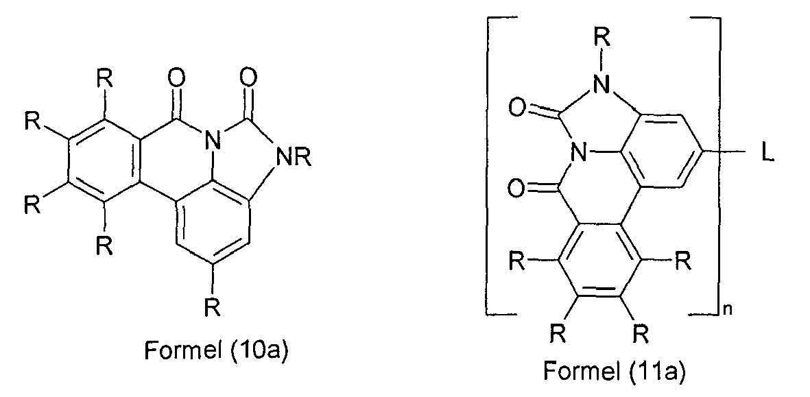
Bevorzugte Ausführungsformen der Formeln (10a) und (11a) sind die Verbindungen der folgenden Formeln (10b) und (11b),

Besonders bevorzugte Ausführungsformen sind die Verbindungen der folgenden Formeln (10c) und (11 c),

Bevorzugt sind weiterhin Strukturen, in denen der Rest R, der in Formel (9) bis (11) und (10a) bis (11 c) an den Stickstoff gebunden ist, für eine Gruppe C(=O)Ar1 steht, die mit einem benachbarten Rest R einen Ring bildet. Dadurch sind dann Verbindungen der folgenden Formeln (12) zugänglich,

Bevorzugt steht L in den Verbindungen der Formel (1) bzw. den oben aufgeführten bevorzugten Verbindungen für n = 2 für eine Einfachbindung, CR2, O, NR oder C(=O) oder für n = 3 für N oder für n ≥ 2 für für ein aromatisches oder heteroaromatisches Ringsystem mit 5 bis 24 aromatischen Ringatomen, das mit einem oder mehreren Resten R substituiert sein kann. Geeignete aromatische oder heteroaromatische Ringsysteme sind ortho-, meta- oder para-Phenylen, Fluoren, Spirobifluoren, Pyridin, Pyrimidin, Triazin, Carbazol, Dibenzofuran, Triphenylamin oder Kombinationen aus zwei oder drei dieser Gruppen. Dabei ist für n = 2 das aromatische bzw. heteroaromatische Ringsystem ein bivalentes System, für n = 3 ein trivalentes System, etc.. Besonders bevorzugt ist n = 2, und L steht für eine Einfachbindung.In the compounds of the formula (1) or the preferred compounds listed above, L preferably stands for n = 2 for a single bond, CR 2 , O, NR or C (= O) or for n = 3 for N or for n ≥ 2 for an aromatic or heteroaromatic ring system having from 5 to 24 aromatic ring atoms, which may be substituted by one or more R radicals. Suitable aromatic or heteroaromatic ring systems are ortho, meta or para-phenylene, fluorene, spirobifluorene, pyridine, pyrimidine, triazine, carbazole, dibenzofuran, triphenylamine or combinations of two or three of these groups. In this case, for n = 2, the aromatic or heteroaromatic ring system is a bivalent system, for n = 3 a trivalent system, etc. Particular preference is given to n = 2, and L is a single bond.
Bevorzugt weisen die erfindungsgemäßen Verbindungen mindestens eine Gruppe R ungleich Wasserstoff oder Deuterium auf, und/oder es handelt sich um eine Verbindung mit n >1.The compounds according to the invention preferably have at least one group R other than hydrogen or deuterium, and / or a compound with n> 1.
Der Rest R ungleich Wasserstoff ist bevorzugt ausgewählt aus der Gruppe bestehend aus einem aromatischen oder heteroaromatischen Ringsystem mit 5 bis 24 aromatischen Ringatomen, welches durch einen oder mehrere Reste R1 substituiert sein kann. Dies gilt insbesondere auch für den Rest R, der an ein Stickstoffatom gebunden ist, wenn Y für NR steht. Geeignete Aryl- bzw. Heteroarylgruppen, aus denen das aromatische Ringsystem zusammengesetzt sind, sind bevorzugt ausgewählt aus der Gruppe bestehend aus Benzol, Naphthalin, Phenanthren, Triphenylen, Pyridin, Thiophen, Furan, Pyrrol, Carbazol, Fluoren, Benzofuran, Benzothiophen, Dibenzofuran, Dibenzothiophen, Chinolin, Isochinolin, Phenanthridin, Phenanthrolin, Azacarbazol, Imidazol und Benzimidazol, welche jeweils mit einem oder mehreren Resten R1 substituiert sein können. Weiterhin bevorzugte Reste R sind aromatische bzw. heteroaromatische Aminogruppen, wobei die Aryl- bzw. Heteroarylgruppen durch einen oder mehrere Reste R1 substituiert sein können.The radical R other than hydrogen is preferably selected from the group consisting of an aromatic or heteroaromatic ring system having 5 to 24 aromatic ring atoms, which may be substituted by one or more radicals R 1 . This also applies in particular to the radical R which is bonded to a nitrogen atom when Y is NR. Suitable aryl or heteroaryl groups of which the aromatic ring system is composed are preferably selected from the group consisting of benzene, naphthalene, phenanthrene, triphenylene, pyridine, thiophene, furan, pyrrole, carbazole, fluorene, benzofuran, benzothiophene, dibenzofuran, dibenzothiophene , Quinoline, isoquinoline, phenanthridine, phenanthroline, azacarbazole, imidazole and benzimidazole, each of which may be substituted with one or more R 1 . Further preferred radicals R are aromatic or heteroaromatic amino groups, where the aryl or heteroaryl groups may be substituted by one or more radicals R 1 .
Wenn die erfindungsgemäße Verbindung als Matrixmaterial für einen phosphoreszierenden Emitter eingesetzt wird, enthält bevorzugt keine der Aryl- oder Heteroarylgruppen, die das aromatische bzw. heteroaromatische Ringsystem bilden oder die in der aromatischen bzw. heteroaromatischen Aminogruppe vorliegen, mehr als zwei direkt aneinander kondensierte aromatische Sechsringe. Bevorzugt enthalten die Reste R überhaupt keine direkt aneinander kondensierten aromatischen Sechsringe. Unter einer Aryl- oder Heteroarylgruppe mit nicht mehr als zwei direkt aneinander kondensierten aromatischen Sechsringen werden einfache Aryl- oder Heteroarylgruppen, wie zum Beispiel Benzol oder Pyridin, oder Aryl- oder Heteroarylgruppen mit genau zwei aneinander kondensierten aromatischen Sechsringen, wie zum Beispiel Naphthalin oder Chinolin verstanden. Weiterhin werden hierunter Heteroarylgruppen verstanden, in denen aromatische Fünfringe und Sechsringe, aber nicht aromatische Sechsringe direkt aneinander ankondensiert sind, wie zum Beispiel Carbazol, Dibenzofuran, Dibenzothiophen oder Benzimidazol. Weiterhin können auch Phenanthren oder Triphenylen geeignet sein.When the compound of the invention is used as a matrix material for a phosphorescent emitter, preferably none of the aryl or heteroaryl groups forming the aromatic or heteroaromatic ring system or present in the aromatic or heteroaromatic amino group contains more than two aromatic six-membered rings fused directly together. The radicals R preferably contain no aromatic six-membered rings condensed directly together. An aryl or heteroaryl group having not more than two directly condensed aromatic six-membered rings are understood as meaning simple aryl or heteroaryl groups, such as, for example, benzene or pyridine, or aryl or heteroaryl groups having exactly two aromatic six-membered rings condensed together, for example naphthalene or quinoline , Furthermore, these are understood to mean heteroaryl groups in which aromatic five-membered rings and six-membered rings, but non-aromatic six-membered rings, are directly fused to one another, such as, for example, carbazole, dibenzofuran, dibenzothiophene or benzimidazole. Furthermore, phenanthrene or triphenylene may be suitable.
Bevorzugte Gruppen R sind ausgewählt aus der Gruppe bestehend aus Benzol, Biphenyl, insbesondere ortho-, meta- oder para-Biphenyl, Terphenyl, insbesondere ortho-, meta-, para- oder verzweigtes Terphenyl, Quaterphenyl, insbesondere ortho-, meta- oder para-verknüpftes, lineares oder verzweigtes Quaterphenyl, Fluoren, insbesondere 1-, 2-, 3- oder 4-Fluoren, Spirobifluoren, insbesondere 1-, 2-, 3- oder 4-Spirobifluoren, 1-oder 2-Naphthalin, Pyrrol, Furan, Thiophen, Indol, Benzofuran, Benzothiophen, Carbazol, insbesondere 1-, 2-, 3- oder 4-Carbazol oder N-Carbazol, Dibenzothiophen, insbesondere 1-, 2-, 3- oder 4-Dibenzothiophen, Dibenzofuran, insbesondere 1-, 2-, 3- oder 4-Dibenzofuran, 1,3,5-Triazin, Pyridin, Pyrimidin, Pyrazin, Pyridazin, Indenocarbazol, verbrücktes Carbazol, Indolocarbazol, Phenanthren, Triphenylen oder Kombinationen aus zwei oder drei dieser Gruppen. Dabei können diese Gruppen jeweils durch einen oder mehrere Reste R1 substituiert sein.Preferred groups R are selected from the group consisting of benzene, biphenyl, in particular ortho, meta or para biphenyl, terphenyl, in particular ortho, meta, para or branched terphenyl, quaterphenyl, in particular ortho, meta or para -linked, linear or branched quaterphenyl, fluorene, in particular 1-, 2-, 3- or 4-fluorene, spirobifluorene, in particular 1-, 2-, 3- or 4-spirobifluorene, 1- or 2-naphthalene, pyrrole, furan , Thiophene, indole, benzofuran, benzothiophene, carbazole, in particular 1-, 2-, 3- or 4-carbazole or N-carbazole, dibenzothiophene, in particular 1-, 2-, 3- or 4-dibenzothiophene, dibenzofuran, in particular 1- , 2-, 3- or 4-dibenzofuran, 1,3,5-triazine, pyridine, pyrimidine, pyrazine, pyridazine, indenocarbazole, bridged carbazole, indolocarbazole, phenanthrene, triphenylene or combinations of two or three of these groups. These groups may each be substituted by one or more radicals R 1 .
Wenn R für ein aromatisches bzw. heteroaromatisches Ringsystem steht, dann ist dieses bevorzugt ausgewählt aus den Gruppen der folgenden Formeln (R-1) bis (R-33),
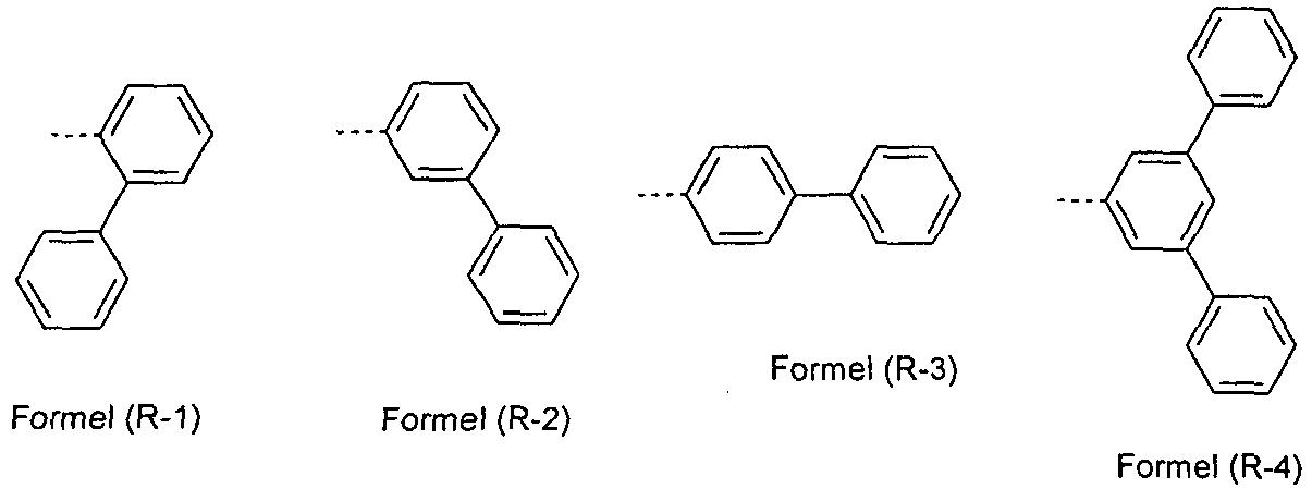


Wenn die erfindungsgemäßen Verbindungen als Elektronentransportmaterial verwendet werden, ist es bevorzugt, wenn mindestens eine der Gruppen R und/oder L für ein elektronenarmes heteroaromatisches Ringsystem oder -C(=O)Ar1 oder -P(=O)(Ar1)2 steht. Elektronenarme Heteroaromaten sind erfindungsgemäß Fünfringheteroaromaten mit mindestens zwei Heteroatomen oder Sechsringheteroaromaten, an die jeweils noch ein oder mehrere aromatische oder heteroaromatische Gruppen ankondensiert sein können, zum Beispiel substituierte oder unsubstituierte Imidazole, Pyrazole, Thiazole, Oxazole, Oxadiazole, Triazole, Pyridine, Pyrazine, Pyrimidine, Pyridazine, Triazine, Benzimidazole, etc., insbesondere solche, wie sie im Folgenden aufgeführt sind. Bevorzugte Gruppen R und/oder L sind weiterhin auch substituierte oder unsubstituierte kondensierte Arylgruppen, insbesondere Naphthalin, Anthracen, Pyren, Phenanthren, Triphenylen und Benzanthracen.When the compounds of the invention are used as the electron transport material, it is preferable that at least one of R and / or L is an electron-deficient heteroaromatic ring system or -C (= O) Ar 1 or -P (= O) (Ar 1 ) 2 , Low-electron heteroaromatics according to the invention are five-membered heteroaromatics having at least two heteroatoms or six-membered heteroaromatics, to each of which one or more aromatic or heteroaromatic groups may be fused, for example substituted or unsubstituted imidazoles, pyrazoles, thiazoles, oxazoles, oxadiazoles, triazoles, pyridines, pyrazines, pyrimidines, Pyridazines, triazines, benzimidazoles, etc., in particular those as they are listed below. Preferred groups R and / or L are furthermore also substituted or unsubstituted condensed aryl groups, in particular naphthalene, anthracene, pyrene, phenanthrene, triphenylene and benzanthracene.
Wenn die erfindungsgemäße Verbindung bzw. die oben aufgeführten bevorzugten Verbindungen als Matrixmaterial für einen phosphoreszierenden Emitter oder als Elektronentransportmaterial eingesetzt wird, ist es weiterhin bevorzugt, wenn mindestens eine Gruppe R eine einfache aromatische Gruppe oder eine elektronenarme Gruppe darstellt, insbesondere ausgewählt aus Strukturen gemäß den folgenden Formeln (13) bis (16) für R oder den Formeln (17), (18) oder (19) für L,


- A ist bei jedem Auftreten gleich oder verschieden CR1 oder N, mit der Maßgabe, dass keine, eine, zwei oder drei Gruppen A für N stehen;
- Ar2 ist gleich oder verschieden bei jedem Auftreten ein bivalentes aromatisches oder heteroaromatisches Ringsystem mit 5 bis 16 C-Atomen, welches durch einen oder mehrere Reste R1 substituiert sein kann;
- m ist bei jedem Auftreten gleich oder verschieden 0 oder 1.
- A is the same or different CR 1 or N on each occurrence, with the proviso that none, one, two or three groups A are N;
- Ar 2 is identical or different at each occurrence, a bivalent aromatic or heteroaromatic ring system having 5 to 16 carbon atoms, which may be substituted by one or more radicals R 1 ;
- m is the same or different 0 or 1 at each occurrence.
Als Matrixmaterial für phosphoreszierende Emitter sind weiterhin auch generell die oben aufgeführten aromatischen und heteroaromatischen Ringsysteme bevorzugt, die allgemein als bevorzugte Reste R genannt sind.As a matrix material for phosphorescent emitters, the above-mentioned aromatic and heteroaromatic ring systems which are generally mentioned as preferred radicals R are also generally preferred.
In einer besonders bevorzugten Ausführungsform der Erfindung steht mindestens ein Substituent R für eine Gruppe der oben genannten Formel (R-1) bis (R-17) oder Formel (13), und/oder mindestens eine Gruppe L steht für eine Gruppe der oben genannten Formeln (17) bis (19), wobei jeweils zwei oder drei Symbole A für N stehen und die anderen Symbole A für CR1 stehen. Besonders bevorzugte Gruppen R sind daher die Gruppen der folgenden Formeln (20) bis (26), und besonders bevorzugte Gruppen L sind die Gruppen der folgenden Formeln (27) bis (34),
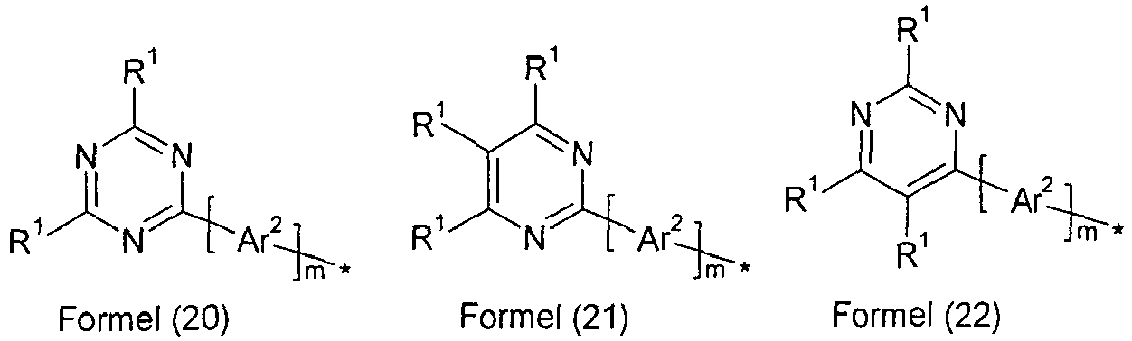


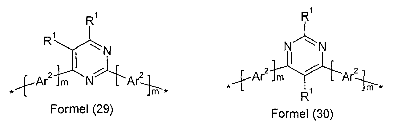


Wenn R für eine Gruppe der Formel (20) steht, dann steht R1 in dieser Gruppe bevorzugt für ein aromatisches oder heteroaromatisches Ringsystem mit 5 bis 24 aromatischen Ringatomen, welches durch eine oder mehrere Alkylgruppen mit 1 bis 10 C-Atomen substituiert sein kann, insbesondere für Phenyl, Biphenyl, insbesondere ortho-, meta- oder para-Biphenyl, Terphenyl, insbesondere ortho-, meta-, para- oder verzweigtes Terphenyl, oder Quaterphenyl, insbesondere ortho-, meta-, para- oder verzweigtes Quaterphenyl.When R is a group of the formula (20), then R 1 in this group is preferably an aromatic or heteroaromatic ring system having 5 to 24 aromatic ring atoms, which may be substituted by one or more alkyl groups having 1 to 10 C atoms, in particular phenyl, biphenyl, in particular ortho, meta or para biphenyl, terphenyl, in particular ortho, meta, para or branched terphenyl, or quaterphenyl, in particular ortho, meta, para or branched quaterphenyl.
Wenn R für eine Gruppe der Formel (21) bis (34) steht, dann steht R1 in diesen Gruppen bevorzugt gleich oder verschieden bei jedem Auftreten für H, D oder ein aromatisches oder heteroaromatisches Ringsystem mit 5 bis 24 aromatischen Ringatomen, welches durch eine oder mehrere Alkylgruppen mit 1 bis 10 C-Atomen substituiert sein kann, insbesondere für H oder Phenyl, Biphenyl, insbesondere ortho-, meta- oder para-Biphenyl, Terphenyl, insbesondere ortho-, meta-, para- oder verzweigtes Terphenyl, oder Quaterphenyl, insbesondere ortho-, meta-, para- oder verzweigtes Quaterphenyl.When R is a group of the formula (21) to (34), then R 1 in these groups is preferably the same or different at each occurrence of H, D or an aromatic or heteroaromatic ring system having 5 to 24 aromatic ring atoms, which is replaced by a or more alkyl groups having 1 to 10 carbon atoms, in particular for H or phenyl, biphenyl, in particular ortho, meta or para biphenyl, Terphenyl, in particular ortho, meta, para or branched terphenyl, or quaterphenyl, in particular ortho, meta, para or branched quaterphenyl.
Wenn die erfindungsgemäße Verbindung als Matrixmaterial für einen phosphoreszierenden Emitter eingesetzt wird, kann es weiterhin bevorzugt sein, wenn mindestens ein Substituent R ausgewählt ist aus der Gruppe bestehend aus Triaryl- bzw. Heteroarylaminderivaten, Carbazolderivaten, Indenocarbazolderivaten, Indolocarbazolderivaten, Azacarbazolderivaten, Indolderivaten, Furanderivaten, Benzofuranderivaten, Dibenzofuranderivaten, Thiophenderivaten, Benzothiophenderivaten oder Dibenzothiophenderivaten, welche jeweils durch einen oder mehrere Reste R1 substituiert sein können, oder mindestens ein Substituent R steht für -N(Ar1)2. Diese Gruppen sind bevorzugt ausgewählt aus den Gruppen der folgenden Formeln (35) bis (59),


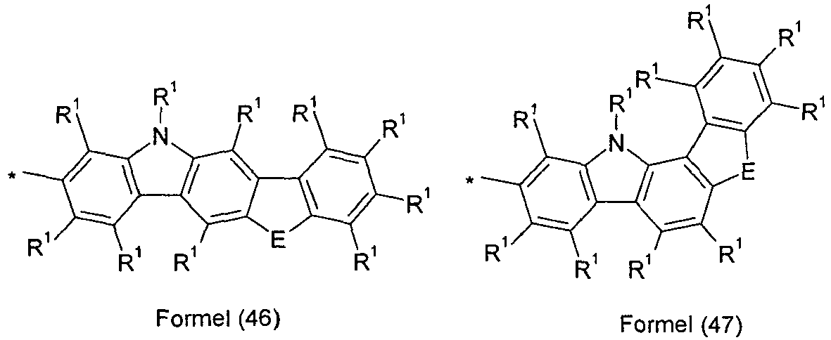


- E ist ausgewählt aus der Gruppe bestehend aus C(R1)2, NR1, O oder S;
- G ist ausgewählt aus der Gruppe bestehend aus NR1, O oder S.
- E is selected from the group consisting of C (R 1 ) 2 , NR 1 , O or S;
- G is selected from the group consisting of NR 1 , O or S.
Die oben genannten bevorzugten Ausführungsformen können beliebig miteinander kombiniert werden. In einer besonders bevorzugten Ausführungsform der Erfindung treten die oben genannten Bevorzugungen gleichzeitig auf.The above-mentioned preferred embodiments can be arbitrarily combined with each other. In a particularly preferred embodiment of the invention, the abovementioned preferences occur simultaneously.
Wenn die Verbindungen der Formel (1) bzw. die bevorzugten Ausführungsformen als Matrixmaterial für einen fluoreszierenden Emitter oder als fluoreszierender Emitter verwendet werden, ist es bevorzugt, wenn mindestens einer der Reste R eine Gruppe enthält, die ausgewählt ist aus Naphthalin, Anthracen, Phenanthren, Pyren und/oder Benzanthracen, welches jeweils noch durch eine oder mehrere Gruppen R1 substituiert sein kann.When the compounds of the formula (1) or the preferred embodiments are used as a matrix material for a fluorescent emitter or as a fluorescent emitter, it is preferred that at least one of the radicals R contains a group which is selected from Naphthalene, anthracene, phenanthrene, pyrene and / or benzanthracene, which may each be substituted by one or more groups R 1 .
In einer bevorzugten Ausführungsform der Erfindung sind die Reste R in den erfindungsgemäßen Verbindungen, die nicht für die oben genannten Gruppen stehen, gleich oder verschieden bei jedem Auftreten ausgewählt aus der Gruppe bestehend aus H, D, F, CN, N(Ar2)2, C(=O)Ar2, einer geradkettigen Alkyl- oder Alkoxygruppe mit 1 bis 10 C-Atomen oder einer verzweigten oder cyclischen Alkyl- oder Alkoxygruppe mit 3 bis 10 C-Atomen oder einer Alkenylgruppe mit 2 bis 10 C-Atomen, die jeweils mit einem oder mehreren Resten R2 substituiert sein kann, wobei eine oder mehrere nicht-benachbarte CH2-Gruppen durch O ersetzt sein können und wobei ein oder mehrere H-Atome durch D oder F ersetzt sein können oder einem aromatischen oder heteroaromatischen Ringsystem mit 5 bis 30 aromatischen Ringatomen, das jeweils mit einem oder mehreren Resten R2 substituiert sein kann. Besonders bevorzugt ist R gleich oder verschieden bei jedem Auftreten ausgewählt aus der Gruppe bestehend aus H, einer geradkettigen Alkylgruppe mit 1 bis 10 C-Atomen oder einer verzweigten oder cyclischen Alkylgruppe mit 3 bis 10 C-Atomen, die jeweils mit einem oder mehreren Resten R2 substituiert sein kann, oder einem aromatischen oder heteroaromatischen Ringsystem mit 5 bis 18 aromatischen Ringatomen, das jeweils mit einem oder mehreren Resten R2 substituiert sein kann.In a preferred embodiment of the invention, the radicals R in the compounds according to the invention which do not stand for the abovementioned groups are identical or different at each occurrence and are selected from the group consisting of H, D, F, CN, N (Ar 2 ) 2 , C (= O) Ar 2 , a straight-chain alkyl or alkoxy group having 1 to 10 C atoms or a branched or cyclic alkyl or alkoxy group having 3 to 10 C atoms or an alkenyl group having 2 to 10 C atoms, the each may be substituted with one or more radicals R 2 , wherein one or more non-adjacent CH 2 groups may be replaced by O and wherein one or more H atoms may be replaced by D or F or an aromatic or heteroaromatic ring system with 5 to 30 aromatic ring atoms, each of which may be substituted by one or more radicals R 2 . More preferably, R is the same or different at each occurrence selected from the group consisting of H, a straight chain alkyl group having 1 to 10 carbon atoms or a branched or cyclic alkyl group having 3 to 10 carbon atoms, each having one or more R radicals 2 may be substituted, or an aromatic or heteroaromatic ring system having 5 to 18 aromatic ring atoms, which may be substituted in each case with one or more radicals R 2 .
Dabei haben für Verbindungen, die durch Vakuumverdampfung verarbeitet werden, die Alkylgruppen bevorzugt nicht mehr als fünf C-Atome, besonders bevorzugt nicht mehr als 4 C-Atome, ganz besonders bevorzugt nicht mehr als 1 C-Atom. Für Verbindungen, die aus Lösung verarbeitet werden, eignen sich auch Verbindungen, die mit Alkylgrupp'en mit bis zu 10 C-Atomen substituiert sind oder die mit Oligoarylengruppen, beispielsweise ortho-, meta-, para- oder verzweigten Terphenyl- oder Quaterphenylgruppen, substituiert sind.In this case, for compounds which are processed by vacuum evaporation, the alkyl groups preferably have not more than five carbon atoms, more preferably not more than 4 carbon atoms, most preferably not more than 1 carbon atom. For compounds which are processed from solution, compounds which are substituted by alkyl groups having up to 10 carbon atoms or which are substituted by oligoarylene groups, for example ortho, meta, para or branched terphenyl or quaterphenyl groups are also suitable are.
In einer besonders bevorzugten Ausführungsform der Erfindung treten die oben genannten Bevorzugungen gleichzeitig auf.In a particularly preferred embodiment of the invention, the abovementioned preferences occur simultaneously.
Beispiele für bevorzugte erfindungsgemäße Verbindungen sind die in der folgenden Tabelle abgebildeten Verbindungen.


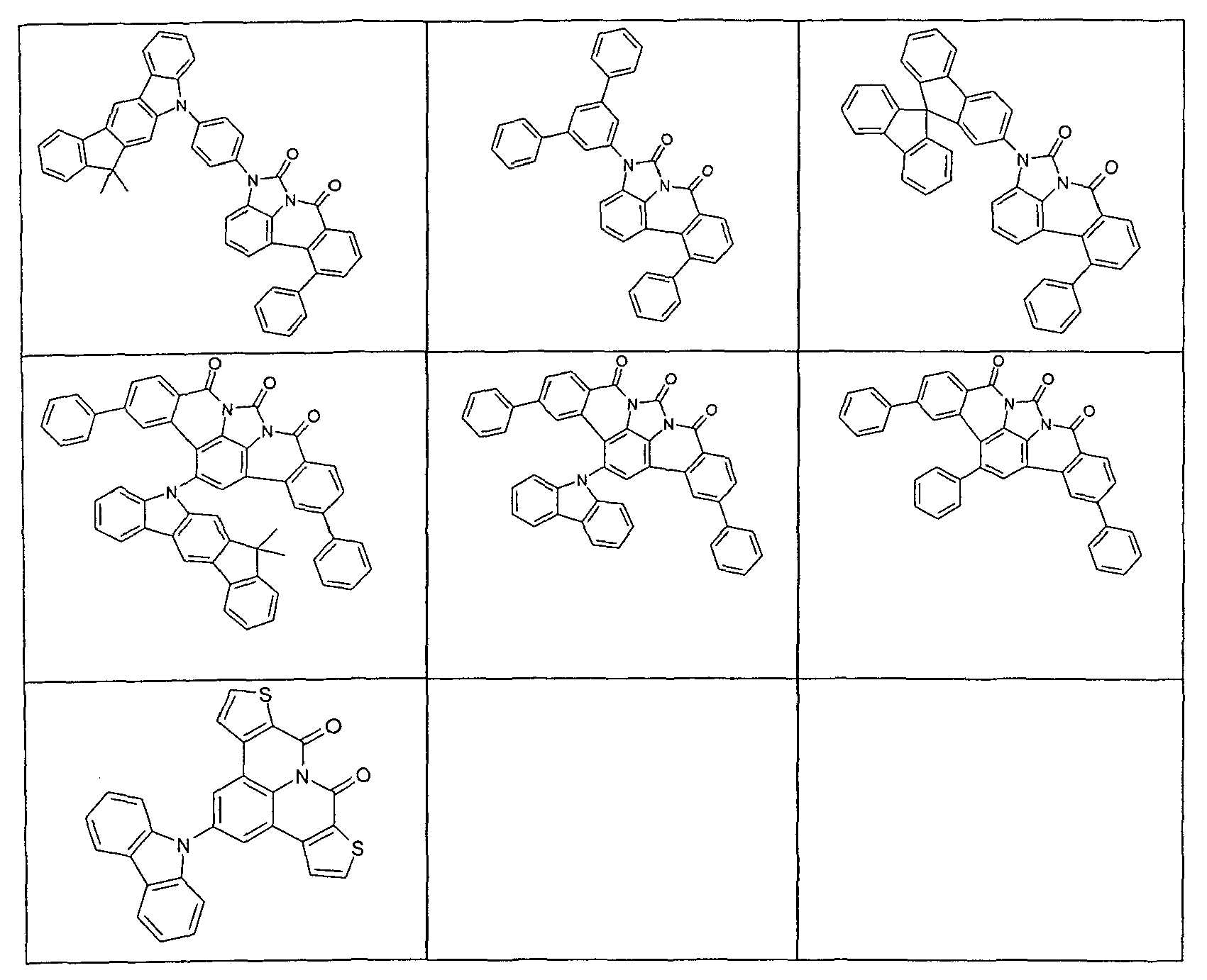
Die erfindungsgemäßen Verbindungen können nach dem Fachmann prinzipiell bekannten Syntheseschritten dargestellt werden, wie in Schema 1 und 2 schematisch dargestellt.The compounds according to the invention can be prepared by synthesis steps which are known in principle to the person skilled in the art, as shown schematically in Schemes 1 and 2.
Wie in Schema 1 dargestellt, erhält man nach einer Schmidt-Reaktion und anschließender Reduktion das entsprechende 5,6-Dihydrophenanthridin-Derivat (a), das unter Verwendung von in ortho-Stellung Halogen-substituiertem Carbonsäurehalogenid und anschließender Palladium-katalysierter intramolekularer Cyclisierung zum 8a-Aza-benzo[fg]naphthacen-8,9-dion umgesetzt wird. Durch Halogenierung, beispielsweise Bromierung mit NBS, kann dieser Grundbaustein halogeniert werden. In einer Folgereaktion kann beispielsweise mit einer Suzuki-Kupplung, einer Buchwald- oder Ullmann-Reaktion zum gewünschten Derivat umgesetzt werden.

Alternativ kann an Stelle des in ortho-Position Halogen-substituierten Carbonsäurehalogenids ein ortho-substituiertes Halogen-benzylhalogenid eingesetzt werden, wie in Schema 2 dargestellt.

Ein weiterer Gegenstand der vorliegenden Erfindung ist ein Verfahren zur Herstellung einer Verbindung gemäß Formel (1), umfassend die Schritte:
- a) Herstellung des halogenierten Grundgerüsts der Verbindung der Formel (1), wobei das Halogen bevorzugt Chlor, Brom oder Iod ist; und
- b) Einführung mindestens eines Substituenten R in der Position des Halogens.
- a) preparation of the halogenated skeleton of the compound of formula (1), wherein the halogen is preferably chlorine, bromine or iodine; and
- b) introduction of at least one substituent R in the position of the halogen.
Für die Verarbeitung der erfindungsgemäßen Verbindungen aus flüssiger Phase, beispielsweise durch Spin-Coating oder durch Druckverfahren, sind Formulierungen der erfindungsgemäßen Verbindungen erforderlich. Diese Formulierungen können beispielsweise Lösungen, Dispersionen oder Emulsionen sein. Es kann bevorzugt sein, hierfür Mischungen aus zwei oder mehr Lösemitteln zu verwenden. Geeignete und bevorzugte Lösemittel sind beispielsweise Toluol, Anisol, o-, m- oder p-Xylol, Methylbenzoat, Mesitylen, Tetralin, Veratrol, THF, Methyl-THF, THP, Chlorbenzol, Dioxan, Phenoxytoluol, insbesondere 3-Phenoxytoluol, (-)-Fenchon, 1,2,3,5-Tetramethylbenzol, 1,2,4,5-Tetramethylbenzol, 1-Methylnaphthalin, 2-Methylbenzothiazol, 2-Phenoxyethanol, 2-Pyrrolidinon, 3-Methylanisol, 4-Methylanisol, 3,4-Dimethylanisol, 3,5-Dimethylanisol, Acetophenon, α-Terpineol, Benzothiazol, Butylbenzoat, Cumol, Cyclohexanol, Cyclohexanon, Cyclohexylbenzol, Decalin, Dodecylbenzol, Ethylbenzoat, Indan, Methylbenzoat, NMP, p-Cymol, Phenetol, 1,4-Diisopropylbenzol, Dibenzylether, Diethylenglycolbutylmethylether, Triethylenglycolbutylmethylether, Diethylenglycoldibutylether, Triethylenglycoldimethylether, Diethylenglycolmonobutylether, Tripropyleneglycoldimethylether, Tetraethyleneglycoldimethylether, 2-lsopropylnaphthalin, Pentylbenzol, Hexylbenzol, Heptylbenzol, Octylbenzol, 1,1-Bis(3,4-dimethylphenyl)ethan oder Mischungen dieser Lösemittel.For the processing of the compounds according to the invention from the liquid phase, for example by spin coating or by printing processes, formulations of the compounds according to the invention are required. These formulations may be, for example, solutions, dispersions or emulsions. It may be preferable to use mixtures of two or more solvents for this purpose. Suitable and preferred solvents are, for example, toluene, anisole, o-, m- or p-xylene, methyl benzoate, mesitylene, tetralin, veratrol, THF, methyl THF, THP, chlorobenzene, dioxane, phenoxytoluene, in particular 3-phenoxytoluene, (-) -Fenchone, 1,2,3,5-tetramethylbenzene, 1,2,4,5-tetramethylbenzene, 1-methylnaphthalene, 2-methylbenzothiazole, 2-phenoxyethanol, 2-pyrrolidinone, 3-methylanisole, 4-methylanisole, 3,4 Dimethylanisole, 3,5-dimethylanisole, acetophenone, α-terpineol, benzothiazole, butylbenzoate, cumene, cyclohexanol, cyclohexanone, cyclohexylbenzene, decalin, dodecylbenzene, ethylbenzoate, indane, methylbenzoate, NMP, p-cymene, phenetole, 1,4-diisopropylbenzene , Dibenzyl ether, diethylene glycol butyl methyl ether, triethylene glycol butyl methyl ether, diethylene glycol dibutyl ether, triethylene glycol dimethyl ether, diethylene glycol monobutyl ether, tripropylene glycol dimethyl ether, tetraethylene glycol dimethyl ether, 2-isopropylnaphthalene, pentylbenzene, hexylbenzene, heptylbenzene, octylbenzene, 1,1-bis (3,4-dimethylpheny l) ethane or mixtures of these solvents.
Ein weiterer Gegenstand der vorliegenden Erfindung ist daher eine Formulierung, enthaltend eine erfindungsgemäße Verbindung und mindestens eine weitere Verbindung. Die weitere Verbindung kann beispielsweise ein Lösemittel sein, insbesondere eines der oben genannten Lösemittel oder eine Mischung dieser Lösemittel. Die weitere Verbindung kann aber auch eine weitere organische oder anorganische Verbindung sein, die ebenfalls in der elektronischen Vorrichtung eingesetzt wird, beispielsweise eine emittierende Verbindung, insbesondere eine phosphoreszierende Verbindung.A further subject of the present invention is therefore a formulation containing a compound according to the invention and at least one further compound. The further compound may be for example a solvent, in particular one of the abovementioned solvents or a mixture of these solvents. The further connection can also be another organic or inorganic compound which is also used in the electronic device, for example an emitting compound, in particular a phosphorescent compound.
Ein weiterer Gegenstand der vorliegenden Erfindung ist die Verwendung der erfindungsgemäßen Verbindungen in einer elektronischen Vorrichtung, insbesondere in einer organischen Elektrolumineszenzvorrichtung.Another object of the present invention is the use of the compounds of the invention in an electronic device, in particular in an organic electroluminescent device.
Die organischen Elektrolumineszenzvorrichtungen und die lichtemittierenden elektrochemischen Zellen können für verschiedene Anwendungen eingesetzt werden, beispielsweise für einfarbige oder mehrfarbige Displays, für Beleuchtungsanwendungen oder für medizinische und/oder kosmetische Anwendungen, beispielsweise in der Phototherapie.The organic electroluminescent devices and the light-emitting electrochemical cells can be used for various applications, for example for monochrome or multicolor displays, for lighting applications or for medical and / or cosmetic applications, for example in phototherapy.
Eine elektronische Vorrichtung im Sinne der vorliegenden Erfindung ist eine Vorrichtung, welche mindestens eine Schicht enthält, die mindestens eine organische Verbindung enthält. Das Bauteil kann dabei auch anorganische Materialien enthalten oder auch Schichten, welche vollständig aus anorganischen Materialien aufgebaut sind.An electronic device in the sense of the present invention is a device which contains at least one layer which contains at least one organic compound. The component may also contain inorganic materials or layers which are completely composed of inorganic materials.
Die elektronische Vorrichtung ist bevorzugt ausgewählt aus der Gruppe bestehend aus organischen Elektrolumineszenzvorrichtungen (OLEDs), organischen integrierten Schaltungen (O-ICs), organischen Feld-Effekt-Transistoren (O-FETs), organischen Dünnfilmtransistoren (O-TFTs), organischen lichtemittierenden Transistoren (O-LETs), organischen Solarzellen (O-SCs), organischen farbstoffsensibilisierten Solarzellen (O-DSSC), organischen optischen Detektoren, organischen Photorezeptoren, organischen Feld-Quench-Devices (O-FQDs), lichtemittierenden elektrochemischen Zellen (LECs), organischen Laserdioden (O-Laser) und "organic plasmon emitting devices" (
Die organische Elektrolumineszenzvorrichtung enthält Kathode, Anode und mindestens eine emittierende Schicht. Außer diesen Schichten kann sie noch weitere Schichten enthalten, beispielsweise jeweils eine oder mehrere Lochinjektionsschichten, Lochtransportschichten, Lochblockierschichten, Elektronentransportschichten, Elektroneninjektionsschichten, Exzitonenblockierschichten, Elektronenblockierschichten und/oder Ladungserzeugungsschichten (Charge-Generation Layers). Ebenso können zwischen zwei emittierende Schichten Intetlayer eingebracht sein, welche beispielsweise eine exzitonenblockierende Funktion aufweisen. Es sei aber darauf hingewiesen, dass nicht notwendigerweise jede dieser Schichten vorhanden sein muss. Dabei kann die organische Elektrolumineszenzvorrichtung eine emittierende Schicht enthalten, oder sie kann mehrere emittierende Schichten enthalten. Wenn mehrere Emissionsschichten vorhanden sind, weisen diese bevorzugt insgesamt mehrere Emissionsmaxima zwischen 380 nm und 750 nm auf, so dass insgesamt weiße Emission resultiert, d. h. in den emittierenden Schichten werden verschiedene emittierende Verbindungen verwendet, die fluoreszieren oder phosphoreszieren können. Insbesondere bevorzugt sind Systeme mit drei emittierenden Schichten, wobei die drei Schichten blaue, grüne und orange oder rote Emission zeigen (für den prinzipiellen Aufbau siehe z. B.
Die Verbindung gemäß Formel (1) kann dabei in unterschiedlichen Schichten eingesetzt werden, je nach genauer Struktur. Bevorzugt ist eine organische Elektrolumineszenzvorrichtung, enthaltend eine Verbindung gemäß Formel (1) bzw. die oben ausgeführten bevorzugten Ausführungsformen als Matrixmaterial für fluoreszierende oder phosphoreszierende Emitter, insbesondere für phosphoreszierende Emitter, und/oder in einer Lochblockierschicht und/oder in einer Elektronentransportschicht und/oder in einer elektronenblockierenden bzw. exzitonenblockierenden Schicht und/oder in einer Lochtransportschicht, je nach genauer Substitution.The compound according to formula (1) can be used in different layers, depending on the exact structure. Preference is given to an organic electroluminescent device comprising a compound according to formula (1) or the preferred embodiments described above as matrix material for fluorescent or phosphorescent emitters, in particular for phosphorescent emitters, and / or in a hole blocking layer and / or in an electron transport layer and / or in an electron-blocking or exciton-blocking layer and / or in a hole transport layer, depending on the exact substitution.
In einer weiteren Ausführungsform der Erfindung enthält die organische Elektrolumineszenzvorrichtung die Verbindung gemäß Formel (1) bzw. die oben ausgeführten bevorzugten Ausführungsformen in einer optischen Auskopplungsschicht. Unter einer optischen Auskopplungsschicht wird dabei eine Schicht verstanden, die nicht zwischen der Anode und der Kathode liegt, sondern die außerhalb der eigentlichen Vorrichtung auf eine Elektrode aufgebracht wird, beispielsweise zwischen einer Elektrode und einem Substrat, um die optische Auskopplung zu verbessern.In a further embodiment of the invention, the organic electroluminescent device contains the compound according to formula (1) or the The above-described preferred embodiments in an optical coupling-out layer. An optical coupling-out layer is understood to be a layer which does not lie between the anode and the cathode, but which is applied to an electrode outside the actual device, for example between an electrode and a substrate, in order to improve the optical coupling-out.
In einer bevorzugten Ausführungsform der Erfindung wird die erfindungsgemäße Verbindung als Matrixmaterial für eine fluoreszierende oder phosphoreszierende Verbindung, insbesondere für eine phosphoreszierende Verbindung, in einer emittierenden Schicht eingesetzt. Dabei kann die organische Elektrolumineszenzvorrichtung eine emittierende Schicht enthalten, oder sie kann mehrere emittierende Schichten enthalten, wobei mindestens eine emittierende Schicht mindestens eine Verbindung gemäß Formel (1) als Matrixmaterial enthält.In a preferred embodiment of the invention, the compound according to the invention is used as matrix material for a fluorescent or phosphorescent compound, in particular for a phosphorescent compound, in an emitting layer. In this case, the organic electroluminescent device may contain an emitting layer, or it may contain a plurality of emitting layers, wherein at least one emitting layer contains at least one compound according to formula (1) as matrix material.
Wenn die Verbindung gemäß Formel (1) bzw. die oben ausgeführten bevorzugten Ausführungsformen als Matrixmaterial für eine emittierende Verbindung in einer emittierenden Schicht eingesetzt wird, wird sie bevorzugt in Kombination mit einem oder mehreren phosphoreszierenden Materialien (Triplettemitter) eingesetzt. Unter Phosphoreszenz im Sinne dieser Erfindung wird die Lumineszenz aus einem angeregten Zustand mit Spinmultiplizität > 1, insbesondere aus einem angeregten Triplettzustand verstanden. Im Sinne dieser Anmeldung sollen alle lumineszierenden Komplexe mit Übergangsmetallen oder Lanthaniden, insbesondere alle Iridium-, Platin- und Kupferkomplexe als phosphoreszierende Verbindungen angesehen werden.When the compound according to formula (1) or the preferred embodiments outlined above is used as the matrix material for an emitting compound in an emitting layer, it is preferably used in combination with one or more phosphorescent materials (triplet emitters). Phosphorescence in the sense of this invention is understood to mean the luminescence from an excited state with a spin multiplicity> 1, in particular from an excited triplet state. For the purposes of this application, all luminescent complexes with transition metals or lanthanides, in particular all iridium, platinum and copper complexes are to be regarded as phosphorescent compounds.
Die Mischung aus der Verbindung gemäß Formel (1) bzw. der oben ausgeführten bevorzugten Ausführungsformen und der emittierenden Verbindung enthält zwischen 99 und 1 Vol.-%, vorzugsweise zwischen 98 und 10 Vol.-%, besonders bevorzugt zwischen 97 und 60 Vol.-%, insbesondere zwischen 95 und 80 Vol.-% der Verbindung gemäß Formel (1) bzw. der oben ausgeführten bevorzugten Ausführungsformen bezogen auf die Gesamtmischung aus Emitter und Matrixmaterial. Entsprechend enthält die Mischung zwischen 1 und 99 Vol.-%, vorzugsweise zwischen 2 und 90 Vol.-%, besonders bevorzugt zwischen 3 und 40 Vol.-%, insbesondere zwischen 5 und 20 Vol.-% des Emitters bezogen auf die Gesamtmischung aus Emitter und Matrixmaterial. Je nach Wahl des Matrixmaterials kann auch eine geringere Emitterkonzentration bevorzugt sein, wie z. B. in der nicht offen gelegten Anmeldung
Eine weitere bevorzugte Ausführungsform der vorliegenden Erfindung ist der Einsatz der Verbindung gemäß Formel (1) bzw. der oben ausgeführten bevorzugten Ausführungsformen als Matrixmaterial für einen phosphoreszierenden Emitter in Kombination mit einem weiteren Matrixmaterial. Eine weitere bevorzugte Ausführungsform der vorliegenden Erfindung ist der Einsatz der Verbindung gemäß Formel (1) bzw. gemäß den bevorzugten Ausführungsformen als Matrixmaterial für einen phosphoreszierenden Emitter in Kombination mit einem weiteren Matrixmaterial. Besonders geeignete Matrixmaterialien, welche in Kombination mit den Verbindungen gemäß Formel (1) bzw. gemäß den bevorzugten Ausführungsformen eingesetzt werden können, sind aromatische Ketone, aromatische Phosphinoxide oder aromatische Sulfoxide oder Sulfone, z. B. gemäß
Als phosphoreszierende Verbindung (= Triplettemitter) eignen sich insbesondere Verbindungen, die bei geeigneter Anregung Licht, vorzugsweise im sichtbaren Bereich, emittieren und außerdem mindestens ein Atom der Ordnungszahl größer 20, bevorzugt größer 38 und kleiner 84, besonders bevorzugt größer 56 und kleiner 80 enthalten, insbesondere ein Metall mit dieser Ordnungszahl. Bevorzugt werden als Phosphoreszenzemitter Verbindungen, die Kupfer, Molybdän, Wolfram, Rhenium, Ruthenium, Osmium, Rhodium, Iridium, Palladium, Platin, Silber, Gold oder Europium enthalten, verwendet, insbesondere Verbindungen, die Iridium, Platin oder Kupfer enthalten.Suitable phosphorescent compounds (= triplet emitters) are, in particular, compounds which emit light, preferably in the visible range, with suitable excitation and also contain at least one atom of atomic number greater than 20, preferably greater than 38 and less than 84, particularly preferably greater than 56 and less than 80, in particular a metal with this atomic number. Preferred phosphorescence emitters used are compounds containing copper, molybdenum, tungsten, rhenium, ruthenium, osmium, rhodium, iridium, palladium, platinum, silver, gold or europium, in particular compounds containing iridium, platinum or copper.
Beispiele der oben beschriebenen Emitter können den Anmeldungen
In einer weiteren Ausführungsform der Erfindung enthält die erfindungsgemäße organische Elektrolumineszenzvorrichtung keine separate Lochinjektionsschicht und/oder Lochtransportschicht und/oder Lochblockierschicht und/oder Elektronentransportschicht, d. h. die emittierende Schicht grenzt direkt an die Lochinjektionschicht oder die Anode an, und/ oder die emittierende Schicht grenzt direkt an die Elektronentransportschicht oder die Elektroneninjektionsschicht oder die Kathode an, wie zum Beispiel in
In einer weiteren bevorzugten Ausführungsform der Erfindung wird die Verbindung gemäß Formel (1) bzw. die oben ausgeführten bevorzugten Ausführungsformen als Elektronentransportmaterial in einer Elektronentransport- oder Elektroneninjektionsschicht eingesetzt. Dabei kann die emittierende Schicht fluoreszierend oder phosphoreszierend sein. Wenn die Verbindung als Elektronentransportmaterial eingesetzt wird, kann es bevorzugt sein, wenn sie dotiert ist, beispielsweise mit Alkalimetallkomplexen, wie z. B. LiQ (Lithiumhydroxychinolinat).In a further preferred embodiment of the invention, the compound according to formula (1) or the above-described preferred embodiments is used as an electron transport material in an electron transport or electron injection layer. In this case, the emitting layer may be fluorescent or phosphorescent. When the compound is used as an electron transport material, it may be preferred if it is doped, for example, with alkali metal complexes, such as. B. LiQ (Lithiumhydroxychinolinat).
In nochmals einer weiteren bevorzugten Ausführungsform der Erfindung wird die Verbindung gemäß Formel (1) bzw. die oben ausgeführten bevorzugten Ausführungsformen in einer Lochblockierschicht eingesetzt. Unter einer Lochblockierschicht wird eine Schicht verstanden, die auf Kathodenseite direkt an eine emittierende Schicht angrenzt.In yet another preferred embodiment of the invention, the compound according to formula (1) or the above-described preferred embodiments is used in a hole blocking layer. A hole blocking layer is understood as meaning a layer which directly adjoins an emitting layer on the cathode side.
Es ist weiterhin möglich, die Verbindung gemäß Formel (1) bzw. die oben ausgeführten bevorzugten Ausführungsformen sowohl in einer Lochblockierschicht bzw. Elektronentransportschicht als auch als Matrix in einer emittierenden Schicht zu verwenden.It is further possible to use the compound according to formula (1) or the preferred embodiments outlined above both in a hole-blocking layer or electron-transport layer and as a matrix in an emitting layer.
In nochmals einer weiteren Ausführungsform der Erfindung wird die Verbindung gemäß Formel (1) bzw. die oben ausgeführten bevorzugten Ausführungsformen in einer Lochtransportschicht bzw. in einer Elektronenblockierschicht bzw. Exzitonenblockierschicht eingesetzt.In yet a further embodiment of the invention, the compound according to formula (1) or the above-described preferred embodiments is used in a hole transport layer or in an electron blocking layer or exciton blocking layer.
In den weiteren Schichten der erfindungsgemäßen organischen Elektrolumineszenzvorrichtung können alle Materialien verwendet werden, wie sie üblicherweise gemäß dem Stand der Technik eingesetzt werden. Der Fachmann kann daher ohne erfinderisches Zutun alle für organische Elektrolumineszenzvorrichtungen bekannten Materialien in Kombination mit den erfindungsgemäßen Verbindungen gemäß Formel (1) bzw. den oben ausgeführten bevorzugten Ausführungsformen einsetzen.In the further layers of the organic electroluminescent device according to the invention, it is possible to use all the materials conventionally used according to the prior art. The person skilled in the art can therefore use, without inventive step, all materials known for organic electroluminescent devices in combination with the compounds according to the invention of formula (1) or the preferred embodiments described above.
Weiterhin bevorzugt ist eine organische Elektrolumineszenzvorrichtung, dadurch gekennzeichnet, dass eine oder mehrere Schichten mit einem Sublimationsverfahren beschichtet werden. Dabei werden die Materialien in Vakuum-Sublimationsanlagen bei einem Anfangsdruck kleiner 10-5 mbar, bevorzugt kleiner 10-6 mbar aufgedampft. Es ist aber auch möglich, dass der Anfangsdruck noch geringer ist, beispielsweise kleiner 10-7 mbar.Further preferred is an organic electroluminescent device, characterized in that one or more layers are coated with a sublimation process. The materials are vapor-deposited in vacuum sublimation systems at an initial pressure of less than 10 -5 mbar, preferably less than 10 -6 mbar. But it is also possible that the initial pressure is even lower, for example less than 10 -7 mbar.
Bevorzugt ist ebenfalls eine organische Elektrolumineszenzvorrichtung, dadurch gekennzeichnet, dass eine oder mehrere Schichten mit dem OVPD (Organic Vapour Phase Deposition) Verfahren oder mit Hilfe einer Trägergassublimation beschichtet werden. Dabei werden die Materialien bei einem Druck zwischen 10-5 mbar und 1 bar aufgebracht. Ein Spezialfall dieses Verfahrens ist das OVJP (Organic Vapour Jet Printing) Verfahren, bei dem die Materialien direkt durch eine Düse aufgebracht und so strukturiert werden (z. B.
Weiterhin bevorzugt ist eine organische Elektrolumineszenzvorrichtung, dadurch gekennzeichnet, dass eine oder mehrere Schichten aus Lösung, wie z. B. durch Spincoating, oder mit einem beliebigen Druckverfahren, wie z. B. Siebdruck, Flexodruck, Offsetdruck, LITI (Light Induced Thermal Imaging, Thermotransferdruck), Ink-Jet Druck (Tintenstrahldruck) oder Nozzle Printing, hergestellt werden. Hierfür sind lösliche Verbindungen nötig, welche beispielsweise durch geeignete Substitution erhalten werden. Diese Verfahren eignen sich insbesondere auch für Oligomere, Dendrimere und Polymere.Further preferred is an organic electroluminescent device, characterized in that one or more layers of solution, such. B. by spin coating, or with any printing process, such. As screen printing, flexographic printing, offset printing, LITI (Light Induced Thermal Imaging, thermal transfer printing), ink-jet printing (ink jet printing) or Nozzle Printing, are produced. For this purpose, soluble compounds are necessary, which are obtained for example by suitable substitution. These methods are particularly suitable for oligomers, dendrimers and polymers.
Weiterhin sind Hybridverfahren möglich, bei denen beispielsweise eine oder mehrere Schichten aus Lösung aufgebracht werden und eine oder mehrere weitere Schichten aufgedampft werden.Furthermore, hybrid processes are possible in which, for example, one or more layers are applied from solution and one or more further layers are vapor-deposited.
Diese Verfahren sind dem Fachmann generell bekannt und können von ihm ohne erfinderisches Zutun auf organische Elektrolumineszenzvorrichtungen enthaltend die erfindungsgemäßen Verbindungen angewandt werden.These methods are generally known to the person skilled in the art and can be applied by him without inventive step to organic electroluminescent devices comprising the compounds according to the invention.
Die erfindungsgemäßen Verbindungen und die erfindungsgemäßen organischen Elektrolumineszenzvorrichtungen zeichnen sich durch einen oder mehrere der folgenden überraschenden Vorteile gegenüber dem Stand der Technik aus:
- 1. Die erfindungsgemäßen Verbindungen, eingesetzt als Matrixmaterial für fluoreszierende oder phosphoreszierende Emitter, führen zu sehr hohen Effizienzen sowie zu langen Lebensdauern. Dies gilt insbesondere, wenn die Verbindungen als Matrixmaterial für einen rot oder grün phosphoreszierenden Emitter eingesetzt werden.
- 2. Die erfindungsgemäßen Verbindungen weisen eine hohe thermische Stabilität auf.
- 3. Die erfindungsgemäßen Verbindungen, eingesetzt in organischen Elektrolumineszenzvorrichtungen, führen zu hohen Effizienzen und zu steilen Strom-Spannungs-Kurven mit niedrigen Einsatzspannungen.
- 4. Auch bei Verwendung als Elektronentransportmaterial führen die erfindungsgemäßen Verbindungen zu sehr guten Eigenschaften in Bezug auf die Effizienz, die Lebensdauer und die Betriebsspannung von organischen Elektrolumineszenzvorrichtungen.
- 1. The compounds of the invention, used as a matrix material for fluorescent or phosphorescent emitters, lead to very high efficiencies and to long lifetimes. This is especially true when the compounds are used as matrix material for a red or green phosphorescent emitter.
- 2. The compounds of the invention have a high thermal stability.
- 3. The compounds of the invention, used in organic electroluminescent devices, lead to high efficiencies and steep current-voltage curves with low threshold voltages.
- 4. Even when used as an electron transport material compounds of the invention lead to very good properties in terms of efficiency, lifetime and operating voltage of organic electroluminescent devices.
Diese oben genannten Vorteile gehen nicht mit einer Verschlechterung der weiteren elektronischen Eigenschaften einher.These advantages mentioned above are not accompanied by a deterioration of the other electronic properties.
Die Erfindung wird durch die nachfolgenden Beispiele näher erläutert, ohne sie dadurch einschränken zu wollen. Der Fachmann kann aus den Schilderungen die Erfindung im gesamten offenbarten Bereich ausführen und ohne erfinderisches Zutun weitere erfindungsgemäße Verbindungen herstellen und diese in elektronischen Vorrichtungen verwenden bzw. das erfindungsgemäße Verfahren anwenden.The invention is explained in more detail by the following examples without wishing to restrict them thereby. The person skilled in the art can, from the descriptions, carry out the invention in the entire disclosed area and produce other inventive compounds without inventive step and use them in electronic devices or use the method according to the invention.
Die nachfolgenden Synthesen werden, sofern nicht anders angegeben, unter einer Schutzgasatmosphäre durchgeführt. Die Edukte können von den Firmen ALDRICH bzw. ABCR (Palladium(II)acetat, Tri-o-tolylphosphin, Anorganika, Lösemittel) bezogen werden. Die Angaben bei den literaturbekannten Edukten sind die CAS-Nummern.Unless stated otherwise, the following syntheses are carried out under a protective gas atmosphere. The starting materials can be obtained from the companies ALDRICH or ABCR (palladium (II) acetate, tri-o-tolylphosphine, inorganics, solvents). The data for the educts known from the literature are the CAS numbers.

8.78 g (153 mmol) LiAlH4 werden in 1000 mL THF unter Schutzgasatmosphäre vorgelegt. 30 g (153 mmol) 5H-Phenanthridin-6-on werden portionsweise zugegeben und anschließend 8 h unter Rückfluss erhitzt. Das Lösungsmittel wird im Vakuum entfernt und ohne weitere Aufbringung weiter eingesetzt. Die Ausbeute beträgt 27 g (97 %).8.78 g (153 mmol) of LiAlH 4 are initially charged in 1000 ml of THF under a protective gas atmosphere. 30 g (153 mmol) of 5H-phenanthridine-6-one are added in portions and then heated under reflux for 8 h. The solvent is removed in vacuo and used further without further application. The yield is 27 g (97%).
Analog werden folgende Verbindungen erhalten:


20 g (113 mmol) 5,6-Dihydrophenanthridin werden in 500 mL THF unter Schutzgasatmosphäre gelöst und auf -25 °C gekühlt. 49.9 g (113 mmol) 2-lodbenzoylchlorid werden in 300 mL THF gelöst und zu der Reaktionsmischung zugetropft, so dass die Temperatur -25 °C nicht übersteigt. Nach 1 h bei -25 °C lässt man langsam auf Raumtemperatur kommen und rührt dann 1 h bei Raumtemperatur. Nach dieser Zeit wird das Reaktionsgemisch auf Eis gegossen und dreimal mit Essigsäureethylester extrahiert. Die vereinigten organischen Phasen werden über Na2SO4 getrocknet und eingeengt. Der Rückstand wird aus n-Heptan umkristallisiert. Die Ausbeute beträgt 40 g (90 %).20 g (113 mmol) of 5,6-dihydrophenanthridine are dissolved in 500 ml of THF under a protective gas atmosphere and cooled to -25 ° C. 49.9 g (113 mmol) of 2-iodobenzoyl chloride are dissolved in 300 ml of THF and added dropwise to the reaction mixture so that the temperature does not exceed -25 ° C. After 1 h at -25 ° C is allowed to slowly rise to room temperature and then stirred for 1 h at room temperature. After this time, the reaction mixture is poured onto ice and extracted three times with ethyl acetate. The combined organic phases are dried over Na 2 SO 4 and concentrated. The residue is recrystallized from n-heptane. The yield is 40 g (90%).
Analog werden folgende Verbindungen erhalten:


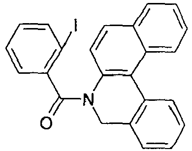

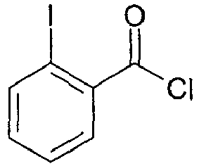

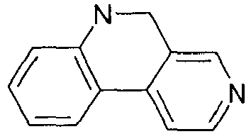


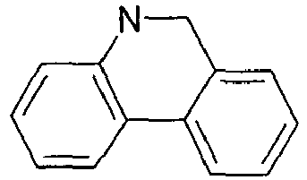


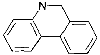


9.7 g (243 mmol) NaH 60%ig in Mineralöl werden in 500 mL Dimethylformamid unter Schutzgasatmosphäre gelöst. 43.9 g (243 mmol) 5,6-Dihydrophenanthridin werden in 500 mL DMF gelöst und zu der Reaktionsmischung zugetropft. Nach 1 h bei Raumtemperatur wird eine Lösung von 60.6 g (242 mmol) 2-Brombenzylbromid in 500 mL DMF zugetropft. Das Reaktionsgemisch wird dann 1 h bei Raumtemperatur gerührt. Nach dieser Zeit wird das Reaktionsgemisch auf Eis gegossen und dreimal mit Dichlormethan extrahiert. Die vereinigten organischen Phasen werden über Na2SO4 getrocknet und eingeengt. Der Rückstand wird mit Toluol heiß extrahiert und aus Toluol / n-Heptan umkristallisiert. Die Ausbeute beträgt 62 g (75 %).9.7 g (243 mmol) of NaH 60% in mineral oil are dissolved in 500 ml of dimethylformamide under a protective gas atmosphere. 43.9 g (243 mmol) of 5,6-dihydrophenanthridine are dissolved in 500 ml of DMF and added dropwise to the reaction mixture. After 1 h at room temperature, a solution of 60.6 g (242 mmol) of 2-bromobenzyl bromide in 500 mL of DMF is added dropwise. The reaction mixture is then stirred for 1 h at room temperature. After this time, the reaction mixture is poured onto ice and extracted three times with dichloromethane. The combined organic phases are dried over Na 2 SO 4 and concentrated. The residue is extracted with hot toluene and recrystallized from toluene / n-heptane. The yield is 62 g (75%).
Analog werden folgende Verbindungen erhalten:


35 g (158 mmol) 5-(2-Brom-benzyl)-5H-phenanthridin-6-on werden in 1000 mL Dimethylformamid unter Schutzgasatmosphäre gelöst. Zu dieser Lösung werden 75.7 g (234 mmol) Tetrabutylammoniumbromid, 2.15 g (9.5 mmol) Palladiumacetat und 10 g (102 mmol) Kaliumacetat zugegeben. Anschließend wird das Gemisch bei 130 °C 2 h gerührt. Nach dieser Zeit wird das Reaktionsgemisch auf Raumtemperatur gekühlt. Der Rückstand wird abgesaugt und mit EtOH gewaschen. Der Rückstand wird aus n-Heptan/Toluol umkristallisiert. Die Ausbeute beträgt 17.7 g (74 %).35 g (158 mmol) of 5- (2-bromo-benzyl) -5H-phenanthridin-6-one are dissolved in 1000 ml of dimethylformamide under a protective gas atmosphere. To this solution are added 75.7 g (234 mmol) of tetrabutylammonium bromide, 2.15 g (9.5 mmol) of palladium acetate and 10 g (102 mmol) of potassium acetate. Subsequently, the mixture is stirred at 130 ° C for 2 h. After this time, the reaction mixture is cooled to room temperature. The residue is filtered off with suction and washed with EtOH. The residue is recrystallized from n-heptane / toluene. The yield is 17.7 g (74%).
Analog werden folgende Verbindungen erhalten:


55.3 g (158 mmol) 5-(2-Brom-benzyl)-5,6-dihydrophenanthridin werden in 500 mL Dimethylformamid unter Schutzgasatmosphäre gelöst. Zu dieser Lösung werden 17.3 g (75 mmol) Benzyltrimethylammoniumbromid und 31.28 g (226 mmol) Kaliumcarbonat werden zugegeben. Anschließend wird unter Schutzgas 5.08 g (22 mmol) Pd(OAC)2 zugegeben, und das Gemisch wird bei 120 °C 9 h gerührt. Nach dieser Zeit wird das Reaktionsgemisch auf Raumtemperatur gekühlt und mit Dichlormethan extrahiert. Die vereinigten organischen Phasen werden über Na2SO4 getrocknet und eingeengt. Der Rückstand wird aus n-Heptan umkristallisiert. Die Ausbeute beträgt 34 g (81 %).55.3 g (158 mmol) of 5- (2-bromo-benzyl) -5,6-dihydrophenanthridine are dissolved in 500 ml of dimethylformamide under a protective gas atmosphere. 17.3 g (75 mmol) of benzyltrimethylammonium bromide and 31.28 g (226 mmol) of potassium carbonate are added to this solution. Subsequently, under protective gas 5.08 g (22 mmol) of Pd (OAC) 2 is added, and the mixture is stirred at 120 ° C for 9 h. After this time, the reaction mixture is cooled to room temperature and extracted with dichloromethane. The combined organic phases are dried over Na 2 SO 4 and concentrated. The residue is recrystallized from n-heptane. The yield is 34 g (81%).
Analog werden folgende Verbindunaen erhalten:


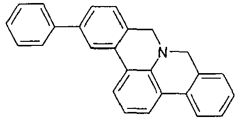

32 g (115 mmol) 9H-8a-Aza-benzo[fg]naphthacen-8-on werden in 1500 mL Aceton gelöst. Zu dieser Lösung werden 54.7 g (346 mmol) Kaliumpermanganat portionsweise werden zugegeben und zwei Tage bei Raumtemperatur gerührt. Nach dieser Zeit wird das restliche Kaliumpermanganat abfiltiert, die Lösung eingeengt und chromatographisch gereinigt (Laufmittel: Heptan/Dichloromethan, 5:1). Der Rückstand wird aus n-Heptan umkristallisiert. Die Ausbeute beträgt 24 g (73 %).32 g (115 mmol) of 9H-8a-aza-benzo [fg] naphthacene-8-one are dissolved in 1500 ml of acetone. To this solution, 54.7 g (346 mmol) of potassium permanganate are added in portions and stirred for two days at room temperature. After this time, the remaining potassium permanganate is filtered off, the solution is concentrated by evaporation and purified by chromatography (eluent: heptane / dichloromethane, 5: 1). The residue is recrystallized from n-heptane. The yield is 24 g (73%).
Analoa werden folgende Verbindungen erhalten:


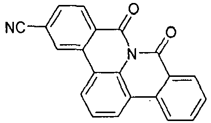


Analog werden folgende Verbindungen mit 6 eg. KMnO4 erhalten:


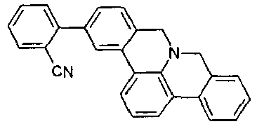


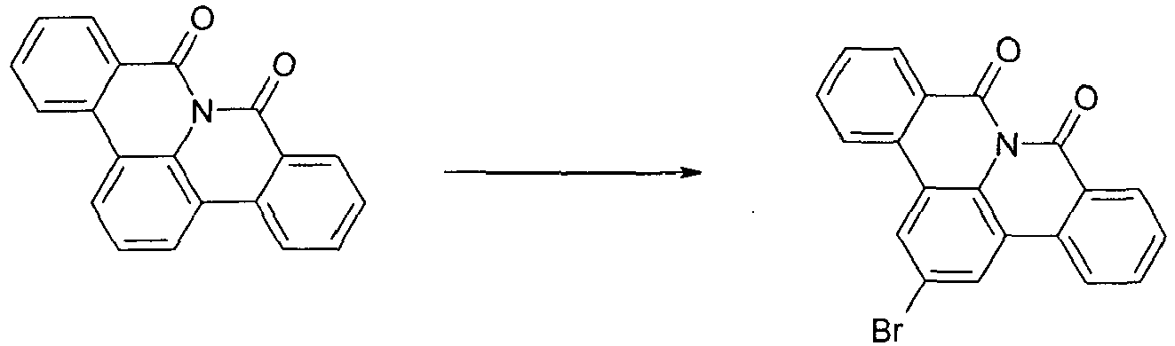
18.6 g (62,5mmol) 8a-Aza-benzo[fg]naphthacen-8,9-dion werden in 1800 mL CH2Cl2 vorgelegt. Anschließend gibt man 25.6 (312 mmol) Natriumacetat und 24.9 g (156 mmol) Brom zur Reaktionsmischung und rührt das Gemisch bei 80 °C für 30 h. Anschließend wird die Mischung mit 150 mL Wasser und 60 g NaOH-Plätzchen versetzt und der ausgefallene Feststoff abgesaugt. Das Produkt wird mit EtOH gewaschen und getrocknet. Ausbeute: 19 g (51 mmol), 81 % d. Th., Reinheit nach 1H-NMR ca. 96 %.18.6 g (62.5 mmol) of 8a-aza-benzo [fg] naphthacene-8,9-dione are initially charged in 1800 ml of CH 2 Cl 2 . Then, 25.6 g (312 mmol) of sodium acetate and 24.9 g (156 mmol) of bromine are added to the reaction mixture, and the mixture is stirred at 80 ° C. for 30 h. Subsequently, the mixture is mixed with 150 ml of water and 60 g of NaOH pellets and the precipitated solid is filtered off with suction. The product is washed with EtOH and dried. Yield: 19 g (51 mmol), 81% of theory. Th., Purity by 1 H-NMR about 96%.
Analoa werden folgende Verbindunaen erhalten:


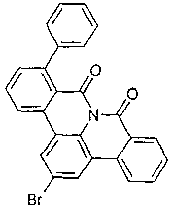


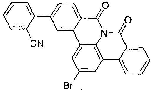


41.3 g (110.0 mmol) 4-dibenzofuranboronsäure, 38 g (110.0 mmol) 2-Brom-8a-aza-benzo[fg]naphthacen-8,9-dion und 44.6 g (210.0 mmol) Trikaliumphosphat werden in 500 mL Toulol, 500 mL Dioxan und 500 mL Wasser suspendiert. Zu dieser Suspension werden 913 mg (3.0 mmol) Trio-tolylphosphin und dann 112 mg (0.5 mmol) Palladium(II)acetat gegeben, und die Reaktionsmischung wird 16 h unter Rückfluss erhitzt. Nach Erkalten wird die organische Phase abgetrennt, über Kieselgel filtriert, dreimal mit 200 mL Wasser gewaschen und anschließend zur Trockene eingeengt. Der Rückstand wird aus Toluol und aus Dichlormethan / isoPropanol umkristallisiert und abschließend im Hochvakuum sublimiert, Reinheit beträgt 99.9 %. Die Ausbeute beträgt 40 g (88 mmol), entsprechend 80% der Theorie.41.3 g (110.0 mmol) of 4-dibenzofuran boronic acid, 38 g (110.0 mmol) of 2-bromo-8a-aza-benzo [fg] naphthacene-8,9-dione and 44.6 g (210.0 mmol) of tripotassium phosphate are dissolved in 500 mL of toluene, 500 mL of dioxane and 500 mL of water. 913 mg (3.0 mmol) of trio-tolylphosphine and then 112 mg (0.5 mmol) of palladium (II) acetate are added to this suspension, and the reaction mixture is heated under reflux for 16 h. After cooling, the organic phase is separated off, filtered through silica gel, washed three times with 200 ml of water and then concentrated to dryness. The residue is recrystallized from toluene and from dichloromethane / isopropanol and finally sublimed under high vacuum, purity is 99.9%. The yield is 40 g (88 mmol), corresponding to 80% of theory.
Analog werden folgende Verbindungen erhalten:


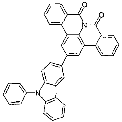


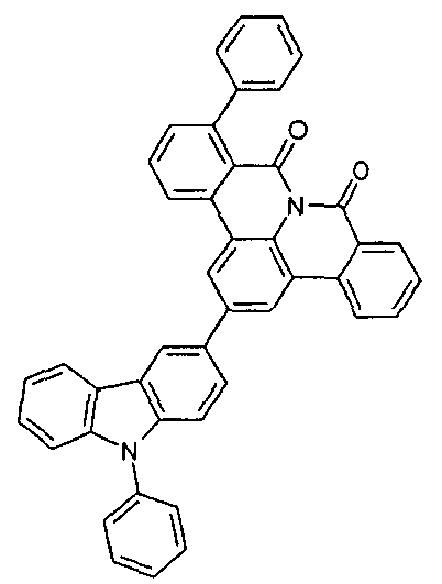


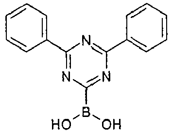


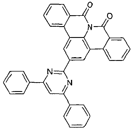


Analog werden folgende Verbindungen mit 0.5 eq. Brom erhalten:


32 g (102-4 mmol) 3,6-Diphenyl-9H-carbazol, 42 g (112 mmol) 2-Brom-8a-aza-benzo[fg]naphthacen-8,9-dion und 2.3 (10-2 mmol)1,3-Di[2-pyridyl]-1,3-propandion, 28.3 g (204 mmol) Kaliumcarbonat und 1.9 g (10.2 mmol) Kupferiodid werden im 1000 ml DMF unter Rückfluss 90 h gerührt. Die Lösung wird mit Wasser verdünnt und mit Essigester zweimal extrahiert, die vereinigten organischen Phasen über Na2SO4 getrocknet und einrotiert und chromatographisch (EtOAc/Hexan: 2/3) gereinigt. Der Rückstand wird aus Toluol und aus Dichlormethan umkristallisiert und abschließend im Hochvakuum sublimiert, Reinheit beträgt 99.9 %. Die Ausbeute beträgt 46 g (75 mmol), entsprechend 68 % der Theorie.32 g (102-4 mmol) of 3,6-diphenyl-9H-carbazole, 42 g (112 mmol) of 2-bromo-8a-aza-benzo [fg] naphthacene-8,9-dione and 2.3 (10-2 mmol ) 1,3-Di [2-pyridyl] -1,3-propanedione, 28.3 g (204 mmol) of potassium carbonate and 1.9 g (10.2 mmol) of copper iodide are stirred in 1000 ml of DMF under reflux for 90 h. The solution is diluted with water and extracted twice with ethyl acetate, the combined organic phases dried over Na 2 SO 4 and concentrated by rotary evaporation and purified by chromatography (EtOAc / hexane: 2/3). The residue is recrystallized from toluene and from dichloromethane and finally sublimed under high vacuum, purity is 99.9%. The yield is 46 g (75 mmol), corresponding to 68% of theory.
Analog werden folgende Verbindungen erhalten:


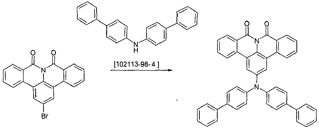
Unter Schutzgas werden 24.5 g (79.8 mmol) Bis-biphenyl-4-yl-amin, 32.7 g (87 mmol) 2-Brom-8a-aza-benzo[fg]naphthacen-8,9-dion, 15.9 ml (15.9 mmol) 1 mol/L Tri-tert-butylphosphin und 1.79 g (7.9 mmol) Palladiumacetat in 120 ml p-Xylol suspendiert. Die Reaktionsmischung wird 16 h unter Rückfluss erhitzt. Nach Erkalten wird die organische Phase abgetrennt, dreimal mit 200 mL Wasser gewaschen und anschließend zur Trockene eingeengt. Der Rückstand wird mit Toluol heiß extrahiert, aus Toluol umkristallisiert und abschließend im Hochvakuum sublimiert. Die Reinheit beträgt 99.9%, Ausbeute 44 g (72 mmol), 83 % der Theorie.Under inert gas, 24.5 g (79.8 mmol) of bis-biphenyl-4-yl-amine, 32.7 g (87 mmol) of 2-bromo-8a-aza-benzo [fg] naphthacene-8,9-dione, 15.9 ml (15.9 mmol ) 1 mol / L tri-tert-butylphosphine and 1.79 g (7.9 mmol) of palladium acetate in 120 ml of p-xylene suspended. The reaction mixture is refluxed for 16 h. After cooling, the organic phase is separated off, washed three times with 200 ml of water and then concentrated to dryness. The residue is extracted with hot toluene, recrystallized from toluene and finally sublimed under high vacuum. The purity is 99.9%, yield 44 g (72 mmol), 83% of theory.
Analog werden folgende Verbindunaen erhalten:


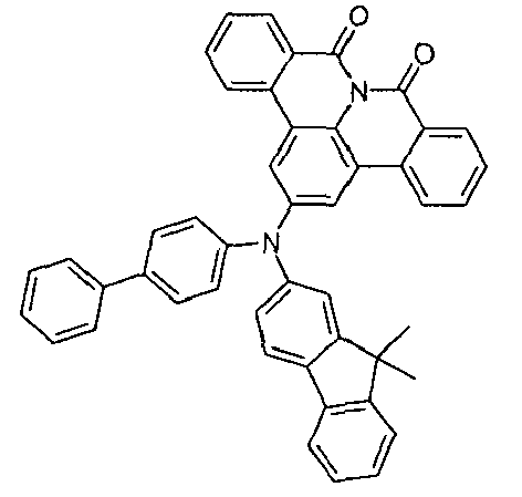


1-Phenyl-1,3-dihydro-benzoimidazol-2-on 52g (250 mmol) und 38 g (275 mmol) K2CO3 werden in 100 ml DMF vorgelegt. Nach 1 h bei Raumtemperatur wird eine Lösung von 62 g (250 mmol) 2-Brombenzylbromid in 500 mL DMF zugetropft. Das Reaktionsgemisch wird dann 25 h bei Raumtemperatur gerührt. Nach dieser Zeit wird das Reaktionsgemisch auf Eis gegossen und dreimal mit Dichlormethan extrahiert. Die vereinigten organischen Phasen werden über Na2SO4 getrocknet und eingeengt. Der Rückstand wird mit Toluol heiß extrahiert und aus Toluol / n-Heptan umkristallisiert. Die Ausbeute beträgt 65 g (70 %).1-Phenyl-1,3-dihydro-benzoimidazol-2-one 52g (250 mmol) and 38 g (275 mmol) K 2 CO 3 are placed in 100 ml of DMF. After 1 h at room temperature, a solution of 62 g (250 mmol) of 2-bromobenzyl bromide in 500 mL of DMF is added dropwise. The reaction mixture is then stirred for 25 h at room temperature. After this time, the reaction mixture is poured onto ice and extracted three times with dichloromethane. The combined organic phases are dried over Na 2 SO 4 and concentrated. The residue is extracted with hot toluene and recrystallized from toluene / n-heptane. The yield is 65 g (70%).
Analog werden folgende Verbindungen erhalten:
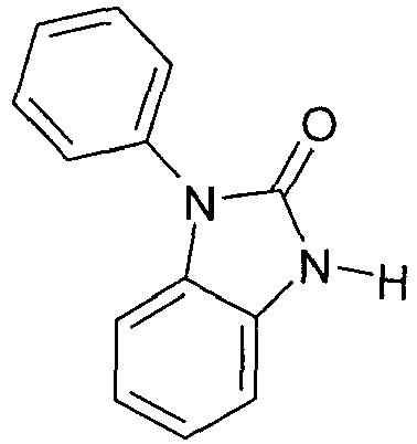


Analog werden folgende Verbindungen mit 125 mmol 1,3-Dihydro-2H-benzimidazol-2-on [615-16-7] erhalten:


Die Cyclisierung erfolgt analog Beispiel 5:


Die Weiteroxidation erfolgt analog Beispiel 6:


Die Bromierung erfolgt analog Beispiel 7:


Über Ullmann-Reaktion analog zu Beispiel 9 werden folgende Verbindungen hergestellt:


In den folgenden Beispielen E1 bis E27 (siehe Tabellen 1 und 2) werden die Daten verschiedener OLEDs vorgestellt. Glasplättchen, die mit strukturiertem ITO (Indium Zinn Oxid) der Dicke 50 nm beschichtet sind werden zur verbesserten Prozessierung mit 20 nm PEDOT:PSS beschichtet (Poly(3,4-ethylenedioxythiophen)poly(styrolsulfonat), bezogen als CLEVIOS™ P VP AI 4083 von Heraeus Precious Metals GmbH Deutschland, aus wässriger Lösung aufgeschleudert). Diese beschichteten Glasplättchen bilden die Substrate, auf welche die OLEDs aufgebracht werden. Die OLEDs haben prinzipiell folgenden Schichtaufbau: Substrat / Lochtransportschicht (HTL) / Zwischenschicht (IL) / Elektronenblockierschicht (EBL) / Emissionsschicht (EML) / optionale Lochblockierschicht (HBL) / Elektronentransportschicht (ETL) / optionale Elektroneninjektionsschicht (EIL) und abschließend eine Kathode. Die Kathode wird durch eine 100 nm dicke Aluminiumschicht gebildet. Der genaue Aufbau der OLEDs ist Tabelle 1 zu entnehmen. Die zur Herstellung der OLEDs benötigten Materialien sind in Tabelle 3 gezeigt. Eine Bezeichnung wie "8a" bezieht sich hierbei auf die entsprechende Verbindung aus dem oben genannten Beispiel 8a. Dies gilt analog für alle verwendeten erfindungsgemäßen Materialien.In the following examples E1 to E27 (see Tables 1 and 2) the data of different OLEDs are presented. Glass plates coated with structured 50 μm thick ITO (Indium Tin Oxide) are coated with 20 nm PEDOT: PSS for improved processing (poly (3,4-ethylenedioxythiophene) poly (styrenesulfonate) available as CLEVIOS ™ P VP AI 4083 from Heraeus Precious Metals GmbH Germany, spin-on from aqueous solution). These coated glass plates form the substrates to which the OLEDs are applied. In principle, the OLEDs have the following layer structure: substrate / hole transport layer (HTL) / intermediate layer (IL) / electron blocking layer (EBL) / emission layer (EML) / optional hole blocking layer (HBL) / electron transport layer (ETL) / optional electron injection layer (EIL) and finally a cathode. The cathode is formed by a 100 nm thick aluminum layer. The exact structure of the OLEDs is shown in Table 1. The materials needed to make the OLEDs are shown in Table 3. A term such as "8a" refers to the corresponding compound from the above Example 8a. This applies analogously to all materials used according to the invention.
Alle Materialien werden in einer Vakuumkammer thermisch aufgedampft. Dabei besteht die Emissionsschicht immer aus mindestens einem Matrixmaterial (Hostmaterial, Wirtsmaterial) und einem emittierenden Dotierstoff (Dotand, Emitter), der dem Matrixmaterial bzw. den Matrixmaterialien durch Coverdampfung in einem bestimmten Volumenanteil beigemischt wird. Eine Angabe wie IC1:8c:TER1 (55%:35%:10%) bedeutet hierbei, dass das Material IC1 in einem Volumenanteil von 55%, 8c in einem Anteil von 35% und TER1 in einem Anteil von 10% in der Schicht vorliegt. Analog kann auch die Elektronentransportschicht aus einer Mischung von zwei Materialien bestehen.All materials are thermally evaporated in a vacuum chamber. In this case, the emission layer always consists of at least one matrix material (host material, host material) and an emitting dopant (dopant, emitter), which is admixed to the matrix material or the matrix materials by co-evaporation in a specific volume fraction. An indication such as IC1: 8c: TER1 (55%: 35%: 10%) here means that the material IC1 in a volume fraction of 55%, 8c in a proportion of 35% and TER1 in a proportion of 10% in the layer is present. Similarly, the electron transport layer may consist of a mixture of two materials.
Die OLEDs werden standardmäßig charakterisiert. Hierfür werden die Elektrolumineszenzspektren, die Stromeffizienz (gemessen in cd/A), die Leistungseffizienz (gemessen in lm/W) und die externe Quanteneffizienz (EQE, gemessen in Prozent) in Abhängigkeit der Leuchtdichte, berechnet aus Strom-Spannungs-Leuchtdichte-Kennlinien (IUL-Kennlinien) unter Annahme einer lambertschen Abstrahlcharakteristik sowie die Lebensdauer bestimmt. Die Elektrolumineszenzspektren werden bei einer Leuchtdichte von 1000 cd/m2 bestimmt und daraus die CIE 1931 x und y Farbkoordinaten berechnet. Die Angabe U1000 in Tabelle 2 bezeichnet die Spannung, die für eine Leuchtdichte von 1000 cd/m2 benötigt wird. SE1000 und LE1000 bezeichnen die Strom- bzw. Leistungseffizienz, die bei 1000 cd/m2 erreicht werden. EQE1000 schließlich bezeichnet die externe Quanteneffizienz bei einer Betriebsleuchtdichte von 1000 cd/m2. Als Lebensdauer LD wird die Zeit definiert, nach der die Leuchtdichte bei Betrieb mit konstantem Strom von der Startleuchtdichte auf einen gewissen Anteil L1 absinkt. Eine Angabe von L0;j0 = 4000 cd/m2 und L1 = 80% in Tabelle 2 bedeutet, dass die in Spalte LD angegebene Lebensdauer der Zeit entspricht, nach der die Anfangsleuchtdichte von 4000 cd/m2 auf 3200 cd/m2 absinkt. Analog bedeutet L0;j0 = 20 mA/cm2, L1 = 70%, dass die Leuchtdichte bei Betrieb mit 20 mA/cm2 nach der Zeit LD auf 70% ihres Anfangswertes absinkt.The OLEDs are characterized by default. For this purpose, the electroluminescence spectra, the current efficiency (measured in cd / A), the power efficiency (measured in lm / W) and the external quantum efficiency (EQE, measured in percent) as a function of the luminance, calculated from current-voltage-luminance characteristics ( IUL characteristics) assuming a Lambertian radiation characteristic and the lifetime determined. The electroluminescence spectra are determined at a luminance of 1000 cd / m 2 and from this the CIE 1931 x and y color coordinates are calculated. The indication U1000 in Table 2 indicates the voltage required for a luminance of 1000 cd / m 2 . SE1000 and LE1000 indicate the power efficiency achieved at 1000 cd / m 2 . Finally, EQE1000 refers to external quantum efficiency at an operating luminance of 1000 cd / m 2 . The lifetime LD is defined as the time after which the luminance decreases from the start luminance to a certain proportion L1 when operating with a constant current. An indication of L0; j0 = 4000 cd / m = 2 and L1 80% in Table 2 that the specified in column LD life corresponds to the time after which the initial luminance of 4000 cd / m 2 to 3200 cd / m 2 drops , Analogously, L0; j0 = 20 mA / cm 2, L1 = 70%, the luminance decreases when operating at 20 mA / cm 2 after the time LD to 70% of its initial value.
Die Daten der verschiedenen OLEDs sind in Tabelle 2 zusammengefasst. Man erhält bei Einsatz der erfindungsgemäßen Verbindungen sowohl bei Verwendung als Elektronentransportmaterial (Beispiele E1, E2, E13, E17, E18) als auch Matrixmaterial für phopshoreszierende Emitter (restliche Beispiele) sehr gute Werte für Effizienz, Spannung und Lebensdauer. Dies gilt beim Einsatz als Einzelmatrix sowie in Mixed-Matrix Systemen in Kombination mit unterschiedlichen Materialien wie IC1, IC2, Cbz1. Insbesondere sind die hervorragenden Spannungen und damit Leistungseffizienzen bei gleichtzeitig sehr guter Lebensdauer hervorzuheben (siehe z. B. E10).


Claims (14)
- Compound of the formula (1),
 X is on each occurrence, identically or differently, CR or N; or two adjacent groups X together stand for a group selected from NR, O or S, resulting in the formation of a five-membered ring;Y is on each occurrence, identically or differently, Z=Z, O, S or NR, where R is not equal to H;Z is on each occurrence, identically or differently, CR or N or the adjacent groups Z=Z together stand for a group of the formula (2),
 L is not present for n = 1 and is a single bond or a divalent group for n = 2 and a trivalent group for n = 3 and a tetravalent group for n = 4 and a pentavalent group for n = 5 and a hexavalent group for n = 6; L here is bonded at any desired point of the basic structure instead of a group R;R is selected on each occurrence, identically or differently, from the group consisting of H, D, F, Cl, Br, I, CN, NO2, N(Ar1)2, N(R1)2, C(=O)Ar1, C(=O)R1, P(=O)(Ar1)2, a straight-chain alkyl, alkoxy or thioalkyl group having 1 to 40 C atoms or a branched or cyclic alkyl, alkoxy or thioalkyl group having 3 to 40 C atoms or an alkenyl or alkynyl group having 2 to 40 C atoms, each of which may be substituted by one or more radicals R1, where one or more non-adjacent CH2 groups may be replaced by R1C=CR1, C=C, Si(R1)2, C=O, C=S, C=NR1, P(=O)(R1), SO, SO2, NR1, O, S or CONR1 and where one or more H atoms may be replaced by D, F, Cl, Br, I, CN or NO2, an aromatic or heteroaromatic ring system having 5 to 60 aromatic ring atoms, which may in each case be substituted by one or more radicals R1, an aryloxy or heteroaryloxy group having 5 to 60 aromatic ring atoms, which may be substituted by one or more radicals R1, an aralkyl or heteroaralkyl group having 5 to 60 aromatic ring atoms, which may be substituted by one or more radicals R1, or a combination of these systems, where two or more adjacent substituents R may optionally form a monocyclic or polycyclic, aliphatic, aromatic or heteroaromatic ring system, which may be substituted by one or more radicals R1;Ar1 is on each occurrence, identically or differently, an aromatic or heteroaromatic ring system having 5-30 aromatic ring atoms, which may be substituted by one or more non-aromatic radicals R1; two radicals Ar1 here which are bonded to the same N atom or P atom may also be bridged to one another by a single bond or a bridge selected from N(R1), C(R1)2 or O;R1 is selected from the group consisting of H, D, F, CN, an aliphatic hydrocarbon radical having 1 to 20 C atoms, an aromatic or heteroaromatic ring system having 5 to 30 aromatic ring atoms, in which one or more H atoms may be replaced by D, F, Cl, Br, I, CN or an alkyl group having 1 to 10 C atoms or an alkenyl group having 2 to 10 C atoms, where two or more adjacent substituents R1 may form a mono- or polycyclic, aliphatic, aromatic or hetero-aromatic ring system with one another;n is 1, 2, 3, 4, 5 or 6;where the following compound is excluded from the invention:
- Compound according to Claim 1, selected from the compounds of the formula (5) and formula (9),

- Compound according to Claim 1 or 2, selected from the compounds of the formula (6),

- Compound according to one or more of Claims 1 to 3, selected from the compounds of the formulae (7), (8), (10) and (11),


- Compound according to one or more of Claims 1 to 4, selected from the compounds of the formulae (7a), (8a), (10a) and (11a),


- Compound according to one or more of Claims 1 to 5, selected from the compounds of the formulae (7c), (8c), (10c) and (11c),


- Compound according to one or more of Claims 1 to 3, selected from the compounds of the formula (12),

- Compound according to one or more of Claims 1 to 7, characterised in that L, for n = 2, is selected from a single bond, CR2, O, NR or C(=O) or, for n = 3, stands for N or, for n ≥ 2, is selected from an aromatic or heteroaromatic ring system having 5 to 24 aromatic ring atoms, which may be substituted by one or more radicals R.
- Compound according to one or more of Claims 1 to 8, characterised in that at least one radical R is selected from the group consisting of an aromatic or heteroaromatic ring system having 5 to 24 aromatic ring atoms, which may be substituted by one or more radicals R1, and/or in that at least one radical R is selected from -C(=O)Ar1 or -P(=O)(Ar1)2 and/or in that at least one radical R is selected from triaryl- or heteroarylamine derivatives and/or at least one substituent R stands for -N(Ar1)2
- Compound according to one or more of Claims 1 to 9, characterised in that at least one group R is selected from the group consisting of benzene, biphenyl, terphenyl, quaterphenyl, fluorene, spirobifluorene, naphthalene, pyrrole, furan, thiophene, indole, benzofuran, benzothiophene, carbazole, dibenzothiophene, dibenzofuran, 1,3,5-triazine, pyridine, pyrimidine, pyrazine, pyridazine, indenocarbazole, bridged carbazole, indolocarbazole, anthracene, phenanthrene, pyrene, triphenylene, benzanthracene, quinoline, isoquinoline, phenanthridine, phenanthroline, azacarbazole, imidazole, pyrazole, thiazole, oxazole, oxadiazole, triazole, benzimidazole or combinations of two, three or four of these groups, where the groups may each be substituted by one or more radicals R1.
- Formulation comprising at least one compound according to one or more of Claims 1 to 10 and at least one further compound, in particular an organic solvent.
- Use of a compound according to one or more of Claims 1 to 10 in an electronic device.
- Electronic device comprising at least one compound according to one or more of Claims 1 to 10, in particular selected from the group consisting of organic electroluminescent devices, organic integrated circuits, organic field-effect transistors, organic thin-film transistors, organic light-emitting transistors, organic solar cells, organic dye-sensitised solar cells, organic optical detectors, organic photoreceptors, organic field-quench devices, light-emitting electrochemical cells, organic laser diodes and organic plasmon emitting devices.
- Electronic device according to Claim 13, which is an organic electroluminescent device, characterised in that the compound according to one or more of Claims 1 to 10 is employed as matrix material for a fluorescent or phosphorescent emitter and/or in a hole-blocking layer and/or in an electron-transport layer.
Priority Applications (1)
| Application Number | Priority Date | Filing Date | Title |
|---|---|---|---|
| EP13762409.4A EP2906661B1 (en) | 2012-10-11 | 2013-09-13 | Materials for organic electroluminescent devices |
Applications Claiming Priority (3)
| Application Number | Priority Date | Filing Date | Title |
|---|---|---|---|
| EP12007040 | 2012-10-11 | ||
| EP13762409.4A EP2906661B1 (en) | 2012-10-11 | 2013-09-13 | Materials for organic electroluminescent devices |
| PCT/EP2013/002748 WO2014056567A1 (en) | 2012-10-11 | 2013-09-13 | Materials for organic electroluminescent devices |
Publications (2)
| Publication Number | Publication Date |
|---|---|
| EP2906661A1 EP2906661A1 (en) | 2015-08-19 |
| EP2906661B1 true EP2906661B1 (en) | 2016-10-26 |
Family
ID=47076015
Family Applications (1)
| Application Number | Title | Priority Date | Filing Date |
|---|---|---|---|
| EP13762409.4A Active EP2906661B1 (en) | 2012-10-11 | 2013-09-13 | Materials for organic electroluminescent devices |
Country Status (4)
| Country | Link |
|---|---|
| US (1) | US9741942B2 (en) |
| EP (1) | EP2906661B1 (en) |
| JP (1) | JP6250684B2 (en) |
| WO (1) | WO2014056567A1 (en) |
Cited By (1)
| Publication number | Priority date | Publication date | Assignee | Title |
|---|---|---|---|---|
| CN107216331A (en) * | 2017-07-07 | 2017-09-29 | 华南理工大学 | A kind of Tetrahydronaphthyridderivates and tetrahydro quinazoline derivative and its synthetic method and application |
Families Citing this family (12)
| Publication number | Priority date | Publication date | Assignee | Title |
|---|---|---|---|---|
| WO2016012075A1 (en) | 2014-07-21 | 2016-01-28 | Merck Patent Gmbh | Materials for electronic devices |
| CN107001334A (en) | 2014-12-12 | 2017-08-01 | 默克专利有限公司 | Organic compound with soluble groups |
| KR102554987B1 (en) | 2015-02-03 | 2023-07-12 | 메르크 파텐트 게엠베하 | Metal complexes |
| US10249831B2 (en) | 2015-02-09 | 2019-04-02 | Merck Patent Gmbh | Electronic device containing cyclic lactams |
| US10074815B2 (en) * | 2015-03-31 | 2018-09-11 | The Regents Of The University Of Michigan | Organic electroluminescent devices |
| US11345687B2 (en) | 2016-11-09 | 2022-05-31 | Merck Patent Gmbh | Materials for organic electroluminescent devices |
| CN109996788B (en) * | 2016-11-30 | 2023-11-17 | 默克专利有限公司 | Compounds having valerolactam structure |
| US11466021B2 (en) | 2016-12-05 | 2022-10-11 | Merck Patent Gmbh | Materials for organic electroluminescent devices |
| US11034702B2 (en) | 2016-12-06 | 2021-06-15 | Valorbec, Société en commandite | Thienoisoquinolines and their derivatives for the treatment of cancer |
| TWI791481B (en) * | 2017-01-30 | 2023-02-11 | 德商麥克專利有限公司 | Method for forming an organic electroluminescence (el) element |
| US20220013730A1 (en) * | 2018-11-30 | 2022-01-13 | Merck Patent Gmbh | Compounds for electronic devices |
| WO2021053046A1 (en) * | 2019-09-20 | 2021-03-25 | Merck Patent Gmbh | Peri-condensed heterocyclic compounds as materials for electronic devices |
Family Cites Families (53)
| Publication number | Priority date | Publication date | Assignee | Title |
|---|---|---|---|---|
| IE49377B1 (en) * | 1979-02-01 | 1985-10-02 | Lilly Co Eli | Process for preparation of beta-lactam compounds |
| EP0074777B1 (en) * | 1981-09-09 | 1987-10-14 | Pfizer Inc. | Antibacterial 6-(2-amino-2-(4-acyloxy-phenyl) acetamido) penicillanoyloxymethyl esters |
| US4539507A (en) | 1983-03-25 | 1985-09-03 | Eastman Kodak Company | Organic electroluminescent devices having improved power conversion efficiencies |
| US5151629A (en) | 1991-08-01 | 1992-09-29 | Eastman Kodak Company | Blue emitting internal junction organic electroluminescent device (I) |
| JPH07133483A (en) | 1993-11-09 | 1995-05-23 | Shinko Electric Ind Co Ltd | Organic luminescent material for el element and el element |
| EP0676461B1 (en) | 1994-04-07 | 2002-08-14 | Covion Organic Semiconductors GmbH | Spiro compounds and their application as electroluminescence materials |
| DE19652261A1 (en) | 1996-12-16 | 1998-06-18 | Hoechst Ag | Aryl-substituted poly (p-arylenevinylenes), process for their preparation and their use in electroluminescent devices |
| TW591030B (en) * | 1997-03-10 | 2004-06-11 | Janssen Pharmaceutica Nv | Farnesyl transferase inhibiting 1,8-annelated quinolinone derivatives substituted with N- or C-linked imidazoles |
| EP2306495B1 (en) | 1999-05-13 | 2017-04-19 | The Trustees of Princeton University | Very high efficiency organic light emitting devices based on electrophosphorescence |
| KR100840637B1 (en) | 1999-12-01 | 2008-06-24 | 더 트러스티즈 오브 프린스턴 유니버시티 | Complexes of form l2mx as phosphorescent dopants for organic leds |
| TW532048B (en) | 2000-03-27 | 2003-05-11 | Idemitsu Kosan Co | Organic electroluminescence element |
| US20020121638A1 (en) | 2000-06-30 | 2002-09-05 | Vladimir Grushin | Electroluminescent iridium compounds with fluorinated phenylpyridines, phenylpyrimidines, and phenylquinolines and devices made with such compounds |
| AU2001283274A1 (en) | 2000-08-11 | 2002-02-25 | The Trustees Of Princeton University | Organometallic compounds and emission-shifting organic electrophosphorescence |
| JP4154139B2 (en) | 2000-09-26 | 2008-09-24 | キヤノン株式会社 | Light emitting element |
| JP4154138B2 (en) | 2000-09-26 | 2008-09-24 | キヤノン株式会社 | Light emitting element, display device and metal coordination compound |
| JP4154140B2 (en) | 2000-09-26 | 2008-09-24 | キヤノン株式会社 | Metal coordination compounds |
| ITRM20020411A1 (en) | 2002-08-01 | 2004-02-02 | Univ Roma La Sapienza | SPIROBIFLUORENE DERIVATIVES, THEIR PREPARATION AND USE. |
| JP4411851B2 (en) | 2003-03-19 | 2010-02-10 | コニカミノルタホールディングス株式会社 | Organic electroluminescence device |
| WO2004093207A2 (en) | 2003-04-15 | 2004-10-28 | Covion Organic Semiconductors Gmbh | Mixtures of matrix materials and organic semiconductors capable of emission, use of the same and electronic components containing said mixtures |
| EP2236579B1 (en) | 2003-04-23 | 2014-04-09 | Konica Minolta Holdings, Inc. | Organic electroluminescent element and display |
| DE10333232A1 (en) | 2003-07-21 | 2007-10-11 | Merck Patent Gmbh | Organic electroluminescent element |
| DE10338550A1 (en) | 2003-08-19 | 2005-03-31 | Basf Ag | Transition metal complexes with carbene ligands as emitters for organic light-emitting diodes (OLEDs) |
| DE10345572A1 (en) | 2003-09-29 | 2005-05-19 | Covion Organic Semiconductors Gmbh | metal complexes |
| US7795801B2 (en) | 2003-09-30 | 2010-09-14 | Konica Minolta Holdings, Inc. | Organic electroluminescent element, illuminator, display and compound |
| CN100536190C (en) | 2003-11-25 | 2009-09-02 | 默克专利有限公司 | Organic electroluminescent element |
| US7790890B2 (en) | 2004-03-31 | 2010-09-07 | Konica Minolta Holdings, Inc. | Organic electroluminescence element material, organic electroluminescence element, display device and illumination device |
| DE102004023277A1 (en) | 2004-05-11 | 2005-12-01 | Covion Organic Semiconductors Gmbh | New material mixtures for electroluminescence |
| US7598388B2 (en) | 2004-05-18 | 2009-10-06 | The University Of Southern California | Carbene containing metal complexes as OLEDs |
| JP4862248B2 (en) | 2004-06-04 | 2012-01-25 | コニカミノルタホールディングス株式会社 | Organic electroluminescence element, lighting device and display device |
| ITRM20040352A1 (en) | 2004-07-15 | 2004-10-15 | Univ Roma La Sapienza | OLIGOMERIC DERIVATIVES OF SPIROBIFLUORENE, THEIR PREPARATION AND THEIR USE. |
| CN101171320B (en) | 2005-05-03 | 2013-04-10 | 默克专利有限公司 | Organic electroluminescent device |
| DE102005037115A1 (en) * | 2005-08-03 | 2007-02-08 | Basf Ag | polychromophores |
| CN101321755B (en) | 2005-12-01 | 2012-04-18 | 新日铁化学株式会社 | Compound for organic electroluminescent element and organic electroluminescent element |
| DE102006025777A1 (en) | 2006-05-31 | 2007-12-06 | Merck Patent Gmbh | New materials for organic electroluminescent devices |
| KR100955993B1 (en) | 2006-11-09 | 2010-05-04 | 신닛테츠가가쿠 가부시키가이샤 | Compound for organic electroluminescent device and organic electroluminescent device |
| US8866377B2 (en) | 2006-12-28 | 2014-10-21 | Universal Display Corporation | Long lifetime phosphorescent organic light emitting device (OLED) structures |
| DE102007002714A1 (en) | 2007-01-18 | 2008-07-31 | Merck Patent Gmbh | New materials for organic electroluminescent devices |
| DE102007053771A1 (en) | 2007-11-12 | 2009-05-14 | Merck Patent Gmbh | Organic electroluminescent devices |
| US7862908B2 (en) | 2007-11-26 | 2011-01-04 | National Tsing Hua University | Conjugated compounds containing hydroindoloacridine structural elements, and their use |
| DE102008033943A1 (en) | 2008-07-18 | 2010-01-21 | Merck Patent Gmbh | New materials for organic electroluminescent devices |
| DE102008036982A1 (en) | 2008-08-08 | 2010-02-11 | Merck Patent Gmbh | Organic electroluminescent device |
| KR101506919B1 (en) | 2008-10-31 | 2015-03-30 | 롬엔드하스전자재료코리아유한회사 | Novel compounds for organic electronic material and organic electronic device using the same |
| DE102008056688A1 (en) | 2008-11-11 | 2010-05-12 | Merck Patent Gmbh | Materials for organic electroluminescent devices |
| EP2344607B1 (en) | 2008-11-11 | 2013-04-10 | Merck Patent GmbH | Organic electroluminescent devices |
| DE102009023155A1 (en) | 2009-05-29 | 2010-12-02 | Merck Patent Gmbh | Materials for organic electroluminescent devices |
| DE102009031021A1 (en) | 2009-06-30 | 2011-01-05 | Merck Patent Gmbh | Materials for organic electroluminescent devices |
| DE102009048791A1 (en) | 2009-10-08 | 2011-04-14 | Merck Patent Gmbh | Materials for organic electroluminescent devices |
| DE102010005697A1 (en) | 2010-01-25 | 2011-07-28 | Merck Patent GmbH, 64293 | Connections for electronic devices |
| DE102010012738A1 (en) | 2010-03-25 | 2011-09-29 | Merck Patent Gmbh | Materials for organic electroluminescent devices |
| DE102010019306B4 (en) | 2010-05-04 | 2021-05-20 | Merck Patent Gmbh | Organic electroluminescent devices |
| DE102010048608A1 (en) | 2010-10-15 | 2012-04-19 | Merck Patent Gmbh | Materials for organic electroluminescent devices |
| CN103492383B (en) | 2011-04-18 | 2017-05-10 | 默克专利有限公司 | Materials for organic electroluminescent devices |
| CA2849087A1 (en) | 2011-09-21 | 2013-03-28 | Merck Patent Gmbh | Carbazole derivatives for organic electroluminescent devices |
-
2013
- 2013-09-13 JP JP2015536005A patent/JP6250684B2/en active Active
- 2013-09-13 US US14/434,460 patent/US9741942B2/en active Active
- 2013-09-13 EP EP13762409.4A patent/EP2906661B1/en active Active
- 2013-09-13 WO PCT/EP2013/002748 patent/WO2014056567A1/en active Application Filing
Cited By (2)
| Publication number | Priority date | Publication date | Assignee | Title |
|---|---|---|---|---|
| CN107216331A (en) * | 2017-07-07 | 2017-09-29 | 华南理工大学 | A kind of Tetrahydronaphthyridderivates and tetrahydro quinazoline derivative and its synthetic method and application |
| CN107216331B (en) * | 2017-07-07 | 2019-06-18 | 华南理工大学 | A kind of Tetrahydronaphthyridderivates simultaneously tetrahydro quinazoline derivative and its synthetic method and application |
Also Published As
| Publication number | Publication date |
|---|---|
| US9741942B2 (en) | 2017-08-22 |
| WO2014056567A1 (en) | 2014-04-17 |
| US20150270495A1 (en) | 2015-09-24 |
| JP6250684B2 (en) | 2017-12-20 |
| JP2016500675A (en) | 2016-01-14 |
| EP2906661A1 (en) | 2015-08-19 |
Similar Documents
| Publication | Publication Date | Title |
|---|---|---|
| EP3180411B1 (en) | Materials for organic electroluminescent devices | |
| EP2773721B1 (en) | Organic electroluminescent device | |
| EP2906661B1 (en) | Materials for organic electroluminescent devices | |
| EP2883422B1 (en) | Materials for organic electroluminescence devices | |
| EP3027707B1 (en) | Materials for electronic devices | |
| EP2486036B1 (en) | Materials for organic electroluminescent devices | |
| EP3573985B1 (en) | Materials for organic electroluminescent devices | |
| EP2768808B1 (en) | Materials for organic electroluminescent devices | |
| EP2699571B1 (en) | Materials for organic electroluminescent devices | |
| EP3027708B1 (en) | Materials for electronic devices | |
| DE112011103904B4 (en) | Materials for organic electroluminescent devices | |
| EP2758372B1 (en) | Carbazole derivatives for organic electroluminescent devices | |
| EP2714841B1 (en) | Organic electroluminescence device | |
| EP2828266B1 (en) | 9,9'-spiro-bixanthene derivatives for electroluminescent devices | |
| EP3107977B1 (en) | Materials for organic electroluminescent devices | |
| EP3160954B1 (en) | Materials for organic electroluminescent devices | |
| EP3016952B1 (en) | Spiro-condensed lactam compounds for organic electroluminescent devices | |
| EP3094703B1 (en) | Materials for organic electroluminescent devices | |
| EP3110796B1 (en) | Materials for organic light-emitting devices | |
| DE102010019306A1 (en) | Organic electroluminescent devices | |
| EP2794619B1 (en) | Compounds for organic electroluminescent devices | |
| EP3681890B1 (en) | Materials for organic electroluminescent devices | |
| EP3257093B1 (en) | Electronic device containing cyclic lactams | |
| WO2011157346A1 (en) | Compounds for electronic devices | |
| EP3744155B1 (en) | Materials for organic electroluminescent devices |
Legal Events
| Date | Code | Title | Description |
|---|---|---|---|
| PUAI | Public reference made under article 153(3) epc to a published international application that has entered the european phase |
Free format text: ORIGINAL CODE: 0009012 |
|
| 17P | Request for examination filed |
Effective date: 20150224 |
|
| AK | Designated contracting states |
Kind code of ref document: A1 Designated state(s): AL AT BE BG CH CY CZ DE DK EE ES FI FR GB GR HR HU IE IS IT LI LT LU LV MC MK MT NL NO PL PT RO RS SE SI SK SM TR |
|
| AX | Request for extension of the european patent |
Extension state: BA ME |
|
| RIN1 | Information on inventor provided before grant (corrected) |
Inventor name: KROEBER, JONAS VALENTIN Inventor name: PFLUMM, CHRISTOF Inventor name: PARHAM, AMIR HOSSAIN Inventor name: JATSCH, ANJA Inventor name: STOESSEL, PHILIPP Inventor name: EBERLE, THOMAS |
|
| RIN1 | Information on inventor provided before grant (corrected) |
Inventor name: PFLUMM, CHRISTOF Inventor name: KROEBER, JONAS VALENTIN Inventor name: PARHAM, AMIR HOSSAIN Inventor name: STOESSEL, PHILIPP Inventor name: JATSCH, ANJA Inventor name: EBERLE, THOMAS |
|
| DAX | Request for extension of the european patent (deleted) | ||
| GRAP | Despatch of communication of intention to grant a patent |
Free format text: ORIGINAL CODE: EPIDOSNIGR1 |
|
| RIC1 | Information provided on ipc code assigned before grant |
Ipc: H01L 51/52 20060101ALI20160526BHEP Ipc: C07D 471/22 20060101ALI20160526BHEP Ipc: C07D 498/14 20060101ALI20160526BHEP Ipc: H01L 51/00 20060101ALI20160526BHEP Ipc: H01L 51/50 20060101ALI20160526BHEP Ipc: C07D 495/22 20060101ALI20160526BHEP Ipc: C07D 491/048 20060101ALI20160526BHEP Ipc: C07D 455/03 20060101ALI20160526BHEP Ipc: C07D 513/14 20060101ALI20160526BHEP Ipc: C09K 11/02 20060101ALI20160526BHEP Ipc: C09K 11/06 20060101AFI20160526BHEP Ipc: C07D 471/16 20060101ALI20160526BHEP |
|
| INTG | Intention to grant announced |
Effective date: 20160613 |
|
| GRAS | Grant fee paid |
Free format text: ORIGINAL CODE: EPIDOSNIGR3 |
|
| GRAA | (expected) grant |
Free format text: ORIGINAL CODE: 0009210 |
|
| AK | Designated contracting states |
Kind code of ref document: B1 Designated state(s): AL AT BE BG CH CY CZ DE DK EE ES FI FR GB GR HR HU IE IS IT LI LT LU LV MC MK MT NL NO PL PT RO RS SE SI SK SM TR |
|
| REG | Reference to a national code |
Ref country code: GB Ref legal event code: FG4D Free format text: NOT ENGLISH |
|
| REG | Reference to a national code |
Ref country code: CH Ref legal event code: EP |
|
| REG | Reference to a national code |
Ref country code: AT Ref legal event code: REF Ref document number: 840035 Country of ref document: AT Kind code of ref document: T Effective date: 20161115 |
|
| REG | Reference to a national code |
Ref country code: IE Ref legal event code: FG4D Free format text: LANGUAGE OF EP DOCUMENT: GERMAN |
|
| REG | Reference to a national code |
Ref country code: DE Ref legal event code: R096 Ref document number: 502013005122 Country of ref document: DE |
|
| REG | Reference to a national code |
Ref country code: LT Ref legal event code: MG4D |
|
| PG25 | Lapsed in a contracting state [announced via postgrant information from national office to epo] |
Ref country code: LV Free format text: LAPSE BECAUSE OF FAILURE TO SUBMIT A TRANSLATION OF THE DESCRIPTION OR TO PAY THE FEE WITHIN THE PRESCRIBED TIME-LIMIT Effective date: 20161026 |
|
| REG | Reference to a national code |
Ref country code: NL Ref legal event code: MP Effective date: 20161026 |
|
| PG25 | Lapsed in a contracting state [announced via postgrant information from national office to epo] |
Ref country code: NO Free format text: LAPSE BECAUSE OF FAILURE TO SUBMIT A TRANSLATION OF THE DESCRIPTION OR TO PAY THE FEE WITHIN THE PRESCRIBED TIME-LIMIT Effective date: 20170126 Ref country code: SE Free format text: LAPSE BECAUSE OF FAILURE TO SUBMIT A TRANSLATION OF THE DESCRIPTION OR TO PAY THE FEE WITHIN THE PRESCRIBED TIME-LIMIT Effective date: 20161026 Ref country code: LT Free format text: LAPSE BECAUSE OF FAILURE TO SUBMIT A TRANSLATION OF THE DESCRIPTION OR TO PAY THE FEE WITHIN THE PRESCRIBED TIME-LIMIT Effective date: 20161026 Ref country code: GR Free format text: LAPSE BECAUSE OF FAILURE TO SUBMIT A TRANSLATION OF THE DESCRIPTION OR TO PAY THE FEE WITHIN THE PRESCRIBED TIME-LIMIT Effective date: 20170127 |
|
| PG25 | Lapsed in a contracting state [announced via postgrant information from national office to epo] |
Ref country code: NL Free format text: LAPSE BECAUSE OF FAILURE TO SUBMIT A TRANSLATION OF THE DESCRIPTION OR TO PAY THE FEE WITHIN THE PRESCRIBED TIME-LIMIT Effective date: 20161026 Ref country code: IS Free format text: LAPSE BECAUSE OF FAILURE TO SUBMIT A TRANSLATION OF THE DESCRIPTION OR TO PAY THE FEE WITHIN THE PRESCRIBED TIME-LIMIT Effective date: 20170226 Ref country code: ES Free format text: LAPSE BECAUSE OF FAILURE TO SUBMIT A TRANSLATION OF THE DESCRIPTION OR TO PAY THE FEE WITHIN THE PRESCRIBED TIME-LIMIT Effective date: 20161026 Ref country code: PL Free format text: LAPSE BECAUSE OF FAILURE TO SUBMIT A TRANSLATION OF THE DESCRIPTION OR TO PAY THE FEE WITHIN THE PRESCRIBED TIME-LIMIT Effective date: 20161026 Ref country code: FI Free format text: LAPSE BECAUSE OF FAILURE TO SUBMIT A TRANSLATION OF THE DESCRIPTION OR TO PAY THE FEE WITHIN THE PRESCRIBED TIME-LIMIT Effective date: 20161026 Ref country code: RS Free format text: LAPSE BECAUSE OF FAILURE TO SUBMIT A TRANSLATION OF THE DESCRIPTION OR TO PAY THE FEE WITHIN THE PRESCRIBED TIME-LIMIT Effective date: 20161026 Ref country code: PT Free format text: LAPSE BECAUSE OF FAILURE TO SUBMIT A TRANSLATION OF THE DESCRIPTION OR TO PAY THE FEE WITHIN THE PRESCRIBED TIME-LIMIT Effective date: 20170227 Ref country code: HR Free format text: LAPSE BECAUSE OF FAILURE TO SUBMIT A TRANSLATION OF THE DESCRIPTION OR TO PAY THE FEE WITHIN THE PRESCRIBED TIME-LIMIT Effective date: 20161026 |
|
| REG | Reference to a national code |
Ref country code: DE Ref legal event code: R097 Ref document number: 502013005122 Country of ref document: DE |
|
| PG25 | Lapsed in a contracting state [announced via postgrant information from national office to epo] |
Ref country code: RO Free format text: LAPSE BECAUSE OF FAILURE TO SUBMIT A TRANSLATION OF THE DESCRIPTION OR TO PAY THE FEE WITHIN THE PRESCRIBED TIME-LIMIT Effective date: 20161026 Ref country code: SK Free format text: LAPSE BECAUSE OF FAILURE TO SUBMIT A TRANSLATION OF THE DESCRIPTION OR TO PAY THE FEE WITHIN THE PRESCRIBED TIME-LIMIT Effective date: 20161026 Ref country code: DK Free format text: LAPSE BECAUSE OF FAILURE TO SUBMIT A TRANSLATION OF THE DESCRIPTION OR TO PAY THE FEE WITHIN THE PRESCRIBED TIME-LIMIT Effective date: 20161026 Ref country code: CZ Free format text: LAPSE BECAUSE OF FAILURE TO SUBMIT A TRANSLATION OF THE DESCRIPTION OR TO PAY THE FEE WITHIN THE PRESCRIBED TIME-LIMIT Effective date: 20161026 Ref country code: EE Free format text: LAPSE BECAUSE OF FAILURE TO SUBMIT A TRANSLATION OF THE DESCRIPTION OR TO PAY THE FEE WITHIN THE PRESCRIBED TIME-LIMIT Effective date: 20161026 |
|
| PG25 | Lapsed in a contracting state [announced via postgrant information from national office to epo] |
Ref country code: IT Free format text: LAPSE BECAUSE OF FAILURE TO SUBMIT A TRANSLATION OF THE DESCRIPTION OR TO PAY THE FEE WITHIN THE PRESCRIBED TIME-LIMIT Effective date: 20161026 Ref country code: BG Free format text: LAPSE BECAUSE OF FAILURE TO SUBMIT A TRANSLATION OF THE DESCRIPTION OR TO PAY THE FEE WITHIN THE PRESCRIBED TIME-LIMIT Effective date: 20170126 Ref country code: SM Free format text: LAPSE BECAUSE OF FAILURE TO SUBMIT A TRANSLATION OF THE DESCRIPTION OR TO PAY THE FEE WITHIN THE PRESCRIBED TIME-LIMIT Effective date: 20161026 |
|
| PLBE | No opposition filed within time limit |
Free format text: ORIGINAL CODE: 0009261 |
|
| STAA | Information on the status of an ep patent application or granted ep patent |
Free format text: STATUS: NO OPPOSITION FILED WITHIN TIME LIMIT |
|
| 26N | No opposition filed |
Effective date: 20170727 |
|
| PG25 | Lapsed in a contracting state [announced via postgrant information from national office to epo] |
Ref country code: SI Free format text: LAPSE BECAUSE OF FAILURE TO SUBMIT A TRANSLATION OF THE DESCRIPTION OR TO PAY THE FEE WITHIN THE PRESCRIBED TIME-LIMIT Effective date: 20161026 |
|
| REG | Reference to a national code |
Ref country code: CH Ref legal event code: PL |
|
| GBPC | Gb: european patent ceased through non-payment of renewal fee |
Effective date: 20170913 |
|
| PG25 | Lapsed in a contracting state [announced via postgrant information from national office to epo] |
Ref country code: MC Free format text: LAPSE BECAUSE OF FAILURE TO SUBMIT A TRANSLATION OF THE DESCRIPTION OR TO PAY THE FEE WITHIN THE PRESCRIBED TIME-LIMIT Effective date: 20161026 |
|
| REG | Reference to a national code |
Ref country code: IE Ref legal event code: MM4A |
|
| REG | Reference to a national code |
Ref country code: BE Ref legal event code: MM Effective date: 20170930 |
|
| PG25 | Lapsed in a contracting state [announced via postgrant information from national office to epo] |
Ref country code: LU Free format text: LAPSE BECAUSE OF NON-PAYMENT OF DUE FEES Effective date: 20170913 |
|
| REG | Reference to a national code |
Ref country code: FR Ref legal event code: ST Effective date: 20180531 |
|
| PG25 | Lapsed in a contracting state [announced via postgrant information from national office to epo] |
Ref country code: LI Free format text: LAPSE BECAUSE OF NON-PAYMENT OF DUE FEES Effective date: 20170930 Ref country code: IE Free format text: LAPSE BECAUSE OF NON-PAYMENT OF DUE FEES Effective date: 20170913 Ref country code: GB Free format text: LAPSE BECAUSE OF NON-PAYMENT OF DUE FEES Effective date: 20170913 Ref country code: CH Free format text: LAPSE BECAUSE OF NON-PAYMENT OF DUE FEES Effective date: 20170930 |
|
| PG25 | Lapsed in a contracting state [announced via postgrant information from national office to epo] |
Ref country code: BE Free format text: LAPSE BECAUSE OF NON-PAYMENT OF DUE FEES Effective date: 20170930 Ref country code: FR Free format text: LAPSE BECAUSE OF NON-PAYMENT OF DUE FEES Effective date: 20171002 |
|
| PG25 | Lapsed in a contracting state [announced via postgrant information from national office to epo] |
Ref country code: MT Free format text: LAPSE BECAUSE OF FAILURE TO SUBMIT A TRANSLATION OF THE DESCRIPTION OR TO PAY THE FEE WITHIN THE PRESCRIBED TIME-LIMIT Effective date: 20161026 |
|
| PG25 | Lapsed in a contracting state [announced via postgrant information from national office to epo] |
Ref country code: HU Free format text: LAPSE BECAUSE OF FAILURE TO SUBMIT A TRANSLATION OF THE DESCRIPTION OR TO PAY THE FEE WITHIN THE PRESCRIBED TIME-LIMIT; INVALID AB INITIO Effective date: 20130913 |
|
| PG25 | Lapsed in a contracting state [announced via postgrant information from national office to epo] |
Ref country code: CY Free format text: LAPSE BECAUSE OF FAILURE TO SUBMIT A TRANSLATION OF THE DESCRIPTION OR TO PAY THE FEE WITHIN THE PRESCRIBED TIME-LIMIT Effective date: 20161026 |
|
| REG | Reference to a national code |
Ref country code: AT Ref legal event code: MM01 Ref document number: 840035 Country of ref document: AT Kind code of ref document: T Effective date: 20180913 |
|
| PG25 | Lapsed in a contracting state [announced via postgrant information from national office to epo] |
Ref country code: MK Free format text: LAPSE BECAUSE OF FAILURE TO SUBMIT A TRANSLATION OF THE DESCRIPTION OR TO PAY THE FEE WITHIN THE PRESCRIBED TIME-LIMIT Effective date: 20161026 |
|
| PG25 | Lapsed in a contracting state [announced via postgrant information from national office to epo] |
Ref country code: AT Free format text: LAPSE BECAUSE OF NON-PAYMENT OF DUE FEES Effective date: 20180913 |
|
| PG25 | Lapsed in a contracting state [announced via postgrant information from national office to epo] |
Ref country code: TR Free format text: LAPSE BECAUSE OF FAILURE TO SUBMIT A TRANSLATION OF THE DESCRIPTION OR TO PAY THE FEE WITHIN THE PRESCRIBED TIME-LIMIT Effective date: 20161026 |
|
| PG25 | Lapsed in a contracting state [announced via postgrant information from national office to epo] |
Ref country code: AL Free format text: LAPSE BECAUSE OF FAILURE TO SUBMIT A TRANSLATION OF THE DESCRIPTION OR TO PAY THE FEE WITHIN THE PRESCRIBED TIME-LIMIT Effective date: 20161026 |
|
| P01 | Opt-out of the competence of the unified patent court (upc) registered |
Effective date: 20230518 |
|
| PGFP | Annual fee paid to national office [announced via postgrant information from national office to epo] |
Ref country code: DE Payment date: 20230718 Year of fee payment: 11 |