EP2905720B1 - Method and RFID write-read device for selecting an RFID data carrier - Google Patents
Method and RFID write-read device for selecting an RFID data carrier Download PDFInfo
- Publication number
- EP2905720B1 EP2905720B1 EP14154305.8A EP14154305A EP2905720B1 EP 2905720 B1 EP2905720 B1 EP 2905720B1 EP 14154305 A EP14154305 A EP 14154305A EP 2905720 B1 EP2905720 B1 EP 2905720B1
- Authority
- EP
- European Patent Office
- Prior art keywords
- rfid
- rfid data
- detected
- during
- data carriers
- Prior art date
- Legal status (The legal status is an assumption and is not a legal conclusion. Google has not performed a legal analysis and makes no representation as to the accuracy of the status listed.)
- Active
Links
Images

Classifications
-
- G—PHYSICS
- G06—COMPUTING; CALCULATING OR COUNTING
- G06K—GRAPHICAL DATA READING; PRESENTATION OF DATA; RECORD CARRIERS; HANDLING RECORD CARRIERS
- G06K7/00—Methods or arrangements for sensing record carriers, e.g. for reading patterns
- G06K7/10—Methods or arrangements for sensing record carriers, e.g. for reading patterns by electromagnetic radiation, e.g. optical sensing; by corpuscular radiation
- G06K7/10009—Methods or arrangements for sensing record carriers, e.g. for reading patterns by electromagnetic radiation, e.g. optical sensing; by corpuscular radiation sensing by radiation using wavelengths larger than 0.1 mm, e.g. radio-waves or microwaves
- G06K7/10198—Methods or arrangements for sensing record carriers, e.g. for reading patterns by electromagnetic radiation, e.g. optical sensing; by corpuscular radiation sensing by radiation using wavelengths larger than 0.1 mm, e.g. radio-waves or microwaves setting parameters for the interrogator, e.g. programming parameters and operating modes
-
- G—PHYSICS
- G06—COMPUTING; CALCULATING OR COUNTING
- G06K—GRAPHICAL DATA READING; PRESENTATION OF DATA; RECORD CARRIERS; HANDLING RECORD CARRIERS
- G06K7/00—Methods or arrangements for sensing record carriers, e.g. for reading patterns
- G06K7/10—Methods or arrangements for sensing record carriers, e.g. for reading patterns by electromagnetic radiation, e.g. optical sensing; by corpuscular radiation
- G06K7/10009—Methods or arrangements for sensing record carriers, e.g. for reading patterns by electromagnetic radiation, e.g. optical sensing; by corpuscular radiation sensing by radiation using wavelengths larger than 0.1 mm, e.g. radio-waves or microwaves
- G06K7/10019—Methods or arrangements for sensing record carriers, e.g. for reading patterns by electromagnetic radiation, e.g. optical sensing; by corpuscular radiation sensing by radiation using wavelengths larger than 0.1 mm, e.g. radio-waves or microwaves resolving collision on the communication channels between simultaneously or concurrently interrogated record carriers.
-
- G—PHYSICS
- G06—COMPUTING; CALCULATING OR COUNTING
- G06K—GRAPHICAL DATA READING; PRESENTATION OF DATA; RECORD CARRIERS; HANDLING RECORD CARRIERS
- G06K7/00—Methods or arrangements for sensing record carriers, e.g. for reading patterns
- G06K7/10—Methods or arrangements for sensing record carriers, e.g. for reading patterns by electromagnetic radiation, e.g. optical sensing; by corpuscular radiation
- G06K7/10009—Methods or arrangements for sensing record carriers, e.g. for reading patterns by electromagnetic radiation, e.g. optical sensing; by corpuscular radiation sensing by radiation using wavelengths larger than 0.1 mm, e.g. radio-waves or microwaves
- G06K7/10118—Methods or arrangements for sensing record carriers, e.g. for reading patterns by electromagnetic radiation, e.g. optical sensing; by corpuscular radiation sensing by radiation using wavelengths larger than 0.1 mm, e.g. radio-waves or microwaves the sensing being preceded by at least one preliminary step
- G06K7/10128—Methods or arrangements for sensing record carriers, e.g. for reading patterns by electromagnetic radiation, e.g. optical sensing; by corpuscular radiation sensing by radiation using wavelengths larger than 0.1 mm, e.g. radio-waves or microwaves the sensing being preceded by at least one preliminary step the step consisting of detection of the presence of one or more record carriers in the vicinity of the interrogation device
-
- G—PHYSICS
- G06—COMPUTING; CALCULATING OR COUNTING
- G06K—GRAPHICAL DATA READING; PRESENTATION OF DATA; RECORD CARRIERS; HANDLING RECORD CARRIERS
- G06K7/00—Methods or arrangements for sensing record carriers, e.g. for reading patterns
- G06K7/10—Methods or arrangements for sensing record carriers, e.g. for reading patterns by electromagnetic radiation, e.g. optical sensing; by corpuscular radiation
- G06K7/10009—Methods or arrangements for sensing record carriers, e.g. for reading patterns by electromagnetic radiation, e.g. optical sensing; by corpuscular radiation sensing by radiation using wavelengths larger than 0.1 mm, e.g. radio-waves or microwaves
- G06K7/10366—Methods or arrangements for sensing record carriers, e.g. for reading patterns by electromagnetic radiation, e.g. optical sensing; by corpuscular radiation sensing by radiation using wavelengths larger than 0.1 mm, e.g. radio-waves or microwaves the interrogation device being adapted for miscellaneous applications
Definitions
- RFID data carriers also called transponders or TAGs
- RFID read-write devices also called readers
- passive RFID data carriers are used, which are supplied with energy from a radio frequency field generated by the RFID read / write device, and which transmit information to the RFID read / write device by modulation ("backscattering") of this radio-frequency field.
- the RFID read-write device must simultaneously both transmit and receive the modulated signal, wherein, despite the fact that the received signal is based on the radio-frequency signal emitted by the RFID read-write device, the received signal component is regarded as emitted by the RFID data carrier can be.
- document DE 102011100910 discloses a method and system for locating storage units based on transponders, according to the preamble of claims 1 and 14.
- the signal profiles of the RFID data carriers detected in this case are also considered as a progression curve (graph), wherein that of the RFID data carriers is to be selected according to the invention whose curve (graph) or a parameter likewise calculated therefrom to the pattern (template ) has the greatest similarity.
- a method for selecting one of a number by an RFID read-write device detected RFID data carrier, wherein during a training phase, a desired value for a receive parameter of a selected pattern RFID data carrier is determined, and wherein during a productive operation actual Values of received parameters of detected RFID data carriers with the setpoint for selecting one of the detected RFID data carrier be related.
- the RFID read-write device is configured such that a number of acquisitions of at least one pattern RFID data carrier takes place during the training phase, wherein at least one sequence of target values for at least one receive parameter, in the manner of a time course curve is determined in which a number of acquisitions of the RFID data carriers located in the reception area of the RFID read / write device takes place during productive operation, wherein a respective series of actual values is determined in the manner of a time course curve for each of the RFID data carriers detected in this case, and wherein the determined in productive operation sequences of actual values with the at least one sequence of setpoints are respectively compared, being selected on the basis of the respective degree of agreement of one of the detected in productive operation RFID data carrier.
- a field strength value, a noise voltage interval or another qualitative criterion of the high-frequency signal of the respective RFID data carrier detected by the RFID read / write device can be used as the receive parameter to be evaluated.
- These reception parameters are present anyway in the conventional RFID read-write devices, so that only a recording of these values must take place.
- a reception parameter can also be advantageous the phase angle between the transmitted and the received signal are used, which is advantageous in particular for filtering out reflections.
- several different reception parameters can also be detected for one and the same RFID data carrier, resulting in several sequences of setpoints or actual values, wherein an optionally weighted total value can be calculated from the respective comparison of the resulting curves.
- the proposed measure can also serve to select a particularly suitable of the resulting trajectories in the case of a repeated detection of the pattern RFID transponder.
- the characteristic quantities of the RFID data carrier TR1 also have the lowest high-frequency component, because the progress curves of the RFID data carrier TR2 and TR3 each have jumps that in the frequency spectrum to a pronounced high-frequency component would lead.
- the RFID data carrier TR1 would be correctly selected, although, for example, the RFID data carrier TR3 shows the highest absolute values in the receiving parameter considered.
- the degree of agreement determined in comparison of the course curves can be used, as described, to select (select) in the case of several simultaneously detected RFID data carriers, which has the highest degree of correspondence with respect to its operating curve for the reception parameter. moreover In particular (but not only) in cases where only one RFID data carrier is detected during production, a minimum degree of agreement between the setpoint curve and the actual value curve can be specified. This makes it possible to filter out errors due to overreach as well as to identify defective RFID data carriers.
- an evaluation of the dynamic profile of a reception parameter in particular of the RSSI value, is possible instead of the previously usual evaluation of statistical values.
- the selection (selection) or the discarding of RFID data carriers should take place according to the invention on the basis of a pattern comparison between a reference curve and an actual value curve.
- the Fourier transformation used in the present exemplary embodiment and the differentiation of low-frequency and high-frequency signal components realized thereby can only be seen here as an exemplary example of an analysis of the dynamic profile;
- a variety of methods of characteristic formation for the dynamic course of an event are known, which can also be used in combination with each other to compare a setpoint curve with the actual value curves and to provide a measure of the similarity between two curves respectively.
Landscapes
- Engineering & Computer Science (AREA)
- Health & Medical Sciences (AREA)
- Toxicology (AREA)
- Physics & Mathematics (AREA)
- Electromagnetism (AREA)
- General Health & Medical Sciences (AREA)
- Artificial Intelligence (AREA)
- Computer Vision & Pattern Recognition (AREA)
- General Physics & Mathematics (AREA)
- Theoretical Computer Science (AREA)
- Computer Networks & Wireless Communication (AREA)
- Near-Field Transmission Systems (AREA)
Description
Die Erfindung betrifft ein Verfahren zur Selektierung eines aus einer Anzahl durch ein RFID-Schreib-Lesegerät erfasster RFID-Datenträger gemäß dem Oberbegriff des Patentanspruchs 1, und ein RFID-Schreib-Lesegerät zur Ausführung des Verfahrens gemäß dem Oberbegriff des Patentanspruchs 14.The invention relates to a method for selecting an RFID data carrier which has been detected from a number by an RFID read / write device and to an RFID read / write device for carrying out the method according to the preamble of patent claim 14.
Zur Identifizierung von Werkstücken und anderen Gegenständen werden insbesondere in industriellen Automatisierungsanordnungen RFID-Datenträger (auch Transponder oder TAGs genannt) und die zugehörigen RFID-Schreib-Lesegeräte (auch Reader genannt) eingesetzt. Zumeist werden passive RFID-Datenträger eingesetzt, die aus einem vom RFID-Schreib-Lesegerät erzeugten Hochfrequenzfeld mit Energie versorgt werden, und die durch Modulation ("Backscattern") dieses Hochfrequenzfeldes Informationen zu dem RFID-Schreib-Lesegerät übertragen. Das RFID-Schreib-Lesegerät muss also gleichzeitig sowohl senden, als auch das modulierte Signal empfangen, wobei trotz der Tatsache, dass das empfangene Signal aus dem vom RFID-Schreib-Lesegerät emittierten Hochfrequenzsignals basiert, der empfangene Signalanteil als vom RFID-Datenträger emittiert angesehen werden kann.For the identification of workpieces and other objects, RFID data carriers (also called transponders or TAGs) and the associated RFID read-write devices (also called readers) are used, in particular in industrial automation arrangements. In most cases, passive RFID data carriers are used, which are supplied with energy from a radio frequency field generated by the RFID read / write device, and which transmit information to the RFID read / write device by modulation ("backscattering") of this radio-frequency field. Thus, the RFID read-write device must simultaneously both transmit and receive the modulated signal, wherein, despite the fact that the received signal is based on the radio-frequency signal emitted by the RFID read-write device, the received signal component is regarded as emitted by the RFID data carrier can be.
Insbesondere bei RFID-Systemen, die im UHF-Bereich arbeiten, können zeitgleich mehrere RFID-Datenträger vom RFID-Schreib-Lesegerät erfasst werden. Obwohl dies für viele Anwendungen auch gewünscht ist, beispielsweise zur Erfassung aller Waren in einem Warenkorb, ist in vielen Anwendungen erwünscht, dass nur ein einziger RFID-Datenträger erfasst wird, und zwar regelmäßig der dem RFID-Schreib-Lesegerät nächstliegende. Werden in solchen Anordnungen dennoch mehrere RFID-Datenträger gleichzeitig erfasst, muss nach der Erfassung versucht werden, den nächstliegenden der RFID-Datenträger zu selektieren, also herauszufiltern.In particular, in RFID systems that work in the UHF range, several RFID data carriers can be detected by the RFID read-write device at the same time. Although this is also desired for many applications, for example for capturing all merchandise in a shopping cart, in many applications it is desirable that only a single RFID data carrier be detected, frequently the closest to the RFID read / write device. If several RFID data carriers are nevertheless detected simultaneously in such arrangements, after the acquisition it must be attempted to select the nearest RFID data carrier, ie to filter it out.
Im Stand der Technik sind zahlreiche Vorgehensweisen bekannt, um eine solche Selektion vorzunehmen. Beispielsweise wird zu allen empfangenen RFID-Datenträgern die Empfangsfeldstärke (RSSI-Received Signal Strength Indication) registriert, wobei davon ausgegangen wird, dass derjenige RFID-Datenträger mit der besten Empfangsfeldstärke auch der nächstliegende ist, so dass dieser selektiert wird. Aufgrund von Reflexionen der Funkwellen, Überreichweiten und anderer Effekte ist es jedoch möglich, dass eben nicht der nächstliegende der RFID-Datenträger auch derjenige ist, der mit der besten Signalstärke empfangen wird. Neben Optimierungen im Funkfeld, beispielsweise durch elektromagnetische Abschirmung benachbarter Bereiche und dergleichen, wird häufig versucht, die fälschlich selektierten RFID-Datenträger, sogenannte "False Positive Reads", durch eine entsprechende Verarbeitungslogik auszufiltern, beispielsweise durch Vergleich der Seriennummern (Transponder-ID) mit Erwartungswerten und dergleichen. Dazu sind jedoch genaue Kenntnis der Erwartungswerte notwendig, so dass nicht in allen Fällen eine nachgeschaltete Verarbeitungslogik in der Lage ist, die zwar technisch korrekt erfassten, aber dennoch mit der tatsächlichen Leseaufgabe derzeit nicht verknüpften Transponder auszufiltern.Numerous approaches are known in the art to make such a selection. By way of example, the receive field strength (RSSI-Received Signal Strength Indication) is registered for all received RFID data carriers, whereby it is assumed that the RFID data carrier with the best receive field strength is also the closest, so that it is selected. However, due to reflections of the radio waves, overshoots, and other effects, it is possible that the closest of the RFID volumes may not be the one received with the best signal strength. In addition to optimizations in the radio field, for example by electromagnetic shielding of adjacent areas and the like, it is often attempted to filter out the incorrectly selected RFID data carrier, so-called "False Positive Reads", by appropriate processing logic, for example by comparing the serial numbers (transponder ID) with expected values and the same. For this purpose, however, exact knowledge of the expectation values is necessary, so that not in all cases a downstream processing logic is able to filter out the technically correct, but still not linked to the actual reading task transponder.
Dokument
Weitere Verfahren zur Selektierung des Transponders bestehen beispielsweise darin, dass die Sendeleistung des RFID-Schreib-Lesegerätes dynamisch angepasst wird, beispielsweise indem die Sendeleistung von einem Minimalwert ausgehend sukzessive erhöht wird, bis genau ein RFID-Datenträger erfasst wird; dieses Verfahren ist auch als "Power Ramping" bekannt. Ein anderes Verfahren besteht darin, eine Vielzahl von aufeinanderfolgenden Erfassungsvorgängen zu starten, wobei dann beispielsweise derjenige RFID-Datenträger selektiert wird, der am häufigsten erfasst wird. Dieses Vorgehen lässt sich gegebenenfalls auch mit dem zuvor beschriebenen "Power Ramping" kombinieren.Further methods for selecting the transponder consist, for example, in that the transmission power of the RFID read / write device is adapted dynamically, for example by successively increasing the transmission power starting from a minimum value until exactly one RFID data carrier is detected; This method is also known as "power ramping". Another method is to start a plurality of successive detection processes, in which case then, for example, the RFID data carrier which is detected most frequently is selected. If appropriate, this procedure can also be combined with the "Power Ramping" described above.
Obwohl die zuvor beschriebenen Maßnahmen, die gegebenenfalls auch alle miteinander kombinierbar sind, die Anzahl der falschen Selektierungen (False Positiv Reads) erheblich zu reduzieren vermögen, verbleibt dennoch die Aufgabe, die Sicherheit bei der Selektierung von RFID-Datenträgern weiter zu verbessern.Although the measures described above, which may also be combined with one another, can significantly reduce the number of false selectivs, the task still remains to further improve the security in the selection of RFID data carriers.
Es ist eine Kernidee zur Lösung der zuvor beschriebenen Aufgabe, dass eine Anzahl der im Empfangsbereich eines RFID-Schreib-Lesegerätes befindlichen RFID-Datenträger ("Population") durch eine Vielzahl nacheinander durchzuführender Erfassungsvorgänge zu registrieren, wobei jeweils ein Empfangsparameter (beispielsweise die Empfangsfeldstärke o. ä.) erfasst werden soll. Für jeden der erfassten RFID-Datenträger, die gemeinhin anhand ihrer Seriennummer oder anderer Eigenschaften voneinander unterschieden werden können, wird der dabei registrierte Signalverlauf protokolliert, beispielsweise nach Art einer Verlaufskurve (Graph). Nach einer Trainingsphase (Kalibrierung), bei der bekannt ist, welcher der RFID-Datenträger und damit auch welcher der erfassten Graphen der gewünschte und damit zu selektieren ist, wird der zugehörige Graph oder eine daraus bestimmte Kenngröße als Sollwert und somit als Muster (Template) gespeichert. Bei nachfolgenden Erfassungsvorgängen im Produktivbetrieb werden ebenfalls die Signalverläufe der dabei erfassten RFID-Datenträger als Verlaufskurve (Graph) betrachtet, wobei derjenige der RFID-Datenträger erfindungsgemäß selektiert werden soll, dessen Verlaufskurve (Graph) bzw. eine daraus ebenfalls errechnete Kenngröße zu dem Muster (Template) die größte Ähnlichkeit aufweist. Damit ist gewährleistet, dass nicht einzelne Messungen, die aufgrund äußerer Umstände, Störungen oder Zufälligkeiten einen entfernt liegenden RFID-Datenträger ungewünscht als den zu selektierenden erscheinen lassen mögen, zu einem "False Positiv Read" führt.It is a core idea for the solution of the above-described object to register a number of the RFID data carriers ("population") in the reception area of an RFID read / write device by a plurality of acquisition processes to be performed one after the other, one reception parameter (for example the receive field strength o .) is to be detected. For each of the detected RFID data carriers, which can be commonly distinguished from one another by their serial number or other properties, the signal curve registered in the process is logged, for example in the manner of a progression curve (graph). After a training phase (calibration) in which it is known which of the RFID data carriers and thus also which of the detected graphs is the desired one and thus to be selected, the associated graph or a parameter determined therefrom is used as setpoint and thus as a template. saved. In subsequent acquisition processes in productive operation, the signal profiles of the RFID data carriers detected in this case are also considered as a progression curve (graph), wherein that of the RFID data carriers is to be selected according to the invention whose curve (graph) or a parameter likewise calculated therefrom to the pattern (template ) has the greatest similarity. This ensures that not individual measurements, which due to external circumstances, disturbances or coincidences may make a remote RFID data carrier appear undesirable than the one to be selected, leads to a "false positive read".
Die Aufgabe wird insbesondere durch ein Verfahren gemäß dem Patentanspruch 1 und durch ein RFID-Schreib-Lesegerät gemäß Patentanspruch 14 gelöst.The object is achieved in particular by a method according to claim 1 and by an RFID read-write device according to claim 14.
Dabei wird ein Verfahren zu Selektierung eines aus einer Anzahl durch ein RFID-Schreib-Lesegerät erfasster RFID-Datenträger vorgeschlagen, wobei während einer Trainingsphase ein Sollwert für einen Empfangsparameter eines zu selektierenden Muster-RFID-Datenträgers ermittelt wird, und wobei während eines Produktivbetriebes Ist-Werte von Empfangsparametern erfasster RFID-Datenträger mit dem Sollwert zur Selektion eines der erfassten RFID-Datenträger in Bezug gesetzt werden. Dabei wird während der Trainingsphase in einer ersten zeitlichen Folge eine Anzahl Erfassungen zumindest eines Muster-RFID-Datenträgers vorgenommen, wobei zumindest eine Folge von Sollwerten für zumindest einen Empfangsparameter nach Art einer zeitlichen Verlaufskurve ermittelt wird, wobei während des Produktivbetriebs in einer zweiten zeitlichen Folge eine Anzahl Erfassungen der im Empfangsbereich des RFID-Schreib-Lesegerätes befindlichen RFID-Datenträger erfolgt, wobei für jeden der dabei erfassten RFID-Datenträger jeweils eine Folge von Istwerten nach Art einer zeitlichen Verlaufskurve ermittelt wird, und wobei die im Produktivbetrieb ermittelten Folgen von Istwerten mit der zumindest einen Folge von Sollwerten jeweils verglichen werden, und wobei anhand des jeweiligen Grades der Übereinstimmung einer der im Produktivbetrieb erfassten RFID-Datenträger selektiert wird. Durch dieses Verfahren ist eine sichere Selektierung des RFID-Datenträgers auch in solchen Fällen gewährleistet, in denen durch Überreichweiten und andere Effekte nicht gewünschte der RFID-Datenträger zumindest temporär mit einem besseren Empfangsparameter erfasst werden.In this case, a method is proposed for selecting one of a number by an RFID read-write device detected RFID data carrier, wherein during a training phase, a desired value for a receive parameter of a selected pattern RFID data carrier is determined, and wherein during a productive operation actual Values of received parameters of detected RFID data carriers with the setpoint for selecting one of the detected RFID data carrier be related. During the training phase, a number of acquisitions of at least one pattern RFID data carrier is undertaken during the training phase, wherein at least one sequence of target values for at least one receive parameter is determined in the manner of a time course curve, wherein during productive operation in a second chronological sequence Number of detections located in the reception area of the RFID read-write device RFID data carrier is carried out, each of a sequence of actual values is determined in the manner of a time course curve for each of the RFID data recorded thereby, and wherein the determined in productive operation sequences of actual values with the At least one sequence of desired values are respectively compared, and wherein on the basis of the respective degree of coincidence one of the RFID data carriers recorded in productive operation is selected. By this method, a secure selection of the RFID data carrier is guaranteed even in cases where not desired by overreaching and other effects of the RFID data carrier are detected at least temporarily with a better reception parameter.
Die Aufgabe wird außerdem durch ein RFID-Schreib-Lesegerät zur Selektierung eines aus einer Anzahl erfasster RFID-Datenträger gelöst, wobei das RFID-Schreib-Lesegerät derart ausgestaltet ist, dass während einer Trainingsphase ein Sollwert für einen Empfangsparameter eines zu selektierenden Muster-RFID-Datenträgers ermittelt wird, und wobei während eines Produktivbetriebs Ist-Werte von Empfangsparametern erfasster RFID-Datenträger mit dem Sollwert zur Selektion eines der erfassten RFID-Datenträger in Bezug gesetzt werden. Dabei ist das RFID-Schreib-Lesegerät derart ausgestaltet, dass während der Trainingsphase in einer ersten zeitlichen Folge eine Anzahl Erfassungen zumindest eines Muster-RFID-Datenträgers erfolgt, wobei zumindest eine Folge von Sollwerten für zumindest einen Empfangsparameter, nach Art einer zeitlichen Verlaufskurve ermittelt wird, wobei während des Produktivbetriebs in einer zweiten zeitlichen Folge eine Anzahl Erfassungen der im Empfangsbereich des RFID-Schreib-Lesegerätes befindlichen RFID-Datenträger erfolgt, wobei für jeden der dabei erfassten RFID-Datenträger jeweils eine Folge von Istwerten nach Art einer zeitlichen Verlaufskurve ermittelt wird, und wobei die im Produktivbetrieb ermittelten Folgen von Istwerten mit der zumindest einen Folge von Sollwerten jeweils verglichen werden, wobei anhand des jeweiligen Grades der Übereinstimmung einer der im Produktivbetrieb erfassten RFID-Datenträger selektiert wird. Durch ein solches RFID-Schreib-Lesegerät können die bereits anhand des Verfahrens diskutierten Vorteile realisiert werden.The object is also achieved by an RFID read-write device for selecting one of a number of detected RFID data carriers, wherein the RFID read-write device is configured such that during a training phase, a desired value for a receive parameter of a selected pattern RFID Data carrier is determined, and wherein during a productive operation actual values of received parameters RFID data carriers with the setpoint for selecting one of the detected RFID disks are related. In this case, the RFID read-write device is configured such that a number of acquisitions of at least one pattern RFID data carrier takes place during the training phase, wherein at least one sequence of target values for at least one receive parameter, in the manner of a time course curve is determined in which a number of acquisitions of the RFID data carriers located in the reception area of the RFID read / write device takes place during productive operation, wherein a respective series of actual values is determined in the manner of a time course curve for each of the RFID data carriers detected in this case, and wherein the determined in productive operation sequences of actual values with the at least one sequence of setpoints are respectively compared, being selected on the basis of the respective degree of agreement of one of the detected in productive operation RFID data carrier. By means of such an RFID read-write device, the advantages already discussed with reference to the method can be realized.
Vorteilhafte Ausgestaltungen des erfindungsgemäßen Verfahrens sind in den abhängigen Patentansprüchen angegeben. Die dabei beschriebenen Merkmale und Vorteile gelten sinngemäß auch für das erfindungsgemäße RFID-Schreib-Lesegerät. Die mit den abhängigen Patentansprüchen vorgeschlagenen Ausgestaltungen können sowohl einzeln, als auch in freier Kombination miteinander zur Verbesserung des vorgeschlagenen Verfahrens bzw. zur Verbesserung des vorgeschlagenen RFID-Schreib-Lesegerätes angewendet werden.Advantageous embodiments of the method according to the invention are specified in the dependent claims. The features and advantages described here apply mutatis mutandis to the RFID read-write device according to the invention. The embodiments proposed by the dependent claims can be used both individually and in free combination with each other to improve the proposed method or to improve the proposed RFID read-write device.
Als auszuwertender Empfangsparameter kann vorteilhaft ein Feldstärkewert, ein Rauschspannungsabstand oder ein anderes qualitatives Kriterium des durch das RFID-Schreib-Lesegerät jeweils erfassten Hochfrequenzsignals des jeweiligen RFID-Datenträgers verwendet werden. Diese Empfangsparameter liegen in den gebräuchlichen RFID-Schreib-Lesegeräten ohnehin vor, so dass lediglich eine Aufzeichnung dieser Werte erfolgen muss. Als Empfangsparameter kann außerdem auch vorteilhaft der Phasenwinkel zwischen gesendetem und empfangenem Signal verwendet werden, was insbesondere zur Ausfilterung von Reflexionen vorteilhaft ist. Selbstverständlich können auch für ein- und denselben RFID-Datenträger mehrere verschiedene Empfangsparameter erfasst werden, wodurch sich mehrere Folgen von Sollwerten bzw. Istwerten ergeben, wobei aus dem jeweiligen Vergleichen der sich ergebenden Kurven ein gegebenenfalls gewichteter Gesamtwert errechnet werden kann.Advantageously, a field strength value, a noise voltage interval or another qualitative criterion of the high-frequency signal of the respective RFID data carrier detected by the RFID read / write device can be used as the receive parameter to be evaluated. These reception parameters are present anyway in the conventional RFID read-write devices, so that only a recording of these values must take place. As a reception parameter can also be advantageous the phase angle between the transmitted and the received signal are used, which is advantageous in particular for filtering out reflections. Of course, several different reception parameters can also be detected for one and the same RFID data carrier, resulting in several sequences of setpoints or actual values, wherein an optionally weighted total value can be calculated from the respective comparison of the resulting curves.
Bereits in einem stationären Zustand, bei dem weder der Abstand zwischen dem RFID-Schreib-Lesegerät und den jeweiligen RFID-Datenträgern noch die Sendeleistung oder andere Sendeparameter des RFID-Schreib-Lesegerätes variiert werden, sind die bei der Folge von Erfassungsvorgängen gemessenen Werte für den Empfangsparameter keineswegs konstant, so dass sich dabei bereits eine Verlaufskurve ermitteln lässt. Jedoch lassen sich wesentlich bessere Ergebnisse erzielen, wenn während der zeitlichen Folge eine Variation jeweils der Sendeleistung des RFID-Schreib-Lesegerätes erfolgt, beispielsweise nach Art einer aufsteigenden Rampe ("Power Ramping") oder in einer alternativen Ausführungsform beispielsweise in nichtlinearer Weise, beispielsweise sinusförmig oder exponentiell. Alternativ oder zusätzlich kann als eine Variation auch jeweils der Abstand zwischen dem jeweiligen RFID-Datenträger und dem RFID-Schreib-Lesegerät variiert werden. Diese Ausführungsform bietet sich insbesondere in solchen Fällen an, in denen die RFID-Datenträger bzw. die damit gekennzeichneten Objekte ohnehin bewegt werden, beispielsweise mittels eines Förderbandes oder dergleichen. In allen Fällen gilt jedoch, dass vorteilhaft die Variation während der Trainingsphase und die Variation während des Produktivbetriebs in zueinander analoger Weise erfolgen soll. Anderenfalls bietet es sich jedoch auch an, zumindest eine der beiden Verlaufskurven bezüglich der Zeitachse entsprechend zu skalieren, um die Vergleichbarkeit der erfassten kurvenförmigen Verläufe zu gewährleisten. Ein weiteres Mittel zur Variation ist möglich, sofern das RFID-Schreib-Lesegerät über eine Anzahl umschaltbarer Antennen und/oder umschaltbarer Antennen-Polarisationen (z.B. horizontal, vertikal oder zirkular) verfügt. Dann kann alternativ oder zusätzlich zu den zuvor beschriebenen Maßnahmen während der Aufzeichnung der zeitlichen Folge eine Umschaltung der Antennen bzw. Antennen-Polarisation erfolgen, gegebenenfalls auch mehrfach während eines Erfassungszyklus'. Weiterhin bietet sich auch eine Variation zwischen mehreren verfügbaren Funkkanälen des RFID-Schreib-Lesegerätes an, was insbesondere dann vorteilhaft ist, wenn diese Funkkanäle in unterschiedlichen Frequenzbändern liegen. Dadurch können beispielsweise auch solche der RFID-Datenträger erfasst werden, die sich bei einer bestimmten Frequenz sich wegen einer reflektionsbedingten Interferenz an einer Stelle befinden, an der keine Erfassung möglich ist.Already in a stationary state, in which neither the distance between the RFID read-write device and the respective RFID data carriers nor the transmission power or other transmission parameters of the RFID read-write device are varied, the values measured during the sequence of detection processes are Receiving parameters by no means constant, so that it can already determine a trajectory. However, much better results can be achieved if, during the chronological sequence, a variation of the transmission power of the RFID read-write device takes place, for example in the manner of an ascending ramp ("power ramping") or in an alternative embodiment, for example in a non-linear manner, for example sinusoidal or exponentially. Alternatively or additionally, as a variation, in each case the distance between the respective RFID data carrier and the RFID read-write device can be varied. This embodiment is particularly suitable in cases in which the RFID data carrier or the objects marked therewith are moved anyway, for example by means of a conveyor belt or the like. In all cases, however, it is advantageous that the variation during the training phase and the variation during the productive operation should take place in an analogous manner to each other. Otherwise, however, it also makes sense to scale at least one of the two curves relative to the time axis in order to ensure the comparability of the detected curved courses. Another means of variation is possible, provided that the RFID read-write device via a number of switchable antennas and / or switchable antenna polarizations (eg horizontal, vertical or circular). Then, alternatively or in addition to the measures described above, during the recording of the temporal sequence, the antennas or antenna polarization can be switched over, possibly also several times during a detection cycle. Furthermore, there is also a variation between several available radio channels of the RFID read-write device, which is particularly advantageous if these radio channels lie in different frequency bands. As a result, for example, those of the RFID data carrier can be detected, which are at a certain frequency due to a reflection-related interference at a location where no detection is possible.
Vorteilhaft werden während der Trainingsphase mehrere Folgen von Sollwerten erfasst, wobei zumindest eine dieser Folgen von einem Benutzer als die zu verwendende Folge von Sollwerten ausgewählt wird. Dazu kann es beispielsweise genügen, eine Seriennummer oder ein anderes Identifizierungsmerkmal von einem der dabei erfassten RFID-Datenträger anzugeben. Alternativ kann die Unterscheidung auch automatisch erfolgen, beispielsweise anhand einer Information, die aus einem Datenfeld des RFID-Datenträgers ausgelesen wird, oder anhand einer Seriennummer. So kann beispielsweise anhand eines "Prefixes" oder "Nummernbandes" der Identifizierungsnummer zwischen funktionalen Gruppen von RFID-Datenträgern unterschieden werden, wobei dann derjenige RFID-Datenträger als Muster verwendet wird, der zu der für die gegenständliche Anwendung gehörenden Gruppe gehört. Somit kann dann während der Trainingsphase schon zwischen dem "Muster-Transponder" und etwaigen gleichzeitig empfangenen, nicht-gewünschten Transpondern unterschieden werden. Die vorgeschlagene Maßnahme kann aber auch dazu dienen, bei einem wiederholten Erfassen des Muster-RFID-Transponders eine besonders geeignete der sich ergebenden Verlaufskurven auszuwählen. Weiterhin ist es möglich, aus mehreren Verlaufskurven desselben Muster-RFID-Transponders automatisch eine besonders geeignete Sollwertkurve ermitteln bzw. errechnen zu lassen. Dies kann zum einen durch eine Mittelwertbildung oder durch eine andere Zusammenführung der ermittelten Sollwertkurven geschehen, zum anderen kann das RFID-Schreib-Lesegerät oder eine andere Computereinheit auch diejenige Sollwertkurve als "Template" selektieren, die die beste Übereinstimmung zu allen anderen erfassten Sollwertkurven (Folge von Sollwerten des Muster-RFID-Datenträgers) aufweist. Außerdem kann es von Vorteil sein, bei der Erfassung von mehreren Sollwertkurven auch mehrere verschiedene Muster-RFID-Transponder zu verwenden, insbesondere dann, wenn in dem Anwendungsszenario verschiedene Typen von RFID-Datenträgern zum Einsatz kommen sollen. Dann werden im Produktivbetrieb gegebenenfalls mehrere Templates eingesetzt.Advantageously, during the training phase, a plurality of sequences of target values are detected, wherein at least one of these sequences is selected by a user as the sequence of target values to be used. For this purpose, it may be sufficient, for example, to specify a serial number or another identification feature of one of the RFID data carriers acquired during this process. Alternatively, the distinction can also be made automatically, for example, based on information read from a data field of the RFID data carrier, or by means of a serial number. For example, by means of a "prefix" or "number band", the identification number can be distinguished between functional groups of RFID data carriers, in which case the RFID data carrier belonging to the group belonging to the specific application is used as a pattern. Thus, it is then possible to differentiate between the "pattern transponder" and any non-desired transponders simultaneously received during the training phase. However, the proposed measure can also serve to select a particularly suitable of the resulting trajectories in the case of a repeated detection of the pattern RFID transponder. Furthermore, it is possible to automatically determine or calculate a particularly suitable desired value curve from a plurality of course curves of the same sample RFID transponder. This can be done by averaging or by another combination of the determined setpoint curves, on the other hand, the RFID read-write device or another computer unit can also select that setpoint curve as the "template" which best matches all other detected setpoint curves (sequence of setpoint values of the pattern RFID). Data carrier). In addition, it may be advantageous to use several different pattern RFID transponders when acquiring multiple setpoint curves, especially if different types of RFID data carriers are to be used in the application scenario. Then several templates may be used in productive operation.
Für den Vergleich von Folgen von Sollwerten und von Istwerten kann aus jeder der Kurven zunächst einmal eine Kenngröße oder ein Kenngrößen-Datensatz erstellt werden. Dann sind zum Vergleich der Kurven nur noch die Kenngrößen bzw. die Kenngrößen-Datensätze zu vergleichen. Es kommt dabei natürlich nicht auf eine absolute Übereinstimmung an, sondern auf die bestmögliche oder höchste Übereinstimmung. Bei der Verwendung von Kenngrößen-Datensätzen müssen dabei nicht zwangsläufig die einzelnen Parameter der jeweiligen Datensätze in gleicher Weise übereinstimmen, sondern es können vielmehr Gewichtungen vorgenommen werden. Auch eine Verarbeitung mittels eines neuronalen Netzwerkes und/oder nach den Regeln der Fuzzy Logic bietet sich dabei an. Besonders geeignete Mittel zur Ermittlung der Kenngrößen sind beispielsweise die Fourier-Transformation bzw., bezogen auf die Tatsache, dass es sich hier um diskrete Wertepaare handelt, die schnelle Fourier-Transformation (FFT). Selbstverständlich können auch andere Verfahren zur Auswertung eines analogen oder digitalen (zeitdiskreten) Signalverlaufs zum Einsatz kommen.To compare sequences of setpoints and actual values, you can first of all create a characteristic or a characteristic data record from each of the curves. Then only the characteristic quantities or characteristic data sets are to compare the curves. Of course, it does not depend on an absolute agreement, but on the best possible or highest agreement. When using characteristic data records, the individual parameters of the respective data sets do not necessarily have to correspond in the same way, but rather weightings can be made. Processing by means of a neural network and / or according to the rules of fuzzy logic is also suitable. Particularly suitable means for determining the parameters are, for example, the Fourier transformation or, based on the fact that these are discrete value pairs, the fast Fourier transformation (FFT). Of course, other methods for evaluating an analog or digital (discrete-time) waveform can be used.
Ein Ausführungsbeispiel des erfindungsgemäßen Verfahrens wird nachfolgend anhand der Zeichnungen erläutert. Es dient gleichzeitig der Erläuterung eines erfindungsgemäßen RFID-Schreib-Lesegerätes.An embodiment of the method according to the invention will be explained below with reference to the drawings. It also serves to explain an RFID read-write device according to the invention.
Dabei zeigen:
- Figur 1
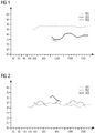
- die zeitlichen Verlaufskurven bei der Erfassung von drei RFID-Datenträgern bei einer ersten Messung,
- Figur 2
- den zeitlichen Verlauf bei einer zweiten Messung, und
- Figur 3
- den zeitlichen Verlauf bei einer dritten Messung.
- FIG. 1
- the time course curves during the acquisition of three RFID data carriers during a first measurement,
- FIG. 2
- the time course in a second measurement, and
- FIG. 3
- the time course in a third measurement.
In der
Auf der Ordinate der Darstellung in der
Es sei angenommen, dass es sich bei der Darstellung in der
In den
Es soll zunächst die Situation aus der
Eine Betrachtung der (mittleren) Amplitude des Signalverlaufs führt hier also nicht zum Ziel, welches darin besteht, den richtigen" der RFID-Datenträger, nämlich den RFID-Datenträger TR1, automatisch zu selektieren.A consideration of the (average) amplitude of the signal curve does not lead to the goal here, which is to automatically select the correct "RFID data carrier, namely the RFID data carrier TR1.
In der
Noch eindeutiger ist die Situation, die in der
Der bei Vergleich der Verlaufskurven ermittelte Übereinstimmungsgrad kann wie beschrieben dazu benutzt werden, um im Falle mehrerer gleichzeitig erfasster RFID-Datenträger denjenigen auszuwählen (zu selektieren), der den höchsten Übereinstimmungsgrad bezüglich seiner im Produktivbetrieb ermittelten Verlaufskurve für den Empfangsparameter aufweist. Zudem kann insbesondere (aber nicht nur) in den Fällen, in denen nur ein RFID-Datenträger im Produktivbetrieb erfasst wird, ein Mindest-Übereinstimmungsgrad zwischen Sollwertkurve und Istwertkurve vorgegeben werden. Damit können Fehlerfassungen aufgrund von Überreichweiten genauso ausgefiltert werden, wie sich auch defekte RFID-Datenträger identifizieren lassen.The degree of agreement determined in comparison of the course curves can be used, as described, to select (select) in the case of several simultaneously detected RFID data carriers, which has the highest degree of correspondence with respect to its operating curve for the reception parameter. moreover In particular (but not only) in cases where only one RFID data carrier is detected during production, a minimum degree of agreement between the setpoint curve and the actual value curve can be specified. This makes it possible to filter out errors due to overreach as well as to identify defective RFID data carriers.
Mittels des vorgeschlagenen Verfahrens und mittels des vorgeschlagenen RFID-Schreib-Lesegerätes ist eine Bewertung des dynamischen Verlaufs eines Empfangsparameters, insbesondere des RSSI-Wertes, anstelle der bislang üblichen Auswertung statistischer Werte möglich. Dies bedeutet, dass die Änderung eines Wertes des betrachteten Empfangsparameters über den zeitlichen Verlauf hinweg als wesentliches Charakteristikum für die Selektion eines RFID-Datenträgers herangezogen werden kann. Das Auswählen (Selektieren) bzw. das Verwerfen von RFID-Datenträgern soll dabei erfindungsgemäß anhand eines Mustervergleichs zwischen einer Referenzkurve und einer Istwert-Kurve stattfinden. Die im vorliegenden Ausführungsbeispiel verwendete Fourier-Transformation und die dadurch realisierte Differenzierung von niederfrequenten und hochfrequenten Signalanteilen ist hier nur als ein exemplarisches Beispiel für eine Analyse des dynamischen Verlaufs zu sehen; im Stand der Technik sind eine Vielzahl von Verfahren der Kennwertbildung für den dynamischen Verlauf eines Ereignisses bekannt, die erfindungsgemäß auch in Kombination miteinander eingesetzt werden können, um eine Sollwertkurve mit den Istwertkurven zu vergleichen und ein Maß für die Ähnlichkeit zwischen zwei Kurven jeweils anzugeben.By means of the proposed method and by means of the proposed RFID read-write device, an evaluation of the dynamic profile of a reception parameter, in particular of the RSSI value, is possible instead of the previously usual evaluation of statistical values. This means that the change of a value of the received parameter over the time course can be used as an essential characteristic for the selection of an RFID data carrier. The selection (selection) or the discarding of RFID data carriers should take place according to the invention on the basis of a pattern comparison between a reference curve and an actual value curve. The Fourier transformation used in the present exemplary embodiment and the differentiation of low-frequency and high-frequency signal components realized thereby can only be seen here as an exemplary example of an analysis of the dynamic profile; In the prior art, a variety of methods of characteristic formation for the dynamic course of an event are known, which can also be used in combination with each other to compare a setpoint curve with the actual value curves and to provide a measure of the similarity between two curves respectively.
Claims (14)
- Method for selecting one from a number of RFID data carriers (TR1, TR2, TR3) detected by an RFID writer-reader, wherein during a training phase a setpoint value for a reception parameter of a specimen RFID data carrier (TR1, TR2, TR3) to be selected is determined,
and wherein during productive operation actual values of reception parameters of detected RFID data carriers (TR1, TR2, TR3) are related to the setpoint value for the selection of one of the detected RFID data carriers (TR1, TR2, TR3), characterized in that
during the training phase in a first temporal sequence a number of detections of at least one specimen RFID data carrier (TR1) are carried out, wherein at least one sequence of setpoint values for at least one reception parameter is determined in the manner of a temporal profile curve,
in that during productive operation in a second temporal sequence a number of detections of the RFID data carriers (TR1, TR2, TR3) situated in the reception region of the RFID writer-reader are carried out, wherein for each of the RFID data carriers (TR1, TR2, TR3) detected here in each case a sequence of actual values is determined in the manner of a temporal profile curve, and
in that the sequences of actual values determined in productive operation are compared in each case with the at least one sequence of setpoint values, wherein one of the RFID data carriers (TR1, TR2, TR3) detected in productive operation is selected on the basis of the respective degree of correspondence. - Method according to Patent Claim 1,
characterized in that
a field strength value, a signal-to-noise ratio or some other qualitative criterion of the radio-frequency signal of the respective RFID data carrier (TR1, TR2, TR3), said signal being detected in each case by the RFID writer-reader, is used as reception parameter. - Method according to either of the preceding patent claims,
characterized in that
the phase angle between transmitted signal and received signal of the radio-frequency signal of the respective RFID data carrier (TR1, TR2, TR3), said signal being detected in each case by the RFID writer-reader, is used as reception parameter. - Method according to any of the preceding patent claims,
characterized in that
the transmission power of the RFID writer-reader is varied in each case as a variation during the temporal sequence. - Method according to any of the preceding patent claims,
characterized in that
the distance between the respective RFID data carrier (TR1, TR2, TR3) and the RFID writer-reader is varied in each case as a variation during the temporal sequence. - Method according to any of the preceding patent claims,
characterized in that
the switching between a plurality of antennas and/or antenna polarizations of the RFID writer-reader is carried out as a variation during the temporal sequence. - Method according to any of the preceding patent claims,
characterized in that
the changing between a plurality of radio channels of the RFID writer-reader is carried out as a variation during the temporal sequence. - Method according to any of Patent Claims 4 - 7,
characterized in that
the variation during the temporal sequence is carried out in an analogous manner in each case during the training phase and during productive operation. - Method according to any of the preceding patent claims,
characterized in that
during the training phase a plurality of sequences of setpoint values are detected, wherein at least one of said sequences is selected as sequence of setpoint values to be used manually by a user or automatically on the basis of information obtained from the content of a data memory of the respective RFID data carrier (TR1, TR2, TR3). - Method according to Patent Claim 9,
characterized in that
the plurality of sequences of setpoint values result from the detection of different RFID data carriers (TR1, TR2, TR3). - Method according to any of the preceding patent claims,
characterized in that
upon the quasi-simultaneous reception of a plurality of RFID data carriers (TR1, TR2, TR3), the latter are distinguished from one another in each case on the basis of a respectively unique identifier or identification number, wherein said identifier or an alias for said identifier is assigned in each case to the different sequences of setpoint values and/or actual values. - Method according to any of the preceding patent claims,
characterized in that
for the comparison of the sequences of setpoint values and actual values, characteristic variables are ascertained in each case from said sequences, wherein a decision about the selection or non-selection of one of the RFID data carriers (TR1, TR2, TR3) corresponding to the sequences of setpoint values is made on the basis of a degree of correspondence of the characteristic variables. - Method according to Patent Claim 12,
characterized in that
a Fourier transformation or some other method for evaluating an analog or digital signal profile is used for ascertaining the characteristic variables. - RFID writer-reader for selecting one from a number of detected RFID data carriers (TR1, TR2, TR3),
wherein the RFID writer-reader is configured in such a way that during a training phase a setpoint value for a reception parameter of a specimen RFID data carrier to be selected is determined,
and wherein during productive operation actual values of reception parameters of detected RFID data carriers (TR1, TR2, TR3) are related to the setpoint value for the selection of one of the detected RFID data carriers (TR1, TR2, TR3), characterized in that
during the training phase in a first temporal sequence a number of detections of at least one specimen RFID data carrier (TR1) are carried out, wherein at least one sequence of setpoint values for at least one reception parameter is determined in the manner of a temporal profile curve,
in that during productive operation in a second temporal sequence a number of detections of the RFID data carriers (TR1, TR2, TR3) situated in the reception region of the RFID writer-reader are carried out, wherein for each of the RFID data carriers (TR1, TR2, TR3) detected here in each case a sequence of actual values is determined in the manner of a temporal profile curve, and in that the sequences of actual values determined in productive operation are compared in each case with the at least one sequence of setpoint values, wherein one of the RFID data carriers (TR1, TR2, TR3) detected in productive operation is selected on the basis of the respective degree of correspondence.
Priority Applications (3)
| Application Number | Priority Date | Filing Date | Title |
|---|---|---|---|
| EP14154305.8A EP2905720B1 (en) | 2014-02-07 | 2014-02-07 | Method and RFID write-read device for selecting an RFID data carrier |
| US14/612,929 US10083330B2 (en) | 2014-02-07 | 2015-02-03 | Method and RFID writer-reader for selecting an RFID data carrier |
| CN201510066796.5A CN104834948B (en) | 2014-02-07 | 2015-02-09 | For selecting the method and RFID reader of RFID data storage media |
Applications Claiming Priority (1)
| Application Number | Priority Date | Filing Date | Title |
|---|---|---|---|
| EP14154305.8A EP2905720B1 (en) | 2014-02-07 | 2014-02-07 | Method and RFID write-read device for selecting an RFID data carrier |
Publications (2)
| Publication Number | Publication Date |
|---|---|
| EP2905720A1 EP2905720A1 (en) | 2015-08-12 |
| EP2905720B1 true EP2905720B1 (en) | 2016-07-27 |
Family
ID=50097566
Family Applications (1)
| Application Number | Title | Priority Date | Filing Date |
|---|---|---|---|
| EP14154305.8A Active EP2905720B1 (en) | 2014-02-07 | 2014-02-07 | Method and RFID write-read device for selecting an RFID data carrier |
Country Status (3)
| Country | Link |
|---|---|
| US (1) | US10083330B2 (en) |
| EP (1) | EP2905720B1 (en) |
| CN (1) | CN104834948B (en) |
Families Citing this family (3)
| Publication number | Priority date | Publication date | Assignee | Title |
|---|---|---|---|---|
| JP7349377B2 (en) * | 2020-01-28 | 2023-09-22 | 東芝テック株式会社 | Wireless tag communication device, wireless tag communication method, and image forming device |
| JP2022097887A (en) * | 2020-12-21 | 2022-07-01 | 東芝テック株式会社 | Sheet transport apparatus and program |
| CN116916429B (en) * | 2023-09-13 | 2023-12-19 | 深圳市地铁集团有限公司 | Dynamic power control method for reader-writer based on fuzzy logic |
Family Cites Families (5)
| Publication number | Priority date | Publication date | Assignee | Title |
|---|---|---|---|---|
| US7639137B2 (en) * | 2005-08-30 | 2009-12-29 | Somnath Mukherjee | System for identifying radio-frequency identification devices |
| US20100060423A1 (en) * | 2008-09-05 | 2010-03-11 | Intermec Technologies Corporation | Radio frequency identification (RFID) reader with multiple receive channels |
| SI2463682T1 (en) | 2010-12-07 | 2013-06-28 | Kapsch Trafficcom Ag | Method for determining the distance of a vehicle to a wireless beacon and wireless beacon for same |
| DE102011100910B4 (en) * | 2011-05-09 | 2016-05-25 | Fraunhofer-Gesellschaft zur Förderung der angewandten Forschung e.V. | Method and system for locating storage units based on UHF transponders in a storage system |
| ES2460917T3 (en) | 2011-08-25 | 2014-05-16 | Siemens Aktiengesellschaft | Procedure and writing-reading device for an arrangement with several non-contact readable transponders |
-
2014
- 2014-02-07 EP EP14154305.8A patent/EP2905720B1/en active Active
-
2015
- 2015-02-03 US US14/612,929 patent/US10083330B2/en active Active
- 2015-02-09 CN CN201510066796.5A patent/CN104834948B/en active Active
Also Published As
| Publication number | Publication date |
|---|---|
| CN104834948B (en) | 2018-02-06 |
| EP2905720A1 (en) | 2015-08-12 |
| US10083330B2 (en) | 2018-09-25 |
| CN104834948A (en) | 2015-08-12 |
| US20150227769A1 (en) | 2015-08-13 |
Similar Documents
| Publication | Publication Date | Title |
|---|---|---|
| DE3345252C2 (en) | ||
| DE3505052C2 (en) | ||
| EP2905720B1 (en) | Method and RFID write-read device for selecting an RFID data carrier | |
| DE102012212856B4 (en) | Method and read / write device for detecting, selecting and reporting at least one of a plurality of contactless readable transponders | |
| EP2087455B1 (en) | Arrangement and method for data acquisition | |
| DE102012211561A1 (en) | Method for operating a speed detection device | |
| DE10352734A1 (en) | Radio frequency identification device | |
| EP2562676B1 (en) | Method and read/write device for an assembly with a number of contactless readable transponders | |
| DE102016108519A1 (en) | Non-invasive load monitoring | |
| DE102009016557B4 (en) | Method for allocating at least one contactless readable data carrier to at least one spatially moving area and device for carrying out the method | |
| WO2014135217A1 (en) | Method and rfid reader for determining a location information for an rfid data carrier to be located | |
| EP1529342B1 (en) | Method for the filtering of noise from measured signals | |
| DE102013111633A1 (en) | Method and device for radio location | |
| EP2990989B1 (en) | Method and read/write apparatus for selecting a wireless tag | |
| DE19827476C1 (en) | Bidirectional digital data transmission method for use between transponder and read/write device | |
| DE102009057349B4 (en) | Method and device for differentiating between useful signals and interfering signals in RFID tags | |
| DE102005037628B3 (en) | Method for detecting an object by means of radar | |
| EP4124539B1 (en) | Method for counting axles with computer-aided evaluation | |
| DE102014203090A1 (en) | Method of identifying a crystallographic candidate phase of a crystal | |
| EP2631848B1 (en) | Transponder assembly, transmitting and receiving apparatus and method for operating a transmission device and reception device | |
| DE102005044151A1 (en) | Mobile data storage e.g. radio frequency identification tag, disposing method for communication, involves disposing storage when difference between distances of writing implement/reader and storage is smaller than maximum difference value | |
| DE102007034591B4 (en) | Method for locating RFID data carriers with high selectivity | |
| DE102016002871A1 (en) | A method of detecting an identification medium in a communication area of an antenna | |
| WO2003016927A1 (en) | Method and device for determining the spectral progression of electromagnetic signals inside a given frequency range | |
| EP4078823A1 (en) | System having a mobile communication device and in particular stationary electric devices and method for operating a system |
Legal Events
| Date | Code | Title | Description |
|---|---|---|---|
| PUAI | Public reference made under article 153(3) epc to a published international application that has entered the european phase |
Free format text: ORIGINAL CODE: 0009012 |
|
| AK | Designated contracting states |
Kind code of ref document: A1 Designated state(s): AL AT BE BG CH CY CZ DE DK EE ES FI FR GB GR HR HU IE IS IT LI LT LU LV MC MK MT NL NO PL PT RO RS SE SI SK SM TR |
|
| AX | Request for extension of the european patent |
Extension state: BA ME |
|
| 17P | Request for examination filed |
Effective date: 20150903 |
|
| RBV | Designated contracting states (corrected) |
Designated state(s): AL AT BE BG CH CY CZ DE DK EE ES FI FR GB GR HR HU IE IS IT LI LT LU LV MC MK MT NL NO PL PT RO RS SE SI SK SM TR |
|
| GRAP | Despatch of communication of intention to grant a patent |
Free format text: ORIGINAL CODE: EPIDOSNIGR1 |
|
| RIC1 | Information provided on ipc code assigned before grant |
Ipc: G06K 7/10 20060101AFI20160126BHEP |
|
| INTG | Intention to grant announced |
Effective date: 20160209 |
|
| GRAS | Grant fee paid |
Free format text: ORIGINAL CODE: EPIDOSNIGR3 |
|
| GRAA | (expected) grant |
Free format text: ORIGINAL CODE: 0009210 |
|
| AK | Designated contracting states |
Kind code of ref document: B1 Designated state(s): AL AT BE BG CH CY CZ DE DK EE ES FI FR GB GR HR HU IE IS IT LI LT LU LV MC MK MT NL NO PL PT RO RS SE SI SK SM TR |
|
| REG | Reference to a national code |
Ref country code: GB Ref legal event code: FG4D Free format text: NOT ENGLISH |
|
| REG | Reference to a national code |
Ref country code: CH Ref legal event code: EP |
|
| REG | Reference to a national code |
Ref country code: AT Ref legal event code: REF Ref document number: 816313 Country of ref document: AT Kind code of ref document: T Effective date: 20160815 |
|
| REG | Reference to a national code |
Ref country code: IE Ref legal event code: FG4D Free format text: LANGUAGE OF EP DOCUMENT: GERMAN |
|
| REG | Reference to a national code |
Ref country code: DE Ref legal event code: R096 Ref document number: 502014001173 Country of ref document: DE |
|
| REG | Reference to a national code |
Ref country code: LT Ref legal event code: MG4D |
|
| REG | Reference to a national code |
Ref country code: NL Ref legal event code: MP Effective date: 20160727 |
|
| PG25 | Lapsed in a contracting state [announced via postgrant information from national office to epo] |
Ref country code: IS Free format text: LAPSE BECAUSE OF FAILURE TO SUBMIT A TRANSLATION OF THE DESCRIPTION OR TO PAY THE FEE WITHIN THE PRESCRIBED TIME-LIMIT Effective date: 20161127 Ref country code: RS Free format text: LAPSE BECAUSE OF FAILURE TO SUBMIT A TRANSLATION OF THE DESCRIPTION OR TO PAY THE FEE WITHIN THE PRESCRIBED TIME-LIMIT Effective date: 20160727 Ref country code: LT Free format text: LAPSE BECAUSE OF FAILURE TO SUBMIT A TRANSLATION OF THE DESCRIPTION OR TO PAY THE FEE WITHIN THE PRESCRIBED TIME-LIMIT Effective date: 20160727 Ref country code: FI Free format text: LAPSE BECAUSE OF FAILURE TO SUBMIT A TRANSLATION OF THE DESCRIPTION OR TO PAY THE FEE WITHIN THE PRESCRIBED TIME-LIMIT Effective date: 20160727 Ref country code: NL Free format text: LAPSE BECAUSE OF FAILURE TO SUBMIT A TRANSLATION OF THE DESCRIPTION OR TO PAY THE FEE WITHIN THE PRESCRIBED TIME-LIMIT Effective date: 20160727 Ref country code: HR Free format text: LAPSE BECAUSE OF FAILURE TO SUBMIT A TRANSLATION OF THE DESCRIPTION OR TO PAY THE FEE WITHIN THE PRESCRIBED TIME-LIMIT Effective date: 20160727 Ref country code: NO Free format text: LAPSE BECAUSE OF FAILURE TO SUBMIT A TRANSLATION OF THE DESCRIPTION OR TO PAY THE FEE WITHIN THE PRESCRIBED TIME-LIMIT Effective date: 20161027 |
|
| REG | Reference to a national code |
Ref country code: FR Ref legal event code: PLFP Year of fee payment: 4 |
|
| PG25 | Lapsed in a contracting state [announced via postgrant information from national office to epo] |
Ref country code: ES Free format text: LAPSE BECAUSE OF FAILURE TO SUBMIT A TRANSLATION OF THE DESCRIPTION OR TO PAY THE FEE WITHIN THE PRESCRIBED TIME-LIMIT Effective date: 20160727 Ref country code: LV Free format text: LAPSE BECAUSE OF FAILURE TO SUBMIT A TRANSLATION OF THE DESCRIPTION OR TO PAY THE FEE WITHIN THE PRESCRIBED TIME-LIMIT Effective date: 20160727 Ref country code: GR Free format text: LAPSE BECAUSE OF FAILURE TO SUBMIT A TRANSLATION OF THE DESCRIPTION OR TO PAY THE FEE WITHIN THE PRESCRIBED TIME-LIMIT Effective date: 20161028 Ref country code: SE Free format text: LAPSE BECAUSE OF FAILURE TO SUBMIT A TRANSLATION OF THE DESCRIPTION OR TO PAY THE FEE WITHIN THE PRESCRIBED TIME-LIMIT Effective date: 20160727 Ref country code: PT Free format text: LAPSE BECAUSE OF FAILURE TO SUBMIT A TRANSLATION OF THE DESCRIPTION OR TO PAY THE FEE WITHIN THE PRESCRIBED TIME-LIMIT Effective date: 20161128 Ref country code: PL Free format text: LAPSE BECAUSE OF FAILURE TO SUBMIT A TRANSLATION OF THE DESCRIPTION OR TO PAY THE FEE WITHIN THE PRESCRIBED TIME-LIMIT Effective date: 20160727 |
|
| PG25 | Lapsed in a contracting state [announced via postgrant information from national office to epo] |
Ref country code: RO Free format text: LAPSE BECAUSE OF FAILURE TO SUBMIT A TRANSLATION OF THE DESCRIPTION OR TO PAY THE FEE WITHIN THE PRESCRIBED TIME-LIMIT Effective date: 20160727 Ref country code: EE Free format text: LAPSE BECAUSE OF FAILURE TO SUBMIT A TRANSLATION OF THE DESCRIPTION OR TO PAY THE FEE WITHIN THE PRESCRIBED TIME-LIMIT Effective date: 20160727 |
|
| REG | Reference to a national code |
Ref country code: DE Ref legal event code: R097 Ref document number: 502014001173 Country of ref document: DE |
|
| PG25 | Lapsed in a contracting state [announced via postgrant information from national office to epo] |
Ref country code: BE Free format text: LAPSE BECAUSE OF NON-PAYMENT OF DUE FEES Effective date: 20170228 Ref country code: DK Free format text: LAPSE BECAUSE OF FAILURE TO SUBMIT A TRANSLATION OF THE DESCRIPTION OR TO PAY THE FEE WITHIN THE PRESCRIBED TIME-LIMIT Effective date: 20160727 Ref country code: SK Free format text: LAPSE BECAUSE OF FAILURE TO SUBMIT A TRANSLATION OF THE DESCRIPTION OR TO PAY THE FEE WITHIN THE PRESCRIBED TIME-LIMIT Effective date: 20160727 Ref country code: SM Free format text: LAPSE BECAUSE OF FAILURE TO SUBMIT A TRANSLATION OF THE DESCRIPTION OR TO PAY THE FEE WITHIN THE PRESCRIBED TIME-LIMIT Effective date: 20160727 Ref country code: CZ Free format text: LAPSE BECAUSE OF FAILURE TO SUBMIT A TRANSLATION OF THE DESCRIPTION OR TO PAY THE FEE WITHIN THE PRESCRIBED TIME-LIMIT Effective date: 20160727 Ref country code: BG Free format text: LAPSE BECAUSE OF FAILURE TO SUBMIT A TRANSLATION OF THE DESCRIPTION OR TO PAY THE FEE WITHIN THE PRESCRIBED TIME-LIMIT Effective date: 20161027 |
|
| PLBE | No opposition filed within time limit |
Free format text: ORIGINAL CODE: 0009261 |
|
| STAA | Information on the status of an ep patent application or granted ep patent |
Free format text: STATUS: NO OPPOSITION FILED WITHIN TIME LIMIT |
|
| 26N | No opposition filed |
Effective date: 20170502 |
|
| PG25 | Lapsed in a contracting state [announced via postgrant information from national office to epo] |
Ref country code: SI Free format text: LAPSE BECAUSE OF FAILURE TO SUBMIT A TRANSLATION OF THE DESCRIPTION OR TO PAY THE FEE WITHIN THE PRESCRIBED TIME-LIMIT Effective date: 20160727 |
|
| PG25 | Lapsed in a contracting state [announced via postgrant information from national office to epo] |
Ref country code: MC Free format text: LAPSE BECAUSE OF FAILURE TO SUBMIT A TRANSLATION OF THE DESCRIPTION OR TO PAY THE FEE WITHIN THE PRESCRIBED TIME-LIMIT Effective date: 20160727 |
|
| REG | Reference to a national code |
Ref country code: CH Ref legal event code: PL |
|
| PG25 | Lapsed in a contracting state [announced via postgrant information from national office to epo] |
Ref country code: CH Free format text: LAPSE BECAUSE OF NON-PAYMENT OF DUE FEES Effective date: 20170228 Ref country code: LI Free format text: LAPSE BECAUSE OF NON-PAYMENT OF DUE FEES Effective date: 20170228 |
|
| REG | Reference to a national code |
Ref country code: IE Ref legal event code: MM4A |
|
| PG25 | Lapsed in a contracting state [announced via postgrant information from national office to epo] |
Ref country code: LU Free format text: LAPSE BECAUSE OF NON-PAYMENT OF DUE FEES Effective date: 20170207 |
|
| REG | Reference to a national code |
Ref country code: FR Ref legal event code: PLFP Year of fee payment: 5 |
|
| REG | Reference to a national code |
Ref country code: BE Ref legal event code: MM Effective date: 20170228 |
|
| PG25 | Lapsed in a contracting state [announced via postgrant information from national office to epo] |
Ref country code: IE Free format text: LAPSE BECAUSE OF NON-PAYMENT OF DUE FEES Effective date: 20170207 |
|
| PG25 | Lapsed in a contracting state [announced via postgrant information from national office to epo] |
Ref country code: MT Free format text: LAPSE BECAUSE OF FAILURE TO SUBMIT A TRANSLATION OF THE DESCRIPTION OR TO PAY THE FEE WITHIN THE PRESCRIBED TIME-LIMIT Effective date: 20160727 |
|
| GBPC | Gb: european patent ceased through non-payment of renewal fee |
Effective date: 20180207 |
|
| PG25 | Lapsed in a contracting state [announced via postgrant information from national office to epo] |
Ref country code: AL Free format text: LAPSE BECAUSE OF FAILURE TO SUBMIT A TRANSLATION OF THE DESCRIPTION OR TO PAY THE FEE WITHIN THE PRESCRIBED TIME-LIMIT Effective date: 20160727 |
|
| PG25 | Lapsed in a contracting state [announced via postgrant information from national office to epo] |
Ref country code: GB Free format text: LAPSE BECAUSE OF NON-PAYMENT OF DUE FEES Effective date: 20180207 |
|
| PG25 | Lapsed in a contracting state [announced via postgrant information from national office to epo] |
Ref country code: HU Free format text: LAPSE BECAUSE OF FAILURE TO SUBMIT A TRANSLATION OF THE DESCRIPTION OR TO PAY THE FEE WITHIN THE PRESCRIBED TIME-LIMIT; INVALID AB INITIO Effective date: 20140207 |
|
| PG25 | Lapsed in a contracting state [announced via postgrant information from national office to epo] |
Ref country code: CY Free format text: LAPSE BECAUSE OF FAILURE TO SUBMIT A TRANSLATION OF THE DESCRIPTION OR TO PAY THE FEE WITHIN THE PRESCRIBED TIME-LIMIT Effective date: 20160727 |
|
| PG25 | Lapsed in a contracting state [announced via postgrant information from national office to epo] |
Ref country code: MK Free format text: LAPSE BECAUSE OF FAILURE TO SUBMIT A TRANSLATION OF THE DESCRIPTION OR TO PAY THE FEE WITHIN THE PRESCRIBED TIME-LIMIT Effective date: 20160727 |
|
| PG25 | Lapsed in a contracting state [announced via postgrant information from national office to epo] |
Ref country code: TR Free format text: LAPSE BECAUSE OF FAILURE TO SUBMIT A TRANSLATION OF THE DESCRIPTION OR TO PAY THE FEE WITHIN THE PRESCRIBED TIME-LIMIT Effective date: 20160727 |
|
| REG | Reference to a national code |
Ref country code: AT Ref legal event code: MM01 Ref document number: 816313 Country of ref document: AT Kind code of ref document: T Effective date: 20190207 |
|
| PG25 | Lapsed in a contracting state [announced via postgrant information from national office to epo] |
Ref country code: AT Free format text: LAPSE BECAUSE OF NON-PAYMENT OF DUE FEES Effective date: 20190207 |
|
| PGFP | Annual fee paid to national office [announced via postgrant information from national office to epo] |
Ref country code: FR Payment date: 20230221 Year of fee payment: 10 |
|
| PGFP | Annual fee paid to national office [announced via postgrant information from national office to epo] |
Ref country code: IT Payment date: 20230221 Year of fee payment: 10 |
|
| PGFP | Annual fee paid to national office [announced via postgrant information from national office to epo] |
Ref country code: DE Payment date: 20230419 Year of fee payment: 10 |