EP2903507B1 - Electromechanical measurement of stapedius muscle/tendon activity - Google Patents
Electromechanical measurement of stapedius muscle/tendon activity Download PDFInfo
- Publication number
- EP2903507B1 EP2903507B1 EP13843508.6A EP13843508A EP2903507B1 EP 2903507 B1 EP2903507 B1 EP 2903507B1 EP 13843508 A EP13843508 A EP 13843508A EP 2903507 B1 EP2903507 B1 EP 2903507B1
- Authority
- EP
- European Patent Office
- Prior art keywords
- transducer
- stapedius
- middle ear
- tissue
- strain gauge
- Prior art date
- Legal status (The legal status is an assumption and is not a legal conclusion. Google has not performed a legal analysis and makes no representation as to the accuracy of the status listed.)
- Active
Links
- 210000001088 stapedius Anatomy 0.000 title claims description 24
- 230000000694 effects Effects 0.000 title claims description 12
- 210000002435 tendon Anatomy 0.000 title description 15
- 210000003205 muscle Anatomy 0.000 title description 12
- 238000005259 measurement Methods 0.000 title description 7
- 239000007943 implant Substances 0.000 claims description 19
- 210000000959 ear middle Anatomy 0.000 claims description 17
- 230000003068 static effect Effects 0.000 claims description 11
- 239000011888 foil Substances 0.000 claims description 9
- 239000000758 substrate Substances 0.000 claims description 8
- 229920006260 polyaryletherketone Polymers 0.000 claims description 6
- 229920000139 polyethylene terephthalate Polymers 0.000 claims description 6
- 239000005020 polyethylene terephthalate Substances 0.000 claims description 6
- 229920002620 polyvinyl fluoride Polymers 0.000 claims description 6
- -1 polyethylene terephthalate Polymers 0.000 claims description 3
- 210000003477 cochlea Anatomy 0.000 description 8
- 230000004044 response Effects 0.000 description 7
- 210000001519 tissue Anatomy 0.000 description 7
- 230000000638 stimulation Effects 0.000 description 6
- 210000001050 stape Anatomy 0.000 description 5
- 210000000860 cochlear nerve Anatomy 0.000 description 3
- 230000008602 contraction Effects 0.000 description 3
- 230000000763 evoking effect Effects 0.000 description 3
- 230000011514 reflex Effects 0.000 description 3
- 230000036982 action potential Effects 0.000 description 2
- 210000003484 anatomy Anatomy 0.000 description 2
- 230000001771 impaired effect Effects 0.000 description 2
- 239000012528 membrane Substances 0.000 description 2
- 238000012545 processing Methods 0.000 description 2
- 210000003454 tympanic membrane Anatomy 0.000 description 2
- 241000878128 Malleus Species 0.000 description 1
- 241000122159 Modiolus Species 0.000 description 1
- 238000003491 array Methods 0.000 description 1
- 230000003542 behavioural effect Effects 0.000 description 1
- 238000005452 bending Methods 0.000 description 1
- 230000005540 biological transmission Effects 0.000 description 1
- 230000015572 biosynthetic process Effects 0.000 description 1
- 210000000988 bone and bone Anatomy 0.000 description 1
- 210000004556 brain Anatomy 0.000 description 1
- 210000000133 brain stem Anatomy 0.000 description 1
- 210000000262 cochlear duct Anatomy 0.000 description 1
- 238000004891 communication Methods 0.000 description 1
- 150000001875 compounds Chemical class 0.000 description 1
- 238000012937 correction Methods 0.000 description 1
- 230000003247 decreasing effect Effects 0.000 description 1
- 230000006735 deficit Effects 0.000 description 1
- 238000006073 displacement reaction Methods 0.000 description 1
- 210000000883 ear external Anatomy 0.000 description 1
- 239000012530 fluid Substances 0.000 description 1
- 230000006870 function Effects 0.000 description 1
- 238000002513 implantation Methods 0.000 description 1
- 210000001785 incus Anatomy 0.000 description 1
- 210000002331 malleus Anatomy 0.000 description 1
- 238000000034 method Methods 0.000 description 1
- 238000012986 modification Methods 0.000 description 1
- 230000004048 modification Effects 0.000 description 1
- 230000001537 neural effect Effects 0.000 description 1
- 230000002093 peripheral effect Effects 0.000 description 1
- 230000002980 postoperative effect Effects 0.000 description 1
- 230000008569 process Effects 0.000 description 1
- 238000011160 research Methods 0.000 description 1
- 239000000523 sample Substances 0.000 description 1
- 210000001079 scala tympani Anatomy 0.000 description 1
- 210000001605 scala vestibuli Anatomy 0.000 description 1
- 239000012781 shape memory material Substances 0.000 description 1
- 230000005236 sound signal Effects 0.000 description 1
- 210000001323 spiral ganglion Anatomy 0.000 description 1
- 238000012360 testing method Methods 0.000 description 1
Images


Classifications
-
- A—HUMAN NECESSITIES
- A61—MEDICAL OR VETERINARY SCIENCE; HYGIENE
- A61B—DIAGNOSIS; SURGERY; IDENTIFICATION
- A61B5/00—Measuring for diagnostic purposes; Identification of persons
- A61B5/24—Detecting, measuring or recording bioelectric or biomagnetic signals of the body or parts thereof
- A61B5/25—Bioelectric electrodes therefor
- A61B5/279—Bioelectric electrodes therefor specially adapted for particular uses
- A61B5/296—Bioelectric electrodes therefor specially adapted for particular uses for electromyography [EMG]
-
- A—HUMAN NECESSITIES
- A61—MEDICAL OR VETERINARY SCIENCE; HYGIENE
- A61B—DIAGNOSIS; SURGERY; IDENTIFICATION
- A61B5/00—Measuring for diagnostic purposes; Identification of persons
- A61B5/12—Audiometering
- A61B5/121—Audiometering evaluating hearing capacity
- A61B5/125—Audiometering evaluating hearing capacity objective methods
-
- A—HUMAN NECESSITIES
- A61—MEDICAL OR VETERINARY SCIENCE; HYGIENE
- A61N—ELECTROTHERAPY; MAGNETOTHERAPY; RADIATION THERAPY; ULTRASOUND THERAPY
- A61N1/00—Electrotherapy; Circuits therefor
- A61N1/18—Applying electric currents by contact electrodes
- A61N1/32—Applying electric currents by contact electrodes alternating or intermittent currents
- A61N1/36—Applying electric currents by contact electrodes alternating or intermittent currents for stimulation
- A61N1/36036—Applying electric currents by contact electrodes alternating or intermittent currents for stimulation of the outer, middle or inner ear
- A61N1/36038—Cochlear stimulation
- A61N1/36039—Cochlear stimulation fitting procedures
-
- H—ELECTRICITY
- H04—ELECTRIC COMMUNICATION TECHNIQUE
- H04R—LOUDSPEAKERS, MICROPHONES, GRAMOPHONE PICK-UPS OR LIKE ACOUSTIC ELECTROMECHANICAL TRANSDUCERS; DEAF-AID SETS; PUBLIC ADDRESS SYSTEMS
- H04R25/00—Deaf-aid sets, i.e. electro-acoustic or electro-mechanical hearing aids; Electric tinnitus maskers providing an auditory perception
- H04R25/60—Mounting or interconnection of hearing aid parts, e.g. inside tips, housings or to ossicles
- H04R25/604—Mounting or interconnection of hearing aid parts, e.g. inside tips, housings or to ossicles of acoustic or vibrational transducers
- H04R25/606—Mounting or interconnection of hearing aid parts, e.g. inside tips, housings or to ossicles of acoustic or vibrational transducers acting directly on the eardrum, the ossicles or the skull, e.g. mastoid, tooth, maxillary or mandibular bone, or mechanically stimulating the cochlea, e.g. at the oval window
-
- A—HUMAN NECESSITIES
- A61—MEDICAL OR VETERINARY SCIENCE; HYGIENE
- A61N—ELECTROTHERAPY; MAGNETOTHERAPY; RADIATION THERAPY; ULTRASOUND THERAPY
- A61N1/00—Electrotherapy; Circuits therefor
- A61N1/02—Details
- A61N1/04—Electrodes
- A61N1/05—Electrodes for implantation or insertion into the body, e.g. heart electrode
- A61N1/0526—Head electrodes
- A61N1/0541—Cochlear electrodes
-
- H—ELECTRICITY
- H04—ELECTRIC COMMUNICATION TECHNIQUE
- H04R—LOUDSPEAKERS, MICROPHONES, GRAMOPHONE PICK-UPS OR LIKE ACOUSTIC ELECTROMECHANICAL TRANSDUCERS; DEAF-AID SETS; PUBLIC ADDRESS SYSTEMS
- H04R2225/00—Details of deaf aids covered by H04R25/00, not provided for in any of its subgroups
- H04R2225/67—Implantable hearing aids or parts thereof not covered by H04R25/606
Definitions
- the present invention relates to hearing prosthesis systems such as cochlear implant systems, and more specifically to measurement of stapedius tissue activity (i.e. contraction and/or stretching in the case of the stapedius muscle and movement in the case of the stapedius tendon) for such systems.
- stapedius tissue activity i.e. contraction and/or stretching in the case of the stapedius muscle and movement in the case of the stapedius tendon
- the cochlea 104 is a long narrow duct wound spirally about its axis for approximately two and a half turns. It includes an upper channel known as the scala vestibuli and a lower channel known as the scala tympani, which are connected by the cochlear duct.
- the cochlea 104 forms an upright spiraling cone with a center called the modiolus where the spiral ganglion cells of the acoustic nerve 113 reside.
- the fluid-filled cochlea 104 functions as a transducer to generate electric pulses which are transmitted to the cochlear nerve 113, and ultimately to the brain.
- a cochlear implant with an implanted stimulation electrode can electrically stimulate auditory nerve tissue with small currents delivered by multiple electrode contacts distributed along the electrode.
- Figure 1 also shows some components of a typical cochlear implant system which includes an external microphone that provides an audio signal input to an external signal processor 111 where various signal processing schemes can be implemented.
- the processed signal is then converted into a digital data format, such as a sequence of data frames, for transmission into the implant 108.
- the implant 108 also performs additional signal processing such as error correction, pulse formation, etc., and produces a stimulation pattern (based on the extracted audio information) that is sent through an electrode lead 109 to an implanted electrode array 110.
- this electrode array 110 includes multiple electrodes on its surface that provide selective stimulation of the cochlea 104.
- the cochlear implant Following surgical implantation, the cochlear implant (CI) must be custom fit to optimize its operation with the specific patient user. For the fitting process, it is important to know if an audible percept is elicited and how loud the percept is. Normally this information is gained using behavioral measures. For example, for each electrode contact the CI user is asked at what stimulation level the first audible percept is perceived (hearing threshold (THR)) and at what stimulation level the percept is too loud (maximum comfort level (MCL)). For CI users with limited auditory experiences or insufficient communication abilities (e.g., small children), these fitting parameters can be determined using objective measures.
- THR heating threshold
- MCL maximum comfort level
- eCAP electrically evoked compound action potential
- US 2011/0137180 A1 discloses a system for fitting a cochlear prosthesis to an infant, comprising a sensor assembly (116) configured to measure a displacement of the stapedius that occurs in response to application of an electrical stimulation.
- Embodiments of the present invention are directed to a device for measuring stapedius tissue activity (i.e., stapedius muscle and/or stapedius tendon activity) that uses a mechanoelectrical transducer having two ends.
- a static end is configured for attachment to the bony pyramid in the middle ear
- a dynamic end is configured for attachment to the stapedius tissue in the middle ear.
- the transducer generates a corresponding electrical sensing signal output when the stapedius tissue moves the dynamic end relative to the static end.
- the transducer may include a mechanical strain gauge for generating the electrical sensing signal output., and there may be a substrate made of polyethylene terephthalate (PET) or polyaryletherketone (PAEK) for supporting the mechanical strain gauge.
- the transducer may use a piezoelectric foil for generating the electrical sensing signal output, and there may be a polyvinyl fluoride (PVF) foil substrate supporting the piezoelectric foil.
- PVF polyvinyl fluoride
- the transducer may form an elongated strip shape or a curved arch shape between the two ends. Or the transducer may form a curved loop shape with elongated parallel sections at the two ends that mechanically amplifies small movements of the stapedial tendon. In some embodiments at least one end may have a curved recess portion configured for attachment to the underlying anatomical structure. And some embodiments may include calibration means for isolating movement of the stapedius tissue from other movements in the middle ear of the patient.
- Embodiments of the present invention also include a hearing implant fitting system and/or a hearing implant system (e.g., a cochlear implant, auditory brainstem implant, or middle ear implant) having a device according to any of the foregoing.
- a hearing implant fitting system e.g., a cochlear implant, auditory brainstem implant, or middle ear implant
- a hearing implant system e.g., a cochlear implant, auditory brainstem implant, or middle ear implant
- Embodiments of the present invention are direct to a mechanoelectrical transducer device for measuring stapedius tissue activity (i.e., stapedius muscle activity and/or stapedius activity), specifically, contraction of the stapedial muscle in response to loud noise.
- a static end of the transducer is configured for attachment to the bony pyramid in the middle ear, and a dynamic end is configured for attachment to the stapedial tendon in the middle ear.
- the dynamic end may also be attached to the stapes directly, preferable to the stapes head.
- the transducer device generates a corresponding electrical sensing signal output when the stapedial tendon moves the dynamic end relative to the static end.
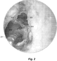
- Figure 2 shows various structural features in the middle ear 200 of a patient with a cochlear implant electrode 201 that passes through an electrode opening 205 in the round window membrane on the outer surface of the patient's cochlea.
- the stapedial tendon 203 is connected at one end to the stapedial muscle inside the bony pyramid 204 (pyramidal eminence) and at the other end to the stapes head 202.
- Figure 3 shows that anatomical context with the addition of a mechanoelectrical transducer 301 formed in an elongated strip shape that has a static end 303 configured for attachment to the bony pyramid 204, and a dynamic end 304 configured for attachment to the stapedial tendon 203.
- the electrical lead 302 from the transducer 301 joins the cochlear implant electrode 201 back away from the electrode opening 205 to isolate the transducer 301 from the effects of micro-movements of the electrode 201.
- the static end 303 of the transducer 301 may be connected to the cochlear implant electrode 201.
- the transducer 301 generates a corresponding electrical sensing signal output when the stapedial tendon 203 moves the dynamic end 304 relative to the static end 303.
- the transducer 301 may specifically be a mechanical strain gauge that changes in electrical impedance when the stapedial muscle 203 contracts in response to loud noise (e.g., MCL threshold).
- the transducer 301 may also include a strain gauge substrate, e.g., made of polyethylene terephthalate (PET) or polyaryletherketone (PAEK), for supporting the mechanical strain gauge.
- PET polyethylene terephthalate
- PAEK polyaryletherketone
- some embodiments may use a transducer 301 based on a piezoelectric foil that generates an electrical signal when the dynamic end 304 moves relative to the static end 303 when the stapedial muscle 203 stretches.
- the transducer 301 have a foil substrate that supports the piezoelectric foil; for example, made of polyvinyl fluoride (PVF).
- Embodiments of the present invention are not specifically limited to an elongated strip shape s shown in Fig. 3 .
- Figure 4A shows a curved arch shape transduce 401 having a mechanical strain gauge 402 at the top of the arch between the dynamic end 403 and the static end 404.
- Figure 4B shows another embodiment of a transducer 401 having a curved loop shape with elongated parallel sections at the two ends 403 and 404.
- the mechanical strain gauge 402 is located on the most highly curved part of the loop that is most sensitive to bending in response to small movements of the stapedial tendon 203; in effect, acting as a mechanical amplifier.
- Figure 4C shows a similar embodiment with an additional strain gauge 405 on the opposite surface of the loop so that when the stapedial muscle 203 stretches in response to loud noise, one of the strain gauges 402/405 is compressed (producing increased impedance), while the other strain gauge 405/402 is stretched (producing decreased impedance).
- At least one end 403 and/or 404 may have a curved recess portion 406 configured for attachment to the underlying anatomical structure-the stapedial tendon 203 and/or the bony pyramid 204.
- the transducer 401 may use a shape memory material that is naturally biased to make the transducer 401 just slightly larger than the space where it is intended to be placed. The surgeon then compresses the ends of the transducer 401 towards each other to fit the transducer 401 in the desired location and position between the bony pyramid 204 and the stapedial tendon 203. When the surgeon releases his grip, the ends expand back out to securely fix the transducer 401 in place.
- Figure 5 shows the structural geometry of another embodiment of an electromechanical transducer 501 for the measurement of stapedius muscle activity with two perpendicular surfaces 502 and 503 with a pair of corresponding perpendicular strain gauges 504 which provide calibration means for isolating movement of the stapedial tendon from other movements in the middle ear of the patient.
- the ossicular chain in the middle ear including the stapes head moves in response.
- the stapedius muscle contracts and the stapedial tendon pulls on the ossicular chain to dampen the signal. That stapedius reflex response to very loud sounds is the only movement of interest for a fitting related measurement.
- an embodiment such as the one shown in Fig. 5 with multiple strain gauges that are perpendicular to each other can detect movements in different spatial dimensions, and the transducer 501 thereby can be calibrated to correlate the transducer output signal with contraction of the stapedial muscle and no other movements inside the middle ear.
Landscapes
- Health & Medical Sciences (AREA)
- Life Sciences & Earth Sciences (AREA)
- Engineering & Computer Science (AREA)
- General Health & Medical Sciences (AREA)
- Otolaryngology (AREA)
- Physics & Mathematics (AREA)
- Veterinary Medicine (AREA)
- Animal Behavior & Ethology (AREA)
- Biomedical Technology (AREA)
- Public Health (AREA)
- Pathology (AREA)
- Medical Informatics (AREA)
- Surgery (AREA)
- Molecular Biology (AREA)
- Heart & Thoracic Surgery (AREA)
- Audiology, Speech & Language Pathology (AREA)
- Biophysics (AREA)
- Acoustics & Sound (AREA)
- Multimedia (AREA)
- Radiology & Medical Imaging (AREA)
- Nuclear Medicine, Radiotherapy & Molecular Imaging (AREA)
- Signal Processing (AREA)
- Neurosurgery (AREA)
- Prostheses (AREA)
Description
- The present invention relates to hearing prosthesis systems such as cochlear implant systems, and more specifically to measurement of stapedius tissue activity (i.e. contraction and/or stretching in the case of the stapedius muscle and movement in the case of the stapedius tendon) for such systems.
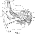
- Most sounds are transmitted in a normal ear as shown in
Figure 1 through theouter ear 101 to the tympanic membrane (eardrum) 102, which moves the bones of the middle ear 103 (malleus, incus, and stapes) that vibrate the oval window and round window openings of thecochlea 104. Thecochlea 104 is a long narrow duct wound spirally about its axis for approximately two and a half turns. It includes an upper channel known as the scala vestibuli and a lower channel known as the scala tympani, which are connected by the cochlear duct. Thecochlea 104 forms an upright spiraling cone with a center called the modiolus where the spiral ganglion cells of theacoustic nerve 113 reside. In response to received sounds transmitted by themiddle ear 103, the fluid-filledcochlea 104 functions as a transducer to generate electric pulses which are transmitted to thecochlear nerve 113, and ultimately to the brain. - Hearing is impaired when there are problems in the ability to transduce external sounds into meaningful action potentials along the neural substrate of the
cochlea 104. To improve impaired hearing, auditory prostheses have been developed. For example, when the impairment is associated with thecochlea 104, a cochlear implant with an implanted stimulation electrode can electrically stimulate auditory nerve tissue with small currents delivered by multiple electrode contacts distributed along the electrode. -
Figure 1 also shows some components of a typical cochlear implant system which includes an external microphone that provides an audio signal input to anexternal signal processor 111 where various signal processing schemes can be implemented. The processed signal is then converted into a digital data format, such as a sequence of data frames, for transmission into theimplant 108. Besides receiving the processed audio information, theimplant 108 also performs additional signal processing such as error correction, pulse formation, etc., and produces a stimulation pattern (based on the extracted audio information) that is sent through anelectrode lead 109 to an implantedelectrode array 110. Typically, thiselectrode array 110 includes multiple electrodes on its surface that provide selective stimulation of thecochlea 104. - Following surgical implantation, the cochlear implant (CI) must be custom fit to optimize its operation with the specific patient user. For the fitting process, it is important to know if an audible percept is elicited and how loud the percept is. Normally this information is gained using behavioral measures. For example, for each electrode contact the CI user is asked at what stimulation level the first audible percept is perceived (hearing threshold (THR)) and at what stimulation level the percept is too loud (maximum comfort level (MCL)). For CI users with limited auditory experiences or insufficient communication abilities (e.g., small children), these fitting parameters can be determined using objective measures.
- One commonly used objective measure is the electrically evoked compound action potential (eCAP) which can be easily measured, but shows weak correlations with the MCL (r=0.57) and THR (r=0.55). See, for example, Miller et al., The Clinical Application Of Potentials Evoked From The Peripheral Auditory System, Hearing Research, 242(1-2), 184-197 (2008). The electrically evoked stapedius reflex threshold (eSRT) shows high correlations with the MCL. See, for example, Stephan, K. & Welzl-Müller, K., Post-Operative Stapedius Reflex Tests With Simultaneous Loudness Scaling In Patients Supplied With Cochlear Implants, Audiology, 39, 13-18 (2000) (r=0.92); and Polak, M.; Hodges, A. & Balkany, T ECAP, ESR and Subjective Levels For Two Different Nucleus 24 Electrode Arrays, Otology & Neurotology, 2005, 26, 639-645, (r= 0.93 - 0.95); But the eSRT electrical measurement is difficult to measure reliably; for example, movement artifacts of the impedance probe can introduce measurement artifacts. However, it has turned out that electromyographic (EMG) measurement of the activity of the stapedius musle is fairly difficult for various reasons.
-
US 2011/0137180 A1 discloses a system for fitting a cochlear prosthesis to an infant, comprising a sensor assembly (116) configured to measure a displacement of the stapedius that occurs in response to application of an electrical stimulation. - Embodiments of the present invention are directed to a device for measuring stapedius tissue activity (i.e., stapedius muscle and/or stapedius tendon activity) that uses a mechanoelectrical transducer having two ends. A static end is configured for attachment to the bony pyramid in the middle ear, and a dynamic end is configured for attachment to the stapedius tissue in the middle ear. The transducer generates a corresponding electrical sensing signal output when the stapedius tissue moves the dynamic end relative to the static end.
- In specific embodiments, the transducer may include a mechanical strain gauge for generating the electrical sensing signal output., and there may be a substrate made of polyethylene terephthalate (PET) or polyaryletherketone (PAEK) for supporting the mechanical strain gauge. Or the transducer may use a piezoelectric foil for generating the electrical sensing signal output, and there may be a polyvinyl fluoride (PVF) foil substrate supporting the piezoelectric foil.
- The transducer may form an elongated strip shape or a curved arch shape between the two ends. Or the transducer may form a curved loop shape with elongated parallel sections at the two ends that mechanically amplifies small movements of the stapedial tendon. In some embodiments at least one end may have a curved recess portion configured for attachment to the underlying anatomical structure. And some embodiments may include calibration means for isolating movement of the stapedius tissue from other movements in the middle ear of the patient.
- Embodiments of the present invention also include a hearing implant fitting system and/or a hearing implant system (e.g., a cochlear implant, auditory brainstem implant, or middle ear implant) having a device according to any of the foregoing.
-
-
Fig. 1 shows anatomical structures of a human ear having a cochlear implant system. -
Fig. 2 shows various structural features in the middle ear with a cochlear implant electrode passing through an opening in the round window membrane. -
Fig. 3 shows a mechanoelectrical transducer attached to the stapedial tendon according to one specific embodiment of the present invention. -
Fig. 4 A-D shows various structural geometries of alternative embodiments. -
Fig. 5 shows the structural geometry of another embodiment of the present invention. - Embodiments of the present invention are direct to a mechanoelectrical transducer device for measuring stapedius tissue activity (i.e., stapedius muscle activity and/or stapedius activity), specifically, contraction of the stapedial muscle in response to loud noise. A static end of the transducer is configured for attachment to the bony pyramid in the middle ear, and a dynamic end is configured for attachment to the stapedial tendon in the middle ear. Alternatively, the dynamic end may also be attached to the stapes directly, preferable to the stapes head. The transducer device generates a corresponding electrical sensing signal output when the stapedial tendon moves the dynamic end relative to the static end.
-
Figure 2 shows various structural features in the middle ear 200 of a patient with acochlear implant electrode 201 that passes through an electrode opening 205 in the round window membrane on the outer surface of the patient's cochlea. Thestapedial tendon 203 is connected at one end to the stapedial muscle inside the bony pyramid 204 (pyramidal eminence) and at the other end to thestapes head 202.Figure 3 shows that anatomical context with the addition of amechanoelectrical transducer 301 formed in an elongated strip shape that has astatic end 303 configured for attachment to thebony pyramid 204, and adynamic end 304 configured for attachment to thestapedial tendon 203. Theelectrical lead 302 from thetransducer 301 joins thecochlear implant electrode 201 back away from the electrode opening 205 to isolate thetransducer 301 from the effects of micro-movements of theelectrode 201. Alternatively rather than connecting thetransducer 301 to thebony pyramid 204, in some embodiments thestatic end 303 of thetransducer 301 may be connected to thecochlear implant electrode 201. - The
transducer 301 generates a corresponding electrical sensing signal output when thestapedial tendon 203 moves thedynamic end 304 relative to thestatic end 303. For example, thetransducer 301 may specifically be a mechanical strain gauge that changes in electrical impedance when thestapedial muscle 203 contracts in response to loud noise (e.g., MCL threshold). In such embodiments, thetransducer 301 may also include a strain gauge substrate, e.g., made of polyethylene terephthalate (PET) or polyaryletherketone (PAEK), for supporting the mechanical strain gauge. - Rather than a mechanical strain gauge, some embodiments may use a
transducer 301 based on a piezoelectric foil that generates an electrical signal when thedynamic end 304 moves relative to thestatic end 303 when thestapedial muscle 203 stretches. In such embodiments, thetransducer 301 have a foil substrate that supports the piezoelectric foil; for example, made of polyvinyl fluoride (PVF). - Embodiments of the present invention are not specifically limited to an elongated strip shape s shown in
Fig. 3 . For example,Figure 4A shows a curved arch shape transduce 401 having amechanical strain gauge 402 at the top of the arch between thedynamic end 403 and thestatic end 404.Figure 4B shows another embodiment of atransducer 401 having a curved loop shape with elongated parallel sections at the twoends mechanical strain gauge 402 is located on the most highly curved part of the loop that is most sensitive to bending in response to small movements of thestapedial tendon 203; in effect, acting as a mechanical amplifier.Figure 4C shows a similar embodiment with anadditional strain gauge 405 on the opposite surface of the loop so that when thestapedial muscle 203 stretches in response to loud noise, one of thestrain gauges 402/405 is compressed (producing increased impedance), while theother strain gauge 405/402 is stretched (producing decreased impedance). - As shown in
Figure 4D , on sometransducers 401 at least oneend 403 and/or 404 may have acurved recess portion 406 configured for attachment to the underlying anatomical structure-thestapedial tendon 203 and/or thebony pyramid 204. To affix an archshaped transducer 401 such as the ones shown inFig. 4A and 4D , thetransducer 401 may use a shape memory material that is naturally biased to make thetransducer 401 just slightly larger than the space where it is intended to be placed. The surgeon then compresses the ends of thetransducer 401 towards each other to fit thetransducer 401 in the desired location and position between thebony pyramid 204 and thestapedial tendon 203. When the surgeon releases his grip, the ends expand back out to securely fix thetransducer 401 in place. -
Figure 5 shows the structural geometry of another embodiment of anelectromechanical transducer 501 for the measurement of stapedius muscle activity with twoperpendicular surfaces perpendicular strain gauges 504 which provide calibration means for isolating movement of the stapedial tendon from other movements in the middle ear of the patient. Specifically, when the ear is exposed to any sound, the ossicular chain in the middle ear including the stapes head moves in response. When the incoming sound is very loud, the stapedius muscle contracts and the stapedial tendon pulls on the ossicular chain to dampen the signal. That stapedius reflex response to very loud sounds is the only movement of interest for a fitting related measurement. So an embodiment such as the one shown inFig. 5 with multiple strain gauges that are perpendicular to each other can detect movements in different spatial dimensions, and thetransducer 501 thereby can be calibrated to correlate the transducer output signal with contraction of the stapedial muscle and no other movements inside the middle ear. - Although various exemplary embodiments of the invention have been disclosed, it should be apparent to those skilled in the art that various changes and modifications can be made which will achieve some of the advantages of the invention without departing from the true scope of the invention as determined by the claims.
Claims (13)
- A device for measuring middle ear stapedius tissue activity comprising:a mechanoelectrical transducer having two ends:i. a static end configured for attachment to the bony pyramid in the middle ear of a patient, andii. a dynamic end configured for attachment to stapedius tissue in the middle ear of the patient;wherein the transducer generates a corresponding electrical sensing signal output when the stapedius tissue moves the dynamic end relative to the static end.
- A device according to claim 1, wherein the transducer includes a mechanical strain gauge for generating the electrical sensing signal output.
- A device according to claim 2, wherein the transducer includes a polyethylene terephthalate (PET) substrate supporting the mechanical strain gauge.
- A device according to claim 2, wherein the transducer includes a polyaryletherketone (PAEK) substrate supporting the mechanical strain gauge.
- A device according to claim 1, wherein the transducer includes a piezoelectric foil for generating the electrical sensing signal output.
- A device according to claim 5, wherein the transducer includes a polyvinyl fluoride (PVF) foil substrate supporting the piezoelectric foil.
- A device according to claim 1, wherein the transducer forms an elongated strip shape between the two ends.
- A device according to claim 1, wherein the transducer forms a curved arch shape between the two ends.
- A device according to claim 1, wherein the transducer forms a curved loop shape with elongated parallel sections at the two ends that mechanically amplifies small movements of the stapedius tissue.
- A device according to claim 1, wherein at least one end has a curved recess portion configured for attachment of the at least one end.
- A device according to claim 1, further including calibration means for isolating movement of the stapedial tissue from other movements in the middle ear of the patient.
- A hearing implant fitting system having a device according to any of claims 1-11.
- A hearing implant system having a device according to any of claims 1-11.
Applications Claiming Priority (2)
| Application Number | Priority Date | Filing Date | Title |
|---|---|---|---|
| DE102012218153 | 2012-10-04 | ||
| PCT/US2013/063383 WO2014055823A1 (en) | 2012-10-04 | 2013-10-04 | Electromechanical measurement of stapedius muscle/tendon activity |
Publications (3)
| Publication Number | Publication Date |
|---|---|
| EP2903507A1 EP2903507A1 (en) | 2015-08-12 |
| EP2903507A4 EP2903507A4 (en) | 2016-07-27 |
| EP2903507B1 true EP2903507B1 (en) | 2017-01-11 |
Family
ID=50433238
Family Applications (1)
| Application Number | Title | Priority Date | Filing Date |
|---|---|---|---|
| EP13843508.6A Active EP2903507B1 (en) | 2012-10-04 | 2013-10-04 | Electromechanical measurement of stapedius muscle/tendon activity |
Country Status (5)
| Country | Link |
|---|---|
| US (1) | US20140100471A1 (en) |
| EP (1) | EP2903507B1 (en) |
| CN (1) | CN104755022B (en) |
| AU (1) | AU2013326920B2 (en) |
| WO (1) | WO2014055823A1 (en) |
Families Citing this family (2)
| Publication number | Priority date | Publication date | Assignee | Title |
|---|---|---|---|---|
| US10772563B2 (en) * | 2016-02-26 | 2020-09-15 | Med-El Elektromedizinische Geraete Gmbh | Detection of electrically evoked stapedius reflex |
| US10357656B2 (en) | 2016-07-12 | 2019-07-23 | Cochlear Limited | Hearing prosthesis programming |
Family Cites Families (13)
| Publication number | Priority date | Publication date | Assignee | Title |
|---|---|---|---|---|
| DE4236985C1 (en) * | 1992-11-04 | 1994-02-24 | Hottinger Messtechnik Baldwin | Strain gauges |
| CA2258008A1 (en) * | 1996-06-20 | 1997-12-24 | Advanced Bionics Corporation | Self-adjusting cochlear implant system and method for fitting same |
| US5899847A (en) * | 1996-08-07 | 1999-05-04 | St. Croix Medical, Inc. | Implantable middle-ear hearing assist system using piezoelectric transducer film |
| US6208882B1 (en) * | 1998-06-03 | 2001-03-27 | Advanced Bionics Corporation | Stapedius reflex electrode and connector |
| NO309635B1 (en) * | 2000-03-14 | 2001-03-05 | Sensotech As | erectile Aid |
| DE202004001008U1 (en) * | 2004-01-23 | 2004-04-01 | Heinz Kurz Gmbh Medizintechnik | ossicle prosthesis |
| EP1737533B1 (en) * | 2004-03-15 | 2014-07-16 | Med-El Elektromedizinische Geräte GmbH | Cochlear implant electrode with adjustable subdivision for middle ear functions |
| US8121687B2 (en) * | 2004-11-01 | 2012-02-21 | Proteus Biomedical, Inc. | Cardiac motion characterization by strain measurement |
| WO2008033791A1 (en) * | 2006-09-12 | 2008-03-20 | Med-El Elektromedizinische Geraete Gmbh | Middle ear fixation structure |
| GB2449114A (en) * | 2007-05-11 | 2008-11-12 | Sentient Medical Ltd | Middle ear implant with piezoelectric actuator acting on stapes footplate |
| US9014778B2 (en) * | 2008-06-24 | 2015-04-21 | Biosense Webster, Inc. | Disposable patch and reusable sensor assembly for use in medical device localization and mapping systems |
| WO2010099158A1 (en) * | 2009-02-26 | 2010-09-02 | Arkema Inc. | Electrode arrays based on polyetherketoneketone |
| EP2506923A1 (en) * | 2009-12-04 | 2012-10-10 | Advanced Bionics AG | Systems and methods for fitting a cochlear implant system to a patient based on stapedius displacement |
-
2013
- 2013-10-04 WO PCT/US2013/063383 patent/WO2014055823A1/en active Application Filing
- 2013-10-04 US US14/045,913 patent/US20140100471A1/en not_active Abandoned
- 2013-10-04 AU AU2013326920A patent/AU2013326920B2/en active Active
- 2013-10-04 CN CN201380052262.6A patent/CN104755022B/en active Active
- 2013-10-04 EP EP13843508.6A patent/EP2903507B1/en active Active
Non-Patent Citations (1)
| Title |
|---|
| None * |
Also Published As
| Publication number | Publication date |
|---|---|
| CN104755022A (en) | 2015-07-01 |
| AU2013326920B2 (en) | 2016-06-09 |
| US20140100471A1 (en) | 2014-04-10 |
| EP2903507A4 (en) | 2016-07-27 |
| AU2013326920A1 (en) | 2015-04-02 |
| CN104755022B (en) | 2017-01-18 |
| EP2903507A1 (en) | 2015-08-12 |
| WO2014055823A1 (en) | 2014-04-10 |
Similar Documents
| Publication | Publication Date | Title |
|---|---|---|
| AU2017223495B2 (en) | Detection of electrically evoked stapedius reflex | |
| US8103354B2 (en) | Systems and methods for determining a threshold current level required to evoke a stapedial muscle reflex | |
| US7925355B2 (en) | Systems and methods for determining a threshold current level required to evoke a stapedial muscle reflex | |
| EP2688640B1 (en) | Post-auricular muscle response based hearing prosthesis fitting | |
| US10413728B2 (en) | Electrocochleography testing in hearing prostheses | |
| CN109475738B (en) | Hearing prosthesis programming | |
| US20110137180A1 (en) | Systems and Methods for Fitting a Cochlear Implant System to a Patient Based on Stapedius Displacement | |
| EP3519040B1 (en) | Perception change-based adjustments in hearing prostheses | |
| US8265767B2 (en) | Stochastic stimulation in a hearing prosthesis | |
| EP2903507B1 (en) | Electromechanical measurement of stapedius muscle/tendon activity | |
| CN110430848A (en) | The middle ear implant coupler of mechanical cochlear stimulation is carried out by round window | |
| Warkentin et al. | Hessler et al.(43) Pub. Date: Apr. 10, 2014 |
Legal Events
| Date | Code | Title | Description |
|---|---|---|---|
| PUAI | Public reference made under article 153(3) epc to a published international application that has entered the european phase |
Free format text: ORIGINAL CODE: 0009012 |
|
| 17P | Request for examination filed |
Effective date: 20150320 |
|
| AK | Designated contracting states |
Kind code of ref document: A1 Designated state(s): AL AT BE BG CH CY CZ DE DK EE ES FI FR GB GR HR HU IE IS IT LI LT LU LV MC MK MT NL NO PL PT RO RS SE SI SK SM TR |
|
| AX | Request for extension of the european patent |
Extension state: BA ME |
|
| RIN1 | Information on inventor provided before grant (corrected) |
Inventor name: SPECHT, OLAF Inventor name: HESSLER, ROLAND Inventor name: OVARI, ATTILA Inventor name: DHANASINGH, ANANDHAN Inventor name: SCHMIDT, WOLFRAM Inventor name: BEHREND, DETLEF Inventor name: PAU, HANS WILHELM Inventor name: WARKENTIN, MAREIKE Inventor name: DEL CARMEN FUENTES, MARIA |
|
| DAX | Request for extension of the european patent (deleted) | ||
| RA4 | Supplementary search report drawn up and despatched (corrected) |
Effective date: 20160623 |
|
| RIC1 | Information provided on ipc code assigned before grant |
Ipc: A61B 5/04 20060101AFI20160617BHEP Ipc: A61N 1/36 20060101ALI20160617BHEP Ipc: H04R 25/00 20060101ALI20160617BHEP Ipc: A61B 5/0492 20060101ALI20160617BHEP |
|
| RIC1 | Information provided on ipc code assigned before grant |
Ipc: A61B 5/04 20060101AFI20160811BHEP Ipc: A61N 1/36 20060101ALI20160811BHEP Ipc: A61B 5/12 20060101ALI20160811BHEP Ipc: A61B 5/0492 20060101ALI20160811BHEP Ipc: H04R 25/00 20060101ALI20160811BHEP |
|
| GRAP | Despatch of communication of intention to grant a patent |
Free format text: ORIGINAL CODE: EPIDOSNIGR1 |
|
| INTG | Intention to grant announced |
Effective date: 20160916 |
|
| GRAS | Grant fee paid |
Free format text: ORIGINAL CODE: EPIDOSNIGR3 |
|
| GRAA | (expected) grant |
Free format text: ORIGINAL CODE: 0009210 |
|
| AK | Designated contracting states |
Kind code of ref document: B1 Designated state(s): AL AT BE BG CH CY CZ DE DK EE ES FI FR GB GR HR HU IE IS IT LI LT LU LV MC MK MT NL NO PL PT RO RS SE SI SK SM TR |
|
| REG | Reference to a national code |
Ref country code: GB Ref legal event code: FG4D |
|
| REG | Reference to a national code |
Ref country code: CH Ref legal event code: EP |
|
| REG | Reference to a national code |
Ref country code: AT Ref legal event code: REF Ref document number: 860501 Country of ref document: AT Kind code of ref document: T Effective date: 20170115 |
|
| REG | Reference to a national code |
Ref country code: IE Ref legal event code: FG4D |
|
| REG | Reference to a national code |
Ref country code: DE Ref legal event code: R096 Ref document number: 602013016613 Country of ref document: DE |
|
| REG | Reference to a national code |
Ref country code: LT Ref legal event code: MG4D |
|
| REG | Reference to a national code |
Ref country code: NL Ref legal event code: MP Effective date: 20170111 |
|
| REG | Reference to a national code |
Ref country code: AT Ref legal event code: MK05 Ref document number: 860501 Country of ref document: AT Kind code of ref document: T Effective date: 20170111 |
|
| PG25 | Lapsed in a contracting state [announced via postgrant information from national office to epo] |
Ref country code: NL Free format text: LAPSE BECAUSE OF FAILURE TO SUBMIT A TRANSLATION OF THE DESCRIPTION OR TO PAY THE FEE WITHIN THE PRESCRIBED TIME-LIMIT Effective date: 20170111 |
|
| PG25 | Lapsed in a contracting state [announced via postgrant information from national office to epo] |
Ref country code: LT Free format text: LAPSE BECAUSE OF FAILURE TO SUBMIT A TRANSLATION OF THE DESCRIPTION OR TO PAY THE FEE WITHIN THE PRESCRIBED TIME-LIMIT Effective date: 20170111 Ref country code: FI Free format text: LAPSE BECAUSE OF FAILURE TO SUBMIT A TRANSLATION OF THE DESCRIPTION OR TO PAY THE FEE WITHIN THE PRESCRIBED TIME-LIMIT Effective date: 20170111 Ref country code: IS Free format text: LAPSE BECAUSE OF FAILURE TO SUBMIT A TRANSLATION OF THE DESCRIPTION OR TO PAY THE FEE WITHIN THE PRESCRIBED TIME-LIMIT Effective date: 20170511 Ref country code: GR Free format text: LAPSE BECAUSE OF FAILURE TO SUBMIT A TRANSLATION OF THE DESCRIPTION OR TO PAY THE FEE WITHIN THE PRESCRIBED TIME-LIMIT Effective date: 20170412 Ref country code: NO Free format text: LAPSE BECAUSE OF FAILURE TO SUBMIT A TRANSLATION OF THE DESCRIPTION OR TO PAY THE FEE WITHIN THE PRESCRIBED TIME-LIMIT Effective date: 20170411 Ref country code: HR Free format text: LAPSE BECAUSE OF FAILURE TO SUBMIT A TRANSLATION OF THE DESCRIPTION OR TO PAY THE FEE WITHIN THE PRESCRIBED TIME-LIMIT Effective date: 20170111 |
|
| PG25 | Lapsed in a contracting state [announced via postgrant information from national office to epo] |
Ref country code: BG Free format text: LAPSE BECAUSE OF FAILURE TO SUBMIT A TRANSLATION OF THE DESCRIPTION OR TO PAY THE FEE WITHIN THE PRESCRIBED TIME-LIMIT Effective date: 20170411 Ref country code: ES Free format text: LAPSE BECAUSE OF FAILURE TO SUBMIT A TRANSLATION OF THE DESCRIPTION OR TO PAY THE FEE WITHIN THE PRESCRIBED TIME-LIMIT Effective date: 20170111 Ref country code: AT Free format text: LAPSE BECAUSE OF FAILURE TO SUBMIT A TRANSLATION OF THE DESCRIPTION OR TO PAY THE FEE WITHIN THE PRESCRIBED TIME-LIMIT Effective date: 20170111 Ref country code: PT Free format text: LAPSE BECAUSE OF FAILURE TO SUBMIT A TRANSLATION OF THE DESCRIPTION OR TO PAY THE FEE WITHIN THE PRESCRIBED TIME-LIMIT Effective date: 20170511 Ref country code: RS Free format text: LAPSE BECAUSE OF FAILURE TO SUBMIT A TRANSLATION OF THE DESCRIPTION OR TO PAY THE FEE WITHIN THE PRESCRIBED TIME-LIMIT Effective date: 20170111 Ref country code: SE Free format text: LAPSE BECAUSE OF FAILURE TO SUBMIT A TRANSLATION OF THE DESCRIPTION OR TO PAY THE FEE WITHIN THE PRESCRIBED TIME-LIMIT Effective date: 20170111 Ref country code: LV Free format text: LAPSE BECAUSE OF FAILURE TO SUBMIT A TRANSLATION OF THE DESCRIPTION OR TO PAY THE FEE WITHIN THE PRESCRIBED TIME-LIMIT Effective date: 20170111 Ref country code: PL Free format text: LAPSE BECAUSE OF FAILURE TO SUBMIT A TRANSLATION OF THE DESCRIPTION OR TO PAY THE FEE WITHIN THE PRESCRIBED TIME-LIMIT Effective date: 20170111 |
|
| REG | Reference to a national code |
Ref country code: DE Ref legal event code: R097 Ref document number: 602013016613 Country of ref document: DE |
|
| PG25 | Lapsed in a contracting state [announced via postgrant information from national office to epo] |
Ref country code: EE Free format text: LAPSE BECAUSE OF FAILURE TO SUBMIT A TRANSLATION OF THE DESCRIPTION OR TO PAY THE FEE WITHIN THE PRESCRIBED TIME-LIMIT Effective date: 20170111 Ref country code: IT Free format text: LAPSE BECAUSE OF FAILURE TO SUBMIT A TRANSLATION OF THE DESCRIPTION OR TO PAY THE FEE WITHIN THE PRESCRIBED TIME-LIMIT Effective date: 20170111 Ref country code: SK Free format text: LAPSE BECAUSE OF FAILURE TO SUBMIT A TRANSLATION OF THE DESCRIPTION OR TO PAY THE FEE WITHIN THE PRESCRIBED TIME-LIMIT Effective date: 20170111 Ref country code: CZ Free format text: LAPSE BECAUSE OF FAILURE TO SUBMIT A TRANSLATION OF THE DESCRIPTION OR TO PAY THE FEE WITHIN THE PRESCRIBED TIME-LIMIT Effective date: 20170111 Ref country code: RO Free format text: LAPSE BECAUSE OF FAILURE TO SUBMIT A TRANSLATION OF THE DESCRIPTION OR TO PAY THE FEE WITHIN THE PRESCRIBED TIME-LIMIT Effective date: 20170111 |
|
| REG | Reference to a national code |
Ref country code: FR Ref legal event code: PLFP Year of fee payment: 5 |
|
| PLBE | No opposition filed within time limit |
Free format text: ORIGINAL CODE: 0009261 |
|
| STAA | Information on the status of an ep patent application or granted ep patent |
Free format text: STATUS: NO OPPOSITION FILED WITHIN TIME LIMIT |
|
| PG25 | Lapsed in a contracting state [announced via postgrant information from national office to epo] |
Ref country code: SM Free format text: LAPSE BECAUSE OF FAILURE TO SUBMIT A TRANSLATION OF THE DESCRIPTION OR TO PAY THE FEE WITHIN THE PRESCRIBED TIME-LIMIT Effective date: 20170111 Ref country code: DK Free format text: LAPSE BECAUSE OF FAILURE TO SUBMIT A TRANSLATION OF THE DESCRIPTION OR TO PAY THE FEE WITHIN THE PRESCRIBED TIME-LIMIT Effective date: 20170111 |
|
| 26N | No opposition filed |
Effective date: 20171012 |
|
| PG25 | Lapsed in a contracting state [announced via postgrant information from national office to epo] |
Ref country code: SI Free format text: LAPSE BECAUSE OF FAILURE TO SUBMIT A TRANSLATION OF THE DESCRIPTION OR TO PAY THE FEE WITHIN THE PRESCRIBED TIME-LIMIT Effective date: 20170111 |
|
| PG25 | Lapsed in a contracting state [announced via postgrant information from national office to epo] |
Ref country code: MC Free format text: LAPSE BECAUSE OF FAILURE TO SUBMIT A TRANSLATION OF THE DESCRIPTION OR TO PAY THE FEE WITHIN THE PRESCRIBED TIME-LIMIT Effective date: 20170111 |
|
| REG | Reference to a national code |
Ref country code: CH Ref legal event code: PL |
|
| REG | Reference to a national code |
Ref country code: IE Ref legal event code: MM4A |
|
| PG25 | Lapsed in a contracting state [announced via postgrant information from national office to epo] |
Ref country code: LU Free format text: LAPSE BECAUSE OF NON-PAYMENT OF DUE FEES Effective date: 20171004 Ref country code: LI Free format text: LAPSE BECAUSE OF NON-PAYMENT OF DUE FEES Effective date: 20171031 Ref country code: CH Free format text: LAPSE BECAUSE OF NON-PAYMENT OF DUE FEES Effective date: 20171031 |
|
| REG | Reference to a national code |
Ref country code: BE Ref legal event code: MM Effective date: 20171031 |
|
| PG25 | Lapsed in a contracting state [announced via postgrant information from national office to epo] |
Ref country code: BE Free format text: LAPSE BECAUSE OF NON-PAYMENT OF DUE FEES Effective date: 20171031 |
|
| PG25 | Lapsed in a contracting state [announced via postgrant information from national office to epo] |
Ref country code: MT Free format text: LAPSE BECAUSE OF NON-PAYMENT OF DUE FEES Effective date: 20171004 |
|
| REG | Reference to a national code |
Ref country code: FR Ref legal event code: PLFP Year of fee payment: 6 |
|
| PG25 | Lapsed in a contracting state [announced via postgrant information from national office to epo] |
Ref country code: IE Free format text: LAPSE BECAUSE OF NON-PAYMENT OF DUE FEES Effective date: 20171004 |
|
| PG25 | Lapsed in a contracting state [announced via postgrant information from national office to epo] |
Ref country code: HU Free format text: LAPSE BECAUSE OF FAILURE TO SUBMIT A TRANSLATION OF THE DESCRIPTION OR TO PAY THE FEE WITHIN THE PRESCRIBED TIME-LIMIT; INVALID AB INITIO Effective date: 20131004 |
|
| PG25 | Lapsed in a contracting state [announced via postgrant information from national office to epo] |
Ref country code: CY Free format text: LAPSE BECAUSE OF FAILURE TO SUBMIT A TRANSLATION OF THE DESCRIPTION OR TO PAY THE FEE WITHIN THE PRESCRIBED TIME-LIMIT Effective date: 20170111 |
|
| PG25 | Lapsed in a contracting state [announced via postgrant information from national office to epo] |
Ref country code: MK Free format text: LAPSE BECAUSE OF FAILURE TO SUBMIT A TRANSLATION OF THE DESCRIPTION OR TO PAY THE FEE WITHIN THE PRESCRIBED TIME-LIMIT Effective date: 20170111 |
|
| PG25 | Lapsed in a contracting state [announced via postgrant information from national office to epo] |
Ref country code: TR Free format text: LAPSE BECAUSE OF FAILURE TO SUBMIT A TRANSLATION OF THE DESCRIPTION OR TO PAY THE FEE WITHIN THE PRESCRIBED TIME-LIMIT Effective date: 20170111 |
|
| PG25 | Lapsed in a contracting state [announced via postgrant information from national office to epo] |
Ref country code: AL Free format text: LAPSE BECAUSE OF FAILURE TO SUBMIT A TRANSLATION OF THE DESCRIPTION OR TO PAY THE FEE WITHIN THE PRESCRIBED TIME-LIMIT Effective date: 20170111 |
|
| REG | Reference to a national code |
Ref country code: DE Ref legal event code: R079 Ref document number: 602013016613 Country of ref document: DE Free format text: PREVIOUS MAIN CLASS: A61B0005040000 Ipc: A61B0005240000 |
|
| PGFP | Annual fee paid to national office [announced via postgrant information from national office to epo] |
Ref country code: GB Payment date: 20231024 Year of fee payment: 11 |
|
| PGFP | Annual fee paid to national office [announced via postgrant information from national office to epo] |
Ref country code: FR Payment date: 20231026 Year of fee payment: 11 Ref country code: DE Payment date: 20231027 Year of fee payment: 11 |