EP2900804B1 - Tangential flow perfusion system - Google Patents
Tangential flow perfusion system Download PDFInfo
- Publication number
- EP2900804B1 EP2900804B1 EP13840366.2A EP13840366A EP2900804B1 EP 2900804 B1 EP2900804 B1 EP 2900804B1 EP 13840366 A EP13840366 A EP 13840366A EP 2900804 B1 EP2900804 B1 EP 2900804B1
- Authority
- EP
- European Patent Office
- Prior art keywords
- inlet
- bioreactor
- outlet
- retentate
- pressure
- Prior art date
- Legal status (The legal status is an assumption and is not a legal conclusion. Google has not performed a legal analysis and makes no representation as to the accuracy of the status listed.)
- Active
Links
- 230000010412 perfusion Effects 0.000 title claims description 23
- 239000012465 retentate Substances 0.000 claims description 60
- 239000012466 permeate Substances 0.000 claims description 50
- 239000012530 fluid Substances 0.000 claims description 42
- 238000000034 method Methods 0.000 claims description 23
- 239000012528 membrane Substances 0.000 claims description 21
- 239000012510 hollow fiber Substances 0.000 claims description 10
- 238000013019 agitation Methods 0.000 claims description 6
- 239000013076 target substance Substances 0.000 claims description 6
- 239000006143 cell culture medium Substances 0.000 claims description 4
- 238000001471 micro-filtration Methods 0.000 claims description 4
- 230000002441 reversible effect Effects 0.000 claims description 4
- 238000000108 ultra-filtration Methods 0.000 claims description 4
- 230000000717 retained effect Effects 0.000 claims description 3
- 239000007788 liquid Substances 0.000 description 16
- 239000000835 fiber Substances 0.000 description 5
- 238000001914 filtration Methods 0.000 description 5
- 238000004113 cell culture Methods 0.000 description 4
- 238000009295 crossflow filtration Methods 0.000 description 4
- 102000004169 proteins and genes Human genes 0.000 description 4
- 108090000623 proteins and genes Proteins 0.000 description 4
- 230000002706 hydrostatic effect Effects 0.000 description 3
- 230000003287 optical effect Effects 0.000 description 3
- 230000001954 sterilising effect Effects 0.000 description 3
- 238000004659 sterilization and disinfection Methods 0.000 description 3
- 108060003951 Immunoglobulin Proteins 0.000 description 2
- 238000004140 cleaning Methods 0.000 description 2
- 238000013461 design Methods 0.000 description 2
- 102000018358 immunoglobulin Human genes 0.000 description 2
- 239000002207 metabolite Substances 0.000 description 2
- 235000015097 nutrients Nutrition 0.000 description 2
- 229920002492 poly(sulfone) Polymers 0.000 description 2
- -1 polypropylene Polymers 0.000 description 2
- 239000000047 product Substances 0.000 description 2
- 230000000284 resting effect Effects 0.000 description 2
- 231100000331 toxic Toxicity 0.000 description 2
- 230000002588 toxic effect Effects 0.000 description 2
- 239000002699 waste material Substances 0.000 description 2
- 239000004696 Poly ether ether ketone Substances 0.000 description 1
- 239000004698 Polyethylene Substances 0.000 description 1
- 239000004743 Polypropylene Substances 0.000 description 1
- JUPQTSLXMOCDHR-UHFFFAOYSA-N benzene-1,4-diol;bis(4-fluorophenyl)methanone Chemical compound OC1=CC=C(O)C=C1.C1=CC(F)=CC=C1C(=O)C1=CC=C(F)C=C1 JUPQTSLXMOCDHR-UHFFFAOYSA-N 0.000 description 1
- 230000015572 biosynthetic process Effects 0.000 description 1
- 239000006227 byproduct Substances 0.000 description 1
- 239000003153 chemical reaction reagent Substances 0.000 description 1
- 238000004891 communication Methods 0.000 description 1
- 239000004035 construction material Substances 0.000 description 1
- 230000007797 corrosion Effects 0.000 description 1
- 238000005260 corrosion Methods 0.000 description 1
- 238000012364 cultivation method Methods 0.000 description 1
- 239000012531 culture fluid Substances 0.000 description 1
- 230000001419 dependent effect Effects 0.000 description 1
- 238000011161 development Methods 0.000 description 1
- 230000018109 developmental process Effects 0.000 description 1
- 229920006351 engineering plastic Polymers 0.000 description 1
- 238000005516 engineering process Methods 0.000 description 1
- 229920001038 ethylene copolymer Polymers 0.000 description 1
- 230000002349 favourable effect Effects 0.000 description 1
- 238000010353 genetic engineering Methods 0.000 description 1
- 238000003306 harvesting Methods 0.000 description 1
- 238000010348 incorporation Methods 0.000 description 1
- 208000015181 infectious disease Diseases 0.000 description 1
- 239000000463 material Substances 0.000 description 1
- 230000002503 metabolic effect Effects 0.000 description 1
- 238000013206 minimal dilution Methods 0.000 description 1
- 238000010943 off-gassing Methods 0.000 description 1
- 239000013307 optical fiber Substances 0.000 description 1
- 230000003534 oscillatory effect Effects 0.000 description 1
- 230000002572 peristaltic effect Effects 0.000 description 1
- 239000004033 plastic Substances 0.000 description 1
- 229920003023 plastic Polymers 0.000 description 1
- 230000010287 polarization Effects 0.000 description 1
- 229920002530 polyetherether ketone Polymers 0.000 description 1
- 229920000573 polyethylene Polymers 0.000 description 1
- 229920001155 polypropylene Polymers 0.000 description 1
- 238000012545 processing Methods 0.000 description 1
- 230000005855 radiation Effects 0.000 description 1
- 238000011160 research Methods 0.000 description 1
- 229920002379 silicone rubber Polymers 0.000 description 1
- 239000004945 silicone rubber Substances 0.000 description 1
- 238000004513 sizing Methods 0.000 description 1
- 229910001220 stainless steel Inorganic materials 0.000 description 1
- 239000010935 stainless steel Substances 0.000 description 1
- 238000010025 steaming Methods 0.000 description 1
- 238000003860 storage Methods 0.000 description 1
- 238000002560 therapeutic procedure Methods 0.000 description 1
- 229960005486 vaccine Drugs 0.000 description 1
- 238000010200 validation analysis Methods 0.000 description 1
Images


Classifications
-
- C—CHEMISTRY; METALLURGY
- C12—BIOCHEMISTRY; BEER; SPIRITS; WINE; VINEGAR; MICROBIOLOGY; ENZYMOLOGY; MUTATION OR GENETIC ENGINEERING
- C12M—APPARATUS FOR ENZYMOLOGY OR MICROBIOLOGY; APPARATUS FOR CULTURING MICROORGANISMS FOR PRODUCING BIOMASS, FOR GROWING CELLS OR FOR OBTAINING FERMENTATION OR METABOLIC PRODUCTS, i.e. BIOREACTORS OR FERMENTERS
- C12M29/00—Means for introduction, extraction or recirculation of materials, e.g. pumps
- C12M29/02—Percolation
-
- C—CHEMISTRY; METALLURGY
- C12—BIOCHEMISTRY; BEER; SPIRITS; WINE; VINEGAR; MICROBIOLOGY; ENZYMOLOGY; MUTATION OR GENETIC ENGINEERING
- C12M—APPARATUS FOR ENZYMOLOGY OR MICROBIOLOGY; APPARATUS FOR CULTURING MICROORGANISMS FOR PRODUCING BIOMASS, FOR GROWING CELLS OR FOR OBTAINING FERMENTATION OR METABOLIC PRODUCTS, i.e. BIOREACTORS OR FERMENTERS
- C12M29/00—Means for introduction, extraction or recirculation of materials, e.g. pumps
- C12M29/10—Perfusion
-
- B—PERFORMING OPERATIONS; TRANSPORTING
- B01—PHYSICAL OR CHEMICAL PROCESSES OR APPARATUS IN GENERAL
- B01D—SEPARATION
- B01D61/00—Processes of separation using semi-permeable membranes, e.g. dialysis, osmosis or ultrafiltration; Apparatus, accessories or auxiliary operations specially adapted therefor
- B01D61/14—Ultrafiltration; Microfiltration
- B01D61/18—Apparatus therefor
-
- B—PERFORMING OPERATIONS; TRANSPORTING
- B01—PHYSICAL OR CHEMICAL PROCESSES OR APPARATUS IN GENERAL
- B01D—SEPARATION
- B01D61/00—Processes of separation using semi-permeable membranes, e.g. dialysis, osmosis or ultrafiltration; Apparatus, accessories or auxiliary operations specially adapted therefor
- B01D61/14—Ultrafiltration; Microfiltration
- B01D61/22—Controlling or regulating
-
- B—PERFORMING OPERATIONS; TRANSPORTING
- B01—PHYSICAL OR CHEMICAL PROCESSES OR APPARATUS IN GENERAL
- B01D—SEPARATION
- B01D63/00—Apparatus in general for separation processes using semi-permeable membranes
- B01D63/02—Hollow fibre modules
-
- B—PERFORMING OPERATIONS; TRANSPORTING
- B01—PHYSICAL OR CHEMICAL PROCESSES OR APPARATUS IN GENERAL
- B01D—SEPARATION
- B01D63/00—Apparatus in general for separation processes using semi-permeable membranes
- B01D63/08—Flat membrane modules
-
- B—PERFORMING OPERATIONS; TRANSPORTING
- B01—PHYSICAL OR CHEMICAL PROCESSES OR APPARATUS IN GENERAL
- B01D—SEPARATION
- B01D65/00—Accessories or auxiliary operations, in general, for separation processes or apparatus using semi-permeable membranes
- B01D65/02—Membrane cleaning or sterilisation ; Membrane regeneration
-
- C—CHEMISTRY; METALLURGY
- C12—BIOCHEMISTRY; BEER; SPIRITS; WINE; VINEGAR; MICROBIOLOGY; ENZYMOLOGY; MUTATION OR GENETIC ENGINEERING
- C12M—APPARATUS FOR ENZYMOLOGY OR MICROBIOLOGY; APPARATUS FOR CULTURING MICROORGANISMS FOR PRODUCING BIOMASS, FOR GROWING CELLS OR FOR OBTAINING FERMENTATION OR METABOLIC PRODUCTS, i.e. BIOREACTORS OR FERMENTERS
- C12M29/00—Means for introduction, extraction or recirculation of materials, e.g. pumps
- C12M29/04—Filters; Permeable or porous membranes or plates, e.g. dialysis
-
- C—CHEMISTRY; METALLURGY
- C12—BIOCHEMISTRY; BEER; SPIRITS; WINE; VINEGAR; MICROBIOLOGY; ENZYMOLOGY; MUTATION OR GENETIC ENGINEERING
- C12M—APPARATUS FOR ENZYMOLOGY OR MICROBIOLOGY; APPARATUS FOR CULTURING MICROORGANISMS FOR PRODUCING BIOMASS, FOR GROWING CELLS OR FOR OBTAINING FERMENTATION OR METABOLIC PRODUCTS, i.e. BIOREACTORS OR FERMENTERS
- C12M29/00—Means for introduction, extraction or recirculation of materials, e.g. pumps
- C12M29/12—Pulsatile flow
-
- C—CHEMISTRY; METALLURGY
- C12—BIOCHEMISTRY; BEER; SPIRITS; WINE; VINEGAR; MICROBIOLOGY; ENZYMOLOGY; MUTATION OR GENETIC ENGINEERING
- C12M—APPARATUS FOR ENZYMOLOGY OR MICROBIOLOGY; APPARATUS FOR CULTURING MICROORGANISMS FOR PRODUCING BIOMASS, FOR GROWING CELLS OR FOR OBTAINING FERMENTATION OR METABOLIC PRODUCTS, i.e. BIOREACTORS OR FERMENTERS
- C12M29/00—Means for introduction, extraction or recirculation of materials, e.g. pumps
- C12M29/16—Hollow fibers
-
- C—CHEMISTRY; METALLURGY
- C12—BIOCHEMISTRY; BEER; SPIRITS; WINE; VINEGAR; MICROBIOLOGY; ENZYMOLOGY; MUTATION OR GENETIC ENGINEERING
- C12M—APPARATUS FOR ENZYMOLOGY OR MICROBIOLOGY; APPARATUS FOR CULTURING MICROORGANISMS FOR PRODUCING BIOMASS, FOR GROWING CELLS OR FOR OBTAINING FERMENTATION OR METABOLIC PRODUCTS, i.e. BIOREACTORS OR FERMENTERS
- C12M29/00—Means for introduction, extraction or recirculation of materials, e.g. pumps
- C12M29/18—External loop; Means for reintroduction of fermented biomass or liquid percolate
-
- C—CHEMISTRY; METALLURGY
- C12—BIOCHEMISTRY; BEER; SPIRITS; WINE; VINEGAR; MICROBIOLOGY; ENZYMOLOGY; MUTATION OR GENETIC ENGINEERING
- C12M—APPARATUS FOR ENZYMOLOGY OR MICROBIOLOGY; APPARATUS FOR CULTURING MICROORGANISMS FOR PRODUCING BIOMASS, FOR GROWING CELLS OR FOR OBTAINING FERMENTATION OR METABOLIC PRODUCTS, i.e. BIOREACTORS OR FERMENTERS
- C12M41/00—Means for regulation, monitoring, measurement or control, e.g. flow regulation
- C12M41/40—Means for regulation, monitoring, measurement or control, e.g. flow regulation of pressure
-
- C—CHEMISTRY; METALLURGY
- C12—BIOCHEMISTRY; BEER; SPIRITS; WINE; VINEGAR; MICROBIOLOGY; ENZYMOLOGY; MUTATION OR GENETIC ENGINEERING
- C12M—APPARATUS FOR ENZYMOLOGY OR MICROBIOLOGY; APPARATUS FOR CULTURING MICROORGANISMS FOR PRODUCING BIOMASS, FOR GROWING CELLS OR FOR OBTAINING FERMENTATION OR METABOLIC PRODUCTS, i.e. BIOREACTORS OR FERMENTERS
- C12M47/00—Means for after-treatment of the produced biomass or of the fermentation or metabolic products, e.g. storage of biomass
- C12M47/10—Separation or concentration of fermentation products
-
- F—MECHANICAL ENGINEERING; LIGHTING; HEATING; WEAPONS; BLASTING
- F04—POSITIVE - DISPLACEMENT MACHINES FOR LIQUIDS; PUMPS FOR LIQUIDS OR ELASTIC FLUIDS
- F04B—POSITIVE-DISPLACEMENT MACHINES FOR LIQUIDS; PUMPS
- F04B23/00—Pumping installations or systems
- F04B23/02—Pumping installations or systems having reservoirs
-
- F—MECHANICAL ENGINEERING; LIGHTING; HEATING; WEAPONS; BLASTING
- F04—POSITIVE - DISPLACEMENT MACHINES FOR LIQUIDS; PUMPS FOR LIQUIDS OR ELASTIC FLUIDS
- F04B—POSITIVE-DISPLACEMENT MACHINES FOR LIQUIDS; PUMPS
- F04B43/00—Machines, pumps, or pumping installations having flexible working members
- F04B43/0009—Special features
- F04B43/0081—Special features systems, control, safety measures
-
- F—MECHANICAL ENGINEERING; LIGHTING; HEATING; WEAPONS; BLASTING
- F04—POSITIVE - DISPLACEMENT MACHINES FOR LIQUIDS; PUMPS FOR LIQUIDS OR ELASTIC FLUIDS
- F04B—POSITIVE-DISPLACEMENT MACHINES FOR LIQUIDS; PUMPS
- F04B43/00—Machines, pumps, or pumping installations having flexible working members
- F04B43/02—Machines, pumps, or pumping installations having flexible working members having plate-like flexible members, e.g. diaphragms
- F04B43/06—Pumps having fluid drive
- F04B43/073—Pumps having fluid drive the actuating fluid being controlled by at least one valve
-
- F—MECHANICAL ENGINEERING; LIGHTING; HEATING; WEAPONS; BLASTING
- F04—POSITIVE - DISPLACEMENT MACHINES FOR LIQUIDS; PUMPS FOR LIQUIDS OR ELASTIC FLUIDS
- F04B—POSITIVE-DISPLACEMENT MACHINES FOR LIQUIDS; PUMPS
- F04B53/00—Component parts, details or accessories not provided for in, or of interest apart from, groups F04B1/00 - F04B23/00 or F04B39/00 - F04B47/00
- F04B53/20—Filtering
-
- B—PERFORMING OPERATIONS; TRANSPORTING
- B01—PHYSICAL OR CHEMICAL PROCESSES OR APPARATUS IN GENERAL
- B01D—SEPARATION
- B01D2313/00—Details relating to membrane modules or apparatus
- B01D2313/24—Specific pressurizing or depressurizing means
- B01D2313/243—Pumps
-
- B—PERFORMING OPERATIONS; TRANSPORTING
- B01—PHYSICAL OR CHEMICAL PROCESSES OR APPARATUS IN GENERAL
- B01D—SEPARATION
- B01D2313/00—Details relating to membrane modules or apparatus
- B01D2313/44—Cartridge types
-
- B—PERFORMING OPERATIONS; TRANSPORTING
- B01—PHYSICAL OR CHEMICAL PROCESSES OR APPARATUS IN GENERAL
- B01D—SEPARATION
- B01D2321/00—Details relating to membrane cleaning, regeneration, sterilization or to the prevention of fouling
- B01D2321/04—Backflushing
Definitions
- the present invention relates to bioreactor systems, and more particularly to bioreactor systems for perfusion culture with a reciprocating pump.
- the invention also relates to methods of perfusion culture of cells.
- Cell culture has generated considerable interest in recent years due to the revolution in genetic engineering and biotechnology.
- Cells are cultured to make for example proteins, receptors, vaccines, and antibodies for therapy, research, and for diagnostics.
- perfusion culture offers relatively good economics for cell cultures.
- cells are retained in the bioreactor, and the product is continuously removed along with toxic metabolic byproducts.
- Feed, containing nutrients, is added continually to the bioreactor.
- Perfusion culture operation is capable of achieving high cell densities and more importantly, the cells can be maintained in a highly productive state for weeks. This achieves much higher yields and reduces the size of the bioreactor necessary. It is also a useful technique for cultivating primary or other slow growing cells.
- US Pat. No. 6,544,424 discloses a perfusion system where a reciprocating diaphragm pump during the outward stroke pulls culture liquid from the bioreactor through a hollow fiber filter and during the inward stroke pushes the liquid back through the filter to the bioreactor. During the outward stroke, permeate is generated and during the inward stroke, the filter is backflushed to reduce the clogging by cells. Further developments of this technology are described in WO 2012/026978 , relating to incorporation of the bioreactor and the perfusion unit into a single apparatus and in US 2011/0111486 , where the flow to and from the perfusion unit is also used to provide additional agitation in the bioreactor. However, the filtration efficiency of these systems is not optimal, and they are still sensitive to clogging and fouling of the membranes.
- One aspect of the invention is to provide a perfusion system with improved control of the filtration. This is achieved with a system as defined in claim 1.
- One advantage is that clogging and fouling can be prevented. Further advantages are that the system is scalable, that it is compatible with bioreactors of the rocking type and that the perfusion unit can easily be accommodated as a contained unit within an integral housing.
- a second aspect of the invention is to provide a method for perfusion culture allowing improved filtration control. This is achieved with a method as defined in the claims.
- a third aspect of the invention is to provide a pre-sterilized perfusion system. This is achieved with a system as defined in the claims.
- the present invention discloses a system 1;31;51 for perfusion culture of cells.
- the system comprises:
- the inlet and outlet check valves are each fluidically connected to a tubing branch point 10;40;60, which is also connected to the bioreactor via a single length of tubing 11;41;61, e.g. a length of flexible tubing.
- a tubing branch point 10;40;60 which is also connected to the bioreactor via a single length of tubing 11;41;61, e.g. a length of flexible tubing.
- the connection between the tubing branch point and the bioreactor is via a single length of tubing. This is convenient as it minimizes the number of ports needed in the bioreactor and it reduces the complexity of the tubing package around the bioreactor. The latter is particularly important for moving bioreactors, e.g. of the rocking bag type, where the number of moving tubes needs to be kept at a minimum.
- each of the inlet 8;38;58 and outlet 9;39;59 check valves fluidically connected to the bioreactor via separate lengths of tubing (not shown), without the branch point 10;40;60.
- Separate tubing for inlet and outlet can ensure the favorable condition that liquid in tubing in between the bioreactor and the device is processed solely in a single pass regardless of the ratio between processed volume (difference between volume in inward and outward stroke of the pump) to the holdup volume in tubing in between bioreactor and device.
- Another alternative is to position the branch point at an intermediate position along the fluid connection between bioreactor and device, hereby accounting for process and hold up volumes and optimizing performance.
- the bioreactor can suitably comprise a vessel with an inner volume 12;48;62 and agitation means (not shown) located inside and/or outside the inner volume.
- the agitation means can e.g. be an impeller inside the inner volume, driven directly or magnetically by a motor outside the inner volume.
- the agitation means can also be a movable support on which the vessel is resting, which can convey a rocking and/or oscillatory movement to the vessel.
- the filter unit can be a filter adapted for tangential flow filtration, e.g. a hollow fiber cartridge or a flat sheet cassette, with a plurality of membranes delimiting a retentate side and a permeate side.
- the retentate inlet end can be adjacent and in connection with the fiber lumens 13 at one end of a hollow fiber bundle and the retentate outlet end can be adjacent and in connection with the fiber lumens 14 at the other end of the hollow fiber bundle.
- the permeate outlet port can be connected to the volume surrounding the shell side of the hollow fibers 24 in the bundle - the permeate compartment 15, which volume is sealed off from the fiber lumens of the bundle.
- the filter unit can also comprise two permeate outlet ports, in which case it is possible to circulate the permeate along the fibers in the permeate compartment, suitably in a countercurrent (opposite) direction to the retentate circulation direction through the lumens.
- the filter unit can be contained in an elongated (e.g. cylindrical) housing 16 with the hollow fiber bundle located in the central part of the housing, and seals 17 delimiting the permeate compartment 15 from a retentate inlet compartment 18 and a retentate outlet compartment 19.
- the retentate inlet compartment may be directly connected to the reciprocating pump at a joint 20.
- the reciprocating pump can suitably comprise a reciprocating moving member 21, such as e.g. a diaphragm, a membrane or a piston.
- the reciprocating moving member can move back and forth in relation to a pump chamber 22 (also called a cylinder, when the moving member is a piston), forcing fluid (e.g. culture liquid) out from the pump chamber during an inward stroke of the moving member and sucking fluid (e.g. culture liquid) into the pump chamber during an outward stroke.
- the stroke volume of the reciprocating pump corresponds to the fluid (culture liquid) volume displaced out from or into the pump chamber during each stroke.
- the reciprocating pump may e.g. be a fluid-driven diaphragm pump as illustrated in Figs.
- the drive fluid can be a gas, e.g. air, or a liquid.
- the pump chamber may e.g. be directly connected to the retentate inlet compartment of the filter unit at a joint 20.
- a fluid connector such as a short piece of tubing with a diameter large enough not to impede the liquid flow and a volume significantly smaller than the stroke volume of the reciprocating pump (e.g. less than 20% of the stroke volume, such as less than 10% or less than 5% of the stroke volume), optionally via an aseptic connector.
- connection between the retentate inlet end and the branch point, as well as between the retentate outlet end and the branch point can be achieved e.g. by tubing, such as flexible tubing, with the inlet and outlet check valves in-line with the tubing or adjacent the branch point or the inlet/outlet ends.
- the branch point 10;40;60 may be e.g. a three-way tubing connector or a manifold.
- the connection between the branch point and the bioreactor may be a single line in the form of a length of tubing 11;41;61, such as flexible tubing.
- the tubing length may be connected to the inner volume of the bioreactor vessel through a port in the vessel wall.
- the inlet and outlet check valves may be of any suitable check valve type, e.g. flap, ball, slit disk valves etc.
- culture liquid will be drawn from the bioreactor via the length of tubing 11,41;61 and the branch point 10;40;60 to the retentate inlet end 4;34;54 of the filter unit 3;33;53.
- the outward stroke generates a negative pressure on the retentate side of the filter unit, which causes a certain amount of permeate to backflush the filter membrane and thus clean the membrane from clogged cells and other material.
- the construction materials used in the system can suitably be compatible with commonly used sterilization methods, such as e.g. gamma irradiation and/or autoclaving.
- sterilization methods such as e.g. gamma irradiation and/or autoclaving.
- stainless steel e.g. with corrosion resistance at least equivalent to 316L
- engineering plastics such as polysulfone, PEEK etc
- plastics such as e.g. polysulfone, polypropylene, polyethylene or ethylene copolymers, may be used.
- the bioreactor and all components in contact with the culture fluid are suitable sterilized before cultivation.
- the system or parts of the system may be assembled and sterilized by autoclaving or radiation, or one or more components may be presterilized and assembled in a sterile system.
- the sterilized system parts or components may be equipped with aseptic connectors, e.g. of the ReadyMate type (GE Healthcare).
- the sterilized system parts/components may be contained in aseptic packages and assembled in a sterile clean room.
- the length of tubing 11;41;61 has an inner volume lower than or equal to 50%, such as lower than or equal to 20% or 10%, of the stroke volume of the reciprocating pump. This has the advantage that a major part of the stroke volume is utilized for transport of liquid from the bioreactor and back via the filter unit.
- the permeate outlet port 36 is connected to a permeate pump 50.
- the permeate pump can be used to withdraw permeate from the filter unit and can also be utilized for control of the transmembrane pressure in the filter unit.
- the permeate pump may e.g. be a peristaltic pump.
- the permeate pump 50 can be arranged to operate in two flow directions, e.g. in a forward direction conveying permeate from the permeate outlet to a storage or waste vessel (not shown) or to further processing operations (not shown) and in a backward direction for backflushing the filter membrane with permeate.
- the system comprises an inlet control valve 42;63 between the retentate inlet end 34;54 and the branch point 40;60. It can be located either between the retentate inlet end and the inlet check valve or between the inlet check valve and the branch point. It can also form an integrated part of the inlet check valve.
- the inlet control valve can suitably be capable of adjusting the flow and/or the pressure drop over the fluid connection between the bioreactor and the retentate inlet end.
- the system comprises an outlet control valve 43;64 between the retentate outlet end 35;55 and the branch point 40;60. It can be located either between the retentate outlet end and the retentate outlet check valve or between the retentate outlet check valve and the branch point. It can also form an integrated part of the outlet check valve or one or more check valve(s) may be combined with one or more control valve(s) in an integrated valve block.
- the outlet control valve can suitably be capable of adjusting the flow and/or the pressure drop over the fluid connection between the retentate outlet end and the bioreactor.
- the inlet and outlet control valves can be any type of valve suitable for adjusting liquid flow and they can also be clamping devices applied on the outside of flexible tubing, e.g. pinch valves, hose closure clamps etc.
- the control valves can be either manually adjustable or arranged to be adjustable according to signals transmitted from a control unit. Such signals can e.g. be of electrical, electromagnetic, optical or pneumatic character.
- the system comprises an inlet pressure transducer 44 arranged to measure the pressure at the retentate inlet end.
- This pressure transducer can be located at the retentate inlet end of the filter unit 33 or at any point between the retentate inlet end and the inlet control valve. In embodiments without inlet control valve, it can be located at any point between the retentate inlet end and the branch point.
- the system can also (or alternatively) comprise an outlet pressure transducer 45 arranged to measure the pressure at the retentate outlet end. This pressure transducer can be located at the retentate outlet end of the filter unit 33 or at any point between the retentate outlet end and the outlet control valve.
- outlet control valve it can be located at any point between the retentate outlet end and the branch point.
- the pressure transducers can be either manually readable manometers or transducers arranged to transmit pressure data to a control unit, e.g. by electrical, electromagnetic or optical means.
- the outlet pressure transducer 45 can e.g. be employed for an exact determination of the transmembrane pressure over the filter unit and membrane, respectively.
- the permeate outlet port 36 comprises a permeate pressure transducer 49.
- the permeate pressure transducer can be capable of measuring the pressure on the permeate side of the filter unit, which in combination with data from the inlet and/or outlet pressure transducers can be used to calculate the transmembrane pressure over the filter unit.
- the permeate pressure transducer can also be used in a feedback loop for control of the transmembrane pressure by the operation of the permeate pump 50 or by some other permeate pressure control means (e.g. hydrostatic pressure control).
- Transducer 49 is also useful for control of the backflush cycle during the outward stroke of the reciprocating pump.
- the reciprocating pump 37 is a fluid-driven diaphragm pump and the system comprises a drive fluid pressure transducer 46 arranged to measure the drive fluid pressure in the reciprocating pump, mounted e.g. in the drive fluid supply line.
- the drive fluid pressure transducer can be either a manually readable manometer or a transducer arranged to transmit pressure data to a control unit, e.g. by electrical, electromagnetic or optical means.
- the drive fluid can be a gas (e.g. air) or a liquid.
- the reciprocating pump 37 is a gas-driven diaphragm pump and the system comprises a gas pressure transducer 46 arranged to measure the gas pressure in the pump, mounted e.g. in the gas supply line.
- the gas can in particular be air, in which case the gas (drive fluid) supply is a source of compressed air.
- the reciprocating pump 7;37;57 is designed as a diaphragm pump with a highly flexible diaphragm, e.g. a soft silicone rubber diaphragm, hereby reducing mechanical energy loss between the reciprocating pump at the side of the fluid supply line towards the side of the filter unit 3;33;53 and its retentate inlet end 4;34;54.
- the pressure at the inlet side of the filter unit 33 will be equal to the pressure measured at the pressure transducer at the side of the fluid supply line 46.
- the fluid pressure of the bioreactor fluid at the side of the retentate inlet can effectively be measured and controlled by employing the drive fluid pressure transducer 46, which is not in contact with the bioreactor fluid.
- This design gives advantages when designing a system with single-use components in contact with the bioreactor fluid. It reduces cost and complexity as the drive fluid pressure transducer 46 can be re-usable and does not need to be sterilized. Hence also non-sterilizable high performance sensors can be used and if a sterilizable high performance sensor is used it does not need to be recalibrated after sterilization.
- the system comprises at least one control unit 47, arranged to control at least one of the reciprocating pump and the inlet and outlet control valves depending on pressure data received from at least one of the inlet and outlet pressure transducers.
- the control unit(s) can suitably be electrically, electromagnetically (e.g. by wireless communication), optically (e.g. via optical fibers) or pneumatically connected to at least one of the reciprocating pump and the inlet and outlet control valves and to at least one of the inlet and outlet pressure transducers.
- the control unit(s) can be e.g.
- control unit can be one integrated control unit, arranged to control both the reciprocating pump and the inlet and/or the outlet control valve or the system may comprise a main control unit (or a valve control unit) and a pump control unit (not shown).
- the pump control unit may e.g.
- the stroke frequency, the stroke length and the diaphragm velocity can be controlled e.g. via one or more valves on the drive fluid supply line.
- the features of the pump control unit can also be integrated into a main control unit, or- vice versa - the control valve(s) may also be controlled by an integrated pump control unit.
- the control valve(s) can be preset or manually adjusted, such that only a pump control unit is needed.
- the control unit may also be connected to the permeate pump 50 and/or the permeate pressure transducer 49 for control of the transmembrane pressure.
- the filter unit is a hollow fiber cartridge or a flat sheet cassette.
- Hollow fiber cartridges have been described above, but it is also possible to use a flat sheet cassette of the conventional tangential flow filtration type.
- the retentate inlet apertures correspond to the fiber lumen ends on the retentate inlet side, the retentate outlet apertures to the lumen ends on the retentate outlet side and the permeate apertures to the permeate outlet.
- the bioreactor comprises an inflatable flexible bag, resting on a movable support, and the length of tubing 11;41;61 is a flexible length of tubing.
- the system of the invention is particularly suitable for bioreactors which are agitated by moving the entire bioreactor vessel (i.e. the inflatable flexible bag), since only one length of tubing is needed to connect to the bioreactor, which keeps the number of moving connections to the vessel low and reduces entangling of these.
- the system is partially or entirely composed of single-use components, which can suitable be presterilized e.g. by gamma irradiation or autoclaving and then connected together using aseptic connectors, such as e.g. ReadyMate (GE Healthcare).
- aseptic connectors such as e.g. ReadyMate (GE Healthcare).
- FIG. 4 One example of such a system 51 is illustrated in Fig. 4 , with aseptic connectors 65 and connectors which may or may not be aseptic 66.
- the reciprocating pump 57 in the same housing or in a separate housing 68.
- the reciprocating pump 57 may be single-use or reusable and it may even be assembled from a single use part comprising the pump chamber and the diaphragm and a reusable part comprising the drive chamber and the drive fluid supply line with the drive fluid pressure transducer.
- the single use part of the reciprocating pump may in this case also be integrated with the filter unit.
- the present invention discloses a method for perfusion culture of cells, comprising the steps of:
- the method comprises adding at least one fluid, such as a cell culture medium, to the bioreactor during cultivation.
- at least one fluid such as a cell culture medium
- the filter unit comprises a microfiltration membrane and the permeate comprises a target substance expressed by the cells.
- a target substance expressed by the cells This allows for continuous harvest of the target substance, which can be e.g. a protein such as an immunoglobulin.
- the filter unit comprises an ultrafiltration membrane and a target substance expressed by the cells is retained in the retentate and returned to the bioreactor. This allows for continuous removal of toxic or otherwise undesirable low molecular weight waste products/metabolites from the cell culture, while the target substance, e.g. a protein such as an immunoglobulin, can be harvested from the culture at the end of the cultivation.
- the method comprises controlling at least one of the reciprocating pump and the inlet control valve to keep the pressure reading from the inlet pressure transducer within a preset range during the outward strokes of the reciprocating pump.
- the controlling may be achieved either manually, e.g. from a manometer reading by manual adjustment of the valve or by a control unit according to signals received from the pressure transducer.
- the advantage of this method is that the backflushing of the filter unit due to the negative pressure generated by the outward stroke can be controlled and optimized to give an efficient cleaning of the membrane and optionally a minimal dilution of the retentate with backflushed permeate. It is also possible to control the pressure according to more complex algorithms, e.g. producing desirable pressure versus time profiles during the outward strokes.
- the method comprises calculating a transmembrane pressure from data provided by the inlet and outlet pressure transducers or from at least one of the inlet and outlet pressure transducers and the permeate pressure transducer and controlling at least one of the reciprocating pump, the permeate pump and the inlet and outlet control valves to keep the transmembrane pressure between preset upper and lower limits.
- the method comprises keeping the transmembrane pressure within a first range during the outward stroke of the reciprocating pump and within a second range during the inward stroke of the reciprocating pump.
- the method comprises operating the permeate pump 50 in a backward direction to produce a backflush of the filter membrane.
- the permeate pump may be the sole source of the backflush or the permeate pump may be thus operated during the outward stroke of the reciprocating pump to assist in the bacflush and to create desirable pressure/flow profiles during the backflush cycle.
- the permeate pump may be controlled by the one or more control units 47, according to input data from e.g. the permeate pressure transducer 49.
- the description further discloses a pre-sterilized system for perfusion culture of cells, which comprises:
- the pre-sterilized system can be assembled from at least two pre-sterilized modules via one or more aseptic connectors.
- a pre-sterilized single-use alternating tangential flow filtration system may be assembled at the point of use from pre-sterilized single-use modules building such a system by using aseptic connectors at respective interfaces in between the modules, compare Fig 4 .
- higher flexibility is achieved in sizing the capacity of the pre-sterilized single-use alternating tangential flow filtration system by selecting and assembling filter size and pump size or other components to match the capacity and performance suitable to the bioreactor and process to be served.
Description
- The present invention relates to bioreactor systems, and more particularly to bioreactor systems for perfusion culture with a reciprocating pump. The invention also relates to methods of perfusion culture of cells.
- Cell culture has generated considerable interest in recent years due to the revolution in genetic engineering and biotechnology. Cells are cultured to make for example proteins, receptors, vaccines, and antibodies for therapy, research, and for diagnostics.
- It has long been recognized that perfusion culture offers relatively good economics for cell cultures. In this operation, cells are retained in the bioreactor, and the product is continuously removed along with toxic metabolic byproducts. Feed, containing nutrients, is added continually to the bioreactor. Perfusion culture operation is capable of achieving high cell densities and more importantly, the cells can be maintained in a highly productive state for weeks. This achieves much higher yields and reduces the size of the bioreactor necessary. It is also a useful technique for cultivating primary or other slow growing cells.
- Perfusion operations have been greatly developed during recent years.
US Pat. No. 6,544,424 discloses a perfusion system where a reciprocating diaphragm pump during the outward stroke pulls culture liquid from the bioreactor through a hollow fiber filter and during the inward stroke pushes the liquid back through the filter to the bioreactor. During the outward stroke, permeate is generated and during the inward stroke, the filter is backflushed to reduce the clogging by cells. Further developments of this technology are described inWO 2012/026978 , relating to incorporation of the bioreactor and the perfusion unit into a single apparatus and inUS 2011/0111486 , where the flow to and from the perfusion unit is also used to provide additional agitation in the bioreactor. However, the filtration efficiency of these systems is not optimal, and they are still sensitive to clogging and fouling of the membranes. - Accordingly there is a need for improved designs of perfusion systems, allowing better control of the filtration.
- One aspect of the invention is to provide a perfusion system with improved control of the filtration. This is achieved with a system as defined in
claim 1. - One advantage is that clogging and fouling can be prevented. Further advantages are that the system is scalable, that it is compatible with bioreactors of the rocking type and that the perfusion unit can easily be accommodated as a contained unit within an integral housing.
- A second aspect of the invention is to provide a method for perfusion culture allowing improved filtration control. This is achieved with a method as defined in the claims.
- A third aspect of the invention is to provide a pre-sterilized perfusion system. This is achieved with a system as defined in the claims.
- Further suitable embodiments of the invention are described in the dependent claims.
-
-
Figure 1 shows a perfusion system according to the invention. -
Figure 2 shows an enlarged view of the filter unit, pump and fluid connectors of the system shown inFig. 1 . -
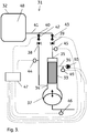
Figure 3 shows a perfusion system according to the invention with control valves, pressure transducers and control unit. -
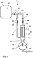
Figure 4 shows a perfusion system according to the invention, with aseptic connectors and unit housings. - In one aspect the present invention discloses a
system 1;31;51 for perfusion culture of cells. The system comprises: - a) at least one
bioreactor 2;32;52; - b) at least one
filter unit 3;33;53 which has aretentate inlet end 4;34;54, aretentate outlet end 5;35;55 and at least onepermeate outlet port 6;36;56 and; - c) at least one
reciprocating pump 7;37;57 which is fluidically connected to the retentate inlet end. - Further, the inlet and outlet check valves are each fluidically connected to a
tubing branch point 10;40;60, which is also connected to the bioreactor via a single length oftubing 11;41;61, e.g. a length of flexible tubing. Suitably, the connection between the tubing branch point and the bioreactor is via a single length of tubing. This is convenient as it minimizes the number of ports needed in the bioreactor and it reduces the complexity of the tubing package around the bioreactor. The latter is particularly important for moving bioreactors, e.g. of the rocking bag type, where the number of moving tubes needs to be kept at a minimum. An alternative possibility is however to have each of the theinlet 8;38;58 andoutlet 9;39;59 check valves fluidically connected to the bioreactor via separate lengths of tubing (not shown), without thebranch point 10;40;60. Separate tubing for inlet and outlet can ensure the favorable condition that liquid in tubing in between the bioreactor and the device is processed solely in a single pass regardless of the ratio between processed volume (difference between volume in inward and outward stroke of the pump) to the holdup volume in tubing in between bioreactor and device. Another alternative is to position the branch point at an intermediate position along the fluid connection between bioreactor and device, hereby accounting for process and hold up volumes and optimizing performance. - The bioreactor can suitably comprise a vessel with an
inner volume 12;48;62 and agitation means (not shown) located inside and/or outside the inner volume. The agitation means can e.g. be an impeller inside the inner volume, driven directly or magnetically by a motor outside the inner volume. The agitation means can also be a movable support on which the vessel is resting, which can convey a rocking and/or oscillatory movement to the vessel. - The filter unit can be a filter adapted for tangential flow filtration, e.g. a hollow fiber cartridge or a flat sheet cassette, with a plurality of membranes delimiting a retentate side and a permeate side. When the filter unit is a hollow fiber cartridge, as illustrated in
Figure 2 , the retentate inlet end can be adjacent and in connection with thefiber lumens 13 at one end of a hollow fiber bundle and the retentate outlet end can be adjacent and in connection with thefiber lumens 14 at the other end of the hollow fiber bundle. In this case, the permeate outlet port can be connected to the volume surrounding the shell side of thehollow fibers 24 in the bundle - thepermeate compartment 15, which volume is sealed off from the fiber lumens of the bundle. The filter unit can also comprise two permeate outlet ports, in which case it is possible to circulate the permeate along the fibers in the permeate compartment, suitably in a countercurrent (opposite) direction to the retentate circulation direction through the lumens. The filter unit can be contained in an elongated (e.g. cylindrical)housing 16 with the hollow fiber bundle located in the central part of the housing, andseals 17 delimiting thepermeate compartment 15 from aretentate inlet compartment 18 and aretentate outlet compartment 19. The retentate inlet compartment may be directly connected to the reciprocating pump at ajoint 20. - The reciprocating pump can suitably comprise a reciprocating moving
member 21, such as e.g. a diaphragm, a membrane or a piston. The reciprocating moving member can move back and forth in relation to a pump chamber 22 (also called a cylinder, when the moving member is a piston), forcing fluid (e.g. culture liquid) out from the pump chamber during an inward stroke of the moving member and sucking fluid (e.g. culture liquid) into the pump chamber during an outward stroke. The stroke volume of the reciprocating pump corresponds to the fluid (culture liquid) volume displaced out from or into the pump chamber during each stroke. The reciprocating pump may e.g. be a fluid-driven diaphragm pump as illustrated inFigs. 1-3 , with apump chamber 22 and a drive fluid-filleddrive chamber 23 separated by aflexible diaphragm 21, which constitutes the reciprocating moving member. The drive fluid can be a gas, e.g. air, or a liquid. When fluid pressure is applied to the drive chamber via a drivefluid supply line 25, the diaphragm expels liquid from the pump chamber in an inward stroke and when the fluid pressure is released, the diaphragm flexes back and draws liquid into the pump chamber in an outward stroke. The pump chamber may e.g. be directly connected to the retentate inlet compartment of the filter unit at a joint 20. Alternatively, it may be connected via a fluid connector (not shown), such as a short piece of tubing with a diameter large enough not to impede the liquid flow and a volume significantly smaller than the stroke volume of the reciprocating pump (e.g. less than 20% of the stroke volume, such as less than 10% or less than 5% of the stroke volume), optionally via an aseptic connector. - The connection between the retentate inlet end and the branch point, as well as between the retentate outlet end and the branch point can be achieved e.g. by tubing, such as flexible tubing, with the inlet and outlet check valves in-line with the tubing or adjacent the branch point or the inlet/outlet ends. The
branch point 10;40;60 may be e.g. a three-way tubing connector or a manifold. The connection between the branch point and the bioreactor may be a single line in the form of a length oftubing 11;41;61, such as flexible tubing. The tubing length may be connected to the inner volume of the bioreactor vessel through a port in the vessel wall. The inlet and outlet check valves may be of any suitable check valve type, e.g. flap, ball, slit disk valves etc. - During the outward stroke of the reciprocating pump, culture liquid will be drawn from the bioreactor via the length of
tubing branch point 10;40;60 to theretentate inlet end 4;34;54 of thefilter unit 3;33;53. At the same time, the outward stroke generates a negative pressure on the retentate side of the filter unit, which causes a certain amount of permeate to backflush the filter membrane and thus clean the membrane from clogged cells and other material. During the inward stroke of the reciprocating pump, culture liquid is pushed through the retentate side of the filter unit, producing permeate that can be withdrawn, and further via theretentate outlet end 5;35;55, thebranch point 10;40;60 and the length oftubing 11;41;61 back to the bioreactor. This flow routing has a number of advantages in comparison with the previously disclosed routings: - i) Possibility for individual pressure control during the inward and outward strokes. During the outward stroke, the negative pressure can be controlled to avoid outgassing and bubble formation and to optimize the backflushing. During the inward stroke, the transmembrane pressure over the filter unit can be optimized to maximize the mass transport over the filter membrane. The latter is particularly important when the filter unit comprises an ultrafiltration membrane for removal of metabolites as discussed below, but it is also important to reduce fouling and clogging when the filter unit comprises a microfiltration membrane. The individual control further allows for perfusion cultivation methods with minimal mechanical damage to cells and/or sensitive proteins, as well as for generally improving robustness and reproducibility.
- ii) The individual pressure control also provides possibility for new methods with combinations, variations and control of flows and pressures. One example is that an inlet control valve (as discussed below) can be used to throttle the flow to the retentate inlet end and in combination with a slow outward stroke of the reciprocating pump generate a very long backflush cycle.
- iii) The backflush becomes even and well-controlled due to the essentially constant pressure differential over the membrane during the outward stroke.
- iv) Scalability of the system is strongly improved as the pressures and pressure differentials over the membrane can be kept constant regardless of tubing diameters and lengths as well as the pressure inside the bioreactor and the hydrostatic pressure due to the vertical distance between the bioreactor and the filter unit.
- The construction materials used in the system can suitably be compatible with commonly used sterilization methods, such as e.g. gamma irradiation and/or autoclaving. For reusable components, stainless steel (e.g. with corrosion resistance at least equivalent to 316L) or engineering plastics such as polysulfone, PEEK etc may be used, while for single-use components, plastics, such as e.g. polysulfone, polypropylene, polyethylene or ethylene copolymers, may be used.
To avoid infection of the cell culture, the bioreactor and all components in contact with the culture fluid are suitable sterilized before cultivation. The system or parts of the system may be assembled and sterilized by autoclaving or radiation, or one or more components may be presterilized and assembled in a sterile system. To facilitate assembly, the sterilized system parts or components may be equipped with aseptic connectors, e.g. of the ReadyMate type (GE Healthcare). Alternatively, the sterilized system parts/components may be contained in aseptic packages and assembled in a sterile clean room. - In some embodiments, the length of
tubing 11;41;61 has an inner volume lower than or equal to 50%, such as lower than or equal to 20% or 10%, of the stroke volume of the reciprocating pump. This has the advantage that a major part of the stroke volume is utilized for transport of liquid from the bioreactor and back via the filter unit. - In some embodiments, the permeate outlet port 36 is connected to a permeate pump 50. The permeate pump can be used to withdraw permeate from the filter unit and can also be utilized for control of the transmembrane pressure in the filter unit. The permeate pump may e.g. be a peristaltic pump. The permeate pump 50 can be arranged to operate in two flow directions, e.g. in a forward direction conveying permeate from the permeate outlet to a storage or waste vessel (not shown) or to further processing operations (not shown) and in a backward direction for backflushing the filter membrane with permeate.
- In certain embodiments, illustrated by
Figs. 3 and4 , the system comprises aninlet control valve 42;63 between theretentate inlet end 34;54 and thebranch point 40;60. It can be located either between the retentate inlet end and the inlet check valve or between the inlet check valve and the branch point. It can also form an integrated part of the inlet check valve. The inlet control valve can suitably be capable of adjusting the flow and/or the pressure drop over the fluid connection between the bioreactor and the retentate inlet end. - In some embodiments, illustrated by
Figs. 3 and4 , the system comprises anoutlet control valve 43;64 between theretentate outlet end 35;55 and thebranch point 40;60. It can be located either between the retentate outlet end and the retentate outlet check valve or between the retentate outlet check valve and the branch point. It can also form an integrated part of the outlet check valve or one or more check valve(s) may be combined with one or more control valve(s) in an integrated valve block. The outlet control valve can suitably be capable of adjusting the flow and/or the pressure drop over the fluid connection between the retentate outlet end and the bioreactor. The inlet and outlet control valves can be any type of valve suitable for adjusting liquid flow and they can also be clamping devices applied on the outside of flexible tubing, e.g. pinch valves, hose closure clamps etc. The control valves can be either manually adjustable or arranged to be adjustable according to signals transmitted from a control unit. Such signals can e.g. be of electrical, electromagnetic, optical or pneumatic character. - In certain embodiments, illustrated by
Fig. 3 , the system comprises aninlet pressure transducer 44 arranged to measure the pressure at the retentate inlet end. This pressure transducer can be located at the retentate inlet end of thefilter unit 33 or at any point between the retentate inlet end and the inlet control valve. In embodiments without inlet control valve, it can be located at any point between the retentate inlet end and the branch point. The system can also (or alternatively) comprise anoutlet pressure transducer 45 arranged to measure the pressure at the retentate outlet end. This pressure transducer can be located at the retentate outlet end of thefilter unit 33 or at any point between the retentate outlet end and the outlet control valve. In embodiments without outlet control valve, it can be located at any point between the retentate outlet end and the branch point. The pressure transducers can be either manually readable manometers or transducers arranged to transmit pressure data to a control unit, e.g. by electrical, electromagnetic or optical means. Theoutlet pressure transducer 45 can e.g. be employed for an exact determination of the transmembrane pressure over the filter unit and membrane, respectively. - In some embodiments, the permeate outlet port 36 comprises a
permeate pressure transducer 49. The permeate pressure transducer can be capable of measuring the pressure on the permeate side of the filter unit, which in combination with data from the inlet and/or outlet pressure transducers can be used to calculate the transmembrane pressure over the filter unit. The permeate pressure transducer can also be used in a feedback loop for control of the transmembrane pressure by the operation of the permeate pump 50 or by some other permeate pressure control means (e.g. hydrostatic pressure control).Transducer 49 is also useful for control of the backflush cycle during the outward stroke of the reciprocating pump. - In some embodiments, illustrated by
Fig. 3 , thereciprocating pump 37 is a fluid-driven diaphragm pump and the system comprises a drivefluid pressure transducer 46 arranged to measure the drive fluid pressure in the reciprocating pump, mounted e.g. in the drive fluid supply line. The drive fluid pressure transducer can be either a manually readable manometer or a transducer arranged to transmit pressure data to a control unit, e.g. by electrical, electromagnetic or optical means. The drive fluid can be a gas (e.g. air) or a liquid. - In certain embodiments, the
reciprocating pump 37 is a gas-driven diaphragm pump and the system comprises agas pressure transducer 46 arranged to measure the gas pressure in the pump, mounted e.g. in the gas supply line. The gas can in particular be air, in which case the gas (drive fluid) supply is a source of compressed air. - In some embodiments, the
reciprocating pump 7;37;57 is designed as a diaphragm pump with a highly flexible diaphragm, e.g. a soft silicone rubber diaphragm, hereby reducing mechanical energy loss between the reciprocating pump at the side of the fluid supply line towards the side of thefilter unit 3;33;53 and itsretentate inlet end 4;34;54. Hereby, the pressure at the inlet side of thefilter unit 33 will be equal to the pressure measured at the pressure transducer at the side of thefluid supply line 46. Thus, the fluid pressure of the bioreactor fluid at the side of the retentate inlet, and hereby the filtration process and the transmembrane pressure, can effectively be measured and controlled by employing the drivefluid pressure transducer 46, which is not in contact with the bioreactor fluid. This design gives advantages when designing a system with single-use components in contact with the bioreactor fluid. It reduces cost and complexity as the drivefluid pressure transducer 46 can be re-usable and does not need to be sterilized. Hence also non-sterilizable high performance sensors can be used and if a sterilizable high performance sensor is used it does not need to be recalibrated after sterilization. - In certain embodiments, illustrated by
Fig. 3 , the system comprises at least onecontrol unit 47, arranged to control at least one of the reciprocating pump and the inlet and outlet control valves depending on pressure data received from at least one of the inlet and outlet pressure transducers. The control unit(s) can suitably be electrically, electromagnetically (e.g. by wireless communication), optically (e.g. via optical fibers) or pneumatically connected to at least one of the reciprocating pump and the inlet and outlet control valves and to at least one of the inlet and outlet pressure transducers. The control unit(s) can be e.g. a computer, a programmable logic controller or any similar device capable of a) receiving input signals from one or more pressure transducers, b) calculating one or more output parameters from the input signals according to a predetermined method and c) transmitting the output parameter(s) as a signal/signals to one or more control valves and/or a pump. The control unit can be one integrated control unit, arranged to control both the reciprocating pump and the inlet and/or the outlet control valve or the system may comprise a main control unit (or a valve control unit) and a pump control unit (not shown). The pump control unit may e.g. be arranged to control the flow and pressure profile generated by the reciprocating pump via one or more of the stroke frequency, the stroke length and the velocity of the moving member during the inward and outward strokes. In the case of a fluid driven diaphragm pump, the stroke frequency, the stroke length and the diaphragm velocity can be controlled e.g. via one or more valves on the drive fluid supply line. As noted above, the features of the pump control unit can also be integrated into a main control unit, or- vice versa - the control valve(s) may also be controlled by an integrated pump control unit. Alternatively, the control valve(s) can be preset or manually adjusted, such that only a pump control unit is needed. - The control unit may also be connected to the permeate pump 50 and/or the
permeate pressure transducer 49 for control of the transmembrane pressure. - In some embodiments the filter unit is a hollow fiber cartridge or a flat sheet cassette. Hollow fiber cartridges have been described above, but it is also possible to use a flat sheet cassette of the conventional tangential flow filtration type. In this case, the retentate inlet apertures correspond to the fiber lumen ends on the retentate inlet side, the retentate outlet apertures to the lumen ends on the retentate outlet side and the permeate apertures to the permeate outlet.
- In certain embodiments the bioreactor comprises an inflatable flexible bag, resting on a movable support, and the length of
tubing 11;41;61 is a flexible length of tubing. The system of the invention is particularly suitable for bioreactors which are agitated by moving the entire bioreactor vessel (i.e. the inflatable flexible bag), since only one length of tubing is needed to connect to the bioreactor, which keeps the number of moving connections to the vessel low and reduces entangling of these. - In some embodiments, the system is partially or entirely composed of single-use components, which can suitable be presterilized e.g. by gamma irradiation or autoclaving and then connected together using aseptic connectors, such as e.g. ReadyMate (GE Healthcare). One example of such a
system 51 is illustrated inFig. 4 , withaseptic connectors 65 and connectors which may or may not be aseptic 66. As indicated inFig 4 . it is also possible to contain thefilter unit 53,check valves control valves outer housing 67. It is also possible to contain thereciprocating pump 57 in the same housing or in aseparate housing 68. Thereciprocating pump 57 may be single-use or reusable and it may even be assembled from a single use part comprising the pump chamber and the diaphragm and a reusable part comprising the drive chamber and the drive fluid supply line with the drive fluid pressure transducer. The single use part of the reciprocating pump may in this case also be integrated with the filter unit. - Although the figures show the
reciprocating pump 7;37;57 placed below thefilter unit 3;33;53, other orientations are equally possible, e.g. by placing the reciprocating pump above the filter unit. The particular orientation can depend e.g. on space and distance considerations as well as utilization of hydrostatic pressures for different purposes. - In a second aspect the present invention discloses a method for perfusion culture of cells, comprising the steps of:
- a) providing a
system 1;31;51 as described above; - b) adding cell culture medium and cells to the
bioreactor 2;32;52; - c) cultivating cells in the bioreactor under agitation;
- d) during cultivation operating the
reciprocating pump 7;37;57 to i) withdraw fluid from the bioreactor via the length oftubing 11;41;61, thebranch point 10;40;60 and theinlet check valve 8;38;58 to theretentate inlet end 4;34;54 of thefilter unit 3;33;53 and to ii) return fluid from theretentate outlet end 5;35;55 of the filter unit via theoutlet check valve 9;39;59, thebranch point 10;40;60 and the length oftubing 11;41;61 to thebioreactor 2;32;52 and; - e) withdrawing a permeate from the
permeate outlet port 6;36;56. - In some embodiments the method comprises adding at least one fluid, such as a cell culture medium, to the bioreactor during cultivation. This has the advantage that culture liquid removed via the filter unit can be replenished and that fresh nutrients and other reagents can be supplied to the culture.
- In certain embodiments the filter unit comprises a microfiltration membrane and the permeate comprises a target substance expressed by the cells. This allows for continuous harvest of the target substance, which can be e.g. a protein such as an immunoglobulin.
In some embodiments the filter unit comprises an ultrafiltration membrane and a target substance expressed by the cells is retained in the retentate and returned to the bioreactor. This allows for continuous removal of toxic or otherwise undesirable low molecular weight waste products/metabolites from the cell culture, while the target substance, e.g. a protein such as an immunoglobulin, can be harvested from the culture at the end of the cultivation. - In certain embodiments the method comprises controlling at least one of the reciprocating pump and the inlet control valve to keep the pressure reading from the inlet pressure transducer within a preset range during the outward strokes of the reciprocating pump. The controlling may be achieved either manually, e.g. from a manometer reading by manual adjustment of the valve or by a control unit according to signals received from the pressure transducer. The advantage of this method is that the backflushing of the filter unit due to the negative pressure generated by the outward stroke can be controlled and optimized to give an efficient cleaning of the membrane and optionally a minimal dilution of the retentate with backflushed permeate. It is also possible to control the pressure according to more complex algorithms, e.g. producing desirable pressure versus time profiles during the outward strokes.
- In some embodiments the method comprises calculating a transmembrane pressure from data provided by the inlet and outlet pressure transducers or from at least one of the inlet and outlet pressure transducers and the permeate pressure transducer and controlling at least one of the reciprocating pump, the permeate pump and the inlet and outlet control valves to keep the transmembrane pressure between preset upper and lower limits. This has the advantage that mass transport across the filter membrane can be maximized and fouling and concentration polarization can be minimized. It is also possible to control the pressure according to more complex algorithms, e.g. producing desirable transmembrane pressure versus time profiles during both the outward and inward strokes.
- In some embodiments the method comprises keeping the transmembrane pressure within a first range during the outward stroke of the reciprocating pump and within a second range during the inward stroke of the reciprocating pump.
- In certain embodiments the method comprises operating the permeate pump 50 in a backward direction to produce a backflush of the filter membrane. The permeate pump may be the sole source of the backflush or the permeate pump may be thus operated during the outward stroke of the reciprocating pump to assist in the bacflush and to create desirable pressure/flow profiles during the backflush cycle. The permeate pump may be controlled by the one or
more control units 47, according to input data from e.g. thepermeate pressure transducer 49. - When the system is composed of single-use components, it is economically feasible to discard all the components after use. The system described above is particularly suitable for single-use application, but it is also possible to use conventional alternating tangential flow systems in a single-use mode.
- The description further discloses a pre-sterilized system for perfusion culture of cells, which comprises:
- a) at least one bioreactor (2;32;52);
- b) at least one reciprocating pump (7;37;57)
- c) at least one filter unit (3) fluidically connected to the reciprocating pump and fluidically connected to the bioreactor via at least one aseptic connector.
- The pre-sterilized system can be assembled from at least two pre-sterilized modules via one or more aseptic connectors. A pre-sterilized single-use alternating tangential flow filtration system may be assembled at the point of use from pre-sterilized single-use modules building such a system by using aseptic connectors at respective interfaces in between the modules, compare
Fig 4 . Hereby, higher flexibility is achieved in sizing the capacity of the pre-sterilized single-use alternating tangential flow filtration system by selecting and assembling filter size and pump size or other components to match the capacity and performance suitable to the bioreactor and process to be served.
Claims (15)
- A system (1;31;51) for perfusion culture of cells comprising:a) at least one bioreactor (2;32;52);b) at least one filter unit (3) comprising a retentate inlet end (4;34;54), a retentate outlet end (5) and at least one permeate outlet port (6;36;56);c) at least one reciprocating pump (7;37;57) fluidically connected to the retentate inlet end, wherein said retentate inlet end is fluidically connected to said bioreactor via an inlet check valve (8;38;58) arranged to allow flow in the direction from the bioreactor to the retentate inlet end and to block flow in the reverse direction, and wherein said retentate outlet end is fluidically connected to said bioreactor via an outlet check valve (9;39;59) arranged to allow flow in the direction from the retentate outlet end to the bioreactor and to block flow in the reverse direction; andwherein said inlet and outlet check valves are each fluidically connected to a tubing branch point (10;40;60), which is further connected to the bioreactor via a single length of tubing (11;41;61).
- The system according to claim 1, wherein said reciprocating pump is a diaphragm pump, such as a fluid-driven diaphragm pump and wherein the system optionally comprises a drive fluid pressure transducer (46) arranged to measure a drive fluid pressure in the reciprocating pump (37).
- The system of claim 1 or 2, wherein said length of tubing (11;41;61) has an inner volume lower than or equal to 50%, such as lower than or equal to 25% or 10%, of the stroke volume of the reciprocating pump.
- The system according to any preceding claim, further comprising an inlet control valve (42;63) between said inlet check valve (8;38;58) and said branch point (10;40;60) and/or an outlet control valve (43;64) between said outlet check valve (9;39;59) and said branch point (10;40;60).
- The system according to any preceding claim, further comprising an inlet pressure transducer (44) arranged to measure the pressure at said retentate inlet end and optionally an outlet pressure transducer (45) arranged to measure the pressure at said retentate outlet end.
- The system according to any one of claims 4 - 5, further comprising at least one control unit (47), arranged to control at least one of the reciprocating pump (37) and the inlet (42) and outlet (43) control valves depending on pressure data received from at least one of said inlet (44) and outlet (45) pressure transducers and wherein the control unit(s) optionally is/are arranged to control at least one of the inlet control valve and the reciprocating pump depending on pressure data received from said inlet pressure transducer.
- The system according to any preceding claim, further comprising a permeate pump (50) and a permeate pressure transducer (49), optionally connected to at least one control unit (47).
- The system according to any preceding claim, wherein said filter unit comprises a microfiltration or ultrafiltration membrane and/or wherein said filter unit is a hollow fiber cartridge or a flat sheet cassette.
- The system of any one of claims 1-8, assembled from at least two pre-sterilized modules via one or more aseptic connectors and/or partly or entirely composed of single-use components.
- A method for perfusion culture of cells, comprising the steps of:a) providing a system (1;31;51) according to any preceding claim;b) adding cell culture medium and cells to said bioreactor (2;32;52);c) cultivating cells in said bioreactor under agitation;d) during cultivation operating said reciprocating pump (7;37;57) to i) withdraw fluid from said bioreactor via said single length of tubing (11;41;61), said branch point (10;40;60) and said inlet check valve (8;38;58) to said retentate inlet end (4;34;54) of said filter unit (3;33;53) and to ii) return fluid from said retentate outlet end (5;35;55) of said filter unit via said outlet check valve (9;39;59), said branch point (10;40;60) and said single length of tubing (11;41;61) to said bioreactor (2;32;52) and;e) withdrawing a permeate from said permeate outlet port (6;36;56).
- The method according to claim 10, further comprising adding at least one fluid, such as a cell culture medium to the bioreactor during cultivation.
- The method according to claim 10 or 11, wherein the filter unit comprises a microfiltration membrane and wherein the permeate comprises a target substance expressed by the cells or wherein the filter unit comprises an ultrafiltration membrane and wherein a target substance expressed by the cells is retained in the retentate and returned to the bioreactor.
- The method according to any one of claims 10-12, further comprising i) controlling at least one of the reciprocating pump (37;57) and the inlet control valve (42;63) to keep the pressure reading from the inlet pressure transducer (44) within a preset range during the outward strokes of the reciprocating pump (37;57) and/or ii) calculating a transmembrane pressure from data provided by the inlet (44) and outlet (45) pressure transducers and controlling the reciprocating pump (57) and/or at least one of the inlet (42) and outlet (43) control valves to keep the transmembrane pressure between preset upper and lower limits.
- The method according to claim 13, wherein the transmembrane pressure is kept within a first range during the outward stroke of the reciprocating pump (57) and within a second range during the inward stroke of the reciprocating pump.
- The method according to any one of claims 10-14, further comprising operating the permeate pump (50) in a backward direction to produce a backflush of the filter membrane, optionally controlled by the control unit (47) using input data from the permeate pressure transducer (49).
Applications Claiming Priority (2)
| Application Number | Priority Date | Filing Date | Title |
|---|---|---|---|
| SE1251091 | 2012-09-27 | ||
| PCT/SE2013/051110 WO2014051503A1 (en) | 2012-09-27 | 2013-09-25 | Tangential flow perfusion system |
Publications (3)
| Publication Number | Publication Date |
|---|---|
| EP2900804A1 EP2900804A1 (en) | 2015-08-05 |
| EP2900804A4 EP2900804A4 (en) | 2015-10-07 |
| EP2900804B1 true EP2900804B1 (en) | 2019-09-18 |
Family
ID=50388729
Family Applications (1)
| Application Number | Title | Priority Date | Filing Date |
|---|---|---|---|
| EP13840366.2A Active EP2900804B1 (en) | 2012-09-27 | 2013-09-25 | Tangential flow perfusion system |
Country Status (6)
| Country | Link |
|---|---|
| US (1) | US9663753B2 (en) |
| EP (1) | EP2900804B1 (en) |
| JP (1) | JP6321661B2 (en) |
| CN (2) | CN104640973A (en) |
| IN (1) | IN2015DN01067A (en) |
| WO (1) | WO2014051503A1 (en) |
Families Citing this family (43)
| Publication number | Priority date | Publication date | Assignee | Title |
|---|---|---|---|---|
| US10711238B2 (en) | 2012-10-02 | 2020-07-14 | Repligen Corporation | Method for proliferation of cells within a bioreactor using a disposable pumphead and filter assembly |
| HUE055888T2 (en) | 2013-09-16 | 2022-01-28 | Genzyme Corp | Methods and systems for processing a cell culture |
| JP6530171B2 (en) * | 2014-09-09 | 2019-06-12 | 旭化成メディカル株式会社 | Method of collecting culture product |
| EP3215261B1 (en) * | 2014-11-07 | 2021-12-15 | Genesis Technologies, LLC | Linear reciprocating actuator |
| CN108350405A (en) * | 2015-08-08 | 2018-07-31 | 施托贝制药技术股份有限公司 | The active disposable biological processing system of biological support |
| US20180221823A1 (en) | 2015-08-20 | 2018-08-09 | Ge Healthcare Bio-Sciences Ab | Re-Circulation Loop in CFF/TFF Single Use Path Flow |
| EP3374636B1 (en) * | 2015-11-10 | 2020-06-03 | Repligen Corporation | Disposable alternating tangential flow filtration units |
| EP3386613A1 (en) | 2015-12-07 | 2018-10-17 | GE Healthcare Bio-Sciences AB | Unit for treatment of a bioprocess liquid with disposable flow path elements |
| ITUB20160272A1 (en) * | 2016-01-22 | 2017-07-22 | Univ Degli Studi Di Palermo | Disposable self-sufficient perfusion bioreactor for 3D cell growths |
| WO2017144440A2 (en) * | 2016-02-26 | 2017-08-31 | Ge Healthcare Bio-Sciences Ab | Method for pressure control in crossflow filtration |
| CN105950468B (en) * | 2016-05-23 | 2018-03-02 | 西安交通大学 | A kind of bioreactor for perfusion and the bioreactor for infiltration |
| EP3487977B1 (en) | 2016-07-19 | 2022-09-14 | The Automation Partnership (Cambridge) Limited | Reversible liquid filtration system |
| CN109415673B (en) * | 2016-07-19 | 2022-09-06 | 自动化合作关系(剑桥)有限公司 | Liquid filtration and pump system |
| JP6890389B2 (en) * | 2016-08-29 | 2021-06-18 | 株式会社日立製作所 | Liquid transfer device and cell culture device using it |
| DK179641B1 (en) * | 2017-02-10 | 2019-03-06 | Sani Membranes Aps | Vibrating filter plate assembly device |
| TWI675696B (en) | 2017-06-01 | 2019-11-01 | 美商Emd密理博公司 | Tangential flow filtration device for perfusion applications |
| US10774297B2 (en) * | 2017-08-03 | 2020-09-15 | Repligen Corporation | Method of actuation of an alternating tangential flow diaphragm pump |
| CN111770986A (en) * | 2017-09-27 | 2020-10-13 | 尤尼沃尔塞尔斯股份公司 | System and method for preparing biomolecules (e.g., viral vaccines) |
| WO2019084410A1 (en) | 2017-10-26 | 2019-05-02 | Repligen Corporation | Micro alternating tangential flow perfusion filter, process vessel, and methods of use thereof |
| US10792594B2 (en) * | 2017-12-28 | 2020-10-06 | Replegin Corporation | Dual pumping arrangement for a hollow fiber filter |
| CN111565823B (en) * | 2018-01-12 | 2023-03-31 | 富默乐有限公司 | Tangential flow filtration TFF system and disposable TFF unit including integrated pump device |
| US11932842B2 (en) | 2018-02-09 | 2024-03-19 | Global Life Sciences Solutions Usa Llc | Bioprocessing apparatus |
| WO2019155028A1 (en) * | 2018-02-09 | 2019-08-15 | General Electric Company | Bioprocessing methods for cell therapy |
| US11920119B2 (en) | 2018-02-09 | 2024-03-05 | Global Life Sciences Solutions Usa Llc | Systems and methods for bioprocessing |
| KR20200106960A (en) * | 2018-02-27 | 2020-09-15 | 미쓰비시덴키 가부시키가이샤 | Aeration amount control system and aeration amount control method |
| JP2021531767A (en) * | 2018-07-27 | 2021-11-25 | ユニバーセルズ テクノロジーズ エス.エー.Univercells Technologies S.A. | Systems and methods for producing biomolecules |
| EP3843884A1 (en) * | 2018-08-29 | 2021-07-07 | Cytiva Sweden AB | System for filtration and associated method thereof |
| GB201816897D0 (en) * | 2018-10-17 | 2018-11-28 | Ge Healthcare Bio Sciences Corp | A Bioreactor System |
| CN109735448A (en) * | 2019-02-02 | 2019-05-10 | 上海天引生物科技有限公司 | A kind of cells in vitro hydrodynamic shear stimulation culture apparatus and its method |
| EP3914690A4 (en) * | 2019-02-08 | 2022-11-09 | Lonza Walkersville, Inc. | Cell concentration methods and devices for use in automated bioreactors |
| US20220213420A1 (en) * | 2019-05-02 | 2022-07-07 | Global Life Sciences Solutions Usa Llc | Bioprocessing system and consumable bag for a bioprocessing system |
| GB201908612D0 (en) * | 2019-06-17 | 2019-07-31 | Ge Healthcare Bio Sciences Ab | A method for separating biomolecules |
| US11524262B2 (en) | 2019-08-05 | 2022-12-13 | Repligen Corporation | Devices, systems, and methods for continuous processing with alternating tangential flow |
| SK289034B6 (en) * | 2019-10-10 | 2023-01-25 | EKOM spol. s r. o. | A membrane gas separator with a built-in valve and the method of its opening and closing |
| CN111534411A (en) * | 2020-04-03 | 2020-08-14 | 利穗科技(苏州)有限公司 | Alternate tangential flow canning culture device and control method thereof |
| CN112322496B (en) * | 2021-01-05 | 2021-04-23 | 北京百普赛斯生物科技股份有限公司 | Perfusion production system and method for new coronavirus S1 protein |
| EP4313356A2 (en) | 2021-04-16 | 2024-02-07 | Repligen Corporation | Filtration system and method |
| JP2022182361A (en) * | 2021-05-28 | 2022-12-08 | ダイセン・メンブレン・システムズ株式会社 | Separating/purifying method and separating/purifying apparatus of micro useful substance |
| JP2022182360A (en) * | 2021-05-28 | 2022-12-08 | ダイセン・メンブレン・システムズ株式会社 | Separating/purifying method of extracellular vesicles |
| CN113265330B (en) * | 2021-06-04 | 2022-04-01 | 河南大学 | Animal cell high-density culture system suitable for efficient production of vaccines and antibodies |
| CN114107045B (en) * | 2021-10-12 | 2023-08-11 | 江苏蒙彼利生物科技有限公司 | Serum-free stem cell culture perfusion device and perfusion method |
| WO2024024337A1 (en) * | 2022-07-28 | 2024-02-01 | 株式会社ダイセル | Device for purifying and concentrating liquid that contains minute useful substance, and method for producing purified concentrate that contains minute useful substance using said device |
| WO2024054423A1 (en) * | 2022-09-06 | 2024-03-14 | Amgen Inc. | Large scale bioreactor system and method |
Family Cites Families (11)
| Publication number | Priority date | Publication date | Assignee | Title |
|---|---|---|---|---|
| US2004425A (en) | 1933-04-05 | 1935-06-11 | William H Bain | Shoe and process of making same |
| JPH0775536B2 (en) * | 1986-03-26 | 1995-08-16 | 猛 小林 | Enzyme production equipment using genetically modified bacteria |
| US6544424B1 (en) * | 1999-12-03 | 2003-04-08 | Refined Technology Company | Fluid filtration system |
| US6511124B2 (en) | 2001-01-23 | 2003-01-28 | Mark Ellis Combs | Tray table for a child's car seat and associated methods |
| EP1354941A1 (en) | 2002-04-19 | 2003-10-22 | Computer Cell Culture Center S.A. | Apparatus and method for a cell culture in a bioreactor at high cell concentration |
| AU2003238273A1 (en) * | 2003-06-17 | 2005-02-04 | Centocor, Inc. | Method and apparatus for filtration of bioreactor recombinant proteins |
| US7875448B2 (en) * | 2004-01-12 | 2011-01-25 | Single Use Brx, Llc | Bioreactor systems and disposable bioreactor |
| CN104593277A (en) | 2004-03-05 | 2015-05-06 | 帝斯曼知识产权资产管理有限公司 | Process for cell culturing by continuous perfusion and alternating tangential flow |
| EP2188371B1 (en) * | 2007-08-09 | 2017-12-20 | Wyeth LLC | Use of perfusion to enhance production of fed-batch cell culture in bioreactors |
| CA2807768A1 (en) | 2010-08-25 | 2012-03-01 | Jerry Shevitz | Enclosed filtration system with three chambers |
| JP5978995B2 (en) | 2010-12-09 | 2016-08-24 | 東レ株式会社 | Process for producing chemicals by continuous fermentation |
-
2013
- 2013-09-25 CN CN201380050422.3A patent/CN104640973A/en active Pending
- 2013-09-25 US US14/430,346 patent/US9663753B2/en active Active
- 2013-09-25 EP EP13840366.2A patent/EP2900804B1/en active Active
- 2013-09-25 JP JP2015534432A patent/JP6321661B2/en active Active
- 2013-09-25 WO PCT/SE2013/051110 patent/WO2014051503A1/en active Application Filing
- 2013-09-25 CN CN201811359986.6A patent/CN110066730A/en active Pending
-
2015
- 2015-02-10 IN IN1067DEN2015 patent/IN2015DN01067A/en unknown
Non-Patent Citations (1)
| Title |
|---|
| None * |
Also Published As
| Publication number | Publication date |
|---|---|
| CN110066730A (en) | 2019-07-30 |
| WO2014051503A1 (en) | 2014-04-03 |
| US9663753B2 (en) | 2017-05-30 |
| IN2015DN01067A (en) | 2015-06-26 |
| EP2900804A1 (en) | 2015-08-05 |
| EP2900804A4 (en) | 2015-10-07 |
| CN104640973A (en) | 2015-05-20 |
| US20150247114A1 (en) | 2015-09-03 |
| JP6321661B2 (en) | 2018-05-09 |
| JP2015530110A (en) | 2015-10-15 |
Similar Documents
| Publication | Publication Date | Title |
|---|---|---|
| EP2900804B1 (en) | Tangential flow perfusion system | |
| US20220098539A1 (en) | Enclosed filtration and bioreactor systems and processes | |
| EP3041927B1 (en) | Cell culture bag with internal dialysis membrane | |
| US20180236407A1 (en) | Fluid Filtration Systems | |
| US7919307B2 (en) | Supply system for cell culture module | |
| US7875448B2 (en) | Bioreactor systems and disposable bioreactor | |
| US8845902B2 (en) | Pneumatic alternating pressure membrane cell separation system | |
| KR20230156168A (en) | Disposable bioprocess system supporting biological activity | |
| EP2379692A2 (en) | Biopharmaceutical plant in a column | |
| US20190240622A1 (en) | Single-use process vessel with integrated filter module | |
| KR20230022179A (en) | Smart Tanks for Biopharmaceutical Processing | |
| KR20080018161A (en) | Apparatus for providing media to cell culture modules |
Legal Events
| Date | Code | Title | Description |
|---|---|---|---|
| PUAI | Public reference made under article 153(3) epc to a published international application that has entered the european phase |
Free format text: ORIGINAL CODE: 0009012 |
|
| 17P | Request for examination filed |
Effective date: 20150330 |
|
| AK | Designated contracting states |
Kind code of ref document: A1 Designated state(s): AL AT BE BG CH CY CZ DE DK EE ES FI FR GB GR HR HU IE IS IT LI LT LU LV MC MK MT NL NO PL PT RO RS SE SI SK SM TR |
|
| AX | Request for extension of the european patent |
Extension state: BA ME |
|
| RA4 | Supplementary search report drawn up and despatched (corrected) |
Effective date: 20150907 |
|
| RIC1 | Information provided on ipc code assigned before grant |
Ipc: C12M 3/06 20060101AFI20150901BHEP Ipc: C12M 1/34 20060101ALI20150901BHEP Ipc: F16K 15/00 20060101ALI20150901BHEP Ipc: C12M 1/00 20060101ALI20150901BHEP |
|
| DAX | Request for extension of the european patent (deleted) | ||
| STAA | Information on the status of an ep patent application or granted ep patent |
Free format text: STATUS: EXAMINATION IS IN PROGRESS |
|
| 17Q | First examination report despatched |
Effective date: 20180124 |
|
| REG | Reference to a national code |
Ref country code: DE Ref legal event code: R079 Ref document number: 602013060769 Country of ref document: DE Free format text: PREVIOUS MAIN CLASS: C12M0003060000 Ipc: B01D0061180000 |
|
| GRAP | Despatch of communication of intention to grant a patent |
Free format text: ORIGINAL CODE: EPIDOSNIGR1 |
|
| STAA | Information on the status of an ep patent application or granted ep patent |
Free format text: STATUS: GRANT OF PATENT IS INTENDED |
|
| RIC1 | Information provided on ipc code assigned before grant |
Ipc: B01D 61/18 20060101AFI20190326BHEP Ipc: C12M 1/00 20060101ALI20190326BHEP Ipc: C12M 1/34 20060101ALI20190326BHEP Ipc: B01D 63/02 20060101ALI20190326BHEP Ipc: B01D 63/08 20060101ALI20190326BHEP |
|
| INTG | Intention to grant announced |
Effective date: 20190411 |
|
| GRAS | Grant fee paid |
Free format text: ORIGINAL CODE: EPIDOSNIGR3 |
|
| GRAA | (expected) grant |
Free format text: ORIGINAL CODE: 0009210 |
|
| STAA | Information on the status of an ep patent application or granted ep patent |
Free format text: STATUS: THE PATENT HAS BEEN GRANTED |
|
| AK | Designated contracting states |
Kind code of ref document: B1 Designated state(s): AL AT BE BG CH CY CZ DE DK EE ES FI FR GB GR HR HU IE IS IT LI LT LU LV MC MK MT NL NO PL PT RO RS SE SI SK SM TR |
|
| REG | Reference to a national code |
Ref country code: GB Ref legal event code: FG4D |
|
| REG | Reference to a national code |
Ref country code: CH Ref legal event code: EP |
|
| REG | Reference to a national code |
Ref country code: DE Ref legal event code: R096 Ref document number: 602013060769 Country of ref document: DE |
|
| REG | Reference to a national code |
Ref country code: AT Ref legal event code: REF Ref document number: 1180654 Country of ref document: AT Kind code of ref document: T Effective date: 20191015 |
|
| REG | Reference to a national code |
Ref country code: IE Ref legal event code: FG4D |
|
| REG | Reference to a national code |
Ref country code: NL Ref legal event code: MP Effective date: 20190918 |
|
| PG25 | Lapsed in a contracting state [announced via postgrant information from national office to epo] |
Ref country code: LT Free format text: LAPSE BECAUSE OF FAILURE TO SUBMIT A TRANSLATION OF THE DESCRIPTION OR TO PAY THE FEE WITHIN THE PRESCRIBED TIME-LIMIT Effective date: 20190918 Ref country code: HR Free format text: LAPSE BECAUSE OF FAILURE TO SUBMIT A TRANSLATION OF THE DESCRIPTION OR TO PAY THE FEE WITHIN THE PRESCRIBED TIME-LIMIT Effective date: 20190918 Ref country code: BG Free format text: LAPSE BECAUSE OF FAILURE TO SUBMIT A TRANSLATION OF THE DESCRIPTION OR TO PAY THE FEE WITHIN THE PRESCRIBED TIME-LIMIT Effective date: 20191218 Ref country code: SE Free format text: LAPSE BECAUSE OF FAILURE TO SUBMIT A TRANSLATION OF THE DESCRIPTION OR TO PAY THE FEE WITHIN THE PRESCRIBED TIME-LIMIT Effective date: 20190918 Ref country code: FI Free format text: LAPSE BECAUSE OF FAILURE TO SUBMIT A TRANSLATION OF THE DESCRIPTION OR TO PAY THE FEE WITHIN THE PRESCRIBED TIME-LIMIT Effective date: 20190918 Ref country code: NO Free format text: LAPSE BECAUSE OF FAILURE TO SUBMIT A TRANSLATION OF THE DESCRIPTION OR TO PAY THE FEE WITHIN THE PRESCRIBED TIME-LIMIT Effective date: 20191218 |
|
| REG | Reference to a national code |
Ref country code: LT Ref legal event code: MG4D |
|
| PG25 | Lapsed in a contracting state [announced via postgrant information from national office to epo] |
Ref country code: RS Free format text: LAPSE BECAUSE OF FAILURE TO SUBMIT A TRANSLATION OF THE DESCRIPTION OR TO PAY THE FEE WITHIN THE PRESCRIBED TIME-LIMIT Effective date: 20190918 Ref country code: LV Free format text: LAPSE BECAUSE OF FAILURE TO SUBMIT A TRANSLATION OF THE DESCRIPTION OR TO PAY THE FEE WITHIN THE PRESCRIBED TIME-LIMIT Effective date: 20190918 Ref country code: GR Free format text: LAPSE BECAUSE OF FAILURE TO SUBMIT A TRANSLATION OF THE DESCRIPTION OR TO PAY THE FEE WITHIN THE PRESCRIBED TIME-LIMIT Effective date: 20191219 Ref country code: AL Free format text: LAPSE BECAUSE OF FAILURE TO SUBMIT A TRANSLATION OF THE DESCRIPTION OR TO PAY THE FEE WITHIN THE PRESCRIBED TIME-LIMIT Effective date: 20190918 |
|
| REG | Reference to a national code |
Ref country code: AT Ref legal event code: MK05 Ref document number: 1180654 Country of ref document: AT Kind code of ref document: T Effective date: 20190918 |
|
| PG25 | Lapsed in a contracting state [announced via postgrant information from national office to epo] |
Ref country code: IT Free format text: LAPSE BECAUSE OF FAILURE TO SUBMIT A TRANSLATION OF THE DESCRIPTION OR TO PAY THE FEE WITHIN THE PRESCRIBED TIME-LIMIT Effective date: 20190918 Ref country code: EE Free format text: LAPSE BECAUSE OF FAILURE TO SUBMIT A TRANSLATION OF THE DESCRIPTION OR TO PAY THE FEE WITHIN THE PRESCRIBED TIME-LIMIT Effective date: 20190918 Ref country code: NL Free format text: LAPSE BECAUSE OF FAILURE TO SUBMIT A TRANSLATION OF THE DESCRIPTION OR TO PAY THE FEE WITHIN THE PRESCRIBED TIME-LIMIT Effective date: 20190918 Ref country code: AT Free format text: LAPSE BECAUSE OF FAILURE TO SUBMIT A TRANSLATION OF THE DESCRIPTION OR TO PAY THE FEE WITHIN THE PRESCRIBED TIME-LIMIT Effective date: 20190918 Ref country code: RO Free format text: LAPSE BECAUSE OF FAILURE TO SUBMIT A TRANSLATION OF THE DESCRIPTION OR TO PAY THE FEE WITHIN THE PRESCRIBED TIME-LIMIT Effective date: 20190918 Ref country code: ES Free format text: LAPSE BECAUSE OF FAILURE TO SUBMIT A TRANSLATION OF THE DESCRIPTION OR TO PAY THE FEE WITHIN THE PRESCRIBED TIME-LIMIT Effective date: 20190918 Ref country code: PL Free format text: LAPSE BECAUSE OF FAILURE TO SUBMIT A TRANSLATION OF THE DESCRIPTION OR TO PAY THE FEE WITHIN THE PRESCRIBED TIME-LIMIT Effective date: 20190918 Ref country code: PT Free format text: LAPSE BECAUSE OF FAILURE TO SUBMIT A TRANSLATION OF THE DESCRIPTION OR TO PAY THE FEE WITHIN THE PRESCRIBED TIME-LIMIT Effective date: 20200120 |
|
| PG25 | Lapsed in a contracting state [announced via postgrant information from national office to epo] |
Ref country code: SK Free format text: LAPSE BECAUSE OF FAILURE TO SUBMIT A TRANSLATION OF THE DESCRIPTION OR TO PAY THE FEE WITHIN THE PRESCRIBED TIME-LIMIT Effective date: 20190918 Ref country code: IS Free format text: LAPSE BECAUSE OF FAILURE TO SUBMIT A TRANSLATION OF THE DESCRIPTION OR TO PAY THE FEE WITHIN THE PRESCRIBED TIME-LIMIT Effective date: 20200224 Ref country code: SM Free format text: LAPSE BECAUSE OF FAILURE TO SUBMIT A TRANSLATION OF THE DESCRIPTION OR TO PAY THE FEE WITHIN THE PRESCRIBED TIME-LIMIT Effective date: 20190918 Ref country code: CZ Free format text: LAPSE BECAUSE OF FAILURE TO SUBMIT A TRANSLATION OF THE DESCRIPTION OR TO PAY THE FEE WITHIN THE PRESCRIBED TIME-LIMIT Effective date: 20190918 |
|
| REG | Reference to a national code |
Ref country code: CH Ref legal event code: PL |
|
| REG | Reference to a national code |
Ref country code: DE Ref legal event code: R097 Ref document number: 602013060769 Country of ref document: DE |
|
| PLBE | No opposition filed within time limit |
Free format text: ORIGINAL CODE: 0009261 |
|
| STAA | Information on the status of an ep patent application or granted ep patent |
Free format text: STATUS: NO OPPOSITION FILED WITHIN TIME LIMIT |
|
| PG2D | Information on lapse in contracting state deleted |
Ref country code: IS |
|
| PG25 | Lapsed in a contracting state [announced via postgrant information from national office to epo] |
Ref country code: DK Free format text: LAPSE BECAUSE OF FAILURE TO SUBMIT A TRANSLATION OF THE DESCRIPTION OR TO PAY THE FEE WITHIN THE PRESCRIBED TIME-LIMIT Effective date: 20190918 Ref country code: IE Free format text: LAPSE BECAUSE OF NON-PAYMENT OF DUE FEES Effective date: 20190925 Ref country code: CH Free format text: LAPSE BECAUSE OF NON-PAYMENT OF DUE FEES Effective date: 20190930 Ref country code: LU Free format text: LAPSE BECAUSE OF NON-PAYMENT OF DUE FEES Effective date: 20190925 Ref country code: LI Free format text: LAPSE BECAUSE OF NON-PAYMENT OF DUE FEES Effective date: 20190930 Ref country code: IS Free format text: LAPSE BECAUSE OF FAILURE TO SUBMIT A TRANSLATION OF THE DESCRIPTION OR TO PAY THE FEE WITHIN THE PRESCRIBED TIME-LIMIT Effective date: 20200119 |
|
| REG | Reference to a national code |
Ref country code: BE Ref legal event code: MM Effective date: 20190930 |
|
| RAP2 | Party data changed (patent owner data changed or rights of a patent transferred) |
Owner name: CYTIVA SWEDEN AB |
|
| 26N | No opposition filed |
Effective date: 20200619 |
|
| PG25 | Lapsed in a contracting state [announced via postgrant information from national office to epo] |
Ref country code: MC Free format text: LAPSE BECAUSE OF FAILURE TO SUBMIT A TRANSLATION OF THE DESCRIPTION OR TO PAY THE FEE WITHIN THE PRESCRIBED TIME-LIMIT Effective date: 20190918 Ref country code: BE Free format text: LAPSE BECAUSE OF NON-PAYMENT OF DUE FEES Effective date: 20190930 Ref country code: SI Free format text: LAPSE BECAUSE OF FAILURE TO SUBMIT A TRANSLATION OF THE DESCRIPTION OR TO PAY THE FEE WITHIN THE PRESCRIBED TIME-LIMIT Effective date: 20190918 |
|
| REG | Reference to a national code |
Ref country code: DE Ref legal event code: R081 Ref document number: 602013060769 Country of ref document: DE Owner name: CYTIVA SWEDEN AB, SE Free format text: FORMER OWNER: GE HEALTHCARE BIO-SCIENCES AB, UPPSALA, SE |
|
| PG25 | Lapsed in a contracting state [announced via postgrant information from national office to epo] |
Ref country code: CY Free format text: LAPSE BECAUSE OF FAILURE TO SUBMIT A TRANSLATION OF THE DESCRIPTION OR TO PAY THE FEE WITHIN THE PRESCRIBED TIME-LIMIT Effective date: 20190918 |
|
| PG25 | Lapsed in a contracting state [announced via postgrant information from national office to epo] |
Ref country code: HU Free format text: LAPSE BECAUSE OF FAILURE TO SUBMIT A TRANSLATION OF THE DESCRIPTION OR TO PAY THE FEE WITHIN THE PRESCRIBED TIME-LIMIT; INVALID AB INITIO Effective date: 20130925 Ref country code: MT Free format text: LAPSE BECAUSE OF FAILURE TO SUBMIT A TRANSLATION OF THE DESCRIPTION OR TO PAY THE FEE WITHIN THE PRESCRIBED TIME-LIMIT Effective date: 20190918 |
|
| PG25 | Lapsed in a contracting state [announced via postgrant information from national office to epo] |
Ref country code: TR Free format text: LAPSE BECAUSE OF FAILURE TO SUBMIT A TRANSLATION OF THE DESCRIPTION OR TO PAY THE FEE WITHIN THE PRESCRIBED TIME-LIMIT Effective date: 20190918 |
|
| PG25 | Lapsed in a contracting state [announced via postgrant information from national office to epo] |
Ref country code: MK Free format text: LAPSE BECAUSE OF FAILURE TO SUBMIT A TRANSLATION OF THE DESCRIPTION OR TO PAY THE FEE WITHIN THE PRESCRIBED TIME-LIMIT Effective date: 20190918 |
|
| P01 | Opt-out of the competence of the unified patent court (upc) registered |
Effective date: 20230526 |
|
| PGFP | Annual fee paid to national office [announced via postgrant information from national office to epo] |
Ref country code: GB Payment date: 20230803 Year of fee payment: 11 |
|
| PGFP | Annual fee paid to national office [announced via postgrant information from national office to epo] |
Ref country code: FR Payment date: 20230808 Year of fee payment: 11 Ref country code: DE Payment date: 20230802 Year of fee payment: 11 |