EP2900141B1 - Depth-adjust mechanism for lancing device - Google Patents
Depth-adjust mechanism for lancing device Download PDFInfo
- Publication number
- EP2900141B1 EP2900141B1 EP13774872.9A EP13774872A EP2900141B1 EP 2900141 B1 EP2900141 B1 EP 2900141B1 EP 13774872 A EP13774872 A EP 13774872A EP 2900141 B1 EP2900141 B1 EP 2900141B1
- Authority
- EP
- European Patent Office
- Prior art keywords
- lancet
- lancing
- stop surface
- leg
- lancet carrier
- Prior art date
- Legal status (The legal status is an assumption and is not a legal conclusion. Google has not performed a legal analysis and makes no representation as to the accuracy of the status listed.)
- Active
Links
- 230000007246 mechanism Effects 0.000 title claims description 98
- 230000035515 penetration Effects 0.000 claims description 23
- 230000007935 neutral effect Effects 0.000 description 8
- 238000013461 design Methods 0.000 description 6
- 230000006835 compression Effects 0.000 description 4
- 238000007906 compression Methods 0.000 description 4
- 230000002093 peripheral effect Effects 0.000 description 4
- 238000000034 method Methods 0.000 description 3
- 230000008901 benefit Effects 0.000 description 2
- 238000007599 discharging Methods 0.000 description 2
- 238000005070 sampling Methods 0.000 description 2
- 241001071861 Lethrinus genivittatus Species 0.000 description 1
- 241001465754 Metazoa Species 0.000 description 1
- 238000007792 addition Methods 0.000 description 1
- 239000000853 adhesive Substances 0.000 description 1
- 230000001070 adhesive effect Effects 0.000 description 1
- 239000008280 blood Substances 0.000 description 1
- 210000004369 blood Anatomy 0.000 description 1
- 238000009582 blood typing Methods 0.000 description 1
- 210000001124 body fluid Anatomy 0.000 description 1
- 239000010839 body fluid Substances 0.000 description 1
- 239000000969 carrier Substances 0.000 description 1
- 239000013068 control sample Substances 0.000 description 1
- 230000007423 decrease Effects 0.000 description 1
- 230000003247 decreasing effect Effects 0.000 description 1
- 238000012217 deletion Methods 0.000 description 1
- 230000037430 deletion Effects 0.000 description 1
- 239000008103 glucose Substances 0.000 description 1
- 238000010348 incorporation Methods 0.000 description 1
- 230000001939 inductive effect Effects 0.000 description 1
- 230000003993 interaction Effects 0.000 description 1
- 239000000463 material Substances 0.000 description 1
- 230000013011 mating Effects 0.000 description 1
- 238000010339 medical test Methods 0.000 description 1
- 239000002184 metal Substances 0.000 description 1
- 238000012986 modification Methods 0.000 description 1
- 230000004048 modification Effects 0.000 description 1
- 230000037368 penetrate the skin Effects 0.000 description 1
- 230000000149 penetrating effect Effects 0.000 description 1
- 230000003252 repetitive effect Effects 0.000 description 1
- 230000000717 retained effect Effects 0.000 description 1
- 239000000523 sample Substances 0.000 description 1
- 238000012360 testing method Methods 0.000 description 1
- 238000013519 translation Methods 0.000 description 1
Images

Classifications
-
- A—HUMAN NECESSITIES
- A61—MEDICAL OR VETERINARY SCIENCE; HYGIENE
- A61B—DIAGNOSIS; SURGERY; IDENTIFICATION
- A61B5/00—Measuring for diagnostic purposes; Identification of persons
- A61B5/15—Devices for taking samples of blood
- A61B5/151—Devices specially adapted for taking samples of capillary blood, e.g. by lancets, needles or blades
- A61B5/15101—Details
- A61B5/15126—Means for controlling the lancing movement, e.g. 2D- or 3D-shaped elements, tooth-shaped elements or sliding guides
-
- A—HUMAN NECESSITIES
- A61—MEDICAL OR VETERINARY SCIENCE; HYGIENE
- A61B—DIAGNOSIS; SURGERY; IDENTIFICATION
- A61B5/00—Measuring for diagnostic purposes; Identification of persons
- A61B5/15—Devices for taking samples of blood
- A61B5/150007—Details
- A61B5/150015—Source of blood
- A61B5/150022—Source of blood for capillary blood or interstitial fluid
-
- A—HUMAN NECESSITIES
- A61—MEDICAL OR VETERINARY SCIENCE; HYGIENE
- A61B—DIAGNOSIS; SURGERY; IDENTIFICATION
- A61B5/00—Measuring for diagnostic purposes; Identification of persons
- A61B5/15—Devices for taking samples of blood
- A61B5/150007—Details
- A61B5/150053—Details for enhanced collection of blood or interstitial fluid at the sample site, e.g. by applying compression, heat, vibration, ultrasound, suction or vacuum to tissue; for reduction of pain or discomfort; Skin piercing elements, e.g. blades, needles, lancets or canulas, with adjustable piercing speed
- A61B5/150106—Means for reducing pain or discomfort applied before puncturing; desensitising the skin at the location where body is to be pierced
- A61B5/150152—Means for reducing pain or discomfort applied before puncturing; desensitising the skin at the location where body is to be pierced by an adequate mechanical impact on the puncturing location
-
- A—HUMAN NECESSITIES
- A61—MEDICAL OR VETERINARY SCIENCE; HYGIENE
- A61B—DIAGNOSIS; SURGERY; IDENTIFICATION
- A61B5/00—Measuring for diagnostic purposes; Identification of persons
- A61B5/15—Devices for taking samples of blood
- A61B5/150007—Details
- A61B5/150175—Adjustment of penetration depth
- A61B5/15019—Depth adjustment mechanism using movable stops located inside the piercing device housing and limiting the travel of the drive mechanism
-
- A—HUMAN NECESSITIES
- A61—MEDICAL OR VETERINARY SCIENCE; HYGIENE
- A61B—DIAGNOSIS; SURGERY; IDENTIFICATION
- A61B5/00—Measuring for diagnostic purposes; Identification of persons
- A61B5/15—Devices for taking samples of blood
- A61B5/150007—Details
- A61B5/150374—Details of piercing elements or protective means for preventing accidental injuries by such piercing elements
- A61B5/150381—Design of piercing elements
- A61B5/150412—Pointed piercing elements, e.g. needles, lancets for piercing the skin
-
- A—HUMAN NECESSITIES
- A61—MEDICAL OR VETERINARY SCIENCE; HYGIENE
- A61B—DIAGNOSIS; SURGERY; IDENTIFICATION
- A61B5/00—Measuring for diagnostic purposes; Identification of persons
- A61B5/15—Devices for taking samples of blood
- A61B5/150007—Details
- A61B5/150374—Details of piercing elements or protective means for preventing accidental injuries by such piercing elements
- A61B5/150381—Design of piercing elements
- A61B5/150503—Single-ended needles
-
- A—HUMAN NECESSITIES
- A61—MEDICAL OR VETERINARY SCIENCE; HYGIENE
- A61B—DIAGNOSIS; SURGERY; IDENTIFICATION
- A61B5/00—Measuring for diagnostic purposes; Identification of persons
- A61B5/15—Devices for taking samples of blood
- A61B5/151—Devices specially adapted for taking samples of capillary blood, e.g. by lancets, needles or blades
- A61B5/15101—Details
- A61B5/15103—Piercing procedure
- A61B5/15107—Piercing being assisted by a triggering mechanism
- A61B5/15111—Semi-automatically triggered, e.g. at the end of the cocking procedure, for instance by biasing the main drive spring or when reaching sufficient contact pressure, the piercing device is automatically triggered without any deliberate action by the user
-
- A—HUMAN NECESSITIES
- A61—MEDICAL OR VETERINARY SCIENCE; HYGIENE
- A61B—DIAGNOSIS; SURGERY; IDENTIFICATION
- A61B5/00—Measuring for diagnostic purposes; Identification of persons
- A61B5/15—Devices for taking samples of blood
- A61B5/151—Devices specially adapted for taking samples of capillary blood, e.g. by lancets, needles or blades
- A61B5/15101—Details
- A61B5/15115—Driving means for propelling the piercing element to pierce the skin, e.g. comprising mechanisms based on shape memory alloys, magnetism, solenoids, piezoelectric effect, biased elements, resilient elements, vacuum or compressed fluids
- A61B5/15117—Driving means for propelling the piercing element to pierce the skin, e.g. comprising mechanisms based on shape memory alloys, magnetism, solenoids, piezoelectric effect, biased elements, resilient elements, vacuum or compressed fluids comprising biased elements, resilient elements or a spring, e.g. a helical spring, leaf spring, or elastic strap
-
- A—HUMAN NECESSITIES
- A61—MEDICAL OR VETERINARY SCIENCE; HYGIENE
- A61B—DIAGNOSIS; SURGERY; IDENTIFICATION
- A61B5/00—Measuring for diagnostic purposes; Identification of persons
- A61B5/15—Devices for taking samples of blood
- A61B5/151—Devices specially adapted for taking samples of capillary blood, e.g. by lancets, needles or blades
- A61B5/15186—Devices loaded with a single lancet, i.e. a single lancet with or without a casing is loaded into a reusable drive device and then discarded after use; drive devices reloadable for multiple use
- A61B5/15188—Constructional features of reusable driving devices
- A61B5/1519—Constructional features of reusable driving devices comprising driving means, e.g. a spring, for propelling the piercing unit
-
- A—HUMAN NECESSITIES
- A61—MEDICAL OR VETERINARY SCIENCE; HYGIENE
- A61B—DIAGNOSIS; SURGERY; IDENTIFICATION
- A61B5/00—Measuring for diagnostic purposes; Identification of persons
- A61B5/15—Devices for taking samples of blood
- A61B5/151—Devices specially adapted for taking samples of capillary blood, e.g. by lancets, needles or blades
- A61B5/15186—Devices loaded with a single lancet, i.e. a single lancet with or without a casing is loaded into a reusable drive device and then discarded after use; drive devices reloadable for multiple use
- A61B5/15188—Constructional features of reusable driving devices
- A61B5/15192—Constructional features of reusable driving devices comprising driving means, e.g. a spring, for retracting the lancet unit into the driving device housing
- A61B5/15194—Constructional features of reusable driving devices comprising driving means, e.g. a spring, for retracting the lancet unit into the driving device housing fully automatically retracted, i.e. the retraction does not require a deliberate action by the user, e.g. by terminating the contact with the patient's skin
-
- A—HUMAN NECESSITIES
- A61—MEDICAL OR VETERINARY SCIENCE; HYGIENE
- A61B—DIAGNOSIS; SURGERY; IDENTIFICATION
- A61B5/00—Measuring for diagnostic purposes; Identification of persons
- A61B5/15—Devices for taking samples of blood
- A61B5/150007—Details
- A61B5/150053—Details for enhanced collection of blood or interstitial fluid at the sample site, e.g. by applying compression, heat, vibration, ultrasound, suction or vacuum to tissue; for reduction of pain or discomfort; Skin piercing elements, e.g. blades, needles, lancets or canulas, with adjustable piercing speed
- A61B5/150167—Adjustable piercing speed of skin piercing element, e.g. blade, needle, lancet or canula, for example with varying spring force or pneumatic drive
-
- A—HUMAN NECESSITIES
- A61—MEDICAL OR VETERINARY SCIENCE; HYGIENE
- A61B—DIAGNOSIS; SURGERY; IDENTIFICATION
- A61B5/00—Measuring for diagnostic purposes; Identification of persons
- A61B5/15—Devices for taking samples of blood
- A61B5/151—Devices specially adapted for taking samples of capillary blood, e.g. by lancets, needles or blades
- A61B5/15101—Details
- A61B5/15126—Means for controlling the lancing movement, e.g. 2D- or 3D-shaped elements, tooth-shaped elements or sliding guides
- A61B5/1513—Means for controlling the lancing movement, e.g. 2D- or 3D-shaped elements, tooth-shaped elements or sliding guides comprising linear sliding guides
Definitions
- the present invention relates generally to the field of medical devices and procedures, and particularly to lancing devices with depth-adjustment mechanisms for adjusting the penetration depth of lancets.
- Lancing devices are utilized for penetrating the skin of a human or animal subject at a lancing site to obtain a sample of blood or other body fluid for medical testing, as in blood-typing or blood-glucose testing.
- Known lancing devices commonly include a housing containing a drive mechanism, a charging mechanism for energizing the spring or other biasing means of the drive mechanism, and a release mechanism for releasing the drive mechanism upon actuation.
- a lancet is typically propelled by the drive mechanism from a retracted position within the housing to an extended position wherein a sharp tip portion of the lancet projects from the housing to prick the subject's skin at a desired lancing site.
- Lancing devices are available in multi-use and disposable designs.
- the lancet is a disposable component that is removably mounted into a receiver or lancet carrier of the drive mechanism.
- a used lancet is removed from the lancet carrier after sampling for subsequent disposal.
- An ejection mechanism can optionally be included for discharge of the used lancet from the lancing device.
- a new, sterile lancet is then replaced into the lancet carrier for further sampling.
- the lancet and carrier are an integral part and the lancing device is disposed of after a single use.
- a depth-adjustment mechanism can optionally be provided to adjust the penetration depth of the lancet, to control sample size and/or to minimize pain.
- Known depth-adjustment mechanisms include endcaps that are adjustably positioned relative to the lancing device housing, but they are generally susceptible to accidental and unknowing manipulation to a different depth setting, and they can be difficult to manipulate for people with limited dexterity.
- Other known depth-adjustment mechanisms include movable stops that limit the travel of the lancet by contact with the lancet carrier, but they generally increase the vibrations and impact force thereby causing more pain to the patient.
- the present invention relates to a lancing device including an improved depth-adjustment mechanism that provides a soft stop for a lancet carrier holding a lancet to reduce vibration and thereby provide a less-painful lancing experience to the patient.
- the depth-adjustment mechanism includes an adjustably-positioned stop surface, a movable control member operably coupled thereto, and a resiliently deflectable leg that engages the stop surface and the lancet carrier.
- the lancet carrier engages and deflects the leg in a forward phase of a lancing stroke, and then the deflecting leg engages the stop surface to stop the forward motion of the lancet carrier at an extended lancing position.
- the control member is adjustably positionable to move different portions of the stop surface into an engagement position where they are contacted by the leg to adjust the extended position and thereby adjust a penetration depth of the lancet to be deeper or shallower.
- the resiliently deflectable leg is operably interposed between the lancet carrier and the stop surface to produce a soft (non-instant) stop of the lancet carrier at the extended position to reduce vibration for a less painful lancing experience.
- the depth-adjustment mechanism includes a rotary dial having a rotary wheel and a rotary shaft extending axially therefrom, with the wheel forming the movable adjustment member, and with the shaft including an eccentric surface forming the stop surface.
- the resiliently deflectable leg may be a part of a return spring that retracts the lancer carrier after it reaches the extended position, for example, the leg may include an extension arm that contacts the stop surface and is bent at an angle from the remainder of the return-spring leg.
- the adjustably-positioned stop surface is provided by a ramp that is linearly slidable to place different portions thereof in the engagement position to adjust the penetration depth of the lancet.
- the extension arm is resiliently deflectable with respect to the remainder of the leg to provide an even softer stop for the lancet carrier.
- the components of the depth-adjustment mechanism are configured in other arrangements to provide the same soft stop for the lancet carrier, as described herein.
- the invention relates to a depth-adjustment mechanism as described herein for incorporation into a lancing device of the same or a different design as is described herein. And in yet another aspect, the invention relates to a depth-adjustment mechanism including the features described herein for providing the soft stop but without including the features described herein for providing the penetration-depth adjustability.
- FIGS. 1-11 show a lancing device 10 with a depth-adjustment mechanism 200 according to an example embodiment of the present invention.
- the lancing device 10 includes a charging mechanism, a drive mechanism, a release mechanism, and a housing 12 for these components.
- the drive mechanism includes a lancet carrier 32 that carries a lancet 30 through a lancing stroke.
- the charging mechanism is operable to charge the drive mechanism
- the release mechanism is operable to release the lancet carrier to be driven by the charged drive mechanism to propel the lancet carrier (and thus the lancet) through the lancing stroke.
- housing 12, lancet carrier 32, drive mechanism, charging mechanism, and release mechanism depicted and described herein are representative and not limiting of the invention.
- many other conventional housings, lancet carriers, drive mechanisms, charging mechanisms, and/or release mechanisms can be used with good results, as long as they do not interfere with the structures and functionality of the depth-adjustment mechanism, and as long as the drive mechanism (or another mechanism) includes cooperating features as needed to provide the functionality of the depth-adjustment mechanism. That is, the improved depth-adjustment mechanism 200 described and illustrated herein can be incorporated into many other lancing-device designs.
- the housing 12, lancet carrier 32, drive mechanism, charging mechanism, and release mechanism of the lancing device 10 are substantially similar to those of U.S. Patent No. 8,034,068 .
- repetitive explanation herein will be kept to a minimum while still fully describing the lancing device 10.
- many of the reference characters used herein have been selected to match those of U.S. Patent No. 8,034,068 for common parts.
- other designs of lancing devices, with other charge, drive, and/or release mechanisms can be used with the depth-adjustment mechanism 200 of the present invention.
- the depicted lancing device 10 is a multi-use device, in other embodiments the depth-adjustment mechanism 200 is incorporated into a disposable lancing device. And while the depicted lancing device 10 includes a single mechanism for both charging and releasing the drive mechanism, in other embodiments separate charging and release mechanisms are provided.
- the depicted lancing device 10 includes a housing 12 defining an axial bore through which the lancet carrier travels along its lancing stroke.
- the depicted housing 12 has a top portion 14 connected to a bottom portion 16 by one or more inter-engaging surface features.
- crush pins 14 extending from the top housing 14 can be received in conduits 16 formed within the bottom housing to permanently or removably couple the housing portions together.
- adhesives are used to couple the housing portions together, and/or the housing is formed in other configurations.
- the housing 12 includes a lancing opening 22 at its forward end through which a sharp tip 34 of the lancet 30 extends externally in an extended position of the lancing stroke to penetrate the skin of a subject at a lancing site (see Figures 10-11 ).
- the housing 12 typically includes an endcap 20 removably connected to its forward end so that a used lancet 30 can be manually removed from the lancing device 10 and a fresh lancet can be manually inserted into the device in its place for use.
- the lancing opening 22 can be formed in the endcap 20, as depicted.
- an opening 24 for receiving a charging/release actuator assembly 26 and for guiding the same along a predefined axial path of travel.
- the lancet carrier 32 of the drive mechanism includes at least one guide element and the housing 12 includes at least one guide element that engage each other such that the movement of the lancet carrier through the lancing stroke defines a linear stroke axis (see axial centerline in Figure 7 ).
- the lancet carrier 32 includes two male guide elements, such as a forward/proximal guide arm 41 and a rear/distal guide arm 43 extending from a lower surface of the lancet carrier 32.
- the female guide element includes a guide channel 48 formed in the bottom housing portion 16 and slidingly receiving the guide arms 41, 43 to linearly guide the lancet carrier 32 along the lancing stroke axis.
- laterally offset walls 49a, 49b can be provided on the bottom housing portion 16 to receive the lancet carrier 32 therebetween and linearly guide the lancet carrier 32 as traverses along the lancing stroke axis.
- other inter-engaging guide elements are provided to promote linear relative translation (and prevent relative rotation or lateral movement) between these two parts (e.g., channels on the lancet carrier that engage at least one rib within the housing, or other mating guide elements).
- the lancet carrier 32 defines drive and return contact surfaces that are engaged by cooperating features of the drive mechanism to advance and retract it through the lancing stroke.
- the guide elements 41, 43 of the lancet carrier 32 are spaced apart and include respective drive and return contact surfaces 42, 44 that generally face each other, are generally transverse to the lancing stroke axis, and cooperatively define therebetween a control opening 45.
- the drive and return contact surfaces 42, 44 are engaged by other elements of the drive mechanism (which are received in the control opening 45) to control the lancet carrier 32 during the forward and return phases of the lancing stroke, as described below.
- the lancet carrier 32 includes a lancet mount at its forward end and charging and release features at its rearward end.
- the lancet mount is provided by an opening 46 that is sized and shaped to securely but releasably receive and hold the replaceable lancet 30 during use.
- the depicted charging features include a U-shaped portion 52 of the lancet carrier 32 that interengages the charging/release actuator assembly 26, with these portions of the lancing device 10 being substantially similar to those of U.S Patent No. 8,034,068 . Further details of the lancet carrier's charge/release features and their interaction with the charging/release mechanism will now be described before completing the description of the drive mechanism.
- the U-shaped portion 52 of the lancet carrier 32 includes two axially-rearward extending arms 54, 56 and a fin 78 that projects generally laterally from one of the arms.
- the charge/release actuator assembly 26 includes a push/pull button 94, a leg 95 extending axially from the button, and a foot 97 extending laterally from the leg that engages the fin 78 of the lancet carrier 32 when the push/pull button is retracted.
- the push/pull button 94 includes trigger posts 96, 98 extending axially forward therefrom for engaging chamfer surfaces 66, 68 of the chamfered barbs 58, 60 to release the lancet carrier 32 in the charged position to be propelled under the influence of the drive mechanism.
- the push/pull button 94 of the actuator assembly 26 functions as the user interface for both charging and releasing the lancing device 10, with the features of the charging mechanism and the release mechanism combined into a single mechanism for both functions. It will be readily understood by persons of ordinary skill in the art how to provide other embodiments with separate charging and release actuators.
- the depicted charging mechanism further includes one or more equilibrium springs that induce the push/pull button 94 into a charged and ready position (see Figure 9 ).
- a push-resist spring 100 and an oppositely opposed pull-resist spring 103 cause the push/pull button 94 to move to an equilibrium position wherein the springs 100, 103 counter-balance one another after the push/pull button is retracted to its extended position and released (see Figure 9 ).
- the push-resist spring 100 can be a coil compression spring mounted on a spring post 102 of the housing 12 and biased between a transverse rearward wall of the housing 12 and a central portion of a transverse forward wall of the push/pull button 94.
- the central portion of the push/pull button 94 can be defined between its trigger posts 96, 98 and can include an orifice (not shown) formed therein such that a portion of the pull-resist spring 100 is retained therein.
- the pull-resist spring 103 can be a coil compression spring mounted on the charging-button leg 95 and biased between the charging-button foot portion 97 and the locking tab 64 of the housing 12.
- the lancing device includes other conventional structures operable to manipulate the lancet carrier to charge the drive mechanism, for example, with no or different equilibrium-inducing spring arrangements, with other inter-engaging features of the lancet carrier and charge/release mechanism, and/or with separate charge and release actuators.
- At least one spring element is provided for driving the lancet carrier 32 through the forward and return phases of the lancing stroke.
- the drive and return torsion springs 80, 82 include at least one respective leg extending therefrom into the control opening 45 for engagement with the respective drive and return contact surfaces 42, 44 of the guidance elements 41, 43 of the lancet carrier 32.
- the leg 81 of the drive spring 80 engages the drive contact surface 42 of the proximal drive element 41, and the leg 83 of the return spring 82 engages the return contact surface 44 of the distal return element 43 (see Figures 7-11 ).
- the drive spring 80 drives the lancet 30 on the lancet carrier 32 from its charged position to its extended position to lance the skin, and the return spring 82 retracts the lancet from its extended position back into the housing 12 after lancing the skin.
- the return spring 82 also serves to provide depth adjustment to the lancet 30 by cooperating with the depth-adjustment mechanism 200, as described below.
- the drive and return springs 80, 82 are generally similar in shape and form, except with the drive spring being the stronger of the two springs.
- the drive torsion spring 80 can be mounted to the housing 12 on a first axle or pivot 90, and the return torsion spring 82 mounted on a second axle or pivot 92, with an inner wall of the housing from which the pivots extend serving as a retainer for the springs.
- the axles 90, 92 can be offset laterally from the lancing stroke axis and spaced apart relative to the lancing stroke axis, or they can be configured in other ways to provide the same drive and return functionality.
- the return spring is provided by another type of spring element that has a resilient extension leg that engages the drive mechanism (e.g., a leaf or cantilever spring, a compression or tension coil spring that is axially resilient and includes a transverse resilient extension leg, or another resilient member including a resilient extension leg) and also engages the depth-adjustment mechanism 200 to provide the depth-adjustment functionality described herein.
- the drive and return functionality is provided by a single spring element (e.g., a coil spring, torsion spring, leaf/cantilever spring, or other resilient member) that includes a resilient extension leg that engages the drive mechanism and also engages the depth-adjustment mechanism 200 to provide the depth-adjustment functionality described herein.
- a separate drive spring is provided by any other conventional type of spring element (e.g., a compression or tension coil spring, leaf or cantilever spring, or other resilient member), regardless of the type of return spring provided.
- the depth-adjustment mechanism 200 provides adjustment to the depth of penetration of the lancet 30 in the skin when the lancet is in the extended position of the lancing stroke.
- the depth-adjustment mechanism 200 includes an adjustably positioned stop surface and a resiliently deflectable leg associated with a movable adjustment control member and a return spring of the drive mechanism (respectively or non-respectively).
- the lancet carrier 32 engages and angularly deflects the resiliently deflectable leg in the forward phase of the lancing stroke of the lancet carrier, then the leg (or an extension thereof) engages the stop surface to stop the forward motion of the lancet carrier at the extended position, and then the return spring retracts the lancet carrier back into the housing 12.
- the depth-adjustment mechanism 200 includes a rotary depth dial 202 having a movable adjustment control member in the form of a rotary wheel 204 and a rotary shaft 212 extending axially downward therefrom, with the adjustably positioned stop surface in the form of an eccentric stop surface 216 formed on the shaft.
- the depth dial 202 is rotationally mounted to the housing 12.
- the rotary shaft 212 includes an axially extending opening 210 that rotatably mounts to a pin 99 extending from the housing 12.
- other rotational mounting arrangements can be used, for example these rotational-mounting features can be reversed.
- the depicted depth wheel 204 is generally disc-shaped (or at least a portion of it is) and includes a peripheral portion 206 for manually gripping by the user to rotate the wheel and thereby rotate the eccentric stop surface 216 to the desired depthsetting position.
- the peripheral portion 206 of the wheel 204 can include a series of alternating surfaces, for example, outwardly knurled portions 207 and inwardly knurled portions 208 therebetween, to provide enhanced grasping capabilities for users, especially those with reduced or limited dexterity.
- indicia such as markings 230 can be provided around the depth wheel 202 corresponding to positions of the eccentric stop surface 216 to indicate the depth of penetration provided by the depth dial 202.
- the depth-wheel 204 is positioned so that it is accessible for actuation by a user, for example it can extend partially out of the housing 12 through an opening 250 for gripping and actuation by the user.
- the depth wheel 204 can be rotated to individually position each of the depth indicia 230 (e.g., numerals 1-4) in a setting position (e.g., extending through the opening 250 and thus visible to the user) to form different depth settings.
- the wheel can have no or other conventional gripping features and/or indicia to provide none of or the same functionality.
- the adjustably-positionable eccentric stop surface 216 (of the rotary shaft 212 of the depth dial 202) is positioned within the housing 12 for inter-operation with the lancet carrier 32.
- the eccentric stop surface 216 has a non-uniform radius so that it provides a series of portions with increasingly larger or smaller radiuses.
- the eccentric stop surface 216 can be a smooth surface (as depicted), it can have a stepped configuration (e.g., with discrete indexed positions), it can be formed by a series of outwardly (from the shaft) or downwardly (from the wheel) extending tabs or protrusions, and/or it can be provided in other configurations for cooperating with the return spring 80 to provide variable lancet-depth adjustment.
- the eccentric stop surface 216 does not extend peripherally all the way around the shaft 212, in which case the shaft also includes a peripheral surface portion 214 that is not used as a stop surface, and this surface portion can have a generally uniform radius, as depicted.
- the eccentric stop surface 216 defines a peripheral profile radiused from a central point of the rotary shaft 212 (see center mark of Figure 6 ) outward to the periphery of the shaft.
- a variable radial dimension VD can be defined along the eccentric stop surface 216 (e.g., about 130 degrees of the total 360 degrees periphery)
- a uniform radial dimension UD can be defined along the uniform shaft portion 214 (e.g., the remaining about 230 degrees).
- the rotary shaft 212 has a progressively increased (or decreased) radius and thus thickness that forms the eccentric stop surface 216.
- the depth of penetration of the sharp tip 34 of the lancet 30 is adjusted by adjusting the angular position of the depth dial 202.
- Different angular positions of the depth dial 202 position the eccentric stop surface 216 with different of its portions in the engagement position (facing rearward in the depicted embodiment and in another direction in other embodiments) for engagement by the return-spring extension arm 83a. That is, the depth dial 202 is rotatably mounted such that its angular position determines which portion of the eccentric stop surface 216 faces rearward and thus will be engaged by the extension arm 83a of the return spring 82 as it is deflected by the lancet carrier 32 advancing along the lancing stroke.
- the return contact surface 44 of the lancet carrier 32 contacts the leg 83 of the return spring 82 when the lancet carrier is propelled forward from the charged position to the extended position.
- the further advancing lancet carrier 32 causes the return-spring leg 83 to angularly deflect, which causes the return-spring extension arm 83a to angularly displace.
- the return-spring extension arm 83a displaces until it contacts the eccentric stop surface 216, which stops its movement, which in turn stops the movement of the return-spring leg 83, which in turn stops the movement of the lancet carrier 32, thereby defining its extended position.
- the eccentric stop surface 216 is rammed into not by a rigid member of the lancet carrier, but instead by the resiliently deflectable return spring 82.
- the indicia 230 of the depth wheel 204 correspond respectively to different portions of the eccentric stop surface 216 so that positioning each of the indicia in a setting position places the corresponding stop-surface portion in the engagement position to stop the forward motion of the lancet carrier 32 along the lancing stroke.
- the angular position of the eccentric stop surface 216 (as determined by the angular position of the depth wheel 204) provides a maximum depth of lancet penetration, because the rearward-facing portion of the stop surface is farthest forward so that return-spring extension arm 83a contacts it after the lancet carrier has traveled farthest.
- the angular position of the eccentric stop surface 216 provides a minimum depth of lancet penetration, because the rearward-facing portion of the stop surface is farthest rearward so that return-spring extension arm 83a contacts it after the lancet carrier has traveled least far.
- Angularly positioning the depth wheel 204 between the maximum-depth setting and the minimum-depth setting provides for one or a plurality of intermediate-depth settings.
- the housing can include an indexing feature that engages cooperating indexing features of the depth wheel 204 (e.g., detents) to discretely define the depth settings.
- the extension arm 83a extends longitudinally from the return-spring leg 83 and is integrally formed as a part thereof.
- reference to the return-spring leg 83 includes the extension arm 83a, and vice versa.
- the return contact surface 44 of the lancet carrier 32 may contact the extension arm 83a of the return-spring leg 83, and not just the remainder of the return-spring leg.
- both segments of the return spring 82 are made of the same resiliently deflectable material (e.g., metal or plastic), with the extension arm bent at an angle from the remainder of the return-spring leg 83.
- the barbs 58, 60 of the U-shaped portion 52 of the retracted lancet carrier 32 have releasably engaged the cooperating locking tabs 62, 64 of the housing 12 to retain the lancet carrier in the charged position.
- the pull-resist spring 103 has been charged by retraction of the push/pull button 94 to the charging position.
- the push/pull button 94 In a charged and ready position (see Figure 9 ), the push/pull button 94 has been released by the user. Upon releasing the push/pull button 94, the charged pull-resist and push-resist equilibrium springs 100,103 cause the push/pull button 94 to move proximally inward/forward to an equilibrium position (relative to the fully-retracted charged position of Figure 8 ). As the push/pull button 94 translates proximally forward to its equilibrium position, the opening 24 in the housing 12 and the U-shaped portion 65 of the locking tab 64 (see Figure 1 ) help guide the movement of the push/pull button and the leg 95 extending therefrom during discharging of the pull-resist and push-resist springs 100, 103.
- the push/pull button 94 is now pressed by the user (as indicated by the directional arrow of Figure 10 ).
- the push/pull button 94 translates forward, its trigger posts 96, 98 come into engagement with the chamfered barbs 58, 60 of the arms 54, 56 of the lancet carrier 32 and deflect them inwardly.
- the engagement of the leg 81 of the charged drive spring 80 with the drive contact surface 41 of the lancet carrier 32 then propels the lancet carrier forward toward its extended position.
- the lancet carrier 32 advances forward, its return contact surface 44 comes into contact with the leg 83 of the return spring 82 to begin charging the return spring. Because the drive spring 82 is stiffer than the return spring 80, the lancet carrier 32 continues moving forward under the influence of the discharging drive spring and against the influence of the charging return spring until it reaches its extended position.
- the depth-adjustment mechanism 200 is adjustable between a series of depth settings to adjustably set the extended position of the lancet carrier 32.
- the momentum of lancet carrier 32 propelled forward by the drive spring 80 causes the leg 83 of the return spring 82 to angularly deflect (e.g., in a clockwise direction in the depicted views) from its neutral angular position (see Figure 9 ) to charge the return spring.
- the extension arm 83a extending from the return-spring leg 83 transversely across the lancing stroke axis swings forward into contact with the eccentric stop surface 216 of the rotary depth dial 202.
- the lancet carrier 32 is not stopped at its extended position by contacting a fixed mechanical stop and thereby producing a "hard” stop. Instead, the lancet carrier 32 is stopped by contacting a resiliently deflectable spring leg 83 that is being deflected through an angular motion, with the spring-leg angular motion slowing down as the lancet carrier advances and stopped upon the spring leg contacting a fixed mechanical stop 216, and with the stopped spring-leg deflection thus stopping the forward motion of the lancet carrier.
- the resiliently deflectable spring leg 83 being operably interposed between the lancet carrier 32 and the mechanical stop 216 produces a "soft" (non-instant) stop. With this soft stop, there is less vibration produced and transmitted through the lancet to the patient, resulting in a less painful lancing experience for the patient.
- the deflection angle of the return-spring leg 83 when the extension arm 83a has contacted and been stopped by the eccentric stop surface 216 of the rotary depth dial 202 determines the forward-most position of the lancet carrier 32 and thus determines the depth of penetration.
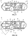
- Figure 10 shows the rotary wheel 204 of the depth dial 202 rotated to a position to provide a maximum depth of penetration of the lancet tip 34 (e.g., setting/indicia 4).
- the eccentric stop surface 216 of the depth dial 202 is correspondingly rotated to where its then-rearward facing portion in the engagement position is farthest forward to stop the forward motion of the extension arm 83a at a maximally advanced position, with the return-spring leg 83 at a maximally deflected angle ⁇ 1. Accordingly, the depth-adjustment mechanism 200 is set to produce the maximally-extended extended position of the lancet carrier 32 and the lancet 30 it carries, i.e., to produce the deepest lancing penetration.
- Figure 11 shows the rotary wheel 204 of the depth dial 202 rotated to a position to provide a minimum depth of penetration (e.g., setting/indicia 1).
- the eccentric stop surface 216 of the depth dial 202 is correspondingly rotated to where its then-rearward facing portion in the engagement position is farthest rearward to stop the forward motion of the extension arm 83a at a minimally advanced position, with the return-spring leg 83 at a minimally deflected angle ⁇ 2 (i.e., angle ⁇ 2 is smaller than angle ⁇ 1).
- the depth-adjustment mechanism 200 is set to produce the minimally-extended extended position of the lancet carrier 32 and the lancet 30 it carries, i.e., to produce the shallowest lancing penetration.
- the now-charged return spring 82 then discharges to retract the lancet carrier to back within the housing 12.
- the lancet carrier 32 is then returned to the neutral position of Figure 7 , with the drive and return springs 80, 82 counter-balancing one another.
- the endcap 20 can be removed, the used lancet 30 removed, and a fresh lancet inserted into the lancet carrier 32 for use. This lancing procedure can then be repeated as desired.
- the extension arm 83a is resiliently deflectable (with respect to the return-spring leg 83) so that its contact with the eccentric stop surface 216 of the depth dial 202 provides for an even "softer" stop with less vibration sensed by the patient being lanced.
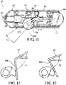
- the angle between the extension arm 83a and the return-spring leg 83 smoothly and progressively decreases from a neutral angle ⁇ 1 (see Figure 12 ) to a deflected angle ⁇ 2 (see Figure 13 ) where the lancet carrier 32 is stopped at the extended position.
- the extension arm 83a may have a different (e.g., stiffer) spring stiffness and/or be connected to the remainder of the return-spring leg 83 by a resiliently deflectable junction.
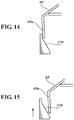
- the adjustably-positioned stop surface is formed by a ramp 216 that is linearly slidable to position different-thickness portions of it for engagement by the extension arm 83a.
- the ramp 216 slides between a maximally extended position (see Figure 14 ) and a minimally extended position (see Figure 15 ).
- the resiliently deflectable extension arm extends from the movable adjustment control member (not the return-spring leg) and engages the return-spring leg to stop forward motion of the lancet.
- the resiliently deflectable extension arm engaged by the lancet carrier is not part of the return spring but instead is provided as a separate spring element.
- the extension arm is a resiliently deflectable extension arm cantilevered from the lancet carrier (or another element that moves with the lancet), but is not an extension of or otherwise a part of the return spring.
- the lancing device is provided with the soft-stop features (the resiliently deflectable extension arm engaging the stop surface) but not the adjustability features (the stop surface being eccentric and rotationally moveable).
- the soft-stop mechanism includes the resiliently deflectable leg operably interposed between the lancet carrier and the stop surface to produce the non-instant stop of the lancet carrier at the extended position to reduce vibration for a less painful lancing experience.
- the stop surface is fixed and not adjustable, so it includes only one portion that is contacted in the engagement position by the resiliently deflectable leg, and it does not include the rotary wheel or any other adjustable control member.
Landscapes
- Health & Medical Sciences (AREA)
- Life Sciences & Earth Sciences (AREA)
- Heart & Thoracic Surgery (AREA)
- Surgery (AREA)
- Biophysics (AREA)
- Pathology (AREA)
- Engineering & Computer Science (AREA)
- Biomedical Technology (AREA)
- Hematology (AREA)
- Medical Informatics (AREA)
- Molecular Biology (AREA)
- Physics & Mathematics (AREA)
- Animal Behavior & Ethology (AREA)
- General Health & Medical Sciences (AREA)
- Public Health (AREA)
- Veterinary Medicine (AREA)
- Dermatology (AREA)
- Pain & Pain Management (AREA)
- Measurement Of The Respiration, Hearing Ability, Form, And Blood Characteristics Of Living Organisms (AREA)
Description
- This application claims the priority benefit of
U.S. Provisional Patent Application Serial No. 61/706,409 filed September 27,2012 - The present invention relates generally to the field of medical devices and procedures, and particularly to lancing devices with depth-adjustment mechanisms for adjusting the penetration depth of lancets.
- Lancing devices are utilized for penetrating the skin of a human or animal subject at a lancing site to obtain a sample of blood or other body fluid for medical testing, as in blood-typing or blood-glucose testing. Known lancing devices commonly include a housing containing a drive mechanism, a charging mechanism for energizing the spring or other biasing means of the drive mechanism, and a release mechanism for releasing the drive mechanism upon actuation. A lancet is typically propelled by the drive mechanism from a retracted position within the housing to an extended position wherein a sharp tip portion of the lancet projects from the housing to prick the subject's skin at a desired lancing site.
- Lancing devices are available in multi-use and disposable designs. In multi-use designs, the lancet is a disposable component that is removably mounted into a receiver or lancet carrier of the drive mechanism. A used lancet is removed from the lancet carrier after sampling for subsequent disposal. An ejection mechanism can optionally be included for discharge of the used lancet from the lancing device. A new, sterile lancet is then replaced into the lancet carrier for further sampling. In disposable designs, the lancet and carrier are an integral part and the lancing device is disposed of after a single use.
- A depth-adjustment mechanism can optionally be provided to adjust the penetration depth of the lancet, to control sample size and/or to minimize pain. Known depth-adjustment mechanisms include endcaps that are adjustably positioned relative to the lancing device housing, but they are generally susceptible to accidental and unknowing manipulation to a different depth setting, and they can be difficult to manipulate for people with limited dexterity. Other known depth-adjustment mechanisms include movable stops that limit the travel of the lancet by contact with the lancet carrier, but they generally increase the vibrations and impact force thereby causing more pain to the patient.
- Accordingly, it can be seen that needs exist for improvements to depth-adjustment mechanisms for lancing devices. It is to the provision of improved lancing devices and lancing depth-adjustment mechanisms that the present invention is primarily directed.
- Generally described, the present invention relates to a lancing device including an improved depth-adjustment mechanism that provides a soft stop for a lancet carrier holding a lancet to reduce vibration and thereby provide a less-painful lancing experience to the patient. The depth-adjustment mechanism includes an adjustably-positioned stop surface, a movable control member operably coupled thereto, and a resiliently deflectable leg that engages the stop surface and the lancet carrier. The lancet carrier engages and deflects the leg in a forward phase of a lancing stroke, and then the deflecting leg engages the stop surface to stop the forward motion of the lancet carrier at an extended lancing position. The control member is adjustably positionable to move different portions of the stop surface into an engagement position where they are contacted by the leg to adjust the extended position and thereby adjust a penetration depth of the lancet to be deeper or shallower. In this way, the resiliently deflectable leg is operably interposed between the lancet carrier and the stop surface to produce a soft (non-instant) stop of the lancet carrier at the extended position to reduce vibration for a less painful lancing experience.
- In an example embodiment, the depth-adjustment mechanism includes a rotary dial having a rotary wheel and a rotary shaft extending axially therefrom, with the wheel forming the movable adjustment member, and with the shaft including an eccentric surface forming the stop surface. The resiliently deflectable leg may be a part of a return spring that retracts the lancer carrier after it reaches the extended position, for example, the leg may include an extension arm that contacts the stop surface and is bent at an angle from the remainder of the return-spring leg.
- In alternative embodiments, the adjustably-positioned stop surface is provided by a ramp that is linearly slidable to place different portions thereof in the engagement position to adjust the penetration depth of the lancet. In other alternative embodiments, the extension arm is resiliently deflectable with respect to the remainder of the leg to provide an even softer stop for the lancet carrier. And in other embodiments, the components of the depth-adjustment mechanism are configured in other arrangements to provide the same soft stop for the lancet carrier, as described herein.
- In another aspect, the invention relates to a depth-adjustment mechanism as described herein for incorporation into a lancing device of the same or a different design as is described herein. And in yet another aspect, the invention relates to a depth-adjustment mechanism including the features described herein for providing the soft stop but without including the features described herein for providing the penetration-depth adjustability.
- These and other aspects, features, and advantages of the invention will be understood with reference to the drawing figures and detailed description herein, and will be realized by means of the various elements and combinations particularly pointed out in the appended claims. It is to be understood that both the foregoing summary and the following brief description of the drawings and detailed description of example embodiments are explanatory of typical embodiments of the invention, and are not unnecessarily restrictive of the invention, as claimed.
-
-
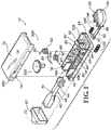
Figure 1 is an exploded perspective view of a lancing device with a depth-adjustment mechanism according to an example embodiment of the present invention. -
Figure 2 is a front perspective view of a lancet carrier of the lancing device ofFigure 1 . -
Figure 3 is a detailed perspective view of the distal end of the lancet carrier ofFigure 2 . -
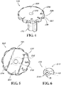
Figure 4 is a top perspective view of a depth dial of the depth-adjustment mechanism of the lancing device ofFigure 1 . -
Figure 5 is a top view of the depth dial ofFigure 4 , showing a hidden eccentric stop surface in phantom lines. -
Figure 6 shows the eccentric stop surface ofFigure 5 . -
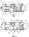
Figure 7 is a top longitudinal cross-sectional view of the lancing device ofFigure 1 in a neutral position. -
Figure 8 shows the lancing device ofFigure 7 in a charged position. -
Figure 9 shows the lancing device ofFigure 7 in a charged and ready position. -
Figure 10 shows the lancing device ofFigure 7 in an actuated position, with the depth-adjustment mechanism configured for maximum depth of penetration. -
Figure 11 shows the lancing device ofFigure 7 in an actuated position, with the depth-adjustment mechanism positioned for minimum depth of penetration. -
Figure 12 is a top view of a portion of a depth-adjustment mechanism of a lancing device according to an alternative embodiment, showing the lancet carrier approaching an extended position. -
Figure 13 shows the portion of a depth-adjustment mechanism ofFigure 12 , with the lancet carrier in the extended position. -
Figure 14 is a top view of a portion of a depth-adjustment mechanism of a lancing device according to another alternative embodiment, adjusted to a maximally extended position. -
Figure 15 shows the portion of a depth-adjustment mechanism ofFigure 14 adjusted to a minimally extended position. - The present invention may be understood more readily by reference to the following detailed description of the invention taken in connection with the accompanying drawing figures, which form a part of this disclosure. It is to be understood that this invention is not limited to the specific devices, methods, conditions, or parameters described and/or shown herein, and that the terminology used herein is for the purpose of describing particular embodiments by way of example only and is not intended to be unnecessarily limiting of the claimed invention.
- Also, as used in the specification including the appended claims, the singular forms "a," "an," and "the" include the plural, and reference to a particular numerical value includes at least that particular value, unless the context clearly dictates otherwise. Ranges may be expressed herein as from "about" one particular value and/or to "about" another particular value. When such a range is expressed, another embodiment includes from the one particular value and/or to the other particular value. Similarly, when values are expressed as approximations, by use of the antecedent "about," it will be understood that the particular value forms another embodiment.
- With reference now to the drawing figures, wherein like reference numbers represent corresponding parts throughout the several views,
Figures 1-11 show alancing device 10 with a depth-adjustment mechanism 200 according to an example embodiment of the present invention. Thelancing device 10 includes a charging mechanism, a drive mechanism, a release mechanism, and ahousing 12 for these components. The drive mechanism includes alancet carrier 32 that carries alancet 30 through a lancing stroke. The charging mechanism is operable to charge the drive mechanism, and the release mechanism is operable to release the lancet carrier to be driven by the charged drive mechanism to propel the lancet carrier (and thus the lancet) through the lancing stroke. - The details of the
housing 12,lancet carrier 32, drive mechanism, charging mechanism, and release mechanism depicted and described herein are representative and not limiting of the invention. Thus, many other conventional housings, lancet carriers, drive mechanisms, charging mechanisms, and/or release mechanisms can be used with good results, as long as they do not interfere with the structures and functionality of the depth-adjustment mechanism, and as long as the drive mechanism (or another mechanism) includes cooperating features as needed to provide the functionality of the depth-adjustment mechanism. That is, the improved depth-adjustment mechanism 200 described and illustrated herein can be incorporated into many other lancing-device designs. - In the depicted embodiment, the
housing 12,lancet carrier 32, drive mechanism, charging mechanism, and release mechanism of thelancing device 10 are substantially similar to those ofU.S. Patent No. 8,034,068 . Thus, repetitive explanation herein will be kept to a minimum while still fully describing the lancingdevice 10. For convenience, many of the reference characters used herein have been selected to match those ofU.S. Patent No. 8,034,068 for common parts. In other embodiments, other designs of lancing devices, with other charge, drive, and/or release mechanisms, can be used with the depth-adjustment mechanism 200 of the present invention. For example, while the depicted lancingdevice 10 is a multi-use device, in other embodiments the depth-adjustment mechanism 200 is incorporated into a disposable lancing device. And while the depicted lancingdevice 10 includes a single mechanism for both charging and releasing the drive mechanism, in other embodiments separate charging and release mechanisms are provided. - Referring primarily to
Figures 1-3 , the depicted lancingdevice 10 includes ahousing 12 defining an axial bore through which the lancet carrier travels along its lancing stroke. The depictedhousing 12 has atop portion 14 connected to abottom portion 16 by one or more inter-engaging surface features. For example, crush pins 14 extending from thetop housing 14 can be received inconduits 16 formed within the bottom housing to permanently or removably couple the housing portions together. In other embodiments, adhesives are used to couple the housing portions together, and/or the housing is formed in other configurations. - The
housing 12 includes a lancingopening 22 at its forward end through which asharp tip 34 of thelancet 30 extends externally in an extended position of the lancing stroke to penetrate the skin of a subject at a lancing site (seeFigures 10-11 ). Thehousing 12 typically includes anendcap 20 removably connected to its forward end so that a usedlancet 30 can be manually removed from the lancingdevice 10 and a fresh lancet can be manually inserted into the device in its place for use. Thus, the lancingopening 22 can be formed in theendcap 20, as depicted. At the rearward end of thehousing 12 opposite theendcap 20 is an opening 24 for receiving a charging/release actuator assembly 26 and for guiding the same along a predefined axial path of travel. - The
lancet carrier 32 of the drive mechanism includes at least one guide element and thehousing 12 includes at least one guide element that engage each other such that the movement of the lancet carrier through the lancing stroke defines a linear stroke axis (see axial centerline inFigure 7 ). In the depicted embodiment, thelancet carrier 32 includes two male guide elements, such as a forward/proximal guide arm 41 and a rear/distal guide arm 43 extending from a lower surface of thelancet carrier 32. And the female guide element includes a guide channel 48 formed in thebottom housing portion 16 and slidingly receiving theguide arms lancet carrier 32 along the lancing stroke axis. Additionally or alternatively, laterally offsetwalls 49a, 49b can be provided on thebottom housing portion 16 to receive thelancet carrier 32 therebetween and linearly guide thelancet carrier 32 as traverses along the lancing stroke axis. In other embodiments, other inter-engaging guide elements are provided to promote linear relative translation (and prevent relative rotation or lateral movement) between these two parts (e.g., channels on the lancet carrier that engage at least one rib within the housing, or other mating guide elements). - The
lancet carrier 32 defines drive and return contact surfaces that are engaged by cooperating features of the drive mechanism to advance and retract it through the lancing stroke. In the depicted embodiment, theguide elements lancet carrier 32 are spaced apart and include respective drive and return contact surfaces 42, 44 that generally face each other, are generally transverse to the lancing stroke axis, and cooperatively define therebetween acontrol opening 45. The drive and return contact surfaces 42, 44 are engaged by other elements of the drive mechanism (which are received in the control opening 45) to control thelancet carrier 32 during the forward and return phases of the lancing stroke, as described below. - In addition, the
lancet carrier 32 includes a lancet mount at its forward end and charging and release features at its rearward end. In the depicted embodiment, the lancet mount is provided by anopening 46 that is sized and shaped to securely but releasably receive and hold thereplaceable lancet 30 during use. The depicted charging features include aU-shaped portion 52 of thelancet carrier 32 that interengages the charging/release actuator assembly 26, with these portions of the lancingdevice 10 being substantially similar to those ofU.S Patent No. 8,034,068 . Further details of the lancet carrier's charge/release features and their interaction with the charging/release mechanism will now be described before completing the description of the drive mechanism. - In the depicted embodiment, the
U-shaped portion 52 of thelancet carrier 32 includes two axially-rearward extendingarms fin 78 that projects generally laterally from one of the arms. The charge/release actuator assembly 26 includes a push/pull button 94, aleg 95 extending axially from the button, and afoot 97 extending laterally from the leg that engages thefin 78 of thelancet carrier 32 when the push/pull button is retracted. As such, retraction of the push/pull button 94 retracts thelancet carrier 32 against a forward-biasing force of the drive mechanism to a charged position where transverse catch surfaces 74, 76 ofchamfered barbs arms U-shaped portion 52 engage cooperating lockingtabs Figure 8 ). - In addition, the push/
pull button 94 includes trigger posts 96, 98 extending axially forward therefrom for engaging chamfer surfaces 66, 68 of the chamferedbarbs lancet carrier 32 in the charged position to be propelled under the influence of the drive mechanism. As such, in the depicted embodiment the push/pull button 94 of theactuator assembly 26 functions as the user interface for both charging and releasing the lancingdevice 10, with the features of the charging mechanism and the release mechanism combined into a single mechanism for both functions. It will be readily understood by persons of ordinary skill in the art how to provide other embodiments with separate charging and release actuators. - The depicted charging mechanism further includes one or more equilibrium springs that induce the push/
pull button 94 into a charged and ready position (seeFigure 9 ). In the depicted embodiment, a push-resistspring 100 and an oppositely opposed pull-resistspring 103 cause the push/pull button 94 to move to an equilibrium position wherein thesprings Figure 9 ). The push-resistspring 100 can be a coil compression spring mounted on aspring post 102 of thehousing 12 and biased between a transverse rearward wall of thehousing 12 and a central portion of a transverse forward wall of the push/pull button 94. For example, the central portion of the push/pull button 94 can be defined between its trigger posts 96, 98 and can include an orifice (not shown) formed therein such that a portion of the pull-resistspring 100 is retained therein. And the pull-resistspring 103 can be a coil compression spring mounted on the charging-button leg 95 and biased between the charging-button foot portion 97 and thelocking tab 64 of thehousing 12. In other embodiments, the lancing device includes other conventional structures operable to manipulate the lancet carrier to charge the drive mechanism, for example, with no or different equilibrium-inducing spring arrangements, with other inter-engaging features of the lancet carrier and charge/release mechanism, and/or with separate charge and release actuators. - Continuing now with the drive mechanism, at least one spring element is provided for driving the
lancet carrier 32 through the forward and return phases of the lancing stroke. In the depicted embodiment, there are two torsion springs, adrive spring 80 and areturn spring 82, that cooperate to drive and return thelancet carrier 32 through the lancing stroke. The drive and return torsion springs 80, 82 include at least one respective leg extending therefrom into the control opening 45 for engagement with the respective drive and return contact surfaces 42, 44 of theguidance elements lancet carrier 32. That is, theleg 81 of thedrive spring 80 engages thedrive contact surface 42 of theproximal drive element 41, and theleg 83 of thereturn spring 82 engages thereturn contact surface 44 of the distal return element 43 (seeFigures 7-11 ). By this engagement, thedrive spring 80 drives thelancet 30 on thelancet carrier 32 from its charged position to its extended position to lance the skin, and thereturn spring 82 retracts the lancet from its extended position back into thehousing 12 after lancing the skin. In the depicted embodiment, thereturn spring 82 also serves to provide depth adjustment to thelancet 30 by cooperating with the depth-adjustment mechanism 200, as described below. - Typically, the drive and return springs 80, 82 are generally similar in shape and form, except with the drive spring being the stronger of the two springs. The
drive torsion spring 80 can be mounted to thehousing 12 on a first axle orpivot 90, and thereturn torsion spring 82 mounted on a second axle orpivot 92, with an inner wall of the housing from which the pivots extend serving as a retainer for the springs. Theaxles - In other embodiments, the return spring is provided by another type of spring element that has a resilient extension leg that engages the drive mechanism (e.g., a leaf or cantilever spring, a compression or tension coil spring that is axially resilient and includes a transverse resilient extension leg, or another resilient member including a resilient extension leg) and also engages the depth-
adjustment mechanism 200 to provide the depth-adjustment functionality described herein. In yet other embodiments, the drive and return functionality is provided by a single spring element (e.g., a coil spring, torsion spring, leaf/cantilever spring, or other resilient member) that includes a resilient extension leg that engages the drive mechanism and also engages the depth-adjustment mechanism 200 to provide the depth-adjustment functionality described herein. And in still other embodiments, a separate drive spring is provided by any other conventional type of spring element (e.g., a compression or tension coil spring, leaf or cantilever spring, or other resilient member), regardless of the type of return spring provided. - Referring primarily to
Figures 4-6 , details of the depth-adjustment mechanism 200 will now be described. The depth-adjustment mechanism 200 provides adjustment to the depth of penetration of thelancet 30 in the skin when the lancet is in the extended position of the lancing stroke. Generally described, the depth-adjustment mechanism 200 includes an adjustably positioned stop surface and a resiliently deflectable leg associated with a movable adjustment control member and a return spring of the drive mechanism (respectively or non-respectively). The lancet carrier 32 (or another element of the drive mechanism) engages and angularly deflects the resiliently deflectable leg in the forward phase of the lancing stroke of the lancet carrier, then the leg (or an extension thereof) engages the stop surface to stop the forward motion of the lancet carrier at the extended position, and then the return spring retracts the lancet carrier back into thehousing 12. - In the depicted embodiment, the depth-
adjustment mechanism 200 includes arotary depth dial 202 having a movable adjustment control member in the form of arotary wheel 204 and arotary shaft 212 extending axially downward therefrom, with the adjustably positioned stop surface in the form of aneccentric stop surface 216 formed on the shaft. To provide for rotational adjustment of thewheel 204 and theeccentric stop surface 216, thedepth dial 202 is rotationally mounted to thehousing 12. In the depicted embodiment, therotary shaft 212 includes anaxially extending opening 210 that rotatably mounts to a pin 99 extending from thehousing 12. In other embodiments, other rotational mounting arrangements can be used, for example these rotational-mounting features can be reversed. - The depicted
depth wheel 204 is generally disc-shaped (or at least a portion of it is) and includes aperipheral portion 206 for manually gripping by the user to rotate the wheel and thereby rotate theeccentric stop surface 216 to the desired depthsetting position. For example, theperipheral portion 206 of thewheel 204 can include a series of alternating surfaces, for example, outwardlyknurled portions 207 and inwardly knurledportions 208 therebetween, to provide enhanced grasping capabilities for users, especially those with reduced or limited dexterity. In addition, indicia such asmarkings 230 can be provided around thedepth wheel 202 corresponding to positions of theeccentric stop surface 216 to indicate the depth of penetration provided by thedepth dial 202. The depth-wheel 204 is positioned so that it is accessible for actuation by a user, for example it can extend partially out of thehousing 12 through anopening 250 for gripping and actuation by the user. Thedepth wheel 204 can be rotated to individually position each of the depth indicia 230 (e.g., numerals 1-4) in a setting position (e.g., extending through theopening 250 and thus visible to the user) to form different depth settings. In other embodiments, the wheel can have no or other conventional gripping features and/or indicia to provide none of or the same functionality. - The adjustably-positionable eccentric stop surface 216 (of the
rotary shaft 212 of the depth dial 202) is positioned within thehousing 12 for inter-operation with thelancet carrier 32. Theeccentric stop surface 216 has a non-uniform radius so that it provides a series of portions with increasingly larger or smaller radiuses. Theeccentric stop surface 216 can be a smooth surface (as depicted), it can have a stepped configuration (e.g., with discrete indexed positions), it can be formed by a series of outwardly (from the shaft) or downwardly (from the wheel) extending tabs or protrusions, and/or it can be provided in other configurations for cooperating with thereturn spring 80 to provide variable lancet-depth adjustment. Typically, theeccentric stop surface 216 does not extend peripherally all the way around theshaft 212, in which case the shaft also includes aperipheral surface portion 214 that is not used as a stop surface, and this surface portion can have a generally uniform radius, as depicted. - In the depicted embodiment, the
eccentric stop surface 216 defines a peripheral profile radiused from a central point of the rotary shaft 212 (see center mark ofFigure 6 ) outward to the periphery of the shaft. For example, a variable radial dimension VD can be defined along the eccentric stop surface 216 (e.g., about 130 degrees of the total 360 degrees periphery), and a uniform radial dimension UD can be defined along the uniform shaft portion 214 (e.g., the remaining about 230 degrees). Thus, therotary shaft 212 has a progressively increased (or decreased) radius and thus thickness that forms theeccentric stop surface 216. - The depth of penetration of the
sharp tip 34 of thelancet 30 is adjusted by adjusting the angular position of thedepth dial 202. Different angular positions of thedepth dial 202 position theeccentric stop surface 216 with different of its portions in the engagement position (facing rearward in the depicted embodiment and in another direction in other embodiments) for engagement by the return-spring extension arm 83a. That is, thedepth dial 202 is rotatably mounted such that its angular position determines which portion of theeccentric stop surface 216 faces rearward and thus will be engaged by theextension arm 83a of thereturn spring 82 as it is deflected by thelancet carrier 32 advancing along the lancing stroke. - The
return contact surface 44 of thelancet carrier 32 contacts theleg 83 of thereturn spring 82 when the lancet carrier is propelled forward from the charged position to the extended position. After contact occurs, the further advancinglancet carrier 32 causes the return-spring leg 83 to angularly deflect, which causes the return-spring extension arm 83a to angularly displace. The return-spring extension arm 83a displaces until it contacts theeccentric stop surface 216, which stops its movement, which in turn stops the movement of the return-spring leg 83, which in turn stops the movement of thelancet carrier 32, thereby defining its extended position. In this way, theeccentric stop surface 216 is rammed into not by a rigid member of the lancet carrier, but instead by the resilientlydeflectable return spring 82. - The
indicia 230 of thedepth wheel 204 correspond respectively to different portions of theeccentric stop surface 216 so that positioning each of the indicia in a setting position places the corresponding stop-surface portion in the engagement position to stop the forward motion of thelancet carrier 32 along the lancing stroke. For example, inFigure 10 the angular position of the eccentric stop surface 216 (as determined by the angular position of the depth wheel 204) provides a maximum depth of lancet penetration, because the rearward-facing portion of the stop surface is farthest forward so that return-spring extension arm 83a contacts it after the lancet carrier has traveled farthest. But inFigure 11 , the angular position of theeccentric stop surface 216 provides a minimum depth of lancet penetration, because the rearward-facing portion of the stop surface is farthest rearward so that return-spring extension arm 83a contacts it after the lancet carrier has traveled least far. Angularly positioning thedepth wheel 204 between the maximum-depth setting and the minimum-depth setting provides for one or a plurality of intermediate-depth settings. Optionally, the housing can include an indexing feature that engages cooperating indexing features of the depth wheel 204 (e.g., detents) to discretely define the depth settings. - In the depicted embodiment, the
extension arm 83a extends longitudinally from the return-spring leg 83 and is integrally formed as a part thereof. As such, reference to the return-spring leg 83 includes theextension arm 83a, and vice versa. In some depth settings, thereturn contact surface 44 of thelancet carrier 32 may contact theextension arm 83a of the return-spring leg 83, and not just the remainder of the return-spring leg. Typically, both segments of thereturn spring 82 are made of the same resiliently deflectable material (e.g., metal or plastic), with the extension arm bent at an angle from the remainder of the return-spring leg 83. When theextension arm 83a hits thestop surface 216, generally it does not deflect (e.g., it may deflect but only insubstantially), so that position defines the extended position of thelancet carrier 32. - Having described in detail the structure of the lancing
device 10 and its depth-adjustment mechanism 200, their sequential operation will now be described with particular reference toFigures 7-11 . In a neutral position (Figure 7 ), theleg 81 of thedrive spring 80 and theleg 83 of thereturn spring 82 are engaged with their respective drive and return contact surfaces 42, 44 of thelancet carrier 32. Thus, the drive and return springs 80, 82 counter-balance one another such that thelancet carrier 32 generally remains in its neutral position. The pull-resist and push-resist equilibrium springs 100, 103 are typically in their neutral positions, or if charged in any respect they do not overpower the drive and return springs 80, 82 to significantly alter the position of thelancet carrier 32. - In a charged position (see
Figure 8 ), rearward/distal retraction (as indicated by the directional arrow) by a user of the push/pull button 94 has caused retraction of itsfoot portion 97 to retract the engaged therebyfin 78 of thelancet carrier 32. This retraction of thelancet carrier 32 has in turn caused retraction of the lancet-carrierdrive contact surface 42 against the drive-spring leg 81 to charge thedrive spring 80. At the same time, thereturn contact surface 44 of thelancet carrier 32 has been retracted away from engagement with thereturn spring 82. In the charged position, thebarbs U-shaped portion 52 of the retractedlancet carrier 32 have releasably engaged the cooperating lockingtabs housing 12 to retain the lancet carrier in the charged position. In addition, the pull-resistspring 103 has been charged by retraction of the push/pull button 94 to the charging position. - In a charged and ready position (see
Figure 9 ), the push/pull button 94 has been released by the user. Upon releasing the push/pull button 94, the charged pull-resist and push-resist equilibrium springs 100,103 cause the push/pull button 94 to move proximally inward/forward to an equilibrium position (relative to the fully-retracted charged position ofFigure 8 ). As the push/pull button 94 translates proximally forward to its equilibrium position, the opening 24 in thehousing 12 and the U-shaped portion 65 of the locking tab 64 (seeFigure 1 ) help guide the movement of the push/pull button and theleg 95 extending therefrom during discharging of the pull-resist and push-resistsprings - To actuate the lancing
device 10, the push/pull button 94 is now pressed by the user (as indicated by the directional arrow ofFigure 10 ). As the push/pull button 94 translates forward, its trigger posts 96, 98 come into engagement with the chamferedbarbs arms lancet carrier 32 and deflect them inwardly. This releases thebarbs tabs housing 12 to release thelancet carrier 32 to be propelled through the lancing stroke under the influence of the chargeddrive spring 80. The engagement of theleg 81 of the chargeddrive spring 80 with thedrive contact surface 41 of thelancet carrier 32 then propels the lancet carrier forward toward its extended position. As thelancet carrier 32 advances forward, itsreturn contact surface 44 comes into contact with theleg 83 of thereturn spring 82 to begin charging the return spring. Because thedrive spring 82 is stiffer than thereturn spring 80, thelancet carrier 32 continues moving forward under the influence of the discharging drive spring and against the influence of the charging return spring until it reaches its extended position. - The depth-
adjustment mechanism 200 is adjustable between a series of depth settings to adjustably set the extended position of thelancet carrier 32. The momentum oflancet carrier 32 propelled forward by thedrive spring 80 causes theleg 83 of thereturn spring 82 to angularly deflect (e.g., in a clockwise direction in the depicted views) from its neutral angular position (seeFigure 9 ) to charge the return spring. As thelancet carrier 32 continues translating forward, theextension arm 83a extending from the return-spring leg 83 transversely across the lancing stroke axis swings forward into contact with theeccentric stop surface 216 of therotary depth dial 202. This engagement between theextension arm 83a of thereturn spring 82 and theeccentric stop surface 216 of therotary depth dial 202 stops any further angular deflection of the return-spring leg 83. In turn, the engagement between the stopped return-spring leg 83 and the lancet-carrierreturn contact surface 44 stops any further forward movement of thelancet carrier 32. So this defines the extended position of thelancet carrier 32, which correlates to the extended-position deflection angle α1 (relative to its neutral position ofFigure 9 ) of the return-spring leg 83. - In this way, the
lancet carrier 32 is not stopped at its extended position by contacting a fixed mechanical stop and thereby producing a "hard" stop. Instead, thelancet carrier 32 is stopped by contacting a resilientlydeflectable spring leg 83 that is being deflected through an angular motion, with the spring-leg angular motion slowing down as the lancet carrier advances and stopped upon the spring leg contacting a fixedmechanical stop 216, and with the stopped spring-leg deflection thus stopping the forward motion of the lancet carrier. The resilientlydeflectable spring leg 83 being operably interposed between thelancet carrier 32 and themechanical stop 216 produces a "soft" (non-instant) stop. With this soft stop, there is less vibration produced and transmitted through the lancet to the patient, resulting in a less painful lancing experience for the patient. - The deflection angle of the return-
spring leg 83 when theextension arm 83a has contacted and been stopped by theeccentric stop surface 216 of therotary depth dial 202 determines the forward-most position of thelancet carrier 32 and thus determines the depth of penetration. For example,Figure 10 shows therotary wheel 204 of thedepth dial 202 rotated to a position to provide a maximum depth of penetration of the lancet tip 34 (e.g., setting/indicia 4). In this position, theeccentric stop surface 216 of thedepth dial 202 is correspondingly rotated to where its then-rearward facing portion in the engagement position is farthest forward to stop the forward motion of theextension arm 83a at a maximally advanced position, with the return-spring leg 83 at a maximally deflected angle α1. Accordingly, the depth-adjustment mechanism 200 is set to produce the maximally-extended extended position of thelancet carrier 32 and thelancet 30 it carries, i.e., to produce the deepest lancing penetration. - To highlight the adjustability feature,
Figure 11 shows therotary wheel 204 of thedepth dial 202 rotated to a position to provide a minimum depth of penetration (e.g., setting/indicia 1). In this position, theeccentric stop surface 216 of thedepth dial 202 is correspondingly rotated to where its then-rearward facing portion in the engagement position is farthest rearward to stop the forward motion of theextension arm 83a at a minimally advanced position, with the return-spring leg 83 at a minimally deflected angle α2 (i.e., angle α2 is smaller than angle α1). Accordingly, the depth-adjustment mechanism 200 is set to produce the minimally-extended extended position of thelancet carrier 32 and thelancet 30 it carries, i.e., to produce the shallowest lancing penetration. - Upon the
lancet carrier 32 reaching its extended position to puncture the skin (seeFigure 10 ), the now-chargedreturn spring 82 then discharges to retract the lancet carrier to back within thehousing 12. Thelancet carrier 32 is then returned to the neutral position ofFigure 7 , with the drive and return springs 80, 82 counter-balancing one another. Theendcap 20 can be removed, the usedlancet 30 removed, and a fresh lancet inserted into thelancet carrier 32 for use. This lancing procedure can then be repeated as desired. - In an alternative embodiment shown in
Figures 12-13 , theextension arm 83a is resiliently deflectable (with respect to the return-spring leg 83) so that its contact with theeccentric stop surface 216 of thedepth dial 202 provides for an even "softer" stop with less vibration sensed by the patient being lanced. This is because the angle between theextension arm 83a and the return-spring leg 83 smoothly and progressively decreases from a neutral angle β1 (seeFigure 12 ) to a deflected angle β2 (seeFigure 13 ) where thelancet carrier 32 is stopped at the extended position. In such embodiments, theextension arm 83a may have a different (e.g., stiffer) spring stiffness and/or be connected to the remainder of the return-spring leg 83 by a resiliently deflectable junction. - In another alternative embodiment shown in
Figures 14-15 , the adjustably-positioned stop surface is formed by aramp 216 that is linearly slidable to position different-thickness portions of it for engagement by theextension arm 83a. Theramp 216 slides between a maximally extended position (seeFigure 14 ) and a minimally extended position (seeFigure 15 ). - In other embodiments, the resiliently deflectable extension arm extends from the movable adjustment control member (not the return-spring leg) and engages the return-spring leg to stop forward motion of the lancet. In yet other embodiments, the resiliently deflectable extension arm engaged by the lancet carrier is not part of the return spring but instead is provided as a separate spring element. In still other embodiments, the extension arm is a resiliently deflectable extension arm cantilevered from the lancet carrier (or another element that moves with the lancet), but is not an extension of or otherwise a part of the return spring.
- And in some embodiments, the lancing device is provided with the soft-stop features (the resiliently deflectable extension arm engaging the stop surface) but not the adjustability features (the stop surface being eccentric and rotationally moveable). In such embodiments, the soft-stop mechanism includes the resiliently deflectable leg operably interposed between the lancet carrier and the stop surface to produce the non-instant stop of the lancet carrier at the extended position to reduce vibration for a less painful lancing experience. But the stop surface is fixed and not adjustable, so it includes only one portion that is contacted in the engagement position by the resiliently deflectable leg, and it does not include the rotary wheel or any other adjustable control member.
- While the invention has been described with reference to example embodiments, it will be understood by those skilled in the art that a variety of modifications, additions, and deletions are inherently and implicitly within the scope of the invention, as defined by the following claims.
Claims (20)
- A lancing device (10) for propelling a lancet (30) through a lancing stroke, the lancing device comprising:a housing (12) including an axial bore;a drive mechanism including a lancet carrier (32) and a drive spring (80), the lancet carrier (32) holding the lancet (30) and translatable axially within the housing bore through the lancing stroke, and the drive spring (80) adapted to propel the lancet carrier (32) through a forward phase of the lancing stroke;characterised by a depth-adjustment mechanism (200) including an adjustably positioned stop surface (216), a movable adjustment control member (202) operably coupled thereto, and a resiliently deflectable leg (83) operably interposed between the lancet carrier (32) and the stop surface (216), wherein the lancet carrier (32) engages and deflects the leg (83) in the forward phase of the lancing stroke, and the deflecting leg (83) then engages the stop surface (216) to stop the leg deflection and thus stop the forward motion of the lancet carrier (32) at an extended position for lancing, and wherein the control member (202) is adjustably positionable to move different portions of the stop surface (216) into an engagement position where they are contacted by the leg (83) to adjust the extended position and thereby adjust a penetration depth of the lancet (30).
- The lancing device of Claim 1, wherein the resiliently deflectable leg (83) being operably interposed between the lancet carrier (32) and the stop surface (216) produces a non- instant stop of the lancet carrier (32) at the extended position to reduce vibration for a less painful lancing experience.
- The lancing device of Claim 1, wherein the lancet carrier defines a return contact surface (44) that engages the resiliently deflectable leg (83).
- The lancing device of Claim 1, wherein the drive mechanism includes a return spring (82) adapted to contact and be charged by the lancet carrier (32) during the forward phase of the lancing stroke and then discharge and retract the lancet carrier (32) from the extended position, wherein the return spring (82) includes the resiliently deflectable leg (83).
- The lancing device of Claim 4, wherein the return spring (82) is a torsion spring.
- The lancing device of Claim 4, wherein the return-spring leg (83) includes an extension arm (83a) that contacts the stop surface (216) in the lancet-carrier extended position.
- The lancing device of Claim 6, wherein the extension arm (83a) is angled with respect to the return-spring leg (83) and extends transversely across an axis defined by the lancing stroke.
- The lancing device of Claim 7, wherein the extension arm (83a) angularly deflects relative to the remainder of the leg (83) upon contact with the stop surface (216).
- The lancing device of Claim 1, wherein the adjustably positioned stop surface (216) is defined by an eccentric stop surface of a rotary shaft (212) rotationally mounted to the housing (12).
- The lancing device of Claim 9, wherein the rotary shaft (212) is rotationally adjustable to place the different portions of the eccentric stop surface (216) in the engagement position where they are contacted by the leg (83) to adjust the extended position and thereby adjust the penetration depth of the lancet (30).
- The lancing device of Claim 9, wherein the different portions of the eccentric stop surface (216) have different radial dimensions.
- The lancing device of Claim 9, wherein the movable control member (202) is a rotary wheel (204) from which the rotary shaft (212) axially extends, with the rotary wheel (204) accessible by a user to permit rotational movement thereof to adjust the portion of the eccentric stop surface (216) in the engagement position and thereby adjust the penetration depth of the lancet (30).
- The lancing device of Claim 10, wherein the rotary wheel (204) includes indicia (230) corresponding to the different portions of the eccentric stop surface (216).
- The lancing device of Claim 1, wherein the adjustably positioned stop surface (216) is defined by a ramp that is linearly slidable to place the different portions thereof in the engagement position where they are contacted by the leg (83) to adjust the extended position and thereby adjust the penetration depth of the lancet (30).
- A depth-adjustment mechanism for a lancing device, the lancing device comprising a lancet carrier (32) holding a lancet (30) and translatable axially through a lancing stroke, a drive spring (80) adapted to propel the lancet carrier (32) through a forward phase of the lancing stroke to an extended position for lancing, and a return spring (82) adapted to retract the lancet carrier (32) from the extended position, the depth-adjustment mechanism characterised by:an adjustably positioned stop surface (216),a movable adjustment control member (202) operably coupled to the stop surface (216); anda resiliently deflectable leg (83) formed by the return spring (82) and including an extension arm (83a), the extension arm extending transversely across an axis defined by the lancing stroke, contacting the stop surface (216) in the lancet-carrier extended position, and operably interposed between the lancet carrier (32) and the stop surface (216),wherein the lancet carrier (32) engages and deflects the extension arm (83a) in the forward phase of the lancing stroke, and the deflecting extension arm (83a) then engages the stop surface (216) to stop the extension-arm deflection and thus stop the forward motion of the lancet carrier (32) at the extended position, wherein the extension arm (83a) being operably interposed between the lancet carrier (32) and the stop surface (216) produces a non-instant stop of the lancet carrier (32) at the extended position to reduce vibration for a less painful lancing experience, and wherein the control member (202) is adjustably positionable to move different portions of the stop surface (216) into an engagement position where they are contacted by the extension arm (83a) to adjust the extended position and thereby adjust a penetration depth of the lancet (30).
- The depth-adjustment mechanism of Clam 15, wherein the adjustably positioned stop surface (216) is defined by an eccentric stop surface of a rotary shaft (212) rotationally mounted to the housing (12).
- The depth-adjustment mechanism of Claim 16, wherein the rotary shaft (212) is rotationally adjustable to place the different portions of the eccentric stop surface (216) in the engagement position where they are contacted by the leg (83) to adjust the extended position and thereby adjust the penetration depth of the lancet (30), wherein the different portions of the eccentric stop surface (216) have different radial dimensions.
- The depth-adjustment mechanism of Claim 15, wherein the adjustably positioned stop surface (216) is defined by a ramp that is linearly slidable to place the different portions thereof in the engagement position where they are contacted by the leg (83) to adjust the extended position and thereby adjust the penetration depth of the lancet (30).
- A lancing device for propelling a lancet (30) through a lancing stroke, the lancing device comprising:a housing (12) including an axial bore;a drive mechanism including a lancet carrier (32) and a drive spring (80), the lancet carrier (32) holding the lancet (30) and translatable axially within the housing bore through the lancing stroke, and the drive spring (80) adapted to propel the lancet carrier (32) through a forward phase of the lancing stroke;characterised by a soft-stop mechanism including a stop surface (216) and a resiliently deflectable leg (83) operably interposed between the lancet carrier (32) and the stop surface (216), wherein the lancet carrier (32) engages and deflects the leg (83) in the forward phase of the lancing stroke, and the deflecting leg (83) then engages the stop surface (216) to stop the leg deflection (83) and thus stop the forward motion of the lancet carrier (32) at an extended position for lancing, wherein the resiliently deflectable leg (83) being operably interposed between the lancet carrier (32) and the stop surface (216) produces a non-instant stop of the lancet carrier (32) at the extended position to reduce vibration for a less painful lancing experience.
- The lancing device of Claim 19, wherein the lancing device further includes a return spring (82) adapted to contact and be charged by the lancet carrier (32) during the forward phase of the lancing stroke and then discharge and retract the lancet carrier (32) from the extended position, the return spring (82) includes the resiliently deflectable leg (83), and the return-spring leg (83) includes an extension arm (83a) that extends transversely across an axis defined by the lancing stroke and that contacts the stop surface (216) in the lancet-carrier extended position.
Applications Claiming Priority (2)
| Application Number | Priority Date | Filing Date | Title |
|---|---|---|---|
| US201261706409P | 2012-09-27 | 2012-09-27 | |
| PCT/US2013/061543 WO2014052362A1 (en) | 2012-09-27 | 2013-09-25 | Depth-adjust mechanism for lancing device |
Publications (2)
| Publication Number | Publication Date |
|---|---|
| EP2900141A1 EP2900141A1 (en) | 2015-08-05 |
| EP2900141B1 true EP2900141B1 (en) | 2018-08-22 |
Family
ID=49328639
Family Applications (1)
| Application Number | Title | Priority Date | Filing Date |
|---|---|---|---|
| EP13774872.9A Active EP2900141B1 (en) | 2012-09-27 | 2013-09-25 | Depth-adjust mechanism for lancing device |
Country Status (5)
| Country | Link |
|---|---|
| US (1) | US10292634B2 (en) |
| EP (1) | EP2900141B1 (en) |
| JP (1) | JP6313769B2 (en) |
| CA (1) | CA2884845C (en) |
| WO (1) | WO2014052362A1 (en) |
Families Citing this family (2)
| Publication number | Priority date | Publication date | Assignee | Title |
|---|---|---|---|---|
| SE542496C2 (en) * | 2018-09-20 | 2020-05-26 | Ind Stockholm Ab | Improved activation and retraction mechanism for lancing devices |
| CN112972834B (en) * | 2021-02-04 | 2022-07-08 | 南通大学附属医院 | Positioning auxiliary device for peripheral arteriovenous puncture catheterization |
Family Cites Families (43)
| Publication number | Priority date | Publication date | Assignee | Title |
|---|---|---|---|---|
| DE2642896C3 (en) * | 1976-09-24 | 1980-08-21 | 7800 Freiburg | Precision snapper for setting standard stab wounds in the skin for diagnostic purposes |
| EP0166574A3 (en) * | 1984-06-28 | 1987-06-16 | Mitchell P. Dombrowski, M.D. | Fetal blood sampling instrument |
| US4735203A (en) * | 1986-12-12 | 1988-04-05 | Ryder International Corporation | Retractable lancet |
| US4924879A (en) * | 1988-10-07 | 1990-05-15 | Brien Walter J O | Blood lancet device |
| DE4212315A1 (en) * | 1992-04-13 | 1993-10-14 | Boehringer Mannheim Gmbh | Blood lancet device for drawing blood for diagnostic purposes |
| US5318583A (en) * | 1992-05-05 | 1994-06-07 | Ryder International Corporation | Lancet actuator mechanism |
| US5527334A (en) * | 1994-05-25 | 1996-06-18 | Ryder International Corporation | Disposable, retractable lancet |
| WO1997004707A1 (en) * | 1995-07-28 | 1997-02-13 | Apls Co., Ltd. | Assembly for adjusting piercing depth of lancet |
| US6015392A (en) * | 1996-05-17 | 2000-01-18 | Mercury Diagnostics, Inc. | Apparatus for sampling body fluid |
| US5772677A (en) * | 1996-09-24 | 1998-06-30 | International Technidyne Corporation | Incision device capable of automatic assembly and a method of assembly |
| US5984940A (en) * | 1997-05-29 | 1999-11-16 | Atrion Medical Products, Inc. | Lancet device |
| US5797940A (en) * | 1997-05-30 | 1998-08-25 | International Technidyne Corporation | Adjustable skin incision device |
| US6045567A (en) * | 1999-02-23 | 2000-04-04 | Lifescan Inc. | Lancing device causing reduced pain |
| US6283982B1 (en) | 1999-10-19 | 2001-09-04 | Facet Technologies, Inc. | Lancing device and method of sample collection |
| CA2287757A1 (en) | 1999-10-29 | 2001-04-29 | Medical Plastic Devices M.P.D. Inc. | Disposable lancet |
| US6358265B1 (en) * | 2000-07-18 | 2002-03-19 | Specialized Health Products, Inc. | Single-step disposable safety lancet apparatus and methods |
| US8801740B2 (en) * | 2001-07-11 | 2014-08-12 | Arkray, Inc. | Adjustable lancing device |
| JP4320255B2 (en) * | 2001-09-26 | 2009-08-26 | エフ ホフマン−ラ ロッシュ アクチェン ゲゼルシャフト | Portable instrument for collecting body fluids |
| US20040098010A1 (en) * | 2001-10-22 | 2004-05-20 | Glenn Davison | Confuser crown skin pricker |
| US7297152B2 (en) * | 2001-10-31 | 2007-11-20 | Arkray, Inc. | Lancing apparatus |
| DE10208575C1 (en) * | 2002-02-21 | 2003-08-14 | Hartmann Paul Ag | Blood analyzer device comprises needles, test media, analyzer and display, and has carrier turned with respect to main body, to position needle and test media |
| US8267870B2 (en) * | 2002-04-19 | 2012-09-18 | Sanofi-Aventis Deutschland Gmbh | Method and apparatus for body fluid sampling with hybrid actuation |
| US7510564B2 (en) * | 2003-06-27 | 2009-03-31 | Abbott Diabetes Care Inc. | Lancing device |
| JP2007502666A (en) * | 2003-08-20 | 2007-02-15 | ファセット・テクノロジーズ・エルエルシー | Multi-lancet device with aseptic cap repositioning mechanism |
| US20080082117A1 (en) | 2003-11-12 | 2008-04-03 | Facet Technologies, Llc | Lancing device |
| WO2009067269A1 (en) * | 2007-01-12 | 2009-05-28 | Facet Technologies, Llc | Multi-lancet cartridge and lancing device |
| JP4772777B2 (en) * | 2004-03-02 | 2011-09-14 | ファセット・テクノロジーズ・エルエルシー | Compact multipurpose lansing device |
| US8257380B2 (en) * | 2004-06-29 | 2012-09-04 | Stat Medical Devices, Inc. | Adjustabable disposable/single-use lancet device and method |
| JP2008504893A (en) * | 2004-06-30 | 2008-02-21 | ファセット・テクノロジーズ・エルエルシー | Puncture device and multi-lancet cartridge |
| WO2006031535A2 (en) | 2004-09-09 | 2006-03-23 | Bayer Healthcare Llc | Single puncture lancing fixture with depth adjustment and control of contact force |
| US20060129122A1 (en) * | 2004-12-06 | 2006-06-15 | Wyrick Ronald E | Method and apparatus for delivering epinephrine |
| US7909842B2 (en) * | 2006-06-15 | 2011-03-22 | Abbott Diabetes Care Inc. | Lancing devices having depth adjustment assembly |
| EP1990001A1 (en) * | 2007-05-10 | 2008-11-12 | Roche Diagnostics GmbH | Piercing system and fleam conveyor |
| WO2008157610A1 (en) * | 2007-06-19 | 2008-12-24 | Stat Medical Devices, Inc. | Lancet device with depth adjustment and lancet removal system and method |
| WO2009075907A2 (en) * | 2007-07-05 | 2009-06-18 | Facet Technologies, Llc | Multi-lancet cartridge and lancing device |
| EP2039293A1 (en) * | 2007-09-19 | 2009-03-25 | F. Hoffman-la Roche AG | Combination drive for a sample extraction system for obtaining a liquid sample |
| CN100546542C (en) * | 2008-07-09 | 2009-10-07 | 苏州施莱医疗器械有限公司 | Disposal safety simple pendulum arm cut type blood taking needle |
| US8449480B2 (en) | 2008-08-07 | 2013-05-28 | Nova Biomedical Corporation | Single use lancet sensor assembly and meter |
| US9095293B2 (en) * | 2008-12-18 | 2015-08-04 | Facet Technologies, Llc | Lancing device and lancet |
| US9517027B2 (en) * | 2009-07-10 | 2016-12-13 | Facet Techonologies, Llc | Advancement mechanism for cartridge-based devices |
| GB0919568D0 (en) * | 2009-11-09 | 2009-12-23 | Owen Mumford Ltd | Skin stimulus |
| SG194252A1 (en) * | 2012-04-20 | 2013-11-29 | Medipurpose Pte Ltd | A lancet |
| DE202012102771U1 (en) * | 2012-07-24 | 2012-08-09 | Dieter Schmiedl | Lancing device for handling lancing sample carriers based on a microliter pipette tip |
-
2013
- 2013-09-25 JP JP2015534611A patent/JP6313769B2/en active Active
- 2013-09-25 CA CA2884845A patent/CA2884845C/en active Active
- 2013-09-25 WO PCT/US2013/061543 patent/WO2014052362A1/en active Application Filing
- 2013-09-25 EP EP13774872.9A patent/EP2900141B1/en active Active
- 2013-09-25 US US14/036,154 patent/US10292634B2/en active Active
Non-Patent Citations (1)
| Title |
|---|
| None * |
Also Published As
| Publication number | Publication date |
|---|---|
| CA2884845C (en) | 2020-12-29 |
| EP2900141A1 (en) | 2015-08-05 |
| JP6313769B2 (en) | 2018-04-18 |
| US10292634B2 (en) | 2019-05-21 |
| CA2884845A1 (en) | 2014-04-03 |
| JP2015533556A (en) | 2015-11-26 |
| WO2014052362A1 (en) | 2014-04-03 |
| US20140088633A1 (en) | 2014-03-27 |
Similar Documents
| Publication | Publication Date | Title |
|---|---|---|
| US9095293B2 (en) | Lancing device and lancet | |
| US10105086B2 (en) | Twist-to-charge mechanism of lancing device | |
| JP2702374B2 (en) | Blood lancet device for blood collection | |
| US8858582B2 (en) | Push activation lancet device | |
| US20100145377A1 (en) | Lancing Device For Minimizing Pain | |
| EP2661224B1 (en) | Contact activated incision device | |
| SG177566A1 (en) | Lancet device with lance retraction | |
| EP2555680B1 (en) | Lancing device with tethered depth-control mechanism | |
| EP2653100B1 (en) | Lancet device capable of adjusting subcutaneous peneration depth | |
| EP2900141B1 (en) | Depth-adjust mechanism for lancing device | |
| EP2861143B1 (en) | Uni-directional drive mechanism for lancing device | |
| EP2861144B1 (en) | Lancing device endcap with internal dial-driven depth adjust | |
| EP2836125B1 (en) | Lancing device with side activated charge and eject mechanisms | |
| EP2836124B1 (en) | Lancing device with moving pivot depth adjust |
Legal Events
| Date | Code | Title | Description |
|---|---|---|---|
| PUAI | Public reference made under article 153(3) epc to a published international application that has entered the european phase |
Free format text: ORIGINAL CODE: 0009012 |
|
| 17P | Request for examination filed |
Effective date: 20150311 |
|
| AK | Designated contracting states |
Kind code of ref document: A1 Designated state(s): AL AT BE BG CH CY CZ DE DK EE ES FI FR GB GR HR HU IE IS IT LI LT LU LV MC MK MT NL NO PL PT RO RS SE SI SK SM TR |
|
| AX | Request for extension of the european patent |
Extension state: BA ME |
|
| DAX | Request for extension of the european patent (deleted) | ||
| 17Q | First examination report despatched |
Effective date: 20170721 |
|
| GRAP | Despatch of communication of intention to grant a patent |
Free format text: ORIGINAL CODE: EPIDOSNIGR1 |
|
| INTG | Intention to grant announced |
Effective date: 20180309 |
|
| GRAS | Grant fee paid |
Free format text: ORIGINAL CODE: EPIDOSNIGR3 |
|
| GRAA | (expected) grant |
Free format text: ORIGINAL CODE: 0009210 |
|
| AK | Designated contracting states |
Kind code of ref document: B1 Designated state(s): AL AT BE BG CH CY CZ DE DK EE ES FI FR GB GR HR HU IE IS IT LI LT LU LV MC MK MT NL NO PL PT RO RS SE SI SK SM TR |
|
| REG | Reference to a national code |
Ref country code: GB Ref legal event code: FG4D |
|
| REG | Reference to a national code |
Ref country code: CH Ref legal event code: EP |
|
| REG | Reference to a national code |
Ref country code: AT Ref legal event code: REF Ref document number: 1031516 Country of ref document: AT Kind code of ref document: T Effective date: 20180915 |
|
| REG | Reference to a national code |
Ref country code: IE Ref legal event code: FG4D |
|
| REG | Reference to a national code |
Ref country code: DE Ref legal event code: R096 Ref document number: 602013042440 Country of ref document: DE |
|
| REG | Reference to a national code |
Ref country code: FR Ref legal event code: PLFP Year of fee payment: 6 |
|
| REG | Reference to a national code |
Ref country code: NL Ref legal event code: MP Effective date: 20180822 |
|
| REG | Reference to a national code |
Ref country code: LT Ref legal event code: MG4D |
|
| PG25 | Lapsed in a contracting state [announced via postgrant information from national office to epo] |
Ref country code: NL Free format text: LAPSE BECAUSE OF FAILURE TO SUBMIT A TRANSLATION OF THE DESCRIPTION OR TO PAY THE FEE WITHIN THE PRESCRIBED TIME-LIMIT Effective date: 20180822 Ref country code: IS Free format text: LAPSE BECAUSE OF FAILURE TO SUBMIT A TRANSLATION OF THE DESCRIPTION OR TO PAY THE FEE WITHIN THE PRESCRIBED TIME-LIMIT Effective date: 20181222 Ref country code: RS Free format text: LAPSE BECAUSE OF FAILURE TO SUBMIT A TRANSLATION OF THE DESCRIPTION OR TO PAY THE FEE WITHIN THE PRESCRIBED TIME-LIMIT Effective date: 20180822 Ref country code: LT Free format text: LAPSE BECAUSE OF FAILURE TO SUBMIT A TRANSLATION OF THE DESCRIPTION OR TO PAY THE FEE WITHIN THE PRESCRIBED TIME-LIMIT Effective date: 20180822 Ref country code: GR Free format text: LAPSE BECAUSE OF FAILURE TO SUBMIT A TRANSLATION OF THE DESCRIPTION OR TO PAY THE FEE WITHIN THE PRESCRIBED TIME-LIMIT Effective date: 20181123 Ref country code: NO Free format text: LAPSE BECAUSE OF FAILURE TO SUBMIT A TRANSLATION OF THE DESCRIPTION OR TO PAY THE FEE WITHIN THE PRESCRIBED TIME-LIMIT Effective date: 20181122 Ref country code: FI Free format text: LAPSE BECAUSE OF FAILURE TO SUBMIT A TRANSLATION OF THE DESCRIPTION OR TO PAY THE FEE WITHIN THE PRESCRIBED TIME-LIMIT Effective date: 20180822 Ref country code: SE Free format text: LAPSE BECAUSE OF FAILURE TO SUBMIT A TRANSLATION OF THE DESCRIPTION OR TO PAY THE FEE WITHIN THE PRESCRIBED TIME-LIMIT Effective date: 20180822 Ref country code: BG Free format text: LAPSE BECAUSE OF FAILURE TO SUBMIT A TRANSLATION OF THE DESCRIPTION OR TO PAY THE FEE WITHIN THE PRESCRIBED TIME-LIMIT Effective date: 20181122 |
|
| REG | Reference to a national code |
Ref country code: AT Ref legal event code: MK05 Ref document number: 1031516 Country of ref document: AT Kind code of ref document: T Effective date: 20180822 |
|
| PG25 | Lapsed in a contracting state [announced via postgrant information from national office to epo] |
Ref country code: LV Free format text: LAPSE BECAUSE OF FAILURE TO SUBMIT A TRANSLATION OF THE DESCRIPTION OR TO PAY THE FEE WITHIN THE PRESCRIBED TIME-LIMIT Effective date: 20180822 Ref country code: AL Free format text: LAPSE BECAUSE OF FAILURE TO SUBMIT A TRANSLATION OF THE DESCRIPTION OR TO PAY THE FEE WITHIN THE PRESCRIBED TIME-LIMIT Effective date: 20180822 Ref country code: HR Free format text: LAPSE BECAUSE OF FAILURE TO SUBMIT A TRANSLATION OF THE DESCRIPTION OR TO PAY THE FEE WITHIN THE PRESCRIBED TIME-LIMIT Effective date: 20180822 |
|
| PG25 | Lapsed in a contracting state [announced via postgrant information from national office to epo] |
Ref country code: RO Free format text: LAPSE BECAUSE OF FAILURE TO SUBMIT A TRANSLATION OF THE DESCRIPTION OR TO PAY THE FEE WITHIN THE PRESCRIBED TIME-LIMIT Effective date: 20180822 Ref country code: IT Free format text: LAPSE BECAUSE OF FAILURE TO SUBMIT A TRANSLATION OF THE DESCRIPTION OR TO PAY THE FEE WITHIN THE PRESCRIBED TIME-LIMIT Effective date: 20180822 Ref country code: CZ Free format text: LAPSE BECAUSE OF FAILURE TO SUBMIT A TRANSLATION OF THE DESCRIPTION OR TO PAY THE FEE WITHIN THE PRESCRIBED TIME-LIMIT Effective date: 20180822 Ref country code: ES Free format text: LAPSE BECAUSE OF FAILURE TO SUBMIT A TRANSLATION OF THE DESCRIPTION OR TO PAY THE FEE WITHIN THE PRESCRIBED TIME-LIMIT Effective date: 20180822 Ref country code: PL Free format text: LAPSE BECAUSE OF FAILURE TO SUBMIT A TRANSLATION OF THE DESCRIPTION OR TO PAY THE FEE WITHIN THE PRESCRIBED TIME-LIMIT Effective date: 20180822 Ref country code: EE Free format text: LAPSE BECAUSE OF FAILURE TO SUBMIT A TRANSLATION OF THE DESCRIPTION OR TO PAY THE FEE WITHIN THE PRESCRIBED TIME-LIMIT Effective date: 20180822 Ref country code: AT Free format text: LAPSE BECAUSE OF FAILURE TO SUBMIT A TRANSLATION OF THE DESCRIPTION OR TO PAY THE FEE WITHIN THE PRESCRIBED TIME-LIMIT Effective date: 20180822 |
|
| REG | Reference to a national code |
Ref country code: CH Ref legal event code: PL |
|
| REG | Reference to a national code |
Ref country code: DE Ref legal event code: R097 Ref document number: 602013042440 Country of ref document: DE |
|
| PG25 | Lapsed in a contracting state [announced via postgrant information from national office to epo] |
Ref country code: SK Free format text: LAPSE BECAUSE OF FAILURE TO SUBMIT A TRANSLATION OF THE DESCRIPTION OR TO PAY THE FEE WITHIN THE PRESCRIBED TIME-LIMIT Effective date: 20180822 Ref country code: DK Free format text: LAPSE BECAUSE OF FAILURE TO SUBMIT A TRANSLATION OF THE DESCRIPTION OR TO PAY THE FEE WITHIN THE PRESCRIBED TIME-LIMIT Effective date: 20180822 Ref country code: SM Free format text: LAPSE BECAUSE OF FAILURE TO SUBMIT A TRANSLATION OF THE DESCRIPTION OR TO PAY THE FEE WITHIN THE PRESCRIBED TIME-LIMIT Effective date: 20180822 |
|
| REG | Reference to a national code |
Ref country code: BE Ref legal event code: MM Effective date: 20180930 |
|
| REG | Reference to a national code |
Ref country code: IE Ref legal event code: MM4A |
|
| PG25 | Lapsed in a contracting state [announced via postgrant information from national office to epo] |
Ref country code: MC Free format text: LAPSE BECAUSE OF FAILURE TO SUBMIT A TRANSLATION OF THE DESCRIPTION OR TO PAY THE FEE WITHIN THE PRESCRIBED TIME-LIMIT Effective date: 20180822 Ref country code: LU Free format text: LAPSE BECAUSE OF NON-PAYMENT OF DUE FEES Effective date: 20180925 |
|
| PLBE | No opposition filed within time limit |
Free format text: ORIGINAL CODE: 0009261 |
|
| STAA | Information on the status of an ep patent application or granted ep patent |
Free format text: STATUS: NO OPPOSITION FILED WITHIN TIME LIMIT |
|
| 26N | No opposition filed |
Effective date: 20190523 |
|
| PG25 | Lapsed in a contracting state [announced via postgrant information from national office to epo] |
Ref country code: IE Free format text: LAPSE BECAUSE OF NON-PAYMENT OF DUE FEES Effective date: 20180925 |
|
| PG25 | Lapsed in a contracting state [announced via postgrant information from national office to epo] |
Ref country code: CH Free format text: LAPSE BECAUSE OF NON-PAYMENT OF DUE FEES Effective date: 20180930 Ref country code: LI Free format text: LAPSE BECAUSE OF NON-PAYMENT OF DUE FEES Effective date: 20180930 Ref country code: SI Free format text: LAPSE BECAUSE OF FAILURE TO SUBMIT A TRANSLATION OF THE DESCRIPTION OR TO PAY THE FEE WITHIN THE PRESCRIBED TIME-LIMIT Effective date: 20180822 Ref country code: BE Free format text: LAPSE BECAUSE OF NON-PAYMENT OF DUE FEES Effective date: 20180930 |
|
| PG25 | Lapsed in a contracting state [announced via postgrant information from national office to epo] |
Ref country code: MT Free format text: LAPSE BECAUSE OF NON-PAYMENT OF DUE FEES Effective date: 20180925 |
|
| PG25 | Lapsed in a contracting state [announced via postgrant information from national office to epo] |
Ref country code: TR Free format text: LAPSE BECAUSE OF FAILURE TO SUBMIT A TRANSLATION OF THE DESCRIPTION OR TO PAY THE FEE WITHIN THE PRESCRIBED TIME-LIMIT Effective date: 20180822 |
|
| PG25 | Lapsed in a contracting state [announced via postgrant information from national office to epo] |
Ref country code: PT Free format text: LAPSE BECAUSE OF FAILURE TO SUBMIT A TRANSLATION OF THE DESCRIPTION OR TO PAY THE FEE WITHIN THE PRESCRIBED TIME-LIMIT Effective date: 20180822 |
|
| PG25 | Lapsed in a contracting state [announced via postgrant information from national office to epo] |
Ref country code: CY Free format text: LAPSE BECAUSE OF FAILURE TO SUBMIT A TRANSLATION OF THE DESCRIPTION OR TO PAY THE FEE WITHIN THE PRESCRIBED TIME-LIMIT Effective date: 20180822 Ref country code: HU Free format text: LAPSE BECAUSE OF FAILURE TO SUBMIT A TRANSLATION OF THE DESCRIPTION OR TO PAY THE FEE WITHIN THE PRESCRIBED TIME-LIMIT; INVALID AB INITIO Effective date: 20130925 Ref country code: MK Free format text: LAPSE BECAUSE OF NON-PAYMENT OF DUE FEES Effective date: 20180822 |
|
| PGFP | Annual fee paid to national office [announced via postgrant information from national office to epo] |
Ref country code: GB Payment date: 20230911 Year of fee payment: 11 |
|
| PGFP | Annual fee paid to national office [announced via postgrant information from national office to epo] |
Ref country code: FR Payment date: 20230907 Year of fee payment: 11 Ref country code: DE Payment date: 20230907 Year of fee payment: 11 |