EP2892009A1 - Information processing apparatus and control method - Google Patents
Information processing apparatus and control method Download PDFInfo
- Publication number
- EP2892009A1 EP2892009A1 EP15150066.7A EP15150066A EP2892009A1 EP 2892009 A1 EP2892009 A1 EP 2892009A1 EP 15150066 A EP15150066 A EP 15150066A EP 2892009 A1 EP2892009 A1 EP 2892009A1
- Authority
- EP
- European Patent Office
- Prior art keywords
- battery
- processing apparatus
- information processing
- power
- status indicator
- Prior art date
- Legal status (The legal status is an assumption and is not a legal conclusion. Google has not performed a legal analysis and makes no representation as to the accuracy of the status listed.)
- Granted
Links
- 230000010365 information processing Effects 0.000 title claims abstract description 41
- 238000000034 method Methods 0.000 title claims description 32
- 230000004044 response Effects 0.000 claims abstract description 24
- 238000004891 communication Methods 0.000 claims description 10
- 230000002618 waking effect Effects 0.000 claims 1
- 238000001514 detection method Methods 0.000 description 28
- 230000008569 process Effects 0.000 description 25
- 230000006870 function Effects 0.000 description 22
- 230000007704 transition Effects 0.000 description 21
- 238000010586 diagram Methods 0.000 description 14
- 238000011084 recovery Methods 0.000 description 8
- 238000012545 processing Methods 0.000 description 5
- 238000003825 pressing Methods 0.000 description 4
- 238000012423 maintenance Methods 0.000 description 3
- 238000007639 printing Methods 0.000 description 3
- 230000008859 change Effects 0.000 description 2
- 230000003247 decreasing effect Effects 0.000 description 2
- 238000005265 energy consumption Methods 0.000 description 2
- 238000005516 engineering process Methods 0.000 description 2
- 238000003860 storage Methods 0.000 description 2
- HBBGRARXTFLTSG-UHFFFAOYSA-N Lithium ion Chemical compound [Li+] HBBGRARXTFLTSG-UHFFFAOYSA-N 0.000 description 1
- 230000004397 blinking Effects 0.000 description 1
- 210000000078 claw Anatomy 0.000 description 1
- 238000005520 cutting process Methods 0.000 description 1
- 230000000994 depressogenic effect Effects 0.000 description 1
- 230000005611 electricity Effects 0.000 description 1
- 230000003203 everyday effect Effects 0.000 description 1
- 229910052739 hydrogen Inorganic materials 0.000 description 1
- 239000001257 hydrogen Substances 0.000 description 1
- 239000007788 liquid Substances 0.000 description 1
- 239000004973 liquid crystal related substance Substances 0.000 description 1
- 229910001416 lithium ion Inorganic materials 0.000 description 1
- 238000012986 modification Methods 0.000 description 1
- 230000004048 modification Effects 0.000 description 1
- 230000003287 optical effect Effects 0.000 description 1
- 230000002093 peripheral effect Effects 0.000 description 1
- 238000002360 preparation method Methods 0.000 description 1
- 238000000926 separation method Methods 0.000 description 1
- 239000007787 solid Substances 0.000 description 1
Images


Classifications
-
- H—ELECTRICITY
- H04—ELECTRIC COMMUNICATION TECHNIQUE
- H04N—PICTORIAL COMMUNICATION, e.g. TELEVISION
- H04N1/00—Scanning, transmission or reproduction of documents or the like, e.g. facsimile transmission; Details thereof
- H04N1/0035—User-machine interface; Control console
- H04N1/00405—Output means
- H04N1/0049—Output means providing a visual indication to the user, e.g. using a lamp
-
- G—PHYSICS
- G06—COMPUTING; CALCULATING OR COUNTING
- G06F—ELECTRIC DIGITAL DATA PROCESSING
- G06F1/00—Details not covered by groups G06F3/00 - G06F13/00 and G06F21/00
- G06F1/16—Constructional details or arrangements
- G06F1/1613—Constructional details or arrangements for portable computers
- G06F1/1633—Constructional details or arrangements of portable computers not specific to the type of enclosures covered by groups G06F1/1615 - G06F1/1626
- G06F1/1684—Constructional details or arrangements related to integrated I/O peripherals not covered by groups G06F1/1635 - G06F1/1675
-
- G—PHYSICS
- G06—COMPUTING; CALCULATING OR COUNTING
- G06F—ELECTRIC DIGITAL DATA PROCESSING
- G06F1/00—Details not covered by groups G06F3/00 - G06F13/00 and G06F21/00
- G06F1/26—Power supply means, e.g. regulation thereof
- G06F1/32—Means for saving power
- G06F1/3203—Power management, i.e. event-based initiation of a power-saving mode
- G06F1/3234—Power saving characterised by the action undertaken
- G06F1/325—Power saving in peripheral device
- G06F1/3284—Power saving in printer
-
- G—PHYSICS
- G06—COMPUTING; CALCULATING OR COUNTING
- G06K—GRAPHICAL DATA READING; PRESENTATION OF DATA; RECORD CARRIERS; HANDLING RECORD CARRIERS
- G06K15/00—Arrangements for producing a permanent visual presentation of the output data, e.g. computer output printers
-
- H—ELECTRICITY
- H04—ELECTRIC COMMUNICATION TECHNIQUE
- H04N—PICTORIAL COMMUNICATION, e.g. TELEVISION
- H04N1/00—Scanning, transmission or reproduction of documents or the like, e.g. facsimile transmission; Details thereof
- H04N1/00885—Power supply means, e.g. arrangements for the control of power supply to the apparatus or components thereof
- H04N1/00888—Control thereof
- H04N1/00893—Control thereof using a back-up supply, e.g. in case of main-supply failure
-
- H—ELECTRICITY
- H04—ELECTRIC COMMUNICATION TECHNIQUE
- H04N—PICTORIAL COMMUNICATION, e.g. TELEVISION
- H04N1/00—Scanning, transmission or reproduction of documents or the like, e.g. facsimile transmission; Details thereof
- H04N1/00885—Power supply means, e.g. arrangements for the control of power supply to the apparatus or components thereof
- H04N1/00888—Control thereof
- H04N1/00896—Control thereof using a low-power mode, e.g. standby
-
- H—ELECTRICITY
- H04—ELECTRIC COMMUNICATION TECHNIQUE
- H04N—PICTORIAL COMMUNICATION, e.g. TELEVISION
- H04N1/00—Scanning, transmission or reproduction of documents or the like, e.g. facsimile transmission; Details thereof
- H04N1/00885—Power supply means, e.g. arrangements for the control of power supply to the apparatus or components thereof
- H04N1/00901—Using different supplies or connection to an external supply
-
- H—ELECTRICITY
- H04—ELECTRIC COMMUNICATION TECHNIQUE
- H04N—PICTORIAL COMMUNICATION, e.g. TELEVISION
- H04N2201/00—Indexing scheme relating to scanning, transmission or reproduction of documents or the like, and to details thereof
- H04N2201/0077—Types of the still picture apparatus
- H04N2201/0094—Multifunctional device, i.e. a device capable of all of reading, reproducing, copying, facsimile transception, file transception
-
- Y—GENERAL TAGGING OF NEW TECHNOLOGICAL DEVELOPMENTS; GENERAL TAGGING OF CROSS-SECTIONAL TECHNOLOGIES SPANNING OVER SEVERAL SECTIONS OF THE IPC; TECHNICAL SUBJECTS COVERED BY FORMER USPC CROSS-REFERENCE ART COLLECTIONS [XRACs] AND DIGESTS
- Y02—TECHNOLOGIES OR APPLICATIONS FOR MITIGATION OR ADAPTATION AGAINST CLIMATE CHANGE
- Y02D—CLIMATE CHANGE MITIGATION TECHNOLOGIES IN INFORMATION AND COMMUNICATION TECHNOLOGIES [ICT], I.E. INFORMATION AND COMMUNICATION TECHNOLOGIES AIMING AT THE REDUCTION OF THEIR OWN ENERGY USE
- Y02D10/00—Energy efficient computing, e.g. low power processors, power management or thermal management
Definitions
- the present invention relates to an information processing apparatus, and more particularly, a battery-powered information processing apparatus, and a control method performed by the information processing apparatus.
- the emitting element is always turned on in order to indicate statuses such as the charge remaining of the battery etc., and that prevents from saving energy.
- saving energy is highly demanded in case of using the battery as power source.
- An object of the present invention is to provide a novel information processing apparatus that uses the battery as power source, which indicates status of the battery in accordance with an operation mode of the information processing apparatus, while reducing power consumption for indicating status.
- An example embodiment of the present invention provides a novel information processing apparatus that includes a status indicator that displays the status of a battery, a controller that controls an operating mode of the information processing apparatus and power supply to the status indicator, the operating mode at least including an energy saving mode, and an instruction acceptance unit that accepts user instruction for displaying the status of the battery using the status indicator.
- the controller stops power supply to the status indicator when the information processing apparatus transitions to an energy saving mode, and, in the energy saving mode, starts power supply to the status indicator in response to the instruction acceptance unit accepting the user instruction for displaying and stops power supply to the status indicator in response to releasing the user instruction for displaying.
- a multifunctional inkjet printer 100 is taken as an example of the information processing apparatus.
- the same symbols are used for the same elements and redundant descriptions omitted.
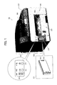
- FIG. 1 is a diagram illustrating exterior appearance of a multifunctional inkjet printer (hereinafter referred to as MFP) 100 in this embodiment.
- the MFP 100 includes a scanner unit 301 and a printer unit 302, and the MFP 100 includes functions such as a copy function, print function, facsimile function, and a function of printing data stored in an external storage (e.g., a USB memory and a digital camera) directly.
- an external storage e.g., a USB memory and a digital camera
- the printer unit 302 includes space 303 where ink cartridges are inserted, a paper feed tray 304, a paper output tray 305, a control panel 307, and a liquid crystal panel 308.
- the MFP 100 in this embodiment can select a large capacity battery that consists of lithium-ion batteries or nickel-hydrogen battery etc. as power source in addition to commercial power supplied by an alternating current adapter (not shown in figures).
- a dedicated battery pack 310 is used as the high-capacity battery. If the battery back 310 is mounted from the front surface of the printer unit 302, it is possible to supply power from terminals 312 to the apparatus.
- the battery 310 there are LEDs 323 that visually indicates charge remaining on the battery 310 provided on the front surface of the printer unit 302.
- the LEDs 323 do not light up in case of energy saving mode and the power is turned off unless a switch 321 is pressed (described in detail later).
- the LEDs 323 function as a status indicator, and the switch 321 functions as an instruction acceptance unit.
- the LEDs 323 and the switch 321 are incorporated as one unit.
- the MFP is described from its exterior appearance above.
- the internal configuration of the printer unit 302 of the MFP 100 is described below with reference to FIGS. 2A and 2B .
- FIG. 2A is a diagram illustrating the side view of the internal configuration of the MFP 100
- FIG. 2B is a diagram illustrating the top view of the internal configuration of the MFP 100.
- a guide rod 31 and a stay 32 bridge a left side panel 21A and a right side panel 21B.
- a carriage 33 is supported by the guide rod 31 and the stay 32 in the main scanning direction. The carriage 33 can move in the direction shown by the arrow (in the main scanning direction) driven by the main scanning motor (not shown in figures).
- a controller controls the ink droplets ejection of the recording heads 34 via a harness 22.
- the carriage 33 includes four sub-tanks 35 for supplying ink to each of the recording heads 34.
- Ink is supplied from ink cartridges 10 (10k, 10c, 10m, and 10y) loaded on a cartridge loading unit 4 to the corresponding sub-tank 35 via an ink feeding tube 36.
- the paper feeding unit for feeding paper 42 from the paper feed tray 304 includes a semicircle paper feed roller 43 for feeding the paper 42 loaded on a paper loading plate 41 one by one separately, a separating pad 44 located facing to the paper feed roller 43.
- the paper conveyance belt 51 is entrained around a carrying roller 52 and a tension roller 53, and the paper conveyance belt 51 moves in the direction shown by the arrow (in the sub-scanning direction) by driving the carrying roller with a sub-scanning motor (not shown in figures). In this case, the surface of the paper carrying belt is charged by a charging roller 56.
- the paper 42 fed from the paper feed unit sticks to the paper conveyance belt 51 electrostatically, and the paper 42 is transferred under the recording heads 34.
- the carriage 33 drives the recording heads 34 in accordance with the image signal moving in the main scanning direction.
- the ink droplets are ejected on the still paper 42 in accordance with the image signal. Consequently, in case of finishing recording for one line, the paper 42 is transferred at predetermined distance in the sub-scanning direction, and the recording for next line is performed. Subsequently, similar steps are repeated. Finally, the recording operation finishes in response to receiving an end signal or a signal that indicates that the trailing edge of the paper 42 reaches the recording area.
- the paper ejection unit for ejecting the paper 42 after finishing recording includes a separation claw 61 for separating the paper 42 from the paper conveyance belt 51, a paper ejection roller 62, and an ejecting roller 63, and the ejected paper 42 is placed in stock on the paper ejection tray 305.
- the maintenance and recovery unit 81 includes caps 82a, 82b, 82c, and 82d for capping each nozzle surface of the recording heads 34, a wiper blade 83 for wiping the nozzle surface, and a dummy ejection receiver 84 for receiving ink droplets ejected during the dummy ejections for ejecting thickened recording liquid. After finishing recording (printing), the carriage 33 moves to the side of the maintenance and recovery unit 81.
- a controller 200 controls the whole part of the MFP 100 and includes a controlling unit that controls transition to operating modes such as energy saving mode and normal mode.
- a controller 200 includes a CPU 201, a ROM 202, a RAM 203, a NVRAM 204, and an ASIC 205.
- the CPU 201 controls carrying the paper 42 and moving the recording heads 34 etc.
- the ROM 202 stores programs etc. executed by the CPU 201.
- the RAM 203 stores image data etc. temporarily, and the NVRAM 204 keeps data during the power-off.
- the ASIC 205 performs various image processing on the image data and processes input/output signals for controlling the whole part of the apparatus. In addition, as described later, the ASIC 205 detects external communication during energy saving mode and recovers the system in response to the external communication.
- the controller 200 further includes a host I/F 206 that transmits/receives print data from/to a printer driver 220 in the host, a print controller 207, a main scanning motor driver 208, a sub-scanning motor driver 210, an AC bias supplier 209, and an I/O 211 that inputs signals from a linear encoder 254 and a wheel encoder 256.
- Examples of the host I/F 206 are Universal Serial Bus (USB) and Network Interface Card (NIC) etc.
- the print controller 207 generates driving data for driving the recording head 34 and output the driving data to a head driver 252.
- the main scanning motor driver 208 drives a main scanning motor 253, and the sub-scanning motor driver 210 drives a sub-scanning motor 255.
- the AC bias supplier 209 applies high voltage to the charging roller 56.
- the controller 200 is connected to the control panel 307 that inputs and displays data necessary for the apparatus and a power supply board 120 that supplies power to the apparatus.
- the system configuration of the MFP 100 is described above.
- the function of the power supply board 120 that controls operating power of the MFP 100 is described below.
- FIG. 4 is a diagram illustrating the configuration of the power supply board 120 included in the MFP 100.
- the power supply board 120 includes a switching circuit 112, DC/DC converters 113 and 114, and a remaining charge detection circuit 115.
- the switching circuit 112 consists of a FET and a control IC.
- the switching circuit charges the battery 310 using the commercial power supplied via the AC adapter 111 and selects either the AC adapter 111 (i.e., the commercial power) or the battery 310 as the driving power.
- the DC/DC converters 113 and 114 generate necessary DC voltage from a single power source supplied from a power supply (either the AC adapter or the battery 310) and supply the DC voltage to the controller 200.
- a comparator IC compares voltage of the battery 310 with reference voltages configured using voltage dividing resistors and detects the voltage level of the battery 310 in multiple stages.
- the detected voltage level is not limited to five-staged as shown in FIG. 1 , and it is possible to configure arbitrary levels.
- the remaining charge detection circuit 115 lights LEDs corresponding to the detected voltage level among multiple LEDs 323.
- Examples of the status indicator are a unit that indicates the status of the charge remaining stepwise by the number of luminous light emitting elements and a unit that indicates the status of the charge remaining using the light emitting status such as blinking of one or more light emitting elements with single-color or multicolor or using the combination of them.
- the remaining charge detection circuit 115 If the detected voltage level is lower than the second lowest level, the remaining charge detection circuit 115 outputs "a battery low signal” to the controller 200 and notifies the controller 200 that the charge remaining on the battery 310 is getting low. In addition, if the detected voltage level is lower than the lowest level (corresponding to the LED 5), the remaining charge detection circuit 115 outputs "a dead battery signal” to the controller 200 and notifies the controller 200 that the battery 310 is out of power. It should be noted that it is not always necessary to associate the voltage levels that output "the battery low signal” and “the dead battery signal” with the voltage levels that illuminates the LEDs 323, and it is possible to configure unique levels for those voltage levels.
- the remaining charge detection circuit 115 after receiving a power supply control signal from the controller 200 via a signal line 116, the remaining charge detection circuit 115 further controls lighting of the LEDs 323 that indicates the charge remaining of the battery.
- the remaining charge detection circuit is described in detail later with reference to FIGS. 8 and 9 . Power supply control is described below.
- the control IC in the switching circuit 112 acquires power supply information in response to turning on the apparatus.
- the power supply information includes whether or not the AC adapter 111 is connected and the battery 310 is connected.
- the switching circuit 112 selects the AC adapter 111 as the power supply source first. Subsequently, the switching circuit 112 selects either the AC adapter 111 or the battery 310 as the power supply source sequentially in accordance with the instruction from the controller 200. In addition, in case of detecting that either one of the two power supplies is disconnected, the switching circuit 112 selects the connected power supply as the power supply source immediately. For example, if the plug of the AC adapter 111 is disconnected or the battery 310 is disconnected, it is detected that it is not connected.
- the battery usage mode if both the commercial power and the battery are available as the power supply, the battery is used preferentially in a predetermined time slot.
- the MFP 100 in configuring the battery usage mode, accepts input for following three items by user operation:
- FIG. 5 is a diagram illustrating an UI screen for configuring a battery usage mode that a printer driver provides
- the configuration information regarding the battery usage mode is stored in the NVRAM 204 included in the controller 200.
- the battery usage mode is implemented by executing a dedicated program stored in the ROM 202 by the CPU 201.
- the battery usage mode that the controller 200 implements is described below with reference to the flowchart shown in FIG. 6 .
- the controller 200 After turning on the main power of the MFP 100, the controller 200 starts up in response to power from the power supply board 120, and the controller 200 starts performing the following steps. After starting up, the controller 200 first refers to the configuration information stored in the NVRAM 204 and determines whether or not the battery usage mode is to be used in S101. As a result, step S101 is repeated as long as the battery usage mode is not to be used (NO in S101). By contrast, if the battery usage mode is to be used (YES in S101), the process proceeds to S102.
- the controller 200 checks the status of the power supply as described below. First, the controller 200 checks the power supply information (whether or not the AC adapter 111 is connected and whether or not the battery 310 is connected) at the switching circuit 112 in the power supply board 120. In response to the query, whether or not the AC adapter 111 is connected and whether or not the battery 310 is connected is detected from the power supply information provided by the switching circuit 112. In addition, it is detected whether or not there is “the battery low signal” and "the dead battery signal” input from the remaining charge detection circuit 115 in the power supply board 120.
- the precondition to enter the battery usage mode is that both the AC adapter 111 and the battery 310 are available as the power supply.
- the condition to enter the battery usage mode is that both the AC adapter 111 and the battery 310 are connected in the state that can supply power and the charge remaining on the battery 310 is enough (more specifically, neither "the battery low signal” nor "the dead battery signal” is detected).
- the improper termination flag is invalid in S104. If the improper termination flag is valid (NO in S104), the process returns to S101 and the steps described above are repeated.
- the "improper termination flag" is for managing history that the active power source is changed from the battery to the commercial power before the scheduled battery usage period expires. In the battery usage period while the battery usage mode is activated, the improper termination flag is enabled in response to receiving "the battery low signal" from the remaining charge detection circuit 115, and the improper termination flag is reset when the battery usage period expires.
- S105 After comparing the current date/time with the configuration information stored in the NVRAM 204 (date and time slot when the battery usage mode is activated), it is determined whether or not the current time belongs to the time slot when the battery usage mode is activated (hereinafter referred to as battery usage period).
- the process returns to S101, and the steps described above are repeated.
- the process proceeds to S106, and the power supply board 120 is instructed to select the battery 310 as the power supply. While the battery usage mode is activated, it is maintained to select the battery 310 as the driving power.
- the process proceeds to S107. After comparing the current time with the configured battery usage period, it is determined whether or not the current time belongs to the battery usage period again. As a result, if it is determined that the current time belongs to the battery usage period (YES in S107), the process proceeds to S108, and it is determined whether or not the charge remaining on the battery is decreasing. As a result, as long as "the battery low signal" is not input (NO in S108), the process returns to S101, and the steps described above are repeated.
- S2 The battery usage mode is idling.
- S3 The battery usage mode is in use.
- S1 indicates that it is unnecessary to use the battery usage mode or the condition to perform the battery usage mode is not satisfied even if it is necessary to perform the battery usage mode.
- S1 if it is changed that the battery usage mode is necessary to use and the conditions for entering the second battery usage mode are satisfied, the state transitions to S2.
- the battery usage period has not arrived yet in case the battery usage mode is set to be used and the preconditions for using the battery are satisfied. Therefore, the commercial power is selected as the power supply in S2, and the battery is charged during S2. If the battery usage mode is set not to be used in S2, the state transitions to S 1.
- the battery usage period has arrived already in case the battery usage mode is set to be used and the preconditions for using the battery are satisfied. If the start time of the battery usage period has arrived, the state transitions from S3 to S2, and the power supply changes from the battery to the commercial power. By contrast, if the end time of the battery usage period has arrived, the state transitions from S2 to S3, and the power supply changes from the commercial power to the battery. If the battery usage mode is set not to be used in S3, the state transitions to S1.
- S4 is a state that the battery usage mode ends inappropriately in response to a case that the charge remaining of the battery reaches a predetermined threshold in S3.
- the power supply is set to the commercial power without using the battery. If the battery usage mode is set not to be used in S4, the state transitions to S1.
- the battery usage mode in this embodiment can contribute to leveling electricity demand peaks in offices.
- the time slot during daytime hours is configured as the battery usage period for all of or part of the multiple MFP 100 located in the offices, it is possible to reduce the commercial power consumption during daytime hours when electric power demand reaches a peak, and the reduced power consumption shifts to nighttime hours with lower electric power demand. Consequently, peaks in electric power demand can be leveled.
- the battery usage mode in the MFP 100 is described above.
- a transition control among operating modes in the MFP 100 and display of battery power in accordance with the operating modes is described below with reference to FIGS. 8 and 9 .
- FIGS. 8A and 8B are diagrams illustrating a configuration of the remaining charge detection circuit 115 in the power supply board 120 included in the MFP 100 in this embodiment.
- the remaining charge detection circuit 115 includes a LED light control circuit 117 that controls lighting a LED among five LEDs 323 corresponding to the detected voltage level.
- the controller 200 controls power supply to the LED light control circuit 117 in the remaining charge detection circuit 115.
- the remaining charge detection circuit 115 includes a FET switch 118 that either sends or cuts power to the LED light control circuit 117 in accordance with a level of the power supply control signal from the controller 200 via a signal line 116.
- pressing status of the switch 321 in FIG. 1 is sent to the controller 200 once, and electric power to the LED light control circuit 117 is either sent or cut under the control of the power supply control signal by the controller 200.
- the remaining charge detection circuit 115 includes a switch 119 in parallel with the switch that either sends or cuts power to the power supply line in accordance with the power supply control signal from the controller 200.
- the switch 119 either sends or cuts electric power to the power supply line to the LED light control circuit 117 in response to the pressing status of the switch 321 in FIG. 1 .
- the pressing status of the switch 321 in FIG. 1 directly controls opening/closing of the switch 119, and power supply to the LED light control circuit 117 is controlled by either passing or cutting electric power to the two parallel power supply lines.
- electric power to the remaining charge detection circuit 115 is supplied from the battery 310 in order to indicate the charge remaining.
- the LEDs 323 are turned on/off and the battery power is displayed or not displayed by controlling power supply to the LED light control circuit 117 in the remaining charge detection circuit 115. It is possible to select electric power supply to the remaining charge detection circuit 115 either from the commercial power or from the battery in accordance with whether or not "the battery low signal” or "the dead battery signal” exists similar to the selection of the driving power.
- the power supply source to the remaining charge detection circuit 115 is switched from the battery to the commercial power in accordance with the switching of driving power from the battery to the commercial power if the battery power becomes lower than a predetermined threshold value.
- FIG. 9 is a flowchart illustrating a process of controlling energy consumption and indicating charge remaining on the battery executed by the MFP in this embodiment.
- the battery usage mode higher energy-saving level than usual is demanded since it is desirable to extend battery life in order to level power consumption.
- energy-saving control and battery power indicator control described below can be implemented.
- the control process depicted in FIG. 9 starts in response to the MFP 100 transitioning to a normal mode (that displays the control panel, etc., and waits for user operation).
- the controller 200 determines whether or not an event that triggers transition to the energy-saving mode (hereinafter referred to as an energy-saving mode transition event) occurs in S201. In this case, the energy-saving mode transition event occurs if a certain period of time passes in idle status etc.
- the step S201 is repeated until the energy-saving mode transition event occurs (NO in S201). If it is determined that the energy-saving mode transition event occurs (YES in S201), the process proceeds to S202.
- the controller 200 sets the power supply control signal to off level and instructs the remaining charge detection circuit 115 to stop supplying power to the LED light control circuit 117 in S202.
- the remaining charge detection circuit 115 turns off the switch 118 and stops supplying power to the LED light control circuit 117 in S203.
- the controller 200 turns the apparatus into the sleep state except for a part of the ASIC 205 (a communication detection function that detects external communication and a wake-up function that wakes up the apparatus after detecting the external communication, stops supplying power to the most part of the controller 200 except the host I/F 206, the control panel 307, and the engine, and transitions to the energy-saving mode.
- the process branches depending on whether or not the lighting switch 321 is pressed in S205. If the lighting switch is not pressed (NO in S205), the process proceeds to S206. The LED light control circuit 117 is turned off, and the charge remaining is not displayed in S206. Subsequently, the process proceeds to S207. By contrast, if the lighting switch 321 is pressed and it is instructed to display the charge remaining using the LEDs 323 (YES in S205), the process proceeds to S208. The LED light control circuit 117 is turned on, and the charge remaining is displayed in S208. Subsequently, the process proceeds to S207.
- the controller 200 maintains its function to output the power supply signal to the remaining charge detection circuit 115 via the signal line 116 in the energy-saving mode depending on the status of the lighting switch 321.
- the switch 119 in the remaining charge detection circuit 115 is turned on/off depending on the status of the lighting switch 321, and the lighting switch 321 directly controls the power supply status of the LED light control circuit 117.
- the active part of the ASIC 205 determines whether or not an event that triggers returning from the energy-saving mode (hereinafter referred to as a recovery event) has occurred.
- the recovery event occurs in case of detecting external communication such as USB and LAN and detecting that the start button on the control panel is pressed etc. Until the recovery event occurs (NO in S207), the step S207 is repeated. If it is determined that the recovery event occurs (YES in S207), the process proceeds to S209.
- the active part of the ASIC 205 transitions the remaining parts of the ASIC 205 from the sleep status to the normal status, starts supplying power to the parts of the controller 200 that has been stopped supplying power, the control panel 307, and the engine, and transitions to the normal mode.
- the controller 200 turns the power supply control signal to the remaining charge detection circuit 115 into on level and instructs to start supplying power to the LED light control circuit 117.
- the remaining charge detection circuit 115 turns on the switch 118 and starts supplying power to the LED light control circuit 117 in S211.
- the process returns to S201, and the steps described above are repeated.
- the information processing apparatus that use the battery as the driving power, it is possible to display the status of the battery in accordance with the operating modes of the information processing apparatus and reduce power consumption used for displaying the status.
- a multifunctional inkjet printer is used as the information processing apparatus of the present invention.
- the present embodiment is not limited to the case described above, and it is possible to apply the present invention to a single-functional printer that implements the printing function only and various single-functional devices that implement a scanner function, facsimile function, projection function, and camera function.
- the energy saving control described above it is controlled to transition between two modes, one is the energy saving mode, and the other is the normal mode that supplies more power than the energy saving mode and accepts user operation.
- the operating modes in which the MFP 100 can run is not limited to the case described above, and it is possible to set up multiple operating modes in accordance with multilevel power supply.
- STR Suspended To RAM
- the charge remaining of the battery is displayed as displaying the status of the battery.
- it is possible to display other status such as error of the battery, and it is possible to display whatever status of the battery.
- a computer can be used with a computer-readable program, described by object-oriented programming languages such as C++, Java (registered trademark), JavaScript (registered trademark), Perl, Ruby, or legacy programming languages such as machine language, assembler language to control functional units used for the apparatus or system.
- object-oriented programming languages such as C++, Java (registered trademark), JavaScript (registered trademark), Perl, Ruby, or legacy programming languages such as machine language, assembler language to control functional units used for the apparatus or system.
- a particular computer e.g., personal computer, workstation
- at least one or more of the units of apparatus can be implemented as hardware or as a combination of hardware/software combination.
- the computer software can be provided to the programmable device using any storage medium or carrier medium for storing processor-readable code such as a floppy disk, a compact disk read only memory (CD-ROM), a digital versatile disk read only memory (DVD-ROM), DVD recording only/rewritable (DVD-R/RW), electrically erasable and programmable read only memory (EEPROM), erasable programmable read only memory (EPROM), a memory card or stick such as USB memory, a memory chip, a mini disk (MD), a magneto optical disc (MO), magnetic tape, a hard disk in a server, a solid state memory device or the like, but not limited these.
- processor-readable code such as a floppy disk, a compact disk read only memory (CD-ROM), a digital versatile disk read only memory (DVD-ROM), DVD recording only/rewritable (DVD-R/RW), electrically erasable and programmable read only memory (EEPROM), erasable programmable read only
- a processing circuit includes a programmed processor, as a processor includes circuitry.
- a processing circuit also includes devices such as an application specific integrated circuit (ASIC) and conventional circuit components arranged to perform the recited functions.
- ASIC application specific integrated circuit
- the image forming apparatus includes the document holding determination unit only.
- the image forming apparatus includes the document holding determination unit and any one of or any combination of the rangefinder, the user authentication unit, the recovery processor, the print job acquisition unit, the auxiliary parameter setting unit, and the facsimile number setting unit.
- this invention may be implemented as convenient using a conventional general-purpose digital computer programmed according to the teachings of the present specification.
- Appropriate software coding can readily be prepared by skilled programmers based on the teachings of the present disclosure, as will be apparent to those skilled in the software arts.
- the present invention may also be implemented by the preparation of application-specific integrated circuits or by interconnecting an appropriate network of conventional component circuits, as will be readily apparent to those skilled in the relevant art.
Landscapes
- Engineering & Computer Science (AREA)
- Theoretical Computer Science (AREA)
- Signal Processing (AREA)
- Multimedia (AREA)
- General Physics & Mathematics (AREA)
- Physics & Mathematics (AREA)
- General Engineering & Computer Science (AREA)
- Computer Hardware Design (AREA)
- Human Computer Interaction (AREA)
- Accessory Devices And Overall Control Thereof (AREA)
- Charge And Discharge Circuits For Batteries Or The Like (AREA)
- Facsimiles In General (AREA)
- Ink Jet (AREA)
- Power Sources (AREA)
Abstract
Description
- The present invention relates to an information processing apparatus, and more particularly, a battery-powered information processing apparatus, and a control method performed by the information processing apparatus.
- Conventionally, image forming apparatuses that are equipped with a secondary battery (hereinafter simply "battery") are known (e.g.,
JP-2008-068548-A JP-08-171360-A - Recently, saving energy in information apparatuses is demanded for various reasons. However, conventionally, the emitting element is always turned on in order to indicate statuses such as the charge remaining of the battery etc., and that prevents from saving energy. Especially, saving energy is highly demanded in case of using the battery as power source.
- An object of the present invention is to provide a novel information processing apparatus that uses the battery as power source, which indicates status of the battery in accordance with an operation mode of the information processing apparatus, while reducing power consumption for indicating status.
- An example embodiment of the present invention provides a novel information processing apparatus that includes a status indicator that displays the status of a battery, a controller that controls an operating mode of the information processing apparatus and power supply to the status indicator, the operating mode at least including an energy saving mode, and an instruction acceptance unit that accepts user instruction for displaying the status of the battery using the status indicator. The controller stops power supply to the status indicator when the information processing apparatus transitions to an energy saving mode, and, in the energy saving mode, starts power supply to the status indicator in response to the instruction acceptance unit accepting the user instruction for displaying and stops power supply to the status indicator in response to releasing the user instruction for displaying.
- Further example embodiments of the present invention provide a control method for the information processing apparatus.
- A more complete appreciation of the disclosure and many of the attendant advantages thereof will be readily obtained as the same becomes better understood by reference to the following detailed description when considered in conjunction with the accompanying drawings.
-
FIG. 1 is a diagram illustrating exterior appearance of a multifunctional peripheral (MFP) as an embodiment of the present invention. -
FIGS. 2A and2B are diagrams illustrating an internal configuration of a printer unit of the MFP as an embodiment of the present invention. -
FIG. 3 is a diagram illustrating a system configuration of the MFP as an embodiment of the present invention. -
FIG. 4 is a diagram illustrating a configuration of a power supply board included in the MFP as an embodiment of the present invention. -
FIG. 5 is a diagram illustrating a screen for configuring a battery usage mode that a printer driver provides as an embodiment of the present invention. -
FIG. 6 is a flowchart illustrating a process performed by the MFP as an embodiment of the present invention. -
FIG. 7 is a diagram illustrating state transition of the battery usage mode as an embodiment of the present invention. -
FIGS. 8A and 8B are diagrams illustrating a configuration of a remaining charge detection circuit in the power supply board included in the MFP as an embodiment of the present invention. -
FIG. 9 is a flowchart illustrating a process of controlling energy consumption and indicating charge remaining on the battery executed by the MFP as an embodiment of the present invention. - In describing preferred embodiments illustrated in the drawings, specific terminology is employed for the sake of clarity. However, the disclosure of this patent specification is not intended to be limited to the specific terminology so selected, and it is to be understood that each specific element includes all technical equivalents that have the same function, operate in a similar manner, and achieve a similar result.
- In the following embodiment, a
multifunctional inkjet printer 100 is taken as an example of the information processing apparatus. In the figures that are referred to below, the same symbols are used for the same elements and redundant descriptions omitted. -
FIG. 1 is a diagram illustrating exterior appearance of a multifunctional inkjet printer (hereinafter referred to as MFP) 100 in this embodiment. The MFP 100 includes ascanner unit 301 and aprinter unit 302, and the MFP 100 includes functions such as a copy function, print function, facsimile function, and a function of printing data stored in an external storage (e.g., a USB memory and a digital camera) directly. - The
printer unit 302 includesspace 303 where ink cartridges are inserted, apaper feed tray 304, apaper output tray 305, acontrol panel 307, and aliquid crystal panel 308. - Here, the
MFP 100 in this embodiment can select a large capacity battery that consists of lithium-ion batteries or nickel-hydrogen battery etc. as power source in addition to commercial power supplied by an alternating current adapter (not shown in figures). InFIG. 1 , adedicated battery pack 310 is used as the high-capacity battery. If thebattery back 310 is mounted from the front surface of theprinter unit 302, it is possible to supply power fromterminals 312 to the apparatus. - Regarding the battery back 310 (hereinafter referred to as the battery 310), there are
LEDs 323 that visually indicates charge remaining on thebattery 310 provided on the front surface of theprinter unit 302. In order to reduce power consumption, theLEDs 323 do not light up in case of energy saving mode and the power is turned off unless aswitch 321 is pressed (described in detail later). TheLEDs 323 function as a status indicator, and theswitch 321 functions as an instruction acceptance unit. Preferably, theLEDs 323 and theswitch 321 are incorporated as one unit. By pressing aswitch 322, the surroundings of thepaper ejection tray 305 are illuminated by a LED lightning (not shown in figures). - The MFP is described from its exterior appearance above. The internal configuration of the
printer unit 302 of theMFP 100 is described below with reference toFIGS. 2A and2B . -
FIG. 2A is a diagram illustrating the side view of the internal configuration of theMFP 100, andFIG. 2B is a diagram illustrating the top view of the internal configuration of theMFP 100. - A
guide rod 31 and a stay 32 bridge aleft side panel 21A and aright side panel 21B. Acarriage 33 is supported by theguide rod 31 and thestay 32 in the main scanning direction. Thecarriage 33 can move in the direction shown by the arrow (in the main scanning direction) driven by the main scanning motor (not shown in figures). - In the
carriage 33, fourrecording heads 34 that eject ink droplets in yellow (Y), cyan (C), magenta (M), and black (K) are mounted perpendicular to the main scanning direction, and a controller (not shown in figures) controls the ink droplets ejection of therecording heads 34 via aharness 22. - Further, the
carriage 33 includes foursub-tanks 35 for supplying ink to each of therecording heads 34. Ink is supplied from ink cartridges 10 (10k, 10c, 10m, and 10y) loaded on acartridge loading unit 4 to thecorresponding sub-tank 35 via anink feeding tube 36. - The paper feeding unit for
feeding paper 42 from thepaper feed tray 304 includes a semicirclepaper feed roller 43 for feeding thepaper 42 loaded on apaper loading plate 41 one by one separately, a separatingpad 44 located facing to thepaper feed roller 43. A guidingmember 45, acounter roller 46, acarrying guide member 47, apress member 48, ahead press roller 49, and apaper conveyance belt 51 located facing to therecording heads 34. - The
paper conveyance belt 51 is entrained around acarrying roller 52 and atension roller 53, and thepaper conveyance belt 51 moves in the direction shown by the arrow (in the sub-scanning direction) by driving the carrying roller with a sub-scanning motor (not shown in figures). In this case, the surface of the paper carrying belt is charged by acharging roller 56. Thepaper 42 fed from the paper feed unit sticks to thepaper conveyance belt 51 electrostatically, and thepaper 42 is transferred under therecording heads 34. - In response to the
paper 42 transferred under therecording heads 34, thecarriage 33 drives therecording heads 34 in accordance with the image signal moving in the main scanning direction. As a result, the ink droplets are ejected on the stillpaper 42 in accordance with the image signal. Consequently, in case of finishing recording for one line, thepaper 42 is transferred at predetermined distance in the sub-scanning direction, and the recording for next line is performed. Subsequently, similar steps are repeated. Finally, the recording operation finishes in response to receiving an end signal or a signal that indicates that the trailing edge of thepaper 42 reaches the recording area. The paper ejection unit for ejecting thepaper 42 after finishing recording includes aseparation claw 61 for separating thepaper 42 from thepaper conveyance belt 51, apaper ejection roller 62, and an ejectingroller 63, and the ejectedpaper 42 is placed in stock on thepaper ejection tray 305. - On the right edge of paper surface in the main scanning direction of the
carriage 33, there is a maintenance andrecovery unit 81 for maintaining the nozzle status of the recording heads 34. The maintenance andrecovery unit 81 includescaps wiper blade 83 for wiping the nozzle surface, and adummy ejection receiver 84 for receiving ink droplets ejected during the dummy ejections for ejecting thickened recording liquid. After finishing recording (printing), thecarriage 33 moves to the side of the maintenance andrecovery unit 81. - The internal configuration of the
MFP 100 in this embodiment is described above. The system configuration of the MFP is described below with reference toFIG. 3 . Acontroller 200 controls the whole part of theMFP 100 and includes a controlling unit that controls transition to operating modes such as energy saving mode and normal mode. - A
controller 200 includes aCPU 201, aROM 202, aRAM 203, aNVRAM 204, and anASIC 205. TheCPU 201 controls carrying thepaper 42 and moving the recording heads 34 etc. TheROM 202 stores programs etc. executed by theCPU 201. TheRAM 203 stores image data etc. temporarily, and theNVRAM 204 keeps data during the power-off. TheASIC 205 performs various image processing on the image data and processes input/output signals for controlling the whole part of the apparatus. In addition, as described later, theASIC 205 detects external communication during energy saving mode and recovers the system in response to the external communication. - The
controller 200 further includes a host I/F 206 that transmits/receives print data from/to aprinter driver 220 in the host, aprint controller 207, a mainscanning motor driver 208, asub-scanning motor driver 210, anAC bias supplier 209, and an I/O 211 that inputs signals from alinear encoder 254 and awheel encoder 256. Examples of the host I/F 206 are Universal Serial Bus (USB) and Network Interface Card (NIC) etc. - The
print controller 207 generates driving data for driving therecording head 34 and output the driving data to ahead driver 252. The mainscanning motor driver 208 drives amain scanning motor 253, and thesub-scanning motor driver 210 drives asub-scanning motor 255. TheAC bias supplier 209 applies high voltage to the chargingroller 56. In addition, thecontroller 200 is connected to thecontrol panel 307 that inputs and displays data necessary for the apparatus and apower supply board 120 that supplies power to the apparatus. - The system configuration of the
MFP 100 is described above. The function of thepower supply board 120 that controls operating power of theMFP 100 is described below. -
FIG. 4 is a diagram illustrating the configuration of thepower supply board 120 included in theMFP 100. Thepower supply board 120 includes aswitching circuit 112, DC/DC converters charge detection circuit 115. - The
switching circuit 112 consists of a FET and a control IC. The switching circuit charges thebattery 310 using the commercial power supplied via theAC adapter 111 and selects either the AC adapter 111 (i.e., the commercial power) or thebattery 310 as the driving power. - The DC/
DC converters controller 200. - In the remaining
charge detection circuit 115, a comparator IC compares voltage of thebattery 310 with reference voltages configured using voltage dividing resistors and detects the voltage level of thebattery 310 in multiple stages. The detected voltage level is not limited to five-staged as shown inFIG. 1 , and it is possible to configure arbitrary levels. The remainingcharge detection circuit 115 lights LEDs corresponding to the detected voltage level amongmultiple LEDs 323. Examples of the status indicator are a unit that indicates the status of the charge remaining stepwise by the number of luminous light emitting elements and a unit that indicates the status of the charge remaining using the light emitting status such as blinking of one or more light emitting elements with single-color or multicolor or using the combination of them. - If the detected voltage level is lower than the second lowest level, the remaining
charge detection circuit 115 outputs "a battery low signal" to thecontroller 200 and notifies thecontroller 200 that the charge remaining on thebattery 310 is getting low. In addition, if the detected voltage level is lower than the lowest level (corresponding to the LED 5), the remainingcharge detection circuit 115 outputs "a dead battery signal" to thecontroller 200 and notifies thecontroller 200 that thebattery 310 is out of power. It should be noted that it is not always necessary to associate the voltage levels that output "the battery low signal" and "the dead battery signal" with the voltage levels that illuminates theLEDs 323, and it is possible to configure unique levels for those voltage levels. - In this embodiment, after receiving a power supply control signal from the
controller 200 via asignal line 116, the remainingcharge detection circuit 115 further controls lighting of theLEDs 323 that indicates the charge remaining of the battery. The remaining charge detection circuit is described in detail later with reference toFIGS. 8 and9 . Power supply control is described below. - The control IC in the
switching circuit 112 acquires power supply information in response to turning on the apparatus. The power supply information includes whether or not theAC adapter 111 is connected and thebattery 310 is connected. - If both of the two power supplies are connected when the apparatus is turned on, the
switching circuit 112 selects theAC adapter 111 as the power supply source first. Subsequently, theswitching circuit 112 selects either theAC adapter 111 or thebattery 310 as the power supply source sequentially in accordance with the instruction from thecontroller 200. In addition, in case of detecting that either one of the two power supplies is disconnected, theswitching circuit 112 selects the connected power supply as the power supply source immediately. For example, if the plug of theAC adapter 111 is disconnected or thebattery 310 is disconnected, it is detected that it is not connected. - The function that the
power supply board 120 performs is described above. "A battery usage mode" that theMFP 100 in this embodiment includes is described below. - In this embodiment, in "the battery usage mode", if both the commercial power and the battery are available as the power supply, the battery is used preferentially in a predetermined time slot.
- In this embodiment, in configuring the battery usage mode, the
MFP 100 accepts input for following three items by user operation: - (1) Whether or not the battery usage mode is to be used
- (2) Date when the battery usage mode is enabled (every day/day setting/date setting etc.)
- (3) Time slot when the battery usage mode is used (start time/end time)
- In this embodiment, the above items can be input from the
control panel 307. Alternatively, it is possible to accept input via a printer driver in a personal computer (PC) connected to theMFP 100.FIG. 5 is a diagram illustrating an UI screen for configuring a battery usage mode that a printer driver provides - The configuration information regarding the battery usage mode is stored in the
NVRAM 204 included in thecontroller 200. The battery usage mode is implemented by executing a dedicated program stored in theROM 202 by theCPU 201. The battery usage mode that thecontroller 200 implements is described below with reference to the flowchart shown inFIG. 6 . - In
FIG. 6 , after turning on the main power of theMFP 100, thecontroller 200 starts up in response to power from thepower supply board 120, and thecontroller 200 starts performing the following steps. After starting up, thecontroller 200 first refers to the configuration information stored in theNVRAM 204 and determines whether or not the battery usage mode is to be used in S101. As a result, step S101 is repeated as long as the battery usage mode is not to be used (NO in S101). By contrast, if the battery usage mode is to be used (YES in S101), the process proceeds to S102. - In S102, the
controller 200 checks the status of the power supply as described below. First, thecontroller 200 checks the power supply information (whether or not theAC adapter 111 is connected and whether or not thebattery 310 is connected) at theswitching circuit 112 in thepower supply board 120. In response to the query, whether or not theAC adapter 111 is connected and whether or not thebattery 310 is connected is detected from the power supply information provided by the switchingcircuit 112. In addition, it is detected whether or not there is "the battery low signal" and "the dead battery signal" input from the remainingcharge detection circuit 115 in thepower supply board 120. - Next, in S103, after specifying whether or not the
AC adapter 111 is connected, whether or not thebattery 310 is connected, and the status of the power supply from whether or not there is the input signal from the remainingcharge detection circuit 115, it is determined whether or not the status of the power supply meets the necessary precondition to enter the battery usage mode. - Here, in this embodiment, the precondition to enter the battery usage mode is that both the
AC adapter 111 and thebattery 310 are available as the power supply. Specifically, the condition to enter the battery usage mode is that both theAC adapter 111 and thebattery 310 are connected in the state that can supply power and the charge remaining on thebattery 310 is enough (more specifically, neither "the battery low signal" nor "the dead battery signal" is detected). - In S103, as long as it is determined that the status of the power supply does not satisfy the condition to perform the battery usage mode (NO in S103), the process returns to S101 and the steps described above are repeated. If it is determined that the status of the power supply meets the necessary preconditions to enter the battery usage mode (YES in S103), the process proceeds to S104.
- It is determined whether or not the improper termination flag is invalid in S104. If the improper termination flag is valid (NO in S104), the process returns to S101 and the steps described above are repeated. In this embodiment, the "improper termination flag" is for managing history that the active power source is changed from the battery to the commercial power before the scheduled battery usage period expires. In the battery usage period while the battery usage mode is activated, the improper termination flag is enabled in response to receiving "the battery low signal" from the remaining
charge detection circuit 115, and the improper termination flag is reset when the battery usage period expires. - By contrast, if it is determined that an improper termination flag is invalid in S104 (YES in S104), the process proceeds to S105. In S105, after comparing the current date/time with the configuration information stored in the NVRAM 204 (date and time slot when the battery usage mode is activated), it is determined whether or not the current time belongs to the time slot when the battery usage mode is activated (hereinafter referred to as battery usage period).
- As a result, if it is determined that the current time does not belong to the battery usage period (NO in S105), the process returns to S101, and the steps described above are repeated. By contrast, if it is determined that the current time belongs to the battery usage period (YES in S105), the process proceeds to S106, and the
power supply board 120 is instructed to select thebattery 310 as the power supply. While the battery usage mode is activated, it is maintained to select thebattery 310 as the driving power. - Next, the process proceeds to S107. After comparing the current time with the configured battery usage period, it is determined whether or not the current time belongs to the battery usage period again. As a result, if it is determined that the current time belongs to the battery usage period (YES in S107), the process proceeds to S108, and it is determined whether or not the charge remaining on the battery is decreasing. As a result, as long as "the battery low signal" is not input (NO in S108), the process returns to S101, and the steps described above are repeated.
- In repeating the steps from S101 to S108 described above, if the current time does not belong to the battery usage period any more (NO in S107), the process proceeds to S110, and the
power supply board 120 is instructed to select theAC adapter 111 as the power supply in S110. - By contrast, in S108, if it is determined that the remaining of the battery is decreasing (i.e., in case of detecting input of "the battery low signal"), after enabling the improper termination flag in S109, the power supply is changed to the
AC adapter 111 immediately in S110. - Next, the configuration of the battery usage mode in this embodiment is described below with reference to the diagram that illustrates state transition shown in
FIG. 7 . As shown inFIG. 7 , in this embodiment, there are four states regarding the battery usage mode as shown below. - S1: The battery usage mode is invalid.
- S2: The battery usage mode is idling.
- S3: The battery usage mode is in use.
- S4: The battery usage mode is terminated improperly.
- Here, S1 indicates that it is unnecessary to use the battery usage mode or the condition to perform the battery usage mode is not satisfied even if it is necessary to perform the battery usage mode. In S1, if it is changed that the battery usage mode is necessary to use and the conditions for entering the second battery usage mode are satisfied, the state transitions to S2.
- In S2, the battery usage period has not arrived yet in case the battery usage mode is set to be used and the preconditions for using the battery are satisfied. Therefore, the commercial power is selected as the power supply in S2, and the battery is charged during S2. If the battery usage mode is set not to be used in S2, the state transitions to
S 1. - In S3, the battery usage period has arrived already in case the battery usage mode is set to be used and the preconditions for using the battery are satisfied. If the start time of the battery usage period has arrived, the state transitions from S3 to S2, and the power supply changes from the battery to the commercial power. By contrast, if the end time of the battery usage period has arrived, the state transitions from S2 to S3, and the power supply changes from the commercial power to the battery. If the battery usage mode is set not to be used in S3, the state transitions to S1.
- S4 is a state that the battery usage mode ends inappropriately in response to a case that the charge remaining of the battery reaches a predetermined threshold in S3. In S4, even if the battery usage period has arrived already in case the battery usage mode is set to be used and the preconditions for using the battery are satisfied, the power supply is set to the commercial power without using the battery. If the battery usage mode is set not to be used in S4, the state transitions to S1.
- As described above, the battery usage mode in this embodiment can contribute to leveling electricity demand peaks in offices. For example, if the time slot during daytime hours is configured as the battery usage period for all of or part of the
multiple MFP 100 located in the offices, it is possible to reduce the commercial power consumption during daytime hours when electric power demand reaches a peak, and the reduced power consumption shifts to nighttime hours with lower electric power demand. Consequently, peaks in electric power demand can be leveled. - The battery usage mode in the
MFP 100 is described above. A transition control among operating modes in theMFP 100 and display of battery power in accordance with the operating modes is described below with reference toFIGS. 8 and9 . -
FIGS. 8A and 8B are diagrams illustrating a configuration of the remainingcharge detection circuit 115 in thepower supply board 120 included in theMFP 100 in this embodiment. As shown inFIGS. 8A and 8B , the remainingcharge detection circuit 115 includes a LEDlight control circuit 117 that controls lighting a LED among fiveLEDs 323 corresponding to the detected voltage level. - In
FIG. 8A , thecontroller 200 controls power supply to the LEDlight control circuit 117 in the remainingcharge detection circuit 115. In the embodiment shown inFIG. 8A , the remainingcharge detection circuit 115 includes aFET switch 118 that either sends or cuts power to the LEDlight control circuit 117 in accordance with a level of the power supply control signal from thecontroller 200 via asignal line 116. In the embodiment shown inFIG. 8A , pressing status of theswitch 321 inFIG. 1 is sent to thecontroller 200 once, and electric power to the LEDlight control circuit 117 is either sent or cut under the control of the power supply control signal by thecontroller 200. - By contrast, in the embodiment shown in
FIG. 8B , the remainingcharge detection circuit 115 includes aswitch 119 in parallel with the switch that either sends or cuts power to the power supply line in accordance with the power supply control signal from thecontroller 200. Theswitch 119 either sends or cuts electric power to the power supply line to the LEDlight control circuit 117 in response to the pressing status of theswitch 321 inFIG. 1 . In the embodiment shown inFIG. 8B , the pressing status of theswitch 321 inFIG. 1 directly controls opening/closing of theswitch 119, and power supply to the LEDlight control circuit 117 is controlled by either passing or cutting electric power to the two parallel power supply lines. - Preferably, since additional circuit designing is needed considering sneak current, etc., and since costs increase by adding parts if the commercial power supplies electric power to the remaining
charge detection circuit 115, electric power to the remainingcharge detection circuit 115 is supplied from thebattery 310 in order to indicate the charge remaining. TheLEDs 323 are turned on/off and the battery power is displayed or not displayed by controlling power supply to the LEDlight control circuit 117 in the remainingcharge detection circuit 115. It is possible to select electric power supply to the remainingcharge detection circuit 115 either from the commercial power or from the battery in accordance with whether or not "the battery low signal" or "the dead battery signal" exists similar to the selection of the driving power. In specific embodiments, the power supply source to the remainingcharge detection circuit 115 is switched from the battery to the commercial power in accordance with the switching of driving power from the battery to the commercial power if the battery power becomes lower than a predetermined threshold value. -
FIG. 9 is a flowchart illustrating a process of controlling energy consumption and indicating charge remaining on the battery executed by the MFP in this embodiment. In this embodiment, in the battery usage mode, higher energy-saving level than usual is demanded since it is desirable to extend battery life in order to level power consumption. As a result, while it is not limited, preferably, in the battery usage mode that the battery is selected as the driving power and the commercial power is attached, energy-saving control and battery power indicator control described below can be implemented. - The control process depicted in
FIG. 9 starts in response to theMFP 100 transitioning to a normal mode (that displays the control panel, etc., and waits for user operation). Thecontroller 200 determines whether or not an event that triggers transition to the energy-saving mode (hereinafter referred to as an energy-saving mode transition event) occurs in S201. In this case, the energy-saving mode transition event occurs if a certain period of time passes in idle status etc. The step S201 is repeated until the energy-saving mode transition event occurs (NO in S201). If it is determined that the energy-saving mode transition event occurs (YES in S201), the process proceeds to S202. - In order to transition to the energy-saving mode, the
controller 200 sets the power supply control signal to off level and instructs the remainingcharge detection circuit 115 to stop supplying power to the LEDlight control circuit 117 in S202. In response to the change of the power supply control signal by thecontroller 200, the remainingcharge detection circuit 115 turns off theswitch 118 and stops supplying power to the LEDlight control circuit 117 in S203. Thecontroller 200 turns the apparatus into the sleep state except for a part of the ASIC 205 (a communication detection function that detects external communication and a wake-up function that wakes up the apparatus after detecting the external communication, stops supplying power to the most part of thecontroller 200 except the host I/F 206, thecontrol panel 307, and the engine, and transitions to the energy-saving mode. - In the energy-saving mode, the process branches depending on whether or not the
lighting switch 321 is pressed in S205. If the lighting switch is not pressed (NO in S205), the process proceeds to S206. The LEDlight control circuit 117 is turned off, and the charge remaining is not displayed in S206. Subsequently, the process proceeds to S207. By contrast, if thelighting switch 321 is pressed and it is instructed to display the charge remaining using the LEDs 323 (YES in S205), the process proceeds to S208. The LEDlight control circuit 117 is turned on, and the charge remaining is displayed in S208. Subsequently, the process proceeds to S207. - In this embodiment, it is assumed that the
lighting switch 321 is pressed as the user instruction to display the charge remaining, and it is assumed that thelighting switch 321 is released as the user instruction not to display the charge remaining. Consequently, if thelighting switch 321 is released after being depressed, the LEDlight control circuit 117 is turned off and the charge remaining is not displayed in S206. InFIG. 8A , thecontroller 200 maintains its function to output the power supply signal to the remainingcharge detection circuit 115 via thesignal line 116 in the energy-saving mode depending on the status of thelighting switch 321. InFIG. 8B , theswitch 119 in the remainingcharge detection circuit 115 is turned on/off depending on the status of thelighting switch 321, and thelighting switch 321 directly controls the power supply status of the LEDlight control circuit 117. - In S207, the active part of the ASIC 205 (the wake-up function) determines whether or not an event that triggers returning from the energy-saving mode (hereinafter referred to as a recovery event) has occurred. In this case, the recovery event occurs in case of detecting external communication such as USB and LAN and detecting that the start button on the control panel is pressed etc. Until the recovery event occurs (NO in S207), the step S207 is repeated. If it is determined that the recovery event occurs (YES in S207), the process proceeds to S209.
- In S209, the active part of the ASIC 205 (the wake-up function) transitions the remaining parts of the
ASIC 205 from the sleep status to the normal status, starts supplying power to the parts of thecontroller 200 that has been stopped supplying power, thecontrol panel 307, and the engine, and transitions to the normal mode. In S210, after returning from the energy-saving mode, thecontroller 200 turns the power supply control signal to the remainingcharge detection circuit 115 into on level and instructs to start supplying power to the LEDlight control circuit 117. In response to the change of the power supply control signal by thecontroller 200, the remainingcharge detection circuit 115 turns on theswitch 118 and starts supplying power to the LEDlight control circuit 117 in S211. Next, the process returns to S201, and the steps described above are repeated. - In the embodiment described above, in the information processing apparatus that use the battery as the driving power, it is possible to display the status of the battery in accordance with the operating modes of the information processing apparatus and reduce power consumption used for displaying the status.
- It is widely needed to reduce electric power in the information processing apparatuses. In the embodiment described above, electric power supply to the status indicator of the battery is appropriately controlled in accordance with the operating modes of the information processing apparatus. It is strongly demanded to extend running time of the battery in the battery usage mode described above. It is possible to reduce unnecessary power consumption and extend the running time of the battery by applying the configuration described above.
- In the embodiment described above, a multifunctional inkjet printer is used as the information processing apparatus of the present invention. However, the present embodiment is not limited to the case described above, and it is possible to apply the present invention to a single-functional printer that implements the printing function only and various single-functional devices that implement a scanner function, facsimile function, projection function, and camera function.
- In the energy saving control described above, it is controlled to transition between two modes, one is the energy saving mode, and the other is the normal mode that supplies more power than the energy saving mode and accepts user operation. However, the operating modes in which the
MFP 100 can run is not limited to the case described above, and it is possible to set up multiple operating modes in accordance with multilevel power supply. For example, it is possible to set up a Suspended To RAM (STR) mode that stores the current operating status in theRAM 203 and stops supplying power to most devices such as theCPU 201 in thecontroller 200 and the HDD, etc., and a controller-off mode that stops supplying power to devices including theRAM 203. In the embodiment described above, the charge remaining of the battery is displayed as displaying the status of the battery. However, in other embodiments, it is possible to display other status such as error of the battery, and it is possible to display whatever status of the battery. - In the above-described example embodiment, a computer can be used with a computer-readable program, described by object-oriented programming languages such as C++, Java (registered trademark), JavaScript (registered trademark), Perl, Ruby, or legacy programming languages such as machine language, assembler language to control functional units used for the apparatus or system. For example, a particular computer (e.g., personal computer, workstation) may control an information processing apparatus or an image processing apparatus such as an image forming apparatus using a computer-readable program, which can execute the above-described processes or steps. In the above-described embodiments, at least one or more of the units of apparatus can be implemented as hardware or as a combination of hardware/software combination. The computer software can be provided to the programmable device using any storage medium or carrier medium for storing processor-readable code such as a floppy disk, a compact disk read only memory (CD-ROM), a digital versatile disk read only memory (DVD-ROM), DVD recording only/rewritable (DVD-R/RW), electrically erasable and programmable read only memory (EEPROM), erasable programmable read only memory (EPROM), a memory card or stick such as USB memory, a memory chip, a mini disk (MD), a magneto optical disc (MO), magnetic tape, a hard disk in a server, a solid state memory device or the like, but not limited these.
- Each of the functions of the described embodiments may be implemented by one or more processing circuits. A processing circuit includes a programmed processor, as a processor includes circuitry. A processing circuit also includes devices such as an application specific integrated circuit (ASIC) and conventional circuit components arranged to perform the recited functions.
- Numerous additional modifications and variations are possible in light of the above teachings. It is therefore to be understood that, within the scope of the appended claims, the disclosure of this patent specification may be practiced otherwise than as specifically described herein. For example, it is possible that the image forming apparatus includes the document holding determination unit only. Alternatively, it is possible that the image forming apparatus includes the document holding determination unit and any one of or any combination of the rangefinder, the user authentication unit, the recovery processor, the print job acquisition unit, the auxiliary parameter setting unit, and the facsimile number setting unit.
- As can be appreciated by those skilled in the computer arts, this invention may be implemented as convenient using a conventional general-purpose digital computer programmed according to the teachings of the present specification. Appropriate software coding can readily be prepared by skilled programmers based on the teachings of the present disclosure, as will be apparent to those skilled in the software arts. The present invention may also be implemented by the preparation of application-specific integrated circuits or by interconnecting an appropriate network of conventional component circuits, as will be readily apparent to those skilled in the relevant art.
Claims (12)
- An information processing apparatus (100), comprising:a status indicator (323) to display status of a battery (310);a controller (200) to control an operating mode of the information processing apparatus (100) and supply power to the status indicator (323); andan instruction acceptance unit (321) to accept user instruction to the status indicator (323) to display the status of the battery (310),wherein the controller (200) turns off the status indicator (323) in transitioning to the energy saving mode, and, while still in the energy saving mode, turns on the status indicator (323) in response to the instruction acceptance unit (321) accepting the user instruction to display and turns off the status indicator (323) in response to the user instruction to display being released.
- The information processing apparatus (100) according to claim 1, further comprising a switching unit (112) to select either the battery (310) or commercial power as driving power,
wherein the controller (200) supplies power to the status indicator (323) if the battery (310) is selected as the driving power and the commercial power is connected to the information processing apparatus. - The information processing apparatus (100) according to any one of claims 1 and 2, wherein the controller (200) turns on the status indicator (323) in transitioning to a predetermined mode that supplies more power than the energy saving mode, and the status indicator (323) displays the status of the battery (310) in the predetermined mode regardless of the instruction accepted at the instruction acceptance unit (321).
- The information processing apparatus (100) according to any one of claims 1 to 3, wherein the energy saving mode is a mode in which the controller (200) at least maintains a function that detects an external communication and a function that wakes up the information processing apparatus (100) in response to detecting the external communication, while stopping power supply to an engine of the information processing apparatus (100).
- The information processing apparatus (100) according to any one of claims 1 to 4, wherein the status indicator (323) includes one or more light emitting elements, which are illuminated so as to reflect charge remaining of the battery (310).
- The information processing apparatus (100) according to any one of claims 1 to 5, wherein the status indicator (323) and the instruction acceptance unit (321) are a single unit.
- The information processing apparatus (100) according to claim 2, wherein the switching unit selects the commercial power to supply electric power to the status indicator (323) in lieu of the battery if the charge remaining on the battery (310) is below a threshold value.
- The information processing apparatus (100) according to any one of claims 2 or 7, wherein, in a case in which both commercial power and battery power are available, the controller (200) selects the battery (310) as the driving power in response to arrival of a predetermined battery usage period and selects the commercial power as the driving power in response to the predetermined battery usage period expiring.
- A method of controlling an information processing apparatus (100), comprising the steps of:displaying, using a status indicator (323) of the information processing apparatus (100), a remaining charge status of a battery (310);controlling an operating mode of the information processing apparatus (100) and power supply to the status indicator (323), the operating mode at least including an energy saving mode;accepting user instruction for displaying the status of the battery (310) using the status indicator (323);stopping power supply to the status indicator (323) in transitioning to the energy saving mode;starting power supply to the status indicator (323) in response to accepting the user instruction for displaying in the energy saving mode; andstopping power supply to the status indicator (323) in response to releasing the user instruction for displaying in the energy saving mode.
- The method of controlling the information processing apparatus (100) according to claim 9, further comprising the steps of:selecting either the battery (310) or commercial power as driving power; andcontrolling supplying power for displaying the status of the battery (310) if the battery (310) is selected as the driving power and the commercial power is connected to the information processing apparatus (100).
- The method of controlling the information processing apparatus (100) according to any one of claims 9 or 10, further comprising the steps of:turning on the status display in transitioning to a predetermined mode that supplies more power than the energy saving mode; anddisplaying the status of the battery (310) in the predetermined mode regardless of the user instruction for displaying.
- The method of controlling the information processing apparatus (100) according to any one of claims 9 to 11, wherein the energy saving mode is a mode in which the information processing apparatus is capable of performing the steps of:detecting an external communication and waking up the information processing apparatus (100) in response to detecting the external communication in the energy saving mode; andstopping supplying power to an engine of the information processing apparatus (100).
Applications Claiming Priority (1)
| Application Number | Priority Date | Filing Date | Title |
|---|---|---|---|
| JP2014000756A JP6281285B2 (en) | 2014-01-07 | 2014-01-07 | Information processing apparatus and control method |
Publications (2)
| Publication Number | Publication Date |
|---|---|
| EP2892009A1 true EP2892009A1 (en) | 2015-07-08 |
| EP2892009B1 EP2892009B1 (en) | 2018-05-16 |
Family
ID=52423569
Family Applications (1)
| Application Number | Title | Priority Date | Filing Date |
|---|---|---|---|
| EP15150066.7A Active EP2892009B1 (en) | 2014-01-07 | 2015-01-05 | Information processing apparatus and control method |
Country Status (5)
| Country | Link |
|---|---|
| US (1) | US9203992B2 (en) |
| EP (1) | EP2892009B1 (en) |
| JP (1) | JP6281285B2 (en) |
| CN (1) | CN104765436B (en) |
| ES (1) | ES2674118T3 (en) |
Families Citing this family (9)
| Publication number | Priority date | Publication date | Assignee | Title |
|---|---|---|---|---|
| JP6452421B2 (en) | 2014-12-08 | 2019-01-16 | キヤノン株式会社 | Image forming apparatus |
| US11176479B2 (en) * | 2015-11-16 | 2021-11-16 | Utopus Insights, Inc. | Cognitive disambiguation for problem-solving tasks involving a power grid using relevance feedback |
| JP6859106B2 (en) * | 2017-01-11 | 2021-04-14 | 株式会社デンソー | Shift-by-wire system |
| US10263443B2 (en) | 2017-01-13 | 2019-04-16 | Hand Held Products, Inc. | Power capacity indicator |
| US10897150B2 (en) | 2018-01-12 | 2021-01-19 | Hand Held Products, Inc. | Indicating charge status |
| JP7443074B2 (en) * | 2020-01-31 | 2024-03-05 | キヤノン株式会社 | Information processing device and control method |
| JP7451217B2 (en) | 2020-02-14 | 2024-03-18 | 新コスモス電機株式会社 | Charging systems and chargers for explosion-proof equipment |
| JP2021133549A (en) * | 2020-02-25 | 2021-09-13 | キヤノン株式会社 | Image formation device, control method, and program |
| JP2023141746A (en) * | 2022-03-24 | 2023-10-05 | キヤノン株式会社 | Printing system and printer control method |
Citations (3)
| Publication number | Priority date | Publication date | Assignee | Title |
|---|---|---|---|---|
| JPH08171360A (en) | 1994-12-16 | 1996-07-02 | Hitachi Koki Co Ltd | Method for displaying remaining capacity of battery |
| JP2008068548A (en) | 2006-09-15 | 2008-03-27 | Ricoh Co Ltd | Image formation system, power supply control method and power supply control program |
| US20100218021A1 (en) * | 2009-02-04 | 2010-08-26 | Mou-Ming Ma | Notebook Computer |
Family Cites Families (10)
| Publication number | Priority date | Publication date | Assignee | Title |
|---|---|---|---|---|
| JP4476523B2 (en) | 2001-09-14 | 2010-06-09 | 株式会社リコー | Camera with built-in flash |
| KR20030057852A (en) * | 2001-12-29 | 2003-07-07 | 삼성전자주식회사 | portable computer and power controlling method thereof |
| US6851781B2 (en) * | 2002-02-20 | 2005-02-08 | Seiko Epson Corporation | Printing apparatus controlling method, printing apparatus controlling program, recording medium for storing printing apparatus controlling program and printing system |
| JP2006059047A (en) * | 2004-08-19 | 2006-03-02 | Fujitsu Ltd | Device for displaying residual amount of battery, and electronic apparatus having the same |
| JP2006315366A (en) * | 2005-05-16 | 2006-11-24 | Canon Inc | Recorder |
| JP2009184160A (en) * | 2008-02-04 | 2009-08-20 | Ricoh Co Ltd | Image forming device |
| JP2009222824A (en) * | 2008-03-14 | 2009-10-01 | Ricoh Co Ltd | Image forming apparatus |
| JP5417240B2 (en) * | 2009-05-07 | 2014-02-12 | 理想科学工業株式会社 | Inkjet printing device |
| JP2011062886A (en) * | 2009-09-16 | 2011-03-31 | Toshiba Tec Corp | Printer, program, and task control method |
| JP5838586B2 (en) * | 2011-05-10 | 2016-01-06 | 株式会社リコー | Image forming apparatus |
-
2014
- 2014-01-07 JP JP2014000756A patent/JP6281285B2/en not_active Expired - Fee Related
- 2014-12-17 US US14/572,968 patent/US9203992B2/en not_active Expired - Fee Related
- 2014-12-23 CN CN201410814865.1A patent/CN104765436B/en not_active Expired - Fee Related
-
2015
- 2015-01-05 EP EP15150066.7A patent/EP2892009B1/en active Active
- 2015-01-05 ES ES15150066.7T patent/ES2674118T3/en active Active
Patent Citations (3)
| Publication number | Priority date | Publication date | Assignee | Title |
|---|---|---|---|---|
| JPH08171360A (en) | 1994-12-16 | 1996-07-02 | Hitachi Koki Co Ltd | Method for displaying remaining capacity of battery |
| JP2008068548A (en) | 2006-09-15 | 2008-03-27 | Ricoh Co Ltd | Image formation system, power supply control method and power supply control program |
| US20100218021A1 (en) * | 2009-02-04 | 2010-08-26 | Mou-Ming Ma | Notebook Computer |
Also Published As
| Publication number | Publication date |
|---|---|
| EP2892009B1 (en) | 2018-05-16 |
| US9203992B2 (en) | 2015-12-01 |
| JP6281285B2 (en) | 2018-02-21 |
| US20150195417A1 (en) | 2015-07-09 |
| ES2674118T3 (en) | 2018-06-27 |
| JP2015128846A (en) | 2015-07-16 |
| CN104765436B (en) | 2018-07-06 |
| CN104765436A (en) | 2015-07-08 |
Similar Documents
| Publication | Publication Date | Title |
|---|---|---|
| EP2892009B1 (en) | Information processing apparatus and control method | |
| US10133291B2 (en) | Image forming apparatus configured for scheduled secondary battery usage period | |
| US9235178B2 (en) | Image processing apparatus | |
| US20190238705A1 (en) | Information processing apparatus, method of controlling information processing apparatus, and non-transitory computer-readable recording medium | |
| JP4605055B2 (en) | Printing device, supply power control device, and computer program | |
| US20110063398A1 (en) | Printer and method of determining print start position | |
| US9256178B2 (en) | Power supply control apparatus, image processing apparatus, power supply control method, and recording medium storing a power supply control program | |
| JP2014226884A (en) | Image forming apparatus and power supply control method | |
| US20110063649A1 (en) | Printer and task control method | |
| US20030048323A1 (en) | Ink-jet printer performing power source control, and control method of ink-jet printer | |
| US20110200377A1 (en) | Printer and printing method | |
| JP4922196B2 (en) | Thermal printer | |
| JP2002044305A (en) | Image forming device | |
| KR102231566B1 (en) | Printing apparatus and control method therefor | |
| US20150306868A1 (en) | Image forming apparatus, image forming method, and recording | |
| JP5379833B2 (en) | Thermal printer and program | |
| US20210242701A1 (en) | Electronic device, printing apparatus, and method for controlling electronic device | |
| JP2006018466A (en) | Electronic apparatus and power supply control method therefor | |
| JP2018081494A (en) | Electronic apparatus, control method, and program | |
| KR102248801B1 (en) | Printing apparatus and control method therefor, and storage medium | |
| JP5031933B2 (en) | Thermal printer | |
| JPH1032668A (en) | Multi-functional office automation device | |
| JP2008140233A (en) | Electronic equipment | |
| JP4779727B2 (en) | Printing device | |
| JP2007245358A (en) | Printer, printing waiting time controller and computer program |
Legal Events
| Date | Code | Title | Description |
|---|---|---|---|
| PUAI | Public reference made under article 153(3) epc to a published international application that has entered the european phase |
Free format text: ORIGINAL CODE: 0009012 |
|
| 17P | Request for examination filed |
Effective date: 20150105 |
|
| AK | Designated contracting states |
Kind code of ref document: A1 Designated state(s): AL AT BE BG CH CY CZ DE DK EE ES FI FR GB GR HR HU IE IS IT LI LT LU LV MC MK MT NL NO PL PT RO RS SE SI SK SM TR |
|
| AX | Request for extension of the european patent |
Extension state: BA ME |
|
| STAA | Information on the status of an ep patent application or granted ep patent |
Free format text: STATUS: EXAMINATION IS IN PROGRESS |
|
| 17Q | First examination report despatched |
Effective date: 20170301 |
|
| REG | Reference to a national code |
Ref country code: DE Ref legal event code: R079 Ref document number: 602015011053 Country of ref document: DE Free format text: PREVIOUS MAIN CLASS: G06K0015000000 Ipc: G06F0001160000 |
|
| GRAP | Despatch of communication of intention to grant a patent |
Free format text: ORIGINAL CODE: EPIDOSNIGR1 |
|
| STAA | Information on the status of an ep patent application or granted ep patent |
Free format text: STATUS: GRANT OF PATENT IS INTENDED |
|
| RIC1 | Information provided on ipc code assigned before grant |
Ipc: G06K 15/00 20060101ALI20171113BHEP Ipc: H04N 1/00 20060101ALI20171113BHEP Ipc: G06F 1/32 20060101ALI20171113BHEP Ipc: G06F 1/16 20060101AFI20171113BHEP |
|
| INTG | Intention to grant announced |
Effective date: 20171208 |
|
| GRAS | Grant fee paid |
Free format text: ORIGINAL CODE: EPIDOSNIGR3 |
|
| GRAA | (expected) grant |
Free format text: ORIGINAL CODE: 0009210 |
|
| STAA | Information on the status of an ep patent application or granted ep patent |
Free format text: STATUS: THE PATENT HAS BEEN GRANTED |
|
| AK | Designated contracting states |
Kind code of ref document: B1 Designated state(s): AL AT BE BG CH CY CZ DE DK EE ES FI FR GB GR HR HU IE IS IT LI LT LU LV MC MK MT NL NO PL PT RO RS SE SI SK SM TR |
|
| REG | Reference to a national code |
Ref country code: GB Ref legal event code: FG4D |
|
| REG | Reference to a national code |
Ref country code: CH Ref legal event code: EP |
|
| REG | Reference to a national code |
Ref country code: IE Ref legal event code: FG4D |
|
| REG | Reference to a national code |
Ref country code: DE Ref legal event code: R096 Ref document number: 602015011053 Country of ref document: DE |
|
| REG | Reference to a national code |
Ref country code: AT Ref legal event code: REF Ref document number: 1000132 Country of ref document: AT Kind code of ref document: T Effective date: 20180615 |
|
| REG | Reference to a national code |
Ref country code: ES Ref legal event code: FG2A Ref document number: 2674118 Country of ref document: ES Kind code of ref document: T3 Effective date: 20180627 |
|
| REG | Reference to a national code |
Ref country code: NL Ref legal event code: FP |
|
| REG | Reference to a national code |
Ref country code: LT Ref legal event code: MG4D |
|
| PG25 | Lapsed in a contracting state [announced via postgrant information from national office to epo] |
Ref country code: SE Free format text: LAPSE BECAUSE OF FAILURE TO SUBMIT A TRANSLATION OF THE DESCRIPTION OR TO PAY THE FEE WITHIN THE PRESCRIBED TIME-LIMIT Effective date: 20180516 Ref country code: FI Free format text: LAPSE BECAUSE OF FAILURE TO SUBMIT A TRANSLATION OF THE DESCRIPTION OR TO PAY THE FEE WITHIN THE PRESCRIBED TIME-LIMIT Effective date: 20180516 Ref country code: NO Free format text: LAPSE BECAUSE OF FAILURE TO SUBMIT A TRANSLATION OF THE DESCRIPTION OR TO PAY THE FEE WITHIN THE PRESCRIBED TIME-LIMIT Effective date: 20180816 Ref country code: LT Free format text: LAPSE BECAUSE OF FAILURE TO SUBMIT A TRANSLATION OF THE DESCRIPTION OR TO PAY THE FEE WITHIN THE PRESCRIBED TIME-LIMIT Effective date: 20180516 Ref country code: BG Free format text: LAPSE BECAUSE OF FAILURE TO SUBMIT A TRANSLATION OF THE DESCRIPTION OR TO PAY THE FEE WITHIN THE PRESCRIBED TIME-LIMIT Effective date: 20180816 |
|
| PG25 | Lapsed in a contracting state [announced via postgrant information from national office to epo] |
Ref country code: GR Free format text: LAPSE BECAUSE OF FAILURE TO SUBMIT A TRANSLATION OF THE DESCRIPTION OR TO PAY THE FEE WITHIN THE PRESCRIBED TIME-LIMIT Effective date: 20180817 Ref country code: HR Free format text: LAPSE BECAUSE OF FAILURE TO SUBMIT A TRANSLATION OF THE DESCRIPTION OR TO PAY THE FEE WITHIN THE PRESCRIBED TIME-LIMIT Effective date: 20180516 Ref country code: LV Free format text: LAPSE BECAUSE OF FAILURE TO SUBMIT A TRANSLATION OF THE DESCRIPTION OR TO PAY THE FEE WITHIN THE PRESCRIBED TIME-LIMIT Effective date: 20180516 Ref country code: RS Free format text: LAPSE BECAUSE OF FAILURE TO SUBMIT A TRANSLATION OF THE DESCRIPTION OR TO PAY THE FEE WITHIN THE PRESCRIBED TIME-LIMIT Effective date: 20180516 |
|
| REG | Reference to a national code |
Ref country code: AT Ref legal event code: MK05 Ref document number: 1000132 Country of ref document: AT Kind code of ref document: T Effective date: 20180516 |
|
| PG25 | Lapsed in a contracting state [announced via postgrant information from national office to epo] |
Ref country code: RO Free format text: LAPSE BECAUSE OF FAILURE TO SUBMIT A TRANSLATION OF THE DESCRIPTION OR TO PAY THE FEE WITHIN THE PRESCRIBED TIME-LIMIT Effective date: 20180516 Ref country code: SK Free format text: LAPSE BECAUSE OF FAILURE TO SUBMIT A TRANSLATION OF THE DESCRIPTION OR TO PAY THE FEE WITHIN THE PRESCRIBED TIME-LIMIT Effective date: 20180516 Ref country code: CZ Free format text: LAPSE BECAUSE OF FAILURE TO SUBMIT A TRANSLATION OF THE DESCRIPTION OR TO PAY THE FEE WITHIN THE PRESCRIBED TIME-LIMIT Effective date: 20180516 Ref country code: EE Free format text: LAPSE BECAUSE OF FAILURE TO SUBMIT A TRANSLATION OF THE DESCRIPTION OR TO PAY THE FEE WITHIN THE PRESCRIBED TIME-LIMIT Effective date: 20180516 Ref country code: AT Free format text: LAPSE BECAUSE OF FAILURE TO SUBMIT A TRANSLATION OF THE DESCRIPTION OR TO PAY THE FEE WITHIN THE PRESCRIBED TIME-LIMIT Effective date: 20180516 Ref country code: DK Free format text: LAPSE BECAUSE OF FAILURE TO SUBMIT A TRANSLATION OF THE DESCRIPTION OR TO PAY THE FEE WITHIN THE PRESCRIBED TIME-LIMIT Effective date: 20180516 Ref country code: PL Free format text: LAPSE BECAUSE OF FAILURE TO SUBMIT A TRANSLATION OF THE DESCRIPTION OR TO PAY THE FEE WITHIN THE PRESCRIBED TIME-LIMIT Effective date: 20180516 |
|
| REG | Reference to a national code |
Ref country code: DE Ref legal event code: R097 Ref document number: 602015011053 Country of ref document: DE |
|
| PG25 | Lapsed in a contracting state [announced via postgrant information from national office to epo] |
Ref country code: SM Free format text: LAPSE BECAUSE OF FAILURE TO SUBMIT A TRANSLATION OF THE DESCRIPTION OR TO PAY THE FEE WITHIN THE PRESCRIBED TIME-LIMIT Effective date: 20180516 |
|
| PLBE | No opposition filed within time limit |
Free format text: ORIGINAL CODE: 0009261 |
|
| STAA | Information on the status of an ep patent application or granted ep patent |
Free format text: STATUS: NO OPPOSITION FILED WITHIN TIME LIMIT |
|
| 26N | No opposition filed |
Effective date: 20190219 |
|
| PG25 | Lapsed in a contracting state [announced via postgrant information from national office to epo] |
Ref country code: SI Free format text: LAPSE BECAUSE OF FAILURE TO SUBMIT A TRANSLATION OF THE DESCRIPTION OR TO PAY THE FEE WITHIN THE PRESCRIBED TIME-LIMIT Effective date: 20180516 |
|
| PG25 | Lapsed in a contracting state [announced via postgrant information from national office to epo] |
Ref country code: MC Free format text: LAPSE BECAUSE OF FAILURE TO SUBMIT A TRANSLATION OF THE DESCRIPTION OR TO PAY THE FEE WITHIN THE PRESCRIBED TIME-LIMIT Effective date: 20180516 |
|
| REG | Reference to a national code |
Ref country code: CH Ref legal event code: PL |
|
| PG25 | Lapsed in a contracting state [announced via postgrant information from national office to epo] |
Ref country code: LU Free format text: LAPSE BECAUSE OF NON-PAYMENT OF DUE FEES Effective date: 20190105 |
|
| REG | Reference to a national code |
Ref country code: BE Ref legal event code: MM Effective date: 20190131 |
|
| REG | Reference to a national code |
Ref country code: IE Ref legal event code: MM4A |
|
| PG25 | Lapsed in a contracting state [announced via postgrant information from national office to epo] |
Ref country code: BE Free format text: LAPSE BECAUSE OF NON-PAYMENT OF DUE FEES Effective date: 20190131 Ref country code: AL Free format text: LAPSE BECAUSE OF FAILURE TO SUBMIT A TRANSLATION OF THE DESCRIPTION OR TO PAY THE FEE WITHIN THE PRESCRIBED TIME-LIMIT Effective date: 20180516 |
|
| PG25 | Lapsed in a contracting state [announced via postgrant information from national office to epo] |
Ref country code: LI Free format text: LAPSE BECAUSE OF NON-PAYMENT OF DUE FEES Effective date: 20190131 Ref country code: CH Free format text: LAPSE BECAUSE OF NON-PAYMENT OF DUE FEES Effective date: 20190131 |
|
| PG25 | Lapsed in a contracting state [announced via postgrant information from national office to epo] |
Ref country code: IE Free format text: LAPSE BECAUSE OF NON-PAYMENT OF DUE FEES Effective date: 20190105 |
|
| PG25 | Lapsed in a contracting state [announced via postgrant information from national office to epo] |
Ref country code: TR Free format text: LAPSE BECAUSE OF FAILURE TO SUBMIT A TRANSLATION OF THE DESCRIPTION OR TO PAY THE FEE WITHIN THE PRESCRIBED TIME-LIMIT Effective date: 20180516 |
|
| PG25 | Lapsed in a contracting state [announced via postgrant information from national office to epo] |
Ref country code: MT Free format text: LAPSE BECAUSE OF NON-PAYMENT OF DUE FEES Effective date: 20190105 Ref country code: PT Free format text: LAPSE BECAUSE OF FAILURE TO SUBMIT A TRANSLATION OF THE DESCRIPTION OR TO PAY THE FEE WITHIN THE PRESCRIBED TIME-LIMIT Effective date: 20180917 |
|
| PG25 | Lapsed in a contracting state [announced via postgrant information from national office to epo] |
Ref country code: CY Free format text: LAPSE BECAUSE OF FAILURE TO SUBMIT A TRANSLATION OF THE DESCRIPTION OR TO PAY THE FEE WITHIN THE PRESCRIBED TIME-LIMIT Effective date: 20180516 |
|
| PG25 | Lapsed in a contracting state [announced via postgrant information from national office to epo] |
Ref country code: IS Free format text: LAPSE BECAUSE OF FAILURE TO SUBMIT A TRANSLATION OF THE DESCRIPTION OR TO PAY THE FEE WITHIN THE PRESCRIBED TIME-LIMIT Effective date: 20180916 |
|
| PG25 | Lapsed in a contracting state [announced via postgrant information from national office to epo] |
Ref country code: HU Free format text: LAPSE BECAUSE OF FAILURE TO SUBMIT A TRANSLATION OF THE DESCRIPTION OR TO PAY THE FEE WITHIN THE PRESCRIBED TIME-LIMIT; INVALID AB INITIO Effective date: 20150105 |
|
| PGFP | Annual fee paid to national office [announced via postgrant information from national office to epo] |
Ref country code: ES Payment date: 20220325 Year of fee payment: 8 |
|
| PG25 | Lapsed in a contracting state [announced via postgrant information from national office to epo] |
Ref country code: MK Free format text: LAPSE BECAUSE OF FAILURE TO SUBMIT A TRANSLATION OF THE DESCRIPTION OR TO PAY THE FEE WITHIN THE PRESCRIBED TIME-LIMIT Effective date: 20180516 |
|
| PGFP | Annual fee paid to national office [announced via postgrant information from national office to epo] |
Ref country code: FR Payment date: 20230124 Year of fee payment: 9 |
|
| PGFP | Annual fee paid to national office [announced via postgrant information from national office to epo] |
Ref country code: IT Payment date: 20230120 Year of fee payment: 9 Ref country code: GB Payment date: 20230119 Year of fee payment: 9 Ref country code: DE Payment date: 20230123 Year of fee payment: 9 |
|
| PGFP | Annual fee paid to national office [announced via postgrant information from national office to epo] |
Ref country code: NL Payment date: 20230119 Year of fee payment: 9 |
|
| REG | Reference to a national code |
Ref country code: ES Ref legal event code: FD2A Effective date: 20240327 |
|
| PG25 | Lapsed in a contracting state [announced via postgrant information from national office to epo] |
Ref country code: ES Free format text: LAPSE BECAUSE OF NON-PAYMENT OF DUE FEES Effective date: 20230106 |
|
| PG25 | Lapsed in a contracting state [announced via postgrant information from national office to epo] |
Ref country code: ES Free format text: LAPSE BECAUSE OF NON-PAYMENT OF DUE FEES Effective date: 20230106 |