EP2890323B1 - Aesthetic treatment device and method - Google Patents
Aesthetic treatment device and method Download PDFInfo
- Publication number
- EP2890323B1 EP2890323B1 EP13729176.1A EP13729176A EP2890323B1 EP 2890323 B1 EP2890323 B1 EP 2890323B1 EP 13729176 A EP13729176 A EP 13729176A EP 2890323 B1 EP2890323 B1 EP 2890323B1
- Authority
- EP
- European Patent Office
- Prior art keywords
- skin
- treatment
- light sources
- aesthetic
- predetermined area
- Prior art date
- Legal status (The legal status is an assumption and is not a legal conclusion. Google has not performed a legal analysis and makes no representation as to the accuracy of the status listed.)
- Active
Links
- 238000011282 treatment Methods 0.000 title claims description 128
- 238000000034 method Methods 0.000 title claims description 26
- 238000005286 illumination Methods 0.000 claims description 61
- 210000004209 hair Anatomy 0.000 claims description 18
- 239000000758 substrate Substances 0.000 claims description 18
- 230000003287 optical effect Effects 0.000 claims description 14
- 238000003384 imaging method Methods 0.000 claims description 10
- 230000001225 therapeutic effect Effects 0.000 claims description 6
- 210000003491 skin Anatomy 0.000 description 78
- 210000003780 hair follicle Anatomy 0.000 description 9
- 206010040954 Skin wrinkling Diseases 0.000 description 6
- 208000037265 diseases, disorders, signs and symptoms Diseases 0.000 description 6
- 208000035475 disorder Diseases 0.000 description 6
- 230000009977 dual effect Effects 0.000 description 6
- 238000010304 firing Methods 0.000 description 6
- 230000002093 peripheral effect Effects 0.000 description 6
- 230000037303 wrinkles Effects 0.000 description 6
- 208000002874 Acne Vulgaris Diseases 0.000 description 5
- 206010000496 acne Diseases 0.000 description 5
- 239000011521 glass Substances 0.000 description 5
- 230000003716 rejuvenation Effects 0.000 description 5
- 210000001519 tissue Anatomy 0.000 description 4
- 230000008901 benefit Effects 0.000 description 3
- 230000035515 penetration Effects 0.000 description 3
- 208000017520 skin disease Diseases 0.000 description 3
- 230000000694 effects Effects 0.000 description 2
- 210000002615 epidermis Anatomy 0.000 description 2
- 210000004907 gland Anatomy 0.000 description 2
- 238000010438 heat treatment Methods 0.000 description 2
- 230000007246 mechanism Effects 0.000 description 2
- 210000003462 vein Anatomy 0.000 description 2
- 241000894006 Bacteria Species 0.000 description 1
- 102000008186 Collagen Human genes 0.000 description 1
- 108010035532 Collagen Proteins 0.000 description 1
- 238000006424 Flood reaction Methods 0.000 description 1
- 206010033546 Pallor Diseases 0.000 description 1
- 238000010521 absorption reaction Methods 0.000 description 1
- 230000009471 action Effects 0.000 description 1
- 230000002411 adverse Effects 0.000 description 1
- 238000010420 art technique Methods 0.000 description 1
- 230000008859 change Effects 0.000 description 1
- 230000001427 coherent effect Effects 0.000 description 1
- 229920001436 collagen Polymers 0.000 description 1
- 239000003086 colorant Substances 0.000 description 1
- 210000004207 dermis Anatomy 0.000 description 1
- 238000001514 detection method Methods 0.000 description 1
- 230000004069 differentiation Effects 0.000 description 1
- 238000000295 emission spectrum Methods 0.000 description 1
- 238000005516 engineering process Methods 0.000 description 1
- 230000002708 enhancing effect Effects 0.000 description 1
- 239000000835 fiber Substances 0.000 description 1
- 239000012530 fluid Substances 0.000 description 1
- 230000036074 healthy skin Effects 0.000 description 1
- 208000015181 infectious disease Diseases 0.000 description 1
- 238000002329 infrared spectrum Methods 0.000 description 1
- 230000031700 light absorption Effects 0.000 description 1
- 239000000463 material Substances 0.000 description 1
- 230000037311 normal skin Effects 0.000 description 1
- 239000003921 oil Substances 0.000 description 1
- 239000002245 particle Substances 0.000 description 1
- 230000000149 penetrating effect Effects 0.000 description 1
- 239000000049 pigment Substances 0.000 description 1
- 230000008569 process Effects 0.000 description 1
- 238000007789 sealing Methods 0.000 description 1
- 230000035945 sensitivity Effects 0.000 description 1
- 238000001228 spectrum Methods 0.000 description 1
- 238000001149 thermolysis Methods 0.000 description 1
- 238000001429 visible spectrum Methods 0.000 description 1
- 230000000007 visual effect Effects 0.000 description 1
Images


Classifications
-
- A—HUMAN NECESSITIES
- A61—MEDICAL OR VETERINARY SCIENCE; HYGIENE
- A61B—DIAGNOSIS; SURGERY; IDENTIFICATION
- A61B18/00—Surgical instruments, devices or methods for transferring non-mechanical forms of energy to or from the body
- A61B18/18—Surgical instruments, devices or methods for transferring non-mechanical forms of energy to or from the body by applying electromagnetic radiation, e.g. microwaves
- A61B18/20—Surgical instruments, devices or methods for transferring non-mechanical forms of energy to or from the body by applying electromagnetic radiation, e.g. microwaves using laser
- A61B18/203—Surgical instruments, devices or methods for transferring non-mechanical forms of energy to or from the body by applying electromagnetic radiation, e.g. microwaves using laser applying laser energy to the outside of the body
-
- A—HUMAN NECESSITIES
- A61—MEDICAL OR VETERINARY SCIENCE; HYGIENE
- A61N—ELECTROTHERAPY; MAGNETOTHERAPY; RADIATION THERAPY; ULTRASOUND THERAPY
- A61N5/00—Radiation therapy
- A61N5/01—Devices for producing movement of radiation source during therapy
-
- A—HUMAN NECESSITIES
- A61—MEDICAL OR VETERINARY SCIENCE; HYGIENE
- A61N—ELECTROTHERAPY; MAGNETOTHERAPY; RADIATION THERAPY; ULTRASOUND THERAPY
- A61N5/00—Radiation therapy
- A61N5/06—Radiation therapy using light
- A61N5/0613—Apparatus adapted for a specific treatment
- A61N5/0616—Skin treatment other than tanning
-
- A—HUMAN NECESSITIES
- A61—MEDICAL OR VETERINARY SCIENCE; HYGIENE
- A61B—DIAGNOSIS; SURGERY; IDENTIFICATION
- A61B17/00—Surgical instruments, devices or methods, e.g. tourniquets
- A61B2017/00017—Electrical control of surgical instruments
- A61B2017/00022—Sensing or detecting at the treatment site
- A61B2017/00057—Light
-
- A—HUMAN NECESSITIES
- A61—MEDICAL OR VETERINARY SCIENCE; HYGIENE
- A61B—DIAGNOSIS; SURGERY; IDENTIFICATION
- A61B18/00—Surgical instruments, devices or methods for transferring non-mechanical forms of energy to or from the body
- A61B2018/00315—Surgical instruments, devices or methods for transferring non-mechanical forms of energy to or from the body for treatment of particular body parts
- A61B2018/00452—Skin
- A61B2018/0047—Upper parts of the skin, e.g. skin peeling or treatment of wrinkles
-
- A—HUMAN NECESSITIES
- A61—MEDICAL OR VETERINARY SCIENCE; HYGIENE
- A61B—DIAGNOSIS; SURGERY; IDENTIFICATION
- A61B18/00—Surgical instruments, devices or methods for transferring non-mechanical forms of energy to or from the body
- A61B2018/00315—Surgical instruments, devices or methods for transferring non-mechanical forms of energy to or from the body for treatment of particular body parts
- A61B2018/00452—Skin
- A61B2018/00476—Hair follicles
-
- A—HUMAN NECESSITIES
- A61—MEDICAL OR VETERINARY SCIENCE; HYGIENE
- A61B—DIAGNOSIS; SURGERY; IDENTIFICATION
- A61B18/00—Surgical instruments, devices or methods for transferring non-mechanical forms of energy to or from the body
- A61B2018/00636—Sensing and controlling the application of energy
- A61B2018/00642—Sensing and controlling the application of energy with feedback, i.e. closed loop control
-
- A—HUMAN NECESSITIES
- A61—MEDICAL OR VETERINARY SCIENCE; HYGIENE
- A61B—DIAGNOSIS; SURGERY; IDENTIFICATION
- A61B18/00—Surgical instruments, devices or methods for transferring non-mechanical forms of energy to or from the body
- A61B2018/00636—Sensing and controlling the application of energy
- A61B2018/00904—Automatic detection of target tissue
-
- A—HUMAN NECESSITIES
- A61—MEDICAL OR VETERINARY SCIENCE; HYGIENE
- A61B—DIAGNOSIS; SURGERY; IDENTIFICATION
- A61B18/00—Surgical instruments, devices or methods for transferring non-mechanical forms of energy to or from the body
- A61B18/18—Surgical instruments, devices or methods for transferring non-mechanical forms of energy to or from the body by applying electromagnetic radiation, e.g. microwaves
- A61B18/20—Surgical instruments, devices or methods for transferring non-mechanical forms of energy to or from the body by applying electromagnetic radiation, e.g. microwaves using laser
- A61B2018/2065—Multiwave; Wavelength mixing, e.g. using four or more wavelengths
-
- A—HUMAN NECESSITIES
- A61—MEDICAL OR VETERINARY SCIENCE; HYGIENE
- A61N—ELECTROTHERAPY; MAGNETOTHERAPY; RADIATION THERAPY; ULTRASOUND THERAPY
- A61N5/00—Radiation therapy
- A61N5/06—Radiation therapy using light
- A61N2005/0635—Radiation therapy using light characterised by the body area to be irradiated
- A61N2005/0643—Applicators, probes irradiating specific body areas in close proximity
- A61N2005/0644—Handheld applicators
Definitions
- aspects of the invention relate to a miniature device which performs aesthetic treatments such as acne treatment, wrinkle removal, hair removal, rejuvenation and other applications based on light treatment.
- the system may comprise a detection system which evaluates the exact area to be treated and a multiple wavelength laser or LED sources tuned to optimally treat the unwanted aesthetic disorder and aimed at a single point from different directions.
- treatment is performed by flooding a relatively large area of skin with light without differentiation between healthy skin and the area to be treated.
- a typical system for dermatological treatment is described in US Patent Publication No. 2009/0054880 A1 intended to perform dermatological treatment by intense pulses of light radiated over large skin areas.
- the treatment selection is performed by chromatic characteristics of the skin or hair follicles and selection between treated and not to be treated areas is performed by the light source wavelength selection in a process called photo thermolysis or wavelength depended light absorption.
- conventional laser hair removal systems rely on flooding large areas with high intensity light, hair removal is performed at wavelengths that will not damage the human tissue, such that the light will be transmitted by the skin to the follicle depth and destroy the follicle by photothermolysis.
- WO 2005/065565 A1 discloses a handheld dermatological device for visualizing a skin treatment region prior to, during or after therapeutic treatment with therapeutic energy.
- Such an apparatus can include an image capture device and a display device electrically coupled to the image capture device.
- the apparatus can further include a head capable of transmitting therapeutic energy to a treatment area, which can be precisely aligned by the user to a desired portion of the treatment area through the use of the display device, and one or more illumination sources for illuminating a skin target region.
- a specialized illumination technique that capitalizes on oblique illumination enhancing the image contrast is disclosed.
- This contrast enhancement technology is especially applicable in discerning small features with low contrast, such as blonde or white hair on top of pale skin.
- the illumination increases contrast by two mechanisms; oblique illumination (about 90 degrees to the optical axis of a camera) and multiple wavelength illumination from UV to infrared, each providing complimentary color to a given feature.
- oblique illumination about 90 degrees to the optical axis of a camera
- multiple wavelength illumination from UV to infrared each providing complimentary color to a given feature.
- Light passing through a glass substrate will be reflected only from non-uniform features on the skin surface, illumination from oblique angles at all azimuths is diffracted, refracted, and reflected towards the camera objective to form a bright image of the specimen superimposed onto a primarily dark background.
- a special imaging device with sensitivity matching the light sources will be used to detect and discern the areas to be treated from the surrounding areas.
- a second optional visible illumination light source will be used to illuminate the skin surface for positioning and image display. Selection of areas to be treated will be performed by spatial discernment rather than wavelength chromatic selection.
- the treating source will comprise a laser or an LED with an appropriate wavelength dedicated to a specific treatment application.
- the light source will be a dual wavelength laser capable of performing treatment by being transmitted through the skin or by local skin penetration.
- the system's laser power is sufficient to produce a beam capable of penetrating the epidermis and destroying a selected target. Penetration is achieved by selecting the right wavelength to be transmitted by the skin to the target area or alternatively by increasing power density to levels that will locally perforate the epidermis and destroy targets for example, hair follicles, color pigment stains and other skin disorders such as wrinkles.
- a special controllable power supply will allow operation of a treatment light source under a continuous or a pulse light mode.
- the laser beam used in laser rejuvenation and wrinkles removal will be targeted at the wrinkle outline. It simultaneously heats the underlying skin, called the dermis. This action works to stimulate growth of new collagen fibers. As the treated area heals, the new skin that forms is smoother and firmer. As for acne, a different wavelength source will be used, usually in the 400nm region combined with a longer wavelength for heating the underlying skin.
- Acne occurs when the body begins producing an overabundance of oils and sebaceous fluids that become trapped beneath the surface due to cuticle build up or debris. When this happens, unnatural levels of bacteria can begin to form, which can trigger infections.
- Laser systems will be arranged to converge on a spot from different directions, creating a powerful spot of multi wavelength lasers on one hand and a highly diverging beam on the other hand, thereby improving the system safety.
- a special smart guiding mechanical system is provided for accurately selecting the area to be treated with micron accuracy.
- the treatment apparatus is based on multiple light sources, lasers or LEDs focused on the treatment area from different directions.
- the multiple light sources for treatment purposes could have the same wavelength or different wavelengths each optimized for a different application.
- Target selection is performed by a dual wavelength smart illumination system.
- An internal light source structure enables the aesthetic treatment device to operate with high peak intensity for the effective treatment, while the emission spectrum remains mostly in the near infra-red region. Aiming the multiple focused beams to target is performed manually or automatically.
- the proposed aesthetic treatment device is potentially usable for all hair types since its working principle is based on spatial hair removal rather than selective photothermolysis.
- Another advantage of the proposed aesthetic treatment device is that the same provides an image display of the working area near and around the light sources, enabling treatment directly by a user even in concealed areas.
- the high source focus ability and miniature size enables the use of a well designed miniature treatment hand piece.
- Some prior art treatments are performed by selective photothermolysis or by skin limited transparency to allow deep light penetration. It is another aspect of the present invention to perform treatment by spatial recognition of an area to be treated, enabling focused treatment and potential treatment, not only by photothermolysis but by a direct localized system.
- the irradiated area is discernible only by visible illumination from above with poor image contrast in some cases, yet aspects of the present invention art provide an additional peripheral illumination which improves the contrast of features on the skin surface.
- the light source is relatively large, requiring a large amount of power and complicated power electronics. It is another aspect of the present invention to provide a miniature treatment laser or LED with low power requirements, and which potentially is operated from a USB power source.
- the light source is usually a single light source per treatment handle and in the case of a laser hand piece, the light radiates in a very limited light spectrum of a few nanometers. It is another aspect of the present invention to overcome these by using a dual wavelength miniature laser or mounting several lasers or an LED at the same treatment laser head for improved efficacy.
- a miniature aesthetic treatment device discerns features to be treated on a skin surface by a peripheral illumination system based on multiple low power wavelength LED sources and is equipped with multiple high power wavelength light sources intended for therapeutic purposes directed to the features to be treated.
- the multiple high power wavelength light sources are preferable to a dual wavelength laser diode equipped with a focusing element.
- the multiple high power light sources are preferably mounted on a mechanical device serving as an optical bench and are aimed to have a point of intersection.
- a mechanical guidance system and an imaging device are provided to guide the focused laser energy to the treatment point of skin surface.
- an aesthetic treatment device comprising: a multi illumination system having at least one source in the visible region, disposed around a periphery of a predetermined area of skin; the illumination system comprising a disk-shaped substrate having illumination sources at its perimeter, wherein the substrate comprises an inner aperture which is a hollow, wherein the illumination system is configured to illuminate the area of the skin within the hollow; an imaging device, sensitive to the illumination system, to discern features on or in the skin within the predetermined area of skin to be treated; multiple treatment light sources mounted on an optical bench and aimed and focused to a point of treatment in the predetermined area of skin; a mechanical guidance system to guide the multiple treatment light sources; a pulse generator to control power output of the multiple treatment light sources based upon the treatment to be applied to the predetermined area of skin; wherein illumination emerging from the illumination system is primarily parallel to the skin surface.
- the multiple treatment light sources are of different wavelengths enabling different aesthetic procedures to be applied as the treatment.
- the mechanical guidance system comprises a base having at least one spherical portion and a body which is manually operable about the at least one spherical portion, to manually operate the aesthetic treatment device in near spherical movements.
- the mechanical guidance system comprises motor to move the mechanical guidance system
- the aesthetic treatment device further comprises a dedicated computerized controller to control the motor
- the aesthetic treatment device further comprises moving focusing optical system to create different beam sizes of the light sources based upon the treatment to be applied to the predetermined area of the skin treated by the treatment light sources.
- the aesthetic treatment device further comprises a registration device to mark treated areas.
- a method for a non-therapeutic aesthetic hair or tattoo removal with a device comprising: illuminating a predetermined skin area using multiple light sources around a periphery of the predetermined skin area, the multiple light sources having at least one source in the visible region; discerning a feature on or in the predetermined area of the skin by generating an image of the feature illuminated by the multiple light sources; and controlling power output of treatment light sources to perform the treatment on the feature.
- the controlling of the power output of the treatment light sources comprises generating different wavelengths of light between the treatment light sources based upon the treatment to be performed.
- the method further comprises moving the treatment light sources spherically about a base having at least one spherical portion.
- the method further comprises moving the treatment light sources using a motor.
- the controlling of the power output of the treatment light sources comprises generating different beam sizes between the treatment light sources.
- aspects of the present invention disclose an aesthetic treatment device enabling application of focused light beams directly to skin disorders, including miniature ones like hair follicles, stains, wrinkle lines, tattoo particles, miniature veins, etc., by treating the disorder with minimal or no effect on the surrounding skin.
- aspects of the present invention disclose an aesthetic treatment device enabling recognition of areas of skin to be treated. Recognition of the disorder is performed by a dual illumination system and the application of coherent or noncoherent multiple focused light sources directly to a specific recognized target for aesthetic treatments.
- aspects of the present invention disclose a dual illumination system, such that an additional illumination system is provided in addition to a "regular" illumination system.
- the so called regular illumination system illuminates the skin from above and it is mounted around a camera lens.
- the configuration usually results in good illumination for the skin, but due to back reflections, hair and hair roots are not easily seen.
- the additional illumination system is mounted on a peripheral area of a system opening as shown in the relevant drawing, and provides illumination which is parallel to the skin.
- FIG. 1 is a schematic representation of an aesthetic treatment device 100.
- An imaging apparatus 16 includes a camera system 7 and a miniature imaging device 3 (see FIGs.1 and 2 ).
- the camera system 7 is a multispectral camera system sensitive to the visible spectrum and infrared spectrum.
- the miniature imaging device 3, preferably, but not necessarily, a change coupled device CCD, receives the images obtained by the camera system 7, and provides a visual of the images obtained by the camera system 7 for viewing by a user.
- the aesthetic treatment device 100 may be connected to a computer screen, a tablet or a cell phone, or a regular screen like a television screen, wirelessly or through a USB or other connection element, or connected to an analog screen via a connector cable or other connection element.
- An illumination system 11 in this instance, LEDs or miniature lamps, are disposed in the peripheral area of the skin of a person to be treated (either the user or another party).
- the immerging illumination is primarily parallel to the skin surface, thereby improving the contrast of different features on the skin surface.
- Treatment light sources such as laser modules 40, each having a laser diode 4 and focusing optics 8, , are mounted on a miniature optical bench 6, with each laser diode 4 having a focused beam 9 and aimed at the same aiming point 12.
- Each laser diode 4 sits in a housing such that the housing sits inside the miniature optical bench, and the miniature optical bench has the necessary electronics (e.g., an electronic chip) to drive the laser diode 4.
- the LEDs 4 may have different wavelengths.
- the aesthetic treatment device 100 is equipped with a firing button 2 which is exposed and protrudes externally from the outer surface 1 of the aesthetic treatment device 100, and a firing contact 5 connected to the firing bottom 2 by a connecting element 32.
- a pulse pattern of the LEDs is either predetermined in advance, such as at the factory, or may be selected by a user via software which is accessible to the user. By pushing the firing bottom 2, the firing contact 5 moves to activate as the laser modules 40, to produce the predetermined pulse pattern or pulse duration.
- a special spherical bearing 13 pivotsand thus scans the focused beams 9 across the skin surface.
- the user who is performing hair removal or rejuvenation by self-activating the aesthetic treatment device 100 or performing hair removal or rejuvenation on another person, moves the upper part of the aesthetic device 100 (outer surface 1) around the spherical bearing 13 to provide a delicate laser movement at the skin surface.
- line A-A shows a cross-section of the aesthetic treatment device 100 where the concentric circles represent an elastic element sealing the spherical bearing 13. Moving the outer surface 1 manually around the spherical bearing 13 will steer the LEDs 4 to different locations. Scanning of the aiming point 12 is provided by manually moving the aesthetic treatment device 100 around such a pivot.
- the treatment lasers or LEDs 4 are equipped with the focusing optics 8 to adjust beam size by moving up and down of the focused beams 9 which are directed towards the specific treatment skin area, then performing localized treatment without significant damage to the surrounding skin area.
- a registration device 54 is for registration purposes for the user to be able to mark and register the areas he/she has already treated.
- An electronics board 10 includes a control unit and a pulse generator.
- the control unit controls beam parameters to be applied to the skin. Control is performed through a pulse generator and performs intensity duration as required for a particular aesthetic skin treatment.
- the pulse generator can be operated by the user pressing the firing button 2, the user can select the power by software loaded on a computing device or can have the power displayed on a TV screen, and some separate device to control the power.
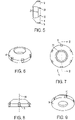
- FIGs. 5-9 are blown up drawings of the illumination system 11 shown in FIG. g1.
- FIG. 2 reveals the basics of the illumination system 11.
- the proposed illumination system 11 includes a glass disk (substrate) 18 with illumination sources 19 at its perimeter.
- Illumination sources 19 output light of different wavelengths and can be controlled individually. The different wavelengths can provide for a better contrast between the skin surface and the area (skin features) to be treated.
- Light 20 travels in the glass disk substrate 18 almost perpendicular to a system optical axis 30, thus providing oblique illumination to the skin features to be observed.
- the light output by the illumination sources 19 travels close to parallel to the skin.
- An inner aperture, of the glass disk substrate 18 is a hollow 21 as shown in this configuration.
- FIG. 7 is a view of the illumination system 11 along line B-B of the aesthetic treatment device 100 (a bottom up view).
- FIGs. 10-13 show a blown up section of an illumination system 51 according to another embodiment where illumination sources 23 are mounted on a printed circuit board 22 illuminating a transparent part 14 having reflective surfaces 52.
- the reflective surfaces 52 reflect light by 90 degrees, causing a light beam 15 to emerge almost parallel to the skin surface from the opening in the reflective surfaces 52.
- the illumination sources 23 direct light perpendicular to the skin and the reflective surfaces bend the light 90 degrees so as to be parallel to the skin.
- FIG. 13 is a view of the illumination system 5 (along C-C of the aesthetic treatment device 100 (a bottom up view).
- a device and method of an aesthetic treatment device 100 is disclosed.
- the device includes multiple focused beams to be selectively aimed at the area of the skin to be treated.
- Aspects of the present disclosure relate to a method for aesthetic treatment where multi wavelength light sources combined with an adequate imaging device is used to select the target skin area and an appropriate laser light combination is used to treat the skin area target.
- the treatment is performed by aiming focused light sources or laser beams which are powerful enough to penetrate and destroy hair follicles, treat acne and treat other dermatological disorders.
- aspects of the present invention relate to a miniature aesthetic treatment device 100 capable of performing non-contact treatment to a limited area of the skin of a person, to treating dermatological disorders such as hair follicles, acne glands, tattoo removal, wrinkles, age stains, rejuvenation and other superficial dermatological treatments.
- the imaging device 16 is capable of recognizing the area to be treated using an effective illumination device, such as the illumination system 11, illuminating the area of the skin to be treated from its periphery, thereby improving the contrast between the skin and skin surface disorders.
- Known methods use a relatively large light source with a specific wavelength range, which floods a large skin area, the light source being capable of selective treatment by photothermolysis.
- hair removal is based on the principle of selectively heating and destroying the hair follicle while avoiding significant damage to surrounding skin or tissue.
- Hair follicles are selected by photothermolysis, which is a method based on the fact that hair absorbs greater amounts of light, due to its darker color when compared with surrounding skin tissue, and a similar mechanism will work for other treatments such as skin stains and miniature overexposd veins. Hair is thus automatically selected by the light since it has a darker color and thus higher absorption coefficient.
- One of the main limitations of existing methods is the usage of the photothermolysis effect which relies on color difference between normal skin and the area to be treated, where a basic requirement is for the skin to be significantly brighter than the hair follicle or glands or and basically transparent to the used wavelength. That is the main reason that light colored (such as blonde) and white hair are almost impossible to treat using existing devices and methods since they are brighter than the surrounding skin. It is a purpose of this invention to offer a solution free of those prior art limitations.
- aspects of this disclosure relate generally to an aesthetic treatment device and method to detect the position of a small area of skin to be treated and focus a light source on the specific area without affecting, and damaging the surrounding skin area.
Landscapes
- Health & Medical Sciences (AREA)
- Life Sciences & Earth Sciences (AREA)
- Biomedical Technology (AREA)
- Engineering & Computer Science (AREA)
- Physics & Mathematics (AREA)
- Nuclear Medicine, Radiotherapy & Molecular Imaging (AREA)
- General Health & Medical Sciences (AREA)
- Veterinary Medicine (AREA)
- Public Health (AREA)
- Animal Behavior & Ethology (AREA)
- Surgery (AREA)
- Optics & Photonics (AREA)
- Radiology & Medical Imaging (AREA)
- Pathology (AREA)
- Otolaryngology (AREA)
- Molecular Biology (AREA)
- Medical Informatics (AREA)
- Heart & Thoracic Surgery (AREA)
- Electromagnetism (AREA)
- Biophysics (AREA)
- Radiation-Therapy Devices (AREA)
- Measuring And Recording Apparatus For Diagnosis (AREA)
- Measurement Of The Respiration, Hearing Ability, Form, And Blood Characteristics Of Living Organisms (AREA)
Description
- Aspects of the invention relate to a miniature device which performs aesthetic treatments such as acne treatment, wrinkle removal, hair removal, rejuvenation and other applications based on light treatment. The system may comprise a detection system which evaluates the exact area to be treated and a multiple wavelength laser or LED sources tuned to optimally treat the unwanted aesthetic disorder and aimed at a single point from different directions.
- In known aesthetic treatment devices, treatment is performed by flooding a relatively large area of skin with light without differentiation between healthy skin and the area to be treated. A typical system for dermatological treatment is described in
US Patent Publication No. 2009/0054880 A1 intended to perform dermatological treatment by intense pulses of light radiated over large skin areas. The treatment selection is performed by chromatic characteristics of the skin or hair follicles and selection between treated and not to be treated areas is performed by the light source wavelength selection in a process called photo thermolysis or wavelength depended light absorption. - Light is absorbed by dark objects, so laser energy can be absorbed by dark material in the skin, but with higher speed and intensity. This dark target matter, or chromophore, can be naturally-occurring or artificially introduced. The main drawback of this procedure is that large areas of skin are unnecessarily exposed to high levels of intense pulsed light with potential adverse results.
- For example, conventional laser hair removal systems rely on flooding large areas with high intensity light, hair removal is performed at wavelengths that will not damage the human tissue, such that the light will be transmitted by the skin to the follicle depth and destroy the follicle by photothermolysis.
- Furthermore,
WO 2005/065565 A1 discloses a handheld dermatological device for visualizing a skin treatment region prior to, during or after therapeutic treatment with therapeutic energy. Such an apparatus can include an image capture device and a display device electrically coupled to the image capture device. The apparatus can further include a head capable of transmitting therapeutic energy to a treatment area, which can be precisely aligned by the user to a desired portion of the treatment area through the use of the display device, and one or more illumination sources for illuminating a skin target region. - Since small features on the skin surface are difficult to discern due to lack of contrast, especially when the colors of feature and skin surrounding are similar, a special peripheral illumination system is disclosed which greatly improves the contrast.
- A specialized illumination technique that capitalizes on oblique illumination enhancing the image contrast is disclosed. This contrast enhancement technology is especially applicable in discerning small features with low contrast, such as blonde or white hair on top of pale skin. The illumination increases contrast by two mechanisms; oblique illumination (about 90 degrees to the optical axis of a camera) and multiple wavelength illumination from UV to infrared, each providing complimentary color to a given feature. Light passing through a glass substrate will be reflected only from non-uniform features on the skin surface, illumination from oblique angles at all azimuths is diffracted, refracted, and reflected towards the camera objective to form a bright image of the specimen superimposed onto a primarily dark background.
- A special imaging device with sensitivity matching the light sources will be used to detect and discern the areas to be treated from the surrounding areas. A second optional visible illumination light source will be used to illuminate the skin surface for positioning and image display. Selection of areas to be treated will be performed by spatial discernment rather than wavelength chromatic selection.
- The treating source will comprise a laser or an LED with an appropriate wavelength dedicated to a specific treatment application. Preferably, the light source will be a dual wavelength laser capable of performing treatment by being transmitted through the skin or by local skin penetration. The system's laser power is sufficient to produce a beam capable of penetrating the epidermis and destroying a selected target. Penetration is achieved by selecting the right wavelength to be transmitted by the skin to the target area or alternatively by increasing power density to levels that will locally perforate the epidermis and destroy targets for example, hair follicles, color pigment stains and other skin disorders such as wrinkles. A special controllable power supply will allow operation of a treatment light source under a continuous or a pulse light mode. The laser beam used in laser rejuvenation and wrinkles removal will be targeted at the wrinkle outline. It simultaneously heats the underlying skin, called the dermis. This action works to stimulate growth of new collagen fibers. As the treated area heals, the new skin that forms is smoother and firmer. As for acne, a different wavelength source will be used, usually in the 400nm region combined with a longer wavelength for heating the underlying skin.
- Acne occurs when the body begins producing an overabundance of oils and sebaceous fluids that become trapped beneath the surface due to cuticle build up or debris. When this happens, unnatural levels of bacteria can begin to form, which can trigger infections.
- Laser systems will be arranged to converge on a spot from different directions, creating a powerful spot of multi wavelength lasers on one hand and a highly diverging beam on the other hand, thereby improving the system safety. A special smart guiding mechanical system is provided for accurately selecting the area to be treated with micron accuracy.
- One feature of uniqueness of the present aesthetic treatment device is that this device achieves and sometimes overcomes the performance of the systems existing in the market for the above procedures, while integrating all the capabilities of aesthetic treatment in a miniature hand held apparatus. The treatment apparatus is based on multiple light sources, lasers or LEDs focused on the treatment area from different directions. The multiple light sources for treatment purposes could have the same wavelength or different wavelengths each optimized for a different application. Target selection is performed by a dual wavelength smart illumination system. An internal light source structure enables the aesthetic treatment device to operate with high peak intensity for the effective treatment, while the emission spectrum remains mostly in the near infra-red region. Aiming the multiple focused beams to target is performed manually or automatically.
- Due to the above features, the proposed aesthetic treatment device is potentially usable for all hair types since its working principle is based on spatial hair removal rather than selective photothermolysis.
- Another advantage of the proposed aesthetic treatment device is that the same provides an image display of the working area near and around the light sources, enabling treatment directly by a user even in concealed areas.
- In addition, the high source focus ability and miniature size enables the use of a well designed miniature treatment hand piece.
- Many disadvantages of prior art aesthetic treatment devices are advantageously solved by aspects of the present invention. A partial list is as follows:
- In prior art systems a high power light or laser is applied to a relatively large area and the required treatment is usually achieved by photothermolysis followed by collateral damage to the surrounding skin. It is an aspect of the present invention to overcome this drawback by applying a focused laser beam or light directly to the treatment location without affecting the surrounding skin.
- Some prior art treatments are performed by selective photothermolysis or by skin limited transparency to allow deep light penetration. It is another aspect of the present invention to perform treatment by spatial recognition of an area to be treated, enabling focused treatment and potential treatment, not only by photothermolysis but by a direct localized system.
- In some prior art devices, the irradiated area is discernible only by visible illumination from above with poor image contrast in some cases, yet aspects of the present invention art provide an additional peripheral illumination which improves the contrast of features on the skin surface.
- In some prior art devices, the light source is relatively large, requiring a large amount of power and complicated power electronics. It is another aspect of the present invention to provide a miniature treatment laser or LED with low power requirements, and which potentially is operated from a USB power source.
- In some prior art devices, the light source is usually a single light source per treatment handle and in the case of a laser hand piece, the light radiates in a very limited light spectrum of a few nanometers. It is another aspect of the present invention to overcome these by using a dual wavelength miniature laser or mounting several lasers or an LED at the same treatment laser head for improved efficacy.
- According to an aspect of the present invention, a miniature aesthetic treatment device discerns features to be treated on a skin surface by a peripheral illumination system based on multiple low power wavelength LED sources and is equipped with multiple high power wavelength light sources intended for therapeutic purposes directed to the features to be treated. The multiple high power wavelength light sources are preferable to a dual wavelength laser diode equipped with a focusing element. The multiple high power light sources are preferably mounted on a mechanical device serving as an optical bench and are aimed to have a point of intersection. A mechanical guidance system and an imaging device are provided to guide the focused laser energy to the treatment point of skin surface.
- There is provided in accordance with an embodiment of the present invention, an aesthetic treatment device comprising: a multi illumination system having at least one source in the visible region, disposed around a periphery of a predetermined area of skin; the illumination system comprising a disk-shaped substrate having illumination sources at its perimeter, wherein the substrate comprises an inner aperture which is a hollow, wherein the illumination system is configured to illuminate the area of the skin within the hollow; an imaging device, sensitive to the illumination system, to discern features on or in the skin within the predetermined area of skin to be treated; multiple treatment light sources mounted on an optical bench and aimed and focused to a point of treatment in the predetermined area of skin; a mechanical guidance system to guide the multiple treatment light sources; a pulse generator to control power output of the multiple treatment light sources based upon the treatment to be applied to the predetermined area of skin; wherein illumination emerging from the illumination system is primarily parallel to the skin surface.
- According to an embodiment, the multiple treatment light sources are of different wavelengths enabling different aesthetic procedures to be applied as the treatment.
- According to an embodiment, the mechanical guidance system comprises a base having at least one spherical portion and a body which is manually operable about the at least one spherical portion, to manually operate the aesthetic treatment device in near spherical movements.
- According to the disclosure, the mechanical guidance system comprises motor to move the mechanical guidance system, and the aesthetic treatment device further comprises a dedicated computerized controller to control the motor.
- According to an embodiment, the aesthetic treatment device further comprises moving focusing optical system to create different beam sizes of the light sources based upon the treatment to be applied to the predetermined area of the skin treated by the treatment light sources.
- According to the disclosure, the aesthetic treatment device further comprises a registration device to mark treated areas.
- There is provided in accordance with another embodiment of the present invention, a method for a non-therapeutic aesthetic hair or tattoo removal with a device according to the present invention, the method comprising: illuminating a predetermined skin area using multiple light sources around a periphery of the predetermined skin area, the multiple light sources having at least one source in the visible region; discerning a feature on or in the predetermined area of the skin by generating an image of the feature illuminated by the multiple light sources; and controlling power output of treatment light sources to perform the treatment on the feature.
- According to an embodiment, the controlling of the power output of the treatment light sources comprises generating different wavelengths of light between the treatment light sources based upon the treatment to be performed.
- According to an embodiment, the method further comprises moving the treatment light sources spherically about a base having at least one spherical portion.
- According to an embodiment, the method further comprises moving the treatment light sources using a motor.
- According to an embodiment, the controlling of the power output of the treatment light sources comprises generating different beam sizes between the treatment light sources.
- Additional aspects and/or advantages of the invention will be set forth in part in the description which follows and, in part, will be obvious from the description, or may be learned by practice of the invention.
-
-
FIG. 1 is schematic representation of an aesthetic treatment device according to an embodiment of the present invention; -
FIG. 2 is a blown up peripheral view of a portion of the aesthetic treatment device shown inFIG. 1 ; -
FIG. 3 is a view of the outer surface of the aesthetic treatment device shown inFIG. 1 ; -
FIG. 4 cross-sectional view of the aesthetic treatment device shown inFIG. 1 along line A-A, revealing a bottom up view of the aesthetic treatment device; -
FIGs. 5-9 are blown up views showing an illumination system according to one embodiment of the aesthetic treatment device shown inFIG. 1 ; and -
FIGs. 10-13 are blown up views showing an illumination system according to another embodiment of the aesthetic treatment device shown inFIG. 1 . - These and/or other aspects and advantages of the invention will become apparent and more readily appreciated from the following description of the embodiments, taken in conjunction with the accompanying drawings of which:
- Reference will now be made in detail to the present embodiments of the present invention, examples of which are illustrated in the accompanying drawings, wherein like reference numerals refer to the like elements throughout. The embodiments are described below in order to explain the present invention by referring to the figures.
- Aspects of the present invention disclose an aesthetic treatment device enabling application of focused light beams directly to skin disorders, including miniature ones like hair follicles, stains, wrinkle lines, tattoo particles, miniature veins, etc., by treating the disorder with minimal or no effect on the surrounding skin.
- Aspects of the present invention disclose an aesthetic treatment device enabling recognition of areas of skin to be treated. Recognition of the disorder is performed by a dual illumination system and the application of coherent or noncoherent multiple focused light sources directly to a specific recognized target for aesthetic treatments.
- Aspects of the present invention disclose a dual illumination system, such that an additional illumination system is provided in addition to a "regular" illumination system. The so called regular illumination system illuminates the skin from above and it is mounted around a camera lens. The configuration usually results in good illumination for the skin, but due to back reflections, hair and hair roots are not easily seen. The additional illumination system is mounted on a peripheral area of a system opening as shown in the relevant drawing, and provides illumination which is parallel to the skin. Features protruding out from the skin will be strongly illuminated while the skin will remain in relative darkness, creating an improved image emphasizing hair and outer surface features.
-
FIG. 1 is a schematic representation of anaesthetic treatment device 100. Animaging apparatus 16 includes acamera system 7 and a miniature imaging device 3 (seeFIGs.1 and 2 ). Thecamera system 7 is a multispectral camera system sensitive to the visible spectrum and infrared spectrum. Theminiature imaging device 3, preferably, but not necessarily, a change coupled device CCD, receives the images obtained by thecamera system 7, and provides a visual of the images obtained by thecamera system 7 for viewing by a user. Theaesthetic treatment device 100 may be connected to a computer screen, a tablet or a cell phone, or a regular screen like a television screen, wirelessly or through a USB or other connection element, or connected to an analog screen via a connector cable or other connection element. Anillumination system 11, in this instance, LEDs or miniature lamps, are disposed in the peripheral area of the skin of a person to be treated (either the user or another party). The immerging illumination is primarily parallel to the skin surface, thereby improving the contrast of different features on the skin surface. Treatment light sources, such as laser modules 40, each having alaser diode 4 and focusingoptics 8, , are mounted on a miniature optical bench 6, with eachlaser diode 4 having afocused beam 9 and aimed at the same aimingpoint 12. Eachlaser diode 4 sits in a housing such that the housing sits inside the miniature optical bench, and the miniature optical bench has the necessary electronics (e.g., an electronic chip) to drive thelaser diode 4. - The
LEDs 4 may have different wavelengths. Theaesthetic treatment device 100 is equipped with a firing button 2 which is exposed and protrudes externally from the outer surface 1 of theaesthetic treatment device 100, and a firing contact 5 connected to the firing bottom 2 by a connecting element 32. A pulse pattern of the LEDs is either predetermined in advance, such as at the factory, or may be selected by a user via software which is accessible to the user. By pushing the firing bottom 2, the firing contact 5 moves to activate as the laser modules 40, to produce the predetermined pulse pattern or pulse duration. A specialspherical bearing 13 pivotsand thus scans thefocused beams 9 across the skin surface. The user, who is performing hair removal or rejuvenation by self-activating theaesthetic treatment device 100 or performing hair removal or rejuvenation on another person, moves the upper part of the aesthetic device 100 (outer surface 1) around thespherical bearing 13 to provide a delicate laser movement at the skin surface. InFIG. 4 , line A-A shows a cross-section of theaesthetic treatment device 100 where the concentric circles represent an elastic element sealing thespherical bearing 13. Moving the outer surface 1 manually around thespherical bearing 13 will steer theLEDs 4 to different locations. Scanning of the aimingpoint 12 is provided by manually moving theaesthetic treatment device 100 around such a pivot. - The treatment lasers or
LEDs 4 are equipped with the focusingoptics 8 to adjust beam size by moving up and down of thefocused beams 9 which are directed towards the specific treatment skin area, then performing localized treatment without significant damage to the surrounding skin area. Aregistration device 54 is for registration purposes for the user to be able to mark and register the areas he/she has already treated. - An
electronics board 10 includes a control unit and a pulse generator. The control unit controls beam parameters to be applied to the skin. Control is performed through a pulse generator and performs intensity duration as required for a particular aesthetic skin treatment. The pulse generator can be operated by the user pressing the firing button 2, the user can select the power by software loaded on a computing device or can have the power displayed on a TV screen, and some separate device to control the power. -
FIGs. 5-9 are blown up drawings of theillumination system 11 shown in FIG. g1.FIG. 2 reveals the basics of theillumination system 11. The proposedillumination system 11 includes a glass disk (substrate) 18 withillumination sources 19 at its perimeter.Illumination sources 19 output light of different wavelengths and can be controlled individually. The different wavelengths can provide for a better contrast between the skin surface and the area (skin features) to be treated.Light 20 travels in theglass disk substrate 18 almost perpendicular to a systemoptical axis 30, thus providing oblique illumination to the skin features to be observed. Here, the light output by theillumination sources 19 travels close to parallel to the skin. An inner aperture, of theglass disk substrate 18 is a hollow 21 as shown in this configuration. Theillumination system 11 illuminates the area of the skin just underneath the circumference of the hollow (the area "within" the hollow) and theLEDs 4 treat the area of skin within the hollow to fix the aesthetic problem which is revealed therein.FIG. 7 is a view of theillumination system 11 along line B-B of the aesthetic treatment device 100 (a bottom up view). -
FIGs. 10-13 show a blown up section of anillumination system 51 according to another embodiment whereillumination sources 23 are mounted on a printedcircuit board 22 illuminating a transparent part 14 havingreflective surfaces 52. The reflective surfaces 52 reflect light by 90 degrees, causing alight beam 15 to emerge almost parallel to the skin surface from the opening in the reflective surfaces 52. Thus unlike inFIGs. 5-9 where theillumination sources 19 are mounted on a periphery of aglass disk substrate 18 and light is emitted nearly parallel to the skin, inFIGs. 10-13 , theillumination sources 23 direct light perpendicular to the skin and the reflective surfaces bend the light 90 degrees so as to be parallel to the skin.FIG. 13 is a view of the illumination system 5 (along C-C of the aesthetic treatment device 100 (a bottom up view). - Accordingly, a device and method of an
aesthetic treatment device 100 is disclosed. The device includes multiple focused beams to be selectively aimed at the area of the skin to be treated. Aspects of the present disclosure relate to a method for aesthetic treatment where multi wavelength light sources combined with an adequate imaging device is used to select the target skin area and an appropriate laser light combination is used to treat the skin area target. The treatment is performed by aiming focused light sources or laser beams which are powerful enough to penetrate and destroy hair follicles, treat acne and treat other dermatological disorders.More specifically, aspects of the present invention relate to a miniatureaesthetic treatment device 100 capable of performing non-contact treatment to a limited area of the skin of a person, to treating dermatological disorders such as hair follicles, acne glands, tattoo removal, wrinkles, age stains, rejuvenation and other superficial dermatological treatments. Theimaging device 16 is capable of recognizing the area to be treated using an effective illumination device, such as theillumination system 11, illuminating the area of the skin to be treated from its periphery, thereby improving the contrast between the skin and skin surface disorders. - Known methods use a relatively large light source with a specific wavelength range, which floods a large skin area, the light source being capable of selective treatment by photothermolysis. For example, hair removal is based on the principle of selectively heating and destroying the hair follicle while avoiding significant damage to surrounding skin or tissue. Hair follicles are selected by photothermolysis, which is a method based on the fact that hair absorbs greater amounts of light, due to its darker color when compared with surrounding skin tissue, and a similar mechanism will work for other treatments such as skin stains and miniature overexposd veins. Hair is thus automatically selected by the light since it has a darker color and thus higher absorption coefficient. On the other hand, hair or other skin disorders brighter than the surrounding skin area are difficult if not impossible to treat by prior art techniques. It is a purpose of the aesthetic treatment device according to an embodiment of the present invention to offer a different method based on spatial selection of hair follicles or other targets, destroying the follicle by focused light energy with little to no damage or exposure to surrounding skin or tissue.
- One of the main limitations of existing methods is the usage of the photothermolysis effect which relies on color difference between normal skin and the area to be treated, where a basic requirement is for the skin to be significantly brighter than the hair follicle or glands or and basically transparent to the used wavelength. That is the main reason that light colored (such as blonde) and white hair are almost impossible to treat using existing devices and methods since they are brighter than the surrounding skin. It is a purpose of this invention to offer a solution free of those prior art limitations.
- Aspects of this disclosure relate generally to an aesthetic treatment device and method to detect the position of a small area of skin to be treated and focus a light source on the specific area without affecting, and damaging the surrounding skin area.
- Although a few embodiments of the present invention have been shown and described, it would be appreciated by those skilled in the art that changes may be made in this embodiment without departing from the principles of the invention, the scope of which is defined in the claims.
Claims (15)
- An aesthetic treatment device (100) comprising:a multi illumination system (11) having at least one source in the visible region, to be disposed around a periphery of a predetermined area of skin, the multi illumination system comprising a disk-shaped substrate (18) having multiple illumination light sources (19, 23) at its perimeter, wherein the substrate (18) comprises an inner aperture which is a hollow (21), wherein the multi illumination system (11) is configured to illuminate the area of the skin within the hollow; wherein the substrate (18) has an optical axis (30) perpendicular to the substrate and passing through the middle of the hollow (21);an imaging device (3, 16), sensitive to the multi illumination system (11), to discern one or more features on or in the skin within the predetermined area of skin to be treated;multiple treatment light sources mounted on an optical bench aimed and focused to a point of treatment in the predetermined area of skin;a mechanical guidance system to guide the multiple treatment light sources; anda pulse generator to control power output of the multiple treatment light sources based upon the treatment to be applied to the predetermined area of skin;wherein illumination emerging from the multi illumination system (11) is perpendicular to the optical axis and primarily parallel to the skin surface.
- The aesthetic treatment device according to claim 1 wherein the mechanical guidance system comprises a base having at least one spherical portion (13) and a body which is manually operable about the at least one spherical portion (13), to manually operate the aesthetic treatment device (100) in near spherical movements.
- The aesthetic treatment device according to claim 1 or claim 2, further comprising a moving focusing optical system to create different beam sizes of the treatment light sources based upon the treatment to be applied to the predetermined area of the skin treated by the treatment light sources.
- The aesthetic treatment device according to the preceding claim, wherein controlling of the power output of the treatment light sources comprises generating different beam sizes between the treatment light sources.
- The aesthetic treatment device according to any of the preceding claims, further comprising a control unit configured for controlling the beam parameters to be applied to the skin through the pulse generator.
- The aesthetic treatment device according to any of the preceding claims, wherein controlling the power output of the treatment light sources comprises generating different wavelengths of light between the treatment light sources based upon the treatment to be performed.
- The aesthetic treatment device according to any of the preceding claims, wherein the imaging device (3, 16) is configured to generate an image of the predetermined area of the skin illuminated by the multiple illumination light sources (19, 23).
- The aesthetic treatment device according to any of the preceding claims, wherein the multiple illumination light sources (19, 23) direct respective light beams in a direction perpendicular to the optical axis of the substrate (18), through the substrate (18) and parallel to the predetermined area of skin, the predetermined area of skin being within the hollow (21) of the substrate (18).
- The aesthetic treatment device according to any of the preceding claims, wherein the disk-shaped substrate (18) comprises reflective surfaces (52), and wherein the multiple illumination light sources (23) direct respective light beams in a directional parallel to the optical axis of the substrate (18), through the substrate (18), wherein the reflective surfaces (52) reflect the light beams substantially 90 degrees so as to be parallel to the predetermined area of skin, the predetermined area of skin being within the hollow (21) of the substrate (18).
- A method for a non-therapeutic aesthetic hair or tattoo removal with a device (100) according to any of claims 1 to 9, the method comprising:illuminating a predetermined skin area using multiple illumination light sources (19, 23) around a periphery, that illuminate an inner hollow (21) which includes predetermined skin area, the multiple illumination light sources having at least one source in the visible region;discerning a feature on or in the predetermined area of the skin by generating an image of the feature illuminated by the multiple illumination light sources; andcontrolling power output of treatment light sources to perform the treatment on the feature.
- The method according to claim 10, wherein the controlling of the power output of the treatment light sources comprises generating different wavelengths of light between the treatment light sources based upon the treatment to be performed.
- The method according to any of claims 10 or 11, further comprising moving the treatment light sources spherically about a base having at least one spherical portion (13).
- The method according to any of claims 10 to 12, wherein the method further comprises moving the treatment light sources using a motor.
- The method according to any of claims 10 to 13, wherein the controlling of the power output of treatment light sources comprises generating different beam sizes between the treatment light sources.
- The method according to any of claims 10 to 12, wherein illuminating further comprises initially directing the illuminating light beams in a direction perpendicular to the predetermined area of skin and then reflecting the illuminating light beams 90 degrees to be substantially parallel to the predetermined area of skin.
Priority Applications (1)
| Application Number | Priority Date | Filing Date | Title |
|---|---|---|---|
| EP13729176.1A EP2890323B1 (en) | 2012-06-22 | 2013-05-31 | Aesthetic treatment device and method |
Applications Claiming Priority (4)
| Application Number | Priority Date | Filing Date | Title |
|---|---|---|---|
| EP12173261 | 2012-06-22 | ||
| US13/903,129 US9480529B2 (en) | 2012-06-22 | 2013-05-28 | Aesthetic treatment device and method |
| PCT/US2013/043507 WO2013191864A1 (en) | 2012-06-22 | 2013-05-31 | Aesthetic treatment device and method |
| EP13729176.1A EP2890323B1 (en) | 2012-06-22 | 2013-05-31 | Aesthetic treatment device and method |
Publications (2)
| Publication Number | Publication Date |
|---|---|
| EP2890323A1 EP2890323A1 (en) | 2015-07-08 |
| EP2890323B1 true EP2890323B1 (en) | 2022-07-20 |
Family
ID=49775037
Family Applications (1)
| Application Number | Title | Priority Date | Filing Date |
|---|---|---|---|
| EP13729176.1A Active EP2890323B1 (en) | 2012-06-22 | 2013-05-31 | Aesthetic treatment device and method |
Country Status (4)
| Country | Link |
|---|---|
| US (1) | US9480529B2 (en) |
| EP (1) | EP2890323B1 (en) |
| ES (1) | ES2928278T3 (en) |
| WO (1) | WO2013191864A1 (en) |
Families Citing this family (9)
| Publication number | Priority date | Publication date | Assignee | Title |
|---|---|---|---|---|
| US11433254B2 (en) * | 2013-03-15 | 2022-09-06 | Pavel V. Efremkin | Apparatus and method for treatment of wounds and skin medical conditions at a predetermined skin area |
| US10314763B2 (en) * | 2013-12-31 | 2019-06-11 | Teeny Clean, Llc | Eyelid care appliance |
| US10420608B2 (en) * | 2014-05-20 | 2019-09-24 | Verily Life Sciences Llc | System for laser ablation surgery |
| US10912611B2 (en) | 2016-02-01 | 2021-02-09 | S & Y Enterprises Llc | Automatic aesthetic treatment device and method |
| WO2019150359A1 (en) * | 2018-02-05 | 2019-08-08 | Shterzer Moshe | Intense pulse light (ipl) apparatus utilizing a pulse forming network (pfn) |
| US10799292B2 (en) | 2018-05-04 | 2020-10-13 | Bin Rao | High power tunable optical parametric oscillator for selective photothermolysis laser surgeries |
| US10625093B2 (en) | 2018-06-20 | 2020-04-21 | Omm Imports, Inc. | Therapeutic device providing heat and light and head assembly for same |
| CA3112985A1 (en) * | 2018-10-11 | 2020-04-16 | Lumenis Ltd | Real time monitoring of cosmetic laser aesthetic skin treatment procedures |
| JP2024501973A (en) * | 2020-12-31 | 2024-01-17 | ルミナス ビーイー リミテッド | Method and system for real-time monitoring of aesthetic skin treatment procedures with cosmetic lasers |
Citations (3)
| Publication number | Priority date | Publication date | Assignee | Title |
|---|---|---|---|---|
| US20030012461A1 (en) * | 2001-07-12 | 2003-01-16 | Moritex Corporation | Imaging apparatus and an imaging head used therefor |
| US20030026110A1 (en) * | 2001-08-06 | 2003-02-06 | Moritex Corporation | Imaging apparatus |
| EP1488737A1 (en) * | 2003-06-17 | 2004-12-22 | Moritex Corporation | Skin observing apparatus |
Family Cites Families (72)
| Publication number | Priority date | Publication date | Assignee | Title |
|---|---|---|---|---|
| US2151733A (en) | 1936-05-04 | 1939-03-28 | American Box Board Co | Container |
| DE2157990A1 (en) | 1971-11-23 | 1973-05-24 | Franz Pelz | IRRADIATION DEVICE |
| DE3245846C2 (en) | 1981-12-28 | 1986-05-28 | Mitsubishi Denki K.K., Tokio/Tokyo | Safety device for a surgical laser beam device |
| AU595580B2 (en) | 1986-06-30 | 1990-04-05 | Medical Laser Research Co., Ltd. | Semiconductor laser therapeutic apparatus |
| US5146923A (en) * | 1986-12-18 | 1992-09-15 | Dhawan Atam P | Apparatus and method for skin lesion examination |
| US4930504A (en) * | 1987-11-13 | 1990-06-05 | Diamantopoulos Costas A | Device for biostimulation of tissue and method for treatment of tissue |
| DE3832690C1 (en) * | 1988-09-26 | 1990-04-12 | Courage + Khazaka Electronic Gmbh, 5000 Koeln, De | |
| FR2665959B1 (en) * | 1990-08-16 | 1994-01-14 | Oreal | APPARATUS FOR ASSESSING THE SHINE OF A SURFACE, PARTICULARLY SKIN. |
| IL97531A (en) * | 1991-03-12 | 1995-12-31 | Kelman Elliot | Hair cutting apparatus |
| US5176130A (en) * | 1991-10-10 | 1993-01-05 | Interport International, Inc. | Infrared massage device |
| FR2709657B1 (en) | 1993-09-07 | 1995-12-01 | Deemed Int Sa | Optical designation device, in particular for microsurgery operation. |
| AT403654B (en) * | 1994-12-01 | 1998-04-27 | Binder Michael Dr | DEVICE FOR THE OPTICAL EXAMINATION OF HUMAN SKIN AND THE SAME ASSIGNMENT EVALUATION DEVICE |
| US5851181A (en) * | 1996-08-30 | 1998-12-22 | Esc Medical Systems Ltd. | Apparatus for simultaneously viewing and spectrally analyzing a portion of skin |
| JP3036232U (en) * | 1996-09-26 | 1997-04-15 | ヤーマン株式会社 | Optical hair removal device |
| US7204832B2 (en) * | 1996-12-02 | 2007-04-17 | Pálomar Medical Technologies, Inc. | Cooling system for a photo cosmetic device |
| US6162211A (en) * | 1996-12-05 | 2000-12-19 | Thermolase Corporation | Skin enhancement using laser light |
| US6081612A (en) * | 1997-02-28 | 2000-06-27 | Electro Optical Sciences Inc. | Systems and methods for the multispectral imaging and characterization of skin tissue |
| US5993440A (en) * | 1997-10-16 | 1999-11-30 | Ghassemi; Faramarz Frank | Non-invasive laser cutting device and method |
| CA2326120C (en) * | 1998-03-27 | 2015-01-13 | The General Hospital Corporation | Method and apparatus for the selective targeting of lipid-rich tissues |
| US6019482A (en) | 1998-10-15 | 2000-02-01 | Everett; Randall L. | Polychromatic body surface irradiator |
| US6595986B2 (en) * | 1998-10-15 | 2003-07-22 | Stephen Almeida | Multiple pulse photo-dermatological device |
| US6514242B1 (en) * | 1998-12-03 | 2003-02-04 | David Vasily | Method and apparatus for laser removal of hair |
| US6402739B1 (en) * | 1998-12-08 | 2002-06-11 | Y-Beam Technologies, Inc. | Energy application with cooling |
| US6210425B1 (en) * | 1999-07-08 | 2001-04-03 | Light Sciences Corporation | Combined imaging and PDT delivery system |
| US6451007B1 (en) * | 1999-07-29 | 2002-09-17 | Dale E. Koop | Thermal quenching of tissue |
| US6413267B1 (en) * | 1999-08-09 | 2002-07-02 | Theralase, Inc. | Therapeutic laser device and method including noninvasive subsurface monitoring and controlling means |
| JP3188437B2 (en) * | 1999-12-08 | 2001-07-16 | ヤーマン株式会社 | Laser irradiation probe |
| JP2002000745A (en) * | 2000-06-16 | 2002-01-08 | Nidek Co Ltd | Laser therapeutic device |
| JPWO2002060531A1 (en) * | 2001-01-29 | 2004-05-27 | ヤーマン株式会社 | Laser hair removal method and laser hair removal device |
| CN1251649C (en) * | 2001-03-30 | 2006-04-19 | 皇家菲利浦电子有限公司 | Skin treating device comprising protected radiation exit opening |
| US7217266B2 (en) * | 2001-05-30 | 2007-05-15 | Anderson R Rox | Apparatus and method for laser treatment with spectroscopic feedback |
| FR2826856B1 (en) * | 2001-07-09 | 2004-03-12 | Oreal | DEVICE FOR DETERMINING THE DEGREE OF A BODY TYPOLOGY CHARACTERISTIC |
| US20030216719A1 (en) | 2001-12-12 | 2003-11-20 | Len Debenedictis | Method and apparatus for treating skin using patterns of optical energy |
| US20040082940A1 (en) | 2002-10-22 | 2004-04-29 | Michael Black | Dermatological apparatus and method |
| CA2481112A1 (en) * | 2002-02-12 | 2003-08-21 | Science & Engineering Associates, Inc. | Cancer detection and adaptive dose optimization treatment system |
| US6702837B2 (en) | 2002-04-23 | 2004-03-09 | Phillip Gutwein | Therapeutic light device |
| US6872221B2 (en) | 2002-08-05 | 2005-03-29 | Larry Robert Lytle | Therapeutic low level laser apparatus and method |
| US7931028B2 (en) * | 2003-08-26 | 2011-04-26 | Jay Harvey H | Skin injury or damage prevention method using optical radiation |
| US20040225339A1 (en) * | 2002-12-20 | 2004-11-11 | Palomar Medical Technologies Inc. | Light treatments for acne and other disorders of follicles |
| US7006223B2 (en) * | 2003-03-07 | 2006-02-28 | 3Gen, Llc. | Dermoscopy epiluminescence device employing cross and parallel polarization |
| US20040210277A1 (en) | 2003-04-16 | 2004-10-21 | Hans Becker | Laser and light emitting diode body irradiator method and apparatus |
| US7309335B2 (en) | 2003-12-31 | 2007-12-18 | Palomar Medical Technologies, Inc. | Dermatological treatment with visualization |
| DE602005023719D1 (en) * | 2004-04-15 | 2010-11-04 | Koninkl Philips Electronics Nv | DEVICE FOR SKIN TREATMENT BY IRRADIATION |
| US20110160712A1 (en) | 2004-07-12 | 2011-06-30 | Nikolai Tankovich | Laser treatment system and method for producing thermal cavities and energy droplets |
| WO2006044652A1 (en) | 2004-10-16 | 2006-04-27 | Identix Incorporated | Diffractive imaging system for the reading and analysis of skin topology |
| WO2006092776A1 (en) | 2005-03-03 | 2006-09-08 | Leortec Ltd. | Aesthetic treatment device |
| US20060247741A1 (en) | 2005-04-28 | 2006-11-02 | Fu-Yu Hsu | Phototherapy apparatus with the function of change-over to different wavelength |
| CA2618126A1 (en) * | 2005-08-08 | 2007-02-15 | Palomar Medical Technologies, Inc. | Eye-safe photocosmetic device |
| EP1924196A2 (en) * | 2005-09-15 | 2008-05-28 | Palomar Medical Technologies, Inc. | Skin optical characterization device |
| EP1933754B1 (en) * | 2005-10-03 | 2012-11-21 | Koninklijke Philips Electronics N.V. | A hair shortening device |
| US7988688B2 (en) * | 2006-09-21 | 2011-08-02 | Lockheed Martin Corporation | Miniature apparatus and method for optical stimulation of nerves and other animal tissue |
| WO2007117580A2 (en) * | 2006-04-06 | 2007-10-18 | Palomar Medical Technologies, Inc. | Apparatus and method for skin treatment with compression and decompression |
| ES2532128T3 (en) * | 2006-06-26 | 2015-03-24 | Koninklijke Philips N.V. | Device for laser skin treatments |
| CN105342700B (en) * | 2007-04-10 | 2018-11-09 | 强度创新有限公司 | Self-contained handpiece and method for optical tissue surface treatment |
| US7951138B2 (en) * | 2007-05-23 | 2011-05-31 | Reliant Technologies, Llc | Pivoting roller tip for dermatological treatment apparatus |
| US9079022B2 (en) | 2007-09-27 | 2015-07-14 | Led Intellectual Properties, Llc | LED based phototherapy device for photo-rejuvenation of cells |
| US9474576B2 (en) | 2007-10-05 | 2016-10-25 | The Research Foundation For The State University Of New York | Coherent imaging fiber based hair removal device |
| WO2009155501A2 (en) | 2008-06-19 | 2009-12-23 | Massachusetts Institute Of Technology | Tactile sensor using elastomeric imaging |
| US8945104B2 (en) | 2008-08-22 | 2015-02-03 | Envy Medical, Inc. | Microdermabrasion system with combination skin therapies |
| BR112012001213B8 (en) * | 2009-07-23 | 2021-12-21 | Koninklijke Philips Electronics Nv | Hair clipper and method of using the hair clipper |
| JPWO2011114984A1 (en) * | 2010-03-15 | 2013-06-27 | ヤーマン株式会社 | Laser treatment equipment |
| WO2011116347A1 (en) | 2010-03-19 | 2011-09-22 | Quickvein, Inc. | Apparatus and methods for imaging blood vessels |
| DE102010029905A1 (en) | 2010-06-10 | 2011-12-15 | Carl Zeiss Smt Gmbh | Optical system of a microlithographic projection exposure apparatus |
| US20120041283A1 (en) | 2010-08-13 | 2012-02-16 | Conopco, Inc., D/B/A Unilever | Device for evaluating condition of skin or hair |
| WO2012106684A1 (en) | 2011-02-03 | 2012-08-09 | Tria Beauty, Inc. | Radiation-based dermatological devices and methods |
| US9220915B2 (en) * | 2011-02-03 | 2015-12-29 | Tria Beauty, Inc. | Devices and methods for radiation-based dermatological treatments |
| BR112013030487A2 (en) * | 2011-05-30 | 2016-09-27 | Koninkl Philips Nv | hair care device, method for detecting hair near a skin surface, and computer program product for detecting hair near a skin surface |
| WO2013068932A1 (en) * | 2011-11-10 | 2013-05-16 | Koninklijke Philips Electronics N.V. | Hair detector with multiple focal points |
| EP2656982A1 (en) * | 2012-04-27 | 2013-10-30 | Koninklijke Philips N.V. | Device for cutting hair |
| JP6293741B2 (en) * | 2012-06-04 | 2018-03-14 | コーニンクレッカ フィリップス エヌ ヴェKoninklijke Philips N.V. | LIOB-based hair cutting device |
| EP2844177B1 (en) * | 2012-07-31 | 2015-12-02 | Koninklijke Philips N.V. | Laser hair cutter |
| EP2943139B1 (en) * | 2013-01-10 | 2017-08-02 | Koninklijke Philips N.V. | A cutting head for a device for cutting hair |
-
2013
- 2013-05-28 US US13/903,129 patent/US9480529B2/en active Active
- 2013-05-31 EP EP13729176.1A patent/EP2890323B1/en active Active
- 2013-05-31 WO PCT/US2013/043507 patent/WO2013191864A1/en active Application Filing
- 2013-05-31 ES ES13729176T patent/ES2928278T3/en active Active
Patent Citations (3)
| Publication number | Priority date | Publication date | Assignee | Title |
|---|---|---|---|---|
| US20030012461A1 (en) * | 2001-07-12 | 2003-01-16 | Moritex Corporation | Imaging apparatus and an imaging head used therefor |
| US20030026110A1 (en) * | 2001-08-06 | 2003-02-06 | Moritex Corporation | Imaging apparatus |
| EP1488737A1 (en) * | 2003-06-17 | 2004-12-22 | Moritex Corporation | Skin observing apparatus |
Also Published As
| Publication number | Publication date |
|---|---|
| US20130345685A1 (en) | 2013-12-26 |
| EP2890323A1 (en) | 2015-07-08 |
| US9480529B2 (en) | 2016-11-01 |
| ES2928278T3 (en) | 2022-11-16 |
| WO2013191864A1 (en) | 2013-12-27 |
Similar Documents
| Publication | Publication Date | Title |
|---|---|---|
| US9962557B2 (en) | Aesthetic treatment device and method | |
| EP2890323B1 (en) | Aesthetic treatment device and method | |
| JP6449549B2 (en) | Beauty treatment apparatus and method | |
| US7220254B2 (en) | Dermatological treatment with visualization | |
| KR100990903B1 (en) | A method and apparatus of treating tissue | |
| US20060253176A1 (en) | Dermatological treatment device with deflector optic | |
| KR102364395B1 (en) | Method and apparatus for treating dermal melasma | |
| US20090118720A1 (en) | Dermatological Apparatus and Method | |
| US7713265B2 (en) | Apparatus and method for medically treating a tattoo | |
| US10912611B2 (en) | Automatic aesthetic treatment device and method | |
| US20230405355A1 (en) | Image guided laser therapy | |
| US20180344403A1 (en) | Hair removal device | |
| US11684419B2 (en) | Systems and methods for selective targeting of structural features in treating skin conditions | |
| JP2023505019A (en) | Devices, systems and methods for hair removal |
Legal Events
| Date | Code | Title | Description |
|---|---|---|---|
| PUAI | Public reference made under article 153(3) epc to a published international application that has entered the european phase |
Free format text: ORIGINAL CODE: 0009012 |
|
| 17P | Request for examination filed |
Effective date: 20150511 |
|
| AK | Designated contracting states |
Kind code of ref document: A1 Designated state(s): AL AT BE BG CH CY CZ DE DK EE ES FI FR GB GR HR HU IE IS IT LI LT LU LV MC MK MT NL NO PL PT RO RS SE SI SK SM TR |
|
| AX | Request for extension of the european patent |
Extension state: BA ME |
|
| DAX | Request for extension of the european patent (deleted) | ||
| STAA | Information on the status of an ep patent application or granted ep patent |
Free format text: STATUS: EXAMINATION IS IN PROGRESS |
|
| 17Q | First examination report despatched |
Effective date: 20190614 |
|
| STAA | Information on the status of an ep patent application or granted ep patent |
Free format text: STATUS: EXAMINATION IS IN PROGRESS |
|
| GRAP | Despatch of communication of intention to grant a patent |
Free format text: ORIGINAL CODE: EPIDOSNIGR1 |
|
| STAA | Information on the status of an ep patent application or granted ep patent |
Free format text: STATUS: GRANT OF PATENT IS INTENDED |
|
| INTG | Intention to grant announced |
Effective date: 20220202 |
|
| GRAS | Grant fee paid |
Free format text: ORIGINAL CODE: EPIDOSNIGR3 |
|
| GRAA | (expected) grant |
Free format text: ORIGINAL CODE: 0009210 |
|
| STAA | Information on the status of an ep patent application or granted ep patent |
Free format text: STATUS: THE PATENT HAS BEEN GRANTED |
|
| AK | Designated contracting states |
Kind code of ref document: B1 Designated state(s): AL AT BE BG CH CY CZ DE DK EE ES FI FR GB GR HR HU IE IS IT LI LT LU LV MC MK MT NL NO PL PT RO RS SE SI SK SM TR |
|
| REG | Reference to a national code |
Ref country code: GB Ref legal event code: FG4D |
|
| REG | Reference to a national code |
Ref country code: CH Ref legal event code: EP |
|
| REG | Reference to a national code |
Ref country code: DE Ref legal event code: R096 Ref document number: 602013082107 Country of ref document: DE |
|
| REG | Reference to a national code |
Ref country code: AT Ref legal event code: REF Ref document number: 1505051 Country of ref document: AT Kind code of ref document: T Effective date: 20220815 |
|
| REG | Reference to a national code |
Ref country code: IE Ref legal event code: FG4D |
|
| REG | Reference to a national code |
Ref country code: LT Ref legal event code: MG9D |
|
| REG | Reference to a national code |
Ref country code: ES Ref legal event code: FG2A Ref document number: 2928278 Country of ref document: ES Kind code of ref document: T3 Effective date: 20221116 |
|
| REG | Reference to a national code |
Ref country code: NL Ref legal event code: MP Effective date: 20220720 |
|
| PG25 | Lapsed in a contracting state [announced via postgrant information from national office to epo] |
Ref country code: SE Free format text: LAPSE BECAUSE OF FAILURE TO SUBMIT A TRANSLATION OF THE DESCRIPTION OR TO PAY THE FEE WITHIN THE PRESCRIBED TIME-LIMIT Effective date: 20220720 Ref country code: RS Free format text: LAPSE BECAUSE OF FAILURE TO SUBMIT A TRANSLATION OF THE DESCRIPTION OR TO PAY THE FEE WITHIN THE PRESCRIBED TIME-LIMIT Effective date: 20220720 Ref country code: PT Free format text: LAPSE BECAUSE OF FAILURE TO SUBMIT A TRANSLATION OF THE DESCRIPTION OR TO PAY THE FEE WITHIN THE PRESCRIBED TIME-LIMIT Effective date: 20221121 Ref country code: NO Free format text: LAPSE BECAUSE OF FAILURE TO SUBMIT A TRANSLATION OF THE DESCRIPTION OR TO PAY THE FEE WITHIN THE PRESCRIBED TIME-LIMIT Effective date: 20221020 Ref country code: NL Free format text: LAPSE BECAUSE OF FAILURE TO SUBMIT A TRANSLATION OF THE DESCRIPTION OR TO PAY THE FEE WITHIN THE PRESCRIBED TIME-LIMIT Effective date: 20220720 Ref country code: LV Free format text: LAPSE BECAUSE OF FAILURE TO SUBMIT A TRANSLATION OF THE DESCRIPTION OR TO PAY THE FEE WITHIN THE PRESCRIBED TIME-LIMIT Effective date: 20220720 Ref country code: LT Free format text: LAPSE BECAUSE OF FAILURE TO SUBMIT A TRANSLATION OF THE DESCRIPTION OR TO PAY THE FEE WITHIN THE PRESCRIBED TIME-LIMIT Effective date: 20220720 Ref country code: FI Free format text: LAPSE BECAUSE OF FAILURE TO SUBMIT A TRANSLATION OF THE DESCRIPTION OR TO PAY THE FEE WITHIN THE PRESCRIBED TIME-LIMIT Effective date: 20220720 |
|
| REG | Reference to a national code |
Ref country code: AT Ref legal event code: MK05 Ref document number: 1505051 Country of ref document: AT Kind code of ref document: T Effective date: 20220720 |
|
| PG25 | Lapsed in a contracting state [announced via postgrant information from national office to epo] |
Ref country code: PL Free format text: LAPSE BECAUSE OF FAILURE TO SUBMIT A TRANSLATION OF THE DESCRIPTION OR TO PAY THE FEE WITHIN THE PRESCRIBED TIME-LIMIT Effective date: 20220720 Ref country code: IS Free format text: LAPSE BECAUSE OF FAILURE TO SUBMIT A TRANSLATION OF THE DESCRIPTION OR TO PAY THE FEE WITHIN THE PRESCRIBED TIME-LIMIT Effective date: 20221120 Ref country code: HR Free format text: LAPSE BECAUSE OF FAILURE TO SUBMIT A TRANSLATION OF THE DESCRIPTION OR TO PAY THE FEE WITHIN THE PRESCRIBED TIME-LIMIT Effective date: 20220720 Ref country code: GR Free format text: LAPSE BECAUSE OF FAILURE TO SUBMIT A TRANSLATION OF THE DESCRIPTION OR TO PAY THE FEE WITHIN THE PRESCRIBED TIME-LIMIT Effective date: 20221021 |
|
| REG | Reference to a national code |
Ref country code: DE Ref legal event code: R097 Ref document number: 602013082107 Country of ref document: DE |
|
| PG25 | Lapsed in a contracting state [announced via postgrant information from national office to epo] |
Ref country code: SM Free format text: LAPSE BECAUSE OF FAILURE TO SUBMIT A TRANSLATION OF THE DESCRIPTION OR TO PAY THE FEE WITHIN THE PRESCRIBED TIME-LIMIT Effective date: 20220720 Ref country code: RO Free format text: LAPSE BECAUSE OF FAILURE TO SUBMIT A TRANSLATION OF THE DESCRIPTION OR TO PAY THE FEE WITHIN THE PRESCRIBED TIME-LIMIT Effective date: 20220720 Ref country code: DK Free format text: LAPSE BECAUSE OF FAILURE TO SUBMIT A TRANSLATION OF THE DESCRIPTION OR TO PAY THE FEE WITHIN THE PRESCRIBED TIME-LIMIT Effective date: 20220720 Ref country code: CZ Free format text: LAPSE BECAUSE OF FAILURE TO SUBMIT A TRANSLATION OF THE DESCRIPTION OR TO PAY THE FEE WITHIN THE PRESCRIBED TIME-LIMIT Effective date: 20220720 Ref country code: AT Free format text: LAPSE BECAUSE OF FAILURE TO SUBMIT A TRANSLATION OF THE DESCRIPTION OR TO PAY THE FEE WITHIN THE PRESCRIBED TIME-LIMIT Effective date: 20220720 |
|
| PLBE | No opposition filed within time limit |
Free format text: ORIGINAL CODE: 0009261 |
|
| STAA | Information on the status of an ep patent application or granted ep patent |
Free format text: STATUS: NO OPPOSITION FILED WITHIN TIME LIMIT |
|
| PG25 | Lapsed in a contracting state [announced via postgrant information from national office to epo] |
Ref country code: SK Free format text: LAPSE BECAUSE OF FAILURE TO SUBMIT A TRANSLATION OF THE DESCRIPTION OR TO PAY THE FEE WITHIN THE PRESCRIBED TIME-LIMIT Effective date: 20220720 Ref country code: EE Free format text: LAPSE BECAUSE OF FAILURE TO SUBMIT A TRANSLATION OF THE DESCRIPTION OR TO PAY THE FEE WITHIN THE PRESCRIBED TIME-LIMIT Effective date: 20220720 |
|
| 26N | No opposition filed |
Effective date: 20230421 |
|
| P01 | Opt-out of the competence of the unified patent court (upc) registered |
Effective date: 20230523 |
|
| PG25 | Lapsed in a contracting state [announced via postgrant information from national office to epo] |
Ref country code: AL Free format text: LAPSE BECAUSE OF FAILURE TO SUBMIT A TRANSLATION OF THE DESCRIPTION OR TO PAY THE FEE WITHIN THE PRESCRIBED TIME-LIMIT Effective date: 20220720 |
|
| PGFP | Annual fee paid to national office [announced via postgrant information from national office to epo] |
Ref country code: IT Payment date: 20230510 Year of fee payment: 11 Ref country code: FR Payment date: 20230530 Year of fee payment: 11 Ref country code: ES Payment date: 20230601 Year of fee payment: 11 Ref country code: DE Payment date: 20230530 Year of fee payment: 11 |
|
| PG25 | Lapsed in a contracting state [announced via postgrant information from national office to epo] |
Ref country code: SI Free format text: LAPSE BECAUSE OF FAILURE TO SUBMIT A TRANSLATION OF THE DESCRIPTION OR TO PAY THE FEE WITHIN THE PRESCRIBED TIME-LIMIT Effective date: 20220720 |
|
| PGFP | Annual fee paid to national office [announced via postgrant information from national office to epo] |
Ref country code: GB Payment date: 20230530 Year of fee payment: 11 |
|
| REG | Reference to a national code |
Ref country code: CH Ref legal event code: PL |
|
| PG25 | Lapsed in a contracting state [announced via postgrant information from national office to epo] |
Ref country code: MC Free format text: LAPSE BECAUSE OF FAILURE TO SUBMIT A TRANSLATION OF THE DESCRIPTION OR TO PAY THE FEE WITHIN THE PRESCRIBED TIME-LIMIT Effective date: 20220720 |
|
| REG | Reference to a national code |
Ref country code: BE Ref legal event code: MM Effective date: 20230531 |
|
| PG25 | Lapsed in a contracting state [announced via postgrant information from national office to epo] |
Ref country code: MC Free format text: LAPSE BECAUSE OF FAILURE TO SUBMIT A TRANSLATION OF THE DESCRIPTION OR TO PAY THE FEE WITHIN THE PRESCRIBED TIME-LIMIT Effective date: 20220720 Ref country code: LU Free format text: LAPSE BECAUSE OF NON-PAYMENT OF DUE FEES Effective date: 20230531 Ref country code: LI Free format text: LAPSE BECAUSE OF NON-PAYMENT OF DUE FEES Effective date: 20230531 Ref country code: CH Free format text: LAPSE BECAUSE OF NON-PAYMENT OF DUE FEES Effective date: 20230531 |
|
| REG | Reference to a national code |
Ref country code: IE Ref legal event code: MM4A |
|
| PG25 | Lapsed in a contracting state [announced via postgrant information from national office to epo] |
Ref country code: IE Free format text: LAPSE BECAUSE OF NON-PAYMENT OF DUE FEES Effective date: 20230531 |
|
| PG25 | Lapsed in a contracting state [announced via postgrant information from national office to epo] |
Ref country code: IE Free format text: LAPSE BECAUSE OF NON-PAYMENT OF DUE FEES Effective date: 20230531 |