EP2887899B1 - Improved fenestrated bone screw - Google Patents
Improved fenestrated bone screw Download PDFInfo
- Publication number
- EP2887899B1 EP2887899B1 EP13833165.7A EP13833165A EP2887899B1 EP 2887899 B1 EP2887899 B1 EP 2887899B1 EP 13833165 A EP13833165 A EP 13833165A EP 2887899 B1 EP2887899 B1 EP 2887899B1
- Authority
- EP
- European Patent Office
- Prior art keywords
- bone screw
- fenestration
- section
- screw
- shaft portion
- Prior art date
- Legal status (The legal status is an assumption and is not a legal conclusion. Google has not performed a legal analysis and makes no representation as to the accuracy of the status listed.)
- Active
Links
- 210000000988 bone and bone Anatomy 0.000 title claims description 41
- 239000000463 material Substances 0.000 claims description 12
- 230000007704 transition Effects 0.000 claims description 5
- 239000012530 fluid Substances 0.000 claims description 3
- 239000002639 bone cement Substances 0.000 description 3
- 239000007943 implant Substances 0.000 description 3
- 238000000034 method Methods 0.000 description 3
- 239000012620 biological material Substances 0.000 description 2
- 239000004568 cement Substances 0.000 description 2
- 238000005480 shot peening Methods 0.000 description 2
- 238000005482 strain hardening Methods 0.000 description 2
- 238000001356 surgical procedure Methods 0.000 description 2
- 208000010392 Bone Fractures Diseases 0.000 description 1
- 208000020084 Bone disease Diseases 0.000 description 1
- 206010017076 Fracture Diseases 0.000 description 1
- 239000013070 direct material Substances 0.000 description 1
- 230000002708 enhancing effect Effects 0.000 description 1
- 230000003116 impacting effect Effects 0.000 description 1
- 208000014674 injury Diseases 0.000 description 1
- 238000003780 insertion Methods 0.000 description 1
- 230000037431 insertion Effects 0.000 description 1
- 238000012986 modification Methods 0.000 description 1
- 230000004048 modification Effects 0.000 description 1
- 230000000399 orthopedic effect Effects 0.000 description 1
- 230000006641 stabilisation Effects 0.000 description 1
- 238000011105 stabilization Methods 0.000 description 1
- 210000000115 thoracic cavity Anatomy 0.000 description 1
- 230000008733 trauma Effects 0.000 description 1
Images


Classifications
-
- A—HUMAN NECESSITIES
- A61—MEDICAL OR VETERINARY SCIENCE; HYGIENE
- A61B—DIAGNOSIS; SURGERY; IDENTIFICATION
- A61B17/00—Surgical instruments, devices or methods, e.g. tourniquets
- A61B17/56—Surgical instruments or methods for treatment of bones or joints; Devices specially adapted therefor
- A61B17/58—Surgical instruments or methods for treatment of bones or joints; Devices specially adapted therefor for osteosynthesis, e.g. bone plates, screws, setting implements or the like
- A61B17/68—Internal fixation devices, including fasteners and spinal fixators, even if a part thereof projects from the skin
- A61B17/84—Fasteners therefor or fasteners being internal fixation devices
- A61B17/86—Pins or screws or threaded wires; nuts therefor
- A61B17/864—Pins or screws or threaded wires; nuts therefor hollow, e.g. with socket or cannulated
-
- A—HUMAN NECESSITIES
- A61—MEDICAL OR VETERINARY SCIENCE; HYGIENE
- A61B—DIAGNOSIS; SURGERY; IDENTIFICATION
- A61B17/00—Surgical instruments, devices or methods, e.g. tourniquets
- A61B17/56—Surgical instruments or methods for treatment of bones or joints; Devices specially adapted therefor
- A61B17/58—Surgical instruments or methods for treatment of bones or joints; Devices specially adapted therefor for osteosynthesis, e.g. bone plates, screws, setting implements or the like
- A61B17/68—Internal fixation devices, including fasteners and spinal fixators, even if a part thereof projects from the skin
- A61B17/84—Fasteners therefor or fasteners being internal fixation devices
- A61B17/86—Pins or screws or threaded wires; nuts therefor
- A61B17/8625—Shanks, i.e. parts contacting bone tissue
- A61B17/863—Shanks, i.e. parts contacting bone tissue with thread interrupted or changing its form along shank, other than constant taper
-
- A—HUMAN NECESSITIES
- A61—MEDICAL OR VETERINARY SCIENCE; HYGIENE
- A61B—DIAGNOSIS; SURGERY; IDENTIFICATION
- A61B17/00—Surgical instruments, devices or methods, e.g. tourniquets
- A61B17/56—Surgical instruments or methods for treatment of bones or joints; Devices specially adapted therefor
- A61B17/58—Surgical instruments or methods for treatment of bones or joints; Devices specially adapted therefor for osteosynthesis, e.g. bone plates, screws, setting implements or the like
- A61B17/68—Internal fixation devices, including fasteners and spinal fixators, even if a part thereof projects from the skin
- A61B17/84—Fasteners therefor or fasteners being internal fixation devices
- A61B17/86—Pins or screws or threaded wires; nuts therefor
- A61B17/8605—Heads, i.e. proximal ends projecting from bone
- A61B17/861—Heads, i.e. proximal ends projecting from bone specially shaped for gripping driver
- A61B17/862—Heads, i.e. proximal ends projecting from bone specially shaped for gripping driver at the periphery of the screw head
-
- A—HUMAN NECESSITIES
- A61—MEDICAL OR VETERINARY SCIENCE; HYGIENE
- A61B—DIAGNOSIS; SURGERY; IDENTIFICATION
- A61B17/00—Surgical instruments, devices or methods, e.g. tourniquets
- A61B17/56—Surgical instruments or methods for treatment of bones or joints; Devices specially adapted therefor
- A61B17/58—Surgical instruments or methods for treatment of bones or joints; Devices specially adapted therefor for osteosynthesis, e.g. bone plates, screws, setting implements or the like
- A61B17/68—Internal fixation devices, including fasteners and spinal fixators, even if a part thereof projects from the skin
- A61B17/84—Fasteners therefor or fasteners being internal fixation devices
- A61B17/86—Pins or screws or threaded wires; nuts therefor
- A61B17/8625—Shanks, i.e. parts contacting bone tissue
- A61B17/8635—Tips of screws
-
- A—HUMAN NECESSITIES
- A61—MEDICAL OR VETERINARY SCIENCE; HYGIENE
- A61B—DIAGNOSIS; SURGERY; IDENTIFICATION
- A61B17/00—Surgical instruments, devices or methods, e.g. tourniquets
- A61B17/56—Surgical instruments or methods for treatment of bones or joints; Devices specially adapted therefor
- A61B17/58—Surgical instruments or methods for treatment of bones or joints; Devices specially adapted therefor for osteosynthesis, e.g. bone plates, screws, setting implements or the like
- A61B17/68—Internal fixation devices, including fasteners and spinal fixators, even if a part thereof projects from the skin
- A61B17/84—Fasteners therefor or fasteners being internal fixation devices
- A61B17/86—Pins or screws or threaded wires; nuts therefor
- A61B17/866—Material or manufacture
-
- A—HUMAN NECESSITIES
- A61—MEDICAL OR VETERINARY SCIENCE; HYGIENE
- A61B—DIAGNOSIS; SURGERY; IDENTIFICATION
- A61B17/00—Surgical instruments, devices or methods, e.g. tourniquets
- A61B17/56—Surgical instruments or methods for treatment of bones or joints; Devices specially adapted therefor
- A61B17/58—Surgical instruments or methods for treatment of bones or joints; Devices specially adapted therefor for osteosynthesis, e.g. bone plates, screws, setting implements or the like
- A61B17/68—Internal fixation devices, including fasteners and spinal fixators, even if a part thereof projects from the skin
- A61B17/84—Fasteners therefor or fasteners being internal fixation devices
- A61B17/86—Pins or screws or threaded wires; nuts therefor
- A61B17/869—Pins or screws or threaded wires; nuts therefor characterised by an open form, e.g. wire helix
-
- A—HUMAN NECESSITIES
- A61—MEDICAL OR VETERINARY SCIENCE; HYGIENE
- A61B—DIAGNOSIS; SURGERY; IDENTIFICATION
- A61B17/00—Surgical instruments, devices or methods, e.g. tourniquets
- A61B17/56—Surgical instruments or methods for treatment of bones or joints; Devices specially adapted therefor
- A61B17/58—Surgical instruments or methods for treatment of bones or joints; Devices specially adapted therefor for osteosynthesis, e.g. bone plates, screws, setting implements or the like
- A61B17/68—Internal fixation devices, including fasteners and spinal fixators, even if a part thereof projects from the skin
- A61B17/84—Fasteners therefor or fasteners being internal fixation devices
- A61B17/86—Pins or screws or threaded wires; nuts therefor
- A61B2017/8655—Pins or screws or threaded wires; nuts therefor with special features for locking in the bone
Definitions
- the present invention is directed to bone screws as defined in the claims.
- a bone screw comprising a head portion comprising one or more slits.
- the bone screw further comprises a shaft portion connected to the head portion, the shaft portion comprising a plurality of threads and a tapered distal end.
- the shaft portion further comprises a fenestration having a first section and a second section, wherein the first section extends along a first direction and the second section extends along a second direction.
- a bone screw comprising a head portion comprising one or more slits.
- the bone screw further comprises a shaft portion connected to the head portion, wherein the shaft portion comprises a plurality of threads.
- the shaft portion further comprises a curved fenestration having at least one arc pattern along a length of the shaft portion.
- a bone screw comprising a head portion.
- the bone screw further comprises a shaft portion connected to the head portion, wherein the shaft portion comprises a plurality of threads.
- the shaft portion further comprises a fenestration having a length that extends along a majority of the length of the bone screw.
- a bone screw comprising: a head portion comprising one or more slits; and a shaft portion connected to the head portion, the shaft portion comprising a plurality of threads, the shaft portion further comprising a curved fenestration having at least one arc pattern along a length of the shaft portion.
- the curved fenestration includes at least two arc patterns formed along a length of the shaft portion.
- the shaft portion comprises dual-diameter threading.
- a bone screw comprising: a head portion; and a shaft portion connected to the head portion, the shaft portion comprising a plurality of threads, the shaft portion further comprising a fenestration having a length that extends along a majority of the length of the bone screw.
- the present application describes bone screws having improved mechanical properties.
- the bone screws described herein have unique fenestrations that can accommodate and guide different material (e.g., bone cement) through different portions of the bone screw, thereby increasing the effectiveness of the material.
- material e.g., bone cement
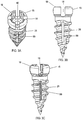
- FIGS. 1A-1C illustrate an improved fenestrated screw having an angled fenestration according to some embodiments.
- the fenestrated screw 10 includes a head portion 15 connected to a threaded shaft portion 25.
- the threaded shaft portion 25 includes an angled fenestration 60 that extends along a longitudinal axis of the fenestrated screw 10, as discussed in more detail below.
- the fenestrated screw 10 includes a head portion 15 having one or more openings or slits 18 formed therein.
- the slits 18 are configured to allow for compressibility of the head portion 15.
- the slits 18 are configured to accommodate one or more instruments, such as an insertion tool, for securely gripping the head portion 15 of the screw.
- the slits 18 are positioned symmetrically around the head portion 15 of the screw 10.
- the slits 18 need not be positioned symmetrically around the head of the screw.
- the screw 10 includes four slits 18.
- the screw can contain two, three, five or more slits.
- the head portion 15 is operably connected to a threaded shaft portion 25.
- the head portion 15 is formed monolithically with the shaft portion 25.
- the head portion 15 is formed separately and then joined with the shaft portion 25.
- the shaft portion 25 is configured to have a tapered distal end that can be inserted into a vertebral body.
- the threaded shaft portion 25 comprises a single thread, while in other embodiments, the threaded shaft portion 25 comprises a multi-diameter (e.g., dual-diameter) thread.
- the fenestrated screw 10 is cannulated such that an inner opening 42 extends from the head portion 15 to the shaft portion 25 of the screw 10.
- the inner opening 42 can be open and is in fluid contact with the fenestration 60 (discussed in more detail below). Accordingly, material that is deposited through the inner opening 42, such as bone cement, can be advantageously distributed through the fenestration 60.
- the fenestrated screw 10 includes a novel, angled fenestration 60. As shown in FIG. 1B , the fenestration 60 can extend along a longitudinal axis of the bone screw 10. In some embodiments, the fenestration 60 can extend along a majority of the length of the threaded shaft 25, thereby advantageously accommodating material along a majority of the length of the bone screw. For example, injected bone cement material, which can be used to secure the fenestrated screw 10 in bone, can now extend along a majority of the length of the bone screw 10, thereby improving the securing of the fenestrated screw in bone.
- the fenestration 60 opens to the cannulated mid-portion of the fenestrated screw, such that material that is deposited through the cannulated portion can advantageously seep into the fenestration 60, and vice versa.
- the fenestration 60 of the fenestrated screw 10 includes a first section 62 that extends along one direction and a second section 64 that extends along a different direction.
- the first section 62 of the fenestration transitions into the second section 64 via an angled corner.
- the first section 62 comprises a straight portion that extends along a longitudinal length of the threaded shaft 25, which then transitions via an angled corner into the angled second section 64.
- the angled corner of the fenestration 60 advantageously serves as a guide to direct material, such as fluids, along a certain direction along the length of the fenestration.
- the first section 62 of the fenestration 60 can transition into the second section 64 via a sharp angle.
- the angled fenestration 60 can be formed such that the first section 62 of the fenestration 60 is formed in an interior portion of the screw 10 (e.g., along the middle longitudinal axis of the screw), while the second section 64 is formed to extend from an interior portion of the screw 10 to an outer edge of the screw 10.
- the fenestration 60 effectively splits a portion of the threaded shaft 25 into two bodies.
- the fenestrated screw 10 can have an angled fenestration 60 that is formed completely in an interior portion of the screw 10 without extending to an outer edge of the screw 10. As the fenestration 60 can be made large and angled, this advantageously reduces the possibility of axial rotation and/or general screw toggling once cement or other biomaterial dries or fuses along the fenestration.
- FIGS. 2A-2C illustrate an improved fenestrated screw having a curved fenestration not falling within the scope of the claims.
- the fenestrated screw 10 in FIGS. 2A-2C comprises a head portion 15, a shaft portion 25 and a fenestration therethrough.
- the fenestration 70 does not have an edge or corner, but rather is comprised of a continuous curve.
- the fenestration 70 comprises a continuously curved opening or window formed along a portion of the shaft portion 25.
- the fenestration 70 extends along a majority of the length of the shaft portion 25, thereby allowing material to effectively seep along a majority of the length of the screw 10.
- the fenestration 70 advantageously extends from an interior portion of the screw 10 all the way to an outer edge of an exterior portion of the screw 10.
- the fenestration 70 comprises at least two arcuate portions.
- Such arcuate portions can advantageously provide a good distribution of material through the fenestrations, while properly maintaining sufficient strength in the fenestrated screw 10.
- a fenestration 70 with a single arc or more than two arcs.
- the fenestration 70 opens to and is in fluidic contact with the inner opening 42 of the screw 10.
- the fenestration 70 can be made large and curved, this advantageously reduces the possibility of axial rotation and/or general screw toggling once cement or other biomaterial dries or fuses along the fenestration.
- FIGS. 3A-3C illustrate an improved fenestrated screw having a straight, continuous fenestration not falling within the scope of the claims.
- fenestrated screw 10 includes a head 15 and a shaft 25.
- the screw 10 also includes a fenestration 80.
- the fenestration 80 comprises a substantially straight window or opening that is formed along a longitudinal length of the screw 10. While the fenestration 80 is substantially vertical and aligned along the mid-line of the screw, in other embodiments, the fenestration can be non-vertical (e.g., diagonal) and/or can be shifted away from the mid-line of the screw. In some embodiments, the fenestration 80 extends along a majority of the length of the shaft 25. Furthermore, in some embodiments, the fenestration 80 opens to and is in fluidic contact with the inner opening 42 of the screw 10.
- FIGS. 4A-4C illustrate an improved fenestrated screw having a plurality of angled, discontinuous fenestrations not falling within the scope of the claims.
- fenestrated screw 10 includes a head 15 and a shaft 25.
- the screw 10 includes a plurality of fenestrations 90.
- the fenestrations 90 are slightly angled relative to a longitudinal mid-line of the screw 10.
- the fenestrations 90 are illustrated as substantially parallel to one another, although in other embodiments, the fenestrations 90 can be at non-parallel angles relative to one another.
- fenestrations 90 there are three fenestrations 90; however, in other embodiments, there can be single, double, quadruple or more fenestrations.
- the fenestrations 90 can distributed with ease around different portions of the screw, while maintaining the integrity of the strength of the screw.
- one or more of the fenestrations 90 opens toward and is in fluidic contact with the inner hole 42 of the screw 10.
- the fenestrated screws described above can be used in a variety of medical procedures, including surgery of the spine adjacent the lumbar, thoracic and even cervical vertebrae. While it has been difficult to include screws with fenestrations in cervical vertebrae, as such screws are small in size and may have reduced strength due to fenestrations, it has been found that performing a process on the screw material, such as shot-peening or cold-working, can enhance the fatigue life and postpone the development of surface cracks that may be found. Accordingly, in some embodiments, the material of the screws described above have been shot-peened or cold-worked in order to produce small, yet strong, screws for use in the cervical region of the vertebrae. In addition, by shot-peening or cold-working the material of the screws, this can increase the strength of the screws, thereby enhancing the pull out strength of a screw without negatively impacting the strength of the overall screw.
Landscapes
- Health & Medical Sciences (AREA)
- Orthopedic Medicine & Surgery (AREA)
- Surgery (AREA)
- Life Sciences & Earth Sciences (AREA)
- Heart & Thoracic Surgery (AREA)
- Nuclear Medicine, Radiotherapy & Molecular Imaging (AREA)
- Engineering & Computer Science (AREA)
- Biomedical Technology (AREA)
- Neurology (AREA)
- Medical Informatics (AREA)
- Molecular Biology (AREA)
- Animal Behavior & Ethology (AREA)
- General Health & Medical Sciences (AREA)
- Public Health (AREA)
- Veterinary Medicine (AREA)
- Prostheses (AREA)
- Surgical Instruments (AREA)
Description
- The present invention is directed to bone screws as defined in the claims.
- Numerous procedures exist to alleviate pain caused by bone disease, trauma and fracture. During surgery, a number of implants, such as plates and stabilization systems, are used during treatment. These systems rely on bone screws that secure the implants to bone. There is thus a need to provide improved bone screws.
- Document
WO02085181 A2 - Various embodiments of orthopedic implants are provided. In some embodiments, a bone screw is provided comprising a head portion comprising one or more slits. The bone screw further comprises a shaft portion connected to the head portion, the shaft portion comprising a plurality of threads and a tapered distal end. The shaft portion further comprises a fenestration having a first section and a second section, wherein the first section extends along a first direction and the second section extends along a second direction.
- In other embodiments, a bone screw is provided comprising a head portion comprising one or more slits. The bone screw further comprises a shaft portion connected to the head portion, wherein the shaft portion comprises a plurality of threads. The shaft portion further comprises a curved fenestration having at least one arc pattern along a length of the shaft portion.
- In other embodiments, a bone screw is provided comprising a head portion. The bone screw further comprises a shaft portion connected to the head portion, wherein the shaft portion comprises a plurality of threads. The shaft portion further comprises a fenestration having a length that extends along a majority of the length of the bone screw.
In a further example not falling within the scope of the claims it is provided a bone screw comprising: a head portion comprising one or more slits; and a shaft portion connected to the head portion, the shaft portion comprising a plurality of threads, the shaft portion further comprising a curved fenestration having at least one arc pattern along a length of the shaft portion.
In a version the curved fenestration includes at least two arc patterns formed along a length of the shaft portion.
In a further version of the bone screw, the shaft portion comprises dual-diameter threading.
In a further aspect of the invention it is provided a bone screw comprising: a head portion; and a shaft portion connected to the head portion, the shaft portion comprising a plurality of threads, the shaft portion further comprising a fenestration having a length that extends along a majority of the length of the bone screw. - The invention will be more readily understood with reference to the embodiments thereof illustrated in the attached figures, in which only the embodiments of
figures 1A-1C fall within the scope of the claims: -
FIGS. 1A-1C illustrate an improved fenestrated screw having an angled fenestration according to some embodiments. -
FIGS. 2A-2C illustrate an improved fenestrated screw having a curved fenestration and not falling within the scope of the claims. -
FIGS. 3A-3C illustrate an improved fenestrated screw having a straight, continuous fenestration and not falling within the scope of the claims. -
FIGS. 4A-4C illustrate an improved fenestrated screw having parallel fenestrations and not falling within the scope of the claims. - Embodiments of the invention will now be described. The following detailed description of the invention is not intended to be illustrative of all embodiments. In describing embodiments of the present invention, specific terminology is employed for the sake of clarity. However, the invention is not intended to be limited to the specific terminology so selected. It is to be understood that each specific element includes all technical equivalents that operate in a similar manner to accomplish a similar purpose.
- The present application describes bone screws having improved mechanical properties. In particular, the bone screws described herein have unique fenestrations that can accommodate and guide different material (e.g., bone cement) through different portions of the bone screw, thereby increasing the effectiveness of the material.
-
FIGS. 1A-1C illustrate an improved fenestrated screw having an angled fenestration according to some embodiments. The fenestratedscrew 10 includes ahead portion 15 connected to a threadedshaft portion 25. The threadedshaft portion 25 includes anangled fenestration 60 that extends along a longitudinal axis of thefenestrated screw 10, as discussed in more detail below. - The
fenestrated screw 10 includes ahead portion 15 having one or more openings orslits 18 formed therein. In some embodiments, theslits 18 are configured to allow for compressibility of thehead portion 15. In addition, in other embodiments, theslits 18 are configured to accommodate one or more instruments, such as an insertion tool, for securely gripping thehead portion 15 of the screw. As shown inFIG. 1A , theslits 18 are positioned symmetrically around thehead portion 15 of thescrew 10. However, in other embodiments, theslits 18 need not be positioned symmetrically around the head of the screw. As shown inFIG. 1A , thescrew 10 includes fourslits 18. However, in other embodiments, the screw can contain two, three, five or more slits. - The
head portion 15 is operably connected to a threadedshaft portion 25. In some embodiments, thehead portion 15 is formed monolithically with theshaft portion 25. In other embodiments, thehead portion 15 is formed separately and then joined with theshaft portion 25. Theshaft portion 25 is configured to have a tapered distal end that can be inserted into a vertebral body. In some embodiments, the threadedshaft portion 25 comprises a single thread, while in other embodiments, the threadedshaft portion 25 comprises a multi-diameter (e.g., dual-diameter) thread. - As shown in the top perspective view of
FIG. 1A , thefenestrated screw 10 is cannulated such that aninner opening 42 extends from thehead portion 15 to theshaft portion 25 of thescrew 10. In some embodiments, theinner opening 42 can be open and is in fluid contact with the fenestration 60 (discussed in more detail below). Accordingly, material that is deposited through theinner opening 42, such as bone cement, can be advantageously distributed through thefenestration 60. - The
fenestrated screw 10 includes a novel, angledfenestration 60. As shown inFIG. 1B , thefenestration 60 can extend along a longitudinal axis of thebone screw 10. In some embodiments, thefenestration 60 can extend along a majority of the length of the threadedshaft 25, thereby advantageously accommodating material along a majority of the length of the bone screw. For example, injected bone cement material, which can be used to secure thefenestrated screw 10 in bone, can now extend along a majority of the length of thebone screw 10, thereby improving the securing of the fenestrated screw in bone. In some embodiments, thefenestration 60 opens to the cannulated mid-portion of the fenestrated screw, such that material that is deposited through the cannulated portion can advantageously seep into thefenestration 60, and vice versa. - As shown best in
FIGS. 1B and 1C , thefenestration 60 of thefenestrated screw 10 includes afirst section 62 that extends along one direction and asecond section 64 that extends along a different direction. In the illustrated embodiment, thefirst section 62 of the fenestration transitions into thesecond section 64 via an angled corner. As shown in the illustrated embodiments, thefirst section 62 comprises a straight portion that extends along a longitudinal length of the threadedshaft 25, which then transitions via an angled corner into the angledsecond section 64. In some embodiments, the angled corner of thefenestration 60 advantageously serves as a guide to direct material, such as fluids, along a certain direction along the length of the fenestration. In some embodiments, thefirst section 62 of thefenestration 60 can transition into thesecond section 64 via a sharp angle. - As shown in the side view of the
screw 10 inFIG. 1B , theangled fenestration 60 can be formed such that thefirst section 62 of thefenestration 60 is formed in an interior portion of the screw 10 (e.g., along the middle longitudinal axis of the screw), while thesecond section 64 is formed to extend from an interior portion of thescrew 10 to an outer edge of thescrew 10. In some embodiments, thefenestration 60 effectively splits a portion of the threadedshaft 25 into two bodies. In other embodiments not shown, thefenestrated screw 10 can have an angledfenestration 60 that is formed completely in an interior portion of thescrew 10 without extending to an outer edge of thescrew 10. As thefenestration 60 can be made large and angled, this advantageously reduces the possibility of axial rotation and/or general screw toggling once cement or other biomaterial dries or fuses along the fenestration. -
FIGS. 2A-2C illustrate an improved fenestrated screw having a curved fenestration not falling within the scope of the claims. Like the fenestrated screw discussed inFIGS. 1A-1C , thefenestrated screw 10 inFIGS. 2A-2C comprises ahead portion 15, ashaft portion 25 and a fenestration therethrough. Thefenestration 70, however, does not have an edge or corner, but rather is comprised of a continuous curve. - As shown in
FIG. 2B and 2C , thefenestration 70 comprises a continuously curved opening or window formed along a portion of theshaft portion 25. In some embodiments, thefenestration 70 extends along a majority of the length of theshaft portion 25, thereby allowing material to effectively seep along a majority of the length of thescrew 10. As shown inFIG. 2B , thefenestration 70 advantageously extends from an interior portion of thescrew 10 all the way to an outer edge of an exterior portion of thescrew 10. In addition, as shown in the illustrated embodiments, thefenestration 70 comprises at least two arcuate portions. Such arcuate portions can advantageously provide a good distribution of material through the fenestrations, while properly maintaining sufficient strength in thefenestrated screw 10. However, one skilled in the art will appreciate that it is possible to have afenestration 70 with a single arc or more than two arcs. Furthermore, in some embodiments, thefenestration 70 opens to and is in fluidic contact with theinner opening 42 of thescrew 10. As thefenestration 70 can be made large and curved, this advantageously reduces the possibility of axial rotation and/or general screw toggling once cement or other biomaterial dries or fuses along the fenestration. -
FIGS. 3A-3C illustrate an improved fenestrated screw having a straight, continuous fenestration not falling within the scope of the claims. Like the screws discussed above,fenestrated screw 10 includes ahead 15 and ashaft 25. Thescrew 10 also includes afenestration 80. However, thefenestration 80 comprises a substantially straight window or opening that is formed along a longitudinal length of thescrew 10. While thefenestration 80 is substantially vertical and aligned along the mid-line of the screw, in other embodiments, the fenestration can be non-vertical (e.g., diagonal) and/or can be shifted away from the mid-line of the screw. In some embodiments, thefenestration 80 extends along a majority of the length of theshaft 25. Furthermore, in some embodiments, thefenestration 80 opens to and is in fluidic contact with theinner opening 42 of thescrew 10. -
FIGS. 4A-4C illustrate an improved fenestrated screw having a plurality of angled, discontinuous fenestrations not falling within the scope of the claims. Like the screws discussed above,fenestrated screw 10 includes ahead 15 and ashaft 25. However, thescrew 10 includes a plurality of fenestrations 90. As shown inFIGS. 4B and 4C , the fenestrations 90 are slightly angled relative to a longitudinal mid-line of thescrew 10. In addition, the fenestrations 90 are illustrated as substantially parallel to one another, although in other embodiments, the fenestrations 90 can be at non-parallel angles relative to one another. In the illustrated embodiment, there are three fenestrations 90; however, in other embodiments, there can be single, double, quadruple or more fenestrations. Advantageously, by having multiple fenestrations 90, the fenestrations 90 can distributed with ease around different portions of the screw, while maintaining the integrity of the strength of the screw. In some embodiments, one or more of the fenestrations 90 opens toward and is in fluidic contact with theinner hole 42 of thescrew 10. - The fenestrated screws described above can be used in a variety of medical procedures, including surgery of the spine adjacent the lumbar, thoracic and even cervical vertebrae. While it has been difficult to include screws with fenestrations in cervical vertebrae, as such screws are small in size and may have reduced strength due to fenestrations, it has been found that performing a process on the screw material, such as shot-peening or cold-working, can enhance the fatigue life and postpone the development of surface cracks that may be found. Accordingly, in some embodiments, the material of the screws described above have been shot-peened or cold-worked in order to produce small, yet strong, screws for use in the cervical region of the vertebrae. In addition, by shot-peening or cold-working the material of the screws, this can increase the strength of the screws, thereby enhancing the pull out strength of a screw without negatively impacting the strength of the overall screw.
- While the invention herein disclosed has been described by means of specific embodiments and applications thereof, numerous modifications and variations can be made thereto by those skilled in the art without departing from the scope of the invention.
Claims (12)
- A bone screw (10) comprising:- a head portion (15) comprising one or more longitudinal slits (18);- a shaft portion (25) connected to the head portion (15), the shaft portion (25) comprising an outer surface having a plurality of threads and a tapered distal end, the shaft portion (25) further comprising a fenestration (60) extending along a majority of the length of the threaded shaft portion and having a first section (62) and a second section (64) extending along the outer surface, wherein the first section (62) extends along a first direction and the second section (64) extends along a second direction angled relative to the first direction, wherein the first section (62) begins at a proximal end of bone screw (10) near the head portion (15) and transitions into the second section (64) via an angled corner, wherein the first section (62) comprises a straight portion that extends along a longitudinal length of the shaft portion (25) which transitions via the angled corner into the second section (64),
wherein the one or more longitudinal slits (18) are configured to allow for compressibility of the head portion (15); and- an inner opening (42) extending from the head portion (15) to the shaft portion (25), wherein the inner opening (42) is in fluid contact with fenestration (60) to distribute material introduced in the inner opening (42) through fenestration (60). - The bone screw of claim 1, wherein the head portion (15) comprises four symmetrical slits (18).
- The bone screw of claim 1, wherein the shaft portion comprises dual-diameter threading.
- The bone screw of claim 1, wherein the first section (62) of the fenestration (60) is substantially linear and extends substantially on a midline of the bone screw (10).
- The bone screw of claim 1, the inner opening (42) is_a cannulated opening (42) that extends through the head portion (15) and the shaft portion (25).
- The bone screw of claim 1, wherein at least a portion of the bone screw is shot-peened.
- The bone screw of claim 1, wherein at least a portion of the bone screw is cold-worked.
- The bone screw of claim 1, wherein it is configured for use in a cervical region of a spine.
- The bone screw of claim 1, wherein the fenestration (60) extends along a majority of the length of the screw.
- The bone screw of claim 1, wherein one of the one or more longitudinal slits (18) is generally aligned with the first section (62) of the fenestration (60).
- The bone screw of claim 1, wherein the longitudinal slits (18) extends from an outer surface to an inner surface of the head portion (15).
- The bone screw of claim 1, wherein the first direction is parallel to a central longitudinal axis and the first section (62) extends from a first position proximate to the head portion (15) to a second position a distance along the shaft portion and the second section (64) extends along a second direction angled relative to the first direction.
Applications Claiming Priority (2)
| Application Number | Priority Date | Filing Date | Title |
|---|---|---|---|
| US13/595,181 US20140058461A1 (en) | 2012-08-27 | 2012-08-27 | Fenestrated Bone Screw |
| PCT/US2013/056807 WO2014035973A1 (en) | 2012-08-27 | 2013-08-27 | Improved fenestrated bone screw |
Publications (3)
| Publication Number | Publication Date |
|---|---|
| EP2887899A1 EP2887899A1 (en) | 2015-07-01 |
| EP2887899A4 EP2887899A4 (en) | 2016-06-22 |
| EP2887899B1 true EP2887899B1 (en) | 2017-08-02 |
Family
ID=50148689
Family Applications (1)
| Application Number | Title | Priority Date | Filing Date |
|---|---|---|---|
| EP13833165.7A Active EP2887899B1 (en) | 2012-08-27 | 2013-08-27 | Improved fenestrated bone screw |
Country Status (4)
| Country | Link |
|---|---|
| US (1) | US20140058461A1 (en) |
| EP (1) | EP2887899B1 (en) |
| JP (1) | JP2015526250A (en) |
| WO (1) | WO2014035973A1 (en) |
Cited By (13)
| Publication number | Priority date | Publication date | Assignee | Title |
|---|---|---|---|---|
| EP3831426A1 (en) | 2019-12-05 | 2021-06-09 | Heraeus Medical GmbH | Device for local application of pharmaceutical fluids |
| US11234830B2 (en) | 2019-02-14 | 2022-02-01 | Si-Bone Inc. | Implants for spinal fixation and or fusion |
| US11291485B2 (en) | 2012-05-04 | 2022-04-05 | Si-Bone Inc. | Fenestrated implant |
| US11337821B2 (en) | 2012-03-09 | 2022-05-24 | Si-Bone Inc. | Integrated implant |
| US11369419B2 (en) | 2019-02-14 | 2022-06-28 | Si-Bone Inc. | Implants for spinal fixation and or fusion |
| US11471286B2 (en) | 2012-03-09 | 2022-10-18 | Si-Bone Inc. | Systems, devices, and methods for joint fusion |
| EP4124356A1 (en) | 2021-07-28 | 2023-02-01 | Heraeus Medical GmbH | Device and method for application of a pharmaceutical fluid |
| US11571245B2 (en) | 2019-11-27 | 2023-02-07 | Si-Bone Inc. | Bone stabilizing implants and methods of placement across SI joints |
| US11633292B2 (en) | 2005-05-24 | 2023-04-25 | Si-Bone Inc. | Apparatus, systems, and methods for the fixation or fusion of bone |
| US11684378B2 (en) | 2014-09-18 | 2023-06-27 | Si-Bone Inc. | Implants for bone fixation or fusion |
| US11752011B2 (en) | 2020-12-09 | 2023-09-12 | Si-Bone Inc. | Sacro-iliac joint stabilizing implants and methods of implantation |
| US11877756B2 (en) | 2017-09-26 | 2024-01-23 | Si-Bone Inc. | Systems and methods for decorticating the sacroiliac joint |
| US11980399B2 (en) | 2013-03-15 | 2024-05-14 | Si-Bone Inc. | Implants for spinal fixation or fusion |
Families Citing this family (18)
| Publication number | Priority date | Publication date | Assignee | Title |
|---|---|---|---|---|
| US8974505B2 (en) * | 2008-06-16 | 2015-03-10 | Anna G. U. Sawa | Venting/pressure adjustment to aid in delivery of material into an anatomic region via a cannula |
| US8506608B2 (en) * | 2009-03-24 | 2013-08-13 | Douglas Cerynik | Orthopedic fixation device with bioresorbable layer |
| US20140243912A1 (en) * | 2010-05-28 | 2014-08-28 | Jean-Pierre Mobasser | Awl-tipped pedicle screw and method of implanting same |
| WO2015095126A1 (en) | 2013-12-20 | 2015-06-25 | Hartdegen Vernon | Polyaxial locking hole |
| EP3166522B1 (en) | 2014-07-10 | 2019-11-20 | Crossroads Extremity Systems, LLC | Bone implant and means of insertion |
| US11202626B2 (en) | 2014-07-10 | 2021-12-21 | Crossroads Extremity Systems, Llc | Bone implant with means for multi directional force and means of insertion |
| EP3563785B1 (en) | 2015-07-13 | 2023-11-01 | Crossroads Extremity Systems, LLC | Bone plates with dynamic elements |
| US11864753B2 (en) | 2017-02-06 | 2024-01-09 | Crossroads Extremity Systems, Llc | Implant inserter |
| EP3579762A4 (en) | 2017-02-07 | 2021-04-07 | Crossroads Extremity Systems, LLC | Counter-torque implant |
| US11147602B2 (en) | 2017-05-04 | 2021-10-19 | Warsaw Orthopedic, Inc. | Spinal implant system and method |
| US10856922B2 (en) * | 2017-06-07 | 2020-12-08 | Warsaw Orthopedic, Inc. | Spinal implant system and method |
| US11376050B2 (en) | 2017-06-27 | 2022-07-05 | Medos International Sarl | Bone screw |
| US10772667B2 (en) | 2017-12-22 | 2020-09-15 | Medos International Sarl | Bone screw with cutting tip |
| US10405889B2 (en) * | 2018-06-14 | 2019-09-10 | New Standard Device, LLC | Cold forged cutting tip for orthopedic wires and pins |
| WO2019246556A1 (en) | 2018-06-22 | 2019-12-26 | University Of Virginia Patent Foundation | Bone fixation system for promoting the union of a bone fracture and fusion of bones across a joint space and related methods thereof |
| US11903813B2 (en) | 2019-04-15 | 2024-02-20 | Kevin L. Harreld | Intraosseous screw with cortical window and system and method for associating soft tissue with bone |
| EP3808296B1 (en) | 2019-10-17 | 2021-12-22 | Heraeus Medical GmbH | Device for local application of and / or for rinsing with fluids |
| USD961081S1 (en) | 2020-11-18 | 2022-08-16 | Crossroads Extremity Systems, Llc | Orthopedic implant |
Family Cites Families (66)
| Publication number | Priority date | Publication date | Assignee | Title |
|---|---|---|---|---|
| US1091674A (en) * | 1913-09-02 | 1914-03-31 | Gramberry Sutton | Screw. |
| US1465148A (en) * | 1917-01-18 | 1923-08-14 | Rosenberg Heyman | Screw |
| US3426642A (en) * | 1962-02-05 | 1969-02-11 | Res Eng & Mfg | Self-tapping screws with threadforming projections |
| DE1475058B2 (en) * | 1965-01-30 | 1970-11-19 | Max Langensiepen Kg, 7830 Emmendingen | Expansion anchor made of thermoplastic material |
| IL46030A0 (en) * | 1974-11-11 | 1975-02-10 | Rosenberg L | Orthopaedic screw |
| DE2760081C2 (en) * | 1976-07-07 | 1986-10-16 | Arnold Kappel Schefer | Expansion anchor |
| ES239615Y (en) * | 1976-10-06 | 1979-06-16 | Upat Gmbh & Co. | EXPANDABLE PLUG BASED ON SYNTHETIC MATERIAL |
| DE3308755A1 (en) * | 1983-03-11 | 1984-09-13 | Hilti Ag, Schaan | PLASTIC SPREADING PLUG |
| US4752170A (en) * | 1986-09-04 | 1988-06-21 | Mechanical Plastics Corp. | Fastening device with nesting anchoring elements |
| IT1237496B (en) * | 1989-10-26 | 1993-06-08 | Giuseppe Vrespa | SCREW DEVICE FOR ANCHORING BONE PROSTHESES, METHOD FOR THE APPLICATION OF SUCH DEVICE AND RELATED EQUIPMENT |
| US5080543A (en) * | 1990-01-08 | 1992-01-14 | Engineered Construction Components (America) Inc. | Fastening sleeves and fastening systems employing same |
| US5145301A (en) * | 1991-02-13 | 1992-09-08 | Akio Yamamoto | Nail sustainer |
| US5161296A (en) * | 1991-07-30 | 1992-11-10 | Mechanical Plastics Corp | Method of securing an anchor with extrusion plastic molding in a solid wall substrate |
| DE4140512C1 (en) * | 1991-12-09 | 1993-04-08 | A. Raymond & Cie, Grenoble, Fr | |
| IT228979Y1 (en) * | 1992-03-09 | 1998-06-05 | Giannini Sandro | BIODEGRADABLE PROSTHESIS FOR READY FOOT CORRECTION. |
| US5752792A (en) * | 1992-09-22 | 1998-05-19 | Cobra Anchors Co. Ltd. | Anchor insert |
| SE510158C2 (en) * | 1992-10-29 | 1999-04-26 | Medevelop Ab | Anchorage elements for supporting prostheses and the use of such anchorage elements for fixing dentures |
| US5456685A (en) * | 1994-02-14 | 1995-10-10 | Smith & Nephew Dyonics, Inc. | Interference screw having a tapered back root |
| US5489210A (en) * | 1994-05-13 | 1996-02-06 | Hanosh; Frederick N. | Expanding dental implant and method for its use |
| AU696997B2 (en) * | 1994-09-15 | 1998-09-24 | Howmedica Osteonics Corp. | Conically-shaped anterior fusion cage and method of implantation |
| US5533851A (en) * | 1994-09-30 | 1996-07-09 | Clairson, Inc. | Hollow wall anchor |
| FR2753368B1 (en) * | 1996-09-13 | 1999-01-08 | Chauvin Jean Luc | EXPANSIONAL OSTEOSYNTHESIS CAGE |
| US5782866A (en) * | 1997-03-25 | 1998-07-21 | Ethicon, Inc. | System for anchoring tissue to bone |
| US5810821A (en) * | 1997-03-28 | 1998-09-22 | Biomet Inc. | Bone fixation screw system |
| US5938385A (en) * | 1998-05-22 | 1999-08-17 | Garfield; Nathaniel H. | Nested solid, solid wall anchor |
| US6186716B1 (en) * | 1998-11-12 | 2001-02-13 | Westerlund Products Corporation | Anchor bolt |
| DE59906133D1 (en) * | 1999-08-14 | 2003-07-31 | Aesculap Ag & Co Kg | BONE SCREW |
| DE60136980D1 (en) * | 2000-03-28 | 2009-01-22 | Showa Ika Kogyo Co Ltd | Spine implant, drive tool and nut guide |
| US6837658B2 (en) * | 2000-03-30 | 2005-01-04 | Fischerwerke Artur Fischer Gmbh & Co. Kg | Plug for fixing to hollow and to solid building materials |
| US6565572B2 (en) * | 2000-04-10 | 2003-05-20 | Sdgi Holdings, Inc. | Fenestrated surgical screw and method |
| US6440136B1 (en) * | 2000-05-24 | 2002-08-27 | Medtronic Ps Medical, Inc. | Apparatus for attaching to bone |
| AU2001274077A1 (en) * | 2000-05-31 | 2001-12-11 | Vese, Silvana | Device for fixing bone sections separated because of a fracture |
| US6743233B1 (en) * | 2000-08-02 | 2004-06-01 | Orthopaedic Biosystems, Ltd., Inc. | Medical screw and method of installation |
| US6648893B2 (en) * | 2000-10-27 | 2003-11-18 | Blackstone Medical, Inc. | Facet fixation devices |
| DE10055891A1 (en) * | 2000-11-10 | 2002-06-06 | Biedermann Motech Gmbh | bone screw |
| BR8100696U (en) * | 2001-04-10 | 2002-03-19 | Aziz Rassi Neto | Constructive arrangement introduced in surgical screw |
| US6494653B2 (en) * | 2001-04-17 | 2002-12-17 | Emerson Electric Company | Wall anchor |
| US6508830B2 (en) * | 2001-04-30 | 2003-01-21 | Musculoskeletal Transplant Foundation | Suture anchor |
| US20030105462A1 (en) * | 2001-11-30 | 2003-06-05 | Haider Thomas T. | Poly axial cervical plate system |
| FR2849121B1 (en) * | 2002-12-18 | 2005-08-26 | Prospection & Inventions | STRAWBERRY |
| US7048739B2 (en) * | 2002-12-31 | 2006-05-23 | Depuy Spine, Inc. | Bone plate and resilient screw system allowing bi-directional assembly |
| US7175624B2 (en) * | 2002-12-31 | 2007-02-13 | Depuy Spine, Inc. | Bone plate and screw system allowing bi-directional assembly |
| US20040254581A1 (en) * | 2003-02-04 | 2004-12-16 | Leclair Walter J. | Furcated bone screw |
| IL156033A0 (en) * | 2003-05-21 | 2004-03-28 | Ophir Fromovich Ophir Fromovic | Dental implant |
| US8062270B2 (en) * | 2003-07-15 | 2011-11-22 | Spinal Generations, Llc | Method and device for delivering medicine to bone |
| US8870836B2 (en) * | 2003-07-15 | 2014-10-28 | Spinal Generations, Llc | Method and device for delivering medicine to bone |
| US7762751B2 (en) * | 2004-02-05 | 2010-07-27 | Illinois Tool Works Inc. | Anchor |
| US7001124B2 (en) * | 2004-02-05 | 2006-02-21 | Illinois Tool Works Inc. | Anchor |
| US7824434B2 (en) * | 2004-06-07 | 2010-11-02 | Degima Gmbh | Self foreshortening fastener |
| US7935137B2 (en) * | 2004-12-08 | 2011-05-03 | Depuy Spine, Inc. | Locking bone screw and spinal plate system |
| US20060155286A1 (en) * | 2005-01-11 | 2006-07-13 | Chao-Jan Wang | Bone securing bolt |
| US7749259B2 (en) * | 2005-04-08 | 2010-07-06 | Warsaw Orthopedic, Inc. | Slotted screw for use with a vertebral member |
| US8128670B2 (en) * | 2005-04-15 | 2012-03-06 | Biodynamics Llc | Surgical expansion fasteners |
| CN2910138Y (en) * | 2006-05-18 | 2007-06-13 | 雷伟 | Universal expanding screw for pedicle of vertebral arch |
| DE102008010333A1 (en) * | 2008-02-21 | 2009-08-27 | Aesculap Ag | Magazine for receiving at least one bone screw and bone plate with such a magazine |
| ITTO20080359A1 (en) * | 2008-05-14 | 2009-11-15 | Itw Construction Products Ital | EXPANSION ANCHOR |
| US20110144703A1 (en) * | 2009-02-24 | 2011-06-16 | Krause William R | Flexible Screw |
| WO2010123859A2 (en) * | 2009-04-20 | 2010-10-28 | Osteo Innovations Llc | System and method for self filling bone screws |
| US8574273B2 (en) * | 2009-09-09 | 2013-11-05 | Innovision, Inc. | Bone screws and methods of use thereof |
| US20120029578A1 (en) * | 2010-02-05 | 2012-02-02 | Sean Suh | Bio-Resorbable Capsule Containing Fenestrated Screw System For Osteoporotic Subject |
| JP5797748B2 (en) * | 2010-05-19 | 2015-10-21 | デピュイ・シンセス・プロダクツ・インコーポレイテッド | Bone anchor |
| US8945193B2 (en) * | 2010-07-20 | 2015-02-03 | X-Spine Systems, Inc. | Minimally invasive spinal facet compression screw and system for bone joint fusion and fixation |
| US8979901B2 (en) * | 2010-08-26 | 2015-03-17 | Warsaw Orthopedic, Inc. | Dynamic bone fastener with a preset range of motion |
| USD660139S1 (en) * | 2010-09-27 | 2012-05-22 | Powers Products Iii, Llc | Anchor |
| US8771324B2 (en) * | 2011-05-27 | 2014-07-08 | Globus Medical, Inc. | Securing fasteners |
| WO2015003092A1 (en) * | 2013-07-03 | 2015-01-08 | Acumed Llc | Steerable fastener for bone |
-
2012
- 2012-08-27 US US13/595,181 patent/US20140058461A1/en not_active Abandoned
-
2013
- 2013-08-27 JP JP2015529930A patent/JP2015526250A/en active Pending
- 2013-08-27 EP EP13833165.7A patent/EP2887899B1/en active Active
- 2013-08-27 WO PCT/US2013/056807 patent/WO2014035973A1/en active Application Filing
Non-Patent Citations (1)
| Title |
|---|
| None * |
Cited By (19)
| Publication number | Priority date | Publication date | Assignee | Title |
|---|---|---|---|---|
| US11986397B2 (en) | 2005-05-24 | 2024-05-21 | Si-Bone Inc. | Apparatus, systems, and methods for the fixation or fusion of bone |
| US11633292B2 (en) | 2005-05-24 | 2023-04-25 | Si-Bone Inc. | Apparatus, systems, and methods for the fixation or fusion of bone |
| US11471286B2 (en) | 2012-03-09 | 2022-10-18 | Si-Bone Inc. | Systems, devices, and methods for joint fusion |
| US11337821B2 (en) | 2012-03-09 | 2022-05-24 | Si-Bone Inc. | Integrated implant |
| US11672664B2 (en) | 2012-03-09 | 2023-06-13 | Si-Bone Inc. | Systems, devices, and methods for joint fusion |
| US11446069B2 (en) | 2012-05-04 | 2022-09-20 | Si-Bone Inc. | Fenestrated implant |
| US11478287B2 (en) | 2012-05-04 | 2022-10-25 | Si-Bone Inc. | Fenestrated implant |
| US11291485B2 (en) | 2012-05-04 | 2022-04-05 | Si-Bone Inc. | Fenestrated implant |
| US11980399B2 (en) | 2013-03-15 | 2024-05-14 | Si-Bone Inc. | Implants for spinal fixation or fusion |
| US11684378B2 (en) | 2014-09-18 | 2023-06-27 | Si-Bone Inc. | Implants for bone fixation or fusion |
| US11877756B2 (en) | 2017-09-26 | 2024-01-23 | Si-Bone Inc. | Systems and methods for decorticating the sacroiliac joint |
| US11369419B2 (en) | 2019-02-14 | 2022-06-28 | Si-Bone Inc. | Implants for spinal fixation and or fusion |
| US11234830B2 (en) | 2019-02-14 | 2022-02-01 | Si-Bone Inc. | Implants for spinal fixation and or fusion |
| US11678997B2 (en) | 2019-02-14 | 2023-06-20 | Si-Bone Inc. | Implants for spinal fixation and or fusion |
| US11672570B2 (en) | 2019-11-27 | 2023-06-13 | Si-Bone Inc. | Bone stabilizing implants and methods of placement across SI Joints |
| US11571245B2 (en) | 2019-11-27 | 2023-02-07 | Si-Bone Inc. | Bone stabilizing implants and methods of placement across SI joints |
| EP3831426A1 (en) | 2019-12-05 | 2021-06-09 | Heraeus Medical GmbH | Device for local application of pharmaceutical fluids |
| US11752011B2 (en) | 2020-12-09 | 2023-09-12 | Si-Bone Inc. | Sacro-iliac joint stabilizing implants and methods of implantation |
| EP4124356A1 (en) | 2021-07-28 | 2023-02-01 | Heraeus Medical GmbH | Device and method for application of a pharmaceutical fluid |
Also Published As
| Publication number | Publication date |
|---|---|
| JP2015526250A (en) | 2015-09-10 |
| EP2887899A4 (en) | 2016-06-22 |
| US20140058461A1 (en) | 2014-02-27 |
| WO2014035973A1 (en) | 2014-03-06 |
| EP2887899A1 (en) | 2015-07-01 |
Similar Documents
| Publication | Publication Date | Title |
|---|---|---|
| EP2887899B1 (en) | Improved fenestrated bone screw | |
| US11871899B2 (en) | Bone plates with dynamic elements | |
| EP3000423B1 (en) | Bone plate locking mechanism | |
| US9050151B2 (en) | Bone plate and aiming block | |
| US9259255B2 (en) | Variable axis locking mechanism for use in orthopedic implants | |
| ES2427981T3 (en) | Bone fixation implant | |
| EP2085040B1 (en) | Tool for holding or guiding a receiving part for connecting a shank of a bone anchoring element to a rod | |
| CA2775735C (en) | Plating concept for distal radial fractures | |
| ES2385638T3 (en) | Bone fixation system with curved profile threads | |
| US20060217717A1 (en) | Methods and devices for stabilizing a bone anchor | |
| EP1764052A1 (en) | Bone stabilization system | |
| CA2647067A1 (en) | Bone stabilization system including multi-directional threaded fixation element | |
| JP2009142655A (en) | Anchoring device for anchoring rod in bones or vertebrae and for use with at least two rods with different diameter | |
| JP2008272485A (en) | Fixing device, set screw, use of set screw, combination of fixing device and long element, configuration having combination and holding structure, and osteosynthesis set | |
| JP2004202226A (en) | Tubular element for implant used in spinal or bone surgery | |
| KR20120084663A (en) | Triple lead bone screw | |
| EP2289440B1 (en) | Bone anchor, orthopaedic device and orthopaedic system | |
| ES2400600T3 (en) | Device for stabilizing long bone fractures | |
| AU2021106958A4 (en) | A bone fixation system and a plate therefor | |
| JP6852201B2 (en) | Lockable web plate | |
| EP3160371B1 (en) | Phalangeal head plate | |
| WO2013082576A1 (en) | Bone screw | |
| CN113473918A (en) | Orthopedic bone screw | |
| JP6553058B2 (en) | Elongated pin for external fixator application | |
| KR200383131Y1 (en) | headless cone screw thread on outside of head |
Legal Events
| Date | Code | Title | Description |
|---|---|---|---|
| PUAI | Public reference made under article 153(3) epc to a published international application that has entered the european phase |
Free format text: ORIGINAL CODE: 0009012 |
|
| 17P | Request for examination filed |
Effective date: 20150327 |
|
| AK | Designated contracting states |
Kind code of ref document: A1 Designated state(s): AL AT BE BG CH CY CZ DE DK EE ES FI FR GB GR HR HU IE IS IT LI LT LU LV MC MK MT NL NO PL PT RO RS SE SI SK SM TR |
|
| AX | Request for extension of the european patent |
Extension state: BA ME |
|
| RIN1 | Information on inventor provided before grant (corrected) |
Inventor name: BLACK, MICHAEL |
|
| DAX | Request for extension of the european patent (deleted) | ||
| RA4 | Supplementary search report drawn up and despatched (corrected) |
Effective date: 20160523 |
|
| RIC1 | Information provided on ipc code assigned before grant |
Ipc: A61B 17/86 20060101AFI20160517BHEP Ipc: A61F 2/44 20060101ALI20160517BHEP Ipc: A61B 17/70 20060101ALI20160517BHEP |
|
| GRAP | Despatch of communication of intention to grant a patent |
Free format text: ORIGINAL CODE: EPIDOSNIGR1 |
|
| INTG | Intention to grant announced |
Effective date: 20170313 |
|
| GRAS | Grant fee paid |
Free format text: ORIGINAL CODE: EPIDOSNIGR3 |
|
| GRAA | (expected) grant |
Free format text: ORIGINAL CODE: 0009210 |
|
| AK | Designated contracting states |
Kind code of ref document: B1 Designated state(s): AL AT BE BG CH CY CZ DE DK EE ES FI FR GB GR HR HU IE IS IT LI LT LU LV MC MK MT NL NO PL PT RO RS SE SI SK SM TR |
|
| REG | Reference to a national code |
Ref country code: CH Ref legal event code: EP Ref country code: AT Ref legal event code: REF Ref document number: 913585 Country of ref document: AT Kind code of ref document: T Effective date: 20170815 |
|
| REG | Reference to a national code |
Ref country code: IE Ref legal event code: FG4D |
|
| REG | Reference to a national code |
Ref country code: DE Ref legal event code: R096 Ref document number: 602013024548 Country of ref document: DE |
|
| REG | Reference to a national code |
Ref country code: NL Ref legal event code: MP Effective date: 20170802 |
|
| REG | Reference to a national code |
Ref country code: AT Ref legal event code: MK05 Ref document number: 913585 Country of ref document: AT Kind code of ref document: T Effective date: 20170802 |
|
| REG | Reference to a national code |
Ref country code: LT Ref legal event code: MG4D |
|
| PG25 | Lapsed in a contracting state [announced via postgrant information from national office to epo] |
Ref country code: LT Free format text: LAPSE BECAUSE OF FAILURE TO SUBMIT A TRANSLATION OF THE DESCRIPTION OR TO PAY THE FEE WITHIN THE PRESCRIBED TIME-LIMIT Effective date: 20170802 Ref country code: SE Free format text: LAPSE BECAUSE OF FAILURE TO SUBMIT A TRANSLATION OF THE DESCRIPTION OR TO PAY THE FEE WITHIN THE PRESCRIBED TIME-LIMIT Effective date: 20170802 Ref country code: FI Free format text: LAPSE BECAUSE OF FAILURE TO SUBMIT A TRANSLATION OF THE DESCRIPTION OR TO PAY THE FEE WITHIN THE PRESCRIBED TIME-LIMIT Effective date: 20170802 Ref country code: NO Free format text: LAPSE BECAUSE OF FAILURE TO SUBMIT A TRANSLATION OF THE DESCRIPTION OR TO PAY THE FEE WITHIN THE PRESCRIBED TIME-LIMIT Effective date: 20171102 Ref country code: HR Free format text: LAPSE BECAUSE OF FAILURE TO SUBMIT A TRANSLATION OF THE DESCRIPTION OR TO PAY THE FEE WITHIN THE PRESCRIBED TIME-LIMIT Effective date: 20170802 Ref country code: NL Free format text: LAPSE BECAUSE OF FAILURE TO SUBMIT A TRANSLATION OF THE DESCRIPTION OR TO PAY THE FEE WITHIN THE PRESCRIBED TIME-LIMIT Effective date: 20170802 Ref country code: AT Free format text: LAPSE BECAUSE OF FAILURE TO SUBMIT A TRANSLATION OF THE DESCRIPTION OR TO PAY THE FEE WITHIN THE PRESCRIBED TIME-LIMIT Effective date: 20170802 |
|
| PG25 | Lapsed in a contracting state [announced via postgrant information from national office to epo] |
Ref country code: GR Free format text: LAPSE BECAUSE OF FAILURE TO SUBMIT A TRANSLATION OF THE DESCRIPTION OR TO PAY THE FEE WITHIN THE PRESCRIBED TIME-LIMIT Effective date: 20171103 Ref country code: ES Free format text: LAPSE BECAUSE OF FAILURE TO SUBMIT A TRANSLATION OF THE DESCRIPTION OR TO PAY THE FEE WITHIN THE PRESCRIBED TIME-LIMIT Effective date: 20170802 Ref country code: IS Free format text: LAPSE BECAUSE OF FAILURE TO SUBMIT A TRANSLATION OF THE DESCRIPTION OR TO PAY THE FEE WITHIN THE PRESCRIBED TIME-LIMIT Effective date: 20171202 Ref country code: LV Free format text: LAPSE BECAUSE OF FAILURE TO SUBMIT A TRANSLATION OF THE DESCRIPTION OR TO PAY THE FEE WITHIN THE PRESCRIBED TIME-LIMIT Effective date: 20170802 Ref country code: BG Free format text: LAPSE BECAUSE OF FAILURE TO SUBMIT A TRANSLATION OF THE DESCRIPTION OR TO PAY THE FEE WITHIN THE PRESCRIBED TIME-LIMIT Effective date: 20171102 Ref country code: RS Free format text: LAPSE BECAUSE OF FAILURE TO SUBMIT A TRANSLATION OF THE DESCRIPTION OR TO PAY THE FEE WITHIN THE PRESCRIBED TIME-LIMIT Effective date: 20170802 Ref country code: PL Free format text: LAPSE BECAUSE OF FAILURE TO SUBMIT A TRANSLATION OF THE DESCRIPTION OR TO PAY THE FEE WITHIN THE PRESCRIBED TIME-LIMIT Effective date: 20170802 |
|
| REG | Reference to a national code |
Ref country code: CH Ref legal event code: PL |
|
| PG25 | Lapsed in a contracting state [announced via postgrant information from national office to epo] |
Ref country code: DK Free format text: LAPSE BECAUSE OF FAILURE TO SUBMIT A TRANSLATION OF THE DESCRIPTION OR TO PAY THE FEE WITHIN THE PRESCRIBED TIME-LIMIT Effective date: 20170802 Ref country code: CZ Free format text: LAPSE BECAUSE OF FAILURE TO SUBMIT A TRANSLATION OF THE DESCRIPTION OR TO PAY THE FEE WITHIN THE PRESCRIBED TIME-LIMIT Effective date: 20170802 Ref country code: CH Free format text: LAPSE BECAUSE OF NON-PAYMENT OF DUE FEES Effective date: 20170831 Ref country code: RO Free format text: LAPSE BECAUSE OF FAILURE TO SUBMIT A TRANSLATION OF THE DESCRIPTION OR TO PAY THE FEE WITHIN THE PRESCRIBED TIME-LIMIT Effective date: 20170802 Ref country code: LI Free format text: LAPSE BECAUSE OF NON-PAYMENT OF DUE FEES Effective date: 20170831 |
|
| REG | Reference to a national code |
Ref country code: DE Ref legal event code: R097 Ref document number: 602013024548 Country of ref document: DE |
|
| REG | Reference to a national code |
Ref country code: IE Ref legal event code: MM4A |
|
| PG25 | Lapsed in a contracting state [announced via postgrant information from national office to epo] |
Ref country code: SM Free format text: LAPSE BECAUSE OF FAILURE TO SUBMIT A TRANSLATION OF THE DESCRIPTION OR TO PAY THE FEE WITHIN THE PRESCRIBED TIME-LIMIT Effective date: 20170802 Ref country code: IT Free format text: LAPSE BECAUSE OF FAILURE TO SUBMIT A TRANSLATION OF THE DESCRIPTION OR TO PAY THE FEE WITHIN THE PRESCRIBED TIME-LIMIT Effective date: 20170802 Ref country code: MC Free format text: LAPSE BECAUSE OF FAILURE TO SUBMIT A TRANSLATION OF THE DESCRIPTION OR TO PAY THE FEE WITHIN THE PRESCRIBED TIME-LIMIT Effective date: 20170802 Ref country code: EE Free format text: LAPSE BECAUSE OF FAILURE TO SUBMIT A TRANSLATION OF THE DESCRIPTION OR TO PAY THE FEE WITHIN THE PRESCRIBED TIME-LIMIT Effective date: 20170802 Ref country code: SK Free format text: LAPSE BECAUSE OF FAILURE TO SUBMIT A TRANSLATION OF THE DESCRIPTION OR TO PAY THE FEE WITHIN THE PRESCRIBED TIME-LIMIT Effective date: 20170802 |
|
| PLBE | No opposition filed within time limit |
Free format text: ORIGINAL CODE: 0009261 |
|
| STAA | Information on the status of an ep patent application or granted ep patent |
Free format text: STATUS: NO OPPOSITION FILED WITHIN TIME LIMIT |
|
| REG | Reference to a national code |
Ref country code: BE Ref legal event code: MM Effective date: 20170831 |
|
| PG25 | Lapsed in a contracting state [announced via postgrant information from national office to epo] |
Ref country code: LU Free format text: LAPSE BECAUSE OF NON-PAYMENT OF DUE FEES Effective date: 20170827 |
|
| REG | Reference to a national code |
Ref country code: FR Ref legal event code: ST Effective date: 20180607 |
|
| 26N | No opposition filed |
Effective date: 20180503 |
|
| PG25 | Lapsed in a contracting state [announced via postgrant information from national office to epo] |
Ref country code: IE Free format text: LAPSE BECAUSE OF NON-PAYMENT OF DUE FEES Effective date: 20170827 |
|
| PG25 | Lapsed in a contracting state [announced via postgrant information from national office to epo] |
Ref country code: SI Free format text: LAPSE BECAUSE OF FAILURE TO SUBMIT A TRANSLATION OF THE DESCRIPTION OR TO PAY THE FEE WITHIN THE PRESCRIBED TIME-LIMIT Effective date: 20170802 Ref country code: FR Free format text: LAPSE BECAUSE OF NON-PAYMENT OF DUE FEES Effective date: 20171002 Ref country code: BE Free format text: LAPSE BECAUSE OF NON-PAYMENT OF DUE FEES Effective date: 20170831 |
|
| PG25 | Lapsed in a contracting state [announced via postgrant information from national office to epo] |
Ref country code: MT Free format text: LAPSE BECAUSE OF NON-PAYMENT OF DUE FEES Effective date: 20170827 |
|
| PG25 | Lapsed in a contracting state [announced via postgrant information from national office to epo] |
Ref country code: HU Free format text: LAPSE BECAUSE OF FAILURE TO SUBMIT A TRANSLATION OF THE DESCRIPTION OR TO PAY THE FEE WITHIN THE PRESCRIBED TIME-LIMIT; INVALID AB INITIO Effective date: 20130827 |
|
| PG25 | Lapsed in a contracting state [announced via postgrant information from national office to epo] |
Ref country code: CY Free format text: LAPSE BECAUSE OF FAILURE TO SUBMIT A TRANSLATION OF THE DESCRIPTION OR TO PAY THE FEE WITHIN THE PRESCRIBED TIME-LIMIT Effective date: 20170802 |
|
| PG25 | Lapsed in a contracting state [announced via postgrant information from national office to epo] |
Ref country code: MK Free format text: LAPSE BECAUSE OF FAILURE TO SUBMIT A TRANSLATION OF THE DESCRIPTION OR TO PAY THE FEE WITHIN THE PRESCRIBED TIME-LIMIT Effective date: 20170802 |
|
| PG25 | Lapsed in a contracting state [announced via postgrant information from national office to epo] |
Ref country code: TR Free format text: LAPSE BECAUSE OF FAILURE TO SUBMIT A TRANSLATION OF THE DESCRIPTION OR TO PAY THE FEE WITHIN THE PRESCRIBED TIME-LIMIT Effective date: 20170802 |
|
| PG25 | Lapsed in a contracting state [announced via postgrant information from national office to epo] |
Ref country code: PT Free format text: LAPSE BECAUSE OF FAILURE TO SUBMIT A TRANSLATION OF THE DESCRIPTION OR TO PAY THE FEE WITHIN THE PRESCRIBED TIME-LIMIT Effective date: 20170802 |
|
| PG25 | Lapsed in a contracting state [announced via postgrant information from national office to epo] |
Ref country code: AL Free format text: LAPSE BECAUSE OF FAILURE TO SUBMIT A TRANSLATION OF THE DESCRIPTION OR TO PAY THE FEE WITHIN THE PRESCRIBED TIME-LIMIT Effective date: 20170802 |
|
| PGFP | Annual fee paid to national office [announced via postgrant information from national office to epo] |
Ref country code: GB Payment date: 20230828 Year of fee payment: 11 |
|
| PGFP | Annual fee paid to national office [announced via postgrant information from national office to epo] |
Ref country code: DE Payment date: 20230829 Year of fee payment: 11 |