EP2887245A1 - A computer-implemented method for designing a biological model - Google Patents
A computer-implemented method for designing a biological model Download PDFInfo
- Publication number
- EP2887245A1 EP2887245A1 EP13306822.1A EP13306822A EP2887245A1 EP 2887245 A1 EP2887245 A1 EP 2887245A1 EP 13306822 A EP13306822 A EP 13306822A EP 2887245 A1 EP2887245 A1 EP 2887245A1
- Authority
- EP
- European Patent Office
- Prior art keywords
- computer
- group
- elements
- biological
- implemented method
- Prior art date
- Legal status (The legal status is an assumption and is not a legal conclusion. Google has not performed a legal analysis and makes no representation as to the accuracy of the status listed.)
- Ceased
Links
Images


Classifications
-
- G—PHYSICS
- G16—INFORMATION AND COMMUNICATION TECHNOLOGY [ICT] SPECIALLY ADAPTED FOR SPECIFIC APPLICATION FIELDS
- G16B—BIOINFORMATICS, i.e. INFORMATION AND COMMUNICATION TECHNOLOGY [ICT] SPECIALLY ADAPTED FOR GENETIC OR PROTEIN-RELATED DATA PROCESSING IN COMPUTATIONAL MOLECULAR BIOLOGY
- G16B5/00—ICT specially adapted for modelling or simulations in systems biology, e.g. gene-regulatory networks, protein interaction networks or metabolic networks
-
- G—PHYSICS
- G16—INFORMATION AND COMMUNICATION TECHNOLOGY [ICT] SPECIALLY ADAPTED FOR SPECIFIC APPLICATION FIELDS
- G16B—BIOINFORMATICS, i.e. INFORMATION AND COMMUNICATION TECHNOLOGY [ICT] SPECIALLY ADAPTED FOR GENETIC OR PROTEIN-RELATED DATA PROCESSING IN COMPUTATIONAL MOLECULAR BIOLOGY
- G16B45/00—ICT specially adapted for bioinformatics-related data visualisation, e.g. displaying of maps or networks
-
- Y—GENERAL TAGGING OF NEW TECHNOLOGICAL DEVELOPMENTS; GENERAL TAGGING OF CROSS-SECTIONAL TECHNOLOGIES SPANNING OVER SEVERAL SECTIONS OF THE IPC; TECHNICAL SUBJECTS COVERED BY FORMER USPC CROSS-REFERENCE ART COLLECTIONS [XRACs] AND DIGESTS
- Y02—TECHNOLOGIES OR APPLICATIONS FOR MITIGATION OR ADAPTATION AGAINST CLIMATE CHANGE
- Y02A—TECHNOLOGIES FOR ADAPTATION TO CLIMATE CHANGE
- Y02A90/00—Technologies having an indirect contribution to adaptation to climate change
- Y02A90/10—Information and communication technologies [ICT] supporting adaptation to climate change, e.g. for weather forecasting or climate simulation
Definitions
- the invention relates to the field of computers programs and systems, and more specifically to the field of merging or composing biological models.
- Biological models describe some biological phenomenon by representing molecules (or entities or elements) and interactions between them.
- Such systems aim to analyze models, to design models, or to simulate and understand the emergent properties of complex normal and pathological living systems in order to propose a global dynamic and predictive vision.
- a merging process consists in choosing which entities from input models must be grouped in the output model.
- Figures 1, 2 and 3 illustrate a composition of models A ( figure 1 ) and B ( figure 2 ) for delivering an output model AB ( figure 3 ).
- common entities are named Mp and P0.
- squares represent interactions between entities.
- the output model AB depends on which entities are supposed to be identified in both A and B models.
- Annotations are additional data attached to the model elements which add unstructured information to the model, mostly using a text format. For instance, annotations can be used to add references to public databases. Such databases are very commonly used in the bioinformatics field.
- the database provided under the trademark Uniprot is an example of a large and widely-used protein database.
- Each database has its own unique identifier syntax.
- a protein of a model could have an annotation "uniprot:P38731".
- the identifier "P38731” is Uniprot-specific and refers to an object in the Uniprot database: http://www.uniprot.org/uniprot/P38731 ("Siderophore iron transporter ARN1 ").
- these annotations are added by a user without any consistency-check, they may contain numerous errors.
- some clones or ambiguities exist in public databases.
- the merging process can either be manual or automated by algorithms, in which case the result may contain errors and, as a result, needs a manual curing.
- the present invention allows a user to go through this merging process and allows the user to correct the proposed result.
- a known advanced tool in the systems biology merging domain is the software known under the trademark SemanticSBML, which is an online tool allowing the user to select biological models either from the models database provided under the trademark BioModels repository or from the user hard drive, and to combine them.
- the aim of the operation is to produce a single output model.
- the merging user interface is presented as a table, as represented on figure 4 , each column representing a model.
- Each line represents an element of the output model. If a line is filled for only one input model, it means that an element is simply copied to the output model (for instance, ACh on the screenshot). If several columns are filled for a same line, it means that this group of input models entities will lead to a single entity or element in the output model (for instance, on the screenshot, BasalACh2 from model 1 and BasalACh2 from model 2 will be combined).
- the user can choose either to keep or to reject the group using a checkbox.
- the application also allows the user to cancel a merging group and to create a new group from preselected elements coming from input models.
- FIG. 5 An example of such an operation made with SemanticSBML is presented on figures 5 to 10 .
- the element EGF of the first model is associated with the element EGFR of the second model and element EGFR of the first model is associated with element EGF of the second model.
- eight clicks are needed (a click is represented by a dotted circle):
- a goal of the invention is to provide a computer-implemented method and a system to overcome the above mentioned problems, and particularly to drastically limit the number of drag-and-drop operations.
- Such a method allows to the user to simplify the merging of the biological models, and limit the number of operation necessary to correct the provided groups of elements.
- the present method is more productive and easy-to-use.
- the step of providing groups of elements identified as identical uses annotations attached to the biological models.
- the step of providing a set of biological models uses at least one external database.
- Accessing databases allows to use access databases with an unlimited number of biological models, and as soon as they are put in these databases.
- the method comprises the step of partially representing the biological models around a common element, with a common annotation, in case of acceptance of the corresponding merging suggestion.
- the step of moving an element from a first group to a second group in order to correct the grouping of the elements avoids an intermediate step of destruction of the first group or the second group when not empty.
- Such a method increases efficiency, and limits the time of processing by the computer.
- the step of moving an element from a first group to a second group in order to correct the grouping of the elements is performed by a drag and drop technique.
- the step of moving an element from a first group to a second group in order to correct the grouping of the elements comprises a step of creating a temporary empty group.
- the method comprises the step of activation/de-activation of a group, for example with a check box or tip box.
- elements are distinguishable by a respective representation, like a dedicated color, icon, or pattern.
- a computer-readable medium having computer-executable instructions to cause the computer system to perform the method for designing a biological model as described above.
- a computer program product stored on a computer readable medium, for designing a biological model, comprising code means for causing the system to take the steps as described above.
- an apparatus for designing a biological model comprising means for implementing the steps of the method as described above.
- each element is represented by its name and, for instance, a pattern in a little rectangle with a specific fill which indicates the origin model of the element.
- Figure 11 represents one merging group.
- a merging group also contains a checkbox. The user can check it if he wants to consider the merging proposal or uncheck it if he wants to ignore it.
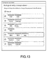
- an initial list with as many merging groups as the total number of elements is displayed to the user, each group containing one model element, as for example illustrated on figure 12 . If a merging algorithm is provided, the initialization of the list comes from the algorithm result, as for example illustrated on figure 13 .
- Figures 14 , 15 and 16 illustrate a random step in the merging process. In the present example, seven merging groups are initially represented.
- the user can change the current state of merging groups with a full expressivity using a single atomic interaction. This interaction can be implemented by a drag and drop.
- the user drags the element “sag” element from the fifth merging group and drops it to the fourth one.
- element "sag” is then identified with element "SAG" of the fourth merging group.
- a particular case of the method is the creation of a new merging group.
- the user removes GSK3B from the last merging group.
- a contextual view is provided, based on the selected merging group.
- This contextual view consists of a graph with all the elements (Frizzled) of the merging group represented a single node, completed by the two-level neighborhood (Wnt, Complex Wnt-Frzzl) of the element in each origin model.
- the same legend as above is used to indicate the origin model of each represented node.
- a specific legend is used for the "merging group node" (here, a checked pattern).
- element Frizzled is selected from the wave model, its neighbors (Wnt, Complex Wnt-Frzzl) are represented on the right.
- “re38” represents the interaction between Frizzled, Wnt and Complex Wnt-Frzzl: the reaction between a Wnt and a Frizzled gives a "Complex Wnt-Frzzl”.
- element Frzzl is selected from the striped model, its neighbors (Wnt, Complex_br_(Wnt/Frizzled) are represented on the right. "r1" represents the interaction between Frzzl, Wnt and the complex.
- Figure 26 illustrates the steps of the computer-implemented method according to an aspect of the invention for designing a biological model comprising the steps of:
- Figure 27 illustrates a computer network or similar digital processing environment in which the present invention may be implemented.
- Client computer(s)/devices CL and server computer(s) SV provide processing, storage, and input/output devices executing application programs and the like.
- Client computer(s)/devices CL can also be linked through communications network CNET to other computing devices, including other client devices/processes CL and server computer(s) SV.
- Communications network 70 can be part of a remote access network, a global network (e.g., the Internet), a worldwide collection of computers, Local area or Wide area networks, and gateways that currently use respective protocols (TCP/IP, Bluetooth, etc.) to communicate with one another.
- Other electronic device/computer network architectures are suitable.
- FIG 28 is a diagram of the internal structure of a computer (e.g., client processor/device CL or server computers SV) in the computer system of figure 26 .
- Each computer CL, SV contains system bus SB, where a bus is a set of hardware lines used for data transfer among the components of a computer or processing system.
- Bus SB is essentially a shared conduit that connects different elements of a computer system (e.g., processor, disk storage, memory, input/output ports, network ports, etc...) that enables the transfer of information between the elements.
- I/O device interface DI for connecting various input and output devices (e.g., keyboard, mouse, displays, printers, speakers, etc.) to the computer CL, SV.
- Network interface NI allows the computer to connect to various other devices attached to a network (e.g., network CNET of figure 27 ).
- Memory MEM provides volatile storage for computer software instructions SI and data CPP used to implement an embodiment of the present invention (e.g., a first path builder PB, means CM for computing a second path, an updater UD implementing the method discussed in Figs 1 to 26 , and supporting code detailed above).
- SI and data CPP used to implement an embodiment of the present invention (e.g., a first path builder PB, means CM for computing a second path, an updater UD implementing the method discussed in Figs 1 to 26 , and supporting code detailed above).
- Disk storage DS provides non-volatile storage for computer software instructions SI and data DAT used to implement an embodiment of the present invention.
- Central processor unit CPU is also attached to system bus SB and provides for the execution of computer instructions.
- the processor routines SI and data DAT are a computer program product (generally referenced CPP), including a computer readable medium (e.g., a removable storage medium such as one or more DVD-ROM's, CD-ROM's, diskettes, tapes, etc%) that provides at least a portion of the software instructions for the invention system.
- Computer program product CPP can be installed by any suitable software installation procedure, as is well known in the art.
- the software instructions may also be downloaded over a cable, communication and/or wireless connection.
- the invention programs are a computer program propagated signal product SP embodied on a propagated signal on a propagation medium (e.g., a radio wave, an infrared wave, a laser wave, a sound wave, or an electrical wave propagated over a global network such as the Internet, or other network(s)).
- a propagation medium e.g., a radio wave, an infrared wave, a laser wave, a sound wave, or an electrical wave propagated over a global network such as the Internet, or other network(s).
- Such carrier medium or signals provide at least a portion of the software instructions for the present invention routines/program CPP.
- the propagated signal is an analog carrier wave or digital signal carried on the propagated medium.
- the propagated signal may be a digitized signal propagated over a global network (e.g., the Internet), a telecommunications network, or other network.
- the propagated signal is a signal that is transmitted over the propagation medium over a period of time, such as the instructions for a software application sent in packets over a network over a period of milliseconds, seconds, minutes, or longer.
- the computer readable medium of computer program product CPP is a propagation medium that the computer system CL may receive and read, such as by receiving the propagation medium and identifying a propagated signal embodied in the propagation medium, as described above for computer program propagated signal product.
- carrier medium or transient carrier encompasses the foregoing transient signals, propagated signals, propagated medium, storage medium and the like.
Abstract
- providing (1) a set of biological models, each biological model comprising a plurality of elements and interactions between elements;
- providing (2) groups of elements identified as identical, each element having an associated biological model;
- moving (3) an element from a first group to a second group in order to correct the grouping of the elements;
- updating (4) both groups; and
- creating (5) a combined model by combining the set of biological models according to the updated groups.
Description
- The invention relates to the field of computers programs and systems, and more specifically to the field of merging or composing biological models. Biological models describe some biological phenomenon by representing molecules (or entities or elements) and interactions between them.
- Such systems aim to analyze models, to design models, or to simulate and understand the emergent properties of complex normal and pathological living systems in order to propose a global dynamic and predictive vision.
- A merging process consists in choosing which entities from input models must be grouped in the output model.
-
Figures 1, 2 and 3 illustrate a composition of models A (figure 1 ) and B (figure 2 ) for delivering an output model AB (figure 3 ). On this example, common entities are named Mp and P0. On these figures, squares represent interactions between entities. The output model AB depends on which entities are supposed to be identified in both A and B models. - This series of choices is a non-trivial process, for various reasons (a same biological phenomenon may have different modeling, models may have been made by different people, with different naming conventions, ...). Many criterions can be used to help making these choices, as molecules names, annotations or graph topology.
- Annotations are additional data attached to the model elements which add unstructured information to the model, mostly using a text format. For instance, annotations can be used to add references to public databases. Such databases are very commonly used in the bioinformatics field.
- The database provided under the trademark Uniprot is an example of a large and widely-used protein database. Each database has its own unique identifier syntax. For instance, a protein of a model could have an annotation "uniprot:P38731". The identifier "P38731" is Uniprot-specific and refers to an object in the Uniprot database: http://www.uniprot.org/uniprot/P38731 ("Siderophore iron transporter ARN1 "). As these annotations are added by a user without any consistency-check, they may contain numerous errors. Moreover, some clones or ambiguities exist in public databases. These two points explain why even with fully-annotated models, merging is not a straightforward process.
- The merging process can either be manual or automated by algorithms, in which case the result may contain errors and, as a result, needs a manual curing.
- The present invention allows a user to go through this merging process and allows the user to correct the proposed result.
- A known advanced tool in the systems biology merging domain is the software known under the trademark SemanticSBML, which is an online tool allowing the user to select biological models either from the models database provided under the trademark BioModels repository or from the user hard drive, and to combine them. The aim of the operation is to produce a single output model.
- The merging user interface is presented as a table, as represented on
figure 4 , each column representing a model. Each line represents an element of the output model. If a line is filled for only one input model, it means that an element is simply copied to the output model (for instance, ACh on the screenshot). If several columns are filled for a same line, it means that this group of input models entities will lead to a single entity or element in the output model (for instance, on the screenshot, BasalACh2 frommodel 1 and BasalACh2 frommodel 2 will be combined). - For each line, the user can choose either to keep or to reject the group using a checkbox. The application also allows the user to cancel a merging group and to create a new group from preselected elements coming from input models.
- With the state of the art solution, it is not possible to change an element from a merging group to another one without implying numerous interactions from the user, corresponding to numerous steps of the implemented method. For instance, if an element A needs to be added to a pre-existing merging group {B, C, D}, the user must:
- explode the group {B, C, D},
- select A, then B, then C, then D, and
- click on the "match selected" command.
- The needed number of interactions to do a simple operation is a major drawback for the usability and the productivity of the application.
- An example of such an operation made with SemanticSBML is presented on
figures 5 to 10 . Onfigure 5 , the element EGF of the first model is associated with the element EGFR of the second model and element EGFR of the first model is associated with element EGF of the second model. To correct the mistake, eight clicks are needed (a click is represented by a dotted circle): - one click to explode the first group "EGF / EGFR";
- one click to explode the second group "EGFR / EGF";
- two clicks to select EGF from each model, then one click to create a new group with them ("match selected");
- two clicks to select EGFR from each model; and
- one click to create a new group with them ("match selected").
- A goal of the invention is to provide a computer-implemented method and a system to overcome the above mentioned problems, and particularly to drastically limit the number of drag-and-drop operations.
- It is proposed, according to one aspect of the invention, a computer-implemented method for designing a biological model comprising the steps of:
- providing a set of biological models, each biological model comprising a plurality of elements and interactions between elements;
- providing groups of elements identified as identical, each element having an associated biological model;
- moving an element from a first group to a second group in order to correct the grouping of the elements;
- updating both groups; and
- creating a combined model by combining the set of biological models according to the updated groups.
- Such a method allows to the user to simplify the merging of the biological models, and limit the number of operation necessary to correct the provided groups of elements. The present method is more productive and easy-to-use.
- Such a single moving interaction, in addition to the existence of a specific "non-grouped elements" group and of available empty groups, gives the ability to the user to express the whole set of merging combinations while limiting the number of user interactions.
- According to an embodiment, the step of providing groups of elements identified as identical uses annotations attached to the biological models.
- The use of annotations gives identifications clues to process a list of merging suggestions.
- According to an embodiment, the step of providing a set of biological models uses at least one external database.
- Accessing databases allows to use access databases with an unlimited number of biological models, and as soon as they are put in these databases.
- According to an embodiment, the method comprises the step of partially representing the biological models around a common element, with a common annotation, in case of acceptance of the corresponding merging suggestion.
- It is then possible to visualize the portion of the combined model corresponding to the element that the user is currently processing and understand the result of a merging for the neighborhoods of the element.
- According to an embodiment, the step of moving an element from a first group to a second group in order to correct the grouping of the elements avoids an intermediate step of destruction of the first group or the second group when not empty.
- Such a method increases efficiency, and limits the time of processing by the computer.
- According to an embodiment, the step of moving an element from a first group to a second group in order to correct the grouping of the elements is performed by a drag and drop technique.
- Thus, it is an easy way to perform this step.
- According to an embodiment, the step of moving an element from a first group to a second group in order to correct the grouping of the elements comprises a step of creating a temporary empty group.
- Thus, it is an easy way to perform the creation of a new group, using the same kind of user interaction.
- According to an embodiment, the method comprises the step of activation/de-activation of a group, for example with a check box or tip box.
- According to an embodiment, in a group, elements are distinguishable by a respective representation, like a dedicated color, icon, or pattern.
- It is proposed, according to another aspect of the invention, a computer-readable medium having computer-executable instructions to cause the computer system to perform the method for designing a biological model as described above.
- It is proposed, according to another aspect of the invention, a computer program product, stored on a computer readable medium, for designing a biological model, comprising code means for causing the system to take the steps as described above.
- It is proposed, according to another aspect of the invention, an apparatus for designing a biological model comprising means for implementing the steps of the method as described above.
- The invention will be better understood with the study of some embodiments described by way of non-limiting examples and illustrated by the accompanying drawings wherein :
-
figures 1 to 10 illustrate state of the art for combining or merging biological models; -
figures 11 to 26 illustrate an example of computer-implemented method for designing a biological model, according to an aspect of the invention; -
figure 27 illustrates a computer network or similar digital processing environment in which the present invention may be implemented; and -
figure 28 illustrates a diagram of the internal structure of a computer. - Following figures explain more in details the functioning of the present invention.
- After a selection of biological models by the user to compose a combined model, elements from these models are displayed using a partial view. On
figure 11 , each element is represented by its name and, for instance, a pattern in a little rectangle with a specific fill which indicates the origin model of the element. - If different model elements are displayed as grouped, it means that they are likely to be merged together. Such a group is named a "merging group".
Figure 11 represents one merging group. - A merging group also contains a checkbox. The user can check it if he wants to consider the merging proposal or uncheck it if he wants to ignore it.
- If the merging process is only manual, an initial list with as many merging groups as the total number of elements is displayed to the user, each group containing one model element, as for example illustrated on
figure 12 . If a merging algorithm is provided, the initialization of the list comes from the algorithm result, as for example illustrated onfigure 13 . - The specific character of the present method concerns the way to modify the merging proposal list.
Figures 14 ,15 and16 illustrate a random step in the merging process. In the present example, seven merging groups are initially represented. - The user can change the current state of merging groups with a full expressivity using a single atomic interaction. This interaction can be implemented by a drag and drop.
- In the example, the user drags the element "sag" element from the fifth merging group and drops it to the fourth one. As a result, element "sag" is then identified with element "SAG" of the fourth merging group.
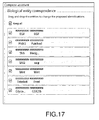
- A particular case of the method is the creation of a new merging group. In the example illustrated on
figures 17 ,18 and19 , the user removes GSK3B from the last merging group. - In order to help the user in the merging process, a contextual view is provided, based on the selected merging group. This contextual view consists of a graph with all the elements (Frizzled) of the merging group represented a single node, completed by the two-level neighborhood (Wnt, Complex Wnt-Frzzl) of the element in each origin model. The same legend as above is used to indicate the origin model of each represented node. A specific legend is used for the "merging group node" (here, a checked pattern).
- On
figures 20 and 21 , element Frizzled is selected from the wave model, its neighbors (Wnt, Complex Wnt-Frzzl) are represented on the right. "re38" represents the interaction between Frizzled, Wnt and Complex Wnt-Frzzl: the reaction between a Wnt and a Frizzled gives a "Complex Wnt-Frzzl". - On
figures 22 and 23 , element Frzzl is selected from the striped model, its neighbors (Wnt, Complex_br_(Wnt/Frizzled) are represented on the right. "r1" represents the interaction between Frzzl, Wnt and the complex. - On
figures 24 and25 , the "Frizzled - Frzzl" merging group is selected, neighbors of both Frizzled and Frzzl are represented on the right, with a legend to understand from which model they come. - The final combined model ending previous manipulations is not represented on a figure, because, for this example, the size of the combined model is too important for an application patent drawing.
-
Figure 26 illustrates the steps of the computer-implemented method according to an aspect of the invention for designing a biological model comprising the steps of: - providing (1) a set of biological models, each biological model comprising a plurality of elements and interactions between elements;
- providing (2) groups of elements identified as identical, each element having an associated biological model;
- moving (3) an element from a first group to a second group in order to correct the grouping of the elements;
- updating (4) both groups; and
- creating (5) a combined model by combining the set of biological models according to the updated groups.
-
Figure 27 illustrates a computer network or similar digital processing environment in which the present invention may be implemented. - Client computer(s)/devices CL and server computer(s) SV provide processing, storage, and input/output devices executing application programs and the like. Client computer(s)/devices CL can also be linked through communications network CNET to other computing devices, including other client devices/processes CL and server computer(s) SV. Communications network 70 can be part of a remote access network, a global network (e.g., the Internet), a worldwide collection of computers, Local area or Wide area networks, and gateways that currently use respective protocols (TCP/IP, Bluetooth, etc.) to communicate with one another. Other electronic device/computer network architectures are suitable.
-
Figure 28 is a diagram of the internal structure of a computer (e.g., client processor/device CL or server computers SV) in the computer system offigure 26 . Each computer CL, SV contains system bus SB, where a bus is a set of hardware lines used for data transfer among the components of a computer or processing system. Bus SB is essentially a shared conduit that connects different elements of a computer system (e.g., processor, disk storage, memory, input/output ports, network ports, etc...) that enables the transfer of information between the elements. - Attached to system bus SB is I/O device interface DI for connecting various input and output devices (e.g., keyboard, mouse, displays, printers, speakers, etc.) to the computer CL, SV. Network interface NI allows the computer to connect to various other devices attached to a network (e.g., network CNET of
figure 27 ). - Memory MEM provides volatile storage for computer software instructions SI and data CPP used to implement an embodiment of the present invention (e.g., a first path builder PB, means CM for computing a second path, an updater UD implementing the method discussed in
Figs 1 to 26 , and supporting code detailed above). - Disk storage DS provides non-volatile storage for computer software instructions SI and data DAT used to implement an embodiment of the present invention. Central processor unit CPU is also attached to system bus SB and provides for the execution of computer instructions.
- In one embodiment, the processor routines SI and data DAT are a computer program product (generally referenced CPP), including a computer readable medium (e.g., a removable storage medium such as one or more DVD-ROM's, CD-ROM's, diskettes, tapes, etc...) that provides at least a portion of the software instructions for the invention system. Computer program product CPP can be installed by any suitable software installation procedure, as is well known in the art.
- In another embodiment, at least a portion of the software instructions may also be downloaded over a cable, communication and/or wireless connection. In other embodiments, the invention programs are a computer program propagated signal product SP embodied on a propagated signal on a propagation medium (e.g., a radio wave, an infrared wave, a laser wave, a sound wave, or an electrical wave propagated over a global network such as the Internet, or other network(s)). Such carrier medium or signals provide at least a portion of the software instructions for the present invention routines/program CPP.
- In alternate embodiments, the propagated signal is an analog carrier wave or digital signal carried on the propagated medium. For example, the propagated signal may be a digitized signal propagated over a global network (e.g., the Internet), a telecommunications network, or other network.
- In one embodiment, the propagated signal is a signal that is transmitted over the propagation medium over a period of time, such as the instructions for a software application sent in packets over a network over a period of milliseconds, seconds, minutes, or longer.
- In another embodiment, the computer readable medium of computer program product CPP is a propagation medium that the computer system CL may receive and read, such as by receiving the propagation medium and identifying a propagated signal embodied in the propagation medium, as described above for computer program propagated signal product.
- Generally speaking, the term "carrier medium" or transient carrier encompasses the foregoing transient signals, propagated signals, propagated medium, storage medium and the like.
- While this invention has been particularly shown and described with references to example embodiments thereof, it will be understood by those skilled in the art that various changes in form and details may be made therein without departing from the scope of the invention encompassed by the appended claims.
Claims (12)
- A computer-implemented method for designing a biological model comprising the steps of:- providing (1) a set of biological models, each biological model comprising a plurality of elements and interactions between elements;- providing (2) groups of elements identified as identical, each element having an associated biological model;- moving (3) an element from a first group to a second group in order to correct the grouping of the elements;- updating (4) both groups; and- creating (5) a combined model by combining the set of biological models according to the updated groups.
- Computer-implemented method of claim 1, wherein the step (2) of providing groups of elements identified as identical uses annotations attached to the biological models (A, B).
- Computer-implemented method of claim 1 or 2, wherein the step (1) of providing a set of biological models (A, B) uses at least one external database.
- Computer-implemented method of claim 1 to 3, comprising the step of partially representing the biological models around a common element, with a common annotation, in case of acceptance of the corresponding merging suggestion.
- Computer-implemented method of claim 1 to 4, wherein the step (3) of moving an element from a first group to a second group in order to correct the grouping of the elements avoids an intermediate step of destruction of the first group or the second group when not empty.
- Computer-implemented method of claim 5, wherein the step (3) of moving an element from a first group to a second group in order to correct the grouping of the elements is performed by a drag and drop technique.
- Computer-implemented method of claim 1 or 2, wherein the step of moving (3) an element from a first group to a second group in order to correct the grouping of the elements comprises a step of creating a temporary empty group.
- Computer-implemented method of claim 1 to 7, comprising the step of activation/de-activation of a group.
- Computer-implemented method of claim 1 to 8, wherein, in a group, elements are distinguishable by a respective representation.
- A computer-readable medium having computer-executable instructions to cause the computer system to perform the method for designing a biological model of anyone of claims 1 to 9.
- A computer program product, stored on a computer readable medium, for designing a biological model, comprising code means for causing the system to take the steps of anyone of claims 1 to 9.
- An apparatus for designing a biological model comprising means for implementing the steps of the method of anyone of claims 1 to 9.
Priority Applications (6)
| Application Number | Priority Date | Filing Date | Title |
|---|---|---|---|
| EP13306822.1A EP2887245A1 (en) | 2013-12-20 | 2013-12-20 | A computer-implemented method for designing a biological model |
| US14/570,852 US9767250B2 (en) | 2013-12-20 | 2014-12-15 | Computer-implemented method for designing a biological model |
| JP2014255147A JP6654343B2 (en) | 2013-12-20 | 2014-12-17 | Computer-implemented method for designing biological models |
| KR1020140184791A KR20150073121A (en) | 2013-12-20 | 2014-12-19 | A computer-implemented method for designing a biological model |
| CN201410858123.9A CN104732114B (en) | 2013-12-20 | 2014-12-19 | For designing the computer implemented method of biological model |
| CA2875359A CA2875359A1 (en) | 2013-12-20 | 2014-12-19 | A computer-implemented method for designing a biological model |
Applications Claiming Priority (1)
| Application Number | Priority Date | Filing Date | Title |
|---|---|---|---|
| EP13306822.1A EP2887245A1 (en) | 2013-12-20 | 2013-12-20 | A computer-implemented method for designing a biological model |
Publications (1)
| Publication Number | Publication Date |
|---|---|
| EP2887245A1 true EP2887245A1 (en) | 2015-06-24 |
Family
ID=50002433
Family Applications (1)
| Application Number | Title | Priority Date | Filing Date |
|---|---|---|---|
| EP13306822.1A Ceased EP2887245A1 (en) | 2013-12-20 | 2013-12-20 | A computer-implemented method for designing a biological model |
Country Status (6)
| Country | Link |
|---|---|
| US (1) | US9767250B2 (en) |
| EP (1) | EP2887245A1 (en) |
| JP (1) | JP6654343B2 (en) |
| KR (1) | KR20150073121A (en) |
| CN (1) | CN104732114B (en) |
| CA (1) | CA2875359A1 (en) |
Cited By (1)
| Publication number | Priority date | Publication date | Assignee | Title |
|---|---|---|---|---|
| EP3317793A4 (en) * | 2015-07-02 | 2018-12-26 | Neuroinitiative, LLC | Simulation environment for experimental design |
Citations (1)
| Publication number | Priority date | Publication date | Assignee | Title |
|---|---|---|---|---|
| EP2624144A1 (en) * | 2010-10-01 | 2013-08-07 | Okinawa Institute of Science and Technology Graduate University | Network model integration device, network model integration system, network model integration method, and program |
Family Cites Families (7)
| Publication number | Priority date | Publication date | Assignee | Title |
|---|---|---|---|---|
| EP1191450B1 (en) * | 2000-03-27 | 2007-11-07 | Seiko Epson Corporation | System for managing devices connected to a network |
| NO319858B1 (en) * | 2003-09-26 | 2005-09-26 | Tandberg Telecom As | Identification procedure |
| CA2595627A1 (en) * | 2004-10-29 | 2006-05-04 | National Institute of Advanced Industrial Science and Tecnology | Methods and systems for analyzing a network of biological functions |
| JP4861687B2 (en) * | 2005-11-21 | 2012-01-25 | シスメックス株式会社 | Medical simulation system and computer program thereof |
| JP4901226B2 (en) * | 2006-01-27 | 2012-03-21 | シスメックス株式会社 | Medical simulation system and computer program thereof |
| JP2009104558A (en) * | 2007-10-25 | 2009-05-14 | Osaka Univ | Simulation device, data structure of biological model, model creation device, retrieval device, biological model development system, model generation program, and recording medium |
| EP2499591A2 (en) * | 2009-11-13 | 2012-09-19 | Beckman Coulter, Inc. | Systems and methods for detecting the presence of a biological status using clustering |
-
2013
- 2013-12-20 EP EP13306822.1A patent/EP2887245A1/en not_active Ceased
-
2014
- 2014-12-15 US US14/570,852 patent/US9767250B2/en active Active
- 2014-12-17 JP JP2014255147A patent/JP6654343B2/en active Active
- 2014-12-19 CN CN201410858123.9A patent/CN104732114B/en active Active
- 2014-12-19 KR KR1020140184791A patent/KR20150073121A/en not_active Application Discontinuation
- 2014-12-19 CA CA2875359A patent/CA2875359A1/en not_active Abandoned
Patent Citations (1)
| Publication number | Priority date | Publication date | Assignee | Title |
|---|---|---|---|---|
| EP2624144A1 (en) * | 2010-10-01 | 2013-08-07 | Okinawa Institute of Science and Technology Graduate University | Network model integration device, network model integration system, network model integration method, and program |
Non-Patent Citations (3)
| Title |
|---|
| FUNAHASHI A ET AL: "CellDesigner 3.5: A Versatile Modeling Tool for Biochemical Networks", PROCEEDINGS OF THE IEEE, IEEE. NEW YORK, US, vol. 96, no. 8, 1 August 2008 (2008-08-01), pages 1254 - 1265, XP011231315, ISSN: 0018-9219, DOI: 10.1109/JPROC.2008.925458 * |
| P. SHANNON: "Cytoscape: A Software Environment for Integrated Models of Biomolecular Interaction Networks", GENOME RESEARCH, vol. 13, no. 11, 1 November 2003 (2003-11-01), pages 2498 - 2504, XP055105995, ISSN: 1088-9051, DOI: 10.1101/gr.1239303 * |
| Z. HU ET AL: "VisANT: data-integrating visual framework for biological networks and modules", NUCLEIC ACIDS RESEARCH, vol. 33, no. Web Server, 1 July 2005 (2005-07-01), pages W352 - W357, XP055106006, ISSN: 0305-1048, DOI: 10.1093/nar/gki431 * |
Cited By (1)
| Publication number | Priority date | Publication date | Assignee | Title |
|---|---|---|---|---|
| EP3317793A4 (en) * | 2015-07-02 | 2018-12-26 | Neuroinitiative, LLC | Simulation environment for experimental design |
Also Published As
| Publication number | Publication date |
|---|---|
| CN104732114A (en) | 2015-06-24 |
| US9767250B2 (en) | 2017-09-19 |
| CN104732114B (en) | 2019-06-11 |
| JP6654343B2 (en) | 2020-02-26 |
| CA2875359A1 (en) | 2015-06-20 |
| KR20150073121A (en) | 2015-06-30 |
| JP2015133106A (en) | 2015-07-23 |
| US20150178443A1 (en) | 2015-06-25 |
Similar Documents
| Publication | Publication Date | Title |
|---|---|---|
| Hoda et al. | The rise and evolution of agile software development | |
| US9754059B2 (en) | Graphical design verification environment generator | |
| CN108293081B (en) | Deep linking of program playback to mobile application state through user interface events | |
| US10803851B2 (en) | Method and apparatus for processing speech splicing and synthesis, computer device and readable medium | |
| US10346005B2 (en) | Computer-implemented method for determining exploded paths of an exploded view of an assembly of three-dimensional modeled objects | |
| US10705833B2 (en) | Transforming data manipulation code into data workflow | |
| US20220004683A1 (en) | System and method for creating domain specific languages for digital environment simulations | |
| CA2932897A1 (en) | Visual effects system for "big data" analysis workflow editors, distribution platforms, execution engines, and management systems comprising same | |
| JP2022529178A (en) | Features of artificial intelligence recommended models Processing methods, devices, electronic devices, and computer programs | |
| Schaff et al. | Rule-based modeling with Virtual Cell | |
| JP2023086678A (en) | Method and apparatus for generating and applying deep learning model based on deep learning framework | |
| Chacon et al. | Enhancing EJsS with extension plugins | |
| US9767250B2 (en) | Computer-implemented method for designing a biological model | |
| Schuler et al. | Rule-based generation of mobile user interfaces | |
| CN115617874A (en) | Data analysis system, method, electronic device, and computer-readable medium | |
| US20170139970A1 (en) | Method for updating a record in a database by a data- processing device | |
| US10078801B2 (en) | System, method and software for representing decision trees | |
| Chougule et al. | Improved RNA‐seq Workflows Using CyVerse Cyberinfrastructure | |
| US11361245B2 (en) | Intelligent IOT data split management | |
| Joppich et al. | From command-line bioinformatics to bioGUI | |
| CN111008018A (en) | CAN signal unpacking processing method and system | |
| KR102642571B1 (en) | Database structure design method and system for storing linked data of digital twin data platform | |
| Henrichsen | Design and Development of a Dynamic Web App Library for HydroShare | |
| CN115310435A (en) | Object generation method, device, equipment and computer readable storage medium | |
| KR20200060959A (en) | Map auto-editing system and method based on Feature Database |
Legal Events
| Date | Code | Title | Description |
|---|---|---|---|
| PUAI | Public reference made under article 153(3) epc to a published international application that has entered the european phase |
Free format text: ORIGINAL CODE: 0009012 |
|
| 17P | Request for examination filed |
Effective date: 20131220 |
|
| AK | Designated contracting states |
Kind code of ref document: A1 Designated state(s): AL AT BE BG CH CY CZ DE DK EE ES FI FR GB GR HR HU IE IS IT LI LT LU LV MC MK MT NL NO PL PT RO RS SE SI SK SM TR |
|
| AX | Request for extension of the european patent |
Extension state: BA ME |
|
| R17P | Request for examination filed (corrected) |
Effective date: 20151214 |
|
| RBV | Designated contracting states (corrected) |
Designated state(s): AL AT BE BG CH CY CZ DE DK EE ES FI FR GB GR HR HU IE IS IT LI LT LU LV MC MK MT NL NO PL PT RO RS SE SI SK SM TR |
|
| 17Q | First examination report despatched |
Effective date: 20160121 |
|
| STAA | Information on the status of an ep patent application or granted ep patent |
Free format text: STATUS: THE APPLICATION HAS BEEN REFUSED |
|
| 18R | Application refused |
Effective date: 20170427 |