EP2886500B1 - An elevator - Google Patents
An elevator Download PDFInfo
- Publication number
- EP2886500B1 EP2886500B1 EP13197634.2A EP13197634A EP2886500B1 EP 2886500 B1 EP2886500 B1 EP 2886500B1 EP 13197634 A EP13197634 A EP 13197634A EP 2886500 B1 EP2886500 B1 EP 2886500B1
- Authority
- EP
- European Patent Office
- Prior art keywords
- rope
- car
- counterweight
- sensing means
- electrically conducting
- Prior art date
- Legal status (The legal status is an assumption and is not a legal conclusion. Google has not performed a legal analysis and makes no representation as to the accuracy of the status listed.)
- Active
Links
- 239000012783 reinforcing fiber Substances 0.000 claims description 46
- 239000011159 matrix material Substances 0.000 claims description 39
- 229920000642 polymer Polymers 0.000 claims description 36
- 230000008859 change Effects 0.000 claims description 33
- 239000000725 suspension Substances 0.000 claims description 13
- 239000002131 composite material Substances 0.000 claims description 7
- 229920000049 Carbon (fiber) Polymers 0.000 claims description 6
- 239000004917 carbon fiber Substances 0.000 claims description 6
- 239000000835 fiber Substances 0.000 description 17
- 238000009740 moulding (composite fabrication) Methods 0.000 description 12
- 239000011248 coating agent Substances 0.000 description 11
- 238000000576 coating method Methods 0.000 description 11
- 239000000463 material Substances 0.000 description 11
- 238000005452 bending Methods 0.000 description 4
- 230000008901 benefit Effects 0.000 description 4
- 239000000126 substance Substances 0.000 description 4
- 238000012544 monitoring process Methods 0.000 description 3
- 230000000694 effects Effects 0.000 description 2
- 239000003822 epoxy resin Substances 0.000 description 2
- 238000004519 manufacturing process Methods 0.000 description 2
- VNWKTOKETHGBQD-UHFFFAOYSA-N methane Chemical compound C VNWKTOKETHGBQD-UHFFFAOYSA-N 0.000 description 2
- 229920000647 polyepoxide Polymers 0.000 description 2
- 229920000728 polyester Polymers 0.000 description 2
- 230000009467 reduction Effects 0.000 description 2
- 230000004044 response Effects 0.000 description 2
- 239000007787 solid Substances 0.000 description 2
- 229920001567 vinyl ester resin Polymers 0.000 description 2
- 239000004593 Epoxy Substances 0.000 description 1
- 230000004913 activation Effects 0.000 description 1
- 239000000654 additive Substances 0.000 description 1
- 229920005601 base polymer Polymers 0.000 description 1
- 230000005540 biological transmission Effects 0.000 description 1
- 238000006243 chemical reaction Methods 0.000 description 1
- 239000004020 conductor Substances 0.000 description 1
- 230000001419 dependent effect Effects 0.000 description 1
- 229920001971 elastomer Polymers 0.000 description 1
- 239000000806 elastomer Substances 0.000 description 1
- 230000008030 elimination Effects 0.000 description 1
- 238000003379 elimination reaction Methods 0.000 description 1
- 239000012530 fluid Substances 0.000 description 1
- 238000005470 impregnation Methods 0.000 description 1
- 229920001568 phenolic resin Polymers 0.000 description 1
- 229920002635 polyurethane Polymers 0.000 description 1
- 239000004814 polyurethane Substances 0.000 description 1
- 230000002265 prevention Effects 0.000 description 1
- 230000002787 reinforcement Effects 0.000 description 1
- 230000001960 triggered effect Effects 0.000 description 1
Images


Classifications
-
- B—PERFORMING OPERATIONS; TRANSPORTING
- B66—HOISTING; LIFTING; HAULING
- B66B—ELEVATORS; ESCALATORS OR MOVING WALKWAYS
- B66B11/00—Main component parts of lifts in, or associated with, buildings or other structures
- B66B11/04—Driving gear ; Details thereof, e.g. seals
- B66B11/043—Driving gear ; Details thereof, e.g. seals actuated by rotating motor; Details, e.g. ventilation
-
- B—PERFORMING OPERATIONS; TRANSPORTING
- B66—HOISTING; LIFTING; HAULING
- B66B—ELEVATORS; ESCALATORS OR MOVING WALKWAYS
- B66B5/00—Applications of checking, fault-correcting, or safety devices in elevators
- B66B5/02—Applications of checking, fault-correcting, or safety devices in elevators responsive to abnormal operating conditions
- B66B5/12—Applications of checking, fault-correcting, or safety devices in elevators responsive to abnormal operating conditions in case of rope or cable slack
- B66B5/125—Applications of checking, fault-correcting, or safety devices in elevators responsive to abnormal operating conditions in case of rope or cable slack electrical
-
- B—PERFORMING OPERATIONS; TRANSPORTING
- B66—HOISTING; LIFTING; HAULING
- B66B—ELEVATORS; ESCALATORS OR MOVING WALKWAYS
- B66B11/00—Main component parts of lifts in, or associated with, buildings or other structures
- B66B11/02—Cages, i.e. cars
- B66B11/0226—Constructional features, e.g. walls assembly, decorative panels, comfort equipment, thermal or sound insulation
-
- B—PERFORMING OPERATIONS; TRANSPORTING
- B66—HOISTING; LIFTING; HAULING
- B66B—ELEVATORS; ESCALATORS OR MOVING WALKWAYS
- B66B3/00—Applications of devices for indicating or signalling operating conditions of elevators
- B66B3/002—Indicators
-
- B—PERFORMING OPERATIONS; TRANSPORTING
- B66—HOISTING; LIFTING; HAULING
- B66B—ELEVATORS; ESCALATORS OR MOVING WALKWAYS
- B66B7/00—Other common features of elevators
- B66B7/06—Arrangements of ropes or cables
- B66B7/062—Belts
-
- B—PERFORMING OPERATIONS; TRANSPORTING
- B66—HOISTING; LIFTING; HAULING
- B66B—ELEVATORS; ESCALATORS OR MOVING WALKWAYS
- B66B7/00—Other common features of elevators
- B66B7/06—Arrangements of ropes or cables
- B66B7/064—Power supply or signal cables
Definitions
- the invention relates to an elevator, in particular to an elevator which is meant for transporting passengers and/or goods.
- the counterweight and the car are interconnected with suspension ropes, which pass over a rotatable drive member.
- the rotatable drive member is usually in the form of a drive wheel. It is typically rotated with an electric motor.
- the rotatable drive member engages the ropes generally by friction and/or positive locking, whereby it can, by its rotation, make the ropes run from one side of the rotatable drive member to the other side thereof.
- the counterweight forms a force on the ropes on the counterweight-side of the rotatable drive member acting on opposite direction than the corresponding forces caused by the car on the car-side of the rotatable drive member.
- the engagement between the ropes and the drive member is strong enough to support the whole weight of the car even without the effect of the counterweight. This may be the case for example if the frictional engagement between the ropes and the rotatable drive member is very firm or if the elevator uses toothed belts as the suspension ropes. An engagement this firm may be dangerous if for some reason the effect of the counterweight is lost. For example, if the counterweight is stuck immovable in the hoistway this causes a risk that subsequent lifting of the car upwards may result in a drop of the car when the engagement is ultimately lost (stalling).
- the counterweight gets immovable, from thereon the rotation of the drive member to the car-upwards-direction will move the car upwards and wind slack rope on the counterweight-side of the drive member. Should the engagement in such a slack rope -situation be lost, the car would drop.
- the counterweight and the car are furthermore interconnected with a compensation roping passing around a diverting wheel located in the lower parts of the hoistway. The compensation roping is generally enough to prevent the above described dangerous situation from developing.
- a problem with prior art elevators has been a lack of simple configuration for reacting quickly to counterweight-related safety issues.
- the object of the invention is, inter alia, to solve one or more of the previously described drawbacks as well as to achieve advantages discussed later in the description of the invention.
- An object of the invention is to introduce a new elevator, which is improved in terms of its safety and simplicity.
- An object is, in particular, to provide a new elevator where an unsafe situation related to functioning of the counterweight, in particular a stalling situation, is quickly noticed and reacted to.
- An object is to provide an elevator with configuration that is simple and efficient in providing said quick notice and reaction. In case of a stalling situation, it is in particular an objective to prevent the stalling situation from developing further with certain actions, which are efficient for ensuring safety.
- Embodiments are presented, inter alia, where the elevator can be arranged to work without a roping passing around a diverting wheel located in the lower parts of the hoistway.
- the elevator further comprises one or more suspension ropes interconnecting the car and the counterweight and passing over the rotatable drive member.
- the elevator further comprises a drive machinery controlling rotation of the drive member, the drive machinery preferably comprising a brake for braking the drive member and a motor for rotating the drive member.
- the elevator further comprises a sensing means mounted on the counterweight and arranged to sense state of an elevator component.
- Said rope(s) comprise(s) electrically conducting member(s) extending continuously along the length of the rope(s), the electrically conducting member(s) forming an electrically conducting connection between the car and counterweight.
- Said sensing means are functionally connected with the drive machinery via said electrically conducting connection between the car and counterweight such that a predetermined state change sensed by the sensing means triggers the drive machinery to brake rotation of the drive member and/or to stop rotating the drive member.
- a simple arrangement is provided, which can respond quickly to a state change of an elevator component.
- state of an elevator component which is connected to or part of the counterweight can be directly observed, and predetermined actions triggered without means of communication, which are in addition and separate of the essential elevator components. This is because the rope(s) interconnecting the car and counterweight are used to establish a portion of the functional connection between the sensing means and the drive machinery.
- Each of said electrically conducting member(s) is a load bearing member of the rope in question. Thereby, there is no need for embedding conducting elements in the ropes, which do not contribute in the essential load bearing function of the rope.
- the load bearing member is made of composite material comprising reinforcing fibers embedded in a polymer matrix, which reinforcing fibers are carbon fibers. With this material selection, the member can provide good properties in terms of load bearing and electrical conductivity.
- each of said at least one rope comprises a load bearing member or a plurality of load bearing members for bearing load in the longitudinal direction of the rope, which load bearing member(s) is/are made of composite material comprising reinforcing fibers embedded in a polymer matrix, which reinforcing fibers are carbon fibers, and in that each of said electrically conducting member(s) forming an electrically conducting connection between the car and counterweight is one of said load bearing members.
- the ropes being of the carbon-fiber composite, they are light-weighted, and improve energy efficiency of the elevator.
- the elevator is also particularly suitable for functioning without compensation ropes. Accordingly, it is preferable that the counterweight and the car are not interconnected with a compensation roping passing around a diverting wheel located in the lower parts of the hoistway.
- a safe and economical elevator configuration can be provided.
- each of the suspension rope(s) has a first rope section on the first side of the drive member and a second rope section on the second side of the drive member, the first section(s) of the rope(s) being connected to the car to suspend the car, and the second section(s) of the rope(s) being connected to the counterweight to suspend the counterweight.
- the aforementioned sensing means are in the form of rope tension sensing means mounted on the counterweight and arranged to sense tension of the second section(s) of the rope(s).
- the rope tension sensing means are functionally connected with the drive machinery via said electrically conducting connection between the car and counterweight such that reduced rope tension of the second rope section(s) sensed by the rope tension sensing means triggers the drive machinery to brake rotation of the drive member and/or to stop rotating the drive member.
- the elevator can safely be arranged to work without a roping passing around a diverting wheel located in the lower parts of the hoistway.
- said rope(s) comprise(s) two of said electrically conducting members connected to each other by said sensing means, which are preferably tension sensing means as mentioned, and said electrically conducting members form consecutive parts of an electrical circuit between the car and counterweight.
- the electrical circuit is preferably under voltage.
- the electrical circuit can this configuration simply be arranged to be under voltage provided for by a source external to the counterweight.
- said two electrically conducting members are parallel load bearing members of a same belt-shaped rope, and adjacent and spaced apart in the width direction of the rope.
- each of said electrically conducting member(s) is embedded in polymer isolating the electrically conducting member from other electrically conducting member(s) of the rope.
- This polymer is preferably a coating forming also the surface of the rope.
- the elevator comprises a car unit mounted on the car, which car unit is electrically connected to the sensing means, which are preferably tension sensing means as mentioned, by said electrically conducting member(s).
- the sensing means are also electrically connected to the electrically conducting member(s) forming electrically conducting connection between the car and counterweight.
- the elevator comprises a safety circuit breaking of which is arranged to cause the drive machinery to brake rotation of the drive member and/or to stop rotating the drive member, in particular to break power supply of the motor and/or the power supply of the brake actuator(s) keeping the brake(s) in released state when powered, and in that a predetermined state change sensed by the sensing means, such as said reduced rope tension of the second rope section(s) sensed by the rope tension sensing means, is arranged to trigger via the electrically conducting connection between the car and counterweight the car unit to break the safety circuit, and thereby to trigger said braking of the drive machinery and/or to stopping the rotating of the drive member.
- a safety circuit breaking of which is arranged to cause the drive machinery to brake rotation of the drive member and/or to stop rotating the drive member, in particular to break power supply of the motor and/or the power supply of the brake actuator(s) keeping the brake(s) in released state when powered, and in that a predetermined state change sensed by the sensing means, such as said reduced rope tension of the second
- the car unit mentioned above is arranged to break the safety circuit if a predetermined state change, such as said reduced rope tension of the second rope section(s), is sensed by the sensing means.
- the car unit preferably comprises a relay operating a safety switch of the safety circuit.
- said sensing means comprise one or more rope tension sensors.
- said two electrically conducting members extend parallelly. They are preferably comprised in the same rope, but they may alternatively be comprised in different ropes.
- the sensing means which are preferably tension sensing means as mentioned, are electrically connected to the electrically conducting member(s) forming said electrically conducting connection between the car and counterweight at a first end thereof, and the car unit is electrically connected to the electrically conducting member(s) forming said electrically conducting connection between the car and counterweight at the car at a second end thereof, and the electrically conducting member(s) continues unbroken between said first and second end.
- the safety circuit extends between the car unit and the drive machinery.
- the elevator comprises a traveling cable connected to the elevator car inside which the safety circuit passes.
- each of said at least one rope is belt-like, whereby it is easy to embed several of said electrically conducting members in the rope spaced apart from each other.
- the module of elasticity (E) of the polymer matrix is over 2 GPa, most preferably over 2.5 GPa, yet more preferably in the range 2.5-10 GPa, most preferably of all in the range 2.5-3.5 GPa.
- the matrix essentially supports the reinforcing fibers, in particular from buckling.
- One advantage, among others, is a longer service life.
- the load-bearing member(s) of the rope cover(s) over proportion 50% of the cross-section of the rope.
- the load-bearing member(s) of the rope cover(s) majority, preferably 60% or over, more preferably 65% or over of the width of the rope. In this way at least majority of the width of the rope will be effectively utilized and the rope can be formed to be light and thin in the bending direction for reducing the bending resistance.
- the counterweight and the car are not interconnected with a compensation roping passing around a diverting wheel located in the lower parts of the hoistway.
- the elevator is specifically sensitive to dangers related to slack rope and stalling. Safety of this kind of elevator can be increased with the rope tension sensing means as defined.
- said load bearing member(s) is/are parallel with the longitudinal direction of the rope.
- the load bearing members are oriented in the direction of the force when the rope is pulled, which increases the tensile stiffness and strength of the rope.
- said reinforcing fibers are parallel with the longitudinal direction of the load bearing member.
- the reinforcing fibers of the same load bearing member are preferably essentially untwisted in relation to each other. Thereby, the reinforcing fibers are oriented in the direction of the force when the load bearing member in question is pulled. This gives the load bearing members an excellent tensile stiffness and strength.
- said rope(s) each comprise a plurality of parallel load bearing members adjacent and spaced apart in the width direction of the belt-shaped rope.
- said load bearing member(s) is/are embedded in a common elastomeric coating of the rope in question.
- the ropes being belt-like, they provide a large surface area enabling efficient force transmission, e.g. by frictional engagement. This can be facilitated by elastomeric coating.
- the coating forms the surface of the rope.
- individual reinforcing fibers are homogeneously distributed in said polymer matrix.
- the counterweight does not comprise a battery or any other kind of power source mounted on it for providing power for the sensing means.
- each of said electrically conducting member(s) forms part of an electrical circuit between the car and counterweight breaking of which causes breaking of a safety circuit of the elevator
- the sensing means which are preferably tension sensing means as mentioned, are configured to break the electrical circuit between the car and counterweight if a predetermined state change, e.g. reduced rope tension of the second rope section(s), is sensed by the sensing means.
- the car unit is arranged to break the safety circuit if said circuit between the car and counterweight is broken.
- said sensing means comprise a switch component configured to normally close the electrical circuit between the car and counterweight, which electrical circuit is formed at least partially by two electrically conducting members of the rope(s), and to open said electrical circuit in case of reduced rope tension of the second rope section(s).
- the switch component is spring-actuated, rope tension being configured to work against the force of the spring(s), such that in case of reduced rope tension the spring force overcomes the rope tension and actuates the switch to move into open state.
- each said electrically conducting member(s) forms part of an electrical circuit between the car and counterweight
- the sensing means which are preferably tension sensing means as mentioned, are configured to change an electrical property of the electrical circuit between the car and counterweight if a predetermined state change, e.g. said reduced rope tension of the second rope section(s), is sensed by the sensing means, and a predefined change in the electrical properties is configured to cause breaking of a safety circuit of the elevator.
- the car unit is arranged to break the safety circuit if it detects a predefined change in the electrical properties of the electrical circuit between the car and counterweight.
- said sensing means comprise one or more force sensors via which the rope(s) suspend(s) the counterweight, in particular via which the second section(s) of the rope(s) is/are fixed to the counterweight.
- the elevator as described anywhere above is preferably, but not necessarily, installed inside a building. It is of the type where the elevator car is arranged to serve two or more landings.
- the car preferably responds to calls, such as destination calls from landing and/or destination commands from inside the car so as to serve persons on the landing(s) and/or inside the elevator car.
- the car has an interior space suitable for receiving a passenger or passengers, and the car can be provided with a door for form ing a closed interior space. Thereby, it is well suitable for serving passengers.
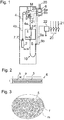
- FIG. 1 illustrates an elevator according to a preferred embodiment.
- the elevator comprises a hoistway S, and a car 1 and a counterweight 2 vertically movable in the hoistway S.
- the elevator further comprises a rotatable drive member 3 and one or more suspension ropes 4 interconnecting the car 1 and counterweight 2 and passing over said rotatable drive member 3, which engages the rope(s) in a force transmitting manner.
- Each of the suspension rope(s) 4 has a first rope section 4a on the first side of the drive member 3 and a second rope section 4b on the second side of the drive member 3, the first section(s) 4a of the rope(s) 4 being connected to the car 1 to suspend the car 1, and the second section(s) 4b of the rope(s) 4 being connected to the counterweight 2 to suspend the counterweight 2.
- the end of the second rope section 4b is fixed on the counterweight 2 and the end of the first rope section is fixed on the car 1.
- the elevator further comprises a drive machinery b, M,6,21,22 controlling rotation of the drive member 3.
- the drive machinery b,M,6,21,22 comprises one or more brakes b for braking the drive member 3 and a motor M for rotating the drive member 3.
- the drive machinery further comprises a control unit 6 connected with electrical connections 21,23 to the brake(s) b and the motor M via which connections it can control the brake(s) b and the motor M.
- Said electrical connection 23 is preferably electrical power supply for the motor M and said electrical connection 21 is preferably electrical power supply for the brake(s) b.
- the brake(s) are preferably mechanical brake(s).
- the brake(s) is/are preferably arranged to act on the drive member 3 during the braking by frictional engagement either directly or via a component connected to rotate with the drive member 3.
- the brake(s) is/are preferably so called machine brake(s).
- the drive machinery b,M,6,21,22 comprises an elevator control 6, which comprises a frequency converter 6a and a monitoring unit 6b.
- the elevator further comprises a sensing means 7,7' mounted on the counterweight 2 and arranged to sense state of an elevator component 4b.
- the sensing means 7,7' are in this embodiment rope tension sensing means 7,7' mounted on the counterweight 2 arranged to sense tension of the second section(s) 4b of the rope(s) 4.
- the system can notice a slack rope - situation on the counterweight side. Slackening of ropes 4 on the counterweight side indicates that the force balance at the rotatable drive member 3 is unsafe. For enabling prevention of the situation getting more dangerous and even to stalling, such situation is reacted to by the drive machinery b,M,6,21,22.
- the sensing means 7,7' (in this case the rope tension sensing means 7,7') mounted on the counterweight 2 are connected with the drive machinery b,M,6,21,22 functionally such that a predetermined state change (in this case reduced rope tension, i.e. a rope tension which is below a certain limit, of the second rope section(s) 4b sensed by the rope tension sensing means 7,7'), triggers the drive machinery b,M,6,21,22 to brake rotation of the drive member 3 and/or to stop the rotating of the drive member 3.
- a predetermined state change in this case reduced rope tension, i.e. a rope tension which is below a certain limit, of the second rope section(s) 4b sensed by the rope tension sensing means 7,7'
- Said rope(s) 4 comprise electrically conducting members 5, each extending continuously along the length of the rope 4, the electrically conducting members 5 forming an electrically conducting connection between the car 1 and counterweight 2, via which electrically conducting connection said functional connection is established.
- the electrically conducting connection between the car 1 and counterweight 2 makes it possible that said functional connection is routed from counterweight 2 to the car 1 and further to the drive machinery b,M,6,21,22.
- the rope tension sensing means 7,7' are electrically connected to said electrically conducting members 5.
- the elevator furthermore comprises a car unit 8,8' mounted on the car 1, which car unit 8,8' is electrically connected to the rope tension sensing means 7,7' by said electrically conducting members 5.
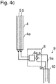
- Figures 4 (4a to 4c) and 5 (5a to 5c) illustrate alternative configurations for the elevator of Figure 1 .
- the elevator furthermore comprises a safety circuit 9 (also referred to as a safety chain) breaking of which causes the drive machinery (b,M,6,21,22) to brake rotation of the drive member 3 and/or to stop rotating the drive member 3.
- the breaking of the safety circuit 9 causes that power supply 20 to the frequency converter 6a is broken (the power supply 20 being thereby also a power supply of the motor M) and/or that the power supply 21 of the actuator(s) of the brake(s) b is broken, which actuator(s) keep(s) the brake(s) b normally in released state when powered.
- the safety circuit 9 is connected to a contactor 22, which may be in the form of a relay, controlling switches of the power supply lines 20 and 21, as illustrated in the Figure 1 .
- the safety circuit 9 is under voltage and the breaking thereof is arranged to cause the contactor 22 to release said switches to opened state and thereby to break the power supply of these power lines 20,21.
- Reduced rope tension of the second rope section(s) 4b sensed by the rope tension sensing means 7,7' is arranged to trigger via the electrically conducting connection between the car 1 and counterweight 2 the car unit 8,8' to break the safety circuit 9.
- the car unit 8,8' is arranged to break the safety circuit 9 if reduced rope tension of the second rope section(s) 4b is sensed by the rope tension sensing means 7,7'.
- it preferably comprises a relay 8a,8a' operating a safety switch s of the safety circuit.
- the relay 8a,8a' is preferably a normally closed -type relay (NC), for instance relay in the form of a SPSTNC -type relay.
- the safety circuit 9 connects the car unit 8,8' and the drive machinery. Thereby, said functional connection is established via said electrically conducting connection between the car 1 and counterweight 2, and further via the car unit 8,8', and the safety chain 9.
- the safety chain has a conductor 9a,9b passing away from the car inside a traveling cable 10 connected to the elevator car 1.
- FIGs 2 and 3 illustrate a preferred structure for an individual rope 4.
- Each of the aforementioned electrically conducting members 5 is in this case a load bearing member 5 of a rope 4, which load bearing member 5 is made of composite material comprising reinforcing fibers f embedded in a polymer matrix m, which reinforcing fibers f are carbon fibers. With this material selection, the member 5 can provide good properties in terms of load bearing and electrical conductivity. Thereby, there is no need for embedding a conducting element in the rope 4, which does not contribute in the essential load bearing function of the rope 4.
- the aforementioned one or more ropes may comprise several of the ropes 4 as illustrated in Figures 2 and 3 .
- each of the ropes 4 has exactly two of the load bearing members 5 as disclosed in Figure 2 , but each rope 4 may have one or several of such load bearing members 5. Then, any two of the load bearing members 5 of the ropes 4, irrespective of whether they are comprised in the same rope 4 or in different ropes 4, can form a part of an electrical circuit which is formed between the counterweight 2 and the car 1. It is however preferable that there are at least two of such load bearing members 5 comprised in one rope which both form part of the aforementioned electrical circuit which is formed between the counterweight 2 and the car 1. In this way, the electrical connections are simple to provide, and the functional connection can be provided even with only one rope.
- the ropes 4 are belt-like, as thereby it is easy to embed several of said electrically conducting/load bearing members 5 in one rope 4 to be spaced apart from each other in width direction of the rope 4.
- Several other alternatives for the structure of the rope 4 are illustrated and described in document WO2009090299A1 .
- the electrically conducting members 5 forming the electrically conducting connection between the car 1 and counterweight 2, each of which is in this case a load bearing member 5 of a rope 4, are embedded in polymer coating p immediately against and surrounding the electrically conducting member 5, which polymer coating p isolates each electrically conducting member 5 from any other electrically conducting member of the rope 4 as well as from components external to the rope 4 with which component the conducting member 4 could otherwise get into contact.
- the coating p is preferably of polymer, most preferably of elastic polymer, such as of polyurethane, as it provides good wear resistance, protection and good friction properties, for instance for frictional traction contact with the rotatable drive member 3.
- the coating p forms in these embodiments the surface of the rope.
- rope 4 is preferably in the form of a belt, and thereby has a width w substantially larger than the thickness t thereof as presented in figure 2 .
- the width/thickness ratio of the rope is at least 2 or more, preferably at least 4, even more preferably at least 5 or more.
- the width/thickness ratio(s) of said load bearing member(s) 5 is/are at least 2, preferably at least 3 or more.
- the rope 4 is made to contain only one load bearing member 5, then it is preferable that this ratio is 5 or more. It is preferable, that all the load bearing member(s) 5 of the rope (irrespective whether there is only one or more of them in the rope) cover together majority, preferably 70% or over, more preferably 75% or over, most preferably 80% or over, of the width of the rope. Thus, the width of the rope is effectively utilized for the function of load bearing.
- the preferred composite structure of the load bearing member 5 is preferably more specifically as follows.
- the load bearing member 5, as well as its fibers f are parallel with the longitudinal direction the rope, and untwisted as far as possible.
- Individual reinforcing fibers f are bound into a uniform load bearing member with the polymer matrix m.
- each load bearing member 5 is one solid elongated rodlike piece.
- the reinforcing fibers f are preferably long continuous fibers in the longitudinal direction of the rope 4, the fibers f preferably continuing for the whole length of the load bearing member 5 as well as the rope 4.
- Preferably as many fibers f as possible, most preferably substantially all the fibers f of the load bearing member 5 are oriented parallel with the rope, as far as possible in untwisted manner in relation to each other.
- the structure of the load bearing member 5 can be made to continue the same as far as possible in terms of its cross-section for the whole length of the rope.
- the reinforcing fibers f are preferably distributed in the aforementioned load bearing member 5 as evenly as possible, so that the load bearing member 5 would be as homogeneous as possible in the transverse direction of the rope.
- An advantage of the structure presented is that the matrix m surrounding the reinforcing fibers f keeps the interpositioning of the reinforcing fibers f substantially unchanged. It equalizes with its slight elasticity the distribution of a force exerted on the fibers, reduces fiber-fiber contacts and internal wear of the rope, thus improving the service life of the rope.
- the composite matrix m into which the individual fibers f are distributed as evenly as possible, is most preferably of epoxy resin, which has good adhesiveness to the reinforcement fibers f and which is known to behave advantageously with carbon fiber.
- e.g. polyester or vinyl ester can be used, but alternatively any other suitable alternative material can be used.
- Figure 3 presents a partial cross-section of the load bearing member 5 close to the surface thereof as viewed in the longitudinal direction of the rope presented inside the circle in the figure, according to which cross-section the reinforcing fibers f of each load bearing member 5 are preferably organized in the polymer matrix m.
- the rest (not showed parts) of the load bearing member 5 has a similar structure.
- Figure 3 presents also how the individual reinforcing fibers f are substantially evenly distributed in the polymer matrix m, which surrounds the fibers and which is fixed to the fibers f.
- the polymer matrix m fills the areas between individual reinforcing fibers f and binds substantially all the reinforcing fibers f that are inside the matrix m to each other as a uniform solid substance.
- a chemical bond exists between, preferably all, the individual reinforcing fibers f and the matrix m, one advantage of which is uniformity of the structure.
- the polymer matrix m is preferably of a hard non-elastomer. It can comprise additives for fine-tuning the properties of the matrix as an addition to the base polymer.
- the reinforcing fibers f being in the polymer matrix means here that the individual reinforcing fibers are bound to each other with the polymer matrix m, e.g. in the manufacturing phase by immersing them together in the fluid material of the polymer matrix. In this case the gaps of individual reinforcing fibers bound to each other with the polymer matrix comprise the polymer of the matrix. In this way a great number of reinforcing fibers bound to each other in the longitudinal direction of the rope are distributed in the polymer matrix.
- the reinforcing fibers are preferably distributed substantially evenly in the polymer matrix such that the load bearing member is as homogeneous as possible when viewed in the direction of the cross-section of the rope. In other words, the fiber density in the cross-section of the load bearing member does not therefore vary substantially.
- the reinforcing fibers f together with the matrix m form a uniform load bearing member, inside which abrasive relative movement does not occur when the rope is bent.
- the individual reinforcing fibers of the load bearing member 5 are mainly surrounded with polymer matrix m, but random fiber-fiber contacts can occur because controlling the position of the fibers in relation to each other in their simultaneous impregnation with polymer is difficult, and on the other hand, perfect elimination of random fiber-fiber contacts is not necessary from the viewpoint of the functioning of the invention. If, however, it is desired to reduce their random occurrence, the individual reinforcing fibers f can be pre-coated such that a polymer coating is around them already before the binding of individual reinforcing fibers to each other.
- the individual reinforcing fibers of the load bearing member can comprise material of the polymer matrix around them such that the polymer matrix is immediately against the reinforcing fiber but alternatively a thin coating, e.g. a primer arranged on the surface of the reinforcing fiber in the manufacturing phase to improve chemical adhesion to the matrix material, can be in between.
- Individual reinforcing fibers are distributed evenly in the load bearing member 5 such that the gaps of individual reinforcing fibers f are filled with the polymer of the matrix m. Most preferably the majority, preferably substantially all of the gaps of the individual reinforcing fibers f in the load bearing member 5 are filled with the polymer of the matrix m.
- the matrix m of the load bearing member 5 is most preferably hard in its material properties.
- a hard matrix m helps to support the reinforcing fibers f, especially when the rope bends, preventing buckling of the reinforcing fibers f of the bent rope, because the hard material supports the fibers f.
- the polymer matrix is hard, and in particular non-elastomeric.
- the most preferred materials are epoxy resin, polyester, phenolic plastic or vinyl ester.
- the polymer matrix is preferably so hard that its module of elasticity (E) is over 2 GPa, most preferably over 2.5 GPa.
- the module of elasticity (E) is preferably in the range 2.5-10 GPa, most preferably in the range 2.5-3.5 GPa.
- the matrix m which can provide these material properties.
- Preferably over 50% of the surface area of the cross-section of the load bearing member 5 is of the aforementioned reinforcing fiber, preferably such that 50%-80% is of the aforementioned reinforcing fiber, more preferably such that 55%-70% is of the aforementioned reinforcing fiber, and substantially all the remaining surface area is of polymer matrix. Most preferably, this is carried out such that approx. 60% of the surface area is of reinforcing fiber and approx. 40% is of matrix material (preferably epoxy material). In this way a good longitudinal stiffness for the load bearing member 5 as well as good electrical conductivity are achieved.
- Figures 4 (4a to 4c) and 5 (5a to 5c) illustrate alternative configurations for the elevator of Figure 1 .
- Figures 4a to 4c illustrate a configuration where each of said electrically conducting members 5 forms part of an electrical circuit breaking of which causes breaking of a safety circuit 9 of the elevator, and the rope tension sensing means 7 are configured to break the electrical circuit between the car 1 and counterweight 2 if reduced rope tension of the second rope section(s) 4b is sensed by the rope tension sensing means 7.
- the sensing means 7 comprise a switch component 7a configured to normally close the electrical circuit between the car 1 and counterweight 2 formed at least partially by two electrically conducting members 5 of the ropes (in this case by two conducting members 5 of one and the same rope 4 and to open said electrical circuit in case of reduced rope tension of the second rope section(s) 4b. It is preferable that the electrical circuit is under voltage when it is closed. If said electrical circuit between the car 1 and counterweight 2 is broken the car unit 8 is arranged to break the safety circuit 9.
- reduced rope tension of the second rope section(s) 4b sensed by the rope tension sensing means 7 is arranged to break said conducting connection between the car 1 and counterweight 2 and thereby trigger via the electrically conducting connection between the car 1 and counterweight 2 the car unit 8,8' to break the safety circuit 9 and thereby to trigger said braking of the drive machinery (b,M,6,21,22) and/or to stopping the rotating of the drive member 3.
- the switch component 7a is preferably spring-actuated, the rope tension working against the force of the spring(s) 7c, and configured such that in case of reduced rope tension the spring force overcomes the rope tension and actuates the switch to move into open state. As illustrated in Figure 4b the ropes are mounted via said springs 7b.
- said springs 7b are mounted between the hitch plate 7c and the counterweight frame 2a to urge the hitch plate towards the tension sensor 7a.
- the spring force overcomes the rope tension force and moves the hitch plate 7c against the tension sensor 7a, which then brakes the electrical circuit between the car 1 and counterweight 2 formed at least partially by two electrically conducting members 5.
- the car unit 8, in particular a relay 8a thereof opens a safety switch s of the safety chain 9 in response to breaking of the electrical circuit between the car 1 and counterweight 2 formed at least partially by two electrically conducting members 5, which has the consequence that the power supply 20 to the frequency converter 6a to break and/or the power supply 21 of the actuator(s) of the brake(s) b to break.
- Figures 5a to 5c illustrate a configuration where each said electrically conducting member(s) 5 forming said electrically conducting connection between the car 1 and counterweight 2 forms part of an electrical circuit between the car 1 and counterweight 2, and the rope tension sensing means 7' are configured to change an electrical property of the circuit between the car 1 and counterweight 2 if reduced rope tension of the second rope section(s) 4b is sensed by the rope tension sensing means 7', and a predefined change in the electrical properties is configured to cause breaking of a safety circuit 9 of the elevator.
- the car unit 8' is arranged to break the safety circuit 9 if it detects a predefined change in the electrical properties of the electrical circuit between the car 1 and counterweight 2.
- Said sensing means 7' comprise one or more rope tension sensors 7a' configured to change the electrical properties of the circuit when the sensor(s) sense reduced rope tension.
- the sensor(s) 7a' is/are force sensor(s) 7a' via which the rope(s) (4) suspend(s) the counterweight, in particular via which the second section(s) of the rope(s) is/are fixed to the counterweight.
- the rope tension is transmitted to the force sensor(s) 7a'.
- Said change in the electrical properties may be for instance a change in resistance caused by change in force directed to the force sensor(s) 7a'.
- the car unit 8' comprises a monitoring unit 8b' controlling a safety relay 8a'.
- the car unit 8' in particular the monitoring unit 8b' is configured to control said relay 8a' to open a safety switch s of the safety chain 9 in response to the detected change in the electrical property of the electrical circuit at the car end, which has the consequence that the power supply 20 to the frequency converter 6a to break and/or the power supply 21 of the actuator(s) of the brake(s) b to break.
- the term load bearing member of a rope refers to the part that is elongated in the longitudinal direction of the rope, and which part is able to bear without breaking a significant part of the load exerted on the rope in question in the longitudinal direction of the rope.
- the aforementioned load exerted on the rope causes tension on the load bearing member in the longitudinal direction of the load bearing member, which tension can be transmitted inside the load bearing member in question all the length of the load bearing member, e.g. from one end of the load bearing member to the other end of it.
- said reduced rope tension is considered to mean a rope tension, which is below a certain limit.
- Said limit is preferably predetermined substantially below a rope tension which is considered to be within normal variation of the rope tension of the second rope section(s) being sensed.
- the elevator comprises two of said electrically conducting members forming an electrically conducting connection between the car and counterweight, which are connected to each other by said tension sensing means, and forming consecutive parts of an electrical circuit between the car and counterweight.
- This is a preferred configuration, but some aspects of the configuration can be changed if desired.
- the number of said electrically conducting members could be greater or smaller. It is even possible to realize an electrically conducting connection functioning as described with only one of said electrically conducting members.
- the tension sensing means is preferable to equip with a battery for providing voltage, which is then utilized for sending an electrical signal to the drive machinery via the connection between the car and the counterweight so as to trigger the functions defined elsewhere in the application.
- a predetermined state change sensed by the sensing means is arranged to trigger via said electrically conducting connection the drive machinery to brake rotation of the drive member and/or to stop rotating the drive member.
- reduced rope tension of the second rope section(s) 4b sensed by the rope tension sensing means 7,7' is arranged to trigger via said electrically conducting connection the drive machinery (b,M,6,21,22) to brake rotation of the drive member 3 and/or to stop rotating the drive member 3.
- said sensing means 7,7' mounted on the counterweight 2 and arranged to sense state of an elevator component 4b are in the form of a rope tension sensing means 7,7' mounted on the counterweight 2 and arranged to sense tension of the second section(s) 4b of the rope(s) 4, said predetermined state change being a reduced rope tension, i.e. the predetermined state change equals to reduction of rope tension below a certain limit.
- said sensing means 7,7' may be alternatively arranged to sense state of a different component than the second section(s) 4b of the rope(s), for example state of a brake acting on guide rails of the counterweight, the brake being in particular a safety gear, mounted on the counterweight 2.
- the component may be the guide rail of the counterweight 2 or a component which is dependent of counterweights 2 position relative to its guide rails, whereby (direct or indirect) sensing of counterweight derailment can be provided.
- derailment is quickly noticed and reacted to.
Landscapes
- Engineering & Computer Science (AREA)
- Civil Engineering (AREA)
- Mechanical Engineering (AREA)
- Structural Engineering (AREA)
- Lift-Guide Devices, And Elevator Ropes And Cables (AREA)
Description
- The invention relates to an elevator, in particular to an elevator which is meant for transporting passengers and/or goods.
- In elevators, the counterweight and the car are interconnected with suspension ropes, which pass over a rotatable drive member. The rotatable drive member is usually in the form of a drive wheel. It is typically rotated with an electric motor. The rotatable drive member engages the ropes generally by friction and/or positive locking, whereby it can, by its rotation, make the ropes run from one side of the rotatable drive member to the other side thereof. The counterweight forms a force on the ropes on the counterweight-side of the rotatable drive member acting on opposite direction than the corresponding forces caused by the car on the car-side of the rotatable drive member. In some elevators the engagement between the ropes and the drive member is strong enough to support the whole weight of the car even without the effect of the counterweight. This may be the case for example if the frictional engagement between the ropes and the rotatable drive member is very firm or if the elevator uses toothed belts as the suspension ropes. An engagement this firm may be dangerous if for some reason the effect of the counterweight is lost. For example, if the counterweight is stuck immovable in the hoistway this causes a risk that subsequent lifting of the car upwards may result in a drop of the car when the engagement is ultimately lost (stalling). In case the counterweight gets immovable, from thereon the rotation of the drive member to the car-upwards-direction will move the car upwards and wind slack rope on the counterweight-side of the drive member. Should the engagement in such a slack rope -situation be lost, the car would drop. In most elevators the counterweight and the car are furthermore interconnected with a compensation roping passing around a diverting wheel located in the lower parts of the hoistway. The compensation roping is generally enough to prevent the above described dangerous situation from developing.
- Elevators having a firm engagement between the drive member and the ropes and designed without a compensation roping passing around a diverting wheel located in the lower parts of the hoistway, on the other hand, are particularly vulnerable to dangerous stalling in such slack rope -situations. A problem with prior art elevators has been a lack of simple configuration for reacting quickly to counterweight-related safety issues.
- In addition to stalling, also other kinds of counterweight-related safety issues may exist. Such issues may be for instance the danger of derailment of the counterweight and the activation of the safety gear of the counterweight. In prior art, counterweight-related safety issues have not been solved in a simple way.
- Related prior art has been disclosed in documents
JPS5511913U US6123176A andUS2004/026177A1 . DocumentUS6123176A discloses an elevator comprising the features of the preamble ofclaim 1. - The object of the invention is, inter alia, to solve one or more of the previously described drawbacks as well as to achieve advantages discussed later in the description of the invention.
- An object of the invention is to introduce a new elevator, which is improved in terms of its safety and simplicity. An object is, in particular, to provide a new elevator where an unsafe situation related to functioning of the counterweight, in particular a stalling situation, is quickly noticed and reacted to. An object is to provide an elevator with configuration that is simple and efficient in providing said quick notice and reaction. In case of a stalling situation, it is in particular an objective to prevent the stalling situation from developing further with certain actions, which are efficient for ensuring safety. Embodiments are presented, inter alia, where the elevator can be arranged to work without a roping passing around a diverting wheel located in the lower parts of the hoistway.
- It is brought forward a new elevator comprising a hoistway, a car and a counterweight vertically movable in the hoistway, and a rotatable drive member. The elevator further comprises one or more suspension ropes interconnecting the car and the counterweight and passing over the rotatable drive member. The elevator further comprises a drive machinery controlling rotation of the drive member, the drive machinery preferably comprising a brake for braking the drive member and a motor for rotating the drive member. The elevator further comprises a sensing means mounted on the counterweight and arranged to sense state of an elevator component. Said rope(s) comprise(s) electrically conducting member(s) extending continuously along the length of the rope(s), the electrically conducting member(s) forming an electrically conducting connection between the car and counterweight. Said sensing means are functionally connected with the drive machinery via said electrically conducting connection between the car and counterweight such that a predetermined state change sensed by the sensing means triggers the drive machinery to brake rotation of the drive member and/or to stop rotating the drive member. Hereby, a simple arrangement is provided, which can respond quickly to a state change of an elevator component. Thus, state of an elevator component which is connected to or part of the counterweight can be directly observed, and predetermined actions triggered without means of communication, which are in addition and separate of the essential elevator components. This is because the rope(s) interconnecting the car and counterweight are used to establish a portion of the functional connection between the sensing means and the drive machinery.
- Each of said electrically conducting member(s) is a load bearing member of the rope in question. Thereby, there is no need for embedding conducting elements in the ropes, which do not contribute in the essential load bearing function of the rope. The load bearing member is made of composite material comprising reinforcing fibers embedded in a polymer matrix, which reinforcing fibers are carbon fibers. With this material selection, the member can provide good properties in terms of load bearing and electrical conductivity. Then, it is preferable, that each of said at least one rope comprises a load bearing member or a plurality of load bearing members for bearing load in the longitudinal direction of the rope, which load bearing member(s) is/are made of composite material comprising reinforcing fibers embedded in a polymer matrix, which reinforcing fibers are carbon fibers, and in that each of said electrically conducting member(s) forming an electrically conducting connection between the car and counterweight is one of said load bearing members. Also, the ropes being of the carbon-fiber composite, they are light-weighted, and improve energy efficiency of the elevator. With this kind of ropes, the elevator is also particularly suitable for functioning without compensation ropes. Accordingly, it is preferable that the counterweight and the car are not interconnected with a compensation roping passing around a diverting wheel located in the lower parts of the hoistway. Thus, a safe and economical elevator configuration can be provided.
- In a further refined embodiment, said a predetermined state change equals to reduction of rope tension below a certain limit. In this embodiment, each of the suspension rope(s) has a first rope section on the first side of the drive member and a second rope section on the second side of the drive member, the first section(s) of the rope(s) being connected to the car to suspend the car, and the second section(s) of the rope(s) being connected to the counterweight to suspend the counterweight. The aforementioned sensing means are in the form of rope tension sensing means mounted on the counterweight and arranged to sense tension of the second section(s) of the rope(s). The rope tension sensing means are functionally connected with the drive machinery via said electrically conducting connection between the car and counterweight such that reduced rope tension of the second rope section(s) sensed by the rope tension sensing means triggers the drive machinery to brake rotation of the drive member and/or to stop rotating the drive member. In this way, further development of a dangerous situation can be stopped and stalling situation avoided. Hereby a threatening situation is stopped from developing further with actions which are efficient for ensuring safety. Hereby, the elevator can safely be arranged to work without a roping passing around a diverting wheel located in the lower parts of the hoistway.
- In a further refined embodiment, said rope(s) comprise(s) two of said electrically conducting members connected to each other by said sensing means, which are preferably tension sensing means as mentioned, and said electrically conducting members form consecutive parts of an electrical circuit between the car and counterweight. Thus, a simple and well working configuration is established. The electrical circuit is preferably under voltage. The electrical circuit can this configuration simply be arranged to be under voltage provided for by a source external to the counterweight. Preferably, said two electrically conducting members are parallel load bearing members of a same belt-shaped rope, and adjacent and spaced apart in the width direction of the rope.
- In a further refined embodiment, each of said electrically conducting member(s) is embedded in polymer isolating the electrically conducting member from other electrically conducting member(s) of the rope. This polymer is preferably a coating forming also the surface of the rope.
- In a further refined embodiment, the elevator comprises a car unit mounted on the car, which car unit is electrically connected to the sensing means, which are preferably tension sensing means as mentioned, by said electrically conducting member(s). The sensing means are also electrically connected to the electrically conducting member(s) forming electrically conducting connection between the car and counterweight.
- In a further refined embodiment, the elevator comprises a safety circuit breaking of which is arranged to cause the drive machinery to brake rotation of the drive member and/or to stop rotating the drive member, in particular to break power supply of the motor and/or the power supply of the brake actuator(s) keeping the brake(s) in released state when powered, and in that a predetermined state change sensed by the sensing means, such as said reduced rope tension of the second rope section(s) sensed by the rope tension sensing means, is arranged to trigger via the electrically conducting connection between the car and counterweight the car unit to break the safety circuit, and thereby to trigger said braking of the drive machinery and/or to stopping the rotating of the drive member. In a further refined embodiment, particularly the car unit mentioned above is arranged to break the safety circuit if a predetermined state change, such as said reduced rope tension of the second rope section(s), is sensed by the sensing means. For this purpose, the car unit preferably comprises a relay operating a safety switch of the safety circuit.
- In a further refined embodiment, said sensing means comprise one or more rope tension sensors.
- In a further refined embodiment, said two electrically conducting members extend parallelly. They are preferably comprised in the same rope, but they may alternatively be comprised in different ropes.
- In a further refined embodiment, the sensing means, which are preferably tension sensing means as mentioned, are electrically connected to the electrically conducting member(s) forming said electrically conducting connection between the car and counterweight at a first end thereof, and the car unit is electrically connected to the electrically conducting member(s) forming said electrically conducting connection between the car and counterweight at the car at a second end thereof, and the electrically conducting member(s) continues unbroken between said first and second end. In a further refined embodiment, the safety circuit extends between the car unit and the drive machinery.
- In a further refined embodiment, the elevator comprises a traveling cable connected to the elevator car inside which the safety circuit passes.
- In a further refined embodiment, each of said at least one rope is belt-like, whereby it is easy to embed several of said electrically conducting members in the rope spaced apart from each other.
- In a further refined embodiment, the module of elasticity (E) of the polymer matrix is over 2 GPa, most preferably over 2.5 GPa, yet more preferably in the range 2.5-10 GPa, most preferably of all in the range 2.5-3.5 GPa. In this way a structure is achieved wherein the matrix essentially supports the reinforcing fibers, in particular from buckling. One advantage, among others, is a longer service life.
- In a further refined embodiment, the load-bearing member(s) of the rope cover(s) over proportion 50% of the cross-section of the rope. Thereby, a high tensile stiffness can be facilitated.
- In a further refined embodiment, the load-bearing member(s) of the rope cover(s) majority, preferably 60% or over, more preferably 65% or over of the width of the rope. In this way at least majority of the width of the rope will be effectively utilized and the rope can be formed to be light and thin in the bending direction for reducing the bending resistance.
- In a further refined embodiment, the counterweight and the car are not interconnected with a compensation roping passing around a diverting wheel located in the lower parts of the hoistway. Thereby, the elevator is specifically sensitive to dangers related to slack rope and stalling. Safety of this kind of elevator can be increased with the rope tension sensing means as defined.
- In a further refined embodiment, said load bearing member(s) is/are parallel with the longitudinal direction of the rope. Thereby, the load bearing members are oriented in the direction of the force when the rope is pulled, which increases the tensile stiffness and strength of the rope. Furthermore, it is preferred that said reinforcing fibers are parallel with the longitudinal direction of the load bearing member. In particular, the reinforcing fibers of the same load bearing member are preferably essentially untwisted in relation to each other. Thereby, the reinforcing fibers are oriented in the direction of the force when the load bearing member in question is pulled. This gives the load bearing members an excellent tensile stiffness and strength.
- In a further refined embodiment, said rope(s) each comprise a plurality of parallel load bearing members adjacent and spaced apart in the width direction of the belt-shaped rope.
- In a further refined embodiment, said load bearing member(s) is/are embedded in a common elastomeric coating of the rope in question. The ropes being belt-like, they provide a large surface area enabling efficient force transmission, e.g. by frictional engagement. This can be facilitated by elastomeric coating. In a preferred embodiment, the coating forms the surface of the rope.
- In a further refined embodiment, individual reinforcing fibers are homogeneously distributed in said polymer matrix. Preferably, over 50% of the cross-sectional square area of the load-bearing part consists of said reinforcing fiber.
- In a further refined embodiment, the counterweight does not comprise a battery or any other kind of power source mounted on it for providing power for the sensing means.
- In further refined embodiment of a first type, each of said electrically conducting member(s) forms part of an electrical circuit between the car and counterweight breaking of which causes breaking of a safety circuit of the elevator, and the sensing means, which are preferably tension sensing means as mentioned, are configured to break the electrical circuit between the car and counterweight if a predetermined state change, e.g. reduced rope tension of the second rope section(s), is sensed by the sensing means. Preferably, the car unit is arranged to break the safety circuit if said circuit between the car and counterweight is broken. Preferably, said sensing means comprise a switch component configured to normally close the electrical circuit between the car and counterweight, which electrical circuit is formed at least partially by two electrically conducting members of the rope(s), and to open said electrical circuit in case of reduced rope tension of the second rope section(s). Preferably, the switch component is spring-actuated, rope tension being configured to work against the force of the spring(s), such that in case of reduced rope tension the spring force overcomes the rope tension and actuates the switch to move into open state.
- In further refined embodiment of a second type, each said electrically conducting member(s) forms part of an electrical circuit between the car and counterweight, and the sensing means, which are preferably tension sensing means as mentioned, are configured to change an electrical property of the electrical circuit between the car and counterweight if a predetermined state change, e.g. said reduced rope tension of the second rope section(s), is sensed by the sensing means, and a predefined change in the electrical properties is configured to cause breaking of a safety circuit of the elevator. Preferably, the car unit is arranged to break the safety circuit if it detects a predefined change in the electrical properties of the electrical circuit between the car and counterweight. Preferably, said sensing means comprise one or more force sensors via which the rope(s) suspend(s) the counterweight, in particular via which the second section(s) of the rope(s) is/are fixed to the counterweight.
- The elevator as described anywhere above is preferably, but not necessarily, installed inside a building. It is of the type where the elevator car is arranged to serve two or more landings. The car preferably responds to calls, such as destination calls from landing and/or destination commands from inside the car so as to serve persons on the landing(s) and/or inside the elevator car. Preferably, the car has an interior space suitable for receiving a passenger or passengers, and the car can be provided with a door for form ing a closed interior space. Thereby, it is well suitable for serving passengers.
- In the following, the present invention will be described in more detail by way of example and with reference to the attached drawings, in which
-
Figure 1 illustrates schematically an elevator according to a preferred embodiment of the invention. -
Figure 2 illustrates schematically a rope of the elevator. -
Figure 3 illustrates an enlarged partial view of the cross section of a load bearing member of the rope. -
Figures 4a to 4c illustrate further preferred details for the elevator ofFigure 1 according to a first alternative. -
Figures 5a to 5c illustrate further preferred details for the elevator ofFigure 1 according to a second alternative. -
Figure 1 illustrates an elevator according to a preferred embodiment. The elevator comprises a hoistway S, and acar 1 and acounterweight 2 vertically movable in the hoistway S. The elevator further comprises arotatable drive member 3 and one ormore suspension ropes 4 interconnecting thecar 1 andcounterweight 2 and passing over saidrotatable drive member 3, which engages the rope(s) in a force transmitting manner. Each of the suspension rope(s) 4 has afirst rope section 4a on the first side of thedrive member 3 and asecond rope section 4b on the second side of thedrive member 3, the first section(s) 4a of the rope(s) 4 being connected to thecar 1 to suspend thecar 1, and the second section(s) 4b of the rope(s) 4 being connected to thecounterweight 2 to suspend thecounterweight 2. In this embodiment, the end of thesecond rope section 4b is fixed on thecounterweight 2 and the end of the first rope section is fixed on thecar 1. - The elevator further comprises a drive machinery b, M,6,21,22 controlling rotation of the
drive member 3. The drive machinery b,M,6,21,22 comprises one or more brakes b for braking thedrive member 3 and a motor M for rotating thedrive member 3. The drive machinery further comprises acontrol unit 6 connected withelectrical connections electrical connection 23 is preferably electrical power supply for the motor M and saidelectrical connection 21 is preferably electrical power supply for the brake(s) b. The brake(s) are preferably mechanical brake(s). The brake(s) is/are preferably arranged to act on thedrive member 3 during the braking by frictional engagement either directly or via a component connected to rotate with thedrive member 3. The brake(s) is/are preferably so called machine brake(s). The drive machinery b,M,6,21,22 comprises anelevator control 6, which comprises afrequency converter 6a and amonitoring unit 6b. - The elevator further comprises a sensing means 7,7' mounted on the
counterweight 2 and arranged to sense state of anelevator component 4b. The sensing means 7,7' are in this embodiment rope tension sensing means 7,7' mounted on thecounterweight 2 arranged to sense tension of the second section(s) 4b of the rope(s) 4. Thereby, the system can notice a slack rope - situation on the counterweight side. Slackening ofropes 4 on the counterweight side indicates that the force balance at therotatable drive member 3 is unsafe. For enabling prevention of the situation getting more dangerous and even to stalling, such situation is reacted to by the drive machinery b,M,6,21,22. For enabling reacting to an unsafe situation, the sensing means 7,7' (in this case the rope tension sensing means 7,7') mounted on thecounterweight 2 are connected with the drive machinery b,M,6,21,22 functionally such that a predetermined state change (in this case reduced rope tension, i.e. a rope tension which is below a certain limit, of the second rope section(s) 4b sensed by the rope tension sensing means 7,7'), triggers the drive machinery b,M,6,21,22 to brake rotation of thedrive member 3 and/or to stop the rotating of thedrive member 3. Said rope(s) 4 comprise electrically conductingmembers 5, each extending continuously along the length of therope 4, the electrically conductingmembers 5 forming an electrically conducting connection between thecar 1 andcounterweight 2, via which electrically conducting connection said functional connection is established. In particular, the electrically conducting connection between thecar 1 andcounterweight 2 makes it possible that said functional connection is routed fromcounterweight 2 to thecar 1 and further to the drive machinery b,M,6,21,22. - In the preferred embodiment, the rope tension sensing means 7,7' are electrically connected to said electrically conducting
members 5. The elevator furthermore comprises acar unit 8,8' mounted on thecar 1, whichcar unit 8,8' is electrically connected to the rope tension sensing means 7,7' by said electrically conductingmembers 5.Figures 4 (4a to 4c) and 5 (5a to 5c) illustrate alternative configurations for the elevator ofFigure 1 . In both of these more detailed embodiments, the elevator furthermore comprises a safety circuit 9 (also referred to as a safety chain) breaking of which causes the drive machinery (b,M,6,21,22) to brake rotation of thedrive member 3 and/or to stop rotating thedrive member 3. In particular, the breaking of thesafety circuit 9 causes thatpower supply 20 to thefrequency converter 6a is broken (thepower supply 20 being thereby also a power supply of the motor M) and/or that thepower supply 21 of the actuator(s) of the brake(s) b is broken, which actuator(s) keep(s) the brake(s) b normally in released state when powered. For this purpose thesafety circuit 9 is connected to acontactor 22, which may be in the form of a relay, controlling switches of thepower supply lines Figure 1 . Preferably, thesafety circuit 9 is under voltage and the breaking thereof is arranged to cause thecontactor 22 to release said switches to opened state and thereby to break the power supply of thesepower lines car 1 andcounterweight 2 thecar unit 8,8' to break thesafety circuit 9. In particular, thecar unit 8,8' is arranged to break thesafety circuit 9 if reduced rope tension of the second rope section(s) 4b is sensed by the rope tension sensing means 7,7'. For this purpose, it preferably comprises arelay relay Figures 1 and4c and5c , in both of the embodiments, thesafety circuit 9 connects thecar unit 8,8' and the drive machinery. Thereby, said functional connection is established via said electrically conducting connection between thecar 1 andcounterweight 2, and further via thecar unit 8,8', and thesafety chain 9. As illustrated inFigures 1 and4c and5c , in both of the embodiments, on both sides of the safety switch s the safety chain has aconductor cable 10 connected to theelevator car 1. -
Figures 2 and 3 illustrate a preferred structure for anindividual rope 4. Each of the aforementionedelectrically conducting members 5 is in this case aload bearing member 5 of arope 4, which load bearingmember 5 is made of composite material comprising reinforcing fibers f embedded in a polymer matrix m, which reinforcing fibers f are carbon fibers. With this material selection, themember 5 can provide good properties in terms of load bearing and electrical conductivity. Thereby, there is no need for embedding a conducting element in therope 4, which does not contribute in the essential load bearing function of therope 4. The aforementioned one or more ropes may comprise several of theropes 4 as illustrated inFigures 2 and 3 . It is not necessary that each of theropes 4 has exactly two of theload bearing members 5 as disclosed inFigure 2 , but eachrope 4 may have one or several of suchload bearing members 5. Then, any two of theload bearing members 5 of theropes 4, irrespective of whether they are comprised in thesame rope 4 or indifferent ropes 4, can form a part of an electrical circuit which is formed between thecounterweight 2 and thecar 1. It is however preferable that there are at least two of suchload bearing members 5 comprised in one rope which both form part of the aforementioned electrical circuit which is formed between thecounterweight 2 and thecar 1. In this way, the electrical connections are simple to provide, and the functional connection can be provided even with only one rope. For this purpose, it is advantageous that theropes 4 are belt-like, as thereby it is easy to embed several of said electrically conducting/load bearing members 5 in onerope 4 to be spaced apart from each other in width direction of therope 4. Several other alternatives for the structure of therope 4 are illustrated and described in documentWO2009090299A1 . - As illustrated in
Figures 2 and 3 , the electrically conductingmembers 5 forming the electrically conducting connection between thecar 1 andcounterweight 2, each of which is in this case aload bearing member 5 of arope 4, are embedded in polymer coating p immediately against and surrounding the electrically conductingmember 5, which polymer coating p isolates each electrically conductingmember 5 from any other electrically conducting member of therope 4 as well as from components external to therope 4 with which component the conductingmember 4 could otherwise get into contact.' The coating p is preferably of polymer, most preferably of elastic polymer, such as of polyurethane, as it provides good wear resistance, protection and good friction properties, for instance for frictional traction contact with therotatable drive member 3. The coating p forms in these embodiments the surface of the rope. - As mentioned,
rope 4 is preferably in the form of a belt, and thereby has a width w substantially larger than the thickness t thereof as presented infigure 2 . This makes it well suitable for elevator use as bending of the rope is necessary in most elevators. So as to give a turning radius well suitable for elevator use, it is preferable that the width/thickness ratio of the rope is at least 2 or more, preferably at least 4, even more preferably at least 5 or more. Furthermore, so as to give a turning radius well suitable for elevator use, it is preferable that the width/thickness ratio(s) of said load bearing member(s) 5 is/are at least 2, preferably at least 3 or more. If therope 4 is made to contain only oneload bearing member 5, then it is preferable that this ratio is 5 or more. It is preferable, that all the load bearing member(s) 5 of the rope (irrespective whether there is only one or more of them in the rope) cover together majority, preferably 70% or over, more preferably 75% or over, most preferably 80% or over, of the width of the rope. Thus, the width of the rope is effectively utilized for the function of load bearing. - The preferred composite structure of the
load bearing member 5 is preferably more specifically as follows. Theload bearing member 5, as well as its fibers f are parallel with the longitudinal direction the rope, and untwisted as far as possible. Individual reinforcing fibers f are bound into a uniform load bearing member with the polymer matrix m. Thus, eachload bearing member 5 is one solid elongated rodlike piece. The reinforcing fibers f are preferably long continuous fibers in the longitudinal direction of therope 4, the fibers f preferably continuing for the whole length of theload bearing member 5 as well as therope 4. Preferably as many fibers f as possible, most preferably substantially all the fibers f of theload bearing member 5 are oriented parallel with the rope, as far as possible in untwisted manner in relation to each other. Thus the structure of theload bearing member 5 can be made to continue the same as far as possible in terms of its cross-section for the whole length of the rope. The reinforcing fibers f are preferably distributed in the aforementionedload bearing member 5 as evenly as possible, so that theload bearing member 5 would be as homogeneous as possible in the transverse direction of the rope. An advantage of the structure presented is that the matrix m surrounding the reinforcing fibers f keeps the interpositioning of the reinforcing fibers f substantially unchanged. It equalizes with its slight elasticity the distribution of a force exerted on the fibers, reduces fiber-fiber contacts and internal wear of the rope, thus improving the service life of the rope. The composite matrix m, into which the individual fibers f are distributed as evenly as possible, is most preferably of epoxy resin, which has good adhesiveness to the reinforcement fibers f and which is known to behave advantageously with carbon fiber. Alternatively, e.g. polyester or vinyl ester can be used, but alternatively any other suitable alternative material can be used.Figure 3 presents a partial cross-section of theload bearing member 5 close to the surface thereof as viewed in the longitudinal direction of the rope presented inside the circle in the figure, according to which cross-section the reinforcing fibers f of eachload bearing member 5 are preferably organized in the polymer matrix m. The rest (not showed parts) of theload bearing member 5 has a similar structure.Figure 3 presents also how the individual reinforcing fibers f are substantially evenly distributed in the polymer matrix m, which surrounds the fibers and which is fixed to the fibers f. The polymer matrix m fills the areas between individual reinforcing fibers f and binds substantially all the reinforcing fibers f that are inside the matrix m to each other as a uniform solid substance. A chemical bond exists between, preferably all, the individual reinforcing fibers f and the matrix m, one advantage of which is uniformity of the structure. To strengthen the chemical bond, there can be, but not necessarily, a coating (not presented) of the actual fibers between the reinforcing fibers and the polymer matrix m. The polymer matrix m is preferably of a hard non-elastomer. It can comprise additives for fine-tuning the properties of the matrix as an addition to the base polymer. The reinforcing fibers f being in the polymer matrix means here that the individual reinforcing fibers are bound to each other with the polymer matrix m, e.g. in the manufacturing phase by immersing them together in the fluid material of the polymer matrix. In this case the gaps of individual reinforcing fibers bound to each other with the polymer matrix comprise the polymer of the matrix. In this way a great number of reinforcing fibers bound to each other in the longitudinal direction of the rope are distributed in the polymer matrix. The reinforcing fibers are preferably distributed substantially evenly in the polymer matrix such that the load bearing member is as homogeneous as possible when viewed in the direction of the cross-section of the rope. In other words, the fiber density in the cross-section of the load bearing member does not therefore vary substantially. The reinforcing fibers f together with the matrix m form a uniform load bearing member, inside which abrasive relative movement does not occur when the rope is bent. The individual reinforcing fibers of theload bearing member 5 are mainly surrounded with polymer matrix m, but random fiber-fiber contacts can occur because controlling the position of the fibers in relation to each other in their simultaneous impregnation with polymer is difficult, and on the other hand, perfect elimination of random fiber-fiber contacts is not necessary from the viewpoint of the functioning of the invention. If, however, it is desired to reduce their random occurrence, the individual reinforcing fibers f can be pre-coated such that a polymer coating is around them already before the binding of individual reinforcing fibers to each other. In the invention the individual reinforcing fibers of the load bearing member can comprise material of the polymer matrix around them such that the polymer matrix is immediately against the reinforcing fiber but alternatively a thin coating, e.g. a primer arranged on the surface of the reinforcing fiber in the manufacturing phase to improve chemical adhesion to the matrix material, can be in between. Individual reinforcing fibers are distributed evenly in theload bearing member 5 such that the gaps of individual reinforcing fibers f are filled with the polymer of the matrix m. Most preferably the majority, preferably substantially all of the gaps of the individual reinforcing fibers f in theload bearing member 5 are filled with the polymer of the matrix m. As above mentioned, the matrix m of theload bearing member 5 is most preferably hard in its material properties. A hard matrix m helps to support the reinforcing fibers f, especially when the rope bends, preventing buckling of the reinforcing fibers f of the bent rope, because the hard material supports the fibers f. To reduce the buckling and to facilitate a small bending radius of the rope, among other things, it is therefore preferred that the polymer matrix is hard, and in particular non-elastomeric. The most preferred materials are epoxy resin, polyester, phenolic plastic or vinyl ester. The polymer matrix is preferably so hard that its module of elasticity (E) is over 2 GPa, most preferably over 2.5 GPa. In this case the module of elasticity (E) is preferably in the range 2.5-10 GPa, most preferably in the range 2.5-3.5 GPa. There are commercially available various material alternatives for the matrix m which can provide these material properties. Preferably over 50% of the surface area of the cross-section of theload bearing member 5 is of the aforementioned reinforcing fiber, preferably such that 50%-80% is of the aforementioned reinforcing fiber, more preferably such that 55%-70% is of the aforementioned reinforcing fiber, and substantially all the remaining surface area is of polymer matrix. Most preferably, this is carried out such that approx. 60% of the surface area is of reinforcing fiber and approx. 40% is of matrix material (preferably epoxy material). In this way a good longitudinal stiffness for theload bearing member 5 as well as good electrical conductivity are achieved. -
Figures 4 (4a to 4c) and 5 (5a to 5c) illustrate alternative configurations for the elevator ofFigure 1 .Figures 4a to 4c illustrate a configuration where each of said electrically conductingmembers 5 forms part of an electrical circuit breaking of which causes breaking of asafety circuit 9 of the elevator, and the rope tension sensing means 7 are configured to break the electrical circuit between thecar 1 andcounterweight 2 if reduced rope tension of the second rope section(s) 4b is sensed by the rope tension sensing means 7. For this purpose, the sensing means 7 comprise aswitch component 7a configured to normally close the electrical circuit between thecar 1 andcounterweight 2 formed at least partially by two electrically conductingmembers 5 of the ropes (in this case by two conductingmembers 5 of one and thesame rope 4 and to open said electrical circuit in case of reduced rope tension of the second rope section(s) 4b. It is preferable that the electrical circuit is under voltage when it is closed. If said electrical circuit between thecar 1 andcounterweight 2 is broken thecar unit 8 is arranged to break thesafety circuit 9. Thus, reduced rope tension of the second rope section(s) 4b sensed by the rope tension sensing means 7 is arranged to break said conducting connection between thecar 1 andcounterweight 2 and thereby trigger via the electrically conducting connection between thecar 1 andcounterweight 2 thecar unit 8,8' to break thesafety circuit 9 and thereby to trigger said braking of the drive machinery (b,M,6,21,22) and/or to stopping the rotating of thedrive member 3. Theswitch component 7a is preferably spring-actuated, the rope tension working against the force of the spring(s) 7c, and configured such that in case of reduced rope tension the spring force overcomes the rope tension and actuates the switch to move into open state. As illustrated inFigure 4b the ropes are mounted via said springs 7b. In particular, said springs 7b are mounted between thehitch plate 7c and thecounterweight frame 2a to urge the hitch plate towards thetension sensor 7a. In case the tension of thesecond rope sections 4b drops, the spring force overcomes the rope tension force and moves thehitch plate 7c against thetension sensor 7a, which then brakes the electrical circuit between thecar 1 andcounterweight 2 formed at least partially by two electrically conductingmembers 5. Thecar unit 8, in particular arelay 8a thereof opens a safety switch s of thesafety chain 9 in response to breaking of the electrical circuit between thecar 1 andcounterweight 2 formed at least partially by two electrically conductingmembers 5, which has the consequence that thepower supply 20 to thefrequency converter 6a to break and/or thepower supply 21 of the actuator(s) of the brake(s) b to break. -
Figures 5a to 5c illustrate a configuration where each said electrically conducting member(s) 5 forming said electrically conducting connection between thecar 1 andcounterweight 2 forms part of an electrical circuit between thecar 1 andcounterweight 2, and the rope tension sensing means 7' are configured to change an electrical property of the circuit between thecar 1 andcounterweight 2 if reduced rope tension of the second rope section(s) 4b is sensed by the rope tension sensing means 7', and a predefined change in the electrical properties is configured to cause breaking of asafety circuit 9 of the elevator. In particular, the car unit 8' is arranged to break thesafety circuit 9 if it detects a predefined change in the electrical properties of the electrical circuit between thecar 1 andcounterweight 2. Said sensing means 7' comprise one or morerope tension sensors 7a' configured to change the electrical properties of the circuit when the sensor(s) sense reduced rope tension. In this embodiment, the sensor(s) 7a' is/are force sensor(s) 7a' via which the rope(s) (4) suspend(s) the counterweight, in particular via which the second section(s) of the rope(s) is/are fixed to the counterweight. Thereby, the rope tension is transmitted to the force sensor(s) 7a'. Said change in the electrical properties may be for instance a change in resistance caused by change in force directed to the force sensor(s) 7a'. There may be one or more of the force sensor(s) 7a', for example sensingdifferent ropes 4. In the example as illustrated inFigures 5a to 5c there is only onsensor 7a' and one of said electrical circuits between thecar 1 andcounterweight 2. Saidsensor 7a' is preferably in the form a strain gauge. It is preferable that the electrical circuit is under voltage. For the purpose of detecting the change in the electrical property of the circuit at the car end, the car unit 8' comprises amonitoring unit 8b' controlling asafety relay 8a'. The car unit 8', in particular themonitoring unit 8b' is configured to control saidrelay 8a' to open a safety switch s of thesafety chain 9 in response to the detected change in the electrical property of the electrical circuit at the car end, which has the consequence that thepower supply 20 to thefrequency converter 6a to break and/or thepower supply 21 of the actuator(s) of the brake(s) b to break. - In this application, the term load bearing member of a rope refers to the part that is elongated in the longitudinal direction of the rope, and which part is able to bear without breaking a significant part of the load exerted on the rope in question in the longitudinal direction of the rope. The aforementioned load exerted on the rope causes tension on the load bearing member in the longitudinal direction of the load bearing member, which tension can be transmitted inside the load bearing member in question all the length of the load bearing member, e.g. from one end of the load bearing member to the other end of it.
- In the application said reduced rope tension is considered to mean a rope tension, which is below a certain limit. Said limit is preferably predetermined substantially below a rope tension which is considered to be within normal variation of the rope tension of the second rope section(s) being sensed.
- In the examples presented in the application, the elevator comprises two of said electrically conducting members forming an electrically conducting connection between the car and counterweight, which are connected to each other by said tension sensing means, and forming consecutive parts of an electrical circuit between the car and counterweight. This is a preferred configuration, but some aspects of the configuration can be changed if desired. In particular, the number of said electrically conducting members could be greater or smaller. It is even possible to realize an electrically conducting connection functioning as described with only one of said electrically conducting members. In this case, the tension sensing means is preferable to equip with a battery for providing voltage, which is then utilized for sending an electrical signal to the drive machinery via the connection between the car and the counterweight so as to trigger the functions defined elsewhere in the application.
- As more specifically described and illustrated earlier with examples, a predetermined state change sensed by the sensing means is arranged to trigger via said electrically conducting connection the drive machinery to brake rotation of the drive member and/or to stop rotating the drive member. In the preferred embodiment of this idea, reduced rope tension of the second rope section(s) 4b sensed by the rope tension sensing means 7,7' is arranged to trigger via said electrically conducting connection the drive machinery (b,M,6,21,22) to brake rotation of the
drive member 3 and/or to stop rotating thedrive member 3. In the preferred embodiment, said sensing means 7,7' mounted on thecounterweight 2 and arranged to sense state of anelevator component 4b are in the form of a rope tension sensing means 7,7' mounted on thecounterweight 2 and arranged to sense tension of the second section(s) 4b of the rope(s) 4, said predetermined state change being a reduced rope tension, i.e. the predetermined state change equals to reduction of rope tension below a certain limit. However, said sensing means 7,7' may be alternatively arranged to sense state of a different component than the second section(s) 4b of the rope(s), for example state of a brake acting on guide rails of the counterweight, the brake being in particular a safety gear, mounted on thecounterweight 2. Thus, actuation of the brake is quickly noticed and reacted to. In another example of such different component the state of which is sensed; the component may be the guide rail of thecounterweight 2 or a component which is dependent ofcounterweights 2 position relative to its guide rails, whereby (direct or indirect) sensing of counterweight derailment can be provided. Thus, derailment is quickly noticed and reacted to. - It is to be understood that the above description and the accompanying Figures are only intended to illustrate the present invention. It will be apparent to a person skilled in the art that the inventive concept can be implemented in various ways. The invention and its embodiments are not limited to the examples described above but may vary within the scope of the claims.
Claims (14)
- An elevator comprisinga car (1) and a counterweight (2);a rotatable drive member (3);one or more suspension ropes (4) interconnecting the car (1) and the counterweight (2) and passing over the rotatable drive member (3);a drive machinery (b,M,6,21,22) for controlling rotation of the drive member (3);a sensing means (7,7') mounted on the counterweight (2) and arranged to sense state of an elevator component (4b);characterized in that said suspension rope(s) (4) comprise(s) electrically conducting member(s) (5) extending continuously along the length of the suspension rope(s) (4) forming an electrically conducting connection between the car (1) and counterweight (2), each of said electrically conducting member(s) (5) being a load bearing member (5) of the suspension rope (4) in question, which load bearing member (5) is made of composite material comprising reinforcing fibers (f) embedded in a polymer matrix (m), which reinforcing fibers (f) are carbon fibers;and in that the sensing means (7,7') are functionally connected with the drive machinery (b,M,6,21,22) via said electrically conducting connection between the car (1) and counterweight (2) such that a predetermined state change sensed by the sensing means (7,7') triggers the drive machinery (b,M,6,21,22) to brake rotation of the drive member (3) and/or to stop rotating the drive member (3).
- An elevator according to claim 1, characterized in that each of the suspension rope(s) (4) has a first rope section (4a) on the first side of the drive member (3) and a second rope section (4b) on the second side of the drive member (3), the first section(s) (4a) of the rope(s) (4) being connected to the car (1) to suspend the car (1), and the second section(s) (4b) of the suspension rope(s) (4) being connected to the counterweight (2) to suspend the counterweight (2);and in that the sensing means (7,7') are rope tension sensing means (7,7') mounted on the counterweight (2) and arranged to sense tension of the second section(s) (4b) of the suspension rope(s) (4);and in that the rope tension sensing means (7,7') are functionally connected with the drive machinery (b,M,6,21,22) via said electrically conducting connection between the car (1) and counterweight (2) such that reduced rope tension of the second rope section(s) (4b) sensed by the rope tension sensing means (7,7') triggers the drive machinery (b, M,6,21,22) to brake rotation of the drive member (3) and/or to stop rotating the drive member (3).
- An elevator according to any of the preceding claims, characterized in that each of said electrically conducting member(s) (5) is embedded in polymer (p) isolating the electrically conducting member (5) from other electrically conducting member(s) (5) of the rope (4).
- An elevator according to any of the preceding claims, characterized in that the elevator comprises a car unit (8,8') mounted on the car (1), which car unit (8,8') is electrically connected to the sensing means (7,7') by said electrically conducting member(s) (5).
- An elevator according to any of the preceding claims, characterized in that the elevator comprises a safety circuit (9) breaking of which is arranged to cause the drive machinery (b, M,6,21,22) to brake rotation of the drive member (3) and/or to stop rotating the drive member (3), and in that a predetermined state change sensed by the rope tension sensing means (7,7)' is arranged to trigger via the electrically conducting connection between the car (1) and the counterweight (2) the car unit (8,8') to break the safety circuit (9), and thereby to trigger the drive machinery (b, M,6,21,22) to brake rotation of the drive member (3) and/or to stop rotating the drive member (3).
- An elevator according to any of the preceding claims, characterized in that said rope(s) (4) comprise(s) two of said electrically conducting members (5) connected to each other by said sensing means (7,7'), said two electrically conducting members (5) forming consecutive parts of an electrical circuit between the car (1) and counterweight (2).
- An elevator according to any of the preceding claims, characterized in that each of said electrically conducting member(s) (5) forms part of an electrical circuit breaking of which causes breaking of a safety circuit (9) of the elevator, and the sensing means (7) are configured to break the electrical circuit between the car (1) and counterweight (2) if a predetermined state change is sensed by the sensing means (7).
- An elevator according to any of the preceding claims, characterized in that each of said electrically conducting member(s) (5) forms part of an electrical circuit between the car (1) and counterweight (2), and the sensing means (7) are configured to break the electrical circuit between the car (1) and counterweight (2) if predetermined state change is sensed by the sensing means (7), and the car unit (8) is arranged to break the safety circuit (9) if said electrical circuit between the car (1) and counterweight (2) is broken.
- An elevator according to any of the preceding claims, characterized in that said sensing means (7,7') comprise one or more rope tension sensors (7a,7a').
- An elevator according to any of the preceding claims, characterized in that each said electrically conducting member(s) (5) form part of an electrical circuit between the car (1) and counterweight (2), and the sensing means (7') are configured to change an electrical property of the electrical circuit between the car (1) and counterweight (2) if predetermined state change is sensed by the sensing means (7'), and a predefined change in said electrical properties is configured to cause breaking of a safety circuit (9) of the elevator.
- An elevator according to any of the preceding claims, characterized in that said electrically conducting member(s) (5) form part of an electrical circuit between the car (1) and counterweight (2), and the sensing means (7') are configured to change an electrical property of the electrical circuit between the car (1) and counterweight (2) if a predetermined state change is sensed by the sensing means (7'), and the car unit (8') is arranged to break the safety circuit (9) if it detects a predefined change in the electrical properties of the circuit between the car (1) and counterweight (2).
- An elevator according to any of the preceding claims, characterized in that said sensing means (7') comprise one or more force sensors (7a') via which the rope(s) (4) suspend(s) the counterweight, in particular via which the second section(s) (4b) of the rope(s) (4) is/are fixed to the counterweight (2).
- An elevator according to any of the preceding claims, characterized in that the elevator comprises a traveling cable (10) connected to the elevator car (1) inside which traveling cable (10) the safety circuit (9) passes.
- An elevator according to any of the preceding claims, characterized in that said rope(s) (4) is/are belt-shaped.
Priority Applications (5)
| Application Number | Priority Date | Filing Date | Title |
|---|---|---|---|
| EP13197634.2A EP2886500B1 (en) | 2013-12-17 | 2013-12-17 | An elevator |
| SG10201407287WA SG10201407287WA (en) | 2013-12-17 | 2014-11-06 | An elevator |
| US14/554,196 US9650227B2 (en) | 2013-12-17 | 2014-11-26 | Elevator |
| CN201410785217.8A CN104709801B (en) | 2013-12-17 | 2014-12-17 | Elevator |
| HK15108326.1A HK1207617A1 (en) | 2013-12-17 | 2015-08-27 | An elevator |
Applications Claiming Priority (1)
| Application Number | Priority Date | Filing Date | Title |
|---|---|---|---|
| EP13197634.2A EP2886500B1 (en) | 2013-12-17 | 2013-12-17 | An elevator |
Publications (2)
| Publication Number | Publication Date |
|---|---|
| EP2886500A1 EP2886500A1 (en) | 2015-06-24 |
| EP2886500B1 true EP2886500B1 (en) | 2021-06-16 |
Family
ID=49767000
Family Applications (1)
| Application Number | Title | Priority Date | Filing Date |
|---|---|---|---|
| EP13197634.2A Active EP2886500B1 (en) | 2013-12-17 | 2013-12-17 | An elevator |
Country Status (5)
| Country | Link |
|---|---|
| US (1) | US9650227B2 (en) |
| EP (1) | EP2886500B1 (en) |
| CN (1) | CN104709801B (en) |
| HK (1) | HK1207617A1 (en) |
| SG (1) | SG10201407287WA (en) |
Families Citing this family (9)
| Publication number | Priority date | Publication date | Assignee | Title |
|---|---|---|---|---|
| US9303627B2 (en) * | 2013-02-04 | 2016-04-05 | Safeworks, Llc | Guide wire tension loss sensor |
| KR102518003B1 (en) * | 2014-12-10 | 2023-04-04 | 인벤티오 아게 | Elevator system comprising a safety monitoring system with a master/slave hierarchy |
| CN105984773B (en) * | 2015-02-28 | 2020-06-12 | 通力股份公司 | Rope load detecting device for detecting total load of a plurality of elevator ropes |
| US9932203B2 (en) * | 2015-07-31 | 2018-04-03 | Inventio Ag | Method and device for detecting a deterioration state of a load bearing capacity in a suspension member arrangement for an elevator |
| EP3205615A1 (en) * | 2016-02-15 | 2017-08-16 | KONE Corporation | Elevator |
| CN106256739B (en) * | 2016-08-30 | 2019-02-12 | 江苏兴华胶带股份有限公司 | A kind of knotting automatic stop arrangement compensating chain automatic coiling equipment |
| KR101935634B1 (en) * | 2016-10-27 | 2019-01-04 | 현대엘리베이터주식회사 | A device that detects carbon fiber belt is a Cutting of the elevator |
| US10618772B2 (en) | 2017-06-20 | 2020-04-14 | Otis Elevator Company | Elevator termination assembly that provides an indication of elevator car load |
| US20190002241A1 (en) * | 2017-06-28 | 2019-01-03 | Otis Elevator Company | Elevator car power supply system |
Family Cites Families (15)
| Publication number | Priority date | Publication date | Assignee | Title |
|---|---|---|---|---|
| US3672214A (en) * | 1969-10-09 | 1972-06-27 | Otis Elevator Co | Rope tension gauge for elevator system |
| JPS6030278Y2 (en) * | 1978-07-03 | 1985-09-11 | 三菱電機株式会社 | Elevator abnormality detection device |
| AU548742B2 (en) * | 1981-06-15 | 1986-01-02 | Anglo American Corporation Of South Africa Limited | Slack rope detecting apparatus |
| US6123176A (en) * | 1996-05-28 | 2000-09-26 | Otis Elevator Company | Rope tension monitoring assembly and method |
| AU7890098A (en) * | 1996-12-30 | 1998-07-31 | Kone Corporation | Elevator rope arrangement |
| US6401871B2 (en) * | 1998-02-26 | 2002-06-11 | Otis Elevator Company | Tension member for an elevator |
| US6653943B2 (en) * | 2001-07-12 | 2003-11-25 | Inventio Ag | Suspension rope wear detector |
| US20030121729A1 (en) * | 2002-01-02 | 2003-07-03 | Guenther Heinz | Lift belt and system |
| JP4129153B2 (en) * | 2002-08-08 | 2008-08-06 | 株式会社日立製作所 | elevator |
| GB2458001B (en) | 2008-01-18 | 2010-12-08 | Kone Corp | An elevator hoist rope, an elevator and method |
| CN102858672B (en) * | 2010-04-19 | 2015-02-11 | 因温特奥股份公司 | Monitoring the operating state of suspensions in an elevator system |
| CN102906001B (en) * | 2010-05-27 | 2015-08-26 | 通力股份公司 | Elevator and elevator rope control monitor unit |
| FI124542B (en) * | 2012-12-30 | 2014-10-15 | Kone Corp | Method and arrangement of the condition of the lift rope |
| EP2952464B1 (en) * | 2014-06-03 | 2019-05-01 | KONE Corporation | An elevator |
| EP2987758B1 (en) * | 2014-08-18 | 2016-11-30 | KONE Corporation | Elevator |
-
2013
- 2013-12-17 EP EP13197634.2A patent/EP2886500B1/en active Active
-
2014
- 2014-11-06 SG SG10201407287WA patent/SG10201407287WA/en unknown
- 2014-11-26 US US14/554,196 patent/US9650227B2/en active Active
- 2014-12-17 CN CN201410785217.8A patent/CN104709801B/en active Active
-
2015
- 2015-08-27 HK HK15108326.1A patent/HK1207617A1/en unknown
Non-Patent Citations (1)
| Title |
|---|
| None * |
Also Published As
| Publication number | Publication date |
|---|---|
| US20150166305A1 (en) | 2015-06-18 |
| CN104709801B (en) | 2019-10-15 |
| EP2886500A1 (en) | 2015-06-24 |
| US9650227B2 (en) | 2017-05-16 |
| HK1207617A1 (en) | 2016-02-05 |
| CN104709801A (en) | 2015-06-17 |
| SG10201407287WA (en) | 2015-07-30 |
Similar Documents
| Publication | Publication Date | Title |
|---|---|---|
| EP2886500B1 (en) | An elevator | |
| EP2749519B1 (en) | Elevator with a non-metallic fibers belt-like ropes. | |
| AU2015213421B2 (en) | Elevator | |
| US20110266097A1 (en) | Elevator | |
| EP3392186B1 (en) | Tension member for elevator system belt | |
| EP3040301B1 (en) | A rope terminal assembly and a hoisting apparatus | |
| US10124991B2 (en) | Car speed monitoring assembly for an elevator | |
| CN102939256A (en) | Elevator | |
| AU2010205564A1 (en) | Elevator | |
| WO2011142775A1 (en) | Elevator suspension and/or driving assembly having at least one traction surface defined by weave fibers | |
| AU2011247276A1 (en) | Elevator | |
| WO2011004071A2 (en) | Rope of a hoisting apparatus, rope arrangement, elevator and method | |
| US20170233222A1 (en) | Elevator | |
| CN1902120B (en) | Elevator | |
| US9783390B2 (en) | Elevator | |
| EP2569243B1 (en) | Woven load bearing member for a traction elevator system and method of making this member |
Legal Events
| Date | Code | Title | Description |
|---|---|---|---|
| PUAI | Public reference made under article 153(3) epc to a published international application that has entered the european phase |
Free format text: ORIGINAL CODE: 0009012 |
|
| 17P | Request for examination filed |
Effective date: 20131217 |
|
| AK | Designated contracting states |
Kind code of ref document: A1 Designated state(s): AL AT BE BG CH CY CZ DE DK EE ES FI FR GB GR HR HU IE IS IT LI LT LU LV MC MK MT NL NO PL PT RO RS SE SI SK SM TR |
|
| AX | Request for extension of the european patent |
Extension state: BA ME |
|
| R17P | Request for examination filed (corrected) |
Effective date: 20151218 |
|
| RBV | Designated contracting states (corrected) |
Designated state(s): AL AT BE BG CH CY CZ DE DK EE ES FI FR GB GR HR HU IE IS IT LI LT LU LV MC MK MT NL NO PL PT RO RS SE SI SK SM TR |
|
| GRAP | Despatch of communication of intention to grant a patent |
Free format text: ORIGINAL CODE: EPIDOSNIGR1 |
|
| STAA | Information on the status of an ep patent application or granted ep patent |
Free format text: STATUS: GRANT OF PATENT IS INTENDED |
|
| INTG | Intention to grant announced |
Effective date: 20200529 |
|
| GRAJ | Information related to disapproval of communication of intention to grant by the applicant or resumption of examination proceedings by the epo deleted |
Free format text: ORIGINAL CODE: EPIDOSDIGR1 |
|
| STAA | Information on the status of an ep patent application or granted ep patent |
Free format text: STATUS: REQUEST FOR EXAMINATION WAS MADE |
|
| INTC | Intention to grant announced (deleted) | ||
| RAP1 | Party data changed (applicant data changed or rights of an application transferred) |
Owner name: KONE CORPORATION |
|
| GRAP | Despatch of communication of intention to grant a patent |
Free format text: ORIGINAL CODE: EPIDOSNIGR1 |
|
| STAA | Information on the status of an ep patent application or granted ep patent |
Free format text: STATUS: GRANT OF PATENT IS INTENDED |
|
| INTG | Intention to grant announced |
Effective date: 20210208 |
|
| GRAS | Grant fee paid |
Free format text: ORIGINAL CODE: EPIDOSNIGR3 |
|
| GRAA | (expected) grant |
Free format text: ORIGINAL CODE: 0009210 |
|
| STAA | Information on the status of an ep patent application or granted ep patent |
Free format text: STATUS: THE PATENT HAS BEEN GRANTED |
|
| AK | Designated contracting states |
Kind code of ref document: B1 Designated state(s): AL AT BE BG CH CY CZ DE DK EE ES FI FR GB GR HR HU IE IS IT LI LT LU LV MC MK MT NL NO PL PT RO RS SE SI SK SM TR |
|
| REG | Reference to a national code |
Ref country code: GB Ref legal event code: FG4D |
|
| REG | Reference to a national code |
Ref country code: CH Ref legal event code: EP |
|
| REG | Reference to a national code |
Ref country code: DE Ref legal event code: R096 Ref document number: 602013077934 Country of ref document: DE |
|
| REG | Reference to a national code |
Ref country code: AT Ref legal event code: REF Ref document number: 1402190 Country of ref document: AT Kind code of ref document: T Effective date: 20210715 |
|
| REG | Reference to a national code |
Ref country code: IE Ref legal event code: FG4D |
|
| REG | Reference to a national code |
Ref country code: LT Ref legal event code: MG9D |
|
| PG25 | Lapsed in a contracting state [announced via postgrant information from national office to epo] |
Ref country code: LT Free format text: LAPSE BECAUSE OF FAILURE TO SUBMIT A TRANSLATION OF THE DESCRIPTION OR TO PAY THE FEE WITHIN THE PRESCRIBED TIME-LIMIT Effective date: 20210616 Ref country code: FI Free format text: LAPSE BECAUSE OF FAILURE TO SUBMIT A TRANSLATION OF THE DESCRIPTION OR TO PAY THE FEE WITHIN THE PRESCRIBED TIME-LIMIT Effective date: 20210616 Ref country code: BG Free format text: LAPSE BECAUSE OF FAILURE TO SUBMIT A TRANSLATION OF THE DESCRIPTION OR TO PAY THE FEE WITHIN THE PRESCRIBED TIME-LIMIT Effective date: 20210916 Ref country code: HR Free format text: LAPSE BECAUSE OF FAILURE TO SUBMIT A TRANSLATION OF THE DESCRIPTION OR TO PAY THE FEE WITHIN THE PRESCRIBED TIME-LIMIT Effective date: 20210616 |
|
| REG | Reference to a national code |
Ref country code: AT Ref legal event code: MK05 Ref document number: 1402190 Country of ref document: AT Kind code of ref document: T Effective date: 20210616 |
|
| REG | Reference to a national code |
Ref country code: NL Ref legal event code: MP Effective date: 20210616 |
|
| PG25 | Lapsed in a contracting state [announced via postgrant information from national office to epo] |
Ref country code: GR Free format text: LAPSE BECAUSE OF FAILURE TO SUBMIT A TRANSLATION OF THE DESCRIPTION OR TO PAY THE FEE WITHIN THE PRESCRIBED TIME-LIMIT Effective date: 20210917 Ref country code: LV Free format text: LAPSE BECAUSE OF FAILURE TO SUBMIT A TRANSLATION OF THE DESCRIPTION OR TO PAY THE FEE WITHIN THE PRESCRIBED TIME-LIMIT Effective date: 20210616 Ref country code: SE Free format text: LAPSE BECAUSE OF FAILURE TO SUBMIT A TRANSLATION OF THE DESCRIPTION OR TO PAY THE FEE WITHIN THE PRESCRIBED TIME-LIMIT Effective date: 20210616 Ref country code: RS Free format text: LAPSE BECAUSE OF FAILURE TO SUBMIT A TRANSLATION OF THE DESCRIPTION OR TO PAY THE FEE WITHIN THE PRESCRIBED TIME-LIMIT Effective date: 20210616 Ref country code: NO Free format text: LAPSE BECAUSE OF FAILURE TO SUBMIT A TRANSLATION OF THE DESCRIPTION OR TO PAY THE FEE WITHIN THE PRESCRIBED TIME-LIMIT Effective date: 20210916 |
|
| PG25 | Lapsed in a contracting state [announced via postgrant information from national office to epo] |
Ref country code: SK Free format text: LAPSE BECAUSE OF FAILURE TO SUBMIT A TRANSLATION OF THE DESCRIPTION OR TO PAY THE FEE WITHIN THE PRESCRIBED TIME-LIMIT Effective date: 20210616 Ref country code: SM Free format text: LAPSE BECAUSE OF FAILURE TO SUBMIT A TRANSLATION OF THE DESCRIPTION OR TO PAY THE FEE WITHIN THE PRESCRIBED TIME-LIMIT Effective date: 20210616 Ref country code: CZ Free format text: LAPSE BECAUSE OF FAILURE TO SUBMIT A TRANSLATION OF THE DESCRIPTION OR TO PAY THE FEE WITHIN THE PRESCRIBED TIME-LIMIT Effective date: 20210616 Ref country code: EE Free format text: LAPSE BECAUSE OF FAILURE TO SUBMIT A TRANSLATION OF THE DESCRIPTION OR TO PAY THE FEE WITHIN THE PRESCRIBED TIME-LIMIT Effective date: 20210616 Ref country code: AT Free format text: LAPSE BECAUSE OF FAILURE TO SUBMIT A TRANSLATION OF THE DESCRIPTION OR TO PAY THE FEE WITHIN THE PRESCRIBED TIME-LIMIT Effective date: 20210616 Ref country code: PT Free format text: LAPSE BECAUSE OF FAILURE TO SUBMIT A TRANSLATION OF THE DESCRIPTION OR TO PAY THE FEE WITHIN THE PRESCRIBED TIME-LIMIT Effective date: 20211018 Ref country code: RO Free format text: LAPSE BECAUSE OF FAILURE TO SUBMIT A TRANSLATION OF THE DESCRIPTION OR TO PAY THE FEE WITHIN THE PRESCRIBED TIME-LIMIT Effective date: 20210616 Ref country code: NL Free format text: LAPSE BECAUSE OF FAILURE TO SUBMIT A TRANSLATION OF THE DESCRIPTION OR TO PAY THE FEE WITHIN THE PRESCRIBED TIME-LIMIT Effective date: 20210616 Ref country code: ES Free format text: LAPSE BECAUSE OF FAILURE TO SUBMIT A TRANSLATION OF THE DESCRIPTION OR TO PAY THE FEE WITHIN THE PRESCRIBED TIME-LIMIT Effective date: 20210616 |
|
| PG25 | Lapsed in a contracting state [announced via postgrant information from national office to epo] |
Ref country code: PL Free format text: LAPSE BECAUSE OF FAILURE TO SUBMIT A TRANSLATION OF THE DESCRIPTION OR TO PAY THE FEE WITHIN THE PRESCRIBED TIME-LIMIT Effective date: 20210616 |
|
| REG | Reference to a national code |
Ref country code: DE Ref legal event code: R097 Ref document number: 602013077934 Country of ref document: DE |
|
| PLBE | No opposition filed within time limit |
Free format text: ORIGINAL CODE: 0009261 |
|
| STAA | Information on the status of an ep patent application or granted ep patent |
Free format text: STATUS: NO OPPOSITION FILED WITHIN TIME LIMIT |
|
| PG25 | Lapsed in a contracting state [announced via postgrant information from national office to epo] |
Ref country code: DK Free format text: LAPSE BECAUSE OF FAILURE TO SUBMIT A TRANSLATION OF THE DESCRIPTION OR TO PAY THE FEE WITHIN THE PRESCRIBED TIME-LIMIT Effective date: 20210616 |
|
| 26N | No opposition filed |
Effective date: 20220317 |
|
| PG25 | Lapsed in a contracting state [announced via postgrant information from national office to epo] |
Ref country code: AL Free format text: LAPSE BECAUSE OF FAILURE TO SUBMIT A TRANSLATION OF THE DESCRIPTION OR TO PAY THE FEE WITHIN THE PRESCRIBED TIME-LIMIT Effective date: 20210616 |
|
| PG25 | Lapsed in a contracting state [announced via postgrant information from national office to epo] |
Ref country code: MC Free format text: LAPSE BECAUSE OF FAILURE TO SUBMIT A TRANSLATION OF THE DESCRIPTION OR TO PAY THE FEE WITHIN THE PRESCRIBED TIME-LIMIT Effective date: 20210616 Ref country code: IT Free format text: LAPSE BECAUSE OF FAILURE TO SUBMIT A TRANSLATION OF THE DESCRIPTION OR TO PAY THE FEE WITHIN THE PRESCRIBED TIME-LIMIT Effective date: 20210616 |
|
| REG | Reference to a national code |
Ref country code: CH Ref legal event code: PL |
|
| REG | Reference to a national code |
Ref country code: BE Ref legal event code: MM Effective date: 20211231 |
|
| PG25 | Lapsed in a contracting state [announced via postgrant information from national office to epo] |
Ref country code: LU Free format text: LAPSE BECAUSE OF NON-PAYMENT OF DUE FEES Effective date: 20211217 Ref country code: IE Free format text: LAPSE BECAUSE OF NON-PAYMENT OF DUE FEES Effective date: 20211217 |
|
| PG25 | Lapsed in a contracting state [announced via postgrant information from national office to epo] |
Ref country code: BE Free format text: LAPSE BECAUSE OF NON-PAYMENT OF DUE FEES Effective date: 20211231 |
|
| PG25 | Lapsed in a contracting state [announced via postgrant information from national office to epo] |
Ref country code: LI Free format text: LAPSE BECAUSE OF NON-PAYMENT OF DUE FEES Effective date: 20211231 Ref country code: CH Free format text: LAPSE BECAUSE OF NON-PAYMENT OF DUE FEES Effective date: 20211231 |
|
| PG25 | Lapsed in a contracting state [announced via postgrant information from national office to epo] |
Ref country code: HU Free format text: LAPSE BECAUSE OF FAILURE TO SUBMIT A TRANSLATION OF THE DESCRIPTION OR TO PAY THE FEE WITHIN THE PRESCRIBED TIME-LIMIT; INVALID AB INITIO Effective date: 20131217 |
|
| PG25 | Lapsed in a contracting state [announced via postgrant information from national office to epo] |
Ref country code: CY Free format text: LAPSE BECAUSE OF FAILURE TO SUBMIT A TRANSLATION OF THE DESCRIPTION OR TO PAY THE FEE WITHIN THE PRESCRIBED TIME-LIMIT Effective date: 20210616 |
|
| P01 | Opt-out of the competence of the unified patent court (upc) registered |
Effective date: 20230525 |
|
| PGFP | Annual fee paid to national office [announced via postgrant information from national office to epo] |
Ref country code: GB Payment date: 20231220 Year of fee payment: 11 |
|
| PGFP | Annual fee paid to national office [announced via postgrant information from national office to epo] |
Ref country code: FR Payment date: 20231221 Year of fee payment: 11 Ref country code: DE Payment date: 20231214 Year of fee payment: 11 |
|
| PG25 | Lapsed in a contracting state [announced via postgrant information from national office to epo] |
Ref country code: MK Free format text: LAPSE BECAUSE OF FAILURE TO SUBMIT A TRANSLATION OF THE DESCRIPTION OR TO PAY THE FEE WITHIN THE PRESCRIBED TIME-LIMIT Effective date: 20210616 |