EP2886457B1 - Rotor hub damper for a rotorcraft - Google Patents
Rotor hub damper for a rotorcraft Download PDFInfo
- Publication number
- EP2886457B1 EP2886457B1 EP14176755.8A EP14176755A EP2886457B1 EP 2886457 B1 EP2886457 B1 EP 2886457B1 EP 14176755 A EP14176755 A EP 14176755A EP 2886457 B1 EP2886457 B1 EP 2886457B1
- Authority
- EP
- European Patent Office
- Prior art keywords
- damper
- housing
- conical
- piston
- damper according
- Prior art date
- Legal status (The legal status is an assumption and is not a legal conclusion. Google has not performed a legal analysis and makes no representation as to the accuracy of the status listed.)
- Active
Links
- 239000012530 fluid Substances 0.000 claims description 38
- 238000013016 damping Methods 0.000 claims description 19
- 230000001419 dependent effect Effects 0.000 claims description 6
- 238000013519 translation Methods 0.000 claims description 5
- 238000004891 communication Methods 0.000 claims description 3
- 239000002184 metal Substances 0.000 claims description 3
- 229910052751 metal Inorganic materials 0.000 claims description 3
- 230000010355 oscillation Effects 0.000 claims description 3
- 230000008901 benefit Effects 0.000 description 8
- 239000013536 elastomeric material Substances 0.000 description 5
- 229920001971 elastomer Polymers 0.000 description 4
- 239000000806 elastomer Substances 0.000 description 4
- 230000003534 oscillatory effect Effects 0.000 description 4
- XEEYBQQBJWHFJM-UHFFFAOYSA-N Iron Chemical compound [Fe] XEEYBQQBJWHFJM-UHFFFAOYSA-N 0.000 description 2
- 230000006835 compression Effects 0.000 description 2
- 238000007906 compression Methods 0.000 description 2
- 238000011161 development Methods 0.000 description 2
- 239000000463 material Substances 0.000 description 2
- 229910000831 Steel Inorganic materials 0.000 description 1
- 230000001133 acceleration Effects 0.000 description 1
- 238000007792 addition Methods 0.000 description 1
- 238000010276 construction Methods 0.000 description 1
- 238000013461 design Methods 0.000 description 1
- 229910052742 iron Inorganic materials 0.000 description 1
- 229910001234 light alloy Inorganic materials 0.000 description 1
- 239000007788 liquid Substances 0.000 description 1
- 238000004519 manufacturing process Methods 0.000 description 1
- 238000012986 modification Methods 0.000 description 1
- 230000004048 modification Effects 0.000 description 1
- 238000005192 partition Methods 0.000 description 1
- 238000005086 pumping Methods 0.000 description 1
- 239000011347 resin Substances 0.000 description 1
- 229920005989 resin Polymers 0.000 description 1
- 230000000452 restraining effect Effects 0.000 description 1
- 239000007787 solid Substances 0.000 description 1
- 239000010959 steel Substances 0.000 description 1
- 239000000725 suspension Substances 0.000 description 1
- 230000009466 transformation Effects 0.000 description 1
- 238000004804 winding Methods 0.000 description 1
Images


Classifications
-
- F—MECHANICAL ENGINEERING; LIGHTING; HEATING; WEAPONS; BLASTING
- F16—ENGINEERING ELEMENTS AND UNITS; GENERAL MEASURES FOR PRODUCING AND MAINTAINING EFFECTIVE FUNCTIONING OF MACHINES OR INSTALLATIONS; THERMAL INSULATION IN GENERAL
- F16D—COUPLINGS FOR TRANSMITTING ROTATION; CLUTCHES; BRAKES
- F16D3/00—Yielding couplings, i.e. with means permitting movement between the connected parts during the drive
- F16D3/80—Yielding couplings, i.e. with means permitting movement between the connected parts during the drive in which a fluid is used
-
- B—PERFORMING OPERATIONS; TRANSPORTING
- B64—AIRCRAFT; AVIATION; COSMONAUTICS
- B64C—AEROPLANES; HELICOPTERS
- B64C27/00—Rotorcraft; Rotors peculiar thereto
- B64C27/51—Damping of blade movements
-
- B—PERFORMING OPERATIONS; TRANSPORTING
- B60—VEHICLES IN GENERAL
- B60G—VEHICLE SUSPENSION ARRANGEMENTS
- B60G15/00—Resilient suspensions characterised by arrangement, location or type of combined spring and vibration damper, e.g. telescopic type
- B60G15/02—Resilient suspensions characterised by arrangement, location or type of combined spring and vibration damper, e.g. telescopic type having mechanical spring
- B60G15/06—Resilient suspensions characterised by arrangement, location or type of combined spring and vibration damper, e.g. telescopic type having mechanical spring and fluid damper
- B60G15/062—Resilient suspensions characterised by arrangement, location or type of combined spring and vibration damper, e.g. telescopic type having mechanical spring and fluid damper the spring being arranged around the damper
- B60G15/066—Resilient suspensions characterised by arrangement, location or type of combined spring and vibration damper, e.g. telescopic type having mechanical spring and fluid damper the spring being arranged around the damper the spring being different from a coil spring
-
- B—PERFORMING OPERATIONS; TRANSPORTING
- B64—AIRCRAFT; AVIATION; COSMONAUTICS
- B64C—AEROPLANES; HELICOPTERS
- B64C27/00—Rotorcraft; Rotors peculiar thereto
- B64C27/32—Rotors
- B64C27/37—Rotors having articulated joints
- B64C27/39—Rotors having articulated joints with individually articulated blades, i.e. with flapping or drag hinges
-
- B—PERFORMING OPERATIONS; TRANSPORTING
- B64—AIRCRAFT; AVIATION; COSMONAUTICS
- B64D—EQUIPMENT FOR FITTING IN OR TO AIRCRAFT; FLIGHT SUITS; PARACHUTES; ARRANGEMENT OR MOUNTING OF POWER PLANTS OR PROPULSION TRANSMISSIONS IN AIRCRAFT
- B64D35/00—Transmitting power from power plants to propellers or rotors; Arrangements of transmissions
- B64D35/04—Transmitting power from power plants to propellers or rotors; Arrangements of transmissions characterised by the transmission driving a plurality of propellers or rotors
-
- F—MECHANICAL ENGINEERING; LIGHTING; HEATING; WEAPONS; BLASTING
- F16—ENGINEERING ELEMENTS AND UNITS; GENERAL MEASURES FOR PRODUCING AND MAINTAINING EFFECTIVE FUNCTIONING OF MACHINES OR INSTALLATIONS; THERMAL INSULATION IN GENERAL
- F16F—SPRINGS; SHOCK-ABSORBERS; MEANS FOR DAMPING VIBRATION
- F16F1/00—Springs
- F16F1/02—Springs made of steel or other material having low internal friction; Wound, torsion, leaf, cup, ring or the like springs, the material of the spring not being relevant
- F16F1/32—Belleville-type springs
-
- F—MECHANICAL ENGINEERING; LIGHTING; HEATING; WEAPONS; BLASTING
- F16—ENGINEERING ELEMENTS AND UNITS; GENERAL MEASURES FOR PRODUCING AND MAINTAINING EFFECTIVE FUNCTIONING OF MACHINES OR INSTALLATIONS; THERMAL INSULATION IN GENERAL
- F16F—SPRINGS; SHOCK-ABSORBERS; MEANS FOR DAMPING VIBRATION
- F16F13/00—Units comprising springs of the non-fluid type as well as vibration-dampers, shock-absorbers, or fluid springs
- F16F13/04—Units comprising springs of the non-fluid type as well as vibration-dampers, shock-absorbers, or fluid springs comprising both a plastics spring and a damper, e.g. a friction damper
- F16F13/06—Units comprising springs of the non-fluid type as well as vibration-dampers, shock-absorbers, or fluid springs comprising both a plastics spring and a damper, e.g. a friction damper the damper being a fluid damper, e.g. the plastics spring not forming a part of the wall of the fluid chamber of the damper
- F16F13/08—Units comprising springs of the non-fluid type as well as vibration-dampers, shock-absorbers, or fluid springs comprising both a plastics spring and a damper, e.g. a friction damper the damper being a fluid damper, e.g. the plastics spring not forming a part of the wall of the fluid chamber of the damper the plastics spring forming at least a part of the wall of the fluid chamber of the damper
- F16F13/14—Units of the bushing type, i.e. loaded predominantly radially
-
- F—MECHANICAL ENGINEERING; LIGHTING; HEATING; WEAPONS; BLASTING
- F16—ENGINEERING ELEMENTS AND UNITS; GENERAL MEASURES FOR PRODUCING AND MAINTAINING EFFECTIVE FUNCTIONING OF MACHINES OR INSTALLATIONS; THERMAL INSULATION IN GENERAL
- F16F—SPRINGS; SHOCK-ABSORBERS; MEANS FOR DAMPING VIBRATION
- F16F3/00—Spring units consisting of several springs, e.g. for obtaining a desired spring characteristic
- F16F3/02—Spring units consisting of several springs, e.g. for obtaining a desired spring characteristic with springs made of steel or of other material having low internal friction
-
- F—MECHANICAL ENGINEERING; LIGHTING; HEATING; WEAPONS; BLASTING
- F16—ENGINEERING ELEMENTS AND UNITS; GENERAL MEASURES FOR PRODUCING AND MAINTAINING EFFECTIVE FUNCTIONING OF MACHINES OR INSTALLATIONS; THERMAL INSULATION IN GENERAL
- F16F—SPRINGS; SHOCK-ABSORBERS; MEANS FOR DAMPING VIBRATION
- F16F9/00—Springs, vibration-dampers, shock-absorbers, or similarly-constructed movement-dampers using a fluid or the equivalent as damping medium
- F16F9/32—Details
- F16F9/34—Special valve constructions; Shape or construction of throttling passages
- F16F9/346—Throttling passages in the form of slots arranged in cylinder walls
-
- F—MECHANICAL ENGINEERING; LIGHTING; HEATING; WEAPONS; BLASTING
- F16—ENGINEERING ELEMENTS AND UNITS; GENERAL MEASURES FOR PRODUCING AND MAINTAINING EFFECTIVE FUNCTIONING OF MACHINES OR INSTALLATIONS; THERMAL INSULATION IN GENERAL
- F16F—SPRINGS; SHOCK-ABSORBERS; MEANS FOR DAMPING VIBRATION
- F16F9/00—Springs, vibration-dampers, shock-absorbers, or similarly-constructed movement-dampers using a fluid or the equivalent as damping medium
- F16F9/32—Details
- F16F9/34—Special valve constructions; Shape or construction of throttling passages
- F16F9/348—Throttling passages in the form of annular discs or other plate-like elements which may or may not have a spring action, operating in opposite directions or singly, e.g. annular discs positioned on top of the valve or piston body
-
- B—PERFORMING OPERATIONS; TRANSPORTING
- B60—VEHICLES IN GENERAL
- B60G—VEHICLE SUSPENSION ARRANGEMENTS
- B60G15/00—Resilient suspensions characterised by arrangement, location or type of combined spring and vibration damper, e.g. telescopic type
- B60G15/02—Resilient suspensions characterised by arrangement, location or type of combined spring and vibration damper, e.g. telescopic type having mechanical spring
- B60G15/06—Resilient suspensions characterised by arrangement, location or type of combined spring and vibration damper, e.g. telescopic type having mechanical spring and fluid damper
- B60G15/061—Resilient suspensions characterised by arrangement, location or type of combined spring and vibration damper, e.g. telescopic type having mechanical spring and fluid damper with a coil spring being mounted inside the damper
-
- F—MECHANICAL ENGINEERING; LIGHTING; HEATING; WEAPONS; BLASTING
- F16—ENGINEERING ELEMENTS AND UNITS; GENERAL MEASURES FOR PRODUCING AND MAINTAINING EFFECTIVE FUNCTIONING OF MACHINES OR INSTALLATIONS; THERMAL INSULATION IN GENERAL
- F16F—SPRINGS; SHOCK-ABSORBERS; MEANS FOR DAMPING VIBRATION
- F16F13/00—Units comprising springs of the non-fluid type as well as vibration-dampers, shock-absorbers, or fluid springs
- F16F13/04—Units comprising springs of the non-fluid type as well as vibration-dampers, shock-absorbers, or fluid springs comprising both a plastics spring and a damper, e.g. a friction damper
- F16F13/06—Units comprising springs of the non-fluid type as well as vibration-dampers, shock-absorbers, or fluid springs comprising both a plastics spring and a damper, e.g. a friction damper the damper being a fluid damper, e.g. the plastics spring not forming a part of the wall of the fluid chamber of the damper
-
- F—MECHANICAL ENGINEERING; LIGHTING; HEATING; WEAPONS; BLASTING
- F16—ENGINEERING ELEMENTS AND UNITS; GENERAL MEASURES FOR PRODUCING AND MAINTAINING EFFECTIVE FUNCTIONING OF MACHINES OR INSTALLATIONS; THERMAL INSULATION IN GENERAL
- F16F—SPRINGS; SHOCK-ABSORBERS; MEANS FOR DAMPING VIBRATION
- F16F9/00—Springs, vibration-dampers, shock-absorbers, or similarly-constructed movement-dampers using a fluid or the equivalent as damping medium
- F16F9/10—Springs, vibration-dampers, shock-absorbers, or similarly-constructed movement-dampers using a fluid or the equivalent as damping medium using liquid only; using a fluid of which the nature is immaterial
- F16F9/14—Devices with one or more members, e.g. pistons, vanes, moving to and fro in chambers and using throttling effect
- F16F9/16—Devices with one or more members, e.g. pistons, vanes, moving to and fro in chambers and using throttling effect involving only straight-line movement of the effective parts
- F16F9/18—Devices with one or more members, e.g. pistons, vanes, moving to and fro in chambers and using throttling effect involving only straight-line movement of the effective parts with a closed cylinder and a piston separating two or more working spaces therein
- F16F9/20—Devices with one or more members, e.g. pistons, vanes, moving to and fro in chambers and using throttling effect involving only straight-line movement of the effective parts with a closed cylinder and a piston separating two or more working spaces therein with the piston-rod extending through both ends of the cylinder, e.g. constant-volume dampers
Definitions
- the system of the present application relates to a damper for an aircraft.
- the system of the present application relates to a lead/lag damper for a rotorcraft.
- the damper is particularly well suited for use in the field of rotary wing aircraft; however, other types of aircraft can implement the damper as well. It should be appreciated that even though the damper is illustrated herein with regard to an aircraft, one ordinary skill in the art with benefit of this disclosure will recognize that the damper can be implemented in applications other than an aircraft.
- Certain conventional rotorcraft can have multi-bladed rotor hub configurations that require lead/lag dampers to compensate for the acceleration and deceleration of each rotor blade about a rotor blade hinge axis.
- unequal drag forces on the advancing and retreating rotor blade positions typically cause oscillating forces that if left untreated, can negatively affect the rotorcraft.
- untreated lead/lag oscillating forces can severely limit the life of structural components through fatigue.
- untreated lead/lag oscillating forces have been known to cause catastrophic results in a "ground resonance" phenomenon in which the oscillation frequency is similar to the resonant frequency of the aircraft on its landing gear.
- lead/lag dampers utilize only elastomeric material to provide the spring rate; however, the spring rate of the elastomeric material tends to stiffen at low temperatures and soften at high temperatures. There is a need for an improved lead/lag damper that provides a more constant spring rate at extreme temperatures.
- European Patent Application EP 2,098,449 A1 describes a damping device having an internal radial element mounted coaxially on an external radial frame, and an annular cross section elastomer damper mounted fixedly on the frame and the element.
- a working chamber is communicated with a compensation chamber defined by a highly deformable flexible member e.g. bellows, mounted coaxially on the internal element.
- German Patent Application DE10 2007 020137 A1 describes a hydraulic chassis bearing, for a motor vehicle, having at least one elastomer body with an inner bush supported radially at an outer bush.
- a hollow zone, filled with a hydraulic fluid, is in the outer bush in front of the inner bush and defined by at least one elastomer body.
- At least one plastic limit body is in the hollow zone, supported by an elastic hollow body at the inner bush.
- the interior of the elastic hollow body is filled with a hydraulic fluid, connected to the hollow zone through a throttled opening.
- British Patent Application GB 2,381,846 A describes a hydraulically damped mounting device having first and second anchor parts, the anchor parts being a tube and a sleeve respectively and are joined by resilient walls which are axially spaced to define a space within the sleeve.
- the space is divided into two chambers for hydraulic fluid by two axial walls.
- a passageway provides fluid communication between the two chambers.
- Japanese Patent JPH 08121528A describes a liquid sealed suspension bush having intermediate cylinder member formed of two bridging parts which are bridged between a pair of ring parts positioned on the axial directional both ends and partition two window parts arranged in the circumferential direction together with the ring parts and a pair of stopper parts which are arranged in a circumferential directional almost intermediate position to the bridging parts so as to be bridged between the ring parts and whose axial directional intermediate part is protrusively arranged on the main shaft metal fitting side, and is integrally formed by the transformation into a pipe by winding fabrication of a thin steel pipe and an iron plate or a resin mold, a die-cast mold of light alloy or the like.
- An aspect of the invention provides a damper as set out according to appended claim 1. Embodiments of the invention are set out according to the appended dependent claims.
- Rotorcraft 102 has a main rotor system 101 with a plurality of rotor blades 103.
- Rotorcraft 102 further includes a fuselage 104, landing gear 106, and an empennage 108.
- a main rotor control system can be used to selectively control the pitch of each rotor blade 103 in order to selectively control direction, thrust, and lift of rotorcraft 101.
- Rotorcraft 102 can also include a tail rotor system 110 for providing anti-torque and directional control.
- a rotor hub 101 of rotorcraft 102 includes a plurality of rotor blades 103 coupled to a central yoke 109, via a rotor grip 107.
- Yoke 109 is coupled to a rotor mast 105 such that rotation of rotor mast 105, in a direction 113, causes the yoke 109 and rotor blades 103 to rotate about the rotor mast axis of rotation.
- Each rotor blade 103 can be hinged about a hinge axis 111.
- Hinge axis 111 can be the result of a discreet hinge, or alternatively from a virtual hinge, or combination thereof.
- a damper 501 is coupled between each rotor blade 103 and the rotor yoke 109. Damper 501 is configured to dampen lead/lag oscillations during operation of the rotorcraft, as further described herein. It should be appreciated that the even though rotor hub 101 is illustrated with four rotor blades 103, the embodiments of the present disclosure are equally applicable to rotor hubs having an alternative number of rotor blades 103. Further, it should be appreciated that even though damper 501 particularly well suited for a main rotor hub, as illustrated, damper 501 may also be utilized on a tail rotor hub, such as in tail rotor system 110 (illustrated in Figure 1 ).
- rotor hub 101 is further illustrated. For clarity, only a single rotor blade 103 is shown; however, it should be appreciated that the disclosure regarding to the rotor blade 103 is equally applicable to other rotor blades 103 that are not shown for clarity.
- rotor hub 101 is subjected to a variety of aerodynamic forces, as well as mechanical dynamic forces.
- Rotor hub 101 can rotate around the rotor mast axis at approximately 300-350 revolutions per minute (RPM).
- RPM revolutions per minute
- the rate of rotation of rotor hub 101 is implementation specific; accordingly, the present disclosure contemplates rotor hubs that rotate at other RPM's as well.
- a centrifugal force 119 acts upon rotor blade 103 when rotor blade 103 is rotating around the rotor mast axis. Further, an aerodynamic drag force 117 imparts a restraining force upon the rotor blade 103. The centrifugal force 119 and aerodynamic drag force 117 create moments that act upon rotor blade 103. The damper 501 also creates a moment acting on the rotor blade 103. When the moments from the centrifugal force 119, the damper 501 and aerodynamic drag force 117 are balanced, then the rotor blade 103 is an equilibrium position, such as equilibrium position 115.
- rotor blade 103 is shown in a forward position 115' in which the position of rotor blade 103 has deviated forwardly from equilibrium position 115.
- rotor blade 103 is shown in an aft position 115" in which the position of rotor blade 103 has deviated aft of equilibrium position 115.
- Damper 501 can include housing 503 rigidly coupled to a first attachment member 505. Damper 501 can also include a second attachment member 507 rigidly coupled to a piston 509. In illustrated embodiment, first attachment member 505 and second attachment member 507 are coupled to rotor grip 107 and yoke 109, respectively; however, it should be appreciated that damper 501 may be associated with the rotor hub 101 in a variety of configurations. Furthermore, damper 501 may alternatively be coupled between adjacent rotor blades 103, instead of being coupled between each rotor blade 103 and yoke 109.
- first and second attachment members 505 and 507 are rod ends each having an integral spherical bearing; however, it should be appreciated that first and second attachment members 505 and 507 may be of any configuration capable of providing a structural connection between rotor blade 103 and rotor yoke 109.
- Housing 503 includes a hollow interior to which the operative components of damper 501 reside.
- Piston 509 extends along a central axis 511 within the hollow interior of housing 503.
- Piston 509 is resiliently coupled to an interior of housing 503 with a first elastomeric member 513 and a second elastomeric member 515.
- First elastomeric member 513 and second elastomeric member 515 include elastomeric material that has an implementation spring rate and damping rate. It should be appreciated that elastomeric members 513 and 515 may have a wide variety of configurations to tailor stiffness and damping properties of damper 501.
- elastomeric members 513 and 515 are each solid elastomeric members.
- elastomeric members 513 and 515 are each laminates of elastomeric layers with cylindrically shaped shims located therebetween. Further, the requisite length and thickness of elastomeric members 513 and 515 are implementation specific and depend in part on the predicted rotor hub dynamics and loading. Further, elastomeric members 513 and 513 provide only part of the total spring rate of damper 501, as discussed further herein.
- Damper 501 also includes a plurality of conical members 517a-517j that are preferably metallic and deflect under a load along the central axis 511.
- the conical members 517a-517j have an implementation specific spring rate that can be dependent upon the material, size, geometry, and quantity thereof.
- the total spring rate of damper 501 is the combination of conical members 517a-517j and elastomeric members 513 and 515.
- One of advantage is that the spring rate provided by conical members 517a-517j doesn't vary at extreme temperatures as much as elastomeric material, thus the total spring rate doesn't vary as much as if the total spring rate was derived solely from elastomeric material.
- Piston 509 has an elongated portion 521 that extends through an interior opening of each conical member 517a-517j.
- a sleeve 523 can be utilized adjacent to an interior of housing 503.
- sleeve 523 is integral with housing 503.
- a sealed fluid housing is formed by sleeve 523, first elastomeric member 513, second elastomeric member 515, and piston 509.
- the fluid housing is filled with a fluid 525 that is viscous and has the implementation specific viscosity characteristics to provide the desired damping.
- a fluid accumulator, volume compensator, or the like can be plumbed to fluid housing in order to maintain a desired pressure of fluid 525 within the fluid housing.
- conical members 517a-517j not only provide spring rate during deflection, but also act to force fluid 525 back and forth through one or more orifices to provide damping as piston 521 oscillates along central axis 511 relative to housing 503.
- orifices can be inner channels 526a-526d formed by the annular clearance between the inner portions of conical member 517b, 517c, 517d, 517e, 517f, 517g, 517h, and 517i and the outer surface of the elongated portion 521 of piston 509.
- Inner channels 526a-526d provide a damping fluid path between the inner chambers 527a-527e formed by adjacent oppositely oriented conical members 517a-517j.
- orifices can be also outer channels 529a-529d that are formed by the annular clearance between the outer portions of conical members 517a-517d and 517f-517g-517j and the inner surface of sleeve 523 to provide a damping fluid path between outer chambers 528a-528c, as well as outer chambers 528d-528e.
- a fluid path 543 can be utilized to provide fluid communication between outer chambers 528c and 528d. It should be appreciated that inner channels 526a-526d, outer channels 529a-529d, and fluid path 543 are merely exemplary of a variety orifices that can be implemented between conical members 517a-517j to generate damping.
- adjacent conical members are oriented oppositely to each other.
- An inner portion of conical member 517a abuts to a shoulder 531 of piston 509 while an outer portion abuts to an outer portion of conical member 517b.
- An inner portion of conical member 517b abuts to an inner portion of conical member 517c.
- An outer portion of conical member 517c abuts to an outer portion of conical member 517d.
- An inner portion of conical member 517d abuts to an inner portion of conical member 517e.
- An outer portion of conical member 517e abuts to a shoulder 533 on sleeve 523.
- Conical members 517f-517j are oriented in a similar but opposition orientation to that of conical members 517a-517e.
- the outer portion of conical member 517f abuts to a shoulder 535 on sleeve 523.
- An inner portion of conical member 517j abuts to a shoulder 537 on piston 509.
- Fluid seals can be utilized between inner portion of conical member 517a and shoulder 531, between outer portion of conical member 517e and sleeve 523, between outer portion of conical member 517f and sleeve 523, and between inner portion of conical member 528f and shoulder 537.
- piston 509 can oscillate relative to housing 503.
- One oscillatory component can be a translation of piston 509 in direction 539 relative to housing 503.
- Such a movement of piston 509 in direction 539 causes conical members 517f-517j to compress together resulting in a countering spring force, conical members 517a-517e to expand, and damping by fluid 525 being forced through any orifices between chambers 527a-527e and chambers 528a-528f.
- the opposite oscillatory component can be a translation of piston 509 in direction 541 relative to housing.
- Such a movement of piston 509 in direction 541 causes conical members 517a-517e to compress together resulting in a countering spring force, conical members 517f-517j to expand, and damping by fluid 525 being forced through any orifices between chambers 527a-527e and chambers 528a-528f.
- Conical members 517a-517j are installed into damper 501 in pre-compression so that conical members 517a-517j remain in compression during operation.
- inner chambers 527a-527e are fluidly connected together with inner channels 526a-526d to produce a primary damping rate as fluid is forced through inner channels 526a-526d at relatively high pressure.
- the outer chambers 528a-528f are fluidly connected together with outer channels 529a-529d and fluid path 543 to produce a secondary damping rate as fluid is forced through outer channels 529a-529d and fluid path 543 at a relatively low pressure.
- inner chambers 527a-527e are pressurized with fluid 525 at a higher pressure than the pressurization of fluid 525 in outer chambers 528a-528f, thus the damper 501 can have desired damping characteristics at two different frequencies, which can be desirable in a rotor system, such a rotor system 101, that can have two different operational frequencies that need damping.
- a rotor system such a rotor system 101
- Such a configuration can be particularly desirable for rotorcraft that fly in a multitude of flight regimes, such as variable rotor speed rotorcraft or tiltrotor aircraft, for example.
- first elastomeric member 513 and second elastomeric member 515 are shielded from the high pressure environment which could otherwise have a negative impact on the life and reliability of first elastomeric member 513 and second elastomeric member 515.
- the failsafe condition would be the equalization of the pressures in inner chambers 527a-527e with outer chambers 528a-528f such that the damper 501 continues to provide damping.
- Damper 801 is substantially similar to damper 501, except for the features noted herein.
- Damper 801 includes additional fluid passages 803a-803d and 805 that fluidly connect the inner chambers 527a-527e and outer chambers 528a-528f.
- the damper 501 basically has a single damping rate.
- certain orifices or fluid passages 803a-803d, and 805 can be configured to hydrolock at certain frequencies or pressures, thus creating a multiple damping rates.
- Dampers 501 and 801 include significant advantages over conventional dampers, such as: 1) having a spring rate that is partially attributed to conical members from a rigid material, such as metal, that has a relatively constant spring rate at extreme temperatures; and 2) utilizing the conical spring elements as pumping devices to force damping fluid through orifices associated with the conical spring elements, thereby having a more efficient damper.
Landscapes
- Engineering & Computer Science (AREA)
- General Engineering & Computer Science (AREA)
- Mechanical Engineering (AREA)
- Aviation & Aerospace Engineering (AREA)
- Vibration Prevention Devices (AREA)
- Fluid-Damping Devices (AREA)
Description
- The system of the present application relates to a damper for an aircraft. In particular, the system of the present application relates to a lead/lag damper for a rotorcraft. The damper is particularly well suited for use in the field of rotary wing aircraft; however, other types of aircraft can implement the damper as well. It should be appreciated that even though the damper is illustrated herein with regard to an aircraft, one ordinary skill in the art with benefit of this disclosure will recognize that the damper can be implemented in applications other than an aircraft.
- Certain conventional rotorcraft can have multi-bladed rotor hub configurations that require lead/lag dampers to compensate for the acceleration and deceleration of each rotor blade about a rotor blade hinge axis. During forward flight of the rotorcraft, unequal drag forces on the advancing and retreating rotor blade positions typically cause oscillating forces that if left untreated, can negatively affect the rotorcraft. For example, untreated lead/lag oscillating forces can severely limit the life of structural components through fatigue. Furthermore, untreated lead/lag oscillating forces have been known to cause catastrophic results in a "ground resonance" phenomenon in which the oscillation frequency is similar to the resonant frequency of the aircraft on its landing gear.
- Conventionally, lead/lag dampers utilize only elastomeric material to provide the spring rate; however, the spring rate of the elastomeric material tends to stiffen at low temperatures and soften at high temperatures. There is a need for an improved lead/lag damper that provides a more constant spring rate at extreme temperatures.
- European Patent Application
EP 2,098,449 A1 describes a damping device having an internal radial element mounted coaxially on an external radial frame, and an annular cross section elastomer damper mounted fixedly on the frame and the element. A working chamber is communicated with a compensation chamber defined by a highly deformable flexible member e.g. bellows, mounted coaxially on the internal element. - German Patent Application
DE10 2007 020137 A1 describes a hydraulic chassis bearing, for a motor vehicle, having at least one elastomer body with an inner bush supported radially at an outer bush. A hollow zone, filled with a hydraulic fluid, is in the outer bush in front of the inner bush and defined by at least one elastomer body. At least one plastic limit body is in the hollow zone, supported by an elastic hollow body at the inner bush. The interior of the elastic hollow body is filled with a hydraulic fluid, connected to the hollow zone through a throttled opening. - British Patent Application
GB 2,381,846 A - Japanese Patent
JPH 08121528A - International Application
WO98/30843A1 - An aspect of the invention provides a damper as set out according to appended claim 1. Embodiments of the invention are set out according to the appended dependent claims.
- The novel features believed characteristic of the embodiments of the present disclosure are set forth in the appended claims. However, the embodiments themselves, as well as a preferred mode of use, and further objectives and advantages thereof, will best be understood by reference to the following detailed description when read in conjunction with the accompanying drawings, wherein:
-
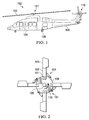
Figure 1 is a side view of a rotorcraft in helicopter mode, according to an example embodiment; -
Figure 2 is a top schematic view of a rotor hub, according to an example embodiment; -
Figure 3 is a top partial perspective view of a rotor hub, according to an example embodiment; -
Figure 4A is a top partial perspective view of a rotor hub, according to an example embodiment; -
Figure 4B is a top partial perspective view of a rotor hub, according to an example embodiment; -
Figure 5 is a perspective view of a rotor hub having a damper, according to an example embodiment; -
Figure 6 is a partial cutaway perspective view of the damper, according to an example embodiment; -
Figure 7 is a partial cutaway perspective view of the damper, according to an example embodiment; and -
Figure 8 is a partial cutaway perspective view of a damper, according to another example embodiment. - Illustrative embodiments of the apparatus are described below. In the interest of clarity, all features of an actual implementation may not be described in this specification. It will of course be appreciated that in the development of any such actual embodiment, numerous implementation-specific decisions must be made to achieve the developer's specific goals, such as compliance with system-related and business-related constraints, which will vary from one implementation to another. Moreover, it will be appreciated that such a development effort might be complex and time-consuming but would nevertheless be a routine undertaking for those of ordinary skill in the art having the benefit of this disclosure.
- In the specification, reference may be made to the spatial relationships between various components and to the spatial orientation of various aspects of components as the devices are depicted in the attached drawings. However, as will be recognized by those skilled in the art after a complete reading of the present application, the devices, members, apparatuses, etc. described herein may be positioned in any desired orientation. Thus, the use of terms such as "above," "below," "upper," "lower," or other like terms to describe a spatial relationship between various components or to describe the spatial orientation of aspects of such components should be understood to describe a relative relationship between the components or a spatial orientation of aspects of such components, respectively, as the device described herein may be oriented in any desired direction.
- Referring to
Figure 1 in the drawings, arotorcraft 102 is illustrated. Rotorcraft 102 has amain rotor system 101 with a plurality ofrotor blades 103. Rotorcraft 102 further includes afuselage 104,landing gear 106, and anempennage 108. A main rotor control system can be used to selectively control the pitch of eachrotor blade 103 in order to selectively control direction, thrust, and lift ofrotorcraft 101. Rotorcraft 102 can also include atail rotor system 110 for providing anti-torque and directional control. It should be appreciated that even though the present disclosure is depicted with regard to arotorcraft 102 having certain illustrated features, it should be appreciated that the embodiments disclosed herein can be implemented on other rotorcraft and rotorcraft configurations, as one of ordinary skill in the art would fully appreciate having the benefit of this disclosure. - Referring to
Figure 2 , arotor hub 101 ofrotorcraft 102 includes a plurality ofrotor blades 103 coupled to acentral yoke 109, via arotor grip 107. Yoke 109 is coupled to arotor mast 105 such that rotation ofrotor mast 105, in adirection 113, causes theyoke 109 androtor blades 103 to rotate about the rotor mast axis of rotation. Eachrotor blade 103 can be hinged about ahinge axis 111.Hinge axis 111 can be the result of a discreet hinge, or alternatively from a virtual hinge, or combination thereof. Adamper 501 is coupled between eachrotor blade 103 and therotor yoke 109. Damper 501 is configured to dampen lead/lag oscillations during operation of the rotorcraft, as further described herein. It should be appreciated that the even thoughrotor hub 101 is illustrated with fourrotor blades 103, the embodiments of the present disclosure are equally applicable to rotor hubs having an alternative number ofrotor blades 103. Further, it should be appreciated that even thoughdamper 501 particularly well suited for a main rotor hub, as illustrated,damper 501 may also be utilized on a tail rotor hub, such as in tail rotor system 110 (illustrated inFigure 1 ). - Referring now to
Figure 3 ,rotor hub 101 is further illustrated. For clarity, only asingle rotor blade 103 is shown; however, it should be appreciated that the disclosure regarding to therotor blade 103 is equally applicable toother rotor blades 103 that are not shown for clarity. During operation of the rotorcraft,rotor hub 101 is subjected to a variety of aerodynamic forces, as well as mechanical dynamic forces.Rotor hub 101 can rotate around the rotor mast axis at approximately 300-350 revolutions per minute (RPM). However, it should be appreciated that the rate of rotation ofrotor hub 101 is implementation specific; accordingly, the present disclosure contemplates rotor hubs that rotate at other RPM's as well. - A
centrifugal force 119 acts uponrotor blade 103 whenrotor blade 103 is rotating around the rotor mast axis. Further, anaerodynamic drag force 117 imparts a restraining force upon therotor blade 103. Thecentrifugal force 119 andaerodynamic drag force 117 create moments that act uponrotor blade 103. Thedamper 501 also creates a moment acting on therotor blade 103. When the moments from thecentrifugal force 119, thedamper 501 andaerodynamic drag force 117 are balanced, then therotor blade 103 is an equilibrium position, such asequilibrium position 115. However, when thecentrifugal force 119,damper force 501 andaerodynamic drag force 117 change during operation of the rotorcraft, then a relatively steady force acts onrotor blade 103 until the relatively steady force repositionsrotor blade 103 into a new equilibrium position. - Referring also to
Figure 4A ,rotor blade 103 is shown in a forward position 115' in which the position ofrotor blade 103 has deviated forwardly fromequilibrium position 115. Referring also toFigure 4B ,rotor blade 103 is shown in anaft position 115" in which the position ofrotor blade 103 has deviated aft ofequilibrium position 115. These deviations ofrotor blade 103 into a forward position 115' or anaft position 115", can be the result of a lead/lag force that imparts an oscillatory force causing the temporary positioning ofrotor blade 103 in forward position 115' oraft position 115". When airflow resulting from a translation of the rotorcraft, or a wind gust, aligns with a directional position ofrotor blade 103, then the temporary decrease in drag and additional damper force act to accelerate therotor blade 103 during that rotational phase of therotor blade 103, resulting in the temporary forward position 115'. In contrast, when the translation airflow direction opposes the directional position ofrotor blade 103, then the temporary increase in drag and additional damper force act to decelerate therotor blade 103 during that rotation phase of therotor blade 103, resulting in the temporaryaft position 115". These lead/lag forces act to accelerate and decelerate eachrotor blade 103 within a single revolution about therotor mast 105. It is highly desirable to efficiently and effectively treat the lead/lag forces, as well as other oscillatory forces, with a damper. - Referring now to
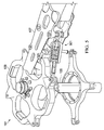
Figures 5-7 ,damper 501 is illustrated in further detail.Damper 501 can includehousing 503 rigidly coupled to a first attachment member 505.Damper 501 can also include asecond attachment member 507 rigidly coupled to apiston 509. In illustrated embodiment, first attachment member 505 andsecond attachment member 507 are coupled torotor grip 107 andyoke 109, respectively; however, it should be appreciated thatdamper 501 may be associated with therotor hub 101 in a variety of configurations. Furthermore,damper 501 may alternatively be coupled betweenadjacent rotor blades 103, instead of being coupled between eachrotor blade 103 andyoke 109. In the example embodiment, first andsecond attachment members 505 and 507 are rod ends each having an integral spherical bearing; however, it should be appreciated that first andsecond attachment members 505 and 507 may be of any configuration capable of providing a structural connection betweenrotor blade 103 androtor yoke 109. -
Housing 503 includes a hollow interior to which the operative components ofdamper 501 reside.Piston 509 extends along acentral axis 511 within the hollow interior ofhousing 503.Piston 509 is resiliently coupled to an interior ofhousing 503 with a firstelastomeric member 513 and a secondelastomeric member 515. Firstelastomeric member 513 and secondelastomeric member 515 include elastomeric material that has an implementation spring rate and damping rate. It should be appreciated thatelastomeric members damper 501. In one example embodiment,elastomeric members elastomeric members elastomeric members elastomeric members damper 501, as discussed further herein. -
Damper 501 also includes a plurality ofconical members 517a-517j that are preferably metallic and deflect under a load along thecentral axis 511. Theconical members 517a-517j have an implementation specific spring rate that can be dependent upon the material, size, geometry, and quantity thereof. The total spring rate ofdamper 501 is the combination ofconical members 517a-517j andelastomeric members conical members 517a-517j doesn't vary at extreme temperatures as much as elastomeric material, thus the total spring rate doesn't vary as much as if the total spring rate was derived solely from elastomeric material. -
Piston 509 has an elongatedportion 521 that extends through an interior opening of eachconical member 517a-517j. Asleeve 523 can be utilized adjacent to an interior ofhousing 503. In an alternative embodiment,sleeve 523 is integral withhousing 503. A sealed fluid housing is formed bysleeve 523, firstelastomeric member 513, secondelastomeric member 515, andpiston 509. The fluid housing is filled with a fluid 525 that is viscous and has the implementation specific viscosity characteristics to provide the desired damping. It should be appreciated a fluid accumulator, volume compensator, or the like, can be plumbed to fluid housing in order to maintain a desired pressure offluid 525 within the fluid housing. - During operation,
conical members 517a-517j not only provide spring rate during deflection, but also act to force fluid 525 back and forth through one or more orifices to provide damping aspiston 521 oscillates alongcentral axis 511 relative tohousing 503. For example, orifices can beinner channels 526a-526d formed by the annular clearance between the inner portions ofconical member elongated portion 521 ofpiston 509.Inner channels 526a-526d provide a damping fluid path between theinner chambers 527a-527e formed by adjacent oppositely orientedconical members 517a-517j. Further, orifices can be alsoouter channels 529a-529d that are formed by the annular clearance between the outer portions ofconical members 517a-517d and 517f-517g-517j and the inner surface ofsleeve 523 to provide a damping fluid path betweenouter chambers 528a-528c, as well asouter chambers 528d-528e. Afluid path 543 can be utilized to provide fluid communication betweenouter chambers inner channels 526a-526d,outer channels 529a-529d, andfluid path 543 are merely exemplary of a variety orifices that can be implemented betweenconical members 517a-517j to generate damping. - In the example embodiment, adjacent conical members are oriented oppositely to each other. An inner portion of
conical member 517a abuts to ashoulder 531 ofpiston 509 while an outer portion abuts to an outer portion ofconical member 517b. An inner portion ofconical member 517b abuts to an inner portion ofconical member 517c. An outer portion ofconical member 517c abuts to an outer portion ofconical member 517d. An inner portion ofconical member 517d abuts to an inner portion ofconical member 517e. An outer portion ofconical member 517e abuts to ashoulder 533 onsleeve 523.Conical members 517f-517j are oriented in a similar but opposition orientation to that ofconical members 517a-517e. The outer portion ofconical member 517f abuts to ashoulder 535 onsleeve 523. An inner portion ofconical member 517j abuts to ashoulder 537 onpiston 509. Fluid seals can be utilized between inner portion ofconical member 517a andshoulder 531, between outer portion ofconical member 517e andsleeve 523, between outer portion ofconical member 517f andsleeve 523, and between inner portion ofconical member 528f andshoulder 537. - During operation,
piston 509 can oscillate relative tohousing 503. One oscillatory component can be a translation ofpiston 509 indirection 539 relative tohousing 503. Such a movement ofpiston 509 indirection 539 causesconical members 517f-517j to compress together resulting in a countering spring force,conical members 517a-517e to expand, and damping byfluid 525 being forced through any orifices betweenchambers 527a-527e andchambers 528a-528f. Similarly, the opposite oscillatory component can be a translation ofpiston 509 indirection 541 relative to housing. Such a movement ofpiston 509 indirection 541 causesconical members 517a-517e to compress together resulting in a countering spring force,conical members 517f-517j to expand, and damping byfluid 525 being forced through any orifices betweenchambers 527a-527e andchambers 528a-528f.Conical members 517a-517j are installed intodamper 501 in pre-compression so thatconical members 517a-517j remain in compression during operation. - One unique feature of the example embodiment is that
inner chambers 527a-527e are fluidly connected together withinner channels 526a-526d to produce a primary damping rate as fluid is forced throughinner channels 526a-526d at relatively high pressure. Theouter chambers 528a-528f are fluidly connected together withouter channels 529a-529d andfluid path 543 to produce a secondary damping rate as fluid is forced throughouter channels 529a-529d andfluid path 543 at a relatively low pressure. In the illustrated embodiment,inner chambers 527a-527e are pressurized withfluid 525 at a higher pressure than the pressurization offluid 525 inouter chambers 528a-528f, thus thedamper 501 can have desired damping characteristics at two different frequencies, which can be desirable in a rotor system, such arotor system 101, that can have two different operational frequencies that need damping. Such a configuration can be particularly desirable for rotorcraft that fly in a multitude of flight regimes, such as variable rotor speed rotorcraft or tiltrotor aircraft, for example. - Another benefit of having
inner chambers 527a-527e at high pressure andouter chambers 528a-528f at low pressure is that firstelastomeric member 513 and secondelastomeric member 515 are shielded from the high pressure environment which could otherwise have a negative impact on the life and reliability of firstelastomeric member 513 and secondelastomeric member 515. - In the example embodiment, if any of the fluid seals between inner portion of
conical member 517a andshoulder 531, between outer portion ofconical member 517e andsleeve 523, between outer portion ofconical member 517f andsleeve 523, and between inner portion ofconical member 528f andshoulder 537 were to fail, then the failsafe condition would be the equalization of the pressures ininner chambers 527a-527e withouter chambers 528a-528f such that thedamper 501 continues to provide damping. - Referring now also to
Figure 8 , analternative embodiment damper 801 is illustrated.Damper 801 is substantially similar todamper 501, except for the features noted herein.Damper 801 includes additionalfluid passages 803a-803d and 805 that fluidly connect theinner chambers 527a-527e andouter chambers 528a-528f. In one embodiment, thedamper 501 basically has a single damping rate. In another embodiment, certain orifices orfluid passages 803a-803d, and 805 can be configured to hydrolock at certain frequencies or pressures, thus creating a multiple damping rates. -
Dampers - The particular embodiments disclosed above are illustrative only, as the apparatus may be modified and practiced in different but equivalent manners apparent to those skilled in the art having the benefit of the teachings herein. Modifications, additions, or omissions may be made to the apparatuses described herein without departing from the scope of the invention. The components of the apparatus may be integrated or separated. Moreover, the operations of the apparatus may be performed by more, fewer, or other components.
- Furthermore, no limitations are intended to the details of construction or design herein shown, other than as described in the claims below. It is therefore evident that the particular embodiments disclosed above may be altered or modified and all such variations are considered within the scope of the application. Accordingly, the protection sought herein is as set forth in the claims below.
Claims (15)
- A damper (501; 801) for a rotor hub (101, 110) for a rotorcraft (102), the damper comprising:a housing (503) having a hollow interior;a plurality of conical members (517a-517j) disposed within the hollow interior of the housing arranged to deflect under a load along the central axis (511) of the housing (503);a piston (509) resiliently coupled to the housing (503) with a first elastomeric member (513) and a second elastomeric member (515) wherein the piston (509) has an elongated portion (521) that extends through an opening in each of the plurality of conical members (517a-517j);a fluid (525) within the housing (503);an orifice (526a-526d, 529a-529d; 803a-803d, 805) configured so that oscillation of the piston (509) within the housing (503) causes the conical members (517a-517j) to force the fluid (528) through the orifice (526a-526d, 529a-529d); 803a-803d, 805).
- The damper according to claim 1, wherein the first elastomeric member (513), the second elastomeric member (515), the piston (509), and the housing (503) form inner chambers and outer chambers for the fluid (525).
- The damper according to claim 1 or claim 2, wherein the plurality of conical members (517a-517j) are stacked in an alternating arrangement.
- The damper according to claim 1 or claim 2 or claim 3, wherein the plurality of conical members include a first conical member (517a) having an inner portion abutted to a shoulder (531) of the piston (509), and optionally or preferably further comprising:a seal between the inner portion of the first conical member (517a) and the shoulder (531) of the piston (509).
- The damper according to claim 1 or any of claims 2 to 4, wherein the plurality of conical members include a second conical member (517, 517f) having an outer portion abutted to a shoulder (535) of the housing, and optionally or preferably further comprising:a seal between the outer portion of the second conical (517e, 517f) member and the shoulder of the housing.
- The damper according to claim 1 or any preceding claim, wherein the damper has a spring rate derived from the first elastomeric member (513), the second elastomeric member (515), and the plurality of conical members (517a-517j).
- The damper according to claim 1 or any preceding claim, wherein the damper has a damping rate derived from at least the fluid being forced through the orifice during a translation of the piston (509) relative to the housing (503).
- The damper according to claim 1 or any preceding claim, wherein the plurality of conical members (517a-517j) are metal.
- The damper according to claim 1 or any preceding claim, wherein the rotor hub is a main rotor hub (101) or wherein the rotor hub is a tail rotor hub (110).
- A system comprising a grip of a rotor blade and the damper of any preceding claim, wherein the housing (503) is configured to be coupled to a rotor grip (107) of a rotor blade (103).
- A system comprising a yoke (109) of a rotor hub and the damper according to any one of claims 1 to 9, wherein the piston (509) is coupled to the yoke (109) of the rotor hub (101; 110).
- The system. according to claim 11, wherein the orifice is an inner channel formed by a clearance between an inner portion of at least one of the plurality of conical members (517a-517j) and the elongated portion of the piston (509).
- The damper according to claim 1 or any of claims 2 to 9 or the system according to claims 10 to 12, wherein the orifice is an outer channel formed by a clearance between an outer portion of at least one of the plurality of conical members (517a-517j) and the housing (503).
- The damper according to claim 2 or any of claims 3 to 9 or 13 dependent directly or indirectly from claim 2 or the system of claims 10 to 13 dependent directly or indirectly from claim 2, wherein the inner chambers have a higher pressure of fluid than the outer chambers.
- The damper according to claim 2 or any of claims 3 to 9, 13 or 14 dependent directly or indirectly from claim 2 or the system of claims 10 to 14 dependent directly or indirectly from claim 2, wherein the orifice includes a plurality of inner channels fluidly connecting the inner chambers, and include a plurality of outer channels fluidly connecting the outer chambers, and optionally or preferably further comprising:a plurality of fluid passages providing fluid communication between the outer chambers and the inner chambers.
Applications Claiming Priority (1)
| Application Number | Priority Date | Filing Date | Title |
|---|---|---|---|
| US14/135,670 US9765825B2 (en) | 2013-12-20 | 2013-12-20 | Rotor hub damper for a rotorcraft |
Publications (2)
| Publication Number | Publication Date |
|---|---|
| EP2886457A1 EP2886457A1 (en) | 2015-06-24 |
| EP2886457B1 true EP2886457B1 (en) | 2016-02-03 |
Family
ID=51162612
Family Applications (1)
| Application Number | Title | Priority Date | Filing Date |
|---|---|---|---|
| EP14176755.8A Active EP2886457B1 (en) | 2013-12-20 | 2014-07-11 | Rotor hub damper for a rotorcraft |
Country Status (3)
| Country | Link |
|---|---|
| US (1) | US9765825B2 (en) |
| EP (1) | EP2886457B1 (en) |
| CA (1) | CA2863707C (en) |
Families Citing this family (6)
| Publication number | Priority date | Publication date | Assignee | Title |
|---|---|---|---|---|
| FR3053312B1 (en) * | 2016-06-29 | 2019-07-19 | Airbus Helicopters | ROTOR AND AIRCRAFT PROVIDED WITH SUCH A ROTOR |
| EP3543557B1 (en) * | 2018-03-22 | 2023-12-20 | Goodrich Actuation Systems Limited | Disc spring assembly |
| EP3755623A1 (en) * | 2018-05-08 | 2020-12-30 | AVX Aircraft Company | Rotor hub |
| US11554864B2 (en) * | 2020-03-27 | 2023-01-17 | Textron Innoations Inc. | Techniques for increasing heat dissipation in lead-lag dampers |
| US11697492B2 (en) | 2020-04-09 | 2023-07-11 | Roller Bearing Company Of America, Inc. | Rotor blade lead-lag hydraulic damper with centrifugal force compensating damping characteristics |
| CN111927915B (en) * | 2020-07-03 | 2021-08-24 | 中国船舶重工集团公司第七0四研究所 | Damping buffer for laying and recovering operation of submersible |
Family Cites Families (21)
| Publication number | Priority date | Publication date | Assignee | Title |
|---|---|---|---|---|
| US3409285A (en) * | 1965-07-12 | 1968-11-05 | Rheinstahl Henschel Ag | Shock absorber assembly |
| US3345019A (en) * | 1965-12-30 | 1967-10-03 | Bendix Corp | Aircraft landing gear |
| FR2629163B1 (en) * | 1988-03-24 | 1991-01-04 | Aerospatiale | ELASTO-HYDRAULIC TYPE ELASTIC RECALL SHEET WITH LINEAR DAMPING INCORPORATED BY LAMINATION OF A HIGH VISCOSITY FLUID |
| US5501434A (en) * | 1994-05-10 | 1996-03-26 | Lord Corporation | Hybrid fluid and elastomer damper |
| JPH08121528A (en) | 1994-10-26 | 1996-05-14 | Tokai Rubber Ind Ltd | Liquid sealed suspension bush |
| US6092795A (en) * | 1997-08-04 | 2000-07-25 | Lord Corporation | Fluid and elastomer damper |
| GB0126978D0 (en) | 2001-11-09 | 2002-01-02 | Avon Vibration Man Syst Ltd | Hydraulically damped mountain device |
| FR2835506B1 (en) * | 2002-02-06 | 2004-03-12 | Eurocopter France | DOUBLE PISTON TRAIN SHOCK ABSORBER FOR ROTOR OF ROTOR |
| DE102007020137A1 (en) | 2007-04-28 | 2008-05-29 | Daimler Ag | Hydraulic motor vehicle chassis bearing has an elastomer body with inner and outer bushes and a hollow body, within the fluid-filled hollow zone, linked to it through a throttled opening |
| FR2928344B1 (en) | 2008-03-06 | 2011-01-21 | Hutchinson | DAMPING DEVICE AND AERODYNE ROTOR SYSTEM INCORPORATING IT |
| WO2010030340A2 (en) * | 2008-09-09 | 2010-03-18 | Hodgson Darel E | Apparatus for absorbing shock |
| WO2010062937A1 (en) * | 2008-11-26 | 2010-06-03 | Lord Corporation | Fluid elastomeric damper assembly including internal pumping mechanism and volume compensator |
| EP2424778A1 (en) * | 2009-04-28 | 2012-03-07 | Lord Corporation | Fluid elastomeric damper assembly |
| WO2010141628A2 (en) * | 2009-06-02 | 2010-12-09 | Dunn Marcus L | Helicopter landing gear damper |
| FR2949432B1 (en) * | 2009-08-25 | 2011-10-14 | Eurocopter France | FREQUENCY ADAPTER AND RECOVERY DEVICE SUITABLE FOR AGENCY IN SUCH FREQUENCY ADAPTER |
| EP2601099B1 (en) * | 2010-08-05 | 2018-07-04 | LORD Corporation | Fluid elastomeric damper assembly including internal pumping mechanism and control valve |
| FR2965850B1 (en) * | 2010-10-11 | 2012-12-14 | Airbus Operations Sas | SAFETY LINK DEVICE AND AIRCRAFT EQUIPPED WITH SUCH A SAFETY LINK DEVICE |
| KR20130130009A (en) * | 2010-12-03 | 2013-11-29 | 로오드 코포레이션 | Frequency-dependent damper and rotary wing system |
| WO2012115645A1 (en) * | 2011-02-24 | 2012-08-30 | Bell Helicopter Textron Inc. | A temperature adaptive fluid damping system |
| US8622375B2 (en) | 2012-03-16 | 2014-01-07 | Textron Innovations Inc. | Dual frequency damper for an aircraft |
| US9353820B2 (en) * | 2013-04-11 | 2016-05-31 | Bell Helicopter Textron Inc. | Elastomeric damper with heater |
-
2013
- 2013-12-20 US US14/135,670 patent/US9765825B2/en active Active
-
2014
- 2014-07-11 EP EP14176755.8A patent/EP2886457B1/en active Active
- 2014-09-16 CA CA2863707A patent/CA2863707C/en active Active
Also Published As
| Publication number | Publication date |
|---|---|
| EP2886457A1 (en) | 2015-06-24 |
| CA2863707A1 (en) | 2015-06-20 |
| US20150176658A1 (en) | 2015-06-25 |
| CA2863707C (en) | 2019-01-08 |
| US9765825B2 (en) | 2017-09-19 |
Similar Documents
| Publication | Publication Date | Title |
|---|---|---|
| EP2886457B1 (en) | Rotor hub damper for a rotorcraft | |
| EP2678222B1 (en) | Dual series damper system | |
| US7828525B2 (en) | Soft in-plane tiltrotor hub | |
| EP2665945B1 (en) | A temperature adaptive fluid damping system | |
| CA2805894C (en) | Dual frequency damper for an aircraft | |
| EP2223854B1 (en) | Helicopter rotor | |
| US6926500B2 (en) | Fluid inertia drag damper for rotary wing aircraft rotor | |
| US8764396B2 (en) | Lead-lag damper for rotor hubs | |
| US8177202B2 (en) | Damping device and aircraft rotor system incorporating it | |
| US20030146343A1 (en) | Dual piston drag damper for rotary-wing aircraft rotor | |
| US9481454B2 (en) | Linking damper system for a rotorcraft landing gear | |
| EP0135296B1 (en) | Helicopter rotors | |
| US20130034442A1 (en) | Lead lag damper for helicopter rotor unit | |
| US20190127054A1 (en) | Compact Design of a Liquid Inertia Vibration Elimination System |
Legal Events
| Date | Code | Title | Description |
|---|---|---|---|
| PUAI | Public reference made under article 153(3) epc to a published international application that has entered the european phase |
Free format text: ORIGINAL CODE: 0009012 |
|
| 17P | Request for examination filed |
Effective date: 20140711 |
|
| AK | Designated contracting states |
Kind code of ref document: A1 Designated state(s): AL AT BE BG CH CY CZ DE DK EE ES FI FR GB GR HR HU IE IS IT LI LT LU LV MC MK MT NL NO PL PT RO RS SE SI SK SM TR |
|
| AX | Request for extension of the european patent |
Extension state: BA ME |
|
| RIC1 | Information provided on ipc code assigned before grant |
Ipc: F16F 13/14 20060101ALI20150915BHEP Ipc: B64C 27/51 20060101AFI20150915BHEP Ipc: F16F 1/32 20060101ALI20150915BHEP |
|
| GRAP | Despatch of communication of intention to grant a patent |
Free format text: ORIGINAL CODE: EPIDOSNIGR1 |
|
| GRAS | Grant fee paid |
Free format text: ORIGINAL CODE: EPIDOSNIGR3 |
|
| INTG | Intention to grant announced |
Effective date: 20151106 |
|
| GRAA | (expected) grant |
Free format text: ORIGINAL CODE: 0009210 |
|
| AK | Designated contracting states |
Kind code of ref document: B1 Designated state(s): AL AT BE BG CH CY CZ DE DK EE ES FI FR GB GR HR HU IE IS IT LI LT LU LV MC MK MT NL NO PL PT RO RS SE SI SK SM TR |
|
| REG | Reference to a national code |
Ref country code: GB Ref legal event code: FG4D |
|
| REG | Reference to a national code |
Ref country code: AT Ref legal event code: REF Ref document number: 773552 Country of ref document: AT Kind code of ref document: T Effective date: 20160215 Ref country code: CH Ref legal event code: EP |
|
| REG | Reference to a national code |
Ref country code: IE Ref legal event code: FG4D |
|
| REG | Reference to a national code |
Ref country code: DE Ref legal event code: R096 Ref document number: 602014000841 Country of ref document: DE |
|
| REG | Reference to a national code |
Ref country code: LT Ref legal event code: MG4D Ref country code: NL Ref legal event code: MP Effective date: 20160203 |
|
| REG | Reference to a national code |
Ref country code: AT Ref legal event code: MK05 Ref document number: 773552 Country of ref document: AT Kind code of ref document: T Effective date: 20160203 |
|
| REG | Reference to a national code |
Ref country code: FR Ref legal event code: PLFP Year of fee payment: 3 |
|
| PG25 | Lapsed in a contracting state [announced via postgrant information from national office to epo] |
Ref country code: ES Free format text: LAPSE BECAUSE OF FAILURE TO SUBMIT A TRANSLATION OF THE DESCRIPTION OR TO PAY THE FEE WITHIN THE PRESCRIBED TIME-LIMIT Effective date: 20160203 Ref country code: FI Free format text: LAPSE BECAUSE OF FAILURE TO SUBMIT A TRANSLATION OF THE DESCRIPTION OR TO PAY THE FEE WITHIN THE PRESCRIBED TIME-LIMIT Effective date: 20160203 Ref country code: GR Free format text: LAPSE BECAUSE OF FAILURE TO SUBMIT A TRANSLATION OF THE DESCRIPTION OR TO PAY THE FEE WITHIN THE PRESCRIBED TIME-LIMIT Effective date: 20160504 Ref country code: NO Free format text: LAPSE BECAUSE OF FAILURE TO SUBMIT A TRANSLATION OF THE DESCRIPTION OR TO PAY THE FEE WITHIN THE PRESCRIBED TIME-LIMIT Effective date: 20160503 Ref country code: HR Free format text: LAPSE BECAUSE OF FAILURE TO SUBMIT A TRANSLATION OF THE DESCRIPTION OR TO PAY THE FEE WITHIN THE PRESCRIBED TIME-LIMIT Effective date: 20160203 |
|
| PG25 | Lapsed in a contracting state [announced via postgrant information from national office to epo] |
Ref country code: SE Free format text: LAPSE BECAUSE OF FAILURE TO SUBMIT A TRANSLATION OF THE DESCRIPTION OR TO PAY THE FEE WITHIN THE PRESCRIBED TIME-LIMIT Effective date: 20160203 Ref country code: IS Free format text: LAPSE BECAUSE OF FAILURE TO SUBMIT A TRANSLATION OF THE DESCRIPTION OR TO PAY THE FEE WITHIN THE PRESCRIBED TIME-LIMIT Effective date: 20160603 Ref country code: LT Free format text: LAPSE BECAUSE OF FAILURE TO SUBMIT A TRANSLATION OF THE DESCRIPTION OR TO PAY THE FEE WITHIN THE PRESCRIBED TIME-LIMIT Effective date: 20160203 Ref country code: NL Free format text: LAPSE BECAUSE OF FAILURE TO SUBMIT A TRANSLATION OF THE DESCRIPTION OR TO PAY THE FEE WITHIN THE PRESCRIBED TIME-LIMIT Effective date: 20160203 Ref country code: PL Free format text: LAPSE BECAUSE OF FAILURE TO SUBMIT A TRANSLATION OF THE DESCRIPTION OR TO PAY THE FEE WITHIN THE PRESCRIBED TIME-LIMIT Effective date: 20160203 Ref country code: RS Free format text: LAPSE BECAUSE OF FAILURE TO SUBMIT A TRANSLATION OF THE DESCRIPTION OR TO PAY THE FEE WITHIN THE PRESCRIBED TIME-LIMIT Effective date: 20160203 Ref country code: LV Free format text: LAPSE BECAUSE OF FAILURE TO SUBMIT A TRANSLATION OF THE DESCRIPTION OR TO PAY THE FEE WITHIN THE PRESCRIBED TIME-LIMIT Effective date: 20160203 Ref country code: PT Free format text: LAPSE BECAUSE OF FAILURE TO SUBMIT A TRANSLATION OF THE DESCRIPTION OR TO PAY THE FEE WITHIN THE PRESCRIBED TIME-LIMIT Effective date: 20160603 Ref country code: AT Free format text: LAPSE BECAUSE OF FAILURE TO SUBMIT A TRANSLATION OF THE DESCRIPTION OR TO PAY THE FEE WITHIN THE PRESCRIBED TIME-LIMIT Effective date: 20160203 |
|
| PG25 | Lapsed in a contracting state [announced via postgrant information from national office to epo] |
Ref country code: DK Free format text: LAPSE BECAUSE OF FAILURE TO SUBMIT A TRANSLATION OF THE DESCRIPTION OR TO PAY THE FEE WITHIN THE PRESCRIBED TIME-LIMIT Effective date: 20160203 Ref country code: EE Free format text: LAPSE BECAUSE OF FAILURE TO SUBMIT A TRANSLATION OF THE DESCRIPTION OR TO PAY THE FEE WITHIN THE PRESCRIBED TIME-LIMIT Effective date: 20160203 |
|
| REG | Reference to a national code |
Ref country code: DE Ref legal event code: R097 Ref document number: 602014000841 Country of ref document: DE |
|
| PG25 | Lapsed in a contracting state [announced via postgrant information from national office to epo] |
Ref country code: RO Free format text: LAPSE BECAUSE OF FAILURE TO SUBMIT A TRANSLATION OF THE DESCRIPTION OR TO PAY THE FEE WITHIN THE PRESCRIBED TIME-LIMIT Effective date: 20160203 Ref country code: CZ Free format text: LAPSE BECAUSE OF FAILURE TO SUBMIT A TRANSLATION OF THE DESCRIPTION OR TO PAY THE FEE WITHIN THE PRESCRIBED TIME-LIMIT Effective date: 20160203 Ref country code: SK Free format text: LAPSE BECAUSE OF FAILURE TO SUBMIT A TRANSLATION OF THE DESCRIPTION OR TO PAY THE FEE WITHIN THE PRESCRIBED TIME-LIMIT Effective date: 20160203 Ref country code: SM Free format text: LAPSE BECAUSE OF FAILURE TO SUBMIT A TRANSLATION OF THE DESCRIPTION OR TO PAY THE FEE WITHIN THE PRESCRIBED TIME-LIMIT Effective date: 20160203 |
|
| PLBE | No opposition filed within time limit |
Free format text: ORIGINAL CODE: 0009261 |
|
| STAA | Information on the status of an ep patent application or granted ep patent |
Free format text: STATUS: NO OPPOSITION FILED WITHIN TIME LIMIT |
|
| PG25 | Lapsed in a contracting state [announced via postgrant information from national office to epo] |
Ref country code: BE Free format text: LAPSE BECAUSE OF FAILURE TO SUBMIT A TRANSLATION OF THE DESCRIPTION OR TO PAY THE FEE WITHIN THE PRESCRIBED TIME-LIMIT Effective date: 20160203 |
|
| 26N | No opposition filed |
Effective date: 20161104 |
|
| PG25 | Lapsed in a contracting state [announced via postgrant information from national office to epo] |
Ref country code: SI Free format text: LAPSE BECAUSE OF FAILURE TO SUBMIT A TRANSLATION OF THE DESCRIPTION OR TO PAY THE FEE WITHIN THE PRESCRIBED TIME-LIMIT Effective date: 20160203 Ref country code: BG Free format text: LAPSE BECAUSE OF FAILURE TO SUBMIT A TRANSLATION OF THE DESCRIPTION OR TO PAY THE FEE WITHIN THE PRESCRIBED TIME-LIMIT Effective date: 20160503 |
|
| PG25 | Lapsed in a contracting state [announced via postgrant information from national office to epo] |
Ref country code: MC Free format text: LAPSE BECAUSE OF FAILURE TO SUBMIT A TRANSLATION OF THE DESCRIPTION OR TO PAY THE FEE WITHIN THE PRESCRIBED TIME-LIMIT Effective date: 20160203 |
|
| REG | Reference to a national code |
Ref country code: IE Ref legal event code: MM4A |
|
| REG | Reference to a national code |
Ref country code: FR Ref legal event code: PLFP Year of fee payment: 4 |
|
| PG25 | Lapsed in a contracting state [announced via postgrant information from national office to epo] |
Ref country code: IE Free format text: LAPSE BECAUSE OF NON-PAYMENT OF DUE FEES Effective date: 20160711 |
|
| PG25 | Lapsed in a contracting state [announced via postgrant information from national office to epo] |
Ref country code: LU Free format text: LAPSE BECAUSE OF NON-PAYMENT OF DUE FEES Effective date: 20160711 |
|
| REG | Reference to a national code |
Ref country code: CH Ref legal event code: PL |
|
| PG25 | Lapsed in a contracting state [announced via postgrant information from national office to epo] |
Ref country code: LI Free format text: LAPSE BECAUSE OF NON-PAYMENT OF DUE FEES Effective date: 20170731 Ref country code: CH Free format text: LAPSE BECAUSE OF NON-PAYMENT OF DUE FEES Effective date: 20170731 |
|
| PG25 | Lapsed in a contracting state [announced via postgrant information from national office to epo] |
Ref country code: HU Free format text: LAPSE BECAUSE OF FAILURE TO SUBMIT A TRANSLATION OF THE DESCRIPTION OR TO PAY THE FEE WITHIN THE PRESCRIBED TIME-LIMIT; INVALID AB INITIO Effective date: 20140711 |
|
| PG25 | Lapsed in a contracting state [announced via postgrant information from national office to epo] |
Ref country code: CY Free format text: LAPSE BECAUSE OF FAILURE TO SUBMIT A TRANSLATION OF THE DESCRIPTION OR TO PAY THE FEE WITHIN THE PRESCRIBED TIME-LIMIT Effective date: 20160203 Ref country code: MK Free format text: LAPSE BECAUSE OF FAILURE TO SUBMIT A TRANSLATION OF THE DESCRIPTION OR TO PAY THE FEE WITHIN THE PRESCRIBED TIME-LIMIT Effective date: 20160203 Ref country code: MT Free format text: LAPSE BECAUSE OF NON-PAYMENT OF DUE FEES Effective date: 20160731 |
|
| REG | Reference to a national code |
Ref country code: FR Ref legal event code: PLFP Year of fee payment: 5 |
|
| PG25 | Lapsed in a contracting state [announced via postgrant information from national office to epo] |
Ref country code: TR Free format text: LAPSE BECAUSE OF FAILURE TO SUBMIT A TRANSLATION OF THE DESCRIPTION OR TO PAY THE FEE WITHIN THE PRESCRIBED TIME-LIMIT Effective date: 20160203 Ref country code: AL Free format text: LAPSE BECAUSE OF FAILURE TO SUBMIT A TRANSLATION OF THE DESCRIPTION OR TO PAY THE FEE WITHIN THE PRESCRIBED TIME-LIMIT Effective date: 20160203 |
|
| PGFP | Annual fee paid to national office [announced via postgrant information from national office to epo] |
Ref country code: IT Payment date: 20210721 Year of fee payment: 8 |
|
| PGFP | Annual fee paid to national office [announced via postgrant information from national office to epo] |
Ref country code: GB Payment date: 20210727 Year of fee payment: 8 |
|
| GBPC | Gb: european patent ceased through non-payment of renewal fee |
Effective date: 20220711 |
|
| PG25 | Lapsed in a contracting state [announced via postgrant information from national office to epo] |
Ref country code: GB Free format text: LAPSE BECAUSE OF NON-PAYMENT OF DUE FEES Effective date: 20220711 |
|
| P01 | Opt-out of the competence of the unified patent court (upc) registered |
Effective date: 20230602 |
|
| PG25 | Lapsed in a contracting state [announced via postgrant information from national office to epo] |
Ref country code: IT Free format text: LAPSE BECAUSE OF NON-PAYMENT OF DUE FEES Effective date: 20220711 |
|
| PGFP | Annual fee paid to national office [announced via postgrant information from national office to epo] |
Ref country code: FR Payment date: 20230725 Year of fee payment: 10 Ref country code: DE Payment date: 20230727 Year of fee payment: 10 |