EP2883818A1 - System and method for orienting objects - Google Patents
System and method for orienting objects Download PDFInfo
- Publication number
- EP2883818A1 EP2883818A1 EP14190992.9A EP14190992A EP2883818A1 EP 2883818 A1 EP2883818 A1 EP 2883818A1 EP 14190992 A EP14190992 A EP 14190992A EP 2883818 A1 EP2883818 A1 EP 2883818A1
- Authority
- EP
- European Patent Office
- Prior art keywords
- objects
- orientation
- support surface
- path
- alveoli
- Prior art date
- Legal status (The legal status is an assumption and is not a legal conclusion. Google has not performed a legal analysis and makes no representation as to the accuracy of the status listed.)
- Granted
Links
- 238000000034 method Methods 0.000 title claims description 10
- 238000001514 detection method Methods 0.000 claims description 8
- 230000001174 ascending effect Effects 0.000 claims description 5
- 230000005484 gravity Effects 0.000 claims description 4
- 230000003287 optical effect Effects 0.000 claims description 4
- 230000002093 peripheral effect Effects 0.000 claims description 3
- 230000000694 effects Effects 0.000 description 3
- 210000003456 pulmonary alveoli Anatomy 0.000 description 3
- 238000003780 insertion Methods 0.000 description 2
- 230000037431 insertion Effects 0.000 description 2
- 238000011144 upstream manufacturing Methods 0.000 description 2
- 230000002411 adverse Effects 0.000 description 1
- 235000013361 beverage Nutrition 0.000 description 1
- 238000007664 blowing Methods 0.000 description 1
- 230000001419 dependent effect Effects 0.000 description 1
- -1 e.g. Substances 0.000 description 1
- 239000002783 friction material Substances 0.000 description 1
Images


Classifications
-
- B—PERFORMING OPERATIONS; TRANSPORTING
- B65—CONVEYING; PACKING; STORING; HANDLING THIN OR FILAMENTARY MATERIAL
- B65G—TRANSPORT OR STORAGE DEVICES, e.g. CONVEYORS FOR LOADING OR TIPPING, SHOP CONVEYOR SYSTEMS OR PNEUMATIC TUBE CONVEYORS
- B65G29/00—Rotary conveyors, e.g. rotating discs, arms, star-wheels or cones
-
- B—PERFORMING OPERATIONS; TRANSPORTING
- B65—CONVEYING; PACKING; STORING; HANDLING THIN OR FILAMENTARY MATERIAL
- B65G—TRANSPORT OR STORAGE DEVICES, e.g. CONVEYORS FOR LOADING OR TIPPING, SHOP CONVEYOR SYSTEMS OR PNEUMATIC TUBE CONVEYORS
- B65G47/00—Article or material-handling devices associated with conveyors; Methods employing such devices
- B65G47/02—Devices for feeding articles or materials to conveyors
- B65G47/04—Devices for feeding articles or materials to conveyors for feeding articles
- B65G47/12—Devices for feeding articles or materials to conveyors for feeding articles from disorderly-arranged article piles or from loose assemblages of articles
- B65G47/14—Devices for feeding articles or materials to conveyors for feeding articles from disorderly-arranged article piles or from loose assemblages of articles arranging or orientating the articles by mechanical or pneumatic means during feeding
- B65G47/1407—Devices for feeding articles or materials to conveyors for feeding articles from disorderly-arranged article piles or from loose assemblages of articles arranging or orientating the articles by mechanical or pneumatic means during feeding the articles being fed from a container, e.g. a bowl
- B65G47/1414—Devices for feeding articles or materials to conveyors for feeding articles from disorderly-arranged article piles or from loose assemblages of articles arranging or orientating the articles by mechanical or pneumatic means during feeding the articles being fed from a container, e.g. a bowl by means of movement of at least the whole wall of the container
- B65G47/1428—Devices for feeding articles or materials to conveyors for feeding articles from disorderly-arranged article piles or from loose assemblages of articles arranging or orientating the articles by mechanical or pneumatic means during feeding the articles being fed from a container, e.g. a bowl by means of movement of at least the whole wall of the container rotating movement
- B65G47/1435—Devices for feeding articles or materials to conveyors for feeding articles from disorderly-arranged article piles or from loose assemblages of articles arranging or orientating the articles by mechanical or pneumatic means during feeding the articles being fed from a container, e.g. a bowl by means of movement of at least the whole wall of the container rotating movement using the centrifugal effect to arrange or orientate the articles
-
- B—PERFORMING OPERATIONS; TRANSPORTING
- B65—CONVEYING; PACKING; STORING; HANDLING THIN OR FILAMENTARY MATERIAL
- B65G—TRANSPORT OR STORAGE DEVICES, e.g. CONVEYORS FOR LOADING OR TIPPING, SHOP CONVEYOR SYSTEMS OR PNEUMATIC TUBE CONVEYORS
- B65G47/00—Article or material-handling devices associated with conveyors; Methods employing such devices
- B65G47/02—Devices for feeding articles or materials to conveyors
- B65G47/04—Devices for feeding articles or materials to conveyors for feeding articles
- B65G47/12—Devices for feeding articles or materials to conveyors for feeding articles from disorderly-arranged article piles or from loose assemblages of articles
- B65G47/14—Devices for feeding articles or materials to conveyors for feeding articles from disorderly-arranged article piles or from loose assemblages of articles arranging or orientating the articles by mechanical or pneumatic means during feeding
- B65G47/1407—Devices for feeding articles or materials to conveyors for feeding articles from disorderly-arranged article piles or from loose assemblages of articles arranging or orientating the articles by mechanical or pneumatic means during feeding the articles being fed from a container, e.g. a bowl
- B65G47/1442—Devices for feeding articles or materials to conveyors for feeding articles from disorderly-arranged article piles or from loose assemblages of articles arranging or orientating the articles by mechanical or pneumatic means during feeding the articles being fed from a container, e.g. a bowl by means of movement of the bottom or a part of the wall of the container
- B65G47/1457—Rotating movement in the plane of the rotating part
- B65G47/1464—Rotating movement in the plane of the rotating part using the centrifugal effect to arrange or orientate the articles
-
- B—PERFORMING OPERATIONS; TRANSPORTING
- B65—CONVEYING; PACKING; STORING; HANDLING THIN OR FILAMENTARY MATERIAL
- B65G—TRANSPORT OR STORAGE DEVICES, e.g. CONVEYORS FOR LOADING OR TIPPING, SHOP CONVEYOR SYSTEMS OR PNEUMATIC TUBE CONVEYORS
- B65G47/00—Article or material-handling devices associated with conveyors; Methods employing such devices
- B65G47/02—Devices for feeding articles or materials to conveyors
- B65G47/04—Devices for feeding articles or materials to conveyors for feeding articles
- B65G47/12—Devices for feeding articles or materials to conveyors for feeding articles from disorderly-arranged article piles or from loose assemblages of articles
- B65G47/14—Devices for feeding articles or materials to conveyors for feeding articles from disorderly-arranged article piles or from loose assemblages of articles arranging or orientating the articles by mechanical or pneumatic means during feeding
- B65G47/1407—Devices for feeding articles or materials to conveyors for feeding articles from disorderly-arranged article piles or from loose assemblages of articles arranging or orientating the articles by mechanical or pneumatic means during feeding the articles being fed from a container, e.g. a bowl
- B65G47/1442—Devices for feeding articles or materials to conveyors for feeding articles from disorderly-arranged article piles or from loose assemblages of articles arranging or orientating the articles by mechanical or pneumatic means during feeding the articles being fed from a container, e.g. a bowl by means of movement of the bottom or a part of the wall of the container
- B65G47/1471—Movement in one direction, substantially outwards
-
- B—PERFORMING OPERATIONS; TRANSPORTING
- B65—CONVEYING; PACKING; STORING; HANDLING THIN OR FILAMENTARY MATERIAL
- B65G—TRANSPORT OR STORAGE DEVICES, e.g. CONVEYORS FOR LOADING OR TIPPING, SHOP CONVEYOR SYSTEMS OR PNEUMATIC TUBE CONVEYORS
- B65G47/00—Article or material-handling devices associated with conveyors; Methods employing such devices
- B65G47/22—Devices influencing the relative position or the attitude of articles during transit by conveyors
- B65G47/24—Devices influencing the relative position or the attitude of articles during transit by conveyors orientating the articles
- B65G47/256—Devices influencing the relative position or the attitude of articles during transit by conveyors orientating the articles removing incorrectly orientated articles
Definitions
- the present invention generally refers to systems and methods for arranging a plurality of objects having a shape in sequence with a predetermined orientation, to the purpose of a controlled supply of such objects to subsequent processing steps.
- the invention relates to a device for singularizing and orienting objects.
- a typical example of use of the above-mentioned system is the orientation of plugs or closing members that are intended to be automatically secured to beverage containers.
- all the closing members have to be unmistakably of the same predetermined tridimensional orientation.
- such predetermined orientation can be obtained by a first top-bottom orientation (which faces the open side of the plug downwardly) and a second orientation rotating about a vertical axis (which aligns the radial projection in a predetermined direction).
- a rotary orienting machine in which the objects to be oriented are fed in bulk, particularly plugs, and which provides for singularizing and orienting the objects by a first step of selection of the objects having a proper top-bottom orientation and a successive second step of angular orientation by rotation of the previously selected objects.
- Such known orienting machine comprises:
- the selection means can comprise an alveolus shape, which makes receiving a plug with a wrong top-bottom orientation impossible, or a pneumatic blower directing an air jet from the bottom up in the alveolus so as to eject the plugs having the concave side facing downwardly, and to suction (by the Venturi effect) the plugs having the closed convex side downwardly.
- the known orienting machine is very satisfactory from the precision and reliability of orientation viewpoint. However, the need is felt to increase the orientation speed (meant as the number of oriented pieces per minute), which is to date insufficient.
- the object of the present invention is to provide a device and a method of orientation of objects, having such characteristics as to increase the orientation speed.
- a further object of the invention is to propose an orienting device which is structurally optimized and simplified, such as to make the orientation process less sensitive to imperfections and to allow a speed increase of the mechanical components of the device.
- an object orienting device comprises:
- the moving rates along the selection path and along the orienting path are not mutually constrained anymore and can be optimized for the single operation.
- the single orientation operations are less complex, hence they can be optimized and made quicker.
- the single selecting and orienting paths are much shorter than the overall orienting path of the prior art, allowing the use of smaller and/or quicker machines.
- the more relevant advantage is that the build-up channel which is interposed between the selection path and the orienting path obviates the occurrence of empty alveoli.
- the orientation yield does not depend anymore on the causality of insertion into the alveoli and the top-bottom orientation of the objects.
- the object has a reference side (for example, the closed side of a plug) and a reference axis (for example, a longitudinal axis of an approximately cylindrical or frusto-conical plug with a side projection), and the first orientation is the orientation of the reference side of the object in a first predetermined direction (for example, upwardly, downwardly, radially outwardly or radially inwardly with reference to a rotation axis of circular selection path), while the second orientation is a rotation angle of the object about the reference axis with respect to a second predetermined direction (for example, an orientation of the side projection in a direction tangent to the orienting path).
- a first predetermined direction for example, upwardly, downwardly, radially outwardly or radially inwardly with reference to a rotation axis of circular selection path
- the second orientation is a rotation angle of the object about the reference axis with respect to a second predetermined direction (for example, an orientation of the side projection in a direction tangent to the
- the friction surface is mobile at a controlled speed along the orienting path so as to control the rotation rate of the objects about their reference axis independently from the moving speed of the alveoli along the orienting path.
- the friction surface is mobile in a direction opposite the movement direction of the alveoli, so as to increase the rotation angle of the objects while keeping the orienting path length constant.
- the friction surface can be mobile in the movement direction of the alveoli, so as to decrease the rotation angle of the objects, while keeping the orienting path length constant, avoiding, for example possible relative slidings between the friction surface and the object.
- the friction surface is formed in a belt which is extending and movable along a rotation length of the orienting path and connected with actuator belt means for a controlled handling of the belt along such rotation length.
- the build-up channel comprises a too empty detector (or, in other words: a "non sufficiently filled” detector) configured to emit a too empty signal when the length of the row of objects brought close to each other (in mutual contact) at the output opening is less than a lower limit length.
- a control unit of the device controls the moving rate of the support surface along the selection path and/or the moving rate of the alveoli along the orienting path also as a function of the too empty signal.
- the build-up channel comprises an overfill detector configured to emit a overfill signal when the length of the row of objects brought close to each other (in mutual contact) at the output opening is larger than an upper limit length.
- the control unit of the device controls the moving rate of the support surface along the selection path and/or the moving rate of the alveoli along the orienting path also as a function of the overfill signal.
- a device 1 for orienting objects 2 comprises:
- the support surface 3, the feeder 7, and the selection means 9,10 are part of a selection assembly or device 12 which, starting from bulk and randomly oriented objects 2, provides for arranging a sequence of objects 2 all having the same first orientation, for example a predetermined top-bottom orientation.
- the orienting device 1 further comprises:
- the term “convey” means both “to thrust” or “to move” in an active manner, e.g., by means of a transport by air, conveyor belt, or vibration, and “to guide” or “to accompany” in a passive manner, e.g., by means of build-up coils or guides for sliding or falling by gravity of the objects.
- the build-up channel 13 and the conveyor means 17 are part of a build-up assembly or device 18 which, starting from a sequence of objects 2 having a same first orientation, but a number of empty spaces, provides for arranging a single row of objects 2 brought mutually close (preferably in pressing contact) and having all a same first orientation.
- the orienting device 1 further comprises:
- sequence of alveoli 19, the friction surface 23, and the abutment surface 25 are part of an angular orientation assembly or device 28 which, starting from a single row of objects 2 brought mutually close (preferably in pressing contact) and having all a same first orientation, provides for arranging a row of objects 2 brought close to each other and having all a same first orientation and a same second orientation.
- the moving rates along the selection path 4 and along the orienting path 20 are not mutually constrained anymore and can be optimized for the single operation. Furthermore, the single orientation operations are less complex, hence they can be optimized and made quicker.
- the single selecting 4 and orienting 20 paths are much shorter than the overall orienting path of the prior art, allowing the use of smaller and/or quicker machines
- the more relevant advantage is that the build-up channel 13 which is interposed between the selection path 4 and the orienting path 20 obviates the occurrence of empty alveoli 19.
- the orientation yield does not depend anymore on the causality of insertion into the alveoli and the first (top-bottom) orientation of the objects 2
- the selection assembly 12 can be configured as a rotary machine with a single rotating disc ( Fig. 14 ), a rotary machine with double rotating disc ( Fig. 9 ), a centrifugal rotary machine ( Fig. 4 ) or a gravitational selection machine ( Fig. 19 ).
- the support surface 3 is formed in a support ring 29 extending along an outer circumference of (and integral with) a rotating plate 30.
- the rotating plate 30 is inclined and rotatable by a motor 33 in order to feed the objects 2 from the collection space 32 onto the support surface 3 and to move the support surface 3 along the selection path 4.
- the support surface 3 is formed in a support ring 34 of an outer rotating housing 35, which support ring 34 extends along an outer circumference of an inner rotating plate 36.
- a side wall 31 extends circumferentially substantially along the entire selection path 4 and defines the selection path 4 on a radially outer side thereof.
- the support ring 34 of the outer rotating housing 35 forms a radially inner surface 37 defining, together with inner rotating plate 36, a collection space 32 to collect the bulk objects 2 to be oriented.
- the inner rotating plate 36 is inclined and rotatable by a first motor 33 to feed the objects 2 from the collection space 32 onto the support surface 3 of the support ring 34, and the outer rotating housing 35 is rotatable by a second motor 38 to move the support surface 3 along the selection path 4.
- the support surface 3 is formed in a support ring 29 extending along an outer circumference of (and integral with) a rotating plate 30.
- the rotating plate 30 lies in a substantially horizontal plane and is rotatable by a motor 33 in order to feed the objects 2 from the collection space 32 (by means of the centrifugal force) onto the support surface 3 and to move the support surface 3 along the selection path 4.
- the selection path 4 can be extending out of the machine itself, and, thus not necessarily limited only to the support ring 29 or only the support ring 34.
- the selection means 9, 10 can act on the circumferential length and/or on the outer length of the selection path 4.
- the support surface 3 is formed by a conveyor belt 43 with a plurality of shovels 44 arranged transversal to a longitudinal extension of the conveyor belt 43 itself.
- the conveyor belt 43 receives the bulk objects 2 from a hopper 45 and forms an ascending length 46 suitable to select the objects 2 having the first orientation, so that, at the end of the ascending length 46 only the objects 2 having such first orientation are present on the conveyor belt 43.
- a withdrawing device 47 arranged downstream of the ascending length 46 of the conveyor belt 43, is configured to withdraw the objects 2 with the first orientation from the conveyor belt 43.
- the withdrawing device 47 can comprise a casing 48 with a first wall and a second wall, which is opposite and faces the first wall, defining an interspace therebetween, which maintains the first orientation of the objects 2 while they move (for example, fall due to the action of the force of gravity) towards the output point 11 of the selection path 4.
- the selection path 4 extends out of its position as defined by the conveyor belt 43.
- the selection means 9, 10 can comprise a sequence of selection seats 9 formed in the support surface 3 and each being so shaped as to receive only one of the objects 2 with the first orientation and to prevent the objects 2 with an orientation that is different from the first orientation from being received.
- the selection seats 9 can cooperate with a side wall 31 extending along the selection path 4 and a shaving surface 39 opposite the support surface 3.
- the selection means 9, 10 can comprise a continuous channel that is formed by the support surface 3, a side wall 31, and a shaving surface 39 opposite the support surface 3, wherein the continuous channel is so shaped as to receive only the objects 2 with the first orientation and to prevent the objects 2 with an orientation that is different from the first orientation from being received.
- the selection means 9, 10 can comprise an ejector 10, for example, a pneumatic blower directing an air jet to the electromechanical or mechanical selection path (for example, into the selection seats 9 or in the selection path), which displaces a small piston in the selection path (for example, into the selection seats 9 or in the selection path), configured to eject the objects 2 with an orientation that is different from the first orientation from the selection path 4 and which preferably makes the ejected objects 2 to go back into the feeder, i.e., in the collection space 32.
- an ejector 10 for example, a pneumatic blower directing an air jet to the electromechanical or mechanical selection path (for example, into the selection seats 9 or in the selection path), which displaces a small piston in the selection path (for example, into the selection seats 9 or in the selection path), configured to eject the objects 2 with an orientation that is different from the first orientation from the selection path 4 and which preferably makes the ejected objects 2 to go back into the feeder, i.e., in the collection
- the selection means 9, 10 can comprise a mechanical deflector, for example, a discontinuous support system 42, configured to unbalance and move the objects 2 with an orientation that is different from the first orientation from the selection path 4 and which preferably makes the ejected objects 2 to go back into the feeder, i.e., in the collection space 32.
- a mechanical deflector for example, a discontinuous support system 42, configured to unbalance and move the objects 2 with an orientation that is different from the first orientation from the selection path 4 and which preferably makes the ejected objects 2 to go back into the feeder, i.e., in the collection space 32.
- a return channel 40 can be provided, with associated pneumatic blower, particularly in the case that the ejection of the objects 2 occurs in an end length 41 of the selection path 4 extending out of the rotary machine.
- the build-up channel 13 comprises a too empty detector 48 configured to generate and emit a too empty signal when the length of the row of objects 2 brought mutually close to each other (in contact) at the output opening 15 is less than a lower limit length.
- a control unit 49 of the device 1 is in signal connection with the too empty detector 48 and with the actuator motors 33, 38 of the support surface 3 and the alveoli 19 and controls the moving rate of the support surface 3 along the selection path 4 and/or the moving rate of the alveoli 19 along the orienting path 20 also as a function of the too empty signal.
- the too empty detector 48 comprises an optical sensor, for example, a video camera or a photocell, which is configured to detect the passage of objects 2 in a first detection point 50 in the build-up channel 13 at a distance from the output opening 15 that is equal to the lower limit length, for example, 20 cm upstream of the output opening 15.
- the control unit 49 is configured to determine, based on the frequency of the passages of detected objects, if the objects 2 are brought close to each other (in contact) along the entire row between the first detection point 50 and the output opening 15 or if such row comprises undesired empty spaces.
- the build-up channel 13 comprises an overfill detector 51 configured to generate and emit a overfill signal when the length of the row of objects 2 brought close to each other (in mutual contact) at the output opening 15 is larger than an upper limit length.
- the control unit 49 of the device 1 is in signal connection with the overfill detector 51 and with the actuator motors 33, 38 of the support surface 3 and of the alveoli 19 and controls the moving rate of the support surface 3 along the selection path 4 and/or the moving rate of the alveoli 19 along the orienting path 20 also as a function of the overfill signal.
- the overfill detector 51 comprises an optical sensor, for example, a video camera or a photocell, which is configured to detect the passage of objects 2 in a second detection point 52 in the build-up channel 13 at a distance from the output opening 15 that is equal to the upper limit length, for example, 30 cm downstream of the input opening 14 and/or 80 cm upstream of the output opening 15.
- the control unit 49 is configured to determine, based on the frequency of the passages of detected objects, if the objects 2 are brought mutually close (in contact) along the entire row between the second detection point 52 and the output opening 15 or if such row still comprises empty spaces, hence further receiving capacity.
- the conveyor means 17 can comprise:
- the alveoli 19 are formed in a peripheral ring 53 extending along an outer circumference of (and integral with) a rotating plate 54.
- a peripheral wall 55 extends circumferentially substantially along the entire orienting path 20 and defines the orienting path 20 on a radially outer side thereof.
- the rotating plate 54 lies preferably in a horizontal plane and is rotatable by a motor 56 in order to move the alveoli 19 along the orienting path 20.
- the friction surface 23 can be formed by:
- the friction surface 23 is mobile at a controlled speed (by the control unit 49 or a dedicated control unit) along the rotation length 58 of the orienting path 20 so as to control the rotation rate of the objects 2 about their reference axis 24 independently from the moving speed of the alveoli 19 along the orienting path 20.
- the friction surface 23 is mobile in a direction opposite the movement direction of the alveoli 19, so as to increase the rotation angle of the objects 2 while keeping the length of the rotation length 58 of the orienting path 20 constant.
- the friction surface 23 can be mobile in the movement direction of the alveoli 19, so as to decrease the rotation rate of the objects 2 while keeping the constant moving rate of the alveoli 19, for example preventing undesired relative slidings between the friction surface 23 and the object 2.
- the controlled handling of the friction surface 23 is carried out by means of special actuation means, for example, an electric motor 59 connected to the belt 57 or as series of rotary brushes.
- the belt 57 itself is provided with bristles to create a brush-like friction surface 23.
- a discharge channel 60 can be connected to the release point 22 of the orienting path 20, which is suitable to receive and convey the objects 2 to successive working station, while maintaining the first and second orientations thereof.
Abstract
Description
- The present invention generally refers to systems and methods for arranging a plurality of objects having a shape in sequence with a predetermined orientation, to the purpose of a controlled supply of such objects to subsequent processing steps. Particularly, the invention relates to a device for singularizing and orienting objects.
- A typical example of use of the above-mentioned system is the orientation of plugs or closing members that are intended to be automatically secured to beverage containers. In such a case, in order to be able to be properly gripped by robotized gripping member, all the closing members have to be unmistakably of the same predetermined tridimensional orientation.
- Referring by way of example to a cylindrical plug with an open lower side, a closed upper side, and an asymmetric radial projection, such predetermined orientation can be obtained by a first top-bottom orientation (which faces the open side of the plug downwardly) and a second orientation rotating about a vertical axis (which aligns the radial projection in a predetermined direction).
- From the Italian patent
IT1356060 - Such known orienting machine comprises:
- an inclined rotating plate forming, along the outer circumference thereof, a sequence of alveoli, each being suitable to receive a single object with the proper top-bottom orientation,
- a stationary side wall, extending along the outer circumference of the rotating plate so as to define, together with rotating plate, a collection space to collect the bulk objects to be oriented and an orienting path,
- wherein the rotating plate is rotatable by a motor in order to feed the objects from the collection space into the alveoli, and to move the alveoli along the orienting path,
- selection means configured to prevent the objects with an improper top-bottom orientation from being received in the alveoli, or to eject objects having an improper top-bottom orientation from the alveoli, in a selection length of the orienting path,
- a stationary brush associated to the side wall and projecting in the orienting path in an orientation length downstream of the selection length, so as to engage the objects received in the alveoli and to rotate them about a vertical rotational axis,
- an abutment surface extending along the orientation length and forming an end-of-rotation abutment for the objects which reached a proper angular orientation.
- With reference to the orientation of plugs, the selection means can comprise an alveolus shape, which makes receiving a plug with a wrong top-bottom orientation impossible, or a pneumatic blower directing an air jet from the bottom up in the alveolus so as to eject the plugs having the concave side facing downwardly, and to suction (by the Venturi effect) the plugs having the closed convex side downwardly.
- The known orienting machine is very satisfactory from the precision and reliability of orientation viewpoint. However, the need is felt to increase the orientation speed (meant as the number of oriented pieces per minute), which is to date insufficient.
- The reasons which to date prevent higher orientation speeds from being reached are multiple.
- From an analysis carried out by the inventors, it emerges that in the collection space not all the alveoli are reached by an object, with the result that already at the beginning of the orienting path a predetermined number of alveoli remains empty. Furthermore, along the selection length all the objects with an improper top-bottom orientation are ejected from the alveoli, typically emptying about a half of the alveoli. Consequently, the objects actually subjected to an angular orientation and at the machine outlet come in a row with large, unused empty spaces. An increase in the machine yield can be achieved only by increasing the machine rotation rate or the machine dimension. However, beyond a predetermined rate limit, the objects do not naturally fill in the alveoli, and almost all of which would remain empty. Furthermore, as the overall dimensions of an orienting machine increase, meeting the stringent tolerance limits becomes more and more difficult, with adversely affects the orientation precision.
- Therefore, the object of the present invention is to provide a device and a method of orientation of objects, having such characteristics as to increase the orientation speed.
- A further object of the invention is to propose an orienting device which is structurally optimized and simplified, such as to make the orientation process less sensitive to imperfections and to allow a speed increase of the mechanical components of the device.
- These and other objects are achieved by an object orienting device according to
claim 1, and by an object orienting method according toclaim 10. - The dependent claims relate to advantageous embodiments.
- According to an aspect of the invention, an object orienting device comprises:
- a support surface (3) movable along a selection path (4) and suitable to receive the objects having a proper top-bottom orientation,
- a feeder (6) to convey/feed the objects (5) onto the support surface (3) at a starting point (7) of the selection path (4),
- selection means configured to prevent the objects with an improper top-bottom orientation from being received onto the support surface, or to eject the objects with an improper top-bottom orientation from the support surface, so as to obtain, at an output point (10) of the selection path (4) a sequence only of objects (5) having said proper top-bottom orientation,
- a build-up channel having an input opening connected to the output point of the selection path, an output opening, and a guide surface system extending from the input opening up to the output opening so as to receive the objects with the proper top-bottom orientation in the input opening and to guide all the received objects in a single row and with a same top-bottom orientation (but not necessarily constant) from the input opening to the output opening,
- conveyor means conveying each single object in the build-up channel towards the output opening so as to form at the output opening a single row of objects brought mutually close (preferably in a pressing contact) and having all a same top-bottom orientation,
- a sequence of alveoli movable along an orienting path extending from a receiving point connected to the output opening of the build-up channel up to a release point, so that the build-up channel feeds in each of the alveoli a single object with the proper top-bottom orientation and the alveoli transport all the received objects with a same (but not necessarily constant) top-bottom orientation from the receiving point to the release point,
- a friction surface projecting in the orienting path so as to engage the objects received in the alveoli and, due to the relative movement between the alveoli and said friction surface, to rotate the objects about a reference axis thereof,
- an abutment surface extending along an alignment length of the orienting path and forming an end-of-rotation abutment for the objects that reached a proper angular orientation.
- By virtue of the subdivision of the object orientation in independent top-bottom orientation and angular orientation steps, the moving rates along the selection path and along the orienting path are not mutually constrained anymore and can be optimized for the single operation. Furthermore, the single orientation operations are less complex, hence they can be optimized and made quicker. The single selecting and orienting paths are much shorter than the overall orienting path of the prior art, allowing the use of smaller and/or quicker machines.
- However, the more relevant advantage is that the build-up channel which is interposed between the selection path and the orienting path obviates the occurrence of empty alveoli. In fact, by virtue of the build-up of the row of objects, the orientation yield does not depend anymore on the causality of insertion into the alveoli and the top-bottom orientation of the objects.
- Since the provision of the oriented objects and the orientation process itself can be carried out also with alignment and rotation axes which are inclined to the vertical, the above-mentioned concept of top-bottom orientation and of angular orientation can be generalized as follows:
- The object has a reference side (for example, the closed side of a plug) and a reference axis (for example, a longitudinal axis of an approximately cylindrical or frusto-conical plug with a side projection), and the first orientation is the orientation of the reference side of the object in a first predetermined direction (for example, upwardly, downwardly, radially outwardly or radially inwardly with reference to a rotation axis of circular selection path), while the second orientation is a rotation angle of the object about the reference axis with respect to a second predetermined direction (for example, an orientation of the side projection in a direction tangent to the orienting path).
- In accordance with an embodiment, the friction surface is mobile at a controlled speed along the orienting path so as to control the rotation rate of the objects about their reference axis independently from the moving speed of the alveoli along the orienting path. Particularly, the friction surface is mobile in a direction opposite the movement direction of the alveoli, so as to increase the rotation angle of the objects while keeping the orienting path length constant.
- This further increases the orientation speed, while keeping the machine dimension and the moving rate of the same objects constant.
- Alternatively, the friction surface can be mobile in the movement direction of the alveoli, so as to decrease the rotation angle of the objects, while keeping the orienting path length constant, avoiding, for example possible relative slidings between the friction surface and the object.
- In accordance with an aspect of the invention, the friction surface is formed in a belt which is extending and movable along a rotation length of the orienting path and connected with actuator belt means for a controlled handling of the belt along such rotation length.
- In accordance with a further aspect of the invention, the build-up channel comprises a too empty detector (or, in other words: a "non sufficiently filled" detector) configured to emit a too empty signal when the length of the row of objects brought close to each other (in mutual contact) at the output opening is less than a lower limit length. A control unit of the device controls the moving rate of the support surface along the selection path and/or the moving rate of the alveoli along the orienting path also as a function of the too empty signal.
- This allows controlling in a targeted manner the filling rate of the build-up channel to further decrease the risk of empty alveoli.
- In accordance with a further aspect of the invention, the build-up channel comprises an overfill detector configured to emit a overfill signal when the length of the row of objects brought close to each other (in mutual contact) at the output opening is larger than an upper limit length. The control unit of the device controls the moving rate of the support surface along the selection path and/or the moving rate of the alveoli along the orienting path also as a function of the overfill signal.
- This allows excluding operation anomalies due to an excessive filling of the build-up channel with a sticking risk for the objects.
- In order to better understand the invention and appreciate the advantages thereof, some embodiments thereof will be described herein below by way of nonlimiting example, with reference to the annexed figures, in which:
-
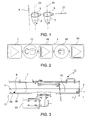
Fig. 1 is a schematized illustration of a row of objects having a first orientation and a second orientation, -
Fig. 2 is a schematized illustration of the object orienting method and corresponding functional units of the orienting device according to an embodiment of the invention; -
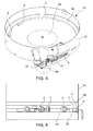
Fig. 3 is a sectional view of a single rotating disc selection device for a first orientation of the objects, for example, a top-bottom orientation, in accordance with an embodiment; -
Fig. 4 is a perspective view (with the upper lid being removed) of the selection device inFig. 3 ; -
Fig. 5 is an enlarged view of a detail inFig. 3 ; -
Fig. 6 is an enlarged view of a detail inFig. 4 ; -
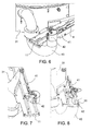
Figs. 7 and 8 illustrate a step of selecting properly positioned (Fig. 7 ) and improperly positioned objects (plugs) (Fig. 8 ) in a withdrawal path from the selection device inFig. 3 ; -
Fig. 9 is a perspective view of a double rotating disc selection device with selection alveoli according to an embodiment; -
Fig. 10 is a perspective view of a detail of the device inFig. 9 ; -
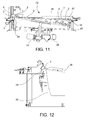
Fig. 11 is a vertical sectional view of the selection device inFig. 9 ; -
Fig. 12 is a sectional view of a detail of the selection device according to an embodiment; -
Figs. 13 and 14 are perspective views of a selection device with inclined rotating plate with selection alveoli according to an embodiment; -
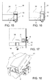
Figs. 15 and 16 illustrate a selection step by blowing with Venturi effect, which suctions properly positioned objects (Fig. 15 ) and with a pushing effect, which ejects improperly positioned objects (Fig. 16 ); -
Fig. 17 illustrates an object which is improperly positioned in a selection alveolus; -
Fig. 18 is an enlarged view of a detail of the selection device inFig. 14 ; -
Fig. 19 is a sectional view of a selection device according to a further alternative embodiment; -
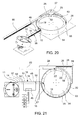
Fig. 20 is a schematized perspective view of a selection and orientation system with the selection device, of a build-up channel to build-up a row of preoriented objects, for example top-bottom, and an orienting device for a second orientation of the objects, for example, an angular orientation, in accordance with an embodiment; -
Fig. 21 is a top view of the system inFig. 20 ; - The
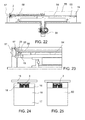
Fig. 22 is a cross-sectional view of the orienting device inFig. 20 . - The
Fig. 23 is an enlarged view of a detail inFig. 22 . - The
Fig. 24 is a cross-sectional view of the build-up channel according to an embodiment; - The
Fig. 25 is a cross-sectional view of a discharge channel of the fully oriented objects. - With reference to the figures, a
device 1 for orientingobjects 2 comprises: - a
support surface 3 movable along at least one length of aselection path 4 and suitable to receive theobjects 2 having a first orientation, wherein areference side 5 of theobject 2 faces a predetermined reference direction 6 (for example, a top-bottom orientation), - a
feeder 7 to convey/feed theobjects 2 onto thesupport surface 3 at astarting point 8 of theselection path 4, - selection means 9, 10 configured to prevent the
objects 2 with an orientation that is different from the first orientation from being received onto thesupport surface 3, or to eject theobjects 2 with an orientation that is different from the first orientation from thesupport surface 3, so as to obtain, at anoutput point 11 of theselection path 4, a sequence only ofobjects 2 having said first orientation. - Therefore, the
support surface 3, thefeeder 7, and the selection means 9,10 are part of a selection assembly ordevice 12 which, starting from bulk and randomly oriented objects 2, provides for arranging a sequence ofobjects 2 all having the same first orientation, for example a predetermined top-bottom orientation. - The orienting
device 1 further comprises: - a build-up
channel 13 having aninput opening 14 connected to theoutput point 11 of theselection path 4, anoutput opening 15, and aguide surface system 16 extending from the input opening 14 up to theoutput opening 15 so as to receive theobjects 2 with the first orientation in theinput opening 14 and to guide all theobjects 2 received in a single row and with a same (but not necessarily constant) first orientation from the input opening 14 to theoutput opening 15, - conveyor means 17 conveying each
single object 2 in the build-upchannel 13 towards theoutput opening 15 so as to form at the output opening 15 a single row ofobjects 2 brought mutually close (preferably in pressing contact) and having all a same first orientation. - In the present description, the term "convey" means both "to thrust" or "to move" in an active manner, e.g., by means of a transport by air, conveyor belt, or vibration, and "to guide" or "to accompany" in a passive manner, e.g., by means of build-up coils or guides for sliding or falling by gravity of the objects.
- Therefore, the build-up
channel 13 and the conveyor means 17 are part of a build-up assembly ordevice 18 which, starting from a sequence ofobjects 2 having a same first orientation, but a number of empty spaces, provides for arranging a single row ofobjects 2 brought mutually close (preferably in pressing contact) and having all a same first orientation. - The orienting
device 1 further comprises: - a sequence of
alveoli 19 movable along an orientingpath 20 extending from a receivingpoint 21 connected to theoutput opening 15 of the build-upchannel 13 up to arelease point 22, so that the build-upchannel 13 feeds into each of the alveoli 19 asingle object 2 with the first orientation and thealveoli 2 transport all theobjects 2 received with the same (but not necessarily constant) first orientation from the receivingpoint 21 to therelease point 22, - a friction or engage
surface 23 projecting in the orientingpath 20 so as to engage theobjects 2 received in the alveoli 19 and, due to the relative movement between the alveoli 19 and thefriction surface 23, to rotate theobjects 2 about areference axis thereof 24, - an
abutment surface 25 extending along analignment length 26 of the orientingpath 20 and forming an end-of-rotation abutment for theobjects 2 that reached a second orientation, in which theobject 2 is rotated about thereference axis 24 by a predetermined angle with respect to asecond reference direction 27 predetermined (for example, a radial orientation or alignment). - Therefore, the sequence of
alveoli 19, thefriction surface 23, and theabutment surface 25 are part of an angular orientation assembly ordevice 28 which, starting from a single row ofobjects 2 brought mutually close (preferably in pressing contact) and having all a same first orientation, provides for arranging a row ofobjects 2 brought close to each other and having all a same first orientation and a same second orientation. - By virtue of the subdivision of the orientation of the
objects 2 in independent steps of orientation (for example, top-bottom and angular), the moving rates along theselection path 4 and along the orientingpath 20 are not mutually constrained anymore and can be optimized for the single operation. Furthermore, the single orientation operations are less complex, hence they can be optimized and made quicker. The single selecting 4 and orienting 20 paths are much shorter than the overall orienting path of the prior art, allowing the use of smaller and/or quicker machines - However, the more relevant advantage is that the build-up
channel 13 which is interposed between theselection path 4 and the orientingpath 20 obviates the occurrence of empty alveoli 19. In fact, by virtue of the build-up of the row ofobjects 2, the orientation yield does not depend anymore on the causality of insertion into the alveoli and the first (top-bottom) orientation of theobjects 2 - In accordance with embodiments, the
selection assembly 12 can be configured as a rotary machine with a single rotating disc (Fig. 14 ), a rotary machine with double rotating disc (Fig. 9 ), a centrifugal rotary machine (Fig. 4 ) or a gravitational selection machine (Fig. 19 ). - In an embodiment (
Fig. 14 ), thesupport surface 3 is formed in asupport ring 29 extending along an outer circumference of (and integral with) arotating plate 30. Aside wall 31, circumferentially extending substantially along theentire selection path 4, defines theselection path 4 on a radially outer side thereof and, together with therotating plate 30, acollection space 32 to collect the bulk objects 2 to be oriented. The rotatingplate 30 is inclined and rotatable by amotor 33 in order to feed theobjects 2 from thecollection space 32 onto thesupport surface 3 and to move thesupport surface 3 along theselection path 4. - In the embodiment shown in
Fig. 9 (system with a double rotating disc), thesupport surface 3 is formed in asupport ring 34 of an outerrotating housing 35, which supportring 34 extends along an outer circumference of an innerrotating plate 36. Aside wall 31 extends circumferentially substantially along theentire selection path 4 and defines theselection path 4 on a radially outer side thereof. Thesupport ring 34 of the outerrotating housing 35 forms a radiallyinner surface 37 defining, together with innerrotating plate 36, acollection space 32 to collect the bulk objects 2 to be oriented. The innerrotating plate 36 is inclined and rotatable by afirst motor 33 to feed theobjects 2 from thecollection space 32 onto thesupport surface 3 of thesupport ring 34, and the outerrotating housing 35 is rotatable by asecond motor 38 to move thesupport surface 3 along theselection path 4. - In an embodiment (
Fig. 4 ), thesupport surface 3 is formed in asupport ring 29 extending along an outer circumference of (and integral with) arotating plate 30. Aside wall 31, circumferentially extending substantially along theentire selection path 4, defines theselection path 4 on a radially outer side thereof and, together with therotating plate 30, acollection space 32 to collect the bulk objects 2 to be oriented. The rotatingplate 30 lies in a substantially horizontal plane and is rotatable by amotor 33 in order to feed theobjects 2 from the collection space 32 (by means of the centrifugal force) onto thesupport surface 3 and to move thesupport surface 3 along theselection path 4. - In all the contemplated types of rotary machines, the
selection path 4 can be extending out of the machine itself, and, thus not necessarily limited only to thesupport ring 29 or only thesupport ring 34. According to the embodiment, the selection means 9, 10 can act on the circumferential length and/or on the outer length of theselection path 4. - - In an embodiment (
Fig. 19 ), thesupport surface 3 is formed by aconveyor belt 43 with a plurality ofshovels 44 arranged transversal to a longitudinal extension of theconveyor belt 43 itself. Theconveyor belt 43 receives the bulk objects 2 from ahopper 45 and forms anascending length 46 suitable to select theobjects 2 having the first orientation, so that, at the end of theascending length 46 only theobjects 2 having such first orientation are present on theconveyor belt 43. A withdrawingdevice 47, arranged downstream of theascending length 46 of theconveyor belt 43, is configured to withdraw theobjects 2 with the first orientation from theconveyor belt 43. To this aim, the withdrawingdevice 47 can comprise acasing 48 with a first wall and a second wall, which is opposite and faces the first wall, defining an interspace therebetween, which maintains the first orientation of theobjects 2 while they move (for example, fall due to the action of the force of gravity) towards theoutput point 11 of theselection path 4. In this case also, theselection path 4 extends out of its position as defined by theconveyor belt 43. - In accordance with embodiments, the selection means 9, 10 can comprise a sequence of
selection seats 9 formed in thesupport surface 3 and each being so shaped as to receive only one of theobjects 2 with the first orientation and to prevent theobjects 2 with an orientation that is different from the first orientation from being received. To this aim, theselection seats 9 can cooperate with aside wall 31 extending along theselection path 4 and ashaving surface 39 opposite thesupport surface 3. - Alternatively, the selection means 9, 10 can comprise a continuous channel that is formed by the
support surface 3, aside wall 31, and ashaving surface 39 opposite thesupport surface 3, wherein the continuous channel is so shaped as to receive only theobjects 2 with the first orientation and to prevent theobjects 2 with an orientation that is different from the first orientation from being received. - Alternatively or in addition, the selection means 9, 10 can comprise an
ejector 10, for example, a pneumatic blower directing an air jet to the electromechanical or mechanical selection path (for example, into theselection seats 9 or in the selection path), which displaces a small piston in the selection path (for example, into theselection seats 9 or in the selection path), configured to eject theobjects 2 with an orientation that is different from the first orientation from theselection path 4 and which preferably makes the ejectedobjects 2 to go back into the feeder, i.e., in thecollection space 32. - Alternatively or in addition, the selection means 9, 10 can comprise a mechanical deflector, for example, a
discontinuous support system 42, configured to unbalance and move theobjects 2 with an orientation that is different from the first orientation from theselection path 4 and which preferably makes the ejectedobjects 2 to go back into the feeder, i.e., in thecollection space 32. - For the return of the
objects 2 into thefeeder 7, areturn channel 40 can be provided, with associated pneumatic blower, particularly in the case that the ejection of theobjects 2 occurs in anend length 41 of theselection path 4 extending out of the rotary machine. - In accordance with an embodiment, the build-up
channel 13 comprises a tooempty detector 48 configured to generate and emit a too empty signal when the length of the row ofobjects 2 brought mutually close to each other (in contact) at theoutput opening 15 is less than a lower limit length. Acontrol unit 49 of thedevice 1 is in signal connection with the tooempty detector 48 and with theactuator motors support surface 3 and the alveoli 19 and controls the moving rate of thesupport surface 3 along theselection path 4 and/or the moving rate of the alveoli 19 along the orientingpath 20 also as a function of the too empty signal. - This allows controlling in a targeted manner the filling rate of the build-up
channel 13 to further decrease the risk of empty alveoli 19. - According to an embodiment, the too
empty detector 48 comprises an optical sensor, for example, a video camera or a photocell, which is configured to detect the passage ofobjects 2 in afirst detection point 50 in the build-upchannel 13 at a distance from theoutput opening 15 that is equal to the lower limit length, for example, 20 cm upstream of theoutput opening 15. Thecontrol unit 49 is configured to determine, based on the frequency of the passages of detected objects, if theobjects 2 are brought close to each other (in contact) along the entire row between thefirst detection point 50 and theoutput opening 15 or if such row comprises undesired empty spaces. - In accordance with a further embodiment, the build-up
channel 13 comprises anoverfill detector 51 configured to generate and emit a overfill signal when the length of the row ofobjects 2 brought close to each other (in mutual contact) at theoutput opening 15 is larger than an upper limit length. Thecontrol unit 49 of thedevice 1 is in signal connection with theoverfill detector 51 and with theactuator motors support surface 3 and of the alveoli 19 and controls the moving rate of thesupport surface 3 along theselection path 4 and/or the moving rate of the alveoli 19 along the orientingpath 20 also as a function of the overfill signal. - This allows preventing operation anomalies due to an excessive filling of the build-up
channel 13 with a sticking risk for theobjects 2. - According to an embodiment, the
overfill detector 51 comprises an optical sensor, for example, a video camera or a photocell, which is configured to detect the passage ofobjects 2 in asecond detection point 52 in the build-upchannel 13 at a distance from theoutput opening 15 that is equal to the upper limit length, for example, 30 cm downstream of theinput opening 14 and/or 80 cm upstream of theoutput opening 15. Thecontrol unit 49 is configured to determine, based on the frequency of the passages of detected objects, if theobjects 2 are brought mutually close (in contact) along the entire row between thesecond detection point 52 and theoutput opening 15 or if such row still comprises empty spaces, hence further receiving capacity. - In accordance with an embodiment, the conveyor means 17 can comprise:
- one or more air blowers arranged to direct one or more air jets in the build-up
channel 13 in the direction of theoutput opening 15 and/or - one or more conveyor belts or conveying brushes forming a conveying surface in contact with the
objects 2 and movable in the direction of theoutput opening 15 and/or - a gravitational conveyor formed by the
guide surface system 16 that are inclined so that theobjects 2 fall due to the action of the force of gravity towards theoutput opening 15. - In accordance with an embodiment (
Fig. 20 ), the alveoli 19 are formed in aperipheral ring 53 extending along an outer circumference of (and integral with) arotating plate 54. Aperipheral wall 55 extends circumferentially substantially along the entire orientingpath 20 and defines the orientingpath 20 on a radially outer side thereof. The rotatingplate 54 lies preferably in a horizontal plane and is rotatable by amotor 56 in order to move the alveoli 19 along the orientingpath 20. - In accordance with embodiments, the
friction surface 23 can be formed by: - a brush,
- a rubber or foamed rubber insert,
- a
belt 57 having a surface made of a high-friction material, e.g., rubber, foamed rubber, - Advantageously, the
friction surface 23 is mobile at a controlled speed (by thecontrol unit 49 or a dedicated control unit) along therotation length 58 of the orientingpath 20 so as to control the rotation rate of theobjects 2 about theirreference axis 24 independently from the moving speed of the alveoli 19 along the orientingpath 20. Particularly, thefriction surface 23 is mobile in a direction opposite the movement direction of the alveoli 19, so as to increase the rotation angle of theobjects 2 while keeping the length of therotation length 58 of the orientingpath 20 constant. - This further increases the orientation speed, while keeping the device dimension and the moving rate of the same objects constant.
- Alternatively, the
friction surface 23 can be mobile in the movement direction of the alveoli 19, so as to decrease the rotation rate of theobjects 2 while keeping the constant moving rate of the alveoli 19, for example preventing undesired relative slidings between thefriction surface 23 and theobject 2. - The controlled handling of the
friction surface 23 is carried out by means of special actuation means, for example, anelectric motor 59 connected to thebelt 57 or as series of rotary brushes. In a further embodiment, thebelt 57 itself is provided with bristles to create a brush-like friction surface 23. - A
discharge channel 60 can be connected to therelease point 22 of the orientingpath 20, which is suitable to receive and convey theobjects 2 to successive working station, while maintaining the first and second orientations thereof.
Claims (15)
- A device (1) for orienting objects (2), comprising:- a support surface (3) movable along at least one length of a selection path (4) and suitable to receive the objects (2) having a first orientation, wherein a reference side (5) of the object (2) faces in a predetermined reference direction (6),- a feeder (7) to feed the objects (2) on the support surface (3) at a starting point (8) of the selection path (4),- selection means (9, 10) configured to prevent the objects (2) with an orientation that is different from the first orientation from being received onto the support surface (3), or to eject the objects (2) with an orientation that is different from the first orientation from the selection path (4), so as to obtain, at an output point (11) of the selection path (4), a sequence only of objects (2) having said first orientation,- a build-up channel (13) having an input opening (14) connected to the output point (11) of the selection path (4), an output opening (15), and a guide surface system (16) extending from the input opening (14) up to the output opening (15), so as to receive the objects (2) with the first orientation in the input opening (14) and to guide the received objects (2) in a single row and having all the same first orientation from the input opening (14) to the output opening (15),- conveyor means (17) conveying each single object (2) in the build-up channel (13) towards the output opening (15) so as to form at the output opening (15) a single row of objects (2) brought close to each other and all having the same first orientation,- a sequence of alveoli (19) movable along a orienting path (20) extending from a receiving point (21) connected to the output opening (15) of the build-up channel (13) up to a release point (22), so that the build-up channel (13) feeds in each of the alveoli (19) a single object (2) with the first orientation and the alveoli (2) transport all the objects (2) received with the same first orientation from the receiving point (21) to the release point (22),- a friction surface (23) projecting in the orienting path (20) so as to engage the objects (2) received in the alveoli (19) and, due to the relative movement between the alveoli (19) and the friction surface (23), rotate the objects (2) about a reference axis (24) thereof,- an abutment surface (25) extending along an alignment length (26) of the orienting path (20) and forming an end-of-rotation abutment for the objects (2) that reached a second orientation, in which the object (2) is rotated about the reference axis (24) by a predetermined angle with respect to a second predetermined reference direction (27).
- The device (1) according to claim 1, wherein the build-up channel (13) comprises a too empty detector (48) configured to generate and emit a too empty signal when the length of the row of objects (2) brought close to each other at the output opening (15) is less than a lower limit length, wherein an electronic control unit (49) of the device (1) is in signal connection with the too empty detector (48) and with an actuator (33, 38) of the support surface (3) and controls the moving rate of the support surface (3) as a function of the too empty signal.
- The device (1) according to claim 2, wherein:- the too empty detector (48) comprises an optical sensor configured to detect the passage of objects (2) in a first detection point (50) in the build-up channel (13) at a distance from the output opening (15) that is equal to the lower limit length,- the control unit (49) is configured to determine, based on the frequency of the passages of detected objects, if the objects (2) are brought close to each other along the entire row between the first detection point (50) and the output opening (15).
- The device (1) according to one of the claims 2 or 3, wherein:- the build-up channel (13) comprises an overfill detector (51) configured to generate and emit an overfill signal when the length of the row of objects (2) brought close to each other at the output opening (15) is larger than an upper limit length,- the control unit (49) is in signal connection with the overfill detector (51) and with the actuator (33, 38) of the support surface (3), and controls the moving rate of the support surface (3) as a function of the overfill signal.
- The device (1) according to claim 4, wherein the overfill detector (51) comprises an optical sensor configured to detect the passage of objects (2) in a second detection point (52) in the build-up channel (13) at a distance from the output opening (15) that is equal to the upper limit length,- the control unit (49) is configured to determine, based on the frequency of the passages of detected objects, if the objects (2) are brought close to each other along the entire row between the second detection point (52) and the output opening (15).
- The device (1) according to any of the preceding claims, wherein the conveyor means (17) comprise one of:- one or more air blowers arranged to direct one or more air jets into the build-up channel (13) in the direction of the output opening 15,- one or more conveyor belts or conveying brushes forming a conveying surface in contact with the objects (2) and movable in the direction of the output opening (15),- a gravitational conveyor formed by the system of guide surfaces (16) that are inclined so that the objects (2) fall due to the action of gravity towards the output opening (15).
- The device (1) according to any of the preceding claims, wherein:- the alveoli (19) are formed in a peripheral ring (53) extending along an outer circumference of a rotating plate (54),- the rotating plate (54) is rotatable by a motor (56) in order to move the alveoli (19) along the orienting path (20),- the friction surface (23) is mobile at a controlled speed along a rotation length (58) of the orienting path (20) so as to controlthe rotation rate of the objects (2) about their reference axis (24) independently from the moving speed of the alveoli (19) along the orienting path (20).
- The device (1) according to claim 7, wherein:- the friction surface (23) is formed by a belt (57) that is actuated by an electric motor (59).
- The device (1) according to one of the preceding claims, wherein:- the support surface (3) is formed in a support ring (29) extending along an outer circumference of a rotating plate (30),- a side wall (31) extends circumferentially along a prevailing part of the selection path (4) so as to define, together with the rotating plate (30), a collection space (32) to collect the bulk objects (2) to be oriented,- the rotating plate (30) is inclined and rotatable by a motor (33) in order to feed the objects (2) from the collection space (32) onto the support surface (3) and to move the support surface (3) along the selection path (4).
- The device (1) according to one of the claims 1 to 8, wherein:- the support surface (3) is formed in a support ring (34) of an outer rotating housing (35), said support ring (34) extending along an outer circumference of an inner rotating plate (36),- the support ring (34) of the outer rotating housing (35) forms a radially inner surface (37) defining, together with the inner rotating plate (36), a collection space (32) to collect the bulk objects (2) to be oriented,- the inner rotating plate (36) is inclined and rotatable by a first motor (33) to feed the objects (2) from the collection space (32) onto the support surface (3) of the support ring (34),- the outer rotating housing (35) is rotatable by a second motor (38) to move the support surface (3) along the selection path (4).
- The device (1) according to one of the claims 1 to 8, wherein:- the support surface (3) is formed in a support ring (29) extending along an outer circumference of a rotating plate (30),- a side wall (31) extends circumferentially along a prevailing part of the selection path (4) and defines, together with the rotating plate (30), a collection space (32) to collect the bulk objects (2) to be oriented,- the rotating plate (30) lies in a substantially horizontal plane, and is rotatable by a motor (33) so as to feed the objects (2) from the collection space (32) by means of the centrifugal force onto the support surface (3), and to move the support surface (3) along the selection path (4).
- The device (1) according to one of the claims 1 to 8, wherein:- the support surface (3) is formed by a conveyor belt (43) with a plurality of shovels (44) arranged transversal to a longitudinal extension of the conveyor belt (43),- the conveyor belt (43) is located to receive the bulk objects (2) from a hopper (45), and forms an ascending length (46) suitable to select the objects (2) having the first orientation, so that, at the end of the ascending length (46), only the objects (2) having the first orientation are present on the conveyor belt (43).
- The device (1) according to one of the preceding claims, wherein the selection means (9, 10) comprise at least one of:- a sequence of selection seats (9) formed in the support surface (3) and each being so shaped as to receive only one of the objects (2) with the first orientation, and to prevent the objects (2) with an orientation that is different from the first orientation from being received,- a shaving surface (39) opposite the support surface (3),- a continuous channel that is formed by the support surface (3), a side wall (31), and a shaving surface (39) opposite the support surface (3), said continuous channel being so shaped as to receive only the objects (2) with the first orientation, and to prevent the objects (2) with an orientation that is different from the first orientation from being received,- a pneumatic ejector (10) directing an air jet to the selection path in order to eject from the selection path (4) the objects (2) with an orientation that is different from the first orientation,- a discontinuous support system (42) that is configured to unbalance and remove from the selection path (4) the objects (2) with an orientation that is different from the first orientation.
- A method for orienting objects (2), comprising the steps of:- moving a support surface (3) along at least one length of a selection path (4),- feeding the objects (2) onto the support surface (3) at a starting point (8) of the selection path (4),- ejecting the objects (2) with an orientation that is different from a first orientation from the selection path (4), in which a reference side (5) of the object (2) faces a predetermined reference direction (6), so as to obtain, at an output point (11) of the selection path (4), a sequence only of objects (2) having said first orientation,- receiving the objects (2) with the first orientation at the output point (11) of the selection path (4) and bring the objects (2) mutually close, so as to form a single row of objects (2) brought mutually close and all having the same first orientation,- moving a sequence of alveoli (19) along an orienting path (20) extending from a receiving point (21) up to a release point (22),- feeding the single row of mutually approximated objects (2) to the receiving point (21) so that each of the alveoli (19) receives a single object (2) with the first orientation and the alveoli (2) transport all the objects (2) received with the same first orientation from the receiving point (21) to the release point (22),- extending a friction surface (23) in the orientation path (20) so that the friction surface (23) engages the objects (2) received within the alveoli (19) and rotates the objects (2) about a reference axis (24) thereof due to the relative movement between the alveoli (19) and the friction surface (23),- locking the rotation of the objects (2) that reached a second orientation, in which the object (2) is rotated about the reference axis (24) by a predetermined angle with respect to a second predetermined reference direction (27).
- The method according to claim 14, comprising the step of:- moving the friction surface to the opposite direction with respect to the movement of the alveoli.
Applications Claiming Priority (1)
| Application Number | Priority Date | Filing Date | Title |
|---|---|---|---|
| IT002070A ITMI20132070A1 (en) | 2013-12-12 | 2013-12-12 | SYSTEM AND METHOD FOR ORIENTATION OF OBJECTS |
Publications (2)
| Publication Number | Publication Date |
|---|---|
| EP2883818A1 true EP2883818A1 (en) | 2015-06-17 |
| EP2883818B1 EP2883818B1 (en) | 2016-08-17 |
Family
ID=50073296
Family Applications (1)
| Application Number | Title | Priority Date | Filing Date |
|---|---|---|---|
| EP14190992.9A Active EP2883818B1 (en) | 2013-12-12 | 2014-10-30 | System and method for orienting objects |
Country Status (2)
| Country | Link |
|---|---|
| EP (1) | EP2883818B1 (en) |
| IT (1) | ITMI20132070A1 (en) |
Cited By (5)
| Publication number | Priority date | Publication date | Assignee | Title |
|---|---|---|---|---|
| CN107043006A (en) * | 2017-01-10 | 2017-08-15 | 无锡市通达滚子有限公司 | It is a kind of that the feed arrangement of self-feeding can be realized to pin tooth |
| DE102018103674A1 (en) * | 2018-02-19 | 2019-08-22 | Ejot Gmbh & Co. Kg | Device for processing elements |
| CN114684415A (en) * | 2020-12-30 | 2022-07-01 | 莫迪维克西普哈根牧勒股份及两合公司 | Steering device for products |
| EP4219354A1 (en) * | 2022-02-01 | 2023-08-02 | Weightpack S.r.l. | Spray container pump sorting machine |
| DE102022003188A1 (en) | 2022-09-01 | 2024-03-07 | Peter Groppenbächer | Device for conveying conveyed goods |
Citations (3)
| Publication number | Priority date | Publication date | Assignee | Title |
|---|---|---|---|---|
| CH543343A (en) * | 1972-01-03 | 1973-10-31 | Rationator Maschb Wilhelm Meck | Device for feeding and continuously arranging cylindrical mass parts |
| EP1281643A1 (en) * | 2000-03-31 | 2003-02-05 | Jaime Marti Sala | Automatic linear machine for orienting and aligning articles |
| EP2404849A1 (en) * | 2010-07-05 | 2012-01-11 | Bonino S.p.A. | Object orienting device |
-
2013
- 2013-12-12 IT IT002070A patent/ITMI20132070A1/en unknown
-
2014
- 2014-10-30 EP EP14190992.9A patent/EP2883818B1/en active Active
Patent Citations (3)
| Publication number | Priority date | Publication date | Assignee | Title |
|---|---|---|---|---|
| CH543343A (en) * | 1972-01-03 | 1973-10-31 | Rationator Maschb Wilhelm Meck | Device for feeding and continuously arranging cylindrical mass parts |
| EP1281643A1 (en) * | 2000-03-31 | 2003-02-05 | Jaime Marti Sala | Automatic linear machine for orienting and aligning articles |
| EP2404849A1 (en) * | 2010-07-05 | 2012-01-11 | Bonino S.p.A. | Object orienting device |
Cited By (5)
| Publication number | Priority date | Publication date | Assignee | Title |
|---|---|---|---|---|
| CN107043006A (en) * | 2017-01-10 | 2017-08-15 | 无锡市通达滚子有限公司 | It is a kind of that the feed arrangement of self-feeding can be realized to pin tooth |
| DE102018103674A1 (en) * | 2018-02-19 | 2019-08-22 | Ejot Gmbh & Co. Kg | Device for processing elements |
| CN114684415A (en) * | 2020-12-30 | 2022-07-01 | 莫迪维克西普哈根牧勒股份及两合公司 | Steering device for products |
| EP4219354A1 (en) * | 2022-02-01 | 2023-08-02 | Weightpack S.r.l. | Spray container pump sorting machine |
| DE102022003188A1 (en) | 2022-09-01 | 2024-03-07 | Peter Groppenbächer | Device for conveying conveyed goods |
Also Published As
| Publication number | Publication date |
|---|---|
| ITMI20132070A1 (en) | 2015-06-13 |
| EP2883818B1 (en) | 2016-08-17 |
Similar Documents
| Publication | Publication Date | Title |
|---|---|---|
| EP2883818B1 (en) | System and method for orienting objects | |
| US8783439B2 (en) | Method and machine for preparing stoppers, caps, or other types of objects | |
| US6799413B2 (en) | Apparatus and methods for filling containers with pills | |
| US20130098812A1 (en) | Device for preparaing sealing elements | |
| JPH01247042A (en) | Apparatus for sorting and feeding sugar confectionery | |
| JP2017510523A (en) | Supply unit | |
| CN107108131B (en) | Device and method for reliably supplying satisfactory closure elements | |
| KR102124222B1 (en) | Buffer for brushes | |
| KR20210134629A (en) | Counter filler device for counting pharmaceutical articles and inserting articles into the interior of bottles | |
| JP2002029516A (en) | Device for recovering surplus product on blister band in blistering device | |
| EP2404849B1 (en) | Object orienting device | |
| EP3378336B1 (en) | Method and device for separating fruits from wooden shells of almonds | |
| US10501268B2 (en) | Referenced feeding of capsules | |
| EP1842826B1 (en) | Device for feeding articles, in particular corks, to a pick-up station | |
| CN105410962A (en) | Mushroom drying device | |
| US20050155842A1 (en) | Unit and method for reordering confectionery products, such as sweets and similar | |
| EP2226276A1 (en) | Object orienting device | |
| EP3107845B1 (en) | Object orienting machine | |
| JP7159298B2 (en) | Manufacturing machine for the production of disposable cartridges for electronic cigarettes | |
| CN111319947A (en) | Bead feeding method and bead feeding unit | |
| US10399259B2 (en) | Rotary tablet press | |
| EP3089600B1 (en) | Apparatus and method for introducing objects into a flow of filter material | |
| EP3466664B1 (en) | Molded product discharge device | |
| EP2803606B1 (en) | Object orienting device | |
| KR102485520B1 (en) | Automatic deburring apparatus of battery can |
Legal Events
| Date | Code | Title | Description |
|---|---|---|---|
| PUAI | Public reference made under article 153(3) epc to a published international application that has entered the european phase |
Free format text: ORIGINAL CODE: 0009012 |
|
| 17P | Request for examination filed |
Effective date: 20141030 |
|
| AK | Designated contracting states |
Kind code of ref document: A1 Designated state(s): AL AT BE BG CH CY CZ DE DK EE ES FI FR GB GR HR HU IE IS IT LI LT LU LV MC MK MT NL NO PL PT RO RS SE SI SK SM TR |
|
| AX | Request for extension of the european patent |
Extension state: BA ME |
|
| R17P | Request for examination filed (corrected) |
Effective date: 20151126 |
|
| RBV | Designated contracting states (corrected) |
Designated state(s): AL AT BE BG CH CY CZ DE DK EE ES FI FR GB GR HR HU IE IS IT LI LT LU LV MC MK MT NL NO PL PT RO RS SE SI SK SM TR |
|
| GRAP | Despatch of communication of intention to grant a patent |
Free format text: ORIGINAL CODE: EPIDOSNIGR1 |
|
| RIC1 | Information provided on ipc code assigned before grant |
Ipc: B65G 47/256 20060101ALI20160215BHEP Ipc: B65G 47/14 20060101ALI20160215BHEP Ipc: B65G 29/00 20060101AFI20160215BHEP |
|
| INTG | Intention to grant announced |
Effective date: 20160302 |
|
| GRAS | Grant fee paid |
Free format text: ORIGINAL CODE: EPIDOSNIGR3 |
|
| GRAA | (expected) grant |
Free format text: ORIGINAL CODE: 0009210 |
|
| AK | Designated contracting states |
Kind code of ref document: B1 Designated state(s): AL AT BE BG CH CY CZ DE DK EE ES FI FR GB GR HR HU IE IS IT LI LT LU LV MC MK MT NL NO PL PT RO RS SE SI SK SM TR |
|
| REG | Reference to a national code |
Ref country code: GB Ref legal event code: FG4D |
|
| REG | Reference to a national code |
Ref country code: CH Ref legal event code: EP |
|
| REG | Reference to a national code |
Ref country code: IE Ref legal event code: FG4D |
|
| REG | Reference to a national code |
Ref country code: AT Ref legal event code: REF Ref document number: 820831 Country of ref document: AT Kind code of ref document: T Effective date: 20160915 |
|
| REG | Reference to a national code |
Ref country code: DE Ref legal event code: R096 Ref document number: 602014003094 Country of ref document: DE |
|
| REG | Reference to a national code |
Ref country code: FR Ref legal event code: PLFP Year of fee payment: 3 |
|
| REG | Reference to a national code |
Ref country code: SE Ref legal event code: TRGR |
|
| REG | Reference to a national code |
Ref country code: NL Ref legal event code: MP Effective date: 20160817 |
|
| REG | Reference to a national code |
Ref country code: LT Ref legal event code: MG4D |
|
| REG | Reference to a national code |
Ref country code: AT Ref legal event code: MK05 Ref document number: 820831 Country of ref document: AT Kind code of ref document: T Effective date: 20160817 |
|
| PG25 | Lapsed in a contracting state [announced via postgrant information from national office to epo] |
Ref country code: LT Free format text: LAPSE BECAUSE OF FAILURE TO SUBMIT A TRANSLATION OF THE DESCRIPTION OR TO PAY THE FEE WITHIN THE PRESCRIBED TIME-LIMIT Effective date: 20160817 Ref country code: RS Free format text: LAPSE BECAUSE OF FAILURE TO SUBMIT A TRANSLATION OF THE DESCRIPTION OR TO PAY THE FEE WITHIN THE PRESCRIBED TIME-LIMIT Effective date: 20160817 Ref country code: NO Free format text: LAPSE BECAUSE OF FAILURE TO SUBMIT A TRANSLATION OF THE DESCRIPTION OR TO PAY THE FEE WITHIN THE PRESCRIBED TIME-LIMIT Effective date: 20161117 Ref country code: IT Free format text: LAPSE BECAUSE OF FAILURE TO SUBMIT A TRANSLATION OF THE DESCRIPTION OR TO PAY THE FEE WITHIN THE PRESCRIBED TIME-LIMIT Effective date: 20160817 Ref country code: HR Free format text: LAPSE BECAUSE OF FAILURE TO SUBMIT A TRANSLATION OF THE DESCRIPTION OR TO PAY THE FEE WITHIN THE PRESCRIBED TIME-LIMIT Effective date: 20160817 Ref country code: NL Free format text: LAPSE BECAUSE OF FAILURE TO SUBMIT A TRANSLATION OF THE DESCRIPTION OR TO PAY THE FEE WITHIN THE PRESCRIBED TIME-LIMIT Effective date: 20160817 Ref country code: FI Free format text: LAPSE BECAUSE OF FAILURE TO SUBMIT A TRANSLATION OF THE DESCRIPTION OR TO PAY THE FEE WITHIN THE PRESCRIBED TIME-LIMIT Effective date: 20160817 |
|
| PG25 | Lapsed in a contracting state [announced via postgrant information from national office to epo] |
Ref country code: AT Free format text: LAPSE BECAUSE OF FAILURE TO SUBMIT A TRANSLATION OF THE DESCRIPTION OR TO PAY THE FEE WITHIN THE PRESCRIBED TIME-LIMIT Effective date: 20160817 Ref country code: PL Free format text: LAPSE BECAUSE OF FAILURE TO SUBMIT A TRANSLATION OF THE DESCRIPTION OR TO PAY THE FEE WITHIN THE PRESCRIBED TIME-LIMIT Effective date: 20160817 Ref country code: ES Free format text: LAPSE BECAUSE OF FAILURE TO SUBMIT A TRANSLATION OF THE DESCRIPTION OR TO PAY THE FEE WITHIN THE PRESCRIBED TIME-LIMIT Effective date: 20160817 Ref country code: BE Free format text: LAPSE BECAUSE OF NON-PAYMENT OF DUE FEES Effective date: 20161031 Ref country code: LV Free format text: LAPSE BECAUSE OF FAILURE TO SUBMIT A TRANSLATION OF THE DESCRIPTION OR TO PAY THE FEE WITHIN THE PRESCRIBED TIME-LIMIT Effective date: 20160817 Ref country code: GR Free format text: LAPSE BECAUSE OF FAILURE TO SUBMIT A TRANSLATION OF THE DESCRIPTION OR TO PAY THE FEE WITHIN THE PRESCRIBED TIME-LIMIT Effective date: 20161118 Ref country code: PT Free format text: LAPSE BECAUSE OF FAILURE TO SUBMIT A TRANSLATION OF THE DESCRIPTION OR TO PAY THE FEE WITHIN THE PRESCRIBED TIME-LIMIT Effective date: 20161219 |
|
| PG25 | Lapsed in a contracting state [announced via postgrant information from national office to epo] |
Ref country code: EE Free format text: LAPSE BECAUSE OF FAILURE TO SUBMIT A TRANSLATION OF THE DESCRIPTION OR TO PAY THE FEE WITHIN THE PRESCRIBED TIME-LIMIT Effective date: 20160817 Ref country code: RO Free format text: LAPSE BECAUSE OF FAILURE TO SUBMIT A TRANSLATION OF THE DESCRIPTION OR TO PAY THE FEE WITHIN THE PRESCRIBED TIME-LIMIT Effective date: 20160817 |
|
| REG | Reference to a national code |
Ref country code: DE Ref legal event code: R097 Ref document number: 602014003094 Country of ref document: DE |
|
| PG25 | Lapsed in a contracting state [announced via postgrant information from national office to epo] |
Ref country code: CZ Free format text: LAPSE BECAUSE OF FAILURE TO SUBMIT A TRANSLATION OF THE DESCRIPTION OR TO PAY THE FEE WITHIN THE PRESCRIBED TIME-LIMIT Effective date: 20160817 Ref country code: BE Free format text: LAPSE BECAUSE OF FAILURE TO SUBMIT A TRANSLATION OF THE DESCRIPTION OR TO PAY THE FEE WITHIN THE PRESCRIBED TIME-LIMIT Effective date: 20160817 Ref country code: SM Free format text: LAPSE BECAUSE OF FAILURE TO SUBMIT A TRANSLATION OF THE DESCRIPTION OR TO PAY THE FEE WITHIN THE PRESCRIBED TIME-LIMIT Effective date: 20160817 Ref country code: DK Free format text: LAPSE BECAUSE OF FAILURE TO SUBMIT A TRANSLATION OF THE DESCRIPTION OR TO PAY THE FEE WITHIN THE PRESCRIBED TIME-LIMIT Effective date: 20160817 Ref country code: SK Free format text: LAPSE BECAUSE OF FAILURE TO SUBMIT A TRANSLATION OF THE DESCRIPTION OR TO PAY THE FEE WITHIN THE PRESCRIBED TIME-LIMIT Effective date: 20160817 Ref country code: BG Free format text: LAPSE BECAUSE OF FAILURE TO SUBMIT A TRANSLATION OF THE DESCRIPTION OR TO PAY THE FEE WITHIN THE PRESCRIBED TIME-LIMIT Effective date: 20161117 |
|
| PLBE | No opposition filed within time limit |
Free format text: ORIGINAL CODE: 0009261 |
|
| STAA | Information on the status of an ep patent application or granted ep patent |
Free format text: STATUS: NO OPPOSITION FILED WITHIN TIME LIMIT |
|
| 26N | No opposition filed |
Effective date: 20170518 |
|
| REG | Reference to a national code |
Ref country code: IE Ref legal event code: MM4A |
|
| PG25 | Lapsed in a contracting state [announced via postgrant information from national office to epo] |
Ref country code: SI Free format text: LAPSE BECAUSE OF FAILURE TO SUBMIT A TRANSLATION OF THE DESCRIPTION OR TO PAY THE FEE WITHIN THE PRESCRIBED TIME-LIMIT Effective date: 20160817 Ref country code: LU Free format text: LAPSE BECAUSE OF NON-PAYMENT OF DUE FEES Effective date: 20161030 |
|
| REG | Reference to a national code |
Ref country code: FR Ref legal event code: PLFP Year of fee payment: 4 |
|
| PG25 | Lapsed in a contracting state [announced via postgrant information from national office to epo] |
Ref country code: IE Free format text: LAPSE BECAUSE OF NON-PAYMENT OF DUE FEES Effective date: 20161030 |
|
| PG25 | Lapsed in a contracting state [announced via postgrant information from national office to epo] |
Ref country code: HU Free format text: LAPSE BECAUSE OF FAILURE TO SUBMIT A TRANSLATION OF THE DESCRIPTION OR TO PAY THE FEE WITHIN THE PRESCRIBED TIME-LIMIT; INVALID AB INITIO Effective date: 20141030 |
|
| REG | Reference to a national code |
Ref country code: CH Ref legal event code: PL |
|
| PG25 | Lapsed in a contracting state [announced via postgrant information from national office to epo] |
Ref country code: MT Free format text: LAPSE BECAUSE OF NON-PAYMENT OF DUE FEES Effective date: 20161031 Ref country code: CY Free format text: LAPSE BECAUSE OF FAILURE TO SUBMIT A TRANSLATION OF THE DESCRIPTION OR TO PAY THE FEE WITHIN THE PRESCRIBED TIME-LIMIT Effective date: 20160817 Ref country code: IS Free format text: LAPSE BECAUSE OF FAILURE TO SUBMIT A TRANSLATION OF THE DESCRIPTION OR TO PAY THE FEE WITHIN THE PRESCRIBED TIME-LIMIT Effective date: 20160817 Ref country code: MK Free format text: LAPSE BECAUSE OF FAILURE TO SUBMIT A TRANSLATION OF THE DESCRIPTION OR TO PAY THE FEE WITHIN THE PRESCRIBED TIME-LIMIT Effective date: 20160817 Ref country code: MC Free format text: LAPSE BECAUSE OF FAILURE TO SUBMIT A TRANSLATION OF THE DESCRIPTION OR TO PAY THE FEE WITHIN THE PRESCRIBED TIME-LIMIT Effective date: 20160817 |
|
| PG25 | Lapsed in a contracting state [announced via postgrant information from national office to epo] |
Ref country code: LI Free format text: LAPSE BECAUSE OF NON-PAYMENT OF DUE FEES Effective date: 20171031 Ref country code: CH Free format text: LAPSE BECAUSE OF NON-PAYMENT OF DUE FEES Effective date: 20171031 |
|
| PG25 | Lapsed in a contracting state [announced via postgrant information from national office to epo] |
Ref country code: AL Free format text: LAPSE BECAUSE OF FAILURE TO SUBMIT A TRANSLATION OF THE DESCRIPTION OR TO PAY THE FEE WITHIN THE PRESCRIBED TIME-LIMIT Effective date: 20160817 Ref country code: TR Free format text: LAPSE BECAUSE OF FAILURE TO SUBMIT A TRANSLATION OF THE DESCRIPTION OR TO PAY THE FEE WITHIN THE PRESCRIBED TIME-LIMIT Effective date: 20160817 |
|
| REG | Reference to a national code |
Ref country code: FR Ref legal event code: PLFP Year of fee payment: 5 |
|
| GBPC | Gb: european patent ceased through non-payment of renewal fee |
Effective date: 20181030 |
|
| PG25 | Lapsed in a contracting state [announced via postgrant information from national office to epo] |
Ref country code: GB Free format text: LAPSE BECAUSE OF NON-PAYMENT OF DUE FEES Effective date: 20181030 |
|
| REG | Reference to a national code |
Ref country code: DE Ref legal event code: R081 Ref document number: 602014003094 Country of ref document: DE Owner name: BONINO S.R.L., IT Free format text: FORMER OWNER: BONINO S.P.A. CON UNICO AZIONISTA, ALESSANDRIA, IT |
|
| PGFP | Annual fee paid to national office [announced via postgrant information from national office to epo] |
Ref country code: SE Payment date: 20231017 Year of fee payment: 10 Ref country code: FR Payment date: 20231124 Year of fee payment: 11 Ref country code: DE Payment date: 20231020 Year of fee payment: 10 |