EP2883738B1 - Method and assembly for controlling functions of a motor vehicle - Google Patents
Method and assembly for controlling functions of a motor vehicle Download PDFInfo
- Publication number
- EP2883738B1 EP2883738B1 EP14002599.0A EP14002599A EP2883738B1 EP 2883738 B1 EP2883738 B1 EP 2883738B1 EP 14002599 A EP14002599 A EP 14002599A EP 2883738 B1 EP2883738 B1 EP 2883738B1
- Authority
- EP
- European Patent Office
- Prior art keywords
- steering wheel
- evaluation unit
- predefined
- movement
- unit
- Prior art date
- Legal status (The legal status is an assumption and is not a legal conclusion. Google has not performed a legal analysis and makes no representation as to the accuracy of the status listed.)
- Active
Links
- 238000000034 method Methods 0.000 title claims description 41
- 230000006870 function Effects 0.000 title claims description 35
- 230000033001 locomotion Effects 0.000 claims description 102
- 238000011156 evaluation Methods 0.000 claims description 78
- 210000003813 thumb Anatomy 0.000 claims description 39
- 210000003811 finger Anatomy 0.000 claims description 24
- 230000008859 change Effects 0.000 claims description 11
- 230000003287 optical effect Effects 0.000 claims description 8
- 230000001960 triggered effect Effects 0.000 claims description 6
- 239000000463 material Substances 0.000 claims description 3
- 230000000007 visual effect Effects 0.000 claims description 3
- 230000000712 assembly Effects 0.000 claims 1
- 238000000429 assembly Methods 0.000 claims 1
- 238000001514 detection method Methods 0.000 description 9
- 238000013461 design Methods 0.000 description 6
- 230000008569 process Effects 0.000 description 5
- 210000004935 right thumb Anatomy 0.000 description 5
- 230000003068 static effect Effects 0.000 description 4
- 230000008901 benefit Effects 0.000 description 3
- 230000004069 differentiation Effects 0.000 description 3
- 210000004247 hand Anatomy 0.000 description 3
- 210000004936 left thumb Anatomy 0.000 description 3
- 230000005236 sound signal Effects 0.000 description 3
- 230000004913 activation Effects 0.000 description 2
- 230000001276 controlling effect Effects 0.000 description 2
- 230000000875 corresponding effect Effects 0.000 description 2
- 238000011161 development Methods 0.000 description 2
- 230000018109 developmental process Effects 0.000 description 2
- 238000010079 rubber tapping Methods 0.000 description 2
- 238000002604 ultrasonography Methods 0.000 description 2
- 230000005355 Hall effect Effects 0.000 description 1
- 230000003213 activating effect Effects 0.000 description 1
- 230000006978 adaptation Effects 0.000 description 1
- 238000004378 air conditioning Methods 0.000 description 1
- 238000004458 analytical method Methods 0.000 description 1
- 238000003491 array Methods 0.000 description 1
- 239000003086 colorant Substances 0.000 description 1
- 230000010485 coping Effects 0.000 description 1
- 230000002596 correlated effect Effects 0.000 description 1
- 230000001419 dependent effect Effects 0.000 description 1
- 230000012447 hatching Effects 0.000 description 1
- 230000001939 inductive effect Effects 0.000 description 1
- 238000005259 measurement Methods 0.000 description 1
- 230000000284 resting effect Effects 0.000 description 1
- 230000011664 signaling Effects 0.000 description 1
- 239000013589 supplement Substances 0.000 description 1
- 238000010408 sweeping Methods 0.000 description 1
- 238000012546 transfer Methods 0.000 description 1
Images

Classifications
-
- B60K35/10—
-
- G—PHYSICS
- G06—COMPUTING; CALCULATING OR COUNTING
- G06F—ELECTRIC DIGITAL DATA PROCESSING
- G06F3/00—Input arrangements for transferring data to be processed into a form capable of being handled by the computer; Output arrangements for transferring data from processing unit to output unit, e.g. interface arrangements
- G06F3/01—Input arrangements or combined input and output arrangements for interaction between user and computer
- G06F3/017—Gesture based interaction, e.g. based on a set of recognized hand gestures
-
- B60K35/60—
-
- B60K35/654—
-
- G—PHYSICS
- G06—COMPUTING; CALCULATING OR COUNTING
- G06F—ELECTRIC DIGITAL DATA PROCESSING
- G06F3/00—Input arrangements for transferring data to be processed into a form capable of being handled by the computer; Output arrangements for transferring data from processing unit to output unit, e.g. interface arrangements
- G06F3/01—Input arrangements or combined input and output arrangements for interaction between user and computer
- G06F3/03—Arrangements for converting the position or the displacement of a member into a coded form
- G06F3/0304—Detection arrangements using opto-electronic means
-
- G—PHYSICS
- G06—COMPUTING; CALCULATING OR COUNTING
- G06F—ELECTRIC DIGITAL DATA PROCESSING
- G06F3/00—Input arrangements for transferring data to be processed into a form capable of being handled by the computer; Output arrangements for transferring data from processing unit to output unit, e.g. interface arrangements
- G06F3/01—Input arrangements or combined input and output arrangements for interaction between user and computer
- G06F3/03—Arrangements for converting the position or the displacement of a member into a coded form
- G06F3/041—Digitisers, e.g. for touch screens or touch pads, characterised by the transducing means
- G06F3/042—Digitisers, e.g. for touch screens or touch pads, characterised by the transducing means by opto-electronic means
- G06F3/0425—Digitisers, e.g. for touch screens or touch pads, characterised by the transducing means by opto-electronic means using a single imaging device like a video camera for tracking the absolute position of a single or a plurality of objects with respect to an imaged reference surface, e.g. video camera imaging a display or a projection screen, a table or a wall surface, on which a computer generated image is displayed or projected
-
- G—PHYSICS
- G06—COMPUTING; CALCULATING OR COUNTING
- G06F—ELECTRIC DIGITAL DATA PROCESSING
- G06F3/00—Input arrangements for transferring data to be processed into a form capable of being handled by the computer; Output arrangements for transferring data from processing unit to output unit, e.g. interface arrangements
- G06F3/01—Input arrangements or combined input and output arrangements for interaction between user and computer
- G06F3/048—Interaction techniques based on graphical user interfaces [GUI]
- G06F3/0484—Interaction techniques based on graphical user interfaces [GUI] for the control of specific functions or operations, e.g. selecting or manipulating an object, an image or a displayed text element, setting a parameter value or selecting a range
- G06F3/0485—Scrolling or panning
-
- B60K2360/11—
-
- B60K2360/146—
-
- B60K2360/21—
-
- B60K2360/334—
-
- B60K2360/782—
Definitions
- the invention relates to a method for controlling functions of a motor vehicle or units contained therein, in which the movement of the hand and / or the fingers and / or the thumb is detected by means of a sensor unit arranged in the vicinity of the steering wheel, and when the movements are correlated with predefined movements, this is evaluated as an actuation of at least one virtual, real but not existing control element. It is also part of the invention to provide an arrangement for performing the method.
- Such functions are, for example, comfort functions such as air conditioning, seat adjustment, steering wheel adjustment or multimedia functions, such as the setting of radio stations, playing stored voice or music content or navigation functions, such as entering destinations to be reached, activating search functions, for example to find petrol stations.
- comfort functions such as air conditioning, seat adjustment, steering wheel adjustment or multimedia functions, such as the setting of radio stations, playing stored voice or music content or navigation functions, such as entering destinations to be reached, activating search functions, for example to find petrol stations.
- gesture recognition Another way of coping with the multitude of adjustable functions and setting parameters is the so-called gesture recognition.
- Such Arrangement or such a method is under the name hand signal switching device in the DE 103 49 568 A1 described. It is an arrangement that detects the gestures of a hand using sensors and converts them into switching signals.
- the sensor unit for gesture detection is arranged in the roof area of a motor vehicle and directed downwards onto the driver's hand.
- a detection area is provided, within which the movements of the driver's hand are detected by means of the sensor unit and converted into control signals via an evaluation unit.
- Similar arrangements and procedures describe the DE 10 2006 009 291 A1 and the DE 10 2009 046 376 A1 . the latter provides that the functions or parameters to be selected can be shown on a so-called head-up display and selected by finger pointing, the driver pointing to the functions or parameters to be selected by a sensor unit and by means of evaluation electronics is converted into a switching command.
- the object of the invention is to provide a method and an arrangement which avoids the disadvantages of already existing methods and arrangements mentioned above and which, with minimal effort for recognizing the gesture and minimal effort for learning the gestures to be carried out by the driver, makes a safe gesture-based selection of Functions and safe parameter setting by the driver of a motor vehicle, in particular commercial vehicle, are permitted without negatively influencing traffic safety.
- the terms “movement” and “gesture” are used, meaning in the case of movements a dynamic process, in the case of gestures a static process. So if subsequently the movement of the hand and / or the fingers and / or the thumb is referred to, then it is a matter of dynamic movements, if the gestures of the hand and / or the fingers and / or the thumb are mentioned, then it should are understood to mean that it is a static process, that is, a certain static hand, finger or thumb posture serves as actuation information for the virtual control element.
- the at least one virtual control element is defined on the steering wheel and that the movements or gestures in connection with the steering wheel are evaluated by means of the sensor unit directed at the steering wheel and an evaluation unit.
- the sensor unit detects movement or gestures of the hand and / or the fingers and / or the thumb in at least one area predefined on the steering wheel and forwards them to an evaluation unit.
- the term sensor unit is generally understood to mean any type of sensor that is suitable for detecting the movements or gesture mentioned. In particular, it can be one or more mono or stereo cameras, infrared sensors, Act ultrasonic sensors, radar sensors. Such sensor arrangements are generally known in the prior art, so that a detailed description is unnecessary.
- the evaluation unit to which the sensor unit forwards the detected movements or gesture, checks whether the movement or gesture in question was carried out relative to the steering wheel in a predefined area of the steering wheel. If this is the case, the evaluation unit compares the detected movements or gestures with at least one predefined stored pattern. If agreement is found in this comparison with the at least one pattern, the evaluation unit triggers a predefined switching step.
- the evaluation unit as is customary in such cases, is a program implemented on a computer that performs the control steps of data transfer from the sensor unit, determination of whether a movement or gesture relative to the steering wheel was carried out in a predefined area of the steering wheel, comparison of the Movement or gesture with saved patterns and triggering a switching step in succession.
- the sensor unit In order to simplify the evaluation of movements or gestures and thus to minimize the expenditure on equipment, it is advantageous to design the sensor unit in such a way that it provides the evaluation unit with information as to whether the hand and / or the fingers and / or the thumb in the predefined area to the steering wheel and that the evaluation unit, in the event that the hand and / or the finger and / or the thumb is in the area to the steering wheel, compares detected movements or gestures carried out relative to the steering wheel with at least one predefined stored pattern. This can be done in that the sensor unit only detects the relevant area of the steering wheel, for example from different directions, in such a way that it can be clearly distinguished that the hand and / or the finger and / or the thumb are in the area in question to the steering wheel.
- a separate sensor which supplies the evaluation unit with information as to whether the hand and / or the finger and / or the thumb is in the predefined area with respect to the steering wheel.
- This can be, for example, a contact sensor, for example a capacitive sensor, which supplies the evaluation unit with information that the hand and / or the finger and / or the thumb is in the predefined contact area with the steering wheel.
- a contact sensor advantageously simplifies the sensor unit because the movement or gesture of the hands and / or the fingers and / or the thumbs is only required to be recorded from one angle.
- Corresponding ultrasound, laser or radar measuring devices are known.
- the haptic differentiation can advantageously be achieved through notches and / or patterns and / or material differences.
- visual differentiation it is advantageous to form the marking using a visible contour and / or pattern and / or color markings.
- a combination of haptic and visual differentiability is particularly advantageous in that tactile features are combined with visible features.
- the at least one area predefined on the steering wheel independently of the steering angle of the steering wheel in such a way that this remains at the steering angle at the point it occupies when the steering wheel is in the straight ahead driving position.
- the possibility of making the at least one area predefined on the steering wheel visible by projecting on a light marking is advantageously the possibility of making the at least one area predefined on the steering wheel visible by projecting on a light marking.
- Any type of light source that generates a visually perceptible light mark is suitable for this.
- Such a procedure makes it considerably easier for the driver to execute the movement or gesture in the correct position relative to the steering wheel, so that its attention is not unnecessarily distracted from the traffic situation.
- Projection devices of the type mentioned are known, for example, from applications with so-called haed-up displays, projection devices are also used in many other technical fields, so that a detailed description of such projection devices is unnecessary.
- the light marking has the contour of a real control element. This ensures that different types of control elements can be displayed, which in an advantageous manner already suggests to the driver the type of gesture or movement to be carried out by the type of control element shown, so that the learning effort for the driver and the effort for recognizing the Movement or gesture can advantageously be minimized.
- scroll wheels are particularly easy to use, so it is particularly advantageous if the light marking has the contour of a scroll wheel and the stored movement patterns correspond to the movements when operating a real scroll wheel. It is advantageously achieved that the driver intuitively uses movement patterns known to him during operation and the movement or gesture recognition can advantageously be limited to these simple, clearly distinguishable movements or gestures.
- the evaluation unit only evaluates patterns when the steering angle and / or the steering angle change per unit of time is below a predetermined threshold value.
- a steering angle sensor is used, which is operatively connected to the evaluation unit, so that it can suppress an evaluation of gestures or movements if the steering angle and / or the steering angle change per unit time exceeds a predetermined threshold value.
- All types of rotary angle sensors can be used as steering angle sensors, regardless of the physical principle (for example inductive, capacitive, optical, Hall effect) they work.
- Digital rotary angle transmitters whose output signal can be evaluated directly by the evaluation unit are particularly advantageous.
- a feedback unit which is operatively connected to the evaluation unit is provided and which emits an acoustic and / or an optical and / or a haptic feedback when a switching step is triggered .
- At least one sensor unit directed towards the steering wheel which can consist of one or more sensors. All arrangements that are able to detect movements or gestures from a distance can be used as sensors.
- an evaluation unit For the evaluation of the movements or gestures detected by the sensor unit, an evaluation unit is advantageously provided which evaluates movements or gestures of the hand and / or the fingers and / or the thumb in connection with the steering wheel. According to the current state of the art, such an evaluation unit is usually executed as a program-based control routine on a computing unit that is already contained in today's common motor vehicles, particularly commercial vehicles.
- the sensor unit and the evaluation unit are operatively connected, so that the movements or gestures detected by the sensor unit are adopted and analyzed by the evaluation unit.
- the procedure is advantageously such that the evaluation unit compares detected patterns of the gesture or movement executed relative to the steering wheel with at least one predefined stored pattern. If a match is found during this analysis, the evaluation unit triggers a predefined switching step assigned to this movement or gesture.
- a feedback unit can be connected to the evaluation device.
- This feedback device can be designed in such a way that when a switching step associated with a detected movement or gesture is carried out by the evaluation unit, the latter outputs an output signal to the feedback unit, which in turn produces an optical and / or acoustic signal and / or haptic signal generated.
- the optical signal can be a light signal which is generated particularly advantageously by the above-mentioned projection unit or the change in the representation on a display.
- an acoustic signal can also be given, which can vary in frequency, length, tone sequence depending on the switching step carried out.
- a voice output can also be particularly advantageous in this context.
- haptic signaling is also conceivable, for example in that the steering wheel and / or the driver's seat vibrates when the switching step is carried out.
- the switching step is a scrolling through a menu or a parameter selection from a menu
- the display of an alphanumeric display on a screen or a head-up display will of course change as an optical signal; here it makes sense and is therefore advantageous to supplement a switching step with a Acknowledge audio signal.
- FIG. 1 A steering wheel 1 is shown, to which a sensor unit 2 is directed from above. Also pointing from above in the direction of the steering wheel 1, a projection unit 4 is arranged. Both the sensor unit 2 and the projection unit 4 are connected to an evaluation unit 3.
- the evaluation unit 3 in turn has a first connection to a feedback unit 5 and is also connected to a steering angle sensor 19. A connection from the evaluation unit can also be used 3 to be provided for a contact sensor 20.
- the feedback unit 5 is in turn connected to a loudspeaker 17 and has a further connection to a vibration element 18 that is arranged in or on the steering wheel 1 and can set the steering wheel 1 in vibration.
- the projection unit 4 in the selected example consists of two projectors, a first projector 6 and a second projector 7. Both projectors 6, 7 have a connection to the evaluation unit 3.
- the projectors 6, 7 are directed towards the steering wheel 1 and project a first virtual control element 12 and a second virtual control element 13 thereon.
- the two virtual control elements 12, 13 are arranged opposite one another, respectively on the right and left on the rim of the steering wheel 1.
- the virtual control elements 12, 13 consist of two areas delimited from one another, which is shown in the illustration Fig. 1 is indicated by a different hatching in each case. In order to make the different areas recognizable for the driver, they can be projected onto the steering wheel 1, for example, in different colors by the projectors 6, 7.
- the first camera 8 is directed at the first virtual control element 12 and the second camera 9 at the second virtual control element 13.
- the recording angle of the cameras 8, 9 is chosen such that they essentially only capture the virtual control elements 12, 13, that is to say the first detection area 10 corresponds to the first virtual control element 12 and the second detection area 11 corresponds to the second virtual control element 13.
- evaluation unit 3 and feedback unit 5 are not delimitable hardware units, but rather functional units that are implemented by programs that are in turn implemented on a computing unit.
- FIG. 2 a main menu 21, a first submenu 22 and a second submenu 23.
- the main menu 21 shows a list of components which can be selected in the usual way by scrolling through this list.
- the first submenu 22 shows a number of functions which can be set from the main menu 21 with regard to the “radio” component.
- the desired function can also be set by scrolling through the list from the list of functions of the first submenu 22.
- the second submenu 23 shows a parameter representation for the volume, which belongs to the functions that can be selected from the first submenu 22.
- a parameter setting is implemented with a scroll function.
- the selection of the component according to the main menu 21 and the selection of the function according to the first submenu 22 with that in FIG Fig. 1 on the right side shown first virtual control element 12 and the parameter setting in the second submenu 23 with that in the Fig. 1 second virtual control element 13 shown on the left is accomplished.
- the main menu 21 is a voice command via an in Fig. 1 Microphone not shown can be activated and that the projectors 6, 7 and cameras 8, 9 according to Fig. 1 can be activated by a higher-level control unit (not shown) via the evaluation unit 3, depending on which control the menus 21, 22, 23 shown in each case require.
- the driver activates the display of the main menu 21 on a display by means of the voice command “main menu”.
- the display can be both a conventional screen display, for example an LCD screen, and a so-called head-up display.
- the display of the main menu 21 on the display simultaneously activates the first projector 6, which projects the first virtual control element 12 onto the steering wheel 1.
- the first camera 8 is switched on and the evaluation of the image supplied by the first camera 8 is started by means of the evaluation unit 3.
- the evaluation unit 3 As in Fig.
- an arrow-shaped indicator in a first arrow position 25 in the main menu 21 points to the term “seat” which stands for seat adjustment.
- the driver uses his right thumb 14 and points with it to that in FIG Fig. 1 upper area of the first virtual control element 12 or alternatively performs a scroll movement with the thumb from the lower area into the upper area.
- the camera 8 records this movement or gesture and transmits the pattern to the evaluation unit 3, which compares this pattern with patterns held in the memory 16 of the evaluation unit 3 and, if there is a match, carries out a switching step in such a way that on the display device on which the Main menu 21 is shown, the first arrow-shaped indicator moves up one position from the first arrow position 25.
- the arrow-shaped indicator By repeating the movement with the right thumb 14, the arrow-shaped indicator can be pushed up one step at a time and is then in arrow position 26 opposite the term "radio" on the component list 24.
- Each movement of the arrow-shaped indicator is triggered by a switching step that the evaluation unit 3 generates.
- Each switching step is accompanied by an acknowledgment tone, which the evaluation unit 3 generates via the feedback unit 5 and the loudspeaker 17.
- the driver's right thumb 14 remains in the last position until a tactile feedback occurs in such a way that the evaluation unit 3 controls the vibrator element 18 via the feedback unit 5 and so the steering wheel 1 vibrated, which is accompanied by a sound signal from the speaker 17.
- the main menu 21 disappears from the display and the first submenu 22 is shown.
- the first submenu 22 contains a function list and an arrow as an indicator, which is shown in the third arrow position 28 opposite the currently selected function “transmitter”, which stands for the transmitter setting.
- the driver brings his thumb 14 into the upper area of the first virtual control element 12 or alternatively moves the thumb 14 from the lower area of the first virtual control element 12 into its upper area.
- This gesture or movement is also transmitted via the first camera 8 to the evaluation unit 3, which compares it with patterns held in the memory 16 and, if a match is found with such a pattern, the associated sound step is triggered.
- the triggered switching step shifts the arrow-shaped indicator in the first submenu 22 up one step, so that it now stands opposite the "volume” function in the arrow position 29.
- the driver Since this is the desired function, the driver remains with his right thumb 14 in the last position taken, so that after a specified time has elapsed, the color of the arrow in the display changes from light to dark and the evaluation unit 3 via the feedback Unit 5 controls the vibrator element 18 in the steering wheel and emits a sound signal via the loudspeaker 17.
- the selection of a function can of course be carried out using very different gestures.
- the steering wheel can be tapped once or several times as a selection gesture.
- tapping the steering wheel rim with the hand directed radially inwards from the outside, as indicated by the gesture arrow 43 in Fig. 4 is indicated, can be arranged with a sensor located above the steering wheel capture safely. Also particularly ergonomic is typing with the thumb from above or sideways on the virtual scroll wheel previously operated with a thumb gesture.
- the submenu 22 disappears from the display and the second submenu 23 is shown instead.
- an external control unit deactivates the first projector 6 and the first camera 8 via the evaluation unit 3 and activates the second projector 7 and the second camera 9.
- the activated second projector 7 now projects the second virtual operating elements 13 on the steering wheel 1.
- the second submenu 23 is a volume display which shows four volume levels on the left volume scale 30 and next to it a first volume indicator 31 which symbolizes the currently set volume.
- the driver moves his left thumb 15 into the lower region of the second virtual control element 13 arranged on the left side of the steering wheel 1 or alternatively performs a movement with the left thumb 15 from the upper part of the second virtual control element 13 in the lower part.
- This movement or gesture is transmitted from the second chamber 9 to the evaluation unit 3, which compares it with patterns held in the memory 16 and, if they match, converts it into a switching step in such a way that the volume of the radio is reduced by one level.
- This is done both on the display by displaying the second volume indicator 32 in place of the first volume indicator 31 and by reducing the volume of the radio by one step. For this it is of course necessary that there is an operative connection between the evaluation unit 3 and the control of the radio (not shown).
- This active connection which is necessary to convert every type of input into a real switching step via a virtual control element Fig. 1 by an arrow emanating from the evaluation unit 3, which symbolizes the evaluation unit 3 with a central control unit (not shown) or possibly with sub-units (not shown).
- a connection is usually implemented today by a bus system, for example a CAN bus.
- the evaluation unit 3 interrupts a detection process that is currently in progress for the actuation of a virtual control element 12, 13 and outputs a signal via the feedback unit 5 and the loudspeaker 6 and optionally via the vibrating element 18.
- the steering wheel 1 shown has a first elongated arcuate control element 33 in the upper left quarter of the steering wheel 1 and a second long arcuate control element 34 in the upper right quarter of the steering wheel 1.
- the control elements 33, 34 are also actuated in this case with the thumbs 14, 15 of the driver. This is advisable because when you enclose the steering wheel 1 with your hands, your thumbs are on top of the steering wheel 1.
- the controls in this example differ from those in connection with Fig. 1 described in that they occupy a relatively large angular range of the steering wheel 1. This can be an advantage if you want to scroll through a screen list very quickly with a scroll movement.
- control elements 33, 34 are swept over, not only a switching step which results in a cursor step but also a plurality of such steps is carried out.
- the elongated, arc-shaped virtual operating elements 33, 34 accordingly behave like a scroll band if the thumbs 14, 15 would move them in the same way as the directional arrows 35, 36 provide for the virtual operating elements 33, 34.
- the evaluation of the movements carried out relative to the virtual scroll band 44 takes place, as with all virtual operating elements arranged in a fixed manner with respect to the steering wheel 1, taking into account the angle of rotation of the steering wheel, for example in such a way that the camera detecting the gesture is independent of the steering angle on the part of the steering wheel Steering wheel remains directed, which bears the tactile marks 45.
- the steering movement can be eliminated as a superimposed movement from the movement carried out relative to the steering wheel.
- the steering angle sensor 19 ( Fig. 1 ) used. If the steering movement determined with the aid of the steering angle sensor 19 is now eliminated from the entire movement detected by the camera during the evaluation, the movement carried out relative to the virtual scroll band remains and is used for gesture recognition.
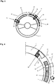
- FIG. 4 Another form of virtual controls shows Fig. 4 .
- the steering wheel 1 is shown there in a partial representation and has a first rectangular virtual control element 37 and a second rectangular virtual control element 38 in the upper region.
- These two control elements 37, 38 are operated with the thumb 14 'of the right hand in such a way that the driver with the thumb 14' along the directional arrow 41 either sweeps the control elements 37, 38 in this order or in the opposite order.
- the thumb 14 'therefore executes a movement which largely corresponds to the movement when operating a scroll wheel. In this way, for example, a screen list can be scrolled from left to right or from right to left.
- the character of the scroll wheel of the above-mentioned virtual control elements can be underlined by the fact that the markings projected onto or firmly arranged on the steering wheel have the appearance and / or feel of a real scroll wheel.
- Fig. 4 The above in connection with Fig. 4 The form of operation described by means of a movement is of course not mandatory for the method according to the invention. It is equally conceivable to use these controls with a static gesture.
- the driver touches one of the virtual operating elements 37, 38, 39, 40 with the thumb 14 ', 14 "of his right hand until, for example, an acknowledgment tone is emitted via a loudspeaker, which corresponds to a switching step.
- the thumb remains in the ingested Position, another switching step is carried out after the next acknowledgment tone.
- a switching step can consist, for example, of moving an indicator (cursor) on a display one step further through a list or also of changing a parameter of a function by one step. If the selection shown on a display is to be accepted, it is sufficient to take your thumb off the virtual control element. Alternatively, the selection can of course also be confirmed by briefly tapping it once or several times.
- the arrangement behaves in accordance with Fig. 4 like a so-called control pad, i.e. like a rocker switch that can be operated in four mutually perpendicular directions.
Landscapes
- Engineering & Computer Science (AREA)
- General Engineering & Computer Science (AREA)
- Theoretical Computer Science (AREA)
- Human Computer Interaction (AREA)
- Physics & Mathematics (AREA)
- General Physics & Mathematics (AREA)
- Multimedia (AREA)
- User Interface Of Digital Computer (AREA)
- Steering Controls (AREA)
Description
Gegenstand der Erfindung ist ein Verfahren zum Steuern von Funktionen eines Kraftfahrzeugs oder darin enthaltener Aggregate, bei dem die Bewegung der Hand und/oder der Finger und/oder des Daumens mittels einer in der Umgebung des Lenkrades angeordneten Sensoreinheit erfasst wird und bei Korrelation der Bewegungen mit vordefinierten Bewegungen, dies als eine Betätigung wenigstens eines virtuellen, real aber nicht vorhandenen Bedienelements gewertet wird. Weiter gehört es zur Erfindung, eine Anordnung zur Durchführung des Verfahrens anzugeben.The invention relates to a method for controlling functions of a motor vehicle or units contained therein, in which the movement of the hand and / or the fingers and / or the thumb is detected by means of a sensor unit arranged in the vicinity of the steering wheel, and when the movements are correlated with predefined movements, this is evaluated as an actuation of at least one virtual, real but not existing control element. It is also part of the invention to provide an arrangement for performing the method.
In Kraftfahrzeugen, insbesondere in Nutzfahrzeugen ist es heute üblich, eine Vielzahl von Funktionen vorzusehen, die notwendigerweise durch Eingaben des Fahrers aktiviert, deaktiviert oder in ihren Parametern verändert werden müssen. Solche Funktionen sind beispielsweise Komfortfunktionen wie Klimaanlage, Sitzverstellung, Lenkradverstellung oder Multimediafunktionen, wie das Einstellen von Radiosendern, das Abspielen von gespeicherten Sprach- oder Musikinhalten oder Navigationsfunktionen, wie das Eingeben von anzufahrenden Zielen, das Aktivieren von Suchfunktionen, zum Beispiel um Tankstellen zu finden. Die vorstehende Aufzählung ist nur beispielhaft zu verstehen, es sind selbstverständlich sehr viele weitere hier nicht genannte Funktionen denkbar, die vom Fahrer einzustellen und/ oder deren Einstellparameter zu verändern sind.In motor vehicles, in particular in commercial vehicles, it is common today to provide a large number of functions which must necessarily be activated, deactivated or their parameters changed by driver input. Such functions are, for example, comfort functions such as air conditioning, seat adjustment, steering wheel adjustment or multimedia functions, such as the setting of radio stations, playing stored voice or music content or navigation functions, such as entering destinations to be reached, activating search functions, for example to find petrol stations. The above list is only to be understood as an example; of course, many other functions not mentioned here are conceivable, which are to be set by the driver and / or whose setting parameters are to be changed.
In der Vergangenheit wurden für solche Aktivierung- bzw. Einstellaufgaben real vorhandene Einstellelemente wie Schalter, Drehknöpfe, Taster, Steuerkreuze, Scroll-Räder, Scroll-Bänder und vieles mehr verwendet. Bei der heute üblichen Vielzahl von Funktionen und Einstellparametern ist es nicht mehr möglich, alle diese Schaltelemente vernünftig in einem Kraftfahrzeug unterzubringen. Es wurde deshalb bereits vorgeschlagen, Funktionen und Einstellparameter über auf einem Bildschirm dargestellte Menüs auszuwählen und dafür nur ein gemeinsames Eingabeelement, wie ein Steuerkreuz, ein Scroll-Rad mit Tastfunktion oder einen berührungsempfindlichen Bildschirm zu verwenden. Solche Anordnungen sind bereits serienmäßig verfügbar und bedürfen keiner näheren Erläuterung.In the past, actually existing setting elements such as switches, rotary knobs, buttons, control crosses, scroll wheels, scroll bands and much more were used for such activation or setting tasks. With the multitude of functions and setting parameters common today, it is no longer possible to reasonably accommodate all of these switching elements in a motor vehicle. It has therefore already been proposed to select functions and setting parameters via menus displayed on a screen and to use only a common input element, such as a directional pad, a scroll wheel with a key function or a touch-sensitive screen. Such arrangements are already available as standard and require no further explanation.
Ein anderer Weg die angesprochene Vielzahl von einstellbaren Funktionen und Einstellparametern zu bewältigen wird mit der sogenannten Gestenerkennung beschritten. Eine derartige Anordnung bzw. ein derartiges Verfahren ist unter der Bezeichnung Handzeichen-Schaltvorrichtung in der
Problematisch ist bei den vorstehend genannten Anordnungen und Verfahren, das einerseits zur Gesteneingabe die Hand des Fahrers vom Lenkrad genommen werden muss (
Das Dokument
Aufgabe der Erfindung ist es, unter Vermeidung der vorstehend angesprochenen Nachteile bereits vorhandener Verfahren und Anordnungen ein Verfahren und eine Anordnung anzugeben, die bei minimalem Aufwand für die Erkennung der Geste und minimalen Aufwand für das Erlernen der durch den Fahrer auszuführenden Gesten eine sichere gestengestützte Auswahl von Funktionen und eine sichere Parametereinstellung durch den Fahrer eines Kraftfahrzeugs insbesondere Nutzfahrzeugs erlaubt ohne die Verkehrssicherheit negativ zu beeinflussen.The object of the invention is to provide a method and an arrangement which avoids the disadvantages of already existing methods and arrangements mentioned above and which, with minimal effort for recognizing the gesture and minimal effort for learning the gestures to be carried out by the driver, makes a safe gesture-based selection of Functions and safe parameter setting by the driver of a motor vehicle, in particular commercial vehicle, are permitted without negatively influencing traffic safety.
Gelöst wird die Aufgabe durch die kennzeichnenden Merkmale eines Verfahrens gemäß Anspruch 1 und die kennzeichnenden Merkmale einer Anordnung gemäß Anspruch besonders vorteilhafte Weiterbildungen sind in den jeweils abhängigen Ansprüchen gekennzeichnet.The object is achieved by the characterizing features of a method according to
Bei der Lösung der Aufgabe wurde von der Überlegung ausgegangen, dass die zu erkennenden Bewegungen bzw. Gesten einerseits in Kontakt mit einem realen das heißt physisch vorhandenen Gegenstand ausgeführt werden und andererseits der Betätigungsbewegung eines realen Eingabeelementes nachgebildet sind. Die Vorteile einer solchen Lösung liegen auf der Hand. Dadurch, dass Gesten bzw. Bewegungen in Kontakt mit einem realen das heißt physisch vorhandenen Gegenstand ausgeführt werden, ist die Variationsbreite gleicher Gesten bzw. Bewegungen sehr gering, da bei der Ausführung der Geste bzw. Bewegung gewissermaßen eine Führung durch den realen Gegenstand gegeben ist. Die Beschränkung auf Bewegungen die einer Betätigungsbewegung eines realen Bedienelementes nachgebildet sind, reduziert die Gesten auf ein minimales Maß und erlaubt ein intuitives Erlernen durch den Fahrer.When solving the task, it was assumed that the movements or gestures to be recognized are carried out on the one hand in contact with a real, that is to say physically present, object and, on the other hand, the actuation movement of a real input element is simulated. The advantages of such a solution are obvious. Because gestures or movements are carried out in contact with a real, that is to say physically present, object, the range of variation of the same gestures or movements is very small, since the execution of the gesture or movement provides guidance to a certain extent through the real object. The restriction to movements that simulate an actuation movement of a real control element reduces the gestures to a minimum and allows the driver to learn intuitively.
Im Vorstehenden wie auch nachfolgend werden die Begriffe "Bewegung" und "Geste" verwendet, gemeint ist damit im Falle von Bewegungen ein dynamischer Vorgang, im Falle von Gesten ein statischer Vorgang. Wenn also nachfolgend von Bewegung der Hand und/oder der Finger und/oder des Daumens die Rede so handelt es sich um eine dynamische Bewegungen, ist von einer Gesten der Hand und/oder der Finger und/oder des Daumens die Rede ist, so soll darunter verstanden werden, dass es sich um einen statischen Vorgang handelt, also eine bestimmte statische Hand-, Finger- oder Daumenhaltung als Betätigungsinformation für das virtuelle Bedienelement dient.In the foregoing and in the following, the terms "movement" and "gesture" are used, meaning in the case of movements a dynamic process, in the case of gestures a static process. So if subsequently the movement of the hand and / or the fingers and / or the thumb is referred to, then it is a matter of dynamic movements, if the gestures of the hand and / or the fingers and / or the thumb are mentioned, then it should are understood to mean that it is a static process, that is, a certain static hand, finger or thumb posture serves as actuation information for the virtual control element.
Für das erfindungsgemäße Verfahren hat es sich als besonders vorteilhaft erwiesen, dass das wenigstens eine virtuelle Bedienelement am Lenkrad definiert ist, und dass mittels der auf das Lenkrad gerichteten Sensoreinheit und einer Auswerteeinheit die Bewegungen bzw. Gesten in Verbindung mit dem Lenkrad ausgewertet werden. Zu diesem Zweck erfasst die Sensoreinheit in wenigstens einem am Lenkrad vordefinierten Bereich Bewegung bzw. Gesten der Hand und/oder der Finger und/oder des Daumens und leitet diese an eine Auswerteeinheit weiter. Unter dem Begriff Sensoreinheit wird dabei ganz allgemein jede Art von Sensor verstanden, der geeignet ist die angesprochenen Bewegungen bzw. Geste zu erfassen. Insbesondere kann es sich um eine oder mehrere Mono- oder Stereokameras, Infrarotsensoren, Ultraschallsensoren, Radarsensoren handeln. Derartige Sensoranordnungen sind im Stand der Technik allgemein bekannt, so dass sich eine ausführliche Beschreibung erübrigt.It has proven particularly advantageous for the method according to the invention that the at least one virtual control element is defined on the steering wheel and that the movements or gestures in connection with the steering wheel are evaluated by means of the sensor unit directed at the steering wheel and an evaluation unit. For this purpose, the sensor unit detects movement or gestures of the hand and / or the fingers and / or the thumb in at least one area predefined on the steering wheel and forwards them to an evaluation unit. The term sensor unit is generally understood to mean any type of sensor that is suitable for detecting the movements or gesture mentioned. In particular, it can be one or more mono or stereo cameras, infrared sensors, Act ultrasonic sensors, radar sensors. Such sensor arrangements are generally known in the prior art, so that a detailed description is unnecessary.
Die Auswerteeinheit, an die die Sensoreinheit die erfassten Bewegungen bzw. Geste weiterleitet, überprüft, ob die fraglichen Bewegung bzw. Geste relativ zum Lenkrad in einem vordefinierten Bereich des Lenkrades ausgeführt wurden. Ist dies der Fall, vergleicht die Auswerteeinheit die erfasste Bewegungen bzw. Geste mit wenigstens einem vordefinierten gespeicherten Muster. Wird bei diesem Vergleich Übereinstimmung mit dem wenigstens einen Muster festgestellt, löst die Auswerteeinheit einen vordefinierten Schaltschritt aus. Bei der Auswerteeinheit handelt es sich, wie in solchen Fällen üblich, um ein auf einem Computer implementiertes Programm, das die Steuerschritte Datenübernahme von der Sensoreinheit, Feststellung ob eine Bewegung bzw. Geste relativ zum Lenkrad in einem vordefinierten Bereich des Lenkrades ausgeführt wurde, Vergleich der Bewegung bzw. Geste mit gespeicherten Mustern und Auslösen eines Schaltschrittes nacheinander ausführt.The evaluation unit, to which the sensor unit forwards the detected movements or gesture, checks whether the movement or gesture in question was carried out relative to the steering wheel in a predefined area of the steering wheel. If this is the case, the evaluation unit compares the detected movements or gestures with at least one predefined stored pattern. If agreement is found in this comparison with the at least one pattern, the evaluation unit triggers a predefined switching step. The evaluation unit, as is customary in such cases, is a program implemented on a computer that performs the control steps of data transfer from the sensor unit, determination of whether a movement or gesture relative to the steering wheel was carried out in a predefined area of the steering wheel, comparison of the Movement or gesture with saved patterns and triggering a switching step in succession.
Um die Auswertung von Bewegungen bzw. Gesten zu vereinfachen und so den apparativen Aufwand zu minimieren ist es von Vorteil, die Sensoreinheit so auszubilden, dass diese eine Information an die Auswerteeinheit liefert, ob die Hand und/oder der Finger und/oder der Daumen im vordefinierten Bereich zu dem Lenkrad ist und dass die Auswerteeinheit im Falle, dass die Hand und/oder der Finger und/oder der Daumen im Bereich zu dem Lenkrad ist, relativ zum Lenkrad ausgeführte erfasste Bewegungen bzw. Geste mit wenigstens einem vordefinierten gespeicherten Muster vergleicht. Dies kann dadurch geschehen, dass die Sensoreinheit nur den relevanten Bereich des Lenkrades zum Beispiel aus unterschiedlichen Richtungen erfasst, derart, dass klar unterscheidbar ist, dass sich die Hand und/oder der Finger und/oder der Daumen im fraglichen Bereich zu dem Lenkrad befinden.In order to simplify the evaluation of movements or gestures and thus to minimize the expenditure on equipment, it is advantageous to design the sensor unit in such a way that it provides the evaluation unit with information as to whether the hand and / or the fingers and / or the thumb in the predefined area to the steering wheel and that the evaluation unit, in the event that the hand and / or the finger and / or the thumb is in the area to the steering wheel, compares detected movements or gestures carried out relative to the steering wheel with at least one predefined stored pattern. This can be done in that the sensor unit only detects the relevant area of the steering wheel, for example from different directions, in such a way that it can be clearly distinguished that the hand and / or the finger and / or the thumb are in the area in question to the steering wheel.
Alternativ besteht die Möglichkeit, einen separaten Sensor vorzusehen, der eine Information an die Auswerteeinheit liefert, ob die Hand und/oder der Finger und/oder der Daumen im vordefinierten Bereich zu dem Lenkrad ist. Dabei kann es sich zum Beispiel um eine Kontaktsensor, zum Beispiel einen kapazitiven Sensor handeln, der eine Information an die Auswerteeinheit liefert, dass die Hand und/oder der Finger und/oder der Daumen im vordefinierten Kontaktbereich zu dem Lenkrad ist. Ein solcher Kontaktsensor vereinfacht die Sensoreinheit vorteilhaft, weil die Erfassung der Bewegung bzw. Geste der Hände und/oder der Finger und/oder der Daumen nur aus einem Blickwinkel erforderlich ist. Selbstverständlich besteht alternativ hierzu die Möglichkeit eine automatische Entfernungsmessung zu dem Daumen (dem Finger, der Hand) durchzuführen, der die Bewegung oder Geste ausführt. Entsprechende Ultraschall-, Laser- oder Radarmesseinrichtungen sind bekannt.Alternatively, there is the possibility of providing a separate sensor which supplies the evaluation unit with information as to whether the hand and / or the finger and / or the thumb is in the predefined area with respect to the steering wheel. This can be, for example, a contact sensor, for example a capacitive sensor, which supplies the evaluation unit with information that the hand and / or the finger and / or the thumb is in the predefined contact area with the steering wheel. Such a contact sensor advantageously simplifies the sensor unit because the movement or gesture of the hands and / or the fingers and / or the thumbs is only required to be recorded from one angle. Of course alternatively, there is the possibility of performing an automatic distance measurement to the thumb (the finger, the hand) that carries out the movement or gesture. Corresponding ultrasound, laser or radar measuring devices are known.
Um den wenigstens einen am Lenkrad vordefinierten Bereich vom übrigen Lenkrad unterscheidbar zu machen ist es vorteilhaft, diesen als haptisch und/ oder visuell unterscheidbare Markierung auszubilden. Dabei kann die haptische Unterscheidbarkeit vorteilhaft durch fühlbare Einkerbungen und/ oder Muster und/ oder Materialunterschiede erreicht werden. Für die visuelle Unterscheidbarkeit ist es von Vorteil, die Markierung durch sichtbare Kontur und/ oder Muster und/ oder Farbmarkierungen zu bilden. Besonders vorteilhaft ist eine Kombination aus haptischer und visueller Unterscheidbarkeit, indem fühlbare Merkmale mit sichtbaren Merkmalen kombiniert werden.In order to make the at least one area predefined on the steering wheel distinguishable from the rest of the steering wheel, it is advantageous to design it as a haptically and / or visually distinguishable marking. The haptic differentiation can advantageously be achieved through notches and / or patterns and / or material differences. For visual differentiation, it is advantageous to form the marking using a visible contour and / or pattern and / or color markings. A combination of haptic and visual differentiability is particularly advantageous in that tactile features are combined with visible features.
Um die Bewegungs- bzw. Gestenerfassung weiter zu vereinfachen und den Fahrer von Überlegungen zu befreien, wo am Lenkrad die Bewegungen bzw. Gesten auszuführen sind, ist es vorteilhaft, den wenigstens einen am Lenkrad vordefinierten Bereich unabhängig vom Lenkeinschlag des Lenkrades festzulegen, derart, dass dieser bei Lenkeinschlägen an der Stelle verharrt, die er bei Geradeausfahrstellung des Lenkrades einnimmt.In order to further simplify the movement or gesture detection and to free the driver from considerations as to where the movements or gestures are to be carried out on the steering wheel, it is advantageous to define the at least one area predefined on the steering wheel independently of the steering angle of the steering wheel in such a way that this remains at the steering angle at the point it occupies when the steering wheel is in the straight ahead driving position.
Weiter besteht vorteilhaft die Möglichkeit, den wenigstens einen am Lenkrad vordefinierten Bereich durch Aufprojizieren einer Lichtmarkierung sichtbar zu machen. Hierzu bietet sich jede Art von Lichtquelle an, die eine visuell wahrnehmbare Lichtmarke erzeugt. Eine solche Vorgehensweise erleichtert es dem Fahrer erheblich, die Bewegung bzw. Geste an der richtigen Stelle relativ zum Lenkrad auszuführen, so dass dessen Aufmerksamkeit nicht unnötig vom Verkehrsgeschehen abgelenkt wird. Projektionseinrichtungen der angesprochenen Art sind zum Beispiel aus Anwendungen mit sogenannten Haed-Up-Displays bekannt, auch in vielen anderen technischen Bereichen werden Projektionseinrichtungen verwendet, so dass sich eine ausführliche Beschreibung solcher Projektionseinrichtungen erübrigt.Furthermore, there is advantageously the possibility of making the at least one area predefined on the steering wheel visible by projecting on a light marking. Any type of light source that generates a visually perceptible light mark is suitable for this. Such a procedure makes it considerably easier for the driver to execute the movement or gesture in the correct position relative to the steering wheel, so that its attention is not unnecessarily distracted from the traffic situation. Projection devices of the type mentioned are known, for example, from applications with so-called haed-up displays, projection devices are also used in many other technical fields, so that a detailed description of such projection devices is unnecessary.
Weiter ist es von Vorteil, wenn die Lichtmarkierung die Kontur eines realen Bedienelementes aufweist. Damit wird erreicht, dass unterschiedliche Arten von Bedienelementen dargestellt werden können, was in vorteilhafter Weise dem Fahrer die Art der auszuführenden Geste bzw. Bewegung bereits durch die Art des dargestellten Bedienelementes suggeriert, so dass der Lernaufwand für den Fahrer und der Aufwand für die Erkennung der Bewegung bzw. Geste vorteilhaft minimiert werden.It is also advantageous if the light marking has the contour of a real control element. This ensures that different types of control elements can be displayed, which in an advantageous manner already suggests to the driver the type of gesture or movement to be carried out by the type of control element shown, so that the learning effort for the driver and the effort for recognizing the Movement or gesture can advantageously be minimized.
Besonders einfach bedienbar sind bekanntermaßen sogenannte Scroll-Räder, es ist daher von besonderem Vorteil, wenn die Lichtmarkierung die Kontur eines Scroll-Rades aufweist und die gespeicherten Bewegungsmuster den Bewegungen bei der Bedienung eines realen Scroll-Rades entsprechen. Es wird so vorteilhaft erreicht, dass der Fahrer bei der Bedienung intuitiv auf ihm bekannte Bewegungsmuster zurückgreift und die Bewegungs- bzw. Gestenerkennung vorteilhaft auf diese einfachen, gut unterscheidbaren Bewegungen bzw. Gesten beschränkt werden kann.As is known, so-called scroll wheels are particularly easy to use, so it is particularly advantageous if the light marking has the contour of a scroll wheel and the stored movement patterns correspond to the movements when operating a real scroll wheel. It is advantageously achieved that the driver intuitively uses movement patterns known to him during operation and the movement or gesture recognition can advantageously be limited to these simple, clearly distinguishable movements or gestures.
Um durch Lenkbewegungen bedingte Bewegungen der Finger und/ oder Hände und/ oder Daumen nicht irrtümlich als Bewegungen bzw. Gesten bei der Auswahl von Funktionen oder Parameter auszuwerten ist es vorteilhaft, das Verfahren so zu gestalten, dass die Auswerteeinheit nur Muster auswertet, wenn der Lenkwinkel und/ oder die Lenkwinkeländerung pro Zeiteinheit unter einem vorgegebenen Schwellenwert liegt. Hierzu wird zum Beispiel ein Lenkwinkelsensor verwendet, der mit der Auswerteeinheit wirkverbunden ist, so dass diese eine Auswertung von Gesten bzw. Bewegungen unterdrücken kann, wenn der Lenkwinkel und/ oder die Lenkwinkeländerung pro Zeiteinheit einen vorgegebenen Schwellenwert übersteigt. Als Lenkwinkelsensoren kommen alle Arten von Drehwinkelgebern in Frage, gleich nach welchem physikalischen Prinzip (zum Beispiel induktiv, kapazitiv, optisch, Hall-Effekt) diese arbeiten. Besonders vorteilhaft sind digitale Drehwinkelgeber, deren Ausgangssignal von der Auswerteeinheit direkt auswertbar ist.In order not to erroneously evaluate movements of the fingers and / or hands and / or thumbs caused by steering movements as movements or gestures when selecting functions or parameters, it is advantageous to design the method in such a way that the evaluation unit only evaluates patterns when the steering angle and / or the steering angle change per unit of time is below a predetermined threshold value. For this purpose, for example, a steering angle sensor is used, which is operatively connected to the evaluation unit, so that it can suppress an evaluation of gestures or movements if the steering angle and / or the steering angle change per unit time exceeds a predetermined threshold value. All types of rotary angle sensors can be used as steering angle sensors, regardless of the physical principle (for example inductive, capacitive, optical, Hall effect) they work. Digital rotary angle transmitters whose output signal can be evaluated directly by the evaluation unit are particularly advantageous.
Um dem Fahrer eine Rückmeldung über das erfolgreiche Bedienen des virtuellen Bedienelementes zu geben ist es von Vorteil, wenn eine mit der Auswerteeinheit wirkverbundene Feedback-Einheit vorgesehen ist, die bei Auslösen eines Schaltschrittes eine akustische und/ oder eine optische und/ oder eine haptische Rückmeldung abgibt.In order to provide the driver with feedback about the successful operation of the virtual control element, it is advantageous if a feedback unit which is operatively connected to the evaluation unit is provided and which emits an acoustic and / or an optical and / or a haptic feedback when a switching step is triggered .
Für die Auswertung der Bewegungen bzw. Gesten ist es vorteilhaft, diese anhand ihrer Startposition und/ oder Bewegungsrichtung und/ oder Bewegungsgeschwindigkeit und/ oder Änderung der Bewegungsgeschwindigkeit und/ oder Endposition und/ oder Form zu identifizieren.For the evaluation of the movements or gestures, it is advantageous to identify them on the basis of their start position and / or direction of movement and / or movement speed and / or change in the movement speed and / or end position and / or shape.
Weiter ist es von Vorteil, die Auswertung der relativ zum Lenkrad ausgeführten Bewegung bzw. Geste durch eine Eingangsgeste bzw. Bewegung und/ oder eine akustische Eingabe zu starten. Auf diese Weise wird der die Bewegungs- bzw. Gestenerkennung durchführende Rechner weniger belastet. Im Falle von Eingangsgesten bzw. Bewegungen muss zunächst nur auf eine spezifischen Geste bzw. Bewegung hin überwacht werden und erst nach deren Erkennung auf eine Mehrzahl von Bewegungen bzw. Gesten hin. Im Falle einer akustischen Starteingabe ist die Gesten- bzw. Bewegungserkennung nur nach dieser und nur für einen begrenzten Zeitraum aktiviert. In beiden Fällen wird Rechenleistung eingespart.It is also advantageous to start the evaluation of the movement or gesture carried out relative to the steering wheel by an input gesture or movement and / or an acoustic input. In this way, the person who performs the movement or gesture recognition Computer less burdened. In the case of input gestures or movements, only a specific gesture or movement needs to be monitored first and only after they have been recognized for a plurality of movements or gestures. In the case of an acoustic start input, gesture or motion detection is only activated after this and only for a limited period of time. Computing power is saved in both cases.
Zur Durchführung des Verfahrens ist es vorteilhaft, wenigstens eine auf das Lenkrad gerichtete Sensoreinheit vorzusehen, die aus einem oder mehreren Sensoren bestehen kann. Als Sensoren kommen alle Anordnungen in Frage, die in der Lage sind Bewegungen oder Gesten aus der Distanz zu erfassen. Darunter fallen sowohl Einzelsensoren wie Sensorarrays, die, wie bereits oben erwähnt, nach unterschiedlichen physikalischen Prinzipien arbeiten können. Es sind sowohl Bildaufnehmer, wie sie in Kameras verwendet werden, als auch akustische Sensoren, insbesondere Ultraschallsensoren, optische Sensoren insbesondere Infrarotsensoren oder Radarsensoren denkbar.To carry out the method, it is advantageous to provide at least one sensor unit directed towards the steering wheel, which can consist of one or more sensors. All arrangements that are able to detect movements or gestures from a distance can be used as sensors. This includes both individual sensors and sensor arrays, which, as already mentioned above, can work according to different physical principles. Both image recorders as used in cameras and acoustic sensors, in particular ultrasound sensors, optical sensors, in particular infrared sensors or radar sensors, are conceivable.
Für die Auswertung der durch die Sensoreinheit erfassten Bewegungen bzw. Gesten ist vorteilhaft eine Auswerteeinheit vorgesehen, die Bewegung bzw. Gesten der Hand und/oder der Finger und/oder des Daumens in Verbindung mit dem Lenkrad auswertet. Nach dem heutigen Stand der Technik wird eine solche Auswerteeinheit üblicherweise als Steuerroutine programmgestützt auf einer Recheneinheit ausgeführt, die in heute üblichen Kraftfahrzeugen insbesondere Nutzfahrzeugen bereits enthalten ist.For the evaluation of the movements or gestures detected by the sensor unit, an evaluation unit is advantageously provided which evaluates movements or gestures of the hand and / or the fingers and / or the thumb in connection with the steering wheel. According to the current state of the art, such an evaluation unit is usually executed as a program-based control routine on a computing unit that is already contained in today's common motor vehicles, particularly commercial vehicles.
Die Sensoreinheit und die Auswerteeinheit sind wirkverbunden, so dass die durch die Sensoreinheit erfassten Bewegungen bzw. Gesten von der Auswerteeinheit übernommen und analysiert werden. Bei der Analyse der Gesten bzw. Bewegungen wird vorteilhaft so vorgegangen, dass die Auswerteeinheit relativ zum Lenkrad ausgeführte erfasste Muster von der Geste bzw. Bewegung mit wenigstens einem vordefinierten gespeicherten Muster vergleicht. Wird bei dieser Analyse eine Übereinstimmung festgestellt, löst die Auswerteeinheit einen dieser Bewegung bzw. Geste zugeordneten vordefinierten Schaltschritt aus.The sensor unit and the evaluation unit are operatively connected, so that the movements or gestures detected by the sensor unit are adopted and analyzed by the evaluation unit. When analyzing the gestures or movements, the procedure is advantageously such that the evaluation unit compares detected patterns of the gesture or movement executed relative to the steering wheel with at least one predefined stored pattern. If a match is found during this analysis, the evaluation unit triggers a predefined switching step assigned to this movement or gesture.
In besonders vorteilhafter Weiterbildung der Anordnung kann, wie bereits oben ausgeführt, eine Feedback-Einheit mit der Auswerteeinrichtung verbunden sein. Diese Rückmeldeeinrichtung kann so ausgebildet sein, dass bei der Ausführung eines einer erkannten Bewegung bzw. Geste zugeordneten Schaltschrittes durch die Auswerteeinheit, diese ein Ausgangssignal an die Feedback-Einheit abgibt, wodurch diese ihrerseits ein optisches und/ oder akustisches und/ oder haptisches Signal erzeugt. Bei dem optischen Signal kann es sich um ein Lichtsignal handeln, das besonders vorteilhaft durch die oben erwähnte Projektionseinheit erzeugt wird oder den Wechsel der Darstellung auf einer Anzeige. Selbstverständlich kann auch eine akustische Signalgabe erfolgen, die je nach ausgeführtem Schaltschritt in Frequenz, Länge, Tonfolge unterschiedlich sein kann. Auch eine Sprachausgabe kann in diesem Zusammenhang besonders vorteilhaft sein. Alternativ oder ergänzend ist auch eine haptische Signalgabe denkbar, zum Beispiel indem das Lenkrad und/ oder der Fahrersitz vibriert, wenn der Schaltschritt ausgeführt ist.In a particularly advantageous development of the arrangement, as already explained above, a feedback unit can be connected to the evaluation device. This feedback device can be designed in such a way that when a switching step associated with a detected movement or gesture is carried out by the evaluation unit, the latter outputs an output signal to the feedback unit, which in turn produces an optical and / or acoustic signal and / or haptic signal generated. The optical signal can be a light signal which is generated particularly advantageously by the above-mentioned projection unit or the change in the representation on a display. Of course, an acoustic signal can also be given, which can vary in frequency, length, tone sequence depending on the switching step carried out. A voice output can also be particularly advantageous in this context. Alternatively or in addition, haptic signaling is also conceivable, for example in that the steering wheel and / or the driver's seat vibrates when the switching step is carried out.
Ist der Schaltschritt ein Scrollen durch ein Menü oder eine Parameterauswahl aus einem Menü, wird natürlich als optisches Signal die Darstellung einer alphanumerischen Anzeige auf einem Bildschirm oder einem Head-Up-Display wechseln, hier ist es sinnvoll und damit vorteilhaft, einen Schaltschritt ergänzend durch ein Tonsignal zu quittieren.If the switching step is a scrolling through a menu or a parameter selection from a menu, the display of an alphanumeric display on a screen or a head-up display will of course change as an optical signal; here it makes sense and is therefore advantageous to supplement a switching step with a Acknowledge audio signal.
Das vorstehend beschriebene Verfahren, sowie die beschriebene Anordnung lassen sich vorteilhaft allgemein in Fahrzeugen, insbesondere auch in Nutzfahrzeugen einsetzen. Weitere Ausgestaltungen und Vorteile der Erfindung werden nachfolgend anhand der Zeichnungen näher erläutert, es zeigen:
- Fig. 1
- Eine Prinzipdarstellung einer Anordnung zur Durchführung des Verfahrens zum Steuern von Funktionen eines Kraftfahrzeugs
- Fig. 2
- Ein Beispiel zur Auswahl von Funktionen bzw. Parametern
- Fig. 3
- Ein erstes Beispiel für virtuelle Bedienelemente
- Fig. 4
- Ein zweites Beispiel für virtuelle Bedienelemente
- Fig. 1
- A schematic representation of an arrangement for performing the method for controlling functions of a motor vehicle
- Fig. 2
- An example for the selection of functions or parameters
- Fig. 3
- A first example of virtual controls
- Fig. 4
- A second example of virtual controls
In der Prinzipdarstellung gemäß
Zu den vorstehend angesprochenen Komponenten Auswerteeinheit 3 und Feedback-Einheit 5 ist anzumerken, dass es sich hier nicht um abgrenzbare Hardwareeinheiten handelt, sondern vielmehr um Funktionseinheiten, die durch Programme realisiert sind, die ihrerseits auf einer Recheneinheit implementiert sind.Regarding the above-mentioned components evaluation unit 3 and
Um nun die Funktionsweise der in
In Verbindung mit dem Beispiel gemäß
Um nun die Komponente Radio auszuwählen, ist in dem vorliegenden Beispiel vorgesehen, dass der rechte Daumen 14 des Fahrers in der zuletzt eingenommenen Position verharrt bis eine taktile Rückmeldung in der Weise erfolgt, dass die Auswerteeinheit 3 über die Feedback Einheit 5 das Vibratorelement 18 ansteuert und so das Lenkrad 1 in Schwingungen versetzt, die von einem Tonsignal aus dem Lautsprecher 17 begleitet wird. Mit Auswahl der Komponente "Radio" verschwindet das Hauptmenü 21 von der Anzeige und es wird das erste Untermenü 22 dargestellt. Wie bereits erwähnt, beinhaltet das erste Untermenü 22 eine Funktionen-Liste und einen Pfeil als Indikator, der in der dritten Pfeilposition 28 der aktuell ausgewählten Funktion "Sender", die für die Sendereinstellung steht, gegenüber dargestellt ist. Um nun zur Funktion "Lautstärke" zu gelangen bringt der Fahrer seinen Daumen 14 in den oberen Bereich des ersten virtuellen Bedienelementes 12 oder bewegt den Daumen 14 alternativ von dem unteren Bereich des ersten virtuellen Bedienelementes 12 in dessen oberen Bereich. Auch diese Geste bzw. Bewegung wird über die erste Kamera 8 an die Auswerteeinheit 3 übermittelt, von dieser mit in dem Speicher 16 vorgehaltenen Mustern verglichen und bei festgestellter Übereinstimmung mit einem solchen Muster der zugehörige Schallschritt ausgelöst. Im vorliegenden Fall verschiebt der ausgelöste Schaltschritt den pfeilförmigen Indikator in dem ersten Untermenü 22 um einen Schritt nach oben, so dass dieser nun in der Pfeilposition 29 der Funktion "Lautstärke" gegenübersteht. Da es sich um die gewünschte Funktion handelt, verbleibt der Fahrer mit den rechten Daumen 14 in der zuletzt eingenommenen Positionen, so dass nach Verstreichen einer vorgegebenen Zeit die Farbe des Pfeils in der Anzeige von hell nach dunkel Wechsel und die Auswerteeinheit 3 über die Feedback-Einheit 5 das Vibratorelement 18 im Lenkrad ansteuert und über den Lautsprecher 17 einen Tonsignal abgibt.In order to select the radio component in the present example, it is provided that the driver's
Abweichend vom vorstehend beschriebenen Beispiel lässt sich natürlich das Auswählen einer Funktion durch ganz unterschiedliche Gesten verwirklichen. An Stelle des Verharrens in der zuletzt eingenommenen Position kann das einmalige oder mehrmalige Antippen des Lenkrades als Auswahl-Geste vorgesehen sein. Insbesondere das Antippen des Lenkradkranzes mit der Hand von außen radial nach innen gerichtet, wie dies durch den Gesten-Pfeil 43 in
Nach erfolgter Auswahl der Funktion "Lautstärke" verschwindet das Untermenü 22 von der Anzeige und es wird stattdessen das zweite Untermenü 23 dargestellt. Mit der Darstellung des zweiten Untermenüs 23 deaktiviert eine nicht dargestellte externe Steuereinheit den ersten Projektor 6 sowie die erste Kamera 8 über die Auswerteeinheit 3 und aktiviert den zweiten Projektor 7 und die zweite Kamera 9. Der aktivierte zweite Projektor 7 projiziert nun das zweite virtuelle Bedienelemente 13 auf das Lenkrad 1. Wie bereits erwähnt, handelt es sich bei dem zweiten Untermenü 23 um eine Lautstärkensanzeige, die auf der linken Lautstärke-Skala 30 vier Lautstärkestufen anzeigt und daneben einen ersten Lautstärke-Indikator 31 der die derzeit eingestellte Lautstärke symbolisiert. Um nun die Lautstärke um eine Stufe zu reduzieren bewegt der Fahrer seinen linken Daumen 15 in den unteren Bereich des auf der linken Seite des Lenkrades 1 angeordneten zweiten virtuellen Bedienelementes 13 oder führt alternativ mit dem linken Daumen 15 eine Bewegung vom oberen Teil des zweiten virtuellen Bedienelementes 13 in den unteren Teil aus. Diese Bewegung oder Geste wird von der zweiten Kammer 9 an die Auswerteeinheit 3 übermittelt, von dieser mit in dem Speicher 16 vorgehaltenen Mustern verglichen und bei Übereinstimmung in einen Schaltschritt übergeführt in der Weise, dass die Lautstärke des Radios um eine Stufe reduziert wird. Dies geschieht sowohl auf der Anzeige indem der zweite Lautstärke-Indikator 32 an Stelle des ersten Lautstärkeindikators 31 dargestellt wird, als auch durch Reduzieren der Lautstärke des Radios um einen Schritt. Hierzu ist es selbstverständlich erforderlich, dass zwischen der Auswerteeinheit 3 und der Steuerung des Radios (nicht dargestellt) eine Wirkverbindung besteht. Diese Wirkverbindung, die notwendig ist um jede Art von Eingabe über ein virtuelles Bedienelement in einen realen Schaltschritt umzusetzen ist in der
Wie oben ausgeführt, befindet sich am Lenkrad 1 bzw. an der Lenksäule ein Lenkwinkelsensor 19 der die Auswertung des aktuellen Lenkwinkels, sowie dessen Änderung pro Zeiteinheit durch die Auswerteinheit 3 gestattet. Übersteigt der Lenkwinkel bzw. dessen zeitliche Änderung einen Grenzwert, unterbricht die Auswerteeinheit 3 einen zu diesem Zeitpunkt laufenden Erfassungsvorgang für die Betätigung eines virtuellen Bedienelementes 12, 13 und gibt über die Feedback-Einheit 5 und den Lautsprecher 6 sowie gegebenenfalls über das Vibrationselement 18 ein Signal aus.As stated above, there is a
Neben den in Verbindung mit
Das in
Selbstverständlich besteht auch die Möglichkeit, ein virtuelles Scroll-Band 44 am Lenkradkranz tangential außen anzuordnen, die Bedienung erfolgt dann nicht mit dem Daumen sondern durch Überstreichen des Lenkradkranzes mit der Hand. Ein so angeordnetes Bedienelement lässt sich durch Aufprojizieren nur schlecht kenntlich machen, es ist daher bei einem so angeordneten virtuellen Scroll-Band sinnvoll, haptisch fühlbare Marken 45 vorzusehen. Diese drehen sich natürlich mit dem Lenkrad 1 mit, was bei der Bedienung zu beachten ist. Die Auswertung der relativ zum virtuellen Scroll-Band 44 ausgeführten Bewegungen erfolgt, wie bei allen ortsfest zum Lenkrad 1 angeordneten virtuellen Bedienelementen, unter Beachtung des Drehwinkels des Lenkrades zum Beispiel in der Weise, dass die die Geste erfassende Kamera unabhängig vom Lenkeinschlag auf den Teil des Lenkrades gerichtet bleibt, der die haptisch fühlbare Marken 45 trägt. Als weitere Möglichkeit lässt sich die Lenkbewegung als überlagerte Bewegung aus der relativ zum Lenkrad ausgeführten Bewegung eliminieren. Zur Lenkwinkelerfassung wird dabei der Lenkwinkelsensor 19 (
Eine weitere Form virtueller Bedienelemente zeigt
Unterstrichen werden kann der Scrollrad-Charakter der vorstehend angesprochenen virtuellen Bedienelemente dadurch, dass die aufprojizierte oder fest auf dem Lenkrad angeordnete Markierung im Aussehen und/ oder Haptik einem realen Scrollrad nachgebildet ist.The character of the scroll wheel of the above-mentioned virtual control elements can be underlined by the fact that the markings projected onto or firmly arranged on the steering wheel have the appearance and / or feel of a real scroll wheel.
Die im vorstehenden in Verbindung mit
In der vorstehend beschriebenen Variante verhält sich die Anordnung gemäß
Selbstverständlich sind die Möglichkeiten, virtuelle Bedienelemente am Lenkrad eines Fahrzeugs vorzusehen, mit den vorstehend aufgezeigten Beispielen nicht ausgeschöpft. Es sind vielmehr vielfältigste Variationen von Bedienelementen denkbar insbesondere ist es vorteilhaft, dass je nach Funktion, der die jeweils auf das Lenkrad projizierten Bedienelemente dienen, deren Form und Anordnung unterschiedlich ist. Gleichfalls kann es vorteilhaft sein, dass Eingriffsmöglichkeiten durch den Fahrer vorgesehen sind, der Gestalt, dass er Einfluss auf die Art der Darstellung und insbesondere auch auf den Ort der Darstellung der virtuellen Bedienelemente auf dem Lenkrad nehmen kann. Hierzu können entsprechende Eingriffsmöglichkeiten an der Projektionseinrichtung vorgesehen sein, die zum Beispiel eine Anpassung an die bevorzugte Handstellung des Fahrers am Lenkrad ermöglichen.Of course, the possibilities of providing virtual control elements on the steering wheel of a vehicle are not exhausted with the examples shown above. Rather, the most varied variations of operating elements are conceivable. In particular, it is advantageous that, depending on the function that the operating elements projected on the steering wheel serve, the shape and arrangement of which are different. Likewise, it can be advantageous for the driver to provide intervention options, in the form that he can influence the type of display and in particular also the location of the virtual control elements on the steering wheel. For this purpose, corresponding intervention options can be provided on the projection device, which, for example, allow adaptation to the preferred hand position of the driver on the steering wheel.
Handelt es sich, wie weiter oben bereits angesprochen, um ortsfest am Lenkrad angeordnete virtuelle Bedienelemente, sind alle Formen von haptisch und/ oder visuell vom übrigen Lenkrad unterscheidbare Markierungen zu deren Kennzeichnung denkbar. Für die haptische Unterscheidbarkeit bieten sich insbesondere durch fühlbare Einkerbungen und/ oder Muster und/ oder Materialunterschiede viele Möglichkeiten der Gestaltung während für die visuelle Unterscheidbarkeit insbesondere sichtbare Kontur und/ oder Muster und/ oder Farbmarkierungen eine Vielzahl von Ausgestaltungsmöglichkeiten eröffnen.If, as already mentioned above, virtual operating elements are arranged in a fixed position on the steering wheel, all forms of markings which can be differentiated haptically and / or visually from the rest of the steering wheel are conceivable for their identification. There are many design options for haptic differentiation, in particular due to tactile notches and / or patterns and / or material differences, while for contouring and / or patterns and / or color markings, in particular, visible contour and / or color markings open up a multitude of design options.
- 11
- Lenkradsteering wheel
- 22nd
- SensoreinheitSensor unit
- 33rd
- AuswerteeinheitEvaluation unit
- 44th
- ProjektionseinheitProjection unit
- 55
- Feedback-EinheitFeedback unit
- 66
- erster Projektorfirst projector
- 77
- zweiter Projektorsecond projector
- 88th
- erste Kamerafirst camera
- 99
- zweite Kamerasecond camera
- 1010th
- erster Erkennungsbereichfirst detection area
- 1111
- zweiter Erkennungsbereichsecond detection area
- 1212th
- erstes virtuelles Bedienelementfirst virtual control element
- 1313
- zweites virtuelles Bedienelementsecond virtual control element
- 1414
- rechter Daumenright thumb
- 1515
- linker Daumenleft thumb
- 1616
- MusterspeicherSample memory
- 1717th
- Lautsprecherspeaker
- 1818th
- VibrationselementVibration element
- 1919th
- LenkwinkelsensorSteering angle sensor
- 2020
- KontaktsensorContact sensor
- 2121
- Hauptmenümain menu
- 2222
- erstes Untermenüfirst submenu
- 2323
- zweites Untermenüsecond submenu
- 2424th
- KomponentenlisteComponent list
- 2525th
- erste Pfeilpositionfirst arrow position
- 2626
- zweite Pfeilpositionsecond arrow position
- 2727
- Funktionen-ListeFeatures list
- 2828
- dritte Pfeilpositionthird arrow position
- 2929
- vierte Pfeilpositionfourth arrow position
- 3030th
- Lautstärke-SkalaVolume scale
- 3131
- erster Lautstärke-Indikatorfirst volume indicator
- 3232
- zweiter Lautstärke-Indikatorsecond volume indicator
- 3333
- erstes langgestrecktes bogenförmiges virtuelles Bedienelementfirst elongated curved virtual control element
- 3434
- zweites langgestrecktes bogenförmiges virtuelles Bedienelementsecond elongated arc-shaped virtual control element
- 3535
- erster Richtungspfeilfirst arrow
- 3636
- zweiter Richtungspfeilsecond arrow
- 3737
- erstes rechteckiges virtuelles Bedienelementfirst rectangular virtual control element
- 3838
- zweites rechteckiges virtuelles Bedienelementsecond rectangular virtual control element
- 3939
- erstes bogenförmiges virtuelles Bedienelementfirst curved virtual control element
- 4040
- zweites bogenförmiges virtuelles Bedienelementsecond curved virtual control element
- 4141
- dritter Richtungspfeilthird directional arrow
- 4242
- vierter Richtungspfeilfourth arrow
- 4343
- Gesten-PfeilGesture arrow
- 4444
- virtuelles Scroll-Bandvirtual scroll band
- 4545
- fühlbare Markentangible brands
Claims (23)
- Method for controlling functions of a motor vehicle or assemblies contained therein, in which the movement or gesture of the hand and/or the fingers and/or the thumb is captured by way of a sensor unit arranged in the vicinity of the steering wheel and, upon correlation of the movements or gestures with predefined movements or gestures, this is evaluated as an actuation of at least one virtual operating element that is real yet not present, characterized in that the at least one virtual operating element (12, 13, 33, 34, 37, 38, 38, 40) is defined on the steering wheel (1) and in that the movement or gestures are evaluated in connection with the steering wheel (1) by way of the sensor unit (2), which is directed at the steering wheel (1), and an evaluation unit (3) such that- the sensor unit (2) captures movements or gestures of the hand and/or the fingers and/or the thumb that are performed in contact with the real steering wheel in at least one region predefined on the steering wheel (1) and passes them on to an evaluation unit (3),- the evaluation unit (3) compares captured movements or gestures performed relative to the steering wheel (1) to at least one predefined stored pattern and- the evaluation unit (3) triggers a predefined switching step in the case of a predefined match to the at least one pattern.
- Method according to Claim 1, characterized in that the sensor unit (2) provides information to the evaluation unit (3) relating to whether the hand and/or the finger and/or the thumb is located in the predefined region with respect to the steering wheel (1) and in that, if the hand and/or the finger and/or the thumb is located in the region with respect to the steering wheel (1), the evaluation unit (3) compares captured movements or gestures performed relative to the steering wheel (1) to at least one predefined stored pattern.
- Method according to Claim 1, characterized in that a separate contact sensor (20) provides information to the evaluation unit (3) relating to whether the hand and/or the finger and/or the thumb is located in the predefined contact region with respect to the steering wheel (1) and in that, if the hand and/or the finger and/or the thumb is located in the contact region with respect to the steering wheel (1), the evaluation unit (3) compares captured movements or gestures performed relative to the steering wheel (1) to at least one predefined stored pattern.
- Method according to Claim 1, characterized in that the at least one region predefined on the steering wheel (1) is embodied as a mark that is able to be differentiated haptically and/or visually from the remaining steering wheel.
- Method according to Claim 4, characterized in that the haptic differentiability is implemented by way of notches and/or patterns and/or material differences that are able to be detected by touch.
- Method according to Claim 4, characterized in that the visual differentiability is implemented by way of visible contour and/or patterns and/or colour markings.
- Method according to Claim 1, characterized in that the at least one region predefined on the steering wheel (1) is independent of the steering angle position of the steering wheel (1) such that, if the steering angle position changes, said region remains in the same location that it has in the straight-ahead position of the steering wheel (1).
- Method according to Claim 1, characterized in that the at least one region predefined on the steering wheel (1) is made visible by projecting a light marking onto it.
- Method according to Claim 4 or 8, characterized in that the marking has the contour of a real operating element.
- Method according to Claim 4 or 8, characterized in that the marking has the contour of a scroll wheel.
- Method according to Claim 1, characterized in that the stored movement patterns substantially correspond to the movement in the case of an actuation of a scroll wheel.
- Method according to Claim 11, characterized in that the evaluation unit (3) evaluates only movement patterns that substantially correspond to a scrolling movement on a real scroll wheel.
- Method according to Claim 1, characterized in that the evaluation unit (3) evaluates only patterns if the steering angle and/or the steering angle change per unit time lies under a specified threshold value.
- Method according to Claim 1, characterized in that the evaluation unit (3) is operatively connected to a feedback unit (5) such that, when a switching step is triggered, acoustic and/or optical and/or haptic feedback is given.
- Method according to Claim 1, characterized in that the evaluation of the movement or gestures performed relative to the steering wheel (1) takes place on the basis of the start position thereof and/or movement direction and/or movement speed and/or change in the movement speed and/or end position and/or shape.
- Method according to Claim 1, characterized in that the evaluation of the movement or gesture performed relative to the steering wheel (1) is started by an initial gesture and/or an acoustic input.
- Arrangement for performing the method, characterized in that- at least one sensor unit (2) is provided,- the sensor unit (2) is directed at the steering wheel (1),- an evaluation unit (3) evaluating the movement or gestures of the hand and/or the finger and/or the thumb in connection with the steering wheel (1) is provided,- the sensor unit (2) captures movements or gestures of the hand and/or the finger and/or the thumb that are performed in contact with the real steering wheel in at least one region predefined on the steering wheel (1) and passes them on to the evaluation unit (3),- the evaluation unit (3) compares captured movements or gestures performed relative to the steering wheel (1) to at least one predefined stored pattern and- the evaluation unit (3) triggers a predefined switching step in the case of a match to the at least one pattern.
- Arrangement according to Claim 17, characterized in that the sensor unit (2) itself is embodied such that it detects whether the hand and/or the finger and/or the thumb is located in the predefined contact region with respect to the steering wheel (1).
- Arrangement according to Claim 17, characterized in that at least one projection unit (4) is provided that is directed at the steering wheel (1) and switchably makes the predefined region visible on the steering wheel (1) by projecting a light marking onto it.
- Arrangement according to Claim 17, characterized in that a light-emitting device that switchably makes the predefined region visible on the steering wheel (1) by way of a light marking lighting up is provided on the steering wheel (1).
- Arrangement according to Claim 17, characterized in that a steering angle sensor (19) is provided that transmits the steering angle and/or the steering angle change per unit of time to the evaluation unit (3) and in that the evaluation unit (3) checks whether the steering angle and/or the steering angle change per unit of time lies under a specified threshold value and in that the evaluation unit suppresses captured patterns if the threshold value is exceeded.
- Arrangement according to Claim 17, characterized in that a feedback unit (5) that initiates acoustic and/or optical and/or haptic feedback if a switching step is triggered by the evaluation unit (3).
- Vehicle, in particular commercial vehicle, in which a method according to one of Claims 1 to 16 is used or which comprises an arrangement according to one of Claims 17 to 22.
Applications Claiming Priority (1)
| Application Number | Priority Date | Filing Date | Title |
|---|---|---|---|
| DE102013020795.9A DE102013020795A1 (en) | 2013-12-12 | 2013-12-12 | Method and arrangement for controlling functions of a motor vehicle |
Publications (3)
| Publication Number | Publication Date |
|---|---|
| EP2883738A2 EP2883738A2 (en) | 2015-06-17 |
| EP2883738A3 EP2883738A3 (en) | 2016-05-04 |
| EP2883738B1 true EP2883738B1 (en) | 2020-07-01 |
Family
ID=51265446
Family Applications (1)
| Application Number | Title | Priority Date | Filing Date |
|---|---|---|---|
| EP14002599.0A Active EP2883738B1 (en) | 2013-12-12 | 2014-07-25 | Method and assembly for controlling functions of a motor vehicle |
Country Status (2)
| Country | Link |
|---|---|
| EP (1) | EP2883738B1 (en) |
| DE (1) | DE102013020795A1 (en) |
Families Citing this family (7)
| Publication number | Priority date | Publication date | Assignee | Title |
|---|---|---|---|---|
| DE102015213424A1 (en) * | 2015-07-16 | 2017-01-19 | Audi Ag | Method and operating system for operating at least one function in a vehicle |
| DE112015007064T5 (en) | 2015-10-30 | 2018-07-12 | Mitsubishi Electric Corporation | Display control, display system and display control method |
| DE102016001104B4 (en) * | 2016-02-02 | 2018-10-25 | Audi Ag | Method for operating a transmission system in a motor vehicle and motor vehicle |
| CN106828351B (en) * | 2016-12-28 | 2020-05-05 | 重庆路格科技有限公司 | Vehicle-mounted navigation auxiliary system |
| DE102019117066A1 (en) * | 2019-04-01 | 2020-10-01 | Preh Gmbh | Vehicle steering wheel system with energy-saving, electromechanical triggering device for triggering an acoustic output |
| DE102019215290A1 (en) * | 2019-10-04 | 2021-04-08 | Brose Fahrzeugteile Se & Co. Kommanditgesellschaft, Bamberg | Method for operating an input device of a motor vehicle |
| DE102020003923B3 (en) | 2020-06-30 | 2021-11-04 | Daimler Ag | Control unit with a touch-sensitive control surface |
Family Cites Families (6)
| Publication number | Priority date | Publication date | Assignee | Title |
|---|---|---|---|---|
| KR100575906B1 (en) | 2002-10-25 | 2006-05-02 | 미츠비시 후소 트럭 앤드 버스 코포레이션 | Hand pattern switching apparatus |
| DE102006009291A1 (en) | 2006-03-01 | 2007-09-06 | Audi Ag | Method and device for operating at least two functional components of a system, in particular of a vehicle |
| DE102009038333A1 (en) * | 2009-08-20 | 2011-02-24 | Volkswagen Ag | Motor vehicle has steering wheel, touch pad integrated into steering wheel to enter commands and another touch pad integrated in steering wheel |
| DE102009046376A1 (en) | 2009-11-04 | 2011-05-05 | Robert Bosch Gmbh | Driver assistance system for automobile, has input device including manually operated control element that is arranged at steering wheel and/or in area of instrument panel, where area lies in direct vicinity of wheel |
| US9292093B2 (en) * | 2010-11-18 | 2016-03-22 | Alpine Electronics, Inc. | Interface method and apparatus for inputting information with air finger gesture |
| US20130063336A1 (en) * | 2011-09-08 | 2013-03-14 | Honda Motor Co., Ltd. | Vehicle user interface system |
-
2013
- 2013-12-12 DE DE102013020795.9A patent/DE102013020795A1/en not_active Ceased
-
2014
- 2014-07-25 EP EP14002599.0A patent/EP2883738B1/en active Active
Non-Patent Citations (1)
| Title |
|---|
| None * |
Also Published As
| Publication number | Publication date |
|---|---|
| EP2883738A2 (en) | 2015-06-17 |
| DE102013020795A1 (en) | 2015-06-18 |
| EP2883738A3 (en) | 2016-05-04 |
Similar Documents
| Publication | Publication Date | Title |
|---|---|---|
| EP2883738B1 (en) | Method and assembly for controlling functions of a motor vehicle | |
| EP3040816B1 (en) | Method and device for entering data with two types of input and haptic feedback, especially in a motor vehicle | |
| EP1840522B1 (en) | Navigation device and method for operating a navigation device | |
| EP2338106B1 (en) | Multi-function display and operating system and method for controlling such a system having optimized graphical operating display | |
| EP1998996B1 (en) | Interactive operating device and method for operating the interactive operating device | |
| EP2943367B1 (en) | Method for synchronizing display devices in a motor vehicle | |
| EP3113969B1 (en) | User interface and method for signalling a 3d position of input means during gesture detection | |
| EP3234743B1 (en) | Method for operating an operating device of a motor vehicle in different operating modes, operating device, and motor vehicle | |
| DE102014200993A1 (en) | User interface and method for adapting a view on a display unit | |
| WO2013034287A2 (en) | Control assembly for a motor vehicle and method for operating the control assembly for a motor vehicle | |
| EP2196359B1 (en) | Control method and device | |
| EP2425321B1 (en) | Method and device for displaying information sorted in lists | |
| WO2010026044A1 (en) | Method and device for displaying information, in particular in a vehicle | |
| DE102012020164A1 (en) | Operating element for a display device in a motor vehicle | |
| DE102014200609A1 (en) | Touch-sensitive operating device with trough | |
| DE102012011177A1 (en) | Method for operating functions of a vehicle and corresponding device | |
| DE102018218225A1 (en) | Steering wheel, motor vehicle and method for operating a motor vehicle | |
| DE102010009622A1 (en) | Method for operating user interface, involves representing display contents on display surface which has partial view of overall view of graphical object | |
| DE102016221588A1 (en) | Operating system for a vehicle | |
| EP2984538B1 (en) | Method and system for transmitting operation-specific feedback to a user upon operation of at least one touch-sensitive device | |
| DE102015201722A1 (en) | Method for operating an input device, input device | |
| DE102014202833A1 (en) | User interface and method for switching from a first user interface operating mode to a 3D gesture mode | |
| WO2021028274A1 (en) | Operating system and method for operating the operating system | |
| DE202016000483U1 (en) | Operator interface | |
| EP2331360B1 (en) | Method and device for displaying information, in particular in a vehicle |
Legal Events
| Date | Code | Title | Description |
|---|---|---|---|
| PUAI | Public reference made under article 153(3) epc to a published international application that has entered the european phase |
Free format text: ORIGINAL CODE: 0009012 |
|
| 17P | Request for examination filed |
Effective date: 20140725 |
|
| AK | Designated contracting states |
Kind code of ref document: A2 Designated state(s): AL AT BE BG CH CY CZ DE DK EE ES FI FR GB GR HR HU IE IS IT LI LT LU LV MC MK MT NL NO PL PT RO RS SE SI SK SM TR |
|
| AX | Request for extension of the european patent |
Extension state: BA ME |
|
| PUAL | Search report despatched |
Free format text: ORIGINAL CODE: 0009013 |
|
| AK | Designated contracting states |
Kind code of ref document: A3 Designated state(s): AL AT BE BG CH CY CZ DE DK EE ES FI FR GB GR HR HU IE IS IT LI LT LU LV MC MK MT NL NO PL PT RO RS SE SI SK SM TR |
|
| AX | Request for extension of the european patent |
Extension state: BA ME |
|
| RIC1 | Information provided on ipc code assigned before grant |
Ipc: B60K 37/06 20060101AFI20160330BHEP Ipc: G06F 3/042 20060101ALI20160330BHEP Ipc: G06F 3/03 20060101ALI20160330BHEP Ipc: G06F 3/0482 20130101ALI20160330BHEP Ipc: G06F 3/0484 20130101ALI20160330BHEP Ipc: G06F 3/01 20060101ALI20160330BHEP |
|
| STAA | Information on the status of an ep patent application or granted ep patent |
Free format text: STATUS: REQUEST FOR EXAMINATION WAS MADE |
|
| R17P | Request for examination filed (corrected) |
Effective date: 20161103 |
|
| RAP1 | Party data changed (applicant data changed or rights of an application transferred) |
Owner name: MAN TRUCK & BUS SE |
|
| GRAP | Despatch of communication of intention to grant a patent |
Free format text: ORIGINAL CODE: EPIDOSNIGR1 |
|
| STAA | Information on the status of an ep patent application or granted ep patent |
Free format text: STATUS: GRANT OF PATENT IS INTENDED |
|
| INTG | Intention to grant announced |
Effective date: 20200124 |
|
| GRAS | Grant fee paid |
Free format text: ORIGINAL CODE: EPIDOSNIGR3 |
|
| GRAA | (expected) grant |
Free format text: ORIGINAL CODE: 0009210 |
|
| STAA | Information on the status of an ep patent application or granted ep patent |
Free format text: STATUS: THE PATENT HAS BEEN GRANTED |
|
| AK | Designated contracting states |
Kind code of ref document: B1 Designated state(s): AL AT BE BG CH CY CZ DE DK EE ES FI FR GB GR HR HU IE IS IT LI LT LU LV MC MK MT NL NO PL PT RO RS SE SI SK SM TR |
|
| REG | Reference to a national code |
Ref country code: CH Ref legal event code: EP Ref country code: AT Ref legal event code: REF Ref document number: 1285851 Country of ref document: AT Kind code of ref document: T Effective date: 20200715 |
|
| REG | Reference to a national code |
Ref country code: IE Ref legal event code: FG4D Free format text: LANGUAGE OF EP DOCUMENT: GERMAN |
|
| REG | Reference to a national code |
Ref country code: DE Ref legal event code: R096 Ref document number: 502014014379 Country of ref document: DE |
|
| REG | Reference to a national code |
Ref country code: NL Ref legal event code: FP |
|
| REG | Reference to a national code |
Ref country code: SE Ref legal event code: TRGR |
|
| REG | Reference to a national code |
Ref country code: LT Ref legal event code: MG4D |
|
| PG25 | Lapsed in a contracting state [announced via postgrant information from national office to epo] |
Ref country code: BG Free format text: LAPSE BECAUSE OF FAILURE TO SUBMIT A TRANSLATION OF THE DESCRIPTION OR TO PAY THE FEE WITHIN THE PRESCRIBED TIME-LIMIT Effective date: 20201001 |
|
| PG25 | Lapsed in a contracting state [announced via postgrant information from national office to epo] |
Ref country code: PT Free format text: LAPSE BECAUSE OF FAILURE TO SUBMIT A TRANSLATION OF THE DESCRIPTION OR TO PAY THE FEE WITHIN THE PRESCRIBED TIME-LIMIT Effective date: 20201102 Ref country code: LT Free format text: LAPSE BECAUSE OF FAILURE TO SUBMIT A TRANSLATION OF THE DESCRIPTION OR TO PAY THE FEE WITHIN THE PRESCRIBED TIME-LIMIT Effective date: 20200701 Ref country code: HR Free format text: LAPSE BECAUSE OF FAILURE TO SUBMIT A TRANSLATION OF THE DESCRIPTION OR TO PAY THE FEE WITHIN THE PRESCRIBED TIME-LIMIT Effective date: 20200701 Ref country code: GR Free format text: LAPSE BECAUSE OF FAILURE TO SUBMIT A TRANSLATION OF THE DESCRIPTION OR TO PAY THE FEE WITHIN THE PRESCRIBED TIME-LIMIT Effective date: 20201002 Ref country code: NO Free format text: LAPSE BECAUSE OF FAILURE TO SUBMIT A TRANSLATION OF THE DESCRIPTION OR TO PAY THE FEE WITHIN THE PRESCRIBED TIME-LIMIT Effective date: 20201001 Ref country code: FI Free format text: LAPSE BECAUSE OF FAILURE TO SUBMIT A TRANSLATION OF THE DESCRIPTION OR TO PAY THE FEE WITHIN THE PRESCRIBED TIME-LIMIT Effective date: 20200701 Ref country code: CZ Free format text: LAPSE BECAUSE OF FAILURE TO SUBMIT A TRANSLATION OF THE DESCRIPTION OR TO PAY THE FEE WITHIN THE PRESCRIBED TIME-LIMIT Effective date: 20200701 Ref country code: ES Free format text: LAPSE BECAUSE OF FAILURE TO SUBMIT A TRANSLATION OF THE DESCRIPTION OR TO PAY THE FEE WITHIN THE PRESCRIBED TIME-LIMIT Effective date: 20200701 |
|
| PG25 | Lapsed in a contracting state [announced via postgrant information from national office to epo] |
Ref country code: LV Free format text: LAPSE BECAUSE OF FAILURE TO SUBMIT A TRANSLATION OF THE DESCRIPTION OR TO PAY THE FEE WITHIN THE PRESCRIBED TIME-LIMIT Effective date: 20200701 Ref country code: PL Free format text: LAPSE BECAUSE OF FAILURE TO SUBMIT A TRANSLATION OF THE DESCRIPTION OR TO PAY THE FEE WITHIN THE PRESCRIBED TIME-LIMIT Effective date: 20200701 Ref country code: RS Free format text: LAPSE BECAUSE OF FAILURE TO SUBMIT A TRANSLATION OF THE DESCRIPTION OR TO PAY THE FEE WITHIN THE PRESCRIBED TIME-LIMIT Effective date: 20200701 Ref country code: IS Free format text: LAPSE BECAUSE OF FAILURE TO SUBMIT A TRANSLATION OF THE DESCRIPTION OR TO PAY THE FEE WITHIN THE PRESCRIBED TIME-LIMIT Effective date: 20201101 |
|
| REG | Reference to a national code |
Ref country code: CH Ref legal event code: PL |
|
| PG25 | Lapsed in a contracting state [announced via postgrant information from national office to epo] |
Ref country code: MC Free format text: LAPSE BECAUSE OF FAILURE TO SUBMIT A TRANSLATION OF THE DESCRIPTION OR TO PAY THE FEE WITHIN THE PRESCRIBED TIME-LIMIT Effective date: 20200701 |
|
| REG | Reference to a national code |
Ref country code: DE Ref legal event code: R097 Ref document number: 502014014379 Country of ref document: DE |
|
| REG | Reference to a national code |
Ref country code: BE Ref legal event code: MM Effective date: 20200731 |
|
| PG25 | Lapsed in a contracting state [announced via postgrant information from national office to epo] |
Ref country code: EE Free format text: LAPSE BECAUSE OF FAILURE TO SUBMIT A TRANSLATION OF THE DESCRIPTION OR TO PAY THE FEE WITHIN THE PRESCRIBED TIME-LIMIT Effective date: 20200701 Ref country code: DK Free format text: LAPSE BECAUSE OF FAILURE TO SUBMIT A TRANSLATION OF THE DESCRIPTION OR TO PAY THE FEE WITHIN THE PRESCRIBED TIME-LIMIT Effective date: 20200701 Ref country code: CH Free format text: LAPSE BECAUSE OF NON-PAYMENT OF DUE FEES Effective date: 20200731 Ref country code: LI Free format text: LAPSE BECAUSE OF NON-PAYMENT OF DUE FEES Effective date: 20200731 Ref country code: LU Free format text: LAPSE BECAUSE OF NON-PAYMENT OF DUE FEES Effective date: 20200725 Ref country code: RO Free format text: LAPSE BECAUSE OF FAILURE TO SUBMIT A TRANSLATION OF THE DESCRIPTION OR TO PAY THE FEE WITHIN THE PRESCRIBED TIME-LIMIT Effective date: 20200701 Ref country code: SM Free format text: LAPSE BECAUSE OF FAILURE TO SUBMIT A TRANSLATION OF THE DESCRIPTION OR TO PAY THE FEE WITHIN THE PRESCRIBED TIME-LIMIT Effective date: 20200701 |
|
| PLBE | No opposition filed within time limit |
Free format text: ORIGINAL CODE: 0009261 |
|
| STAA | Information on the status of an ep patent application or granted ep patent |
Free format text: STATUS: NO OPPOSITION FILED WITHIN TIME LIMIT |
|
| PG25 | Lapsed in a contracting state [announced via postgrant information from national office to epo] |
Ref country code: AL Free format text: LAPSE BECAUSE OF FAILURE TO SUBMIT A TRANSLATION OF THE DESCRIPTION OR TO PAY THE FEE WITHIN THE PRESCRIBED TIME-LIMIT Effective date: 20200701 Ref country code: BE Free format text: LAPSE BECAUSE OF NON-PAYMENT OF DUE FEES Effective date: 20200731 |
|
| 26N | No opposition filed |
Effective date: 20210406 |
|
| GBPC | Gb: european patent ceased through non-payment of renewal fee |
Effective date: 20201001 |
|
| PG25 | Lapsed in a contracting state [announced via postgrant information from national office to epo] |
Ref country code: SK Free format text: LAPSE BECAUSE OF FAILURE TO SUBMIT A TRANSLATION OF THE DESCRIPTION OR TO PAY THE FEE WITHIN THE PRESCRIBED TIME-LIMIT Effective date: 20200701 |
|
| PG25 | Lapsed in a contracting state [announced via postgrant information from national office to epo] |
Ref country code: IE Free format text: LAPSE BECAUSE OF NON-PAYMENT OF DUE FEES Effective date: 20200725 Ref country code: GB Free format text: LAPSE BECAUSE OF NON-PAYMENT OF DUE FEES Effective date: 20201001 Ref country code: SI Free format text: LAPSE BECAUSE OF FAILURE TO SUBMIT A TRANSLATION OF THE DESCRIPTION OR TO PAY THE FEE WITHIN THE PRESCRIBED TIME-LIMIT Effective date: 20200701 |
|
| REG | Reference to a national code |
Ref country code: AT Ref legal event code: MM01 Ref document number: 1285851 Country of ref document: AT Kind code of ref document: T Effective date: 20200725 |
|
| PG25 | Lapsed in a contracting state [announced via postgrant information from national office to epo] |
Ref country code: AT Free format text: LAPSE BECAUSE OF NON-PAYMENT OF DUE FEES Effective date: 20200725 |
|
| PG25 | Lapsed in a contracting state [announced via postgrant information from national office to epo] |
Ref country code: TR Free format text: LAPSE BECAUSE OF FAILURE TO SUBMIT A TRANSLATION OF THE DESCRIPTION OR TO PAY THE FEE WITHIN THE PRESCRIBED TIME-LIMIT Effective date: 20200701 Ref country code: MT Free format text: LAPSE BECAUSE OF FAILURE TO SUBMIT A TRANSLATION OF THE DESCRIPTION OR TO PAY THE FEE WITHIN THE PRESCRIBED TIME-LIMIT Effective date: 20200701 Ref country code: CY Free format text: LAPSE BECAUSE OF FAILURE TO SUBMIT A TRANSLATION OF THE DESCRIPTION OR TO PAY THE FEE WITHIN THE PRESCRIBED TIME-LIMIT Effective date: 20200701 |
|
| PG25 | Lapsed in a contracting state [announced via postgrant information from national office to epo] |
Ref country code: MK Free format text: LAPSE BECAUSE OF FAILURE TO SUBMIT A TRANSLATION OF THE DESCRIPTION OR TO PAY THE FEE WITHIN THE PRESCRIBED TIME-LIMIT Effective date: 20200701 |
|
| PGFP | Annual fee paid to national office [announced via postgrant information from national office to epo] |
Ref country code: SE Payment date: 20230317 Year of fee payment: 10 |
|
| PGFP | Annual fee paid to national office [announced via postgrant information from national office to epo] |
Ref country code: NL Payment date: 20230726 Year of fee payment: 10 |
|
| PGFP | Annual fee paid to national office [announced via postgrant information from national office to epo] |
Ref country code: IT Payment date: 20230721 Year of fee payment: 10 |
|
| REG | Reference to a national code |
Ref country code: DE Ref legal event code: R079 Ref document number: 502014014379 Country of ref document: DE Free format text: PREVIOUS MAIN CLASS: B60K0037060000 Ipc: B60K0035100000 |
|
| PGFP | Annual fee paid to national office [announced via postgrant information from national office to epo] |
Ref country code: FR Payment date: 20230725 Year of fee payment: 10 Ref country code: DE Payment date: 20230726 Year of fee payment: 10 |