EP2876196A1 - Household appliance provided with a control panel - Google Patents
Household appliance provided with a control panel Download PDFInfo
- Publication number
- EP2876196A1 EP2876196A1 EP13193914.2A EP13193914A EP2876196A1 EP 2876196 A1 EP2876196 A1 EP 2876196A1 EP 13193914 A EP13193914 A EP 13193914A EP 2876196 A1 EP2876196 A1 EP 2876196A1
- Authority
- EP
- European Patent Office
- Prior art keywords
- electrodes
- mold
- household appliance
- control panel
- plastic
- Prior art date
- Legal status (The legal status is an assumption and is not a legal conclusion. Google has not performed a legal analysis and makes no representation as to the accuracy of the status listed.)
- Withdrawn
Links
Images


Classifications
-
- B—PERFORMING OPERATIONS; TRANSPORTING
- B29—WORKING OF PLASTICS; WORKING OF SUBSTANCES IN A PLASTIC STATE IN GENERAL
- B29C—SHAPING OR JOINING OF PLASTICS; SHAPING OF MATERIAL IN A PLASTIC STATE, NOT OTHERWISE PROVIDED FOR; AFTER-TREATMENT OF THE SHAPED PRODUCTS, e.g. REPAIRING
- B29C45/00—Injection moulding, i.e. forcing the required volume of moulding material through a nozzle into a closed mould; Apparatus therefor
- B29C45/14—Injection moulding, i.e. forcing the required volume of moulding material through a nozzle into a closed mould; Apparatus therefor incorporating preformed parts or layers, e.g. injection moulding around inserts or for coating articles
- B29C45/14639—Injection moulding, i.e. forcing the required volume of moulding material through a nozzle into a closed mould; Apparatus therefor incorporating preformed parts or layers, e.g. injection moulding around inserts or for coating articles for obtaining an insulating effect, e.g. for electrical components
-
- B—PERFORMING OPERATIONS; TRANSPORTING
- B29—WORKING OF PLASTICS; WORKING OF SUBSTANCES IN A PLASTIC STATE IN GENERAL
- B29C—SHAPING OR JOINING OF PLASTICS; SHAPING OF MATERIAL IN A PLASTIC STATE, NOT OTHERWISE PROVIDED FOR; AFTER-TREATMENT OF THE SHAPED PRODUCTS, e.g. REPAIRING
- B29C70/00—Shaping composites, i.e. plastics material comprising reinforcements, fillers or preformed parts, e.g. inserts
- B29C70/68—Shaping composites, i.e. plastics material comprising reinforcements, fillers or preformed parts, e.g. inserts by incorporating or moulding on preformed parts, e.g. inserts or layers, e.g. foam blocks
- B29C70/72—Encapsulating inserts having non-encapsulated projections, e.g. extremities or terminal portions of electrical components
-
- D—TEXTILES; PAPER
- D06—TREATMENT OF TEXTILES OR THE LIKE; LAUNDERING; FLEXIBLE MATERIALS NOT OTHERWISE PROVIDED FOR
- D06F—LAUNDERING, DRYING, IRONING, PRESSING OR FOLDING TEXTILE ARTICLES
- D06F34/00—Details of control systems for washing machines, washer-dryers or laundry dryers
- D06F34/28—Arrangements for program selection, e.g. control panels therefor; Arrangements for indicating program parameters, e.g. the selected program or its progress
- D06F34/32—Arrangements for program selection, e.g. control panels therefor; Arrangements for indicating program parameters, e.g. the selected program or its progress characterised by graphical features, e.g. touchscreens
-
- H—ELECTRICITY
- H03—ELECTRONIC CIRCUITRY
- H03K—PULSE TECHNIQUE
- H03K17/00—Electronic switching or gating, i.e. not by contact-making and –breaking
- H03K17/94—Electronic switching or gating, i.e. not by contact-making and –breaking characterised by the way in which the control signals are generated
- H03K17/96—Touch switches
- H03K17/962—Capacitive touch switches
- H03K17/9622—Capacitive touch switches using a plurality of detectors, e.g. keyboard
-
- B—PERFORMING OPERATIONS; TRANSPORTING
- B29—WORKING OF PLASTICS; WORKING OF SUBSTANCES IN A PLASTIC STATE IN GENERAL
- B29L—INDEXING SCHEME ASSOCIATED WITH SUBCLASS B29C, RELATING TO PARTICULAR ARTICLES
- B29L2031/00—Other particular articles
- B29L2031/34—Electrical apparatus, e.g. sparking plugs or parts thereof
- B29L2031/3481—Housings or casings incorporating or embedding electric or electronic elements
-
- D—TEXTILES; PAPER
- D06—TREATMENT OF TEXTILES OR THE LIKE; LAUNDERING; FLEXIBLE MATERIALS NOT OTHERWISE PROVIDED FOR
- D06F—LAUNDERING, DRYING, IRONING, PRESSING OR FOLDING TEXTILE ARTICLES
- D06F2101/00—User input for the control of domestic laundry washing machines, washer-dryers or laundry dryers
-
- D—TEXTILES; PAPER
- D06—TREATMENT OF TEXTILES OR THE LIKE; LAUNDERING; FLEXIBLE MATERIALS NOT OTHERWISE PROVIDED FOR
- D06F—LAUNDERING, DRYING, IRONING, PRESSING OR FOLDING TEXTILE ARTICLES
- D06F2105/00—Systems or parameters controlled or affected by the control systems of washing machines, washer-dryers or laundry dryers
- D06F2105/58—Indications or alarms to the control system or to the user
-
- H—ELECTRICITY
- H03—ELECTRONIC CIRCUITRY
- H03K—PULSE TECHNIQUE
- H03K2217/00—Indexing scheme related to electronic switching or gating, i.e. not by contact-making or -breaking covered by H03K17/00
- H03K2217/94—Indexing scheme related to electronic switching or gating, i.e. not by contact-making or -breaking covered by H03K17/00 characterised by the way in which the control signal is generated
- H03K2217/96—Touch switches
- H03K2217/96015—Constructional details for touch switches
Definitions
- the invention refers to a household appliance, preferably a laundry appliance like a laundry washing machine, a laundry drier, or a washer/direr, provided with a control panel.
- the invention further refers to a method for manufacturing a capacitive module for a household appliance control panel system.
- Known household appliances such as laundry machines, i.e. washing machines, driers, and combined washer/driers, are usually provided with a user interface comprising a dashboard or control panel with input devices, knobs, buttons, etc., allowing the user to select or set washing and/or drying programs.
- the dashboards are typically provided also with output devices such as displays, LEDs, etc. for giving a feedback to the user related to the settings/status of the machine.
- Some of these dashboards are provided with capacitive touch sensitive input devices that detect the contact of the user by means of capacitive change.
- capacitive touch sensitive dashboards for instance comprise an electronic board which is connected to the mains and to the electric components of machine fixed inside a plastic box which is fixed to or obtained as a single body with the control panel.
- the electronic board is usually provided with a plurality of electric tracks constituting the electrodes of the capacitive touch sensors.
- a capacitive module shaped as a metallic spring is fixed to each track at one end, and at the other end it is provided with an electrode which is positioned behind a suitable printing or other indicating element in the control panel which indicates the position of the electrode.
- WO 2011/119696 A2 discloses an appliance control panel system comprising a control panel interface with touch keys and a circuit board assembly with receiver pads.
- the electrical connection between the touch keys of the control panel and the corresponding receiver pads is achieved via conductive extenders which are situated between the control panel interface and the circuit board assembly.
- the extenders can be made of conductive material such as foam pad or can be designed as springs.
- a household appliance with a control panel, a circuit board and a touch button is disclosed in WO 2013/064572 A1 .
- the signal resulting from a capacitive difference when the user touches the button is transmitted to a sensor by a respective spring of which one end is fixed to the circuit board.
- the springs are surrounded by a housing almost without a gap.
- US 7,741,858 B2 describes a capacitive switch of an electric/electronic device with a control panel with contacts disposed at the front of the panel and capacitive sensors disposed at the rear of the control panel. A plurality of void removal elements is disposed between the capacitive sensors and the contacts and electrically connected to them.
- a capacitive touch switch with a touch panel and a printed circuit board is disclosed in EP 1 786 107 B1 .
- a capacitive sensor element between the underside of the touch panel and the printed circuit board is in electrically conductive conduct with the printed circuit board and has a compression spring of an electrically conductive material.
- the aim of the invention is therefore to provide a household appliance with a very robust and reliable control panel which is easy to assemble.
- Another aim of the invention is to provide a method for manufacturing such a keyboard.
- the present invention therefore relates, in a first aspect thereof, to a household appliance provided with a control panel comprising: a user interface comprising one or more capacitive touch input regions; an electronic board comprising one or more electrically conductive tracks; one or more electrodes having two ends, one end being electrically connected to one of said one or more electrically conductive tracks and the other end being positioned at or in proximity of one of said one or more capacitive touch input regions.
- the household appliance comprises a capacitive module comprising an insulating support element, made at least partially of electrically insulating material, in which said one or more electrodes are fixed and partially embedded.
- the invention is based on the consideration that the control panel of the household appliance is an essential component of which robust and reliable functionality are demanded. Since household appliances are usually and often transported to the customer the corresponding components should provide mechanical robustness and should allow being subjected to mechanical stress without losing their functionality. Especially important for operating a household appliance is the functionality that user commands are accurately transferred to the control logic which, dependent on the user choice, controls the appliance. With known solutions, already during the assembly of the appliance problems may arise with false positioning of the electrodes. During transport, components may move and wedge which in the long term may lead to reduced functionality or failure.
- the applicant has found that these problems can be avoided if the one or more electrodes are firmly embedded in a body made of at least partially non-conductive (preferably plastic) material surrounding them. This leads to a well-defined spatial orientation and reciprocal positioning of the electrodes when the capacitive module is installed. During transport, no friction or contact between lose component is thus allowed. Thus, in the long term, reliable functionality of the control panel can be provided.
- embedded hereby means that the respective electrode is partially surrounded or enclosed by the material in such a way that it cannot be removed without breaking or tearing apart the non-conductive or plastic material.
- At least two electrodes are fixed and partially embedded in the at least partially electrically insulating material in such a way to be reciprocally electrically insulated one another.
- the number of touch regions and the number of conductive tracks respectively correspond to the number of electrodes, whereby each electrode advantageously connects exactly one touch region with one conductive track.
- the connection hereby involves the functionality that a capacitive change of the touch input region, which preferably is built as a capacitive sensor, is signaled and/or transported to the electronic board, allowing it to react.
- the electrodes that connect directly neighboring touch regions are advantageously positioned next to each other in order to avoid unnecessary distances and/or contacts which could lead to malfunctions.
- the insulating support element comprises a single plastic body obtained by injection molding and over-injected on all said one or more electrodes in such a way to partially embed all of them and to allow said two ends of each electrode to protrude externally from said plastic body.
- a configuration is especially robust and easy to handle in the assembling process of the control panel.
- over-injection denotes the process of injection molding, where material is injected into a mold in which the at least one electrode is placed in such a way that the material moves around the electrode and encloses it partially and partially covers it.
- the respective electrode is thus partly both embedded and fixed in the material.
- the insulating support element comprises a plurality of plastic bodies obtained by injection molding and each one over-injected on at least one of said one or more electrodes in such a way to partially embed it and to allow said two ends of said at least one of said one or more electrodes to protrude externally from said plastic body.
- the plastic bodies are advantageously connected one another after their injection molding so as to form said capacitive module.
- any kind of suitable mechanical connection can be used as long as it allows a well-defined and firm relative positioning between two adjacent plastic bodies.
- the plurality of plastic bodies is preferably fixed to a rack supporting them. Additionally, the plastic bodies can be advantageously connected one another to provide extra stability.
- the control panel of the household appliance advantageously comprises a front wall having an external surface facing the external of the appliance and comprising one or more capacitive touch input regions, the control panel comprising an internal surface provided in or in proximity of the front wall and facing the electronic board, the capacitive module being positioned between electronic board and internal or rear surface.
- control panel comprises a box housing the electronic board and having an external wall facing the front wall of the control panel, the external wall comprising the internal surface facing the electronic board and the capacitive module being positioned between the electronic board and internal surface.
- a box can provide extra stability and provide protection of the electronic components with respect to environmental influences.
- the end of an electrode positioned at or in proximity of one of the one or more capacitive touch input regions abuts against the internal surface of the control panel and is made of an elastic conductive material so as to elastically adapt its shape/position to the actual distance between the respective conductive track and the internal surface of the control panel.
- Such a configuration allows establishing reliable electrical contact for an interval of distances between the respective conductive track and the internal surface of the control panel and thus can compensate for tolerances during the manufacturing and/or assembling processes.
- the household appliance is a laundry washing machine or a laundry drier or a washer-drier. It has to be understood that the invention is particularly useful for laundry washing machines and washer-driers, since in use they are exposed to high vibrations (in particular during the spinning phases), and therefore the robustness of the capacitive module is essential.
- the present invention relates, in a second aspect thereof, to a method for manufacturing a capacitive module for a household appliance control panel, comprising the steps
- the mold is adapted to house a plurality of electrodes, one spaced apart from the others/mutually spaced apart from each other, the above described phase or step b) comprising housing a plurality of electrodes, one spaced apart from the others or mutually spaced apart from each other, in the mold.
- the mold is adapted to house a single metallic body comprising a plurality of electrodes, phase or step b) comprising housing the single metallic body in the mold, wherein this method comprises, after phase or step c), the following step:
- a single metallic body is easy to produce by die cutting of a metal plate and provides well-defined distances between the electrodes during the process of injection molding.
- step c1) is performed before performing phase or step d); i.e. step c1) is performed while the capacitive module is still in the mold, for example by using a cutting element provided in the mold and adapted to reciprocally separate the electrodes while they are housed in the mold.
- a capacitive module with a plurality of plastic bodies is produced, each one embedding one or more electrodes, further comprising the step of connecting the plurality of plastic bodies one to the other via respective plastic bodies.
- the advantages of the invention are especially as follows.
- the capacitive module provides an integration of components and consequently leads to a reduction of parts. This allows cost saving since the production of a single module is less expensive than the production of several loose components.
- plastic bodies are produced which are then connected to each other or to a common support structure, variants with different number of electrodes can easily be assembled.
- the capacitive module allows a comfortable handling in all production phases and an easy and reliable assembling operation. Moreover, damages during transport can be reduced and safety can be increased, which enhance the reliability and life period of the control panel and the household appliance.
- a household appliance 1 which is built as a front-loading laundry washing machine.
- the invention can be applied as well to top-loading washing machines, to laundry washer/driers and to tumble driers.
- Washing machine 1 advantageously comprises a control panel 2 through which the user can interact with the washing machine by, for instance, selecting a certain laundry program.
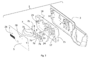
- the control panel 2 shown in FIG. 1 is displayed in FIG. 2 in an exploded view.
- the control panel 2 comprises a user interface 3 for interaction with a user.
- the user interface 3 comprises several capacitive touch input regions 4, which preferably act and/or are built as capacitive sensors, and an electronic board 5 with several conductive tracks 6. Capacitive changes occurring when the user touches a touch input region 4 are transmitted to a corresponding conductive track 6 by an electrode 7.
- the respective electrode 7 comprises an end 7a which is electrically connected to a conductive track 6 and an end 7b which is positioned at or in proximity to a capacitive touch region 4.
- the proximity to or distance between the respective end 7b and the corresponding touch region is chosen to fulfill the requirement that the capacitive change of a user touching a touch region 4 can reliably be transferred to the electronic board 5 by the respective electrode 7.
- each touch region 4 is electrically, i.e. capacitively, connected to exactly one conductive track 6 by exactly one electrode 7.
- the household appliance comprises a control panel 2 which is designed to deliver long functional reliability and strong robustness during transportation or other mechanical stress or strain, for example during the spinning phase(s) of washing program in a washing machine.
- the control panel 2 therefore comprises a capacitive module 8 which comprises an insulating support element 9 which is at least partially made of electrically insulating material.
- the electrodes 7 are partially embedded in this material and fixed, meaning each electrode 7 is not allowed to move as a whole with respect to the support element 9.
- the electrodes 7 are in their embedded state electrically insulated from each other. This insulation is achieved by the choice of the material of the insulating support element 9 in such a way that insulating material is used at least in parts of the support element 9 which are necessary for the insulation of the electrodes 7.
- the support element 9 can be completely made of electrically insulting material.
- insulting material can be used only in the regions of the support element 9 where electrodes 7 are embedded, while the peripheral parts of the support element 9 can be made of material which is not required to be electrically insulating.
- the support element 9 in the advantageous embodiment illustrated in attached Figures 2-7 comprises a single plastic body 10 made of electrically insulating material, which is obtained or created by injection molding and over-injecting on all electrodes 7, which leads to a plastic body 10 which partially embeds all electrodes 7 but leaves their ends 7a, 7b freely protruding from the plastic body 10.
- capacitive module 8 is obtained by positioning all electrodes 7 in a suitable mold, all spaced apart from the others, then injecting a melted insulating plastic material in said mold, so as to partially embed these electrodes 7 (only the ends 7a and 7b of the electrodes being not embedded by the plastic material), and then, after solidification of the plastic material, extracting the so obtained capacitive module 8 from the mold.
- the two main functions of the plastic body 10 are advantageously to fix or fixate the electrodes 7 and to electrically insulate them one another.
- the over-injection of the electrodes 7 leads to an especially stable and robust arrangement of the electrodes 7 and allows in the assembled state of the control panel 2 a reliable functioning, namely to capacitively couple a touch region 4 with the corresponding conductive track 6.
- the control panel 2 comprises a front wall 12 with an external surface 13 comprising the touch regions 4 which in a state in which the control panel 2 is positioned at or in the household appliance 1 is the surface which faces the external surrounding and provides the interface to the user.
- the control panel 2 On its opposite side, the control panel 2 comprises a rear or internal surface 14 which in an assembled state faces the electronic board 5. Both surfaces 13, 14 are advantageously surfaces of the user interface 3.
- the control panel according to FIGs. 2 and 3 further comprises a box 15 which in the assembled state houses or receives the capacitive module 8 and the electronic board 5.
- Box 15 comprises an external wall 16 which faces the internal surface 14 of the user interface 3 and an internal wall 17 facing the electronic board 5.
- the capacitive module 8 is positioned between the internal wall 17 and the electronic board 5.
- Box 15 can advantageously comprise one or more ducts 18 or openings which allow the capacitive connection between ends 7b and touch regions 4.
- Box 15 may further advantageously comprise light conductors 19 for transmitting light which is emitted from light emitting elements 20 to corresponding display elements 21 at the front wall 12 of the control panel 2.
- the attachment of the capacitive module 8 to the box 15 can be achieved in different ways.
- One possibility is a multitude of pegs 24 protruding from the internal wall 17 of box 15 which are lead through holes 21 in the plastic body 10 during assembling of the control panel 2.
- connections with clips or screws are possible.
- Box 15 is an optional component which in other advantageous embodiments can be left out.
- the capacitive module 8 can then directly be attached to the user interface 3 on its interior or internal surface 14 and/or be attached to the electronic board 5.
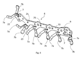
- the capacitive module 8 illustrated in FIG. 4 comprises several holes 25 through one or more of which pegs 24 protruding from the internal wall 17 of box 15 are advantageously lead.
- Plastic body 10 illustrated in FIG. 4 is advantageously shaped as rack 22 with protruding fixing pieces 23 which, by over-injection, partially embed the respective electrode 7.
- FIG. 5 displays a front view of the control panel 2 with the user interface 3 and its external surface 13.
- touch regions 4 and display elements 21 are arranged which allow the user to interact with the household appliance 1 and, for instance, to select a desired washing program.
- the feedback to the user is advantageously provided via the display elements 21.
- an LCD display or any other kind of visual indication component can be used.
- FIG. 6 shows a section through the line A-A of FIG. 5 of the control panel 2 in an assembled state.
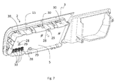
- FIG. 7 shows a back view of the control panel 2 in an assembled state.
- Box 15 has been attached to user interface 3 and capacitive module 8 has been inserted.
- the electronic board 5 has been attached to box 15.
- the connection between box 15 and electronic board 5 is preferably performed by cuts 28 in the electronic board through which snap arms 29 or engagement hooks which are connected to box 15 or are part of box 15 are put through in which way a definite and firm positioning between box 15 and electronic board 5 is achieved.
- the control panel 2 may advantageously comprise snap arms 30 which engage with projections or cuts in the housing of the household appliance 1 for a detachable connection with the household appliance 1.
- the electronic board 5 comprises several electrical connectors 33 for connecting electrical components of the household appliance.
- FIG. 8-15d A preferred variant of a method for manufacturing a capacitive module 8 is displayed in context of the following FIGs. 8-15d .
- a capacitive module 8 comprising a support element 9 with a plastic body 10 with partially embedded electrodes 7, a single metallic body 40 as displayed in FIG. 8 is used.
- the use of a single metallic body 40 simplifies the manufacturing process and the design of the cavity of the mold 50 which is employed to obtain the capacitive module 8.
- the single metallic body 40 is designed as a plurality of electrodes 7 which are connected by lateral struts 42 as to form a grid-like structure.
- the single metallic body 40 is manufactured as a one-piece component, for example by punching out from a metal plate (made of an electrical conductive metal) and bending of the conducting elements 41 in a first region 43 and a second region 44 at both of their ends, respectively.
- the single metallic body 40 is placed in a mold 50 (of which the lower component, an injection mold 55 is displayed), whereby the part of the single metallic body 40 which is later to be embedded is placed in a cavity 51 of mold 50.
- Cavity 51 is connected to a duct 53 or runner which forms a channel for directing melted insulating plastic material into cavity 51.
- Mold 50 is therefore adapted to house the single metallic body 40.
- mold 50 comprises an injection mold 55 or A-plate and an ejector mold 56 or B-plate.
- ejector mold 56 is placed on injection mold 55 and closes cavity 51 such that injected material through the runner stays in the cavity and flows around metallic body 40.
- meltted plastic material 60 is shown as it is flowing into cavity 51, flowing and partially enclosing electrode 7.
- lower projections 61 and upper projections 63 are formed which narrow the flow passage for plastic material 60, leading to the thinner parts of the resulting plastic body 10 between electrodes 7.
- the plastic body 10 thus is thicker around electrodes 7 than in between them, by which material, weight and eventually costs can be reduced.
- the electrodes 7 are reciprocally separated from each other in order to electrically insulate them from each other. This insulation is performed for example by cutting the struts 42 between neighboring electrodes 7 such that no flow of electric current between two respective electrodes 7 becomes possible.
- FIGs 12 to 15b show, in various views, the capacitive module 8 after the solidification of the plastic material composing the plastic body 10, but before the reciprocal electrical insulation of the electrodes 7 by cutting the struts 42 between neighboring electrodes 7.
- the electrical insulation is established by a cutting device, not illustrated, which is preferably integrated into the mold 50.
- the cutting device comprises a retractable cutter which can moved against an elastic element, especially a spring, to a retracting position during the inflow of melted plastic material.
- the cutter is moveable to a number of discrete positions between the housed electrodes 7 in the mold 50 and is operated to cut the struts 42 between adjacent electrodes 7 for respective electrical insulation.
- FIGs 15c and 15d show the capacitive module 8 after the reciprocal electrical insulation of the electrodes 7 by cutting the struts 42 between neighboring electrodes 7; holes 75, preferably pass-through holes, are obtained in the plastic body 10 in correspondence of the cuts of the struts 42 by the cutting device.
- plastic body 10 built from plastic material 60 is extracted from mold 50, especially from the ejector mold 56.
- capacitive module 8 resulting from the method described above, but before the cutting the struts 42 is displayed, and in FIG. 13 , capacitive module 8 of FIG. 12 is displayed from a different viewing direction.
- the part of plastic body 10 which in a direction 65 partially embeds each respective electrode 7 is designed preferably with a truncated pyramid 67.
- the capacitive module 8 of FIG. 13 is again displayed in FIG. 14 with the same viewing direction.
- plastic material 60 is represented as transparent, so that the part of the metallic body 40 which is embedded in the plastic material can be seen.
- Plastic body 10 which builds the support element 9 is manufactured by a method as described above, whereby the cavity 51 is adapted to yield a shape of plastic body 10 as shown.
- Plastic body 10 is essentially designed as a cuboid. More generally, a parallelepiped can be used as the form of the plastic body 10.
- On a top side 77, the plastic body is designed with a truncated pyramid 67 with rounded edges 79 for easier handling.
- a snap arm 85 protrudes from main body 87 of plastic body 10. In an assembled state of the control panel 2, the snap arms 85 engage with cuts, slits or openings in the box 15 or the user interface 3 in order to bring the capacitive module 8 in a fixed position with respect to the other components of the control panel 2.
- a capacitive module 8 in still another preferred embodiment is shown in FIG. 18 . It comprises a plurality (five in this example) plastic bodies 94 which are essentially shaped as cuboids and are configured respectively to build a form-fit or form-locking connection with one or two other plastic bodies 94.
- this form-fit connection is realized by respective dovetail joints 95, one of which is displayed in a magnified view within a contour 97.
- Each plastic body 94 on one side comprises a pin 99 and on the other or opposing side a tail 100. To establish the dovetail joint 95, pin 99 engages with tail 100.
- This embodiment of the capacitive module 8 is produced by injecting plastic material into a mold 50 with a cavity 51 in which one or several separate electrodes 7 are housed and which is shaped as to allow the melted plastic material to flow into the cavity to embed partially the respective electrode 7 and to form a plastic body 94.
- the cavity 51 is preferably adapted to allow toe production of several plastic bodies 94, each one partially embedding one or more electrodes 7 (one in the embodiment illustrated in FIGs.18-19 ), during one operation of injection melted plastic material 60 into the mold 50.
- the plastic bodies 94 attached to each other build the support element 9. This configuration of the capacitive module 8 allows combining plastic bodies 94 in various numbers to obtain capacitive modules 8 with a varying number of electrodes 7.
- FIG. 20 yet another preferred embodiment of a capacitive module 8 is shown which comprises several plastic bodies 94.
- Plastic bodies 94 are attached to a common rack 100.
- plastic bodies 94 are preferably not mutually connected to each other but remain in position due to being mounted on rack 100.
- additional connections between the plastic bodies 94 can also be provided to provide additional stability of the capacitive module 8.
- rack 100 On its sides 102, 104, rack 100 preferably comprises connection elements 106 designed as angled flaps or clips with a connection part 108 with a hole 110, respectively.
- Rack 100 in this way can be placed at box or user interface or electronic board and fixed, for instance, by screws which go through holes 110.
- FIG. 21 A single plastic body 94 of the capacitive module 8 according to FIG. 20 is displayed in FIG. 21 . It comprises an essentially cuboid shape. On a bottom side 112, it comprises pegs 114 which at their ends respectively comprise a fixing element 116, which are preferably made of elastic material and allow a compression in radial direction. In their usual state, they comprise a diameter larger than pegs 114.
- rack 100 is displayed in an assembled state with four plastic bodies 94. Pegs 114 have been received by holes 118 in rack 100 to establish a plug connection between respective plastic body 94 and common rack 100. As can be seen in FIG. 23 which shows an exploded view of plastic bodies 94 and rack 100, holes 118 are surrounded, respectively, by a resistance element 120. When pegs 114 are put through holes 118, fixing elements 116 are temporarily compressed and assume their original shape after the plug connection has been established, i.e., the respective plastic bodies assumes their position closest to rack 100. Fixing elements 116 then assume a diameter larger than holes 118 and the resistance elements, and essentially act as elastic engagement hooks.
- Still another possible embodiment can be constructed/designed with separate plastic bodies 94 which on one side comprise at least one peg and on the other side comprise at least one hole which can be engaged in order to provide a form-fit connection between the respective elements.
- plastic bodies 94 or bodies of non-conductive material, in which an electrode 7 is partially embedded, can be mechanically connected to each other to form a capacitive module 8.
Landscapes
- Engineering & Computer Science (AREA)
- Mechanical Engineering (AREA)
- Manufacturing & Machinery (AREA)
- Textile Engineering (AREA)
- Chemical & Material Sciences (AREA)
- Composite Materials (AREA)
- Detail Structures Of Washing Machines And Dryers (AREA)
Abstract
Description
- The invention refers to a household appliance, preferably a laundry appliance like a laundry washing machine, a laundry drier, or a washer/direr, provided with a control panel. The invention further refers to a method for manufacturing a capacitive module for a household appliance control panel system.
- Known household appliances such as laundry machines, i.e. washing machines, driers, and combined washer/driers, are usually provided with a user interface comprising a dashboard or control panel with input devices, knobs, buttons, etc., allowing the user to select or set washing and/or drying programs. The dashboards are typically provided also with output devices such as displays, LEDs, etc. for giving a feedback to the user related to the settings/status of the machine.
- Some of these dashboards are provided with capacitive touch sensitive input devices that detect the contact of the user by means of capacitive change. Known touchsensitive dashboards for instance comprise an electronic board which is connected to the mains and to the electric components of machine fixed inside a plastic box which is fixed to or obtained as a single body with the control panel.
- The electronic board is usually provided with a plurality of electric tracks constituting the electrodes of the capacitive touch sensors. A capacitive module shaped as a metallic spring is fixed to each track at one end, and at the other end it is provided with an electrode which is positioned behind a suitable printing or other indicating element in the control panel which indicates the position of the electrode. When a user positions his/her finger on the printing or indicator element, he/she changes the electric capacity detected by the electrode and therefore by the capacitive sensor.
-
WO 2011/119696 A2 discloses an appliance control panel system comprising a control panel interface with touch keys and a circuit board assembly with receiver pads. The electrical connection between the touch keys of the control panel and the corresponding receiver pads is achieved via conductive extenders which are situated between the control panel interface and the circuit board assembly. The extenders can be made of conductive material such as foam pad or can be designed as springs. - A household appliance with a control panel, a circuit board and a touch button is disclosed in
WO 2013/064572 A1 . The signal resulting from a capacitive difference when the user touches the button is transmitted to a sensor by a respective spring of which one end is fixed to the circuit board. The springs are surrounded by a housing almost without a gap. -
US 7,741,858 B2 describes a capacitive switch of an electric/electronic device with a control panel with contacts disposed at the front of the panel and capacitive sensors disposed at the rear of the control panel. A plurality of void removal elements is disposed between the capacitive sensors and the contacts and electrically connected to them. - A capacitive touch switch with a touch panel and a printed circuit board is disclosed in
EP 1 786 107 B1 - Disadvantageous of these described technical solutions is that the springs are difficult to assemble to the electronic board and to be positioned inside the box since they tend to get stuck one another. This leads to technical issues with respect to assembly. Additionally, the manufacturing of several distinct components such as separate capacitive modules or buttons is rather cost intensive.
- The aim of the invention is therefore to provide a household appliance with a very robust and reliable control panel which is easy to assemble. Another aim of the invention is to provide a method for manufacturing such a keyboard.
- The present invention therefore relates, in a first aspect thereof, to a household appliance provided with a control panel comprising: a user interface comprising one or more capacitive touch input regions; an electronic board comprising one or more electrically conductive tracks; one or more electrodes having two ends, one end being electrically connected to one of said one or more electrically conductive tracks and the other end being positioned at or in proximity of one of said one or more capacitive touch input regions. The household appliance comprises a capacitive module comprising an insulating support element, made at least partially of electrically insulating material, in which said one or more electrodes are fixed and partially embedded.
- Preferred embodiments of the invention are described in relation to the dependent claims and the description of the enclosed drawings.
- The invention is based on the consideration that the control panel of the household appliance is an essential component of which robust and reliable functionality are demanded. Since household appliances are usually and often transported to the customer the corresponding components should provide mechanical robustness and should allow being subjected to mechanical stress without losing their functionality. Especially important for operating a household appliance is the functionality that user commands are accurately transferred to the control logic which, dependent on the user choice, controls the appliance. With known solutions, already during the assembly of the appliance problems may arise with false positioning of the electrodes. During transport, components may move and wedge which in the long term may lead to reduced functionality or failure.
- The applicant has found that these problems can be avoided if the one or more electrodes are firmly embedded in a body made of at least partially non-conductive (preferably plastic) material surrounding them. This leads to a well-defined spatial orientation and reciprocal positioning of the electrodes when the capacitive module is installed. During transport, no friction or contact between lose component is thus allowed. Thus, in the long term, reliable functionality of the control panel can be provided.
- The term "embedded" hereby means that the respective electrode is partially surrounded or enclosed by the material in such a way that it cannot be removed without breaking or tearing apart the non-conductive or plastic material.
- In a preferred embodiment at least two electrodes are fixed and partially embedded in the at least partially electrically insulating material in such a way to be reciprocally electrically insulated one another. Preferably, the number of touch regions and the number of conductive tracks respectively correspond to the number of electrodes, whereby each electrode advantageously connects exactly one touch region with one conductive track. The connection hereby involves the functionality that a capacitive change of the touch input region, which preferably is built as a capacitive sensor, is signaled and/or transported to the electronic board, allowing it to react. The electrodes that connect directly neighboring touch regions are advantageously positioned next to each other in order to avoid unnecessary distances and/or contacts which could lead to malfunctions.
- Preferably, the insulating support element comprises a single plastic body obtained by injection molding and over-injected on all said one or more electrodes in such a way to partially embed all of them and to allow said two ends of each electrode to protrude externally from said plastic body. Such a configuration is especially robust and easy to handle in the assembling process of the control panel.
- The term "over-injection" denotes the process of injection molding, where material is injected into a mold in which the at least one electrode is placed in such a way that the material moves around the electrode and encloses it partially and partially covers it. The respective electrode is thus partly both embedded and fixed in the material.
- In an alternative embodiment, the insulating support element comprises a plurality of plastic bodies obtained by injection molding and each one over-injected on at least one of said one or more electrodes in such a way to partially embed it and to allow said two ends of said at least one of said one or more electrodes to protrude externally from said plastic body.
- In an advantageous embodiment, the plastic bodies, each comprising at least one of said one or more electrodes, are advantageously connected one another after their injection molding so as to form said capacitive module. For the connection between two plastic bodies, any kind of suitable mechanical connection can be used as long as it allows a well-defined and firm relative positioning between two adjacent plastic bodies.
- In an advantageous embodiment, in order to provide a robust connection between the plastic bodies, the plurality of plastic bodies is preferably fixed to a rack supporting them. Additionally, the plastic bodies can be advantageously connected one another to provide extra stability.
- The control panel of the household appliance advantageously comprises a front wall having an external surface facing the external of the appliance and comprising one or more capacitive touch input regions, the control panel comprising an internal surface provided in or in proximity of the front wall and facing the electronic board, the capacitive module being positioned between electronic board and internal or rear surface.
- Preferably, the control panel comprises a box housing the electronic board and having an external wall facing the front wall of the control panel, the external wall comprising the internal surface facing the electronic board and the capacitive module being positioned between the electronic board and internal surface. A box can provide extra stability and provide protection of the electronic components with respect to environmental influences.
- Advantageously, the end of an electrode positioned at or in proximity of one of the one or more capacitive touch input regions abuts against the internal surface of the control panel and is made of an elastic conductive material so as to elastically adapt its shape/position to the actual distance between the respective conductive track and the internal surface of the control panel. Such a configuration allows establishing reliable electrical contact for an interval of distances between the respective conductive track and the internal surface of the control panel and thus can compensate for tolerances during the manufacturing and/or assembling processes.
- Preferably the household appliance is a laundry washing machine or a laundry drier or a washer-drier. It has to be understood that the invention is particularly useful for laundry washing machines and washer-driers, since in use they are exposed to high vibrations (in particular during the spinning phases), and therefore the robustness of the capacitive module is essential.
- The present invention relates, in a second aspect thereof, to a method for manufacturing a capacitive module for a household appliance control panel, comprising the steps
- a) providing a mold adapted to house one or more electrodes, said mold being arranged in such a way that by injecting a melted insulating plastic material in said mold after housing said one or more electrodes therein, the one or more electrodes are partially embedded in a plastic body formed by the plastic material and protrude with two ends from the plastic body;
- b) housing one or more electrodes in the mold;
- c) injecting a melted insulating plastic material in the mold so as to obtain a capacitive module comprising one or more electrodes and a plastic body partially embedding said one or more electrodes;
- d) extracting the capacitive module from the mold.
- In a preferred variant or embodiment, the mold is adapted to house a plurality of electrodes, one spaced apart from the others/mutually spaced apart from each other, the above described phase or step b) comprising housing a plurality of electrodes, one spaced apart from the others or mutually spaced apart from each other, in the mold.
- In another preferred variant, the mold is adapted to house a single metallic body comprising a plurality of electrodes, phase or step b) comprising housing the single metallic body in the mold, wherein this method comprises, after phase or step c), the following step:
- c1) reciprocally separating the electrodes of the metallic body so as to electrically insulate them one another, while keeping them partially embedded in the plastic body.
- A single metallic body is easy to produce by die cutting of a metal plate and provides well-defined distances between the electrodes during the process of injection molding.
- Preferably, step c1) is performed before performing phase or step d); i.e. step c1) is performed while the capacitive module is still in the mold, for example by using a cutting element provided in the mold and adapted to reciprocally separate the electrodes while they are housed in the mold.
- In a preferred variant, a capacitive module with a plurality of plastic bodies is produced, each one embedding one or more electrodes, further comprising the step of connecting the plurality of plastic bodies one to the other via respective plastic bodies.
- The advantages of the invention are especially as follows. The capacitive module provides an integration of components and consequently leads to a reduction of parts. This allows cost saving since the production of a single module is less expensive than the production of several loose components. When several plastic bodies are produced which are then connected to each other or to a common support structure, variants with different number of electrodes can easily be assembled.
- The capacitive module allows a comfortable handling in all production phases and an easy and reliable assembling operation. Moreover, damages during transport can be reduced and safety can be increased, which enhance the reliability and life period of the control panel and the household appliance.
- Further characteristics and advantages of the present invention will be highlighted in greater detail in the following detailed description of some of its preferred embodiments, provided with reference to the enclosed drawings. In said drawings:
- FIG. 1
- shows a household appliance with a control panel;
- FIG. 2
- shows the control panel shown in
FIG. 1 comprising a user interface, an electronic board, a box and a capacitive module in a first preferred embodiment with six electrodes in an exploded view from a first viewing angle; - FIG. 3
- shows the control panel of
FIGs. 1 and2 in an exploded view from a second viewing angle; - FIG. 4
- shows a capacitive module of the control panel shown in
FIGs. 1 through 3 with six embedded electrodes; - FIG. 5
- shows the control panel of
FIGs. 1 through 3 in a front view; - FIG. 6
- shows the control panel of
FIG. 5 in a side view; - FIG. 7
- shows the control panel of
FIG. 5 in a back view; - FIG. 8
- shows a single metallic body used in a preferred variant of a method for manufacturing a control panel;
- FIG. 9
- shows a mold used in the preferred method variant with the single metallic body of
FIG. 8 placed in a cavity; - FIG. 10
- shows the mold according to
FIG. 9 with an upper component; - FIG. 11
- shows a detailed view of a part of the cavity with inflowing plastic material;
- FIG. 12
- shows a capacitive module in a second preferred embodiment manufactured by the method illustrated in
FIGs. 8 through 11 with a support element and four embedded electrodes; - FIG. 13
- shows the capacitive module of
FIG. 12 in a perspective view; - FIG. 14
- shows the capacitive module of
FIGs. 12 and 13 whereby the support element is drawn as a transparent lattice model; - FIG. 15a
- shows the capacitive module of
FIGs. 12 to 14 form a top view before the cutting of the struts between neighboring electrodes; - FIG. 15b
- shows the capacitive module of
FIG 15a in a schematic view in which the insulating support member is represented as transparent, so as to allow seeing the embedded part of the electrodes; - FIG. 15c
- shows the capacitive module of
FIGs. 12 to 14 form a top view after the cutting of the struts between neighboring electrodes; - FIG. 15d
- shows the capacitive module of
FIG 15c in a schematic view in which the insulating support member is represented as transparent, so as to allow seeing the embedded part of the electrodes; - FIG. 16
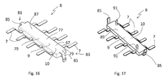
- shows a third preferred embodiment of a capacitive module in a perspective view;
- FIG. 17
- shows the capacitive module of
FIG. 16 from a different perspective; - FIG. 18
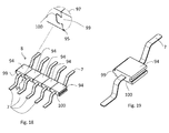
- shows a capacitive module with a plurality of plastic bodies in a fourth preferred embodiment in a perspective view;
- FIG. 19
- shows a plastic body of the capacitive module of
FIG. 18 ; - FIG. 20
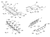
- shows a capacitive module with a plurality of plastic bodies in a fifth preferred embodiment attached to a rack in a perspective view;
- FIG. 21
- shows a plastic body of the capacitive module of
FIG. 20 ; - FIG. 22
- shows the capacitive module of
FIG. 20 in a different view; - FIG. 23
- shows the capacitive module of
FIG. 20 in an exploded view. - With reference to
FIG. 1 , ahousehold appliance 1 is shown which is built as a front-loading laundry washing machine. Anyway the invention can be applied as well to top-loading washing machines, to laundry washer/driers and to tumble driers.Washing machine 1 advantageously comprises acontrol panel 2 through which the user can interact with the washing machine by, for instance, selecting a certain laundry program. - The
control panel 2 shown inFIG. 1 is displayed inFIG. 2 in an exploded view. Thecontrol panel 2 comprises auser interface 3 for interaction with a user. Theuser interface 3 comprises several capacitivetouch input regions 4, which preferably act and/or are built as capacitive sensors, and anelectronic board 5 with severalconductive tracks 6. Capacitive changes occurring when the user touches atouch input region 4 are transmitted to a correspondingconductive track 6 by anelectrode 7. Therespective electrode 7 comprises anend 7a which is electrically connected to aconductive track 6 and anend 7b which is positioned at or in proximity to acapacitive touch region 4. The proximity to or distance between therespective end 7b and the corresponding touch region is chosen to fulfill the requirement that the capacitive change of a user touching atouch region 4 can reliably be transferred to theelectronic board 5 by therespective electrode 7. - Advantageously, the configuration of
touch regions 4,electrodes 7, andelectronic board 5 is chosen in such a way that eachtouch region 4 is electrically, i.e. capacitively, connected to exactly oneconductive track 6 by exactly oneelectrode 7. - The household appliance comprises a
control panel 2 which is designed to deliver long functional reliability and strong robustness during transportation or other mechanical stress or strain, for example during the spinning phase(s) of washing program in a washing machine. Thecontrol panel 2 therefore comprises acapacitive module 8 which comprises an insulatingsupport element 9 which is at least partially made of electrically insulating material. Theelectrodes 7 are partially embedded in this material and fixed, meaning eachelectrode 7 is not allowed to move as a whole with respect to thesupport element 9. Theelectrodes 7 are in their embedded state electrically insulated from each other. This insulation is achieved by the choice of the material of the insulatingsupport element 9 in such a way that insulating material is used at least in parts of thesupport element 9 which are necessary for the insulation of theelectrodes 7. Thesupport element 9 can be completely made of electrically insulting material. Alternatively, in one advantageous embodiment, insulting material can be used only in the regions of thesupport element 9 whereelectrodes 7 are embedded, while the peripheral parts of thesupport element 9 can be made of material which is not required to be electrically insulating. - The
support element 9 in the advantageous embodiment illustrated in attachedFigures 2-7 , comprises a singleplastic body 10 made of electrically insulating material, which is obtained or created by injection molding and over-injecting on allelectrodes 7, which leads to aplastic body 10 which partially embeds allelectrodes 7 but leaves theirends plastic body 10. - In this advantageous embodiment,
capacitive module 8 is obtained by positioning allelectrodes 7 in a suitable mold, all spaced apart from the others, then injecting a melted insulating plastic material in said mold, so as to partially embed these electrodes 7 (only theends capacitive module 8 from the mold. - The two main functions of the
plastic body 10 are advantageously to fix or fixate theelectrodes 7 and to electrically insulate them one another. The over-injection of theelectrodes 7 leads to an especially stable and robust arrangement of theelectrodes 7 and allows in the assembled state of the control panel 2 a reliable functioning, namely to capacitively couple atouch region 4 with the correspondingconductive track 6. - The
control panel 2 comprises a front wall 12 with anexternal surface 13 comprising thetouch regions 4 which in a state in which thecontrol panel 2 is positioned at or in thehousehold appliance 1 is the surface which faces the external surrounding and provides the interface to the user. On its opposite side, thecontrol panel 2 comprises a rear orinternal surface 14 which in an assembled state faces theelectronic board 5. Both surfaces 13, 14 are advantageously surfaces of theuser interface 3. - The control panel according to
FIGs. 2 and3 further comprises abox 15 which in the assembled state houses or receives thecapacitive module 8 and theelectronic board 5.Box 15 comprises anexternal wall 16 which faces theinternal surface 14 of theuser interface 3 and aninternal wall 17 facing theelectronic board 5. In an assembled state, thecapacitive module 8 is positioned between theinternal wall 17 and theelectronic board 5.Box 15 can advantageously comprise one ormore ducts 18 or openings which allow the capacitive connection between ends 7b andtouch regions 4.Box 15 may further advantageously comprise light conductors 19 for transmitting light which is emitted from light emittingelements 20 to correspondingdisplay elements 21 at the front wall 12 of thecontrol panel 2. - The attachment of the
capacitive module 8 to thebox 15 can be achieved in different ways. One possibility is a multitude ofpegs 24 protruding from theinternal wall 17 ofbox 15 which are lead throughholes 21 in theplastic body 10 during assembling of thecontrol panel 2. Also, connections with clips or screws are possible. -
Box 15 is an optional component which in other advantageous embodiments can be left out. Thecapacitive module 8 can then directly be attached to theuser interface 3 on its interior orinternal surface 14 and/or be attached to theelectronic board 5. - The
capacitive module 8 illustrated inFIG. 4 comprisesseveral holes 25 through one or more of which pegs 24 protruding from theinternal wall 17 ofbox 15 are advantageously lead.Plastic body 10 illustrated inFIG. 4 is advantageously shaped asrack 22 with protruding fixingpieces 23 which, by over-injection, partially embed therespective electrode 7. -
FIG. 5 displays a front view of thecontrol panel 2 with theuser interface 3 and itsexternal surface 13. On itssurface 13,touch regions 4 and displayelements 21 are arranged which allow the user to interact with thehousehold appliance 1 and, for instance, to select a desired washing program. The feedback to the user is advantageously provided via thedisplay elements 21. Alternatively, an LCD display or any other kind of visual indication component can be used. -
FIG. 6 shows a section through the line A-A ofFIG. 5 of thecontrol panel 2 in an assembled state. -
FIG. 7 shows a back view of thecontrol panel 2 in an assembled state.Box 15 has been attached touser interface 3 andcapacitive module 8 has been inserted. Theelectronic board 5 has been attached tobox 15. The connection betweenbox 15 andelectronic board 5 is preferably performed bycuts 28 in the electronic board through which snaparms 29 or engagement hooks which are connected to box 15 or are part ofbox 15 are put through in which way a definite and firm positioning betweenbox 15 andelectronic board 5 is achieved. Thecontrol panel 2 may advantageously comprisesnap arms 30 which engage with projections or cuts in the housing of thehousehold appliance 1 for a detachable connection with thehousehold appliance 1. - The
electronic board 5 comprises severalelectrical connectors 33 for connecting electrical components of the household appliance. - A preferred variant of a method for manufacturing a
capacitive module 8 is displayed in context of the followingFIGs. 8-15d . In order to obtain acapacitive module 8 comprising asupport element 9 with aplastic body 10 with partially embeddedelectrodes 7, a singlemetallic body 40 as displayed inFIG. 8 is used. - The use of a single
metallic body 40 simplifies the manufacturing process and the design of the cavity of themold 50 which is employed to obtain thecapacitive module 8. The singlemetallic body 40 is designed as a plurality ofelectrodes 7 which are connected bylateral struts 42 as to form a grid-like structure. The singlemetallic body 40 is manufactured as a one-piece component, for example by punching out from a metal plate (made of an electrical conductive metal) and bending of the conducting elements 41 in afirst region 43 and asecond region 44 at both of their ends, respectively. - As illustrated in
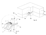
FIG. 9 , the singlemetallic body 40 is placed in a mold 50 (of which the lower component, aninjection mold 55 is displayed), whereby the part of the singlemetallic body 40 which is later to be embedded is placed in acavity 51 ofmold 50.Cavity 51 is connected to aduct 53 or runner which forms a channel for directing melted insulating plastic material intocavity 51.Mold 50 is therefore adapted to house the singlemetallic body 40. - With reference to
FIG. 10 , which shows a section through themold 50 andcavity 51,mold 50 comprises aninjection mold 55 or A-plate and anejector mold 56 or B-plate. During the injection molding process,ejector mold 56 is placed oninjection mold 55 and closescavity 51 such that injected material through the runner stays in the cavity and flows aroundmetallic body 40. - With reference now to
FIG. 11 , in a circle 58 a magnified view ofmold 50 is shown. Meltedplastic material 60 is shown as it is flowing intocavity 51, flowing and partially enclosingelectrode 7. On opposite sides incavity 51,lower projections 61 andupper projections 63 are formed which narrow the flow passage forplastic material 60, leading to the thinner parts of the resultingplastic body 10 betweenelectrodes 7. Theplastic body 10 thus is thicker aroundelectrodes 7 than in between them, by which material, weight and eventually costs can be reduced. - After the phase of injecting the
plastic material 60 into thecavity 51 and afterplastic material 60 has partially embedded the singlemetallic body 40, theelectrodes 7 are reciprocally separated from each other in order to electrically insulate them from each other. This insulation is performed for example by cutting thestruts 42 between neighboringelectrodes 7 such that no flow of electric current between tworespective electrodes 7 becomes possible. -
FIGs 12 to 15b show, in various views, thecapacitive module 8 after the solidification of the plastic material composing theplastic body 10, but before the reciprocal electrical insulation of theelectrodes 7 by cutting thestruts 42 between neighboringelectrodes 7. - The electrical insulation is established by a cutting device, not illustrated, which is preferably integrated into the
mold 50. Preferably, the cutting device comprises a retractable cutter which can moved against an elastic element, especially a spring, to a retracting position during the inflow of melted plastic material. The cutter is moveable to a number of discrete positions between the housedelectrodes 7 in themold 50 and is operated to cut thestruts 42 betweenadjacent electrodes 7 for respective electrical insulation. -
FIGs 15c and 15d show thecapacitive module 8 after the reciprocal electrical insulation of theelectrodes 7 by cutting thestruts 42 between neighboringelectrodes 7;holes 75, preferably pass-through holes, are obtained in theplastic body 10 in correspondence of the cuts of thestruts 42 by the cutting device. - After plastic material has sufficiently hardened, and after cutting of the
struts 42,plastic body 10 built fromplastic material 60 is extracted frommold 50, especially from theejector mold 56. - In
FIG. 12 , acapacitive module 8 resulting from the method described above, but before the cutting thestruts 42 is displayed, and inFIG. 13 ,capacitive module 8 ofFIG. 12 is displayed from a different viewing direction. The part ofplastic body 10 which in adirection 65 partially embeds eachrespective electrode 7 is designed preferably with atruncated pyramid 67. - The
capacitive module 8 ofFIG. 13 is again displayed inFIG. 14 with the same viewing direction. For viewing purposes,plastic material 60 is represented as transparent, so that the part of themetallic body 40 which is embedded in the plastic material can be seen. - A
capacitive module 8 in another preferred embodiment is displayed inFIG. 16 .Plastic body 10 which builds thesupport element 9 is manufactured by a method as described above, whereby thecavity 51 is adapted to yield a shape ofplastic body 10 as shown.Plastic body 10 is essentially designed as a cuboid. More generally, a parallelepiped can be used as the form of theplastic body 10. On atop side 77, the plastic body is designed with atruncated pyramid 67 with roundededges 79 for easier handling. On eachside plastic body 10, asnap arm 85 protrudes frommain body 87 ofplastic body 10. In an assembled state of thecontrol panel 2, thesnap arms 85 engage with cuts, slits or openings in thebox 15 or theuser interface 3 in order to bring thecapacitive module 8 in a fixed position with respect to the other components of thecontrol panel 2. - With reference now to
FIG. 17 , from abottom side 89 ofcapacitive module 8 according toFIG. 16 , two pins or pegs 91 protrude vertically which engage in holes onbox 15 oruser interface 3. - A
capacitive module 8 in still another preferred embodiment is shown inFIG. 18 . It comprises a plurality (five in this example)plastic bodies 94 which are essentially shaped as cuboids and are configured respectively to build a form-fit or form-locking connection with one or two otherplastic bodies 94. In the present embodiment, this form-fit connection is realized by respective dovetail joints 95, one of which is displayed in a magnified view within acontour 97. Eachplastic body 94 on one side comprises apin 99 and on the other or opposing side atail 100. To establish the dovetail joint 95,pin 99 engages withtail 100. - This embodiment of the
capacitive module 8 is produced by injecting plastic material into amold 50 with acavity 51 in which one or severalseparate electrodes 7 are housed and which is shaped as to allow the melted plastic material to flow into the cavity to embed partially therespective electrode 7 and to form aplastic body 94. Thecavity 51 is preferably adapted to allow toe production of severalplastic bodies 94, each one partially embedding one or more electrodes 7 (one in the embodiment illustrated inFIGs.18-19 ), during one operation of injection meltedplastic material 60 into themold 50. Theplastic bodies 94 attached to each other build thesupport element 9. This configuration of thecapacitive module 8 allows combiningplastic bodies 94 in various numbers to obtaincapacitive modules 8 with a varying number ofelectrodes 7. - In
FIG. 20 , yet another preferred embodiment of acapacitive module 8 is shown which comprises severalplastic bodies 94.Plastic bodies 94 are attached to acommon rack 100. Hence, in contrast to the embodiment ofFIGs. 18 and 19 ,plastic bodies 94 are preferably not mutually connected to each other but remain in position due to being mounted onrack 100. In other possible embodiments, additional connections between theplastic bodies 94 can also be provided to provide additional stability of thecapacitive module 8. - On its
sides rack 100 preferably comprisesconnection elements 106 designed as angled flaps or clips with aconnection part 108 with ahole 110, respectively.Rack 100 in this way can be placed at box or user interface or electronic board and fixed, for instance, by screws which go throughholes 110. - A single
plastic body 94 of thecapacitive module 8 according toFIG. 20 is displayed inFIG. 21 . It comprises an essentially cuboid shape. On abottom side 112, it comprisespegs 114 which at their ends respectively comprise a fixingelement 116, which are preferably made of elastic material and allow a compression in radial direction. In their usual state, they comprise a diameter larger thanpegs 114. - In
FIG. 22 ,rack 100 is displayed in an assembled state with fourplastic bodies 94.Pegs 114 have been received byholes 118 inrack 100 to establish a plug connection between respectiveplastic body 94 andcommon rack 100. As can be seen inFIG. 23 which shows an exploded view ofplastic bodies 94 andrack 100,holes 118 are surrounded, respectively, by aresistance element 120. When pegs 114 are put throughholes 118, fixingelements 116 are temporarily compressed and assume their original shape after the plug connection has been established, i.e., the respective plastic bodies assumes their position closest to rack 100. Fixingelements 116 then assume a diameter larger thanholes 118 and the resistance elements, and essentially act as elastic engagement hooks. - Still another possible embodiment can be constructed/designed with separate
plastic bodies 94 which on one side comprise at least one peg and on the other side comprise at least one hole which can be engaged in order to provide a form-fit connection between the respective elements. Preferably, two pegs and two holes are used. The invention comprises all possible embodiments in whichplastic bodies 94 or bodies of non-conductive material, in which anelectrode 7 is partially embedded, can be mechanically connected to each other to form acapacitive module 8.
Claims (15)
- Household appliance (1) provided with a control panel (2) comprising:- a user interface (3) comprising one or more capacitive touch input regions (4);- an electronic board (5) comprising one or more electrically conductive tracks (6);- one or more electrodes (7) having two ends (7a, 7b), one end (7a) being electrically connected to one of said one or more electrically conductive tracks (6) and the other end (7b) being positioned at or in proximity of one of said one or more capacitive touch input regions (4),said household appliance (1) being characterized by comprising a capacitive module (8) comprising an insulating support element (9), made at least partially of electrically insulating material, in which said one or more electrodes (7) are fixed and partially embedded.
- Household appliance (1) according to claim 1 comprising at least two electrodes (7) fixed and partially embedded in said insulating support element (9) in such a way to be reciprocally electrically insulated one another.
- Household appliance (1) according to claim 1 or 2, wherein said insulating support element (9) comprises a single plastic body (10) obtained by injection molding and over-injected on all said one or more electrodes (7) in such a way to partially embed all of them and to allow said two ends (7a, 7b) of each electrode (7) to protrude externally from said plastic body (10).
- Household appliance (1) according to claim 1 or 2, wherein said insulating support element (9) comprises a plurality of plastic bodies (94) obtained by injection molding and each one over-injected on at least one of said one or more electrodes (7) in such a way to partially embed it and to allow said two ends (7a, 7b) of said at least one of said one or more electrodes (7) to protrude externally from said plastic body (94).
- Household appliance (1) according to claim 4, wherein said plurality of plastic bodies (94), each comprising at least one of said one or more electrodes (7), are connected one another after their injection molding so as to form said capacitive module (8).
- Household appliance (1) according to claim 4 or 5, wherein said plurality of plastic bodies (94), each comprising at least one of said one or more electrodes (7), are fixed to a rack (100) supporting them.
- Household appliance (1) according to one or more of the previous claims, wherein said control panel (2) comprises a front wall (12) having an external surface (13) facing the external of the appliance (1) and comprising said one or more capacitive touch input regions (4), said control panel (2) comprising an internal surface (14) provided in or in proximity of said front wall (12) and facing said electronic board (5), said capacitive module (8) being positioned between said electronic board (5) and said internal surface (14).
- Household appliance (1) according to claim 7, wherein said control panel comprises a box (15) housing said electronic board (5) and having an external wall (16) facing said front wall (12) of said control panel (2), said external wall (16) comprising said internal surface (14) facing said electronic board (5)
- Household appliance (1) according to one or more of the previous claims, wherein said end (7b) of said one or more electrodes (7) positioned at or in proximity of one of said one or more capacitive touch input regions (4) abuts against said internal surface (14) of said control panel (2), and is made of an elastic conductive material so as to elastically adapt its shape/position to the actual distance between the respective conductive track (6) and said internal surface (14) of said control panel (2).
- Household appliance (1) according to one or more of the previous claims wherein said household appliance (1) is a laundry washing machine or a laundry drier or a washer-drier.
- Method for manufacturing a capacitive module (8) for a household appliance (1) control panel (2), comprising the following steps:a) providing a mold (50) adapted to house one or more electrodes (7), said mold (50) being arranged in such a way that by injecting a melted insulating plastic material in said mold (50) after housing said one or more electrodes (7) therein, said one or more electrodes (7) are partially embedded in a plastic body (10, 94) formed by said plastic material and protrude with two ends (7a, 7b) from said plastic body (10, 94);b) housing one or more electrodes (7) in said mold (50);c) injecting a melted insulating plastic material in said mold (50), so as to obtain a capacitive module (8) comprising said one or more electrodes (7) and a plastic body (10, 94) partially embedding said one or more electrodes (7);d) extracting said capacitive module (8) from said mold (50).
- Method according to claim 11, wherein said mold (50) is adapted to house a plurality of electrodes (7), one spaced apart from the others, said step b) comprising housing a plurality of electrodes (7), one spaced apart from the others, in said mold (50).
- Method according to claim 11, wherein said mold is adapted to house a single metallic body (40) comprising a plurality of electrodes (7), said step b) comprising housing said single metallic body (40) in said mold (50), wherein said method comprises, after said step c), the following step:c1) reciprocally separating said electrodes (7) of said metallic body (40) so as to electrically insulate them one another, while keeping them partially embedded in said plastic body (10).
- Method according to claim 13, wherein said step c1) is performed before performing said phase d).
- Method, according to claim 11 or 12, comprising producing a capacitive module (8) with a plurality of plastic bodies (94), each one embedding one or more electrodes (7), said method further comprising the step of connecting said plurality of plastic bodies (94) one to the other via respective plastic bodies (94).
Priority Applications (2)
| Application Number | Priority Date | Filing Date | Title |
|---|---|---|---|
| EP13193914.2A EP2876196A1 (en) | 2013-11-21 | 2013-11-21 | Household appliance provided with a control panel |
| PCT/EP2014/073435 WO2015074851A1 (en) | 2013-11-21 | 2014-10-31 | Household appliance provided with a control panel |
Applications Claiming Priority (1)
| Application Number | Priority Date | Filing Date | Title |
|---|---|---|---|
| EP13193914.2A EP2876196A1 (en) | 2013-11-21 | 2013-11-21 | Household appliance provided with a control panel |
Publications (1)
| Publication Number | Publication Date |
|---|---|
| EP2876196A1 true EP2876196A1 (en) | 2015-05-27 |
Family
ID=49666997
Family Applications (1)
| Application Number | Title | Priority Date | Filing Date |
|---|---|---|---|
| EP13193914.2A Withdrawn EP2876196A1 (en) | 2013-11-21 | 2013-11-21 | Household appliance provided with a control panel |
Country Status (2)
| Country | Link |
|---|---|
| EP (1) | EP2876196A1 (en) |
| WO (1) | WO2015074851A1 (en) |
Cited By (4)
| Publication number | Priority date | Publication date | Assignee | Title |
|---|---|---|---|---|
| EP3187647A1 (en) | 2015-12-29 | 2017-07-05 | Electrolux Appliances Aktiebolag | Household appliance with an electronic board and method for manufacturing a household appliance |
| EP3187648A1 (en) * | 2015-12-29 | 2017-07-05 | Electrolux Appliances Aktiebolag | Household appliance |
| CN107408943A (en) * | 2015-10-30 | 2017-11-28 | Ls汽车电子株式会社 | Soft-touch control unit and the internal lighting device for vehicle including the soft-touch control unit |
| DE102017200595A1 (en) * | 2016-11-15 | 2018-05-17 | Volkswagen Aktiengesellschaft | Device with touch-sensitive freeform surface and method for its production |
Families Citing this family (2)
| Publication number | Priority date | Publication date | Assignee | Title |
|---|---|---|---|---|
| JP2021146107A (en) * | 2020-03-23 | 2021-09-27 | 東芝ライフスタイル株式会社 | Operation panel and washing machine |
| EP4001767A1 (en) * | 2020-11-19 | 2022-05-25 | Electrolux Appliances Aktiebolag | User interaction device, household appliance and method for manufacturing a user interaction device |
Citations (11)
| Publication number | Priority date | Publication date | Assignee | Title |
|---|---|---|---|---|
| DE4407508A1 (en) * | 1994-03-07 | 1995-09-14 | Duerrwaechter E Dr Doduco | Embedding electrical conductors in plastic |
| DE10305364A1 (en) * | 2002-03-28 | 2003-10-16 | Siemens Ag | Packaging e.g. vehicle braking sensor electronics, hot-sprays insulant onto lead frame where its energies are dissipated, before coating electronics |
| EP1357774A1 (en) * | 2002-04-26 | 2003-10-29 | Pollmann Austria OHG | Method for fabricating a plastic coated conductive structure of an electrical circuit unit as well as an electrical circuit unit comprising a plastic coated conductive structure |
| EP1672797A2 (en) * | 2004-12-17 | 2006-06-21 | Diehl AKO Stiftung & Co. KG | Capacitive touch switch |
| DE102005039086A1 (en) * | 2005-08-04 | 2007-02-08 | Prettl, Rolf | Electrical interconnector for equipment is produced as metal pressing conductor moulded into a plastic body |
| EP2053745A1 (en) * | 2007-10-24 | 2009-04-29 | Diehl AKO Stiftung & Co. KG | Capacitive contact switch |
| EP1786107B1 (en) | 2005-11-09 | 2010-03-03 | Diehl AKO Stiftung & Co. KG | Capacitive touch-sensitive switch |
| US7741858B2 (en) | 2006-06-09 | 2010-06-22 | Lg Electronics Inc. | Capacitive switch of electric/electronic device |
| WO2011119696A2 (en) | 2010-03-24 | 2011-09-29 | Whirlpool Corporation | Touch screen coupling having tactile response capability |
| EP2541771A1 (en) * | 2011-07-01 | 2013-01-02 | Electrolux Home Products Corporation N.V. | Method of manufacturing an electrical switching element |
| WO2013064572A1 (en) | 2011-11-04 | 2013-05-10 | Arcelik Anonim Sirketi | A household appliance comprising a touch button |
-
2013
- 2013-11-21 EP EP13193914.2A patent/EP2876196A1/en not_active Withdrawn
-
2014
- 2014-10-31 WO PCT/EP2014/073435 patent/WO2015074851A1/en active Application Filing
Patent Citations (11)
| Publication number | Priority date | Publication date | Assignee | Title |
|---|---|---|---|---|
| DE4407508A1 (en) * | 1994-03-07 | 1995-09-14 | Duerrwaechter E Dr Doduco | Embedding electrical conductors in plastic |
| DE10305364A1 (en) * | 2002-03-28 | 2003-10-16 | Siemens Ag | Packaging e.g. vehicle braking sensor electronics, hot-sprays insulant onto lead frame where its energies are dissipated, before coating electronics |
| EP1357774A1 (en) * | 2002-04-26 | 2003-10-29 | Pollmann Austria OHG | Method for fabricating a plastic coated conductive structure of an electrical circuit unit as well as an electrical circuit unit comprising a plastic coated conductive structure |
| EP1672797A2 (en) * | 2004-12-17 | 2006-06-21 | Diehl AKO Stiftung & Co. KG | Capacitive touch switch |
| DE102005039086A1 (en) * | 2005-08-04 | 2007-02-08 | Prettl, Rolf | Electrical interconnector for equipment is produced as metal pressing conductor moulded into a plastic body |
| EP1786107B1 (en) | 2005-11-09 | 2010-03-03 | Diehl AKO Stiftung & Co. KG | Capacitive touch-sensitive switch |
| US7741858B2 (en) | 2006-06-09 | 2010-06-22 | Lg Electronics Inc. | Capacitive switch of electric/electronic device |
| EP2053745A1 (en) * | 2007-10-24 | 2009-04-29 | Diehl AKO Stiftung & Co. KG | Capacitive contact switch |
| WO2011119696A2 (en) | 2010-03-24 | 2011-09-29 | Whirlpool Corporation | Touch screen coupling having tactile response capability |
| EP2541771A1 (en) * | 2011-07-01 | 2013-01-02 | Electrolux Home Products Corporation N.V. | Method of manufacturing an electrical switching element |
| WO2013064572A1 (en) | 2011-11-04 | 2013-05-10 | Arcelik Anonim Sirketi | A household appliance comprising a touch button |
Cited By (12)
| Publication number | Priority date | Publication date | Assignee | Title |
|---|---|---|---|---|
| CN107408943A (en) * | 2015-10-30 | 2017-11-28 | Ls汽车电子株式会社 | Soft-touch control unit and the internal lighting device for vehicle including the soft-touch control unit |
| EP3297164A4 (en) * | 2015-10-30 | 2018-08-08 | LS Automotive Technologies Co., Ltd. | Touch switch unit and indoor lighting device for vehicle including same |
| JP2018529178A (en) * | 2015-10-30 | 2018-10-04 | エルエス オートモーティブ テクノロジーズ カンパニー リミテッドLs Automotive Technologies Co., Ltd. | Touch switch unit and vehicle interior lighting device including the same |
| US10355689B2 (en) | 2015-10-30 | 2019-07-16 | Ls Automotive Technologies Co., Ltd. | Touch switch unit and interior lighting apparatus for vehicle including the same |
| CN107408943B (en) * | 2015-10-30 | 2021-12-28 | 乐星汽车科技有限公司 | Touch switch unit and interior lighting device for vehicle including the same |
| EP3187647A1 (en) | 2015-12-29 | 2017-07-05 | Electrolux Appliances Aktiebolag | Household appliance with an electronic board and method for manufacturing a household appliance |
| EP3187648A1 (en) * | 2015-12-29 | 2017-07-05 | Electrolux Appliances Aktiebolag | Household appliance |
| WO2017114642A1 (en) | 2015-12-29 | 2017-07-06 | Electrolux Appliances Aktiebolag | Household appliance with an electronic board and method for manufacturing a household appliance |
| US9988755B2 (en) | 2015-12-29 | 2018-06-05 | Electrolux Appliances Aktiebolag | Household appliance |
| US10954619B2 (en) | 2015-12-29 | 2021-03-23 | Electrolux Appliances Aktiebolag | Household appliance with an electronic board and method for manufacturing a household appliance |
| DE102017200595A1 (en) * | 2016-11-15 | 2018-05-17 | Volkswagen Aktiengesellschaft | Device with touch-sensitive freeform surface and method for its production |
| US10938391B2 (en) | 2016-11-15 | 2021-03-02 | Volkswagen Aktiengesellschaft | Device having a touch-sensitive free-form surface and method for the production thereof |
Also Published As
| Publication number | Publication date |
|---|---|
| WO2015074851A1 (en) | 2015-05-28 |
Similar Documents
| Publication | Publication Date | Title |
|---|---|---|
| EP2876196A1 (en) | Household appliance provided with a control panel | |
| CN208295856U (en) | Lighting console | |
| US8178802B2 (en) | Unitized appliance control panel assembly and components of the assembly | |
| JP5377710B2 (en) | Control device and control device-integrated rotating electric machine | |
| US7741858B2 (en) | Capacitive switch of electric/electronic device | |
| EP1638421B1 (en) | Fabric interconnect | |
| CN101681203B (en) | Customizable computer input device | |
| CN105284051B (en) | Operating element tactiosensible and/or close to sensitivity | |
| WO2008097893A1 (en) | Dishwasher with accessible control unit, and associated method | |
| EP1555729A1 (en) | Connector assembly | |
| US20060011612A1 (en) | Control panel for an electrical appliance and method for manufacturing the control panel | |
| US20200018004A1 (en) | Appliance control module with in-molded electronics | |
| EP2920348B1 (en) | Household appliance comprising a touch button | |
| KR100786764B1 (en) | Switch for game | |
| WO2015004635A2 (en) | Digital pressure sensor for an electrical appliance, calibration method, and electrical appliance provided with said digital pressure sensor | |
| CN210576862U (en) | Connector fixing structure, display panel and household appliance | |
| KR100846938B1 (en) | Printed circuit board assembly having a multitude of terminals | |
| US7554044B2 (en) | Self-configuring operator control | |
| KR102570402B1 (en) | Curved touch switch and method for manufacturing the same | |
| EP2541771A1 (en) | Method of manufacturing an electrical switching element | |
| CN2736903Y (en) | Push-button device | |
| CN205347802U (en) | Control panel assembly and washing machine who has it | |
| CN105308707B (en) | Switch, for manufacturing the method and electronic module system of switch | |
| KR102198031B1 (en) | Sensor controller allowing sensor chip to be selectively attached and detached | |
| JP5464334B2 (en) | Operating device |
Legal Events
| Date | Code | Title | Description |
|---|---|---|---|
| PUAI | Public reference made under article 153(3) epc to a published international application that has entered the european phase |
Free format text: ORIGINAL CODE: 0009012 |
|
| 17P | Request for examination filed |
Effective date: 20131121 |
|
| AK | Designated contracting states |
Kind code of ref document: A1 Designated state(s): AL AT BE BG CH CY CZ DE DK EE ES FI FR GB GR HR HU IE IS IT LI LT LU LV MC MK MT NL NO PL PT RO RS SE SI SK SM TR |
|
| AX | Request for extension of the european patent |
Extension state: BA ME |
|
| R17P | Request for examination filed (corrected) |
Effective date: 20151127 |
|
| RBV | Designated contracting states (corrected) |
Designated state(s): AL AT BE BG CH CY CZ DE DK EE ES FI FR GB GR HR HU IE IS IT LI LT LU LV MC MK MT NL NO PL PT RO RS SE SI SK SM TR |
|
| 17Q | First examination report despatched |
Effective date: 20160316 |
|
| STAA | Information on the status of an ep patent application or granted ep patent |
Free format text: STATUS: THE APPLICATION IS DEEMED TO BE WITHDRAWN |
|
| 18D | Application deemed to be withdrawn |
Effective date: 20171025 |