EP2874548B1 - Endoscopic instrument - Google Patents
Endoscopic instrument Download PDFInfo
- Publication number
- EP2874548B1 EP2874548B1 EP13736817.1A EP13736817A EP2874548B1 EP 2874548 B1 EP2874548 B1 EP 2874548B1 EP 13736817 A EP13736817 A EP 13736817A EP 2874548 B1 EP2874548 B1 EP 2874548B1
- Authority
- EP
- European Patent Office
- Prior art keywords
- instrument according
- shaft
- instrument
- jaw
- intermediate piece
- Prior art date
- Legal status (The legal status is an assumption and is not a legal conclusion. Google has not performed a legal analysis and makes no representation as to the accuracy of the status listed.)
- Active
Links
- 210000002414 leg Anatomy 0.000 description 17
- 230000033001 locomotion Effects 0.000 description 9
- 125000006850 spacer group Chemical group 0.000 description 3
- 230000005540 biological transmission Effects 0.000 description 2
- 238000010276 construction Methods 0.000 description 2
- 238000004519 manufacturing process Methods 0.000 description 2
- 210000000689 upper leg Anatomy 0.000 description 2
- FGRBYDKOBBBPOI-UHFFFAOYSA-N 10,10-dioxo-2-[4-(N-phenylanilino)phenyl]thioxanthen-9-one Chemical compound O=C1c2ccccc2S(=O)(=O)c2ccc(cc12)-c1ccc(cc1)N(c1ccccc1)c1ccccc1 FGRBYDKOBBBPOI-UHFFFAOYSA-N 0.000 description 1
- 241000978750 Havardia Species 0.000 description 1
- 238000005266 casting Methods 0.000 description 1
- 230000001419 dependent effect Effects 0.000 description 1
- 230000002349 favourable effect Effects 0.000 description 1
- 238000000034 method Methods 0.000 description 1
- 238000000465 moulding Methods 0.000 description 1
- 238000003860 storage Methods 0.000 description 1
Images


Classifications
-
- A—HUMAN NECESSITIES
- A61—MEDICAL OR VETERINARY SCIENCE; HYGIENE
- A61B—DIAGNOSIS; SURGERY; IDENTIFICATION
- A61B17/00—Surgical instruments, devices or methods, e.g. tourniquets
- A61B17/28—Surgical forceps
- A61B17/29—Forceps for use in minimally invasive surgery
-
- A—HUMAN NECESSITIES
- A61—MEDICAL OR VETERINARY SCIENCE; HYGIENE
- A61B—DIAGNOSIS; SURGERY; IDENTIFICATION
- A61B34/00—Computer-aided surgery; Manipulators or robots specially adapted for use in surgery
- A61B34/30—Surgical robots
-
- A—HUMAN NECESSITIES
- A61—MEDICAL OR VETERINARY SCIENCE; HYGIENE
- A61B—DIAGNOSIS; SURGERY; IDENTIFICATION
- A61B34/00—Computer-aided surgery; Manipulators or robots specially adapted for use in surgery
- A61B34/70—Manipulators specially adapted for use in surgery
- A61B34/71—Manipulators operated by drive cable mechanisms
-
- A—HUMAN NECESSITIES
- A61—MEDICAL OR VETERINARY SCIENCE; HYGIENE
- A61B—DIAGNOSIS; SURGERY; IDENTIFICATION
- A61B17/00—Surgical instruments, devices or methods, e.g. tourniquets
- A61B17/28—Surgical forceps
- A61B17/29—Forceps for use in minimally invasive surgery
- A61B2017/2926—Details of heads or jaws
- A61B2017/2927—Details of heads or jaws the angular position of the head being adjustable with respect to the shaft
- A61B2017/2929—Details of heads or jaws the angular position of the head being adjustable with respect to the shaft with a head rotatable about the longitudinal axis of the shaft
-
- A—HUMAN NECESSITIES
- A61—MEDICAL OR VETERINARY SCIENCE; HYGIENE
- A61B—DIAGNOSIS; SURGERY; IDENTIFICATION
- A61B17/00—Surgical instruments, devices or methods, e.g. tourniquets
- A61B17/28—Surgical forceps
- A61B17/29—Forceps for use in minimally invasive surgery
- A61B2017/2926—Details of heads or jaws
- A61B2017/2932—Transmission of forces to jaw members
- A61B2017/2933—Transmission of forces to jaw members camming or guiding means
-
- A—HUMAN NECESSITIES
- A61—MEDICAL OR VETERINARY SCIENCE; HYGIENE
- A61B—DIAGNOSIS; SURGERY; IDENTIFICATION
- A61B17/00—Surgical instruments, devices or methods, e.g. tourniquets
- A61B17/28—Surgical forceps
- A61B17/29—Forceps for use in minimally invasive surgery
- A61B2017/2926—Details of heads or jaws
- A61B2017/2932—Transmission of forces to jaw members
- A61B2017/2938—Independently actuatable jaw members, e.g. two actuating rods
-
- A—HUMAN NECESSITIES
- A61—MEDICAL OR VETERINARY SCIENCE; HYGIENE
- A61B—DIAGNOSIS; SURGERY; IDENTIFICATION
- A61B17/00—Surgical instruments, devices or methods, e.g. tourniquets
- A61B17/28—Surgical forceps
- A61B17/29—Forceps for use in minimally invasive surgery
- A61B2017/2926—Details of heads or jaws
- A61B2017/2932—Transmission of forces to jaw members
- A61B2017/2939—Details of linkages or pivot points
-
- A—HUMAN NECESSITIES
- A61—MEDICAL OR VETERINARY SCIENCE; HYGIENE
- A61B—DIAGNOSIS; SURGERY; IDENTIFICATION
- A61B17/00—Surgical instruments, devices or methods, e.g. tourniquets
- A61B17/28—Surgical forceps
- A61B17/29—Forceps for use in minimally invasive surgery
- A61B2017/2947—Pivots
Definitions
- the invention relates to an endoscopic instrument according to the features specified in the O-term of claim 1.
- Endoscopic instruments of this type which have an instrument head with a tool with two mutually pivotable jaw parts, are now widely used, for example as scissors, forceps or the like.
- the movement of the jaw parts takes place by control of the proximal end of the instrument, either manually or robotically via a handle, d. H. by a corresponding control device.
- Such instruments are for example off US 6,312,435 B1 . US 6,371,952 B1 . US 6,206,903 B1 . US 2007/0208375 A1 . US 2011/0106145 A1 . US 2012/0158013 A1 or WO 2010/005657 A2 known.
- a disadvantage of thinner shank diameters and consequently also of thinner instrument heads is that it is structurally difficult to apply the required forces by actuation at the proximal end in the tool, all the more so if what is often required is, the instrument head is to be pivotable relative to the shaft.
- the invention has for its object to form a generic endoscopic instrument so that on the one hand the smallest possible shaft diameter can be realized, on the other hand, however, the forces to be transmitted to the tool, in particular the jaws are as high as possible. Furthermore, the instrument should be structurally simple in construction and inexpensive to manufacture.
- the endoscopic instrument has a shaft, on whose distal end an instrument head is arranged, which has a tool with preferably two mutually pivotable jaw parts.
- traction means are controllable from the proximal end of the instrument, wherein each jaw part has two cams on each of which a traction means engages.
- each jaw part is associated with two cams of different radial size, wherein in each case the radially larger cam is arranged closer to the longitudinal center axis of the tool than the radially smaller cam.
- the basic idea of the solution according to the invention is to use cams of different radial sizes and thereby to arrange the radially larger cams centrally near the tool axis and the radially smaller further outwards in order in this way to continue the generally also in the tool head round shaft cross-section to use as optimally as possible.
- the radial distance between the cam disc and the axis of rotation is decisive for the force to be applied to the respective jaw part, since with a given force it determines the moment with which the jaw part can be moved.
- the maximum closing force is determined, for example, with a pair of pliers or the shear force in the case of a pair of scissors.
- a higher force than in the other direction can be applied, namely where the radially larger cam is used.
- the direction in which this force is to be applied depends essentially on the intended use. If, for example, a cavity is to be kept open or spread with the jaw parts, then it is expedient to provide the radially larger cam disks for pivoting the jaw parts in the open position. Given with a pair of pliers or scissors, the higher force in the closing direction is expediently required, which is why it is advantageous to assign the radially larger cams to the traction means which move the jaws towards each other.
- each jaw part associated with two cams in addition to the closing and opening of the jaw parts further pivotal movement can be realized, which grants an additional degree of freedom when both jaws are pivoted simultaneously in the same direction.
- the principle according to the invention can be realized in the simplest form with a pivotable jaw part and a further fixed jaw part, then two cams are provided for the pivotable jaw part, namely a radially larger cam, which near the longitudinal central axis or in the region of the longitudinal center axis of Tool arranged and a radially smaller Cam, which is arranged next to it, where less space is available within the shaft cross-section.
- the radially larger cams are assigned to the traction means for closing and the radially smaller cams the traction means for opening the jaws.
- the opening forces can usually be many times lower than the required closing forces, which is why here small levers, d. H. small diameter of the cam sufficient to apply the required forces.
- cams on which the traction means are arranged for opening the jaw parts may have a comparatively small diameter and thus be arranged further out, while the radially larger cams, ie whose cam track has a greater radial distance from the axis of rotation are located close to the center, where the largest free space is given for the usual round or oval instrument diameter.
- the shape of the cam discs is freely selectable.
- the force in the jaw part can be selectively increased in certain positions.
- This can be useful, for example, if only one jaw part is pivotable in order to achieve the highest force immediately before or in the closed position.
- radial size means the maximum radial spacing of the cam disk from its pivot point. Ie. the larger cam is always the one that has the greater radial distance from its fulcrum, even if it is possibly narrower or has a smaller radial distance in some areas than the other cam. The maximum radial distance determines the required clearance, which is required for the arrangement of the cam.
- the larger cam in the longitudinal center axis or near the longitudinal center axis and the smaller further outward next to it.
- the traction means are not circumferentially around the cams but there fixed end and have a wrap angle of advantageously more than 90 °.
- the wrap angle of more than 90 ° ensures that the respective jaw part is also pivotable through an angle of 90 ° or more, which is an advantage.
- the two jaws are formed identically, as described by way of example in the embodiment below.
- Such a design has the advantage that the tool can be constructed with two identical components, which reduces the manufacturing costs and storage.
- an intermediate piece is provided according to an advantageous development of the invention, in which the jaw parts are mounted and which forms part of the instrument head and is pivotally mounted on the distal shaft end.
- Such an intermediate piece can either further increase the pivotability of the jaw parts if, for example, the pivot axis of the intermediate piece is parallel to the pivot axis of the jaw parts.
- the pivot axis of the intermediate piece is arranged at a distance and transversely to the pivot axis of the jaw parts, whereby a pivoting movement of the instrument head transverse to the pivot axis of the tool is possible, which increases the degrees of freedom in the movement of the tool head and thus improves the versatility of the instrument during use.
- the intermediate piece is constructed from a base body, from which two distantly spaced legs extend distally, which receive the jaw members with their pivot axis and offset from the axis in the direction of the longitudinal axis by 90 ° to extend two spaced apart legs proximally, which receive the pivot axis of the intermediate piece and the components arranged thereon.
- the base body typically has a circular outer contour, which advantageously corresponds to the shank contour, whereas the shanks following the shank contour adjoin the outer circumference of the main body respectively at two points offset by approximately 180 °.
- proximally directed legs of the intermediate piece are rotatably connected to a shaft, on which in turn rotatably Cam is arranged on which pulling means for controlling the pivotal position of the intermediate piece attack, which lead through the shaft to the proximal end of the instrument.
- One or two cams may be connected to the shaft, depending on whether for each traction means a cam is to be provided or, which is particularly advantageous, both traction means engage a cam, which can then be arranged centrally within the range of the longitudinal axis, in which is given due to the cross-sectional contour of the largest free space.
- a particularly advantageous development of the instrument according to the invention results when each deflection roller pair is arranged such that the wrap angle of the associated traction means around the deflection roller pair is independent of the pivot position of the intermediate piece. Then, a pivoting of the intermediate piece, ie, a pivoting of the instrument head with respect to the instrument shaft has no influence on the tool movement and the tool forces. This is especially true with manual operation of the instrument advantageous but also with robotic connection, since no motion compensation is required, which requires computing and engine capacity.
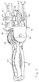
- Fig. 1 The distal shaft end 1 and the traction means guided by the shaft 2 are shown in the form of tension wires 3 - 8, which are guided through the shaft 2 to the proximal end and fastened there by levers, rollers or the like for the purpose of applying tensile forces ,
- the puller wires 3 and 4 serve to pivot the instrument head 9 relative to the distal shaft end 1 about a pivot axis 10.
- the puller wires 5 and 6 serve to pivot the in Fig. 1 shown upper jaw part 11 of a Pliers mouth, whose in Fig. 1 lower jaw part 12 is controllable by the puller wires 7 and 8 in its pivoting movement.
- the jaw parts 11 and 12 are pivotable about a common axis 13, which is arranged with respect to the instrument longitudinal axis 14 at a distance and rotated by 90 ° to the pivot axis 10.
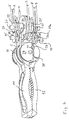
- the instrument head 9 has an intermediate piece 15, which is constructed of a circular in the outer contour of base 16 and from the distally two 180 ° relative to the longitudinal axis 14 staggered legs 17 and 18 extend, between which the jaws 11 and 12 pivotally mounted are, as well as proximally two diametrically arranged and relative to the axis 14 by 180 ° to each other staggered legs 19 and 20 which are relative to the axis 14 offset by 90 ° to the legs 17 and 18 are arranged. Both the legs 17 and 18 and the legs 19 and 20 are arranged near the outer periphery of the base body 16 and continue the circular cross-section of the shaft shape of the shaft 2 to the outside in these areas.
- the legs 19 and 20 are rotatably connected to a shaft 21 which is rotatably mounted in recesses of legs, which are provided at the distal end of the shaft 2.
- a cam plate 24 is fixed against rotation, over which the puller wires 3 and 4 extend, which are each fixed laterally in the disc with their ends.
- the shaft 21 carries laterally of the cam 24 still two spacers 25, which are formed integrally with the cam 24 and the shaft 21 in the described embodiment, but also can be rotatably seated on the shaft 21 in the manner of a washer. It is in this context in particular to the representations in the FIGS. 12-14 where this is shown in detail.
- the proximal-facing legs 19 and 20 of the intermediate piece 15 carry in the area between the shaft 21 and the main body 16 still three parallel axes, namely one, offset at a distance and parallel to the shaft 21, short axis 45 and two laterally offset thereto also arranged short Axes 26a and 27a.
- the axes 45, 26a and 27a are arranged parallel to the shaft 21, the central axes 45 are located in the direction of the longitudinal axis 14 of the instrument behind the shaft 21.
- the bores for the short axes 26a and 27a are by dummy pins 26b and 27b to the outside completed.
- holes the short axes 26 a and 27 a and 45 are incorporated in the intermediate piece 15, is based on Fig. 11 indicated by broken lines. In this case, for example, first insert the short axis 26a into the corresponding bore and then close it by the dummy pin 26b, as on the other side, first introduce the short axis 27a and then close it by the dummy pin
- the central axes 45 carry two pulleys 28 and 29, the short axes 26a and 27a each carry a pulley 30 and 31.
- the pulleys 28 - 31 are identical and freely rotatably mounted, they serve to deflect the puller wires 5-8 and act together with another four identical deflection rollers 32 - 35, which are rotatably mounted on the shaft 21 laterally of the spacers 25 in pairs.
- a pair of rollers each consisting of one of the deflection rollers 28 - 31 and a roller 21 arranged on the rollers 32 - 35 is formed for each of the puller wires 5-8.
- Each pair of rollers is arranged so that regardless of the pivotal position of the instrument head 9 to the shaft 2 of the wrap angle of a puller wire to a pair of rollers always constant is, ie, to the extent that reduces the wrap angle of a seated on the shaft 21 pulley 32 - 35, the wrap angle of the associated pulley 28 - 31 increases to a corresponding extent and vice versa.
- This arrangement causes the position of the puller wires 5 - 8 with respect to the pivotal position of the associated jaws 11 and 12 about the axis 13 is independent of the pivotal position of the instrument head 9 about the pivot axis 10.
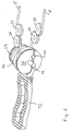
- the forceps jaw parts 11 and 12 are freely movably mounted about the rotation axis 13 and connected to two pull wires 5 and 6 or 7 and 8, wherein a pull wire for pivoting a jaw part in the opening direction and the other pull wire is provided for pivoting the jaw part in the closing direction. Since each jaw part 11 and 12 are each assigned two puller wires 5 and 6 or 7 and 8, the jaw parts 11 and 12 can not only be pivoted towards and away from each other but also together, so that the tool also deviates in a direction deviating from the longitudinal direction 14 Can take direction.
- each jaw part is connected to two cams, namely a large cam 36 arranged close to the longitudinal central axis 14 and a smaller cam disc 37 arranged next to it.
- the large cam 36 has a significantly larger radius than the small cam 37.
- Both cams are designed and arranged so that they are in the in Fig. 1 shown straight position with the forceps jaw closed by a pull wire 5 - 8 are wrapped by more than 90 °. They have an approximately in extension of the forceps jaw extending lateral recess 38 which is channel-like and is provided for receiving the Switzerlandseilendes. Transverse thereto, a bore 39 is provided in which a transverse pin 41 is arranged, in which the Switzerlandseilende is fixed.
- puller wires which move the respective forceps jaw part 11 or 12 towards the other forceps jaw part 12 or 11, ie act on the jaw part in the closing direction, are fixed to the large cam discs 36, which are close to the longitudinal center axis 14 approximately midway between the legs 17 and 18 are arranged.
- the smaller diameter cam plates 37 are connected to the Werdrähten the jaws 11 and 12, which serve to open the forceps jaw.
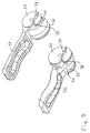
- the jaw members 11 and 12 with the associated cams 36 and 37 are identical in the illustrated embodiment, ie, it can find two identical components use.
- a clearance 40 is formed in the area of the cams between the large cam 36 and the smaller cam 37, which is dimensioned such that upon rotation of the component by 180 ° about the longitudinal axis of the large cam 36 of a jaw member 12 between the two cams 36, 37 of the other jaw part 11 can be incorporated.
- the two large cams 36 are each adjacent to the longitudinal center axis 14 and the smaller cams 37 at a distance next to it.
- the above-described instrument head can be pivoted by applying a tensile force to the pull wires 3 or 4 about the axis 10 in two directions.
- the forceps jaw can be opened by applying tensile forces to the tension wires 5 and 7, this is closed. If tensile forces are simultaneously applied to the tension wires 6 and 7 or 5 and 8, then both jaw parts pivot in the same direction about the axis 13 without changing their angular position relative to one another.
Landscapes
- Health & Medical Sciences (AREA)
- Surgery (AREA)
- Life Sciences & Earth Sciences (AREA)
- Engineering & Computer Science (AREA)
- Medical Informatics (AREA)
- Biomedical Technology (AREA)
- Heart & Thoracic Surgery (AREA)
- Nuclear Medicine, Radiotherapy & Molecular Imaging (AREA)
- Molecular Biology (AREA)
- Animal Behavior & Ethology (AREA)
- General Health & Medical Sciences (AREA)
- Public Health (AREA)
- Veterinary Medicine (AREA)
- Robotics (AREA)
- Ophthalmology & Optometry (AREA)
- Surgical Instruments (AREA)
Description
Die Erfindung betrifft ein endoskopisches Instrument gemäß den im O-berbegriff des Anspruchs 1 angegebenen Merkmalen.The invention relates to an endoscopic instrument according to the features specified in the O-term of claim 1.
Endoskopische Instrumente dieser Art, welche einen Instrumentenkopf mit einem Werkzeug mit zwei zueinander schwenkbaren Maulteilen aufweisen, werden heutzutage vielfältig eingesetzt, beispielsweise als Scheren, Zangen oder dergleichen. Dabei erfolgt die Bewegung der Maulteile durch Steuerung vom proximalen Instrumentenende aus, entweder über eine Handhabe manuell oder robotisch, d. h. durch eine entsprechende Steuerungsvorrichtung.Endoscopic instruments of this type, which have an instrument head with a tool with two mutually pivotable jaw parts, are now widely used, for example as scissors, forceps or the like. The movement of the jaw parts takes place by control of the proximal end of the instrument, either manually or robotically via a handle, d. H. by a corresponding control device.
Derartige Instrumente sind beispielsweise aus
Ungeachtet ob diese robotisch, d. h. mit elektromotorischer Ansteuerung oder aber manuell betätigt werden, ist ein wesentliches Kriterium für den Einsatz der Schaftdurchmesser. Je kleiner der Schaftdurchmesser ist, desto vielfältiger ist das Instrument einzusetzen, es kann durch enge natürliche oder durch den Operateur geschaffene Öffnungen zum Operationsfeld geführt werden.Regardless of whether these robotic, d. H. With electromotive control or manually operated, is an essential criterion for the use of the shaft diameter. The smaller the shaft diameter, the more diverse the instrument can be used, it can be guided by narrow natural or created by the surgeon openings to the surgical field.
Ein Nachteil dünner Schaftdurchmesser und damit einhergehend in der Regel auch dünner Instrumentenköpfe ist es, dass es konstruktiv schwierig ist, die erforderlichen Kräfte durch Betätigung am proximalen Ende im Werkzeug aufzubringen, dies um so mehr, wenn, was häufig erforderlich ist, der Instrumentenkopf schwenkbar gegenüber dem Schaft sein soll.A disadvantage of thinner shank diameters and consequently also of thinner instrument heads is that it is structurally difficult to apply the required forces by actuation at the proximal end in the tool, all the more so if what is often required is, the instrument head is to be pivotable relative to the shaft.
Vor diesem Stand der Technik (
Diese Aufgabe wird gemäß der Erfindung durch ein endoskopisches Instrument mit den in Anspruch 1 angegebenen Merkmalen gelöst. Vorteilhafte Ausgestaltungen der Erfindung ergeben sich aus den Unteransprüchen, der nachfolgenden Beschreibung und der Zeichnung.This object is achieved according to the invention by an endoscopic instrument having the features specified in claim 1. Advantageous embodiments of the invention will become apparent from the dependent claims, the following description and the drawings.
Das erfindungsgemäße endoskopische Instrument weist einen Schaft auf, an dessen distalen Ende ein Instrumentenkopf angeordnet ist, welcher ein Werkzeug mit vorzugsweise zwei zueinander schwenkbaren Maulteilen aufweist. Innerhalb des Schaftes sind Zugmittel vom proximalen Instrumentenende aus steuerbar, wobei jedes Maulteil zwei Kurvenscheiben aufweist, an denen je ein Zugmittel angreift. Gemäß der Erfindung sind jedem Maulteil zwei Kurvenscheiben unterschiedlicher radialer Größe zugeordnet, wobei jeweils die radial größere Kurvenscheibe näher der Längsmittelachse des Werkzeugs angeordnet ist als die radial kleinere Kurvenscheibe.The endoscopic instrument according to the invention has a shaft, on whose distal end an instrument head is arranged, which has a tool with preferably two mutually pivotable jaw parts. Within the shaft, traction means are controllable from the proximal end of the instrument, wherein each jaw part has two cams on each of which a traction means engages. According to the invention, each jaw part is associated with two cams of different radial size, wherein in each case the radially larger cam is arranged closer to the longitudinal center axis of the tool than the radially smaller cam.
Grundgedanke der erfindungsgemäßen Lösung ist, Kurvenscheiben unterschiedlicher radialer Größen zu verwenden und dabei die radial größeren Kurvenscheiben zentral nahe der Werkzeugachse und die radial kleineren weiter außen anzuordnen, um auf diese Weise den in der Regel sich auch im Werkzeugkopf fortsetzenden runden Schaftquerschnitt möglichst optimal auszunutzen. Dabei ist für die auf das jeweilige Maulteil aufzubringende Kraft der radiale Abstand der Kurvenscheibe zur Drehachse entscheidend, da dieser bei vorgegebener Kraft das Moment bestimmt, mit welchem das Maulteil bewegt werden kann. Dadurch ist beispielsweise bei einer Zange die maximale Schließkraft bestimmt oder bei einer Schere die Scherkraft. Durch die erfindungsgemäße Anordnung wird erreicht, dass in eine Schwenkrichtung eines Maulteils eine höhere Kraft als in andere Richtung aufgebracht werden kann, nämlich dort, wo die radial größere Kurvenscheibe Verwendung findet. In welche Richtung diese Kraft aufgebracht werden soll, ist im Wesentlichen vom Verwendungszweck abhängig. Soll beispielsweise mit den Maulteilen ein Hohlraum offengehalten oder gespreizt werden, so ist es zweckmäßig die radial größeren Kurvenscheiben zum Schwenken der Maulteile in Öffnungsstellung vorzusehen. Bei einer Zange oder Schere hingegeben, wird zweckmäßigerweise die höhere Kraft in Schließrichtung benötigt, weshalb es dann von Vorteil ist, die radial größeren Kurvenscheiben den Zugmitteln zuzuordnen, welche die Maulteile aufeinander zu bewegen.The basic idea of the solution according to the invention is to use cams of different radial sizes and thereby to arrange the radially larger cams centrally near the tool axis and the radially smaller further outwards in order in this way to continue the generally also in the tool head round shaft cross-section to use as optimally as possible. In this case, the radial distance between the cam disc and the axis of rotation is decisive for the force to be applied to the respective jaw part, since with a given force it determines the moment with which the jaw part can be moved. As a result, the maximum closing force is determined, for example, with a pair of pliers or the shear force in the case of a pair of scissors. By the arrangement according to the invention it is achieved that in a pivoting direction of a jaw member, a higher force than in the other direction can be applied, namely where the radially larger cam is used. The direction in which this force is to be applied depends essentially on the intended use. If, for example, a cavity is to be kept open or spread with the jaw parts, then it is expedient to provide the radially larger cam disks for pivoting the jaw parts in the open position. Given with a pair of pliers or scissors, the higher force in the closing direction is expediently required, which is why it is advantageous to assign the radially larger cams to the traction means which move the jaws towards each other.
Bei der vorbeschriebenen bevorzugten erfindungsgemäßen Lösung, bei welcher jedem Maulteil zwei Kurvenscheiben zugeordnet sind, kann neben dem Schließen und Öffnen der Maulteile im Weiteren eine Schwenkbewegung realisiert werden, welche einen zusätzlichen Freiheitsgrad gewährt, wenn beide Maulteile gleichzeitig in dieselbe Richtung geschwenkt werden.In the above-described preferred solution according to the invention, in which each jaw part associated with two cams, in addition to the closing and opening of the jaw parts further pivotal movement can be realized, which grants an additional degree of freedom when both jaws are pivoted simultaneously in the same direction.
Es versteht sich, dass das erfindungsgemäße Prinzip in einfachster Form mit einem schwenkbaren Maulteil und einem weiteren feststehenden Maulteil realisiert werden kann, dann sind für das schwenkbare Maulteil zwei Kurvenscheiben vorgesehen, nämlich eine radial größere Kurvenscheibe, welche nahe der Längsmittelachse oder im Bereich der Längsmittelachse des Werkzeugs angeordnet und eine radial kleinere Kurvenscheibe, welche daneben angeordnet ist, dort wo weniger Raum innerhalb des Schaftquerschnitts zur Verfügung steht.It is understood that the principle according to the invention can be realized in the simplest form with a pivotable jaw part and a further fixed jaw part, then two cams are provided for the pivotable jaw part, namely a radially larger cam, which near the longitudinal central axis or in the region of the longitudinal center axis of Tool arranged and a radially smaller Cam, which is arranged next to it, where less space is available within the shaft cross-section.
Bei Werkzeugen wie Zangen, Scheren und dergleichen, welche ihre größte Kraft in Schließrichtung aufbringen müssen, ist es vorteilhaft, wenn die radial größeren Kurvenscheiben den Zugmitteln zum Schließen und die radial kleineren Kurvenscheiben den Zugmitteln zum Öffnen der Maulteile zugeordnet sind. Die Öffnungskräfte können in der Regel um ein Vielfaches geringer sein, als die erforderlichen Schließkräfte, weshalb hier kleine Hebel, d. h. kleine Durchmesser der Kurvenscheibe ausreichen, um die erforderlichen Kräfte aufzubringen. Diese Kurvenscheiben, an denen die Zugmittel zum Öffnen der Maulteile angeordnet sind, können einen vergleichsweise kleinen Durchmesser haben und damit weiter außen angeordnet werden, während die radial größeren Kurvenscheiben, also die deren Kurvenbahn einen größeren radialen Abstand von der Drehachse aufweist, zentrumsnah angeordnet sind, dort wo der größte Freiraum bei den üblichen runden oder ovalen Instrumentendurchmesser gegeben ist.For tools such as pliers, shears and the like, which must apply their greatest force in the closing direction, it is advantageous if the radially larger cams are assigned to the traction means for closing and the radially smaller cams the traction means for opening the jaws. The opening forces can usually be many times lower than the required closing forces, which is why here small levers, d. H. small diameter of the cam sufficient to apply the required forces. These cams on which the traction means are arranged for opening the jaw parts, may have a comparatively small diameter and thus be arranged further out, while the radially larger cams, ie whose cam track has a greater radial distance from the axis of rotation are located close to the center, where the largest free space is given for the usual round or oval instrument diameter.
Grundsätzlich ist die Form der Kurvenscheiben frei wählbar. So kann beispielsweise durch eine elliptische Kurvenscheibe die Kraft beim Maulteil in bestimmten Stellungen gezielt erhöht werden. Dies kann beispielsweise sinnvoll sein, wenn nur ein Maulteil schwenkbeweglich ist, um die höchste Kraft unmittelbar vor oder in der Schließstellung zu erzielen. Bei der bevorzugten Ausführung, bei welcher beide Maulteile in beiden Richtungen schwenkbar sind und somit einen weiteren Freiheitsgrad des endoskopischen Instrumenten realisieren, ist es zweckmäßig und vorteilhaft, die Kurvenscheiben kreisförmig auszubilden und vorzugsweise mit ihrem Kreismittelpunkt auf der gemeinsamen Schwenkachse der Maulteile anzuordnen. Eine solche Anordnung gewährleistet bei vorgegebener Kraft am Zugmittel unabhängig von der Schwenkstellung stets das gleiche Moment am Maulteil, was grundsätzlich vorteilhaft ist.Basically, the shape of the cam discs is freely selectable. Thus, for example, by an elliptical cam, the force in the jaw part can be selectively increased in certain positions. This can be useful, for example, if only one jaw part is pivotable in order to achieve the highest force immediately before or in the closed position. In the preferred embodiment in which both jaw parts are pivotable in both directions and thus realize a further degree of freedom of the endoscopic instruments, it is expedient and advantageous to form the cams circular and preferably to arrange with their circle center on the common pivot axis of the jaw parts. Such an arrangement always ensures the same moment on the jaw part for a given force on the traction means regardless of the pivot position, which is basically advantageous.
Unter radialer Größe im Sinne der vorliegenden Erfindung ist der maximale radiale Abstand der Kurvenscheibe von ihrem Drehpunkt zu verstehen. D. h. die größere Kurvenscheibe ist stets die, die den größeren radialen Abstand von ihrem Drehpunkt aufweist, auch wenn diese möglicherweise schmaler ist oder in Teilbereichen einen geringeren radialen Abstand aufweist, als die andere Kurvenscheibe. Der maximale radiale Abstand bestimmt den erforderlichen Freiraum, der zur Anordnung der Kurvenscheibe erforderlich ist. Hier soll gemäß der Erfindung die größere Kurvenscheibe in der Längsmittelachse oder nahe der Längsmittelachse angeordnet sein und die kleinere weiter außen daneben.For the purposes of the present invention, radial size means the maximum radial spacing of the cam disk from its pivot point. Ie. the larger cam is always the one that has the greater radial distance from its fulcrum, even if it is possibly narrower or has a smaller radial distance in some areas than the other cam. The maximum radial distance determines the required clearance, which is required for the arrangement of the cam. Here is to be arranged according to the invention, the larger cam in the longitudinal center axis or near the longitudinal center axis and the smaller further outward next to it.
Vorteilhaft sind gemäß einer Weiterbildung der Erfindung die Zugmittel nicht um die Kurvenscheiben umlaufend sondern endseitig dort festgelegt und weisen einen Umschlingungswinkel von vorteilhaft mehr als 90° auf. Der Umschlingungswinkel von mehr als 90° gewährleistet, dass das jeweilige Maulteil auch um einen Winkel von 90° oder mehr schwenkbar ist, was von Vorteil ist.Advantageously, according to an embodiment of the invention, the traction means are not circumferentially around the cams but there fixed end and have a wrap angle of advantageously more than 90 °. The wrap angle of more than 90 ° ensures that the respective jaw part is also pivotable through an angle of 90 ° or more, which is an advantage.
Konstruktiv besonders günstig ist es, wenn ein Maulteil einstückig mit den zwei zugehörigen Kurvenscheiben ausgebildet ist. Hierdurch ist einerseits die erforderliche Momentenübertragung gewährleistet, andererseits kann ein solches Bauteil kostengünstig in einem Guss- oder anderem formgebenden Verfahren hergestellt werden.It is particularly advantageous in terms of construction if a jaw part is formed in one piece with the two associated cam disks. As a result, on the one hand ensures the required torque transmission, on the other hand, such a component can be produced inexpensively in a casting or other molding process.
Dabei ist es besonders vorteilhaft, wenn die beiden Maulteile identisch ausgebildet sind, wie dies beispielhaft im Ausführungsbeispiel weiter unten beschrieben ist. Eine solche Ausbildung hat den Vorteil, dass das Werkzeug mit zwei identischen Bauteilen aufgebaut werden kann, was die Herstellungskosten und Lagerhaltung verringert.It is particularly advantageous if the two jaws are formed identically, as described by way of example in the embodiment below. Such a design has the advantage that the tool can be constructed with two identical components, which reduces the manufacturing costs and storage.
Um dem Instrument einen weiteren Freiheitsgrad hinsichtlich der Bewegbarkeit des Instrumentenkopfes zu geben, ist gemäß einer vorteilhaften Weiterbildung der Erfindung ein Zwischenstück vorgesehen, in welchem die Maulteile gelagert sind und welches Teil des Instrumentenkopfes bildet und schwenkbar am distalen Schaftende angeordnet ist. Ein solches Zwischenstück kann entweder die Schwenkbarkeit der Maulteile weiter erhöhen, wenn beispielsweise die Schwenkachse des Zwischenstückes parallel zur Schwenkachse der Maulteile ist. Besonders vorteilhaft wird es jedoch in der Regel sein, wenn die Schwenkachse des Zwischenstücks mit Abstand und quer zur Schwenkachse der Maulteile angeordnet ist, wodurch eine Schwenkbewegung des Instrumentenkopfes quer zur Schwenkachse des Werkzeugs möglich ist, was die Freiheitsgrade bei der Bewegung des Werkzeugskopfes erhöht und somit die Vielseitigkeit des Instrumentes bei der Anwendung verbessert.In order to give the instrument a further degree of freedom with respect to the mobility of the instrument head, an intermediate piece is provided according to an advantageous development of the invention, in which the jaw parts are mounted and which forms part of the instrument head and is pivotally mounted on the distal shaft end. Such an intermediate piece can either further increase the pivotability of the jaw parts if, for example, the pivot axis of the intermediate piece is parallel to the pivot axis of the jaw parts. However, it will usually be particularly advantageous if the pivot axis of the intermediate piece is arranged at a distance and transversely to the pivot axis of the jaw parts, whereby a pivoting movement of the instrument head transverse to the pivot axis of the tool is possible, which increases the degrees of freedom in the movement of the tool head and thus improves the versatility of the instrument during use.
Vorteilhaft ist gemäß einer Weiterbildung der Erfindung vorgesehen, dass das Zwischenstück aus einem Grundkörper aufgebaut ist, von dem sich zwei zueinander beabstandete Schenkel distalwärts erstrecken, welche die Maulteile mit ihrer Schwenkachse aufnehmen und von dem sich in Achsrichtung als in Richtung der Längsachse um 90° versetzt dazu zwei zueinander beabstandete Schenkel proximalwärts erstrecken, welche die Schwenkachse des Zwischenstücks und die drauf angeordneten Bauteile aufnehmen. Dabei weist der Grundkörper typischerweise einer kreisrunde Außenkontur auf, welche der Schaftkontur vorteilhaft entspricht, wohingegen die Schenkel der Schaftkontur folgend jeweils an zwei etwa um 180° versetzten Stellen nahe dem Außenumfang des Grundkörper ansetzen.Advantageously, according to a development of the invention, it is provided that the intermediate piece is constructed from a base body, from which two distantly spaced legs extend distally, which receive the jaw members with their pivot axis and offset from the axis in the direction of the longitudinal axis by 90 ° to extend two spaced apart legs proximally, which receive the pivot axis of the intermediate piece and the components arranged thereon. In this case, the base body typically has a circular outer contour, which advantageously corresponds to the shank contour, whereas the shanks following the shank contour adjoin the outer circumference of the main body respectively at two points offset by approximately 180 °.
Um das Zwischenstück gegenüber dem Instrumentenschaft in seiner Schwenkbewegung mit Zugmitteln steuern zu können, ist es vorteilhaft, wenn die proximalwärts gerichteten Schenkel des Zwischenstücks drehfest mit einer Welle verbunden sind, auf der wiederum drehfest eine Kurvenscheibe angeordnet ist, an welcher Zugmittel zur Steuerung der Schwenkstellung des Zwischenstücks angreifen, welche durch den Schaft zum proximalen Instrumentenende führen. Dabei können mit der Welle ein oder zwei Kurvenscheiben verbunden sein, je nachdem ob für jedes Zugmittel eine Kurvenscheibe vorgesehen werden soll oder, was besonders vorteilhaft ist, beide Zugmittel an einer Kurvenscheibe angreifen, die dann mittig innerhalb des Bereiches der Längsachse angeordnet werden kann, in welchem aufgrund der Querschnittskontur der größte Freiraum gegeben ist.In order to control the intermediate piece with respect to the instrument shaft in its pivoting movement with traction means, it is advantageous if the proximally directed legs of the intermediate piece are rotatably connected to a shaft, on which in turn rotatably Cam is arranged on which pulling means for controlling the pivotal position of the intermediate piece attack, which lead through the shaft to the proximal end of the instrument. One or two cams may be connected to the shaft, depending on whether for each traction means a cam is to be provided or, which is particularly advantageous, both traction means engage a cam, which can then be arranged centrally within the range of the longitudinal axis, in which is given due to the cross-sectional contour of the largest free space.
Um die Zugmittel zur Bewegung der Maulteile durch das Gelenk am Instrumentenkopf zu führen, ist es vorteilhaft zwischen dem proximalwärts gerichteten Schenkeln für jedes zu einem Maulteil führenden Zugmittel ein Umlenkrollenpaar drehbar gelagert anzuordnen, und zwar so, dass eine der Umlenkrollen auf der Welle, deren Achse die Schwenkachse des Gelenks bildet und die andere versetzt dazu zwischen Welle und Grundkörper angeordnet ist. Eine solche Umlenkrollenführung ist von der Kraftübertragung besonders günstig, da die durch das Zugmittel aufgebrachte Kraft mit nur wenigen Verlusten durch das Gelenk hindurch zu den Maulteilen übertragen werden kann. Eine solche Rollenführung ist stets reibungsärmer als z. B. eine Bowdenzuganordnung. Sie kann darüber hinaus auch über Schwenkbereiche Verwendung finden, die über 90° hinausgehen.In order to guide the traction means for moving the jaw parts through the joint on the instrument head, it is advantageous to arrange a deflection roller pair rotatably mounted between the proximally directed legs for each traction means leading to a jaw part, such that one of the deflection rollers on the shaft whose axis forms the pivot axis of the joint and the other offset is arranged between the shaft and the base body. Such Umlenkrollenführung is particularly favorable from the power transmission, since the force applied by the traction means with only a few losses through the joint can be transmitted to the jaws. Such a roller guide is always friction poorer than z. B. a Bowden cable assembly. In addition, it can be used over swivel ranges that go beyond 90 °.
Eine besonders vorteilhafte Weiterbildung des erfindungsgemäßen Instrumentes ergibt sich, wenn jedes Umlenkrollenpaar so angeordnet wird, dass der Umschlingungswinkel des zugehörigen Zugmittels um das Umlenkrollenpaar unabhängig von der Schwenkstellung des Zwischenstücks ist. Dann hat ein Verschwenken des Zwischenstücks, d. h. ein Verschwenken des Instrumentenkopfes in Bezug auf den Instrumentenschaft keinerlei Einfluss auf die Werkzeugbewegung und die Werkzeugkräfte. Dies ist insbesondere bei manueller Betätigung des Instrumentes vorteilhaft aber auch bei robotischer Anbindung, da keine Bewegungskompensation erforderlich ist, was Rechen- und Motorkapazität erfordert.A particularly advantageous development of the instrument according to the invention results when each deflection roller pair is arranged such that the wrap angle of the associated traction means around the deflection roller pair is independent of the pivot position of the intermediate piece. Then, a pivoting of the intermediate piece, ie, a pivoting of the instrument head with respect to the instrument shaft has no influence on the tool movement and the tool forces. This is especially true with manual operation of the instrument advantageous but also with robotic connection, since no motion compensation is required, which requires computing and engine capacity.
Die Erfindung ist nachfolgend anhand eines in der Zeichnung dargestellten Ausführungsbeispiels näher erläutert. Es zeigen
- Fig. 1
- in vereinfachter perspektivischer Darstellung das distale Schaftende mit Instrumentenkopf und den durch den Schaft führenden Zugmitteln,
- Fig. 2
- eine perspektivische Ansicht des distalen Instrumentenkopfes ohne Schaft,
- Fig. 3
- eine Ansicht des Instrumentenkopfes ohne Zwischenstück und Schaft,
- Fig. 4
- eine gegenüber
Fig. 3 um 90° um die Längsachse gedrehte Darstellung, - Fig. 5
- in schematischer Darstellung das in
Fig. 1 obere Maulteil mit den daran angebundenen Zugmitteln, - Fig. 6
- das in
Fig. 1 dargestellte untere Maulteil mit den daran angebundenen Zugmitteln, - Fig. 7
- in perspektivischer Explosionsdarstellung die beiden Maulteile,
- Fig. 8
- eine Ansicht auf das Schaftende mit Zwischenstück ohne Umlenkrollen und Maulteile,
- Fig. 9
- eine gegenüber
Fig. 8 um 90° gedrehte Ansicht, - Fig. 10
- eine Schnitt längs der Schnittlinie X-X in
Fig. 9 , - Fig. 11
- in vergrößerter perspektivischer Darstellung das Zwischenstück,
- Fig. 12
- in perspektivischer Darstellung die Kurvenscheibe mit Welle und Zugmitteln zur Schwenkbewegung des Instrumentenkopfes,
- Fig. 13
- eine Seitenansicht quer zur Schwenkachse der Bauteile gemäß
Fig. 12 und - Fig. 14
- eine Seitenansicht in Richtung der Schwenkachse.
- Fig. 1
- in a simplified perspective view of the distal end of the shaft with the instrument head and the pulling means passing through the shaft,
- Fig. 2
- a perspective view of the distal instrument head without shank,
- Fig. 3
- a view of the instrument head without adapter and shaft,
- Fig. 4
- one opposite
Fig. 3 rotated by 90 ° about the longitudinal axis representation, - Fig. 5
- in schematic representation the in
Fig. 1 upper jaw part with the traction means attached thereto, - Fig. 6
- this in
Fig. 1 illustrated lower jaw part with the traction means connected thereto, - Fig. 7
- in a perspective exploded view of the two jaw parts,
- Fig. 8
- a view of the shaft end with intermediate piece without pulleys and jaws,
- Fig. 9
- one opposite
Fig. 8 90 ° rotated view, - Fig. 10
- a section along the section line XX in
Fig. 9 . - Fig. 11
- in an enlarged perspective view of the intermediate piece,
- Fig. 12
- in a perspective view the cam with shaft and traction means for pivotal movement of the instrument head,
- Fig. 13
- a side view transverse to the pivot axis of the components according to
Fig. 12 and - Fig. 14
- a side view in the direction of the pivot axis.
Von dem erfindungsgemäßen endoskopischen Instrument ist im Folgenden nur der distale Instrumententeil beschrieben und dargestellt. Der langgestreckte Schaft sowie die proximale Ausgestaltung, sei es als Handhabe zur unmittelbaren manuellen Betätigung durch den Operateur oder als robotischer Anschluss wie es bei dem aus
In
Alle im Folgenden gemachten Angaben bezogen auf die Längsachse 14 des Instrumentes beziehen sich auf die in
Der Instrumentenkopf 9 weist ein Zwischenstück 15 auf, das aus einem in der Außenkontur kreisrunden Grundkörper 16 aufgebaut ist und von dem sich distalwärts zwei um 180° bezogen auf die Längsachse 14 versetzte Schenkel 17 und 18 erstrecken, zwischen denen die Maulteile 11 und 12 schwenkbar gelagert sind, sowie proximalwärts zwei ebenfalls diametral angeordnete und bezogen auf die Achse 14 um 180° zueinander versetzt angeordnete Schenkel 19 und 20, die bezogen auf die Achse 14 um 90° versetzt zu den Schenkeln 17 und 18 angeordnet sind. Sowohl die Schenkel 17 und 18 als auch die Schenkel 19 und 20 sind nahe dem Außenumfang des Grundkörpers 16 angeordnet und setzen die im Querschnitt kreisrunde Schaftform des Schaftes 2 nach außen hin in diesen Bereichen fort.The
Die Schenkel 19 und 20 sind drehfest mit einer Welle 21 verbunden, welche drehbar in Ausnehmungen von Schenkeln gelagert, die am distalen Ende des Schaftes 2 vorgesehen sind. Auf der Welle 21 ist drehfest eine Kurvenscheibe 24 befestigt, über welche die Zugdrähte 3 und 4 verlaufen, die jeweils seitlich in der Scheibe mit ihren Enden festgelegt sind. Die Welle 21 trägt seitlich der Kurvenscheibe 24 noch zwei Distanzscheiben 25, die in der beschriebenen Ausführung einstückig mit der Kurvenscheibe 24 und der Welle 21 ausgebildet sind, die jedoch auch nach Art einer Unterlegscheibe drehbar auf der Welle 21 sitzen können. Es wird in diesem Zusammenhang insbesondere auf die Darstellungen in den
Die proximalwärts weisenden Schenkel 19 und 20 des Zwischenstücks 15 tragen im Bereich zwischen der Welle 21 und dem Grundkörper 16 noch drei parallele Achsen, nämlich eine, mit Abstand versetzt und parallel zur Welle 21, kurze Achse 45 sowie zwei jeweils seitlich versetzt dazu angeordnete ebenfalls kurze Achsen 26a und 27a. Die Achsen 45, 26a und 27a sind parallel zur Welle 21 angeordnet, die zentralen Achsen 45 liegen in Richtung der Längsachse 14 des Instrumentes gesehen hinter der Welle 21. Die Bohrungen für die kurzen Achsen 26a und 27a sind durch Blindstifte 26b bzw. 27b nach außen hin abgeschlossen. In welche Bohrungen die kurzen Achsen 26a und 27a sowie 45 in dem Zwischenstück 15 eingegliedert werden, ist anhand von
Die zentralen Achsen 45 tragen zwei Umlenkrollen 28 und 29, die kurzen Achsen 26a und 27a tragen jeweils eine Umlenkrolle 30 bzw. 31. Die Umlenkrollen 28 - 31 sind baugleich und frei drehbar gelagert, sie dienen zum Umlenken der Zugdrähte 5 - 8 und wirken zusammen mit weiteren vier baugleichen Umlenkrollen 32 - 35, die drehbar auf der Welle 21 seitlich der Distanzscheiben 25 jeweils paarweise gelagert sind. Dabei ist für jeden der Zugdrähte 5 - 8 ein Rollenpaar jeweils bestehend aus einer der Umlenkrollen 28 - 31 sowie einer auf der Welle 21 angeordneten Rollen 32 - 35 gebildet. Jedes Rollenpaar ist so angeordnet, dass unabhängig der Schwenkstellung des Instrumentenkopfes 9 zum Schaft 2 der Umschlingungswinkel eines Zugdrahtes um ein Rollenpaar stets konstant ist, d. h. in dem Maße, wie sich der Umschlingungswinkel einer auf der Welle 21 sitzenden Umlenkrolle 32 - 35 verringert, so vergrößert sich der Umschlingungswinkel der zugehörigen Umlenkrolle 28 - 31 in entsprechendem Maße und umgekehrt. Diese Anordnung bewirkt, dass die Stellung der Zugdrähte 5 - 8 bezogen auf die Schwenkstellung der damit verbundenen Maulteile 11 und 12 um die Achse 13 unabhängig von der Schwenkstellung des Instrumentenkopfes 9 um die Schwenkachse 10 ist.The
Die Zangenmaulteile 11 und 12 sind frei beweglich um die Drehachse 13 gelagert und jeweils mit zwei Zugdrähten 5 und 6 bzw. 7 und 8 verbunden, wobei ein Zugdraht zum Schwenken eines Maulteils in Öffnungsrichtung und der andere Zugdraht zum Schwenken des Maulteils in Schließrichtung vorgesehen ist. Da jedem Maulteil 11 und 12 jeweils zwei Zugdrähte 5 und 6 bzw. 7 und 8 zugeordnet sind, können die Maulteile 11 und 12 nicht nur aufeinander zu und voneinander weg sondern auch gemeinsam geschwenkt werden, sodass das Werkzeug auch in einer von der Längsrichtung 14 abweichenden Richtung greifen kann.The
Hierzu ist jedes Maulteil mit zwei Kurvenscheiben verbunden, nämlich mit einer nahe der Längsmittelachse 14 angeordneten großen Kurvenscheibe 36 und einer daneben angeordneten kleineren Kurvenscheibe 37. Die große Kurvenscheibe 36 weist einen deutlich größeren Radius als die kleine Kurvenscheibe 37 auf. Beide Kurvenscheiben sind so ausgebildet und angeordnet, dass sie in der in
Bei der dargestellten Ausführungsform sind Zugdrähte, welche das jeweilige Zangenmaulteil 11 bzw. 12 auf das andere Zangenmaulteil 12 bzw. 11 zubewegen, d. h. das Maulteil in Schließrichtung beaufschlagen, an den großen Kurvenscheiben 36 festgelegt, die nahe der Längsmittelachse 14 etwa mittig zwischen den Schenkeln 17 und 18 angeordnet sind. Die im Durchmesser kleineren Kurvenscheiben 37 sind mit den Zugdrähten der Maulteile 11 und 12 verbunden, die zum Öffnen des Zangenmauls dienen. Durch diese Anordnung ist es möglich, bei gleicher Zugkraft auf die Zugdrähte 5 und 6 bzw. 7 und 8 eine höhere Kraft der Zangenmaulteile 11 und 12 in Schließrichtung des Mauls als in Öffnungsrichtung zu erzeugen, da aufgrund des größeren Radius der großen Kurvenscheiben 36 dort ein größeres Moment erzeugt wird, als bei gleichgroßer Krafteinleitung auf die kleineren Umlenkscheiben 37 erzeugt wird. Wie insbesondere die
Wie insbesondere die
Der vorbeschriebene Instrumentenkopf kann durch Aufbringen einer Zugkraft an den Zugdrähten 3 oder 4 um die Achse 10 in zwei Richtungen geschwenkt werden. Durch Aufbringen von Zugkräften an den Zugdrähten 6 und 8 kann das Zangenmaul geöffnet werden, durch Aufbringen von Zugkräften an den Zugdrähten 5 und 7 wird dieses geschlossen. Werden Zugkräfte an den Zugdrähten 6 und 7 bzw. 5 und 8 gleichzeitig aufgebracht, so schwenken beide Maulteile in dieselbe Richtung um die Achse 13 ohne ihre Winkelstellung zueinander zu verändern.The above-described instrument head can be pivoted by applying a tensile force to the
- 11
- distales Schaftendedistal shaft end
- 22
- Schaftshaft
- 33
- Zugdrahtpull wire
- 44
- Zugdrahtpull wire
- 55
- Zugdrahtpull wire
- 66
- Zugdrahtpull wire
- 77
- Zugdrahtpull wire
- 88th
- Zugdrahtpull wire
- 99
- Instrumentenkopfinstrument head
- 1010
- Schwenkachseswivel axis
- 1111
-
oberes Maulteil in
Fig. 1 upper jaw part inFig. 1 - 1212
-
unteres Maulteil in
Fig. 1 lower jaw part inFig. 1 - 1313
- Schwenkachse der MaulteileSwivel axis of the jaw parts
- 1414
-
Längsachse des Instruments in Ausgangslage gemäß
Fig. 1 , SchaftachseLongitudinal axis of the instrument in starting position according toFig. 1 , Shaft axis - 1515
- Zwischenstückconnecting piece
- 1616
- Grundkörper von 15Basic body of 15
- 1717
- distalwärts gerichteter Schenkeldistally directed leg
- 1818
- distalwärts gerichteter Schenkeldistally directed leg
- 1919
- proximalwärts gerichteter SchenkelProximal directed thigh
- 2020
- proximalwärts gerichteter SchenkelProximal directed thigh
- 2121
- Wellewave
- 2222
- Schenkel am distalen SchaftendeLegs at the distal end of the shaft
- 2323
- Schenkel am distalen SchaftendeLegs at the distal end of the shaft
- 2424
- Kurvenscheibecam
- 2525
- Distanzscheibenspacers
- 26a26a
- kurze Achseshort axis
- 26b26b
- Blindstiftdummy pin
- 27a27a
- kurze Achseshort axis
- 27b27b
- Blindstiftdummy pin
- 2828
- Umlenkrollenguide rollers
- 2929
- Umlenkrollenguide rollers
- 3030
- Umlenkrollenguide rollers
- 3131
- Umlenkrollenguide rollers
- 3232
-
Umlenkrollen auf Welle 21Pulleys on
shaft 21 - 3333
-
Umlenkrollen auf Welle 21Pulleys on
shaft 21 - 3434
-
Umlenkrollen auf Welle 21Pulleys on
shaft 21 - 3535
-
Umlenkrollen auf Welle 21Pulleys on
shaft 21 - 3636
- große Kurvenscheibebig cam
- 3737
- kleine Kurvenscheibesmall cam
- 3838
- kanalartige Ausnehmungchannel-like recess
- 3939
- Querbohrungcross hole
- 4040
- Freiraum zwischen den KurvenscheibenFree space between the cams
- 4141
- durchbohrter Querstiftpierced cross pin
- 4545
- zentrale kurze Achsencentral short axes
Claims (12)
- An endoscopic instrument with a shank (2) and with an instrument head (9) which is arranged at the distal shank end (1) and which comprises a tool with two jaw parts (11, 12) which are pivotable to one another and which can be controlled from the proximal instrument end via pull means (5-8) led in the shank (2), wherein at least one jaw part (11, 12) comprises two curved disks (36, 37), on which a pull means (5-8) engages in each case, characterised in that two curved disks (36, 37) of a different radial size are assigned to at least one jaw part (11, 12), wherein the radially larger curved disk (36) is arranged closer to the longitudinal middle axis (14) of the tool than the radially smaller curved disk (37).
- An instrument according to claim 1, characterised in that the radially larger curved disk (36) is assigned to the pull means (6, 8) for the closure, and the radially smaller curved disk (37) to the pull means (5, 7) for opening the jaw part (11, 12).
- An instrument according to claim 1 or 2, characterised in that the curved disks (36, 37) are preferably designed in a circular manner and are arranged on the common pivot (13) of the jaw parts (11, 12).
- An instrument according to one of the preceding claims, characterised in that the pull means (5 - 8) are each fastened on the curved disks (36, 37) and wrap around these by more than 90°.
- An instrument according to one of the preceding claims, characterised in that a jaw part (11, 12) is designed as one piece with the two associated curved disks (36, 37).
- An instrument according to one of the preceding claims, characterised in that the two jaw parts (11, 12) are designed in an identical manner.
- An instrument according to one of the preceding claims, characterised in that the jaw parts (11, 12) are mounted in an intermediate piece (15) which forms part of the instrument head (9) and which is pivotably arranged about a pivot axis (10), at the distal shank end (1).
- An instrument according to claim 7, characterised in that the pivot axis (10) of the intermediate piece (15) is arranged at a distance and transversely to the pivot axis (13) of the jaw parts (11, 12).
- An instrument according to claim 7 or 8, characterised in that the intermediate piece (15) comprises a base body (16), from which two limbs (17, 18) receiving the jaw parts (11, 12) with their pivot axis (13) extend distally, and from which two limbs (19, 20) receiving the pivot axis (10) of the intermediate piece (15) and components (24, 25) arranged thereon, extend proximally in the axis direction (14) offset by 90° thereto.
- An instrument according to claim 9, characterised in that the proximally directed limbs (19, 20) are connected to a shaft (21) in a rotationally fixed manner, wherein a curved disk (24), on which pull means (3, 4) engage for the control of the pivot position of the intermediate piece (15), is arranged on said shaft (21) in a rotationally fixed manner.
- An instrument according to claim 10, characterised in that a deflection roller pair (28 - 35) is rotatably mounted between the proximally directed limbs (19, 20), for each pull means (5 -8) leading to a jaw part (11, 12), of which deflection roller pairs in each case one deflection roller (32 - 35) is arranged on the shaft (21) and the other (28-31) is arranged offset thereto between the shaft (21) and the base body (16).
- An instrument according to claim 11, characterised in that each deflection roller pair (28 -35) is arranged to one another such that the wrap angle of the associated pull means (5 - 8) about the deflection roller pair (28 - 35) is independent of the pivot position of the intermediate piece (15).
Applications Claiming Priority (2)
| Application Number | Priority Date | Filing Date | Title |
|---|---|---|---|
| DE201210212510 DE102012212510B4 (en) | 2012-07-17 | 2012-07-17 | Endoscopic instrument |
| PCT/EP2013/063865 WO2014012780A1 (en) | 2012-07-17 | 2013-07-01 | Endoscopic instrument |
Publications (2)
| Publication Number | Publication Date |
|---|---|
| EP2874548A1 EP2874548A1 (en) | 2015-05-27 |
| EP2874548B1 true EP2874548B1 (en) | 2016-06-01 |
Family
ID=48790373
Family Applications (1)
| Application Number | Title | Priority Date | Filing Date |
|---|---|---|---|
| EP13736817.1A Active EP2874548B1 (en) | 2012-07-17 | 2013-07-01 | Endoscopic instrument |
Country Status (5)
| Country | Link |
|---|---|
| US (1) | US9615846B2 (en) |
| EP (1) | EP2874548B1 (en) |
| CN (1) | CN104470450B (en) |
| DE (1) | DE102012212510B4 (en) |
| WO (1) | WO2014012780A1 (en) |
Cited By (1)
| Publication number | Priority date | Publication date | Assignee | Title |
|---|---|---|---|---|
| CN106826904A (en) * | 2017-01-23 | 2017-06-13 | 哈尔滨工业大学 | Using the dual input shaft gear ratio joint of steel wire drive |
Families Citing this family (81)
| Publication number | Priority date | Publication date | Assignee | Title |
|---|---|---|---|---|
| US8814921B2 (en) | 2008-03-06 | 2014-08-26 | Aquabeam Llc | Tissue ablation and cautery with optical energy carried in fluid stream |
| US9232959B2 (en) | 2007-01-02 | 2016-01-12 | Aquabeam, Llc | Multi fluid tissue resection methods and devices |
| US9339341B2 (en) | 2010-02-08 | 2016-05-17 | Intuitive Surgical Operations, Inc. | Direct pull surgical gripper |
| US10092359B2 (en) | 2010-10-11 | 2018-10-09 | Ecole Polytechnique Federale De Lausanne | Mechanical manipulator for surgical instruments |
| WO2013014621A2 (en) | 2011-07-27 | 2013-01-31 | Ecole Polytechnique Federale De Lausanne (Epfl) | Mechanical teleoperated device for remote manipulation |
| CN108606773B (en) | 2012-02-29 | 2020-08-11 | 普罗赛普特生物机器人公司 | Automated image-guided tissue ablation and treatment |
| US10231867B2 (en) | 2013-01-18 | 2019-03-19 | Auris Health, Inc. | Method, apparatus and system for a water jet |
| WO2014201165A1 (en) | 2013-06-11 | 2014-12-18 | Auris Surgical Robotics, Inc. | System for robotic assisted cataract surgery |
| US10426661B2 (en) | 2013-08-13 | 2019-10-01 | Auris Health, Inc. | Method and apparatus for laser assisted cataract surgery |
| JP6554794B2 (en) * | 2014-01-29 | 2019-08-07 | 住友ベークライト株式会社 | Medical equipment |
| US10265129B2 (en) | 2014-02-03 | 2019-04-23 | Distalmotion Sa | Mechanical teleoperated device comprising an interchangeable distal instrument |
| US10226305B2 (en) | 2014-02-12 | 2019-03-12 | Covidien Lp | Surgical end effectors and pulley assemblies thereof |
| EP3104792B1 (en) * | 2014-02-12 | 2022-06-15 | Covidien LP | Surgical end effectors and pulley assemblies thereof |
| EP3104791B1 (en) * | 2014-02-12 | 2022-04-27 | Covidien LP | Surgical end effectors and pulley assemblies thereof |
| DE102014205159A1 (en) * | 2014-03-19 | 2015-09-24 | Richard Wolf Gmbh | robot system |
| EP3185808B1 (en) | 2014-08-27 | 2022-02-23 | DistalMotion SA | Surgical system for microsurgical techniques |
| DE102014217796A1 (en) * | 2014-09-05 | 2016-03-10 | Richard Wolf Gmbh | Instrument, in particular medical endoscopic instrument or technoscope |
| DE102014224268B4 (en) * | 2014-11-27 | 2019-05-16 | Deutsches Zentrum für Luft- und Raumfahrt e.V. | Endoscopic instrument and method for grasping structures |
| EP3232977B1 (en) | 2014-12-19 | 2020-01-29 | DistalMotion SA | Docking system for mechanical telemanipulator |
| EP4342412A3 (en) | 2014-12-19 | 2024-06-05 | DistalMotion SA | Reusable surgical instrument for minimally invasive procedures |
| ES2968221T3 (en) | 2014-12-19 | 2024-05-08 | Distalmotion Sa | Surgical instrument with articulated end effector |
| US10548680B2 (en) | 2014-12-19 | 2020-02-04 | Distalmotion Sa | Articulated handle for mechanical telemanipulator |
| EP3232973B1 (en) | 2014-12-19 | 2020-04-01 | DistalMotion SA | Sterile interface for articulated surgical instruments |
| KR102153407B1 (en) * | 2015-02-17 | 2020-09-08 | 주식회사 리브스메드 | Surgical instrument |
| US20160287279A1 (en) | 2015-04-01 | 2016-10-06 | Auris Surgical Robotics, Inc. | Microsurgical tool for robotic applications |
| US10568709B2 (en) | 2015-04-09 | 2020-02-25 | Distalmotion Sa | Mechanical teleoperated device for remote manipulation |
| WO2016162751A1 (en) | 2015-04-09 | 2016-10-13 | Distalmotion Sa | Articulated hand-held instrument |
| US9883858B1 (en) * | 2015-06-15 | 2018-02-06 | Ethicon Endo-Surgery, Llc | Suturing instrument with robotic drive interface |
| WO2017037532A1 (en) | 2015-08-28 | 2017-03-09 | Distalmotion Sa | Surgical instrument with increased actuation force |
| ITUB20154977A1 (en) * | 2015-10-16 | 2017-04-16 | Medical Microinstruments S R L | Medical instrument and method of manufacture of said medical instrument |
| US10231793B2 (en) | 2015-10-30 | 2019-03-19 | Auris Health, Inc. | Object removal through a percutaneous suction tube |
| US9955986B2 (en) | 2015-10-30 | 2018-05-01 | Auris Surgical Robotics, Inc. | Basket apparatus |
| US9949749B2 (en) | 2015-10-30 | 2018-04-24 | Auris Surgical Robotics, Inc. | Object capture with a basket |
| GB201521809D0 (en) * | 2015-12-10 | 2016-01-27 | Cambridge Medical Robotics Ltd | Symmetrically arranged surgical instrument articulation |
| CN105496512B (en) * | 2015-12-14 | 2017-12-19 | 李强 | Refer to directly control more and turn wrist surgical forceps for abdominoscope |
| JPWO2017208320A1 (en) * | 2016-05-31 | 2019-03-22 | オリンパス株式会社 | Grip mechanism and gripper |
| US10869682B2 (en) * | 2016-07-08 | 2020-12-22 | Covidien Lp | Cutting mechanisms for surgical end effector assemblies, instruments, and systems |
| GB2554915B (en) * | 2016-10-14 | 2022-03-02 | Cmr Surgical Ltd | Driving arrangement for articulating a surgical instrument |
| CN106737828B (en) * | 2017-01-22 | 2019-01-22 | 哈尔滨工业大学 | Steel wire drive gear ratio cradle head for robot |
| US10792466B2 (en) | 2017-03-28 | 2020-10-06 | Auris Health, Inc. | Shaft actuating handle |
| US10285574B2 (en) | 2017-04-07 | 2019-05-14 | Auris Health, Inc. | Superelastic medical instrument |
| WO2018187069A1 (en) | 2017-04-07 | 2018-10-11 | Auris Surgical Robotics, Inc. | Patient introducer alignment |
| IT201700041991A1 (en) | 2017-04-14 | 2018-10-14 | Medical Microinstruments Spa | ROBOTIC ASSEMBLY FOR MICROSURGERY |
| US11058503B2 (en) | 2017-05-11 | 2021-07-13 | Distalmotion Sa | Translational instrument interface for surgical robot and surgical robot systems comprising the same |
| GB2563233B (en) * | 2017-06-06 | 2022-09-14 | Cmr Surgical Ltd | Pulley arrangement and pulley guard for articulating a surgical instrument |
| CN111885979A (en) | 2018-02-07 | 2020-11-03 | 迪斯透莫森公司 | Surgical robotic system including robotic telemanipulator and integrated laparoscopy |
| US11439376B2 (en) | 2018-03-07 | 2022-09-13 | Intuitive Surgical Operations, Inc. | Low-friction, small profile medical tools having easy-to-assemble components |
| US11992286B2 (en) | 2018-03-07 | 2024-05-28 | Intuitive Surgical Operations, Inc. | Low-friction medical tools having roller-assisted tension members |
| WO2019218157A1 (en) * | 2018-05-15 | 2019-11-21 | 深圳市亚泰光电技术有限公司 | Endoscope steering adjustment method and endoscope |
| JP7267309B2 (en) | 2018-06-07 | 2023-05-01 | オーリス ヘルス インコーポレイテッド | Robotic medical system with high-strength instruments |
| JP2020002966A (en) * | 2018-06-26 | 2020-01-09 | 川崎重工業株式会社 | Rotary actuator and robot forceps |
| US11399905B2 (en) | 2018-06-28 | 2022-08-02 | Auris Health, Inc. | Medical systems incorporating pulley sharing |
| US11259798B2 (en) | 2018-07-16 | 2022-03-01 | Intuitive Surgical Operations, Inc. | Medical devices having tissue grasping surfaces and features for manipulating surgical needles |
| US11612447B2 (en) | 2018-07-19 | 2023-03-28 | Intuitive Surgical Operations, Inc. | Medical devices having three tool members |
| CN112566584A (en) * | 2018-08-15 | 2021-03-26 | 奥瑞斯健康公司 | Medical instrument for tissue cauterization |
| WO2020036686A1 (en) | 2018-08-17 | 2020-02-20 | Auris Health, Inc. | Bipolar medical instrument |
| US11864849B2 (en) | 2018-09-26 | 2024-01-09 | Auris Health, Inc. | Systems and instruments for suction and irrigation |
| WO2020076447A1 (en) | 2018-10-08 | 2020-04-16 | Auris Health, Inc. | Systems and instruments for tissue sealing |
| US11213287B2 (en) | 2018-11-15 | 2022-01-04 | Intuitive Surgical Operations, Inc. | Support apparatus for a medical retractor device |
| US11291514B2 (en) | 2018-11-15 | 2022-04-05 | Intuitive Surgical Operations, Inc. | Medical devices having multiple blades and methods of use |
| EP3870075A4 (en) | 2018-12-20 | 2022-08-03 | Auris Health, Inc. | Shielding for wristed instruments |
| CN113347938A (en) | 2019-01-25 | 2021-09-03 | 奥瑞斯健康公司 | Vascular sealer with heating and cooling capabilities |
| US11534248B2 (en) | 2019-03-25 | 2022-12-27 | Auris Health, Inc. | Systems and methods for medical stapling |
| EP3989862A4 (en) * | 2019-06-25 | 2023-10-04 | Auris Health, Inc. | Medical instruments including wrists with hybrid redirect surfaces |
| US11369386B2 (en) | 2019-06-27 | 2022-06-28 | Auris Health, Inc. | Systems and methods for a medical clip applier |
| US11109928B2 (en) | 2019-06-28 | 2021-09-07 | Auris Health, Inc. | Medical instruments including wrists with hybrid redirect surfaces |
| US11896330B2 (en) | 2019-08-15 | 2024-02-13 | Auris Health, Inc. | Robotic medical system having multiple medical instruments |
| WO2021059099A1 (en) | 2019-09-26 | 2021-04-01 | Auris Health, Inc. | Systems and methods for collision detection and avoidance |
| WO2021064536A1 (en) | 2019-09-30 | 2021-04-08 | Auris Health, Inc. | Medical instrument with capstan |
| US11737835B2 (en) | 2019-10-29 | 2023-08-29 | Auris Health, Inc. | Braid-reinforced insulation sheath |
| CN111012452A (en) * | 2019-12-27 | 2020-04-17 | 哈尔滨理工大学 | Active flexible needle structure with high degree of freedom |
| EP4084717A4 (en) | 2019-12-31 | 2024-02-14 | Auris Health Inc | Dynamic pulley system |
| CN114901200A (en) | 2019-12-31 | 2022-08-12 | 奥瑞斯健康公司 | Advanced basket drive mode |
| CN115802975A (en) | 2020-06-29 | 2023-03-14 | 奥瑞斯健康公司 | System and method for detecting contact between a connecting rod and an external object |
| US11357586B2 (en) | 2020-06-30 | 2022-06-14 | Auris Health, Inc. | Systems and methods for saturated robotic movement |
| CN115734765A (en) | 2020-06-30 | 2023-03-03 | 奥瑞斯健康公司 | Robotic medical system with collision proximity indicator |
| EP4205687A4 (en) * | 2020-09-10 | 2024-02-21 | Riverfield Inc | Forceps device |
| JP6943522B1 (en) | 2020-12-08 | 2021-10-06 | リバーフィールド株式会社 | Forceps device and base parts |
| CN112692862B (en) * | 2021-03-25 | 2021-10-26 | 成都博恩思医学机器人有限公司 | Multi-degree-of-freedom instrument for robot |
| CN115144281B (en) * | 2022-09-05 | 2023-03-07 | 之江实验室 | Device and method for testing flexural fatigue of snake bone of endoscope |
| US11844585B1 (en) | 2023-02-10 | 2023-12-19 | Distalmotion Sa | Surgical robotics systems and devices having a sterile restart, and methods thereof |
Family Cites Families (14)
| Publication number | Priority date | Publication date | Assignee | Title |
|---|---|---|---|---|
| US5507773A (en) | 1994-02-18 | 1996-04-16 | Ethicon Endo-Surgery | Cable-actuated jaw assembly for surgical instruments |
| US5792135A (en) * | 1996-05-20 | 1998-08-11 | Intuitive Surgical, Inc. | Articulated surgical instrument for performing minimally invasive surgery with enhanced dexterity and sensitivity |
| US6394998B1 (en) | 1999-01-22 | 2002-05-28 | Intuitive Surgical, Inc. | Surgical tools for use in minimally invasive telesurgical applications |
| US6206903B1 (en) * | 1999-10-08 | 2001-03-27 | Intuitive Surgical, Inc. | Surgical tool with mechanical advantage |
| US6312435B1 (en) * | 1999-10-08 | 2001-11-06 | Intuitive Surgical, Inc. | Surgical instrument with extended reach for use in minimally invasive surgery |
| US20030135204A1 (en) * | 2001-02-15 | 2003-07-17 | Endo Via Medical, Inc. | Robotically controlled medical instrument with a flexible section |
| JP4373879B2 (en) * | 2004-08-26 | 2009-11-25 | 株式会社日立製作所 | Surgical instruments |
| US20070208375A1 (en) * | 2006-02-23 | 2007-09-06 | Kouji Nishizawa | Surgical device |
| US8597182B2 (en) * | 2006-04-28 | 2013-12-03 | Intuitive Surgical Operations, Inc. | Robotic endoscopic retractor for use in minimally invasive surgery |
| JP4829005B2 (en) * | 2006-05-12 | 2011-11-30 | テルモ株式会社 | manipulator |
| US7736254B2 (en) * | 2006-10-12 | 2010-06-15 | Intuitive Surgical Operations, Inc. | Compact cable tension tender device |
| KR101056204B1 (en) * | 2008-06-27 | 2011-08-11 | 정창욱 | Minimally invasive surgical instruments |
| US8540748B2 (en) * | 2008-07-07 | 2013-09-24 | Intuitive Surgical Operations, Inc. | Surgical instrument wrist |
| US9186219B2 (en) * | 2010-12-17 | 2015-11-17 | Ethicon Endo-Surgery, Inc. | Surgical system and methods for mimicked motion |
-
2012
- 2012-07-17 DE DE201210212510 patent/DE102012212510B4/en not_active Expired - Fee Related
-
2013
- 2013-07-01 US US14/415,277 patent/US9615846B2/en active Active
- 2013-07-01 CN CN201380038322.9A patent/CN104470450B/en active Active
- 2013-07-01 WO PCT/EP2013/063865 patent/WO2014012780A1/en active Application Filing
- 2013-07-01 EP EP13736817.1A patent/EP2874548B1/en active Active
Cited By (2)
| Publication number | Priority date | Publication date | Assignee | Title |
|---|---|---|---|---|
| CN106826904A (en) * | 2017-01-23 | 2017-06-13 | 哈尔滨工业大学 | Using the dual input shaft gear ratio joint of steel wire drive |
| CN106826904B (en) * | 2017-01-23 | 2019-03-26 | 哈尔滨工业大学 | Utilize the dual input shaft gear ratio joint of steel wire drive |
Also Published As
| Publication number | Publication date |
|---|---|
| CN104470450A (en) | 2015-03-25 |
| EP2874548A1 (en) | 2015-05-27 |
| DE102012212510B4 (en) | 2014-02-13 |
| CN104470450B (en) | 2017-03-01 |
| US9615846B2 (en) | 2017-04-11 |
| US20150127045A1 (en) | 2015-05-07 |
| WO2014012780A1 (en) | 2014-01-23 |
| DE102012212510A1 (en) | 2014-01-23 |
Similar Documents
| Publication | Publication Date | Title |
|---|---|---|
| EP2874548B1 (en) | Endoscopic instrument | |
| DE102012219881B4 (en) | endoscopic instrument | |
| EP2510887B1 (en) | Tool for a micro-surgical instrument | |
| EP1312313B1 (en) | Surgical forceps | |
| DE4104755A1 (en) | SURGICAL INSTRUMENT | |
| DE102014205159A1 (en) | robot system | |
| DE102011011497A1 (en) | Surgical instrument | |
| DE102008015418A1 (en) | Medical instrument | |
| DE10110106A1 (en) | Surgical forceps | |
| EP2510889B1 (en) | Handling device for a micro-invasive surgical instrument | |
| DE112016001915T5 (en) | Gripping mechanism and gripping device | |
| EP1721577B1 (en) | Endoscopic instrument | |
| DE10028896B4 (en) | Medical instrument | |
| WO2014124846A1 (en) | Instrument, in particular medical endoscopic instrument or technoscope | |
| EP1367948B1 (en) | Medical gripping instrument | |
| DE102021119534B4 (en) | Surgical instrument and operating device therefor | |
| DE10327655A1 (en) | Medical instrument | |
| DE102014219195A1 (en) | Instrument, in particular medico-endoscopic shaft instrument | |
| EP3250133B1 (en) | Shaft instrument for surgical purposes | |
| WO2011120642A1 (en) | Surgical instrument | |
| DE3921935A1 (en) | Surgical instrument | |
| DE102013207248A1 (en) | Instrument, in particular a medical endoscopic instrument or technoscope | |
| DE102011088003A1 (en) | Medical instrument | |
| DE102015118914A1 (en) | Working head for a medical-surgical manipulator and medical-surgical manipulator with such a working head | |
| DE102013005874A1 (en) | Handle for a surgical instrument |
Legal Events
| Date | Code | Title | Description |
|---|---|---|---|
| PUAI | Public reference made under article 153(3) epc to a published international application that has entered the european phase |
Free format text: ORIGINAL CODE: 0009012 |
|
| 17P | Request for examination filed |
Effective date: 20150107 |
|
| AK | Designated contracting states |
Kind code of ref document: A1 Designated state(s): AL AT BE BG CH CY CZ DE DK EE ES FI FR GB GR HR HU IE IS IT LI LT LU LV MC MK MT NL NO PL PT RO RS SE SI SK SM TR |
|
| AX | Request for extension of the european patent |
Extension state: BA ME |
|
| DAX | Request for extension of the european patent (deleted) | ||
| GRAP | Despatch of communication of intention to grant a patent |
Free format text: ORIGINAL CODE: EPIDOSNIGR1 |
|
| INTG | Intention to grant announced |
Effective date: 20151217 |
|
| GRAS | Grant fee paid |
Free format text: ORIGINAL CODE: EPIDOSNIGR3 |
|
| GRAA | (expected) grant |
Free format text: ORIGINAL CODE: 0009210 |
|
| AK | Designated contracting states |
Kind code of ref document: B1 Designated state(s): AL AT BE BG CH CY CZ DE DK EE ES FI FR GB GR HR HU IE IS IT LI LT LU LV MC MK MT NL NO PL PT RO RS SE SI SK SM TR |
|
| REG | Reference to a national code |
Ref country code: GB Ref legal event code: FG4D Free format text: NOT ENGLISH |
|
| RIC1 | Information provided on ipc code assigned before grant |
Ipc: A61B 90/00 20160101ALI20160425BHEP Ipc: A61B 17/29 20060101AFI20160425BHEP |
|
| REG | Reference to a national code |
Ref country code: FR Ref legal event code: PLFP Year of fee payment: 4 |
|
| REG | Reference to a national code |
Ref country code: CH Ref legal event code: EP Ref country code: AT Ref legal event code: REF Ref document number: 803362 Country of ref document: AT Kind code of ref document: T Effective date: 20160615 |
|
| REG | Reference to a national code |
Ref country code: IE Ref legal event code: FG4D Free format text: LANGUAGE OF EP DOCUMENT: GERMAN |
|
| REG | Reference to a national code |
Ref country code: DE Ref legal event code: R096 Ref document number: 502013003282 Country of ref document: DE |
|
| REG | Reference to a national code |
Ref country code: LT Ref legal event code: MG4D |
|
| REG | Reference to a national code |
Ref country code: NL Ref legal event code: MP Effective date: 20160601 |
|
| PG25 | Lapsed in a contracting state [announced via postgrant information from national office to epo] |
Ref country code: NO Free format text: LAPSE BECAUSE OF FAILURE TO SUBMIT A TRANSLATION OF THE DESCRIPTION OR TO PAY THE FEE WITHIN THE PRESCRIBED TIME-LIMIT Effective date: 20160901 Ref country code: LT Free format text: LAPSE BECAUSE OF FAILURE TO SUBMIT A TRANSLATION OF THE DESCRIPTION OR TO PAY THE FEE WITHIN THE PRESCRIBED TIME-LIMIT Effective date: 20160601 Ref country code: FI Free format text: LAPSE BECAUSE OF FAILURE TO SUBMIT A TRANSLATION OF THE DESCRIPTION OR TO PAY THE FEE WITHIN THE PRESCRIBED TIME-LIMIT Effective date: 20160601 |
|
| PG25 | Lapsed in a contracting state [announced via postgrant information from national office to epo] |
Ref country code: NL Free format text: LAPSE BECAUSE OF FAILURE TO SUBMIT A TRANSLATION OF THE DESCRIPTION OR TO PAY THE FEE WITHIN THE PRESCRIBED TIME-LIMIT Effective date: 20160601 Ref country code: RS Free format text: LAPSE BECAUSE OF FAILURE TO SUBMIT A TRANSLATION OF THE DESCRIPTION OR TO PAY THE FEE WITHIN THE PRESCRIBED TIME-LIMIT Effective date: 20160601 Ref country code: ES Free format text: LAPSE BECAUSE OF FAILURE TO SUBMIT A TRANSLATION OF THE DESCRIPTION OR TO PAY THE FEE WITHIN THE PRESCRIBED TIME-LIMIT Effective date: 20160601 Ref country code: LV Free format text: LAPSE BECAUSE OF FAILURE TO SUBMIT A TRANSLATION OF THE DESCRIPTION OR TO PAY THE FEE WITHIN THE PRESCRIBED TIME-LIMIT Effective date: 20160601 Ref country code: GR Free format text: LAPSE BECAUSE OF FAILURE TO SUBMIT A TRANSLATION OF THE DESCRIPTION OR TO PAY THE FEE WITHIN THE PRESCRIBED TIME-LIMIT Effective date: 20160902 Ref country code: HR Free format text: LAPSE BECAUSE OF FAILURE TO SUBMIT A TRANSLATION OF THE DESCRIPTION OR TO PAY THE FEE WITHIN THE PRESCRIBED TIME-LIMIT Effective date: 20160601 Ref country code: SE Free format text: LAPSE BECAUSE OF FAILURE TO SUBMIT A TRANSLATION OF THE DESCRIPTION OR TO PAY THE FEE WITHIN THE PRESCRIBED TIME-LIMIT Effective date: 20160601 |
|
| PG25 | Lapsed in a contracting state [announced via postgrant information from national office to epo] |
Ref country code: BE Free format text: LAPSE BECAUSE OF NON-PAYMENT OF DUE FEES Effective date: 20160731 |
|
| PG25 | Lapsed in a contracting state [announced via postgrant information from national office to epo] |
Ref country code: IS Free format text: LAPSE BECAUSE OF FAILURE TO SUBMIT A TRANSLATION OF THE DESCRIPTION OR TO PAY THE FEE WITHIN THE PRESCRIBED TIME-LIMIT Effective date: 20161001 Ref country code: SK Free format text: LAPSE BECAUSE OF FAILURE TO SUBMIT A TRANSLATION OF THE DESCRIPTION OR TO PAY THE FEE WITHIN THE PRESCRIBED TIME-LIMIT Effective date: 20160601 Ref country code: CZ Free format text: LAPSE BECAUSE OF FAILURE TO SUBMIT A TRANSLATION OF THE DESCRIPTION OR TO PAY THE FEE WITHIN THE PRESCRIBED TIME-LIMIT Effective date: 20160601 Ref country code: RO Free format text: LAPSE BECAUSE OF FAILURE TO SUBMIT A TRANSLATION OF THE DESCRIPTION OR TO PAY THE FEE WITHIN THE PRESCRIBED TIME-LIMIT Effective date: 20160601 Ref country code: EE Free format text: LAPSE BECAUSE OF FAILURE TO SUBMIT A TRANSLATION OF THE DESCRIPTION OR TO PAY THE FEE WITHIN THE PRESCRIBED TIME-LIMIT Effective date: 20160601 Ref country code: IT Free format text: LAPSE BECAUSE OF FAILURE TO SUBMIT A TRANSLATION OF THE DESCRIPTION OR TO PAY THE FEE WITHIN THE PRESCRIBED TIME-LIMIT Effective date: 20160601 |
|
| PG25 | Lapsed in a contracting state [announced via postgrant information from national office to epo] |
Ref country code: PT Free format text: LAPSE BECAUSE OF FAILURE TO SUBMIT A TRANSLATION OF THE DESCRIPTION OR TO PAY THE FEE WITHIN THE PRESCRIBED TIME-LIMIT Effective date: 20161003 Ref country code: PL Free format text: LAPSE BECAUSE OF FAILURE TO SUBMIT A TRANSLATION OF THE DESCRIPTION OR TO PAY THE FEE WITHIN THE PRESCRIBED TIME-LIMIT Effective date: 20160601 Ref country code: SM Free format text: LAPSE BECAUSE OF FAILURE TO SUBMIT A TRANSLATION OF THE DESCRIPTION OR TO PAY THE FEE WITHIN THE PRESCRIBED TIME-LIMIT Effective date: 20160601 |
|
| REG | Reference to a national code |
Ref country code: CH Ref legal event code: PL |
|
| REG | Reference to a national code |
Ref country code: DE Ref legal event code: R097 Ref document number: 502013003282 Country of ref document: DE |
|
| PG25 | Lapsed in a contracting state [announced via postgrant information from national office to epo] |
Ref country code: MC Free format text: LAPSE BECAUSE OF FAILURE TO SUBMIT A TRANSLATION OF THE DESCRIPTION OR TO PAY THE FEE WITHIN THE PRESCRIBED TIME-LIMIT Effective date: 20160601 |
|
| PLBE | No opposition filed within time limit |
Free format text: ORIGINAL CODE: 0009261 |
|
| STAA | Information on the status of an ep patent application or granted ep patent |
Free format text: STATUS: NO OPPOSITION FILED WITHIN TIME LIMIT |
|
| PG25 | Lapsed in a contracting state [announced via postgrant information from national office to epo] |
Ref country code: LI Free format text: LAPSE BECAUSE OF NON-PAYMENT OF DUE FEES Effective date: 20160731 Ref country code: CH Free format text: LAPSE BECAUSE OF NON-PAYMENT OF DUE FEES Effective date: 20160731 |
|
| REG | Reference to a national code |
Ref country code: IE Ref legal event code: MM4A |
|
| 26N | No opposition filed |
Effective date: 20170302 |
|
| PG25 | Lapsed in a contracting state [announced via postgrant information from national office to epo] |
Ref country code: SI Free format text: LAPSE BECAUSE OF FAILURE TO SUBMIT A TRANSLATION OF THE DESCRIPTION OR TO PAY THE FEE WITHIN THE PRESCRIBED TIME-LIMIT Effective date: 20160601 Ref country code: DK Free format text: LAPSE BECAUSE OF FAILURE TO SUBMIT A TRANSLATION OF THE DESCRIPTION OR TO PAY THE FEE WITHIN THE PRESCRIBED TIME-LIMIT Effective date: 20160601 |
|
| REG | Reference to a national code |
Ref country code: FR Ref legal event code: PLFP Year of fee payment: 5 |
|
| PG25 | Lapsed in a contracting state [announced via postgrant information from national office to epo] |
Ref country code: IE Free format text: LAPSE BECAUSE OF NON-PAYMENT OF DUE FEES Effective date: 20160701 |
|
| PG25 | Lapsed in a contracting state [announced via postgrant information from national office to epo] |
Ref country code: LU Free format text: LAPSE BECAUSE OF NON-PAYMENT OF DUE FEES Effective date: 20160701 |
|
| PG25 | Lapsed in a contracting state [announced via postgrant information from national office to epo] |
Ref country code: HU Free format text: LAPSE BECAUSE OF FAILURE TO SUBMIT A TRANSLATION OF THE DESCRIPTION OR TO PAY THE FEE WITHIN THE PRESCRIBED TIME-LIMIT; INVALID AB INITIO Effective date: 20130701 |
|
| PG25 | Lapsed in a contracting state [announced via postgrant information from national office to epo] |
Ref country code: MT Free format text: LAPSE BECAUSE OF FAILURE TO SUBMIT A TRANSLATION OF THE DESCRIPTION OR TO PAY THE FEE WITHIN THE PRESCRIBED TIME-LIMIT Effective date: 20160601 Ref country code: MK Free format text: LAPSE BECAUSE OF FAILURE TO SUBMIT A TRANSLATION OF THE DESCRIPTION OR TO PAY THE FEE WITHIN THE PRESCRIBED TIME-LIMIT Effective date: 20160601 Ref country code: CY Free format text: LAPSE BECAUSE OF FAILURE TO SUBMIT A TRANSLATION OF THE DESCRIPTION OR TO PAY THE FEE WITHIN THE PRESCRIBED TIME-LIMIT Effective date: 20160601 |
|
| REG | Reference to a national code |
Ref country code: FR Ref legal event code: PLFP Year of fee payment: 6 |
|
| PG25 | Lapsed in a contracting state [announced via postgrant information from national office to epo] |
Ref country code: BG Free format text: LAPSE BECAUSE OF FAILURE TO SUBMIT A TRANSLATION OF THE DESCRIPTION OR TO PAY THE FEE WITHIN THE PRESCRIBED TIME-LIMIT Effective date: 20160601 |
|
| PG25 | Lapsed in a contracting state [announced via postgrant information from national office to epo] |
Ref country code: TR Free format text: LAPSE BECAUSE OF FAILURE TO SUBMIT A TRANSLATION OF THE DESCRIPTION OR TO PAY THE FEE WITHIN THE PRESCRIBED TIME-LIMIT Effective date: 20160601 Ref country code: AL Free format text: LAPSE BECAUSE OF FAILURE TO SUBMIT A TRANSLATION OF THE DESCRIPTION OR TO PAY THE FEE WITHIN THE PRESCRIBED TIME-LIMIT Effective date: 20160601 |
|
| REG | Reference to a national code |
Ref country code: AT Ref legal event code: MM01 Ref document number: 803362 Country of ref document: AT Kind code of ref document: T Effective date: 20180701 |
|
| PG25 | Lapsed in a contracting state [announced via postgrant information from national office to epo] |
Ref country code: AT Free format text: LAPSE BECAUSE OF NON-PAYMENT OF DUE FEES Effective date: 20180701 |
|
| PGFP | Annual fee paid to national office [announced via postgrant information from national office to epo] |
Ref country code: GB Payment date: 20230724 Year of fee payment: 11 |
|
| PGFP | Annual fee paid to national office [announced via postgrant information from national office to epo] |
Ref country code: FR Payment date: 20230724 Year of fee payment: 11 Ref country code: DE Payment date: 20230724 Year of fee payment: 11 |