EP2874003B1 - Image shake correction device and image shake correction method and image pickup device - Google Patents
Image shake correction device and image shake correction method and image pickup device Download PDFInfo
- Publication number
- EP2874003B1 EP2874003B1 EP13816683.0A EP13816683A EP2874003B1 EP 2874003 B1 EP2874003 B1 EP 2874003B1 EP 13816683 A EP13816683 A EP 13816683A EP 2874003 B1 EP2874003 B1 EP 2874003B1
- Authority
- EP
- European Patent Office
- Prior art keywords
- unit
- lens unit
- lens
- blur correction
- image
- Prior art date
- Legal status (The legal status is an assumption and is not a legal conclusion. Google has not performed a legal analysis and makes no representation as to the accuracy of the status listed.)
- Not-in-force
Links
Images


Classifications
-
- G—PHYSICS
- G03—PHOTOGRAPHY; CINEMATOGRAPHY; ANALOGOUS TECHNIQUES USING WAVES OTHER THAN OPTICAL WAVES; ELECTROGRAPHY; HOLOGRAPHY
- G03B—APPARATUS OR ARRANGEMENTS FOR TAKING PHOTOGRAPHS OR FOR PROJECTING OR VIEWING THEM; APPARATUS OR ARRANGEMENTS EMPLOYING ANALOGOUS TECHNIQUES USING WAVES OTHER THAN OPTICAL WAVES; ACCESSORIES THEREFOR
- G03B5/00—Adjustment of optical system relative to image or object surface other than for focusing
-
- G—PHYSICS
- G02—OPTICS
- G02B—OPTICAL ELEMENTS, SYSTEMS OR APPARATUS
- G02B27/00—Optical systems or apparatus not provided for by any of the groups G02B1/00 - G02B26/00, G02B30/00
- G02B27/64—Imaging systems using optical elements for stabilisation of the lateral and angular position of the image
- G02B27/646—Imaging systems using optical elements for stabilisation of the lateral and angular position of the image compensating for small deviations, e.g. due to vibration or shake
-
- H—ELECTRICITY
- H04—ELECTRIC COMMUNICATION TECHNIQUE
- H04N—PICTORIAL COMMUNICATION, e.g. TELEVISION
- H04N23/00—Cameras or camera modules comprising electronic image sensors; Control thereof
- H04N23/50—Constructional details
- H04N23/55—Optical parts specially adapted for electronic image sensors; Mounting thereof
-
- H—ELECTRICITY
- H04—ELECTRIC COMMUNICATION TECHNIQUE
- H04N—PICTORIAL COMMUNICATION, e.g. TELEVISION
- H04N23/00—Cameras or camera modules comprising electronic image sensors; Control thereof
- H04N23/60—Control of cameras or camera modules
- H04N23/68—Control of cameras or camera modules for stable pick-up of the scene, e.g. compensating for camera body vibrations
- H04N23/681—Motion detection
- H04N23/6812—Motion detection based on additional sensors, e.g. acceleration sensors
-
- H—ELECTRICITY
- H04—ELECTRIC COMMUNICATION TECHNIQUE
- H04N—PICTORIAL COMMUNICATION, e.g. TELEVISION
- H04N23/00—Cameras or camera modules comprising electronic image sensors; Control thereof
- H04N23/60—Control of cameras or camera modules
- H04N23/68—Control of cameras or camera modules for stable pick-up of the scene, e.g. compensating for camera body vibrations
- H04N23/682—Vibration or motion blur correction
- H04N23/685—Vibration or motion blur correction performed by mechanical compensation
- H04N23/687—Vibration or motion blur correction performed by mechanical compensation by shifting the lens or sensor position
-
- G—PHYSICS
- G03—PHOTOGRAPHY; CINEMATOGRAPHY; ANALOGOUS TECHNIQUES USING WAVES OTHER THAN OPTICAL WAVES; ELECTROGRAPHY; HOLOGRAPHY
- G03B—APPARATUS OR ARRANGEMENTS FOR TAKING PHOTOGRAPHS OR FOR PROJECTING OR VIEWING THEM; APPARATUS OR ARRANGEMENTS EMPLOYING ANALOGOUS TECHNIQUES USING WAVES OTHER THAN OPTICAL WAVES; ACCESSORIES THEREFOR
- G03B2205/00—Adjustment of optical system relative to image or object surface other than for focusing
- G03B2205/0007—Movement of one or more optical elements for control of motion blur
- G03B2205/0023—Movement of one or more optical elements for control of motion blur by tilting or inclining one or more optical elements with respect to the optical axis
-
- H—ELECTRICITY
- H04—ELECTRIC COMMUNICATION TECHNIQUE
- H04N—PICTORIAL COMMUNICATION, e.g. TELEVISION
- H04N2101/00—Still video cameras
-
- H—ELECTRICITY
- H04—ELECTRIC COMMUNICATION TECHNIQUE
- H04N—PICTORIAL COMMUNICATION, e.g. TELEVISION
- H04N23/00—Cameras or camera modules comprising electronic image sensors; Control thereof
- H04N23/60—Control of cameras or camera modules
- H04N23/63—Control of cameras or camera modules by using electronic viewfinders
Definitions
- the lens unit 20 while being held by the unit holding part 42, the lens unit 20 becomes rotatable in the yawing direction and in the pitching direction with the center position CP of the rolling surface 22 as reference.
- the unit holding part 42 is formed, for example, in a chassis 41 which will be described later.
- the imaging optical system 31 includes a focus lens 311, a zoom lens 312, or the like.
- the focus lens 311 is moved in an optical axis direction and a focus adjustment is performed.
- the zoom lens 312 is moved in the optical axis direction and a focal length is varied.
- the control unit 85 includes, for example, a central processing unit (CPU), a read only memory (ROM), and a random access memory (RAM).
- the CPU reads and executes a program housed in the ROM when necessary.
- the RAM is a memory which is used as a so-called work area which temporarily stores a halfway result of processing.
- the ROM or the RAM stores various kinds of control information, correction data, and the like.
- the control unit 85 performs control of each unit according to an operation signal or the like from the user I/F unit 81 and makes the imaging apparatus 10 perform an operation corresponding to user operation.
- the control unit 85 controls the blur correction control unit 70 and makes the blur correction control unit 70 perform an image blur correction operation.
- the delay unit 766 delays the integral signal supplied from the arithmetic unit 765 for one sampling period and outputs the delayed signal to the arithmetic unit 765.
- an imaging optical system 31 an imaging optical system drive unit 32, and an imaging unit 33 are provided.
- the imaging optical system 31 includes a focus lens 311, a zoom lens 312, or the like.
- the focus lens 311 is moved in an optical axis direction and a focus adjustment is performed.
- the zoom lens 312 is moved in the optical axis direction and a focal length is varied.
- step ST23 the blur correction control unit 70 performs parameter setting.
- the blur correction control unit 70 sets a parameter based on a control signal from the control unit 85. Also, the blur correction control unit 70 changes a parameter according to the barycentric position of the lens unit 20 and goes to step ST24.
- step ST29 the blur correction control unit 70 generates an integral control signal.
- the blur correction control unit 70 performs a calculation expressed by the above-described equation (3) and generates an integral control signal by generating an integral signal from the positional error signal and by multiplying the integral signal by an integral gain Ki. Also, the blur correction control unit 70 adds a gravity compensation signal to the integral control signal and goes to step ST30.
Landscapes
- Engineering & Computer Science (AREA)
- Multimedia (AREA)
- Signal Processing (AREA)
- Physics & Mathematics (AREA)
- General Physics & Mathematics (AREA)
- Optics & Photonics (AREA)
- Adjustment Of Camera Lenses (AREA)
- Studio Devices (AREA)
Description
- The present technique relates to an image blur correction apparatus, a method of correcting an image blur, and an imaging apparatus and makes it possible to improve performance in image blur correction.
- There is an imaging apparatus such as a video camera or a still camera to which apparatus an image blur correction apparatus to correct an image blur of an imaged image which blur is caused by a camera shake or the like during imaging.
- Imaging apparatuses are known from
US 5 687 399 ,US 5 734 931 ,JP 2006-349953A JP 2011-138166A JP 2011-137982A JP H11 142903A - For example, in
Patent Document 1, a lens unit including a lens and an imaging element is rotatable relative to outer chassis in a first direction which is an axial rotation direction of a first fulcrum shaft orthogonal to an optical axis of the lens. Furthermore, the lens unit is rotatable in a second direction which is an axial rotation direction of a second fulcrum shaft orthogonal to the optical axis and the first fulcrum shaft. The lens unit is rotated in a yawing direction with the first fulcrum shaft as a fulcrum point and is rotated in a pitching direction with the second fulcrum shaft as a fulcrum point, and thus, correction of an image blur is performed. Also, inPatent Document 1, two drive motors (flat motor) each of which includes a plurality of coil parts, a magnet, and a yoke are used as drive units to rotate the lens unit in the yawing direction and in the pitching direction. - Patent Document 1: Japanese Patent Application Laid-Open No.
7-274056 - Incidentally, when a focus adjusting operation or a zooming operation is performed, a focus lens or a zoom lens provided in a lens unit is moved and a barycentric position of the lens unit changes. Thus, in a case where image blur correction is performed by rotating the lens unit according to a shake applied to the lens unit, it may not be possible to perform optimal image blur correction due to the change of the barycentric position of the lens unit. For example, when the barycentric position of the lens unit becomes away from a position of the above-described fulcrum shaft, driving force necessary for rotating the lens unit becomes larger. Thus, it becomes difficult to rotate the lens unit according to the shake applied to the lens unit and to perform the optimal image blur correction.
- Thus, in the present technique, an image blur correction apparatus, a method of correcting an image blur, and an imaging apparatus which make it possible to improve performance in image blur correction is provided.
- A first aspect of the present technique is an image blur correction apparatus including: a lens unit which includes an imaging optical system and an imaging unit configured to generate an image signal of an imaged image and which is supported rotatably in a yawing direction and in a pitching direction; a shake detection unit configured to detect a shake applied to the lens unit; a position detection unit configured to detect a position of the lens unit; a drive unit configured to perform rotation driving of the lens unit in a yawing direction and in a pitching direction; and a blur correction control unit configured to correct an image blur of the imaged image by controlling the driving operation, which is performed by the drive unit, based on the shake detected by the shake detection unit, the position detected by the position detection unit, and a barycentric position of the lens unit, wherein a barycentric position calculation unit calculates the barycentric position of the lens unit based on a lens position of the lens unit and an extension state of a mirror tube of the lens unit.
- In the technique, the lens unit including the imaging optical system and the imaging unit configured to generate an image signal of an imaged image is supported, for example, by a gimbal mechanism rotatably in the yawing direction and in the pitching direction and is driven and rotated in the yawing direction and in the pitching direction by the drive unit. By the shake detection unit, a shake applied to the lens unit is detected. By a barycentric position calculation unit, a barycentric position of the lens unit is calculated. By the position detection unit, a current position of the lens unit is detected. By an image blur correction control unit, based on the shake detected by the shake detection unit, the position of the lens unit which position is detected by the position detection unit, and the barycentric position of the lens unit, a driving operation by the drive unit is controlled and correction of an image blur of the imaged image is performed. For example, according to a deviation between a target position of the lens unit, which position is calculated based on the shake detected by the shake detection unit, and a current position of the lens unit which position is detected by the position detection unit and according to the barycentric position of the lens unit which position is calculated by the barycentric position calculation unit, the image blur correction control unit performs a combination of proportional control, differential control, and integral control and controls a rotation driving operation of the lens unit in such a manner that the position of the lens unit becomes identical to the target position. Also, in the integral control, a correction value is set in such a manner to cancel a load which changes according to the barycentric position of the lens unit and the integral control is performed by using the correction value. Also, mounting of an accessory to the lens unit is detected and the rotation driving operation of the lens unit in the yawing direction and in the pitching direction is controlled by using a result of the detection.
- A second aspect of the present technique is a method of correcting an image blur, including: detecting a shake applied to a lens unit which includes an imaging optical system and an imaging unit configured to generate an image signal of an imaged image and which is supported rotatably in a yawing direction and in a pitching direction; detecting a position of the lens unit; performing rotation driving of the lens unit in the yawing direction and in the pitching direction; and correcting an image blur of the imaged image by controlling a rotation driving operation of the lens unit based on the detected shake, the detected position, and a barycentric position of the lens unit, wherein the barycentric position of the lens unit is calculated based on a lens position of the lens unit and an extension state of a mirror tube of the lens unit.
- A third aspect of the present technique is an imaging apparatus including: a lens unit which includes an imaging optical system and an imaging unit configured to generate an image signal of an imaged image and which is supported rotatably in a yawing direction and in a pitching direction; a shake detection unit configured to detect a shake applied to the lens unit; a position detection unit configured to detect a position of the lens unit; a drive unit configured to perform rotation driving of the lens unit in the yawing direction and in the pitching direction; a blur correction control unit configured to correct an image blur of the imaged image by controlling the driving operation, which is performed by the drive unit, based on the shake detected by the shake detection unit, the position detected by the position detection unit, and a barycentric position of the lens unit; and a control unit configured to control an operation of the blur correction control unit.
- According to the technique, a lens unit including an imaging optical system and an imaging unit configured to generate an image signal of an imaged image is supported rotatably in a yawing direction and in a pitching direction. Based on a shake applied to the lens unit, a position of the lens unit, and a barycentric position of the lens unit, a driving operation by a drive unit to perform rotation driving of the lens unit in the yawing direction and in the pitching direction is controlled and correction of an image blur of the imaged image is performed. Thus, even when a barycentric position of the lens unit varies due to a focus adjusting operation, a zooming operation, or the like, it becomes possible to perform optimal image blur correction and to improve performance in image blur correction.
-
-
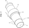
Fig. 1 is a perspective view illustrating an outer appearance of an image blur correction apparatus. -
Fig. 2 is a front view of a lens unit held by a unit holding part. -
Fig. 3 is a sectional schematic view of the unit holding part. -
Fig. 4 is a perspective view illustrating a configuration of a drive unit. -
Fig. 5 is a view for describing an operation of the drive unit. -
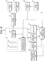
Fig. 6 is a view illustrating an example of a configuration of a first embodiment. -
Fig. 7 is a view illustrating an example of a configuration of a blur correction control unit. -
Fig. 8 is a view illustrating an example of a configuration of a servo arithmetic unit. -
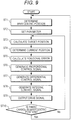
Fig. 9 is a flowchart illustrating an operation of the first embodiment. -
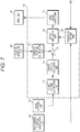
Fig. 10 is a view illustrating an example of a configuration of a second embodiment. -
Fig. 11 is a flowchart illustrating an operation of the second embodiment. - In the following, a mode for carrying out the present technique will be described. Note that the description will be made in the following order.
- 1. Configuration of image blur correction apparatus
- 2. First embodiment
- 2-1. Configuration of first embodiment
- 2-2. Operation of first embodiment
- 3. Second embodiment
- 3-1. Configuration and operation of second embodiment
- The image blur correction apparatus includes a lens unit, a shake detection unit, a barycentric position calculation unit, a position detection unit, a drive unit, and a blur correction control unit. The lens unit includes an imaging optical system and an imaging unit to generate an image signal of an imaged image and is supported rotatably in a yawing direction and in a pitching direction. The shake detection unit detects a shake applied to the lens unit. The barycentric position calculation unit calculates a barycentric position of the lens unit. The position detection unit detects a position of the lens unit. The drive unit performs rotation driving of the lens unit in the yawing direction and in the pitching direction. Also, based on the shake detected by the shake detection unit, the position of the lens unit which position is detected by the position detection unit, and the barycentric position of the lens unit, the blur correction control unit controls driving operation which is performed by the drive unit and corrects an image blur of the imaged image.
-
Fig. 1 is a perspective view illustrating an outer appearance of the image blur correction apparatus. In the image blur correction apparatus, alens unit 20 is held by anunit holding part 42 rotatably in a yawing direction and in a pitching direction. Also, the image blur correction apparatus rotates thelens unit 20 in the yawing direction and in the pitching direction based on a drive signal from the blur correction control unit and corrects an image blur of an imaged image which blur is caused due to a shake applied to thelens unit 20. Also, amirror tube 21 of thelens unit 20 is extended and contracted in an optical axis direction of the imaging lens according, for example, to a change of a zoom ratio. -
Fig. 2 is a front view of the lens unit held by the unit holding part andFig. 3 is a sectional schematic view of the unit holding part. Note thatFig. 3 illustrates a sectional surface in the optical axis direction of the lens unit (sectional view at position illustrated in A-A' line inFig. 1 ). - On the
mirror tube 21 of thelens unit 20, a protruded surface which is a part of a spherical surface with a predetermined position on the optical axis of the imaging lens as a center position CP is formed as a rollingsurface 22 in a zonal manner in a circumferential direction of a surface of themirror tube 21. In theunit holding part 42, on a surface which faces the rollingsurface 22 formed on themirror tube 21, aball holding part 43 is formed and aball 44 is held by theball holding part 43 in such a manner that theball 44 can roll on the rollingsurface 22. A plurality ofball holding parts 43 is formed in such a manner to sandwich a top part of the rollingsurface 22. For example, inFig. 3 , twoball holding parts 43 are formed in such a manner to sandwich the top part of the rollingsurface 22. Furthermore, the plurality ofball holding parts 43 is provided to theunit holding part 42 in a circumferential direction of themirror tube 21 in such a manner that a position of themirror tube 21 does not move in a radial direction. For example, as illustrated inFig. 2 , theball holding parts 43 are provided in such a manner that a distance therebetween becomes 120°. - Thus, while being held by the
unit holding part 42, thelens unit 20 becomes rotatable in the yawing direction and in the pitching direction with the center position CP of the rollingsurface 22 as reference. Note that theunit holding part 42 is formed, for example, in achassis 41 which will be described later. -
Fig. 4 is a perspective view illustrating a configuration of the drive unit to perform rotation driving of the lens unit in the yawing direction and in the pitching direction. Thedrive unit 45 is provided to a surface of a chassis which faces a rear end surface of thelens unit 20. Thedrive unit 45 includes drive coils 45ya and 45yb to rotate thelens unit 20 in the yawing direction and drive coils 45pa and 45pb to rotate thelens unit 20 in the pitching direction. Also, a magnet 25ya is provided to a position, which corresponds to that of the drive coil 45ya, on the rear end surface of thelens unit 20. Similarly, to positions respectively corresponding to those of the drive coils 45yb, 45pa, and 45pb, magnets 25yb, 25pa, and 25pb are respectively provided. - In the magnet 25ya, a magnet in which a magnetic pole of a surface facing the drive coil 45ya is a South pole and a magnet in which a magnetic pole of a surface facing the drive coil 45ya is a North pole are lined up in a horizontal direction. Note that in
Fig. 4 , the magnet in which a magnetic pole of the surface facing the drive coil is the South pole is highlighted. In the magnet 25yb, a magnet in which a magnetic pole of a surface facing the drive coil 45yb is the South pole and a magnet in which a magnetic pole of a surface facing the drive coil 45yb is the North pole are lined up in the horizontal direction. - In the magnet 25pa, a magnet in which a magnetic pole of a surface facing the drive coil 45pa is the South pole and a magnet in which a magnetic pole of a surface facing the drive coil 45pa is the North pole are lined up in a vertical direction. In the magnet 25pb, a magnet in which a magnetic pole of a surface facing the drive coil 45pb is the South pole and a magnet in which a surface facing the drive coil 45pb is the North pole are lined up in the vertical direction.
- With the
lens unit 20 as a center position (center position of rotation range), the magnet 25ya (25yb) and the drive coil 45ya (45yb) are arranged in such a manner that a center position between two magnets lined up in the horizontal direction in the magnet 25ya (25yb) becomes a center position of the drive coil 45ya (45yb). Similarly, with thelens unit 20 as the center position, the magnet 25pa (25pb) and the drive coil 45pa (45pb) are arranged in such a manner that a center position between two magnets lined up in the vertical direction in the magnet 25pa (25pb) becomes a center position of the drive coil 45pa (45pb). - Moreover, to an inner side of each of the drive coils 45ya (45yb) and 45pa (45pb), a
position detection unit 46 to determine a rotation position of thelens unit 20 by detecting a magnetic field generated by each of the magnets 25ya (25yb) and 25pa (25pb) is provided. For example, theposition detection units 46 are configured by respectively using hall elements 46ya (46yb) and 46pa (46pb). -
Fig. 5 is a view for describing an operation of the drive unit. Note that inFig. 5 , an example of a rotation operation in the pitching direction is illustrated. Also, thedrive unit 45 is provided to a surface of achassis 411 which surface faces a rear end surface of thelens unit 20. - As described above, since the
ball 44 is provided between the rollingsurface 22 and theball holding part 43 of theunit holding part 42, thelens unit 20 is held rotatably with the center position CP of the rollingsurface 22 as a fulcrum point of rotation. - Also, with the
lens unit 20 as the center position (center position of rotatable range), arrangement is performed in such a manner that a center position between two magnets lined up in the vertical direction in the magnet 25pa (25pb) becomes a center position of the drive coil 45pa (45pb). Here, when current is supplied to the drive coil 45pa (45pb), a magnetic field is generated according to the supplied current and the magnet 25pa (25pb) is moved in the vertical direction by the generated magnetic field. That is, by supplying current to the drive coil 45pa (45pb) and rotating thelens unit 20 according to a shake in the pitching direction applied to thelens unit 20, an image blur in the pitching direction can be corrected. Although not illustrated, by supplying current to the drive coil 45ya (45yb) and rotating thelens unit 20 according to a shake in the yawing direction applied to thelens unit 20, an image blur in the yawing direction can be corrected. - In such a manner, by rotating the
lens unit 20 by thedrive unit 45 according to a shake applied to thelens unit 20, an image blur can be corrected. - Note that a configuration to rotate the
lens unit 20 in the yawing direction and in the pitching direction is not limited to the configuration illustrated inFig. 1 to Fig. 5 . For example, a first rotary shaft is provided in the vertical direction (horizontal direction) of the lens unit and the first rotary shaft is held rotatably by an inner frame. Also, the first rotary shaft is rotated in the yawing direction (pitching direction) by a motor or the like. Moreover, a second rotary shaft is provided in the horizontal direction (vertical direction) of the inner frame and the second rotary shaft is held rotatably by an outer frame. Also, the second rotary shaft is rotated in the pitching direction (yawing direction) by a motor or the like. As described, thelens unit 20 may be supported rotatably by the first rotary shaft and the second rotary shaft and each of the first rotary shaft and the second rotary shaft may be rotated by a motor or the like. -
Fig. 6 is a view illustrating an example of a configuration of the first embodiment. Animaging apparatus 10 using the image blur correction apparatus includes thelens unit 20, thedrive unit 45, theposition detection unit 46, animage processing unit 51, adisplay unit 52, arecording unit 53, ashake detection unit 61, a barycentricposition calculation unit 62, a blurcorrection control unit 70, anuser interface unit 81, and acontrol unit 85. - To the
lens unit 20, an imagingoptical system 31, an imaging opticalsystem drive unit 32, and animaging unit 33 are provided. - The imaging
optical system 31 includes afocus lens 311, azoom lens 312, or the like. In the imagingoptical system 31, for example, thefocus lens 311 is moved in an optical axis direction and a focus adjustment is performed. Also, thezoom lens 312 is moved in the optical axis direction and a focal length is varied. - The imaging optical
system drive unit 32 drives thefocus lens 311 or thezoom lens 312 based on a control signal from thecontrol unit 85 which will be described later. - The
imaging unit 33 includes an imaging element, a preprocessing unit, an imaging drive unit, and the like. The imaging element performs photoelectric conversion processing and converts an optical image, which is formed on an imaging surface by the imagingoptical system 31, into an electric signal. As the imaging element, for example, a charge coupled device (CCD) image sensor or a complementary metal-oxide semiconductor (CMOS) image sensor is used. The preprocessing unit performs noise elimination processing such as correlated double sampling (CDS) on the electric signal generated in the imaging element. Also, the preprocessing unit performs a gain adjustment to make a signal level of the electric signal into an intended signal level. Furthermore, the preprocessing unit performs A/D conversion processing and converts an analog image signal, which is the electric signal on which the noise elimination processing or the gain adjustment is performed, into a digital image signal. Then, the preprocessing unit outputs the digital image signal to animage processing unit 51. The imaging drive unit generates an operation pulse or the like necessary for driving the imaging element based on a control signal from thecontrol unit 85 which will be described later. For example, an electric charge reading pulse to read electric charge, a transfer pulse to perform transfer in the vertical direction or the horizontal direction, and a shutter pulse to perform an electronic shutter operation are generated. - As described above, the
drive unit 45 rotates thelens unit 20 in the yawing direction and in the pitching direction based on a drive signal supplied from the blurcorrection control unit 70. Also, theposition detection unit 46 generates a detection signal corresponding to a position of thelens unit 20 and outputs the detection signal to the blurcorrection control unit 70. For example, detection signals respectively generated in the hall elements 46ya (46yb) and 46pa (46pb) are output to the blurcorrection control unit 70. - The
image processing unit 51 performs camera process processing or the like on the digital image signal output from theimaging unit 33. For example, on the image signal, theimage processing unit 51 performs nonlinear processing, color correction processing, contour emphasizing processing, or the like such as gamma correction or knee correction. Theimage processing unit 51 outputs the processed image signal to thedisplay unit 52 or therecording unit 53. - The
display unit 52 configures a display panel or an electronic viewfinder and performs, for example, display of a live view image based on the image signal output from theimage processing unit 51. Also, thedisplay unit 52 performs menu display, operation state display, or the like to perform operation setting of theimaging apparatus 10. Note that when the number of display pixels is less than the number of pixels of the imaged image, thedisplay unit 52 performs processing to convert the imaged image into a display image of the number of display images. - The
recording unit 53 records the image signal output from theimage processing unit 51 into a recording medium. The recording medium may be a removable medium such as a memory card, an optical disk, or a magnetic tape or may be a fixed-type hard disk drive (HDD), semiconductor memory module, or the like. Also, an encoder or a decoder may be provided to therecording unit 53 and compression coding or extension decoding of the image signal may be performed. To the recording medium, a coded signal may be recorded. Note that in therecording unit 53, an image signal or a coded signal recorded in the recording medium may be read and a recorded image may be displayed on thedisplay unit 52. - The
shake detection unit 61 includes a sensor to detect a shake applied to the imaging apparatus 10 (lens unit 20) such as an acceleration sensor or a gyro sensor. Theshake detection unit 61 detects a shake applied to the imaging apparatus 10 (lens unit 20) and outputs a result of the detection to the blurcorrection control unit 70. - The barycentric
position calculation unit 62 calculates a barycentric position of thelens unit 20 which position changes according to a position of thefocus lens 311 or thezoom lens 312 of the imagingoptical system 31 and an extension state of themirror tube 21. For example, a barycentric position is previously calculated for each position of thefocus lens 311 or thezoom lens 312 and each extension state of themirror tube 21 and is tabulated and stored into the barycentricposition calculation unit 62. The barycentricposition calculation unit 62 calculates the barycentric position of thelens unit 20 by acquiring, from thelens unit 20, information indicating a position of thefocus lens 311 or thezoom lens 312 and an extension state of themirror tube 21 and by selecting, from the table, a barycentric position corresponding to the acquired information. Also, based on a position of thefocus lens 311 or thezoom lens 312 of the imagingoptical system 31 and an extension state of themirror tube 21, the barycentricposition calculation unit 62 may calculate a barycentric position of thelens unit 20 by performing calculation at each time. Furthermore, the barycentricposition calculation unit 62 may calculate a barycentric position of thelens unit 20 by using a control signal supplied from thecontrol unit 85 to the imaging opticalsystem drive unit 32. For example, the barycentricposition calculation unit 62 determines a position of thefocus lens 311 or thezoom lens 312 and an extension state of themirror tube 21 based on the control signal supplied to the imaging opticalsystem drive unit 32 and calculates a barycentric position of thelens unit 20 based on a result of the determination. The barycentricposition calculation unit 62 outputs the barycentric position of thelens unit 20 to the blurcorrection control unit 70. - The blur
correction control unit 70 generates a drive signal based on the shake detected by theshake detection unit 61 and the position of thelens unit 20 detected by theposition detection unit 46. The blurcorrection control unit 70 supplies the generated drive signal to thedrive unit 45 and makes it possible to generate an image signal of an imaged image, an image blur of which is corrected, in theimaging unit 33. Also, the blurcorrection control unit 70 controls generation of a drive signal based on the barycentric position calculated by the barycentricposition calculation unit 62 and makes it possible to constantly generate the image signal of the imaged image, an image blur of which is corrected, in theimaging unit 33 even when the barycentric position of thelens unit 20 varies. - The user interface (user I/F)
unit 81 includes a zoom lever, a shooting button, and the like. The user I/F unit 81 generates an operation signal corresponding to user operation and outputs the operation signal to thecontrol unit 85. - The
control unit 85 includes, for example, a central processing unit (CPU), a read only memory (ROM), and a random access memory (RAM). The CPU reads and executes a program housed in the ROM when necessary. In the ROM, the program executed in the CPU, data which becomes necessary in various kinds of processing, and the like are stored in advance. The RAM is a memory which is used as a so-called work area which temporarily stores a halfway result of processing. Also, the ROM or the RAM stores various kinds of control information, correction data, and the like. Thecontrol unit 85 performs control of each unit according to an operation signal or the like from the user I/F unit 81 and makes theimaging apparatus 10 perform an operation corresponding to user operation. Also, thecontrol unit 85 controls the blurcorrection control unit 70 and makes the blurcorrection control unit 70 perform an image blur correction operation. -
Fig. 7 is a view illustrating an example of a configuration of the blur correction control unit. The blurcorrection control unit 70 includes a shakeamount calculation unit 71, a targetposition calculation unit 72, a currentposition calculation unit 73, anarithmetic unit 74, aparameter setting unit 75, aservo arithmetic unit 76, and a drivesignal output unit 77. - The shake
amount calculation unit 71 calculates a shake amount of the shake applied to the imaging apparatus 10 (lens unit 20) based on a detection signal supplied from theshake detection unit 61. The shakeamount calculation unit 71 outputs the calculated shake amount to the targetposition calculation unit 72. - Based on the shake amount calculated by the shake
amount calculation unit 71, the targetposition calculation unit 72 calculates a position of thelens unit 20 at which position an image signal of an imaged image, in which an image blur is not caused, can be generated in theimaging unit 33. Then, the targetposition calculation unit 72 outputs the calculated position as a target position to thearithmetic unit 74. - The current
position calculation unit 73 calculates a current position of thelens unit 20 based on a detection signal from theposition detection unit 46 such as detection signals respectively generated in the hall elements 46ya (46yb) and 46pa (46pb). The currentposition calculation unit 73 outputs the calculated current position from thearithmetic unit 74 to thearithmetic unit 74. - The
arithmetic unit 74 calculates an error between the target position and the current position and outputs a positional error signal indicating the calculated error amount to theservo arithmetic unit 76. - Based on a control signal from the
control unit 85, theparameter setting unit 75 performs setting of a parameter used in theservo arithmetic unit 76. Also, based on the barycentric position calculated by the barycentricposition calculation unit 62, theparameter setting unit 75 changes the parameter in such a manner that an image signal of an imaged image, an image blur of which is corrected, can be constantly generated in theimaging unit 33 even when the barycentric position of thelens unit 20 varies. - The
servo arithmetic unit 76 performs a servo operation by using the parameter set by theparameter setting unit 75 and generates a control signal in such a manner that the error amount calculated by thearithmetic unit 74 becomes "0". Then, theservo arithmetic unit 76 outputs the control signal to the drivesignal output unit 77. - By generating a drive signal based on the control signal supplied from the
servo arithmetic unit 76 and by supplying the drive signal to thedrive unit 45, the drivesignal output unit 77 drives thelens unit 20 with thedrive unit 45 in such a manner that thelens unit 20 is at the target position calculated by the targetposition calculation unit 72. - As described, by performing feedback control based on a result of the detection by the
shake detection unit 61 or the barycentric position and the current position of the lens unit, the blurcorrection control unit 70 makes it possible to generate an image signal of an imaged image, an image blur of which is corrected, in theimaging unit 33. - Next, a servo arithmetic unit will be described. For example, the
servo arithmetic unit 76 performs feedback processing by PID control in which proportional control (P control), integral control (I control unit), and differential control (D control) are selectively combined. In the PID control, the differential control (D control) is used to improve a decrease in a gain margin and a phase margin due to overcontrol by the proportional control (P control) and to improve stability of the feedback processing. The integral control (I control) is used to improve an offset property of the feedback processing. By selecting and combining the proportional control, the differential control, and the integral control as needed, the PID control is performed. In the proportional control, a calculation of an equation (1) is performed and a control output is calculated.
- In the differential control a calculation of an equation (2) is performed and a control output is calculated.

- In the integral control, a calculation of an equation (3) is performed and a control output is calculated.

-
Fig. 8 is a view illustrating an example of a configuration of the servo arithmetic unit. Theservo arithmetic unit 76 includesamplifier units delay units arithmetic units - The
amplifier unit 761 multiplies the positional error signal supplied from thearithmetic unit 74 by a proportional gain Kp set by theparameter setting unit 75 and generates a proportional control signal which is a proportional control output. Theamplifier unit 761 outputs the generated proportional control signal to thearithmetic unit 769. - The
delay unit 762 delays the positional error signal supplied from thearithmetic unit 74 for one sampling period and outputs the delayed signal to thearithmetic unit 763. - The
arithmetic unit 763 performs arithmetic processing to subtract the positional error signal, which is output from thedelay unit 762, from the positional error signal supplied from thearithmetic unit 74 and generates a differential signal of the positional error. Then, thearithmetic unit 763 outputs the differential signal to theamplifier unit 764. - The
amplifier unit 764 multiplies the differential signal supplied from thearithmetic unit 763 by a differential gain Kd set by theparameter setting unit 75 and generates a differential control signal which is a differential control output. Theamplifier unit 764 outputs the generated differential control signal to thearithmetic unit 769. - The
arithmetic unit 765 performs arithmetic processing to add a signal output from thedelay unit 766 to the positional error signal supplied from thearithmetic unit 74 and generates an integral signal of the positional error. Then, thearithmetic unit 765 outputs the integral signal to theamplifier unit 767. - The
delay unit 766 delays the integral signal supplied from thearithmetic unit 765 for one sampling period and outputs the delayed signal to thearithmetic unit 765. - The
amplifier unit 767 multiplies the integral signal supplied from thearithmetic unit 765 by an integral gain Ki set by theparameter setting unit 75 and generates an integral control signal which is an integral control output. Theamplifier unit 767 outputs the generated integral control signal to thearithmetic unit 768. - The
arithmetic unit 768 adds a gravity compensation signal, which is supplied from theparameter setting unit 75, to the integral control signal supplied from theamplifier unit 767 and outputs the signal to thearithmetic unit 769. Note that the gravity compensation signal is a signal to cancel a load due to the gravity and a detail thereof will be described later. - The
arithmetic unit 769 adds the proportional control signal supplied from theamplifier unit 761, the differential control signal supplied from theamplifier unit 764, and the integral control signal (to which gravity compensation signal is already added) supplied from thearithmetic unit 768 to each other and outputs a control signal after the adding to the drivesignal output unit 77. - Note that in the generation of the integral control signal, after a signal corresponding to a load due to the gravity is added to the integral signal supplied to the
amplifier unit 767, multiplying with the integral gain Ki may be performed by theamplifier unit 767 and a control signal equivalent to the integral control signal to which the gravity compensation signal is added may be generated. Also, a gain corresponding to a load due to the gravity (gravity compensation gain) may be added to the integral gain Ki and a control signal equivalent to the integral control signal to which the gravity compensation signal is added may be generated. Also, a control method is not limited to the PID control and a different control method may be used. -
Fig. 9 is a flowchart illustrating an operation of the first embodiment. In step ST1, the blurcorrection control unit 70 determines a barycentric position. The blurcorrection control unit 70 acquires a barycentric position of thelens unit 20 which position is calculated by the barycentricposition calculation unit 62 and performs determination of the barycentric position. Then, the blurcorrection control unit 70 goes to step ST2. - In step ST2, the blur
correction control unit 70 performs parameter setting. The blurcorrection control unit 70 sets a parameter based on a control signal from thecontrol unit 85. Also, the blurcorrection control unit 70 changes the parameter according to the barycentric position of thelens unit 20 and goes to step ST3. - In step ST3, the blur
correction control unit 70 calculates a target position. The blurcorrection control unit 70 calculates a shake amount of a shake applied to the imaging apparatus 10 (lens unit 20) based on a detection signal supplied from theshake detection unit 61. Based on the calculated shake amount, the blurcorrection control unit 70 calculates, as a target position, a position of thelens unit 20 at which position an image signal of an imaged image in which an image blur is not caused can be generated in theimaging unit 33, and goes to step ST4. - In step ST4, the blur
correction control unit 70 determines a current position. The blurcorrection control unit 70 acquires a detection signal from theposition detection unit 46, calculates a current position of thelens unit 20 based on the acquired detection signal, performs determination of the current position, and goes to step ST5. - In step ST5, the blur
correction control unit 70 calculates a positional error. The blurcorrection control unit 70 calculates an error between the target position and the current position, generates a positional error signal indicating the calculated error, and goes to step ST6. - In step ST6, the blur
correction control unit 70 generates a proportional control signal. The blurcorrection control unit 70 performs a calculation expressed by the above-described equation (1), generates a proportional control signal by multiplying the positional error signal by the proportional gain Kp, and goes to step ST7. - In step ST7, the blur
correction control unit 70 generates a differential control signal. The blurcorrection control unit 70 performs a calculation expressed by the above-described equation (2), generates a differential control signal by generating a differential signal from the positional error signal and by multiplying the differential signal by the differential gain Kd, and goes to step ST8. - In step ST8, the blur
correction control unit 70 generates an integral control signal. The blurcorrection control unit 70 performs a calculation expressed by the above-described equation (3) and generates an integral control signal by generating an integral signal from the positional error signal and by multiplying the integral signal by the integral gain Ki. Also, the blurcorrection control unit 70 adds a gravity compensation signal to the integral control signal and goes to step ST9. - In step ST9, the blur
correction control unit 70 outputs a drive signal. The blurcorrection control unit 70 adds the proportional control signal, the differential control signal, and the integral control signal to each other and generates a drive signal based on the control signal after the adding. The blurcorrection control unit 70 outputs the generated drive signal to thedrive unit 45 and goes to step ST10. - In step ST10, the blur
correction control unit 70 determines whether there is a change in the barycentric position. The blurcorrection control unit 70 determines whether an movement operation of the focus lens or the zoom lens or an extension/contraction operation of the mirror tube is performed and a change in the barycentric position is caused. When determining that there is a change in the barycentric position, the blurcorrection control unit 70 goes back to step ST1 and when determining that there is no change in the barycentric position, the blurcorrection control unit 70 goes back to step ST3. - Note that either of the processing in step ST3 and the processing in step ST4 may be performed first. Also, an order of the processing from step ST6 to step ST8 is not limited to the order illustrated in the drawing.
- Next, a parameter setting operation performed by the blur
correction control unit 70 will be described. Based on a control signal from thecontrol unit 85, theparameter setting unit 75 of the blurcorrection control unit 70 sets a proportional gain Kp, a differential gain Kd, and an integral gain Ki with which stable image blur correction can be performed, for example, in a case where a barycentric position is at a predetermined position. Theparameter setting unit 75 supplies the set parameter to theservo arithmetic unit 76. Also, when the barycentric position calculated by the barycentricposition calculation unit 62 is different from the predetermined position, such as in a case where the barycentric position is a position away from a support position where thelens unit 20 is supported rotatably, larger driving force becomes necessary to rotate thelens unit 20. That is, this case becomes similar to a case where inertia of thelens unit 20 is increased in thedrive unit 45. In such a case, based on the barycentric position, theparameter setting unit 75 increases the proportional gain Kp as the inertia is increased, and increases driving force of thelens unit 20. Moreover, theparameter setting unit 75 adjusts the differential gain Kd or the integral gain Ki in such a manner that good image blur correction can be performed even when the proportional gain Kp is increased. For example, the differential gain Kd is adjusted in such a manner that a good response can be acquired and feedback processing can be performed in a stable manner without generation of oscillation even when the proportional gain Kp is increased. Also, the integral gain Ki is adjusted in such a manner that an offset property of the feedback processing becomes good and thelens unit 20 is securely at a target position even when the proportional gain Kp is increased. - Moreover, as the barycentric position becomes further away from the support position of the
lens unit 20, a load (load in rotation direction) due to the gravity becomes large in thelens unit 20. Thus, in the servo operation, integral control is performed by using a correction value corresponding to the barycentric position of the lens unit. For example, as described above, an integral control signal to which a gravity compensation signal to cancel a load (load in rotation direction due to gravity) which changes according to the barycentric position of the lens unit is added is generated. Alternatively, a control signal equivalent to the integral control signal to which the gravity compensation signal is added is generated by multiplying an integral signal by the integral gain Ki after a signal corresponding to a load due to the gravity is added to the integral signal. Alternatively, a control signal equivalent to the integral control signal to which the gravity compensation signal is added is generated by adding, to the integral gain Ki, a gravity compensation gain corresponding to a load due to the gravity. When the integral control signal is generated in such a manner, an inclination of thelens unit 20 due to an influence of the gravity before thelens unit 20 reaches a target position can be prevented. Note that when the integrated value becomes stable, a servo operation is performed with weighting by the gravity being included. Thus, adding of the gravity compensation signal or the gravity compensation gain only needs to be performed in a predetermined period from the beginning of the control until the integrated value becomes stable. - In such a manner, according to the first embodiment, when a shake range in which shake correction can be performed is broadened by rotating the lens unit in the yawing direction and in the pitching direction, in the blur
correction control unit 70, a parameter of the servo operation is changed according to a movement of the barycentric position of thelens unit 20 caused due to performance of a movement operation of the focus lens or the zoom lens, an extension/contraction operation of the mirror tube, or the like. Thus, for example, even when the barycentric position of the lens unit varies due to the performance of a focus adjusting operation or a zooming operation by the imaging apparatus, it becomes possible to perform optimal image blur correction and to improve performance in image blur correction. Also, since the parameter of the servo operation is changed according to a movement of the barycentric position, driving force to rotate thelens unit 20 does not become large. Thus, power consumption can be prevented from becoming large and image blur correction can be performed efficiently. - Incidentally, variation in the barycentric position of the lens unit is not limited to the focus adjusting operation or the zooming operation. For example, in a case where an accessory such as a conversion lens is mounted to a tip of the lens unit, a barycenter of the lens unit moves to the front. Also, since the accessory is mounted, weight of the lens unit is increased. Thus, in the second embodiment, a case where a control operation in image blur correction is switched according to a mounting state of an accessory will be described.
-
Fig. 10 is a view illustrating an example of a configuration of the second embodiment. Animaging apparatus 11 using an image blur correction apparatus includes alens unit 20, adrive unit 45, aposition detection unit 46, animage processing unit 51, adisplay unit 52, arecording unit 53, ashake detection unit 61, an barycentricposition calculation unit 62, anaccessory detection unit 63, a blurcorrection control unit 70, an user interface (user I/F)unit 81, and acontrol unit 85. - To the
lens unit 20, an imagingoptical system 31, an imaging opticalsystem drive unit 32, and animaging unit 33 are provided. - The imaging
optical system 31 includes afocus lens 311, azoom lens 312, or the like. In the imagingoptical system 31, for example, thefocus lens 311 is moved in an optical axis direction and a focus adjustment is performed. Also, thezoom lens 312 is moved in the optical axis direction and a focal length is varied. - The imaging optical
system drive unit 32 drives thefocus lens 311 or thezoom lens 312 based on a control signal from thecontrol unit 85 which will be described later. - The
imaging unit 33 includes an imaging element, a preprocessing unit, an imaging drive unit, and the like. The imaging element performs photoelectric conversion processing and converts an optical image, which is formed on an imaging surface by the imagingoptical system 31, into an electric signal. As the imaging element, for example, a charge coupled device (CCD) image sensor or a complementary metal-oxide semiconductor (CMOS) image sensor is used. The preprocessing unit performs noise elimination processing such as correlated double sampling (CDS) on the electric signal generated in the imaging element. Also, the preprocessing unit performs a gain adjustment to make a signal level of the electric signal into an intended signal level. Furthermore, the preprocessing unit performs A/D conversion processing and converts an analog image signal, which is the electric signal on which the noise elimination processing or the gain adjustment is performed, into a digital image signal. Then, the preprocessing unit outputs the digital image signal to animage processing unit 51. The imaging drive unit generates an operation pulse or the like necessary for driving the imaging element based on a control signal from thecontrol unit 85 which will be described later. For example, an electric charge reading pulse to read electric charge, a transfer pulse to perform transfer in the vertical direction or the horizontal direction, and a shutter pulse to perform an electronic shutter operation are generated. - As described above, the
drive unit 45 rotates thelens unit 20 in the yawing direction and in the pitching direction based on a drive signal supplied from the blurcorrection control unit 70. Also, theposition detection unit 46 generates a detection signal corresponding to a position of thelens unit 20 and outputs the detection signal to the blurcorrection control unit 70. For example, detection signals respectively generated in the hall elements 46ya (46yb) and 46pa (46pb) are output to the blurcorrection control unit 70. - The
image processing unit 51 performs camera process processing or the like on the digital image signal output from theimaging unit 33. For example, on the image signal, theimage processing unit 51 performs nonlinear processing, color correction processing, contour emphasizing processing, or the like such as gamma correction or knee correction. Theimage processing unit 51 outputs the processed image signal to thedisplay unit 52 or therecording unit 53. - The
display unit 52 configures a display panel or an electronic viewfinder and performs, for example, display of a live view image based on the image signal output from theimage processing unit 51. Also, thedisplay unit 52 performs menu display, operation state display, or the like to perform operation setting of theimaging apparatus 11. Note that when the number of display pixels is less than the number of pixels of the imaged image, thedisplay unit 52 performs processing to convert the imaged image into a display image of the number of display images. - The
recording unit 53 records the image signal output from theimage processing unit 51 into a recording medium. The recording medium may be a removable medium such as a memory card, an optical disk, or a magnetic tape or may be a fixed-type hard disk drive (HDD), semiconductor memory module, or the like. Also, an encoder or a decoder may be provided to therecording unit 53 and compression coding or extension decoding of the image signal may be performed. To the recording medium, a coded signal may be recorded. Note that in therecording unit 53, an image signal or a coded signal recorded in the recording medium may be read and a recorded image may be displayed on thedisplay unit 52. - The
shake detection unit 61 includes a sensor to detect a shake applied to the imaging apparatus 11 (lens unit 20) such as an acceleration sensor or a gyro sensor. Theshake detection unit 61 detects a shake applied to the imaging apparatus 11 (lens unit 20) and outputs a result of the detection to the blurcorrection control unit 70. - The barycentric
position calculation unit 62 calculates a barycenter of thelens unit 20 which changes according to a position of thefocus lens 311 or thezoom lens 312 of the imagingoptical system 31 and an extension state of themirror tube 21. For example, a barycentric position is previously calculated for each position of thefocus lens 311 or thezoom lens 312 and each extension state of themirror tube 21 and is stored into the barycentricposition calculation unit 62. The barycentricposition calculation unit 62 calculates the barycenter of thelens unit 20 by acquiring, from thelens unit 20, information indicating a position of thefocus lens 311 or thezoom lens 312 and an extension state of themirror tube 21 and by selecting a barycentric position corresponding to the acquired information. Also, the barycentricposition calculation unit 62 may calculate the barycenter of thelens unit 20 by using a control signal supplied from thecontrol unit 85 to the imaging opticalsystem drive unit 32. For example, the barycentricposition calculation unit 62 determines a position of thefocus lens 311 or thezoom lens 312 and an extension state of themirror tube 21 based on the control signal supplied to the imaging opticalsystem drive unit 32 and calculates a barycentric position of thelens unit 20 based on a result of the determination. The barycentricposition calculation unit 62 outputs the barycentric position of thelens unit 20 to the blurcorrection control unit 70. - The
accessory detection unit 63 detects whether an accessory is mounted to thelens unit 20. Also, in a case where a plurality of kinds of accessories can be mounted, a kind of the mounted accessory is detected. For example, theaccessory detection unit 63 automatically detects whether an accessory such as a conversion lens is mounted to the tip of thelens unit 20. The mounting of an accessory may be detected by using an optical detection unit such as a switch or a photoreflector and information related to the accessory may be acquired by performing communication with the accessory during the detection of the mounting of the accessory. The accessory is, for example, a conversion lens such as a teleconverter or a wide converter, a filter, or a hood which is mounted to the lens unit. Theaccessory detection unit 63 outputs a result of the detection to the blurcorrection control unit 70. - The blur
correction control unit 70 generates a drive signal based on the shake detected by theshake detection unit 61 and the position of thelens unit 20 detected by theposition detection unit 46. The blurcorrection control unit 70 supplies the generated drive signal to thedrive unit 45 and makes it possible to generate an image signal of an imaged image, an image blur of which is corrected, in theimaging unit 33. Also, the blurcorrection control unit 70 controls generation of a drive signal based on the barycentric position calculated by the barycentricposition calculation unit 62 and makes it possible to constantly generate the image signal of the imaged image, an image blur of which is corrected, in theimaging unit 33 even when the barycentric position of thelens unit 20 varies. Furthermore, based on a result of the detection by theaccessory detection unit 63, the blurcorrection control unit 70 controls the generation of the drive signal and makes it possible to constantly generate an image signal of an imaged image, an image blur of which is corrected, in theimaging unit 33 even when the barycentric position of thelens unit 20 varies or even when weight thereof is increased. - The user I/
F unit 81 includes a zoom lever, a shooting button, and the like. The user I/F unit 81 generates an operation signal corresponding to user operation and outputs the operation signal to thecontrol unit 85. - The
control unit 85 includes, for example, a central processing unit (CPU), a read only memory (ROM), and a random access memory (RAM). The CPU reads and executes a program housed in the ROM when necessary. In the ROM, the program executed in the CPU, data which becomes necessary in various kinds of processing, and the like are stored in advance. The RAM is a memory which is used as a so-called work area which temporarily stores a halfway result of processing. Also, the ROM or the RAM stores various kinds of control information, correction data, and the like. Thecontrol unit 85 performs control of each unit according to an operation signal or the like from the user I/F unit 81 and makes theimaging apparatus 11 perform an operation corresponding to user operation. Also, thecontrol unit 85 controls the blurcorrection control unit 70 and makes the blurcorrection control unit 70 perform an image blur correction operation. -
Fig. 11 is a flowchart illustrating an operation of the second embodiment. In step ST21, the blurcorrection control unit 70 detects an accessory. Based on a result of the detection by theaccessory detection unit 63, the blurcorrection control unit 70 detects what kind of accessory is mounted to thelens unit 20 and goes to step ST22. - In step ST22, the blur
correction control unit 70 determines a barycentric position. The blurcorrection control unit 70 acquires a barycentric position of thelens unit 20 which position is calculated by the barycentricposition calculation unit 62, performs determination of the barycentric position, and goes to step ST23. - In step ST23, the blur
correction control unit 70 performs parameter setting. The blurcorrection control unit 70 sets a parameter based on a control signal from thecontrol unit 85. Also, the blurcorrection control unit 70 changes a parameter according to the barycentric position of thelens unit 20 and goes to step ST24. - In step ST24, the blur
correction control unit 70 calculates a target position. The blurcorrection control unit 70 calculates a shake amount of the shake applied to the imaging apparatus 11 (lens unit 20) based on a detection signal supplied from theshake detection unit 61. Based on the calculated shake amount, the blurcorrection control unit 70 calculates, as a target position, a position of thelens unit 20 at which position an image signal of an imaged image in which an image blur is not caused can be generated in theimaging unit 33, and goes to step ST25. - In step ST25, the blur
correction control unit 70 determines a current position. The blurcorrection control unit 70 acquires a detection signal from theposition detection unit 46, calculates a current position of thelens unit 20 based on the acquired detection signal, performs determination of the current position, and goes to step ST26. - In step ST26, the blur
correction control unit 70 calculates a positional error. The blurcorrection control unit 70 calculates an error between the target position and the current position, generates a positional error signal indicating the calculated error, and goes to step ST27. - In step ST27, the blur
correction control unit 70 generates a proportional control signal. The blurcorrection control unit 70 performs a calculation expressed by the above-described equation (1), generates a proportional control signal by multiplying the positional error signal by a proportional gain Kp, and goes to step ST28. - In step ST28, the blur
correction control unit 70 generates a differential control signal. The blurcorrection control unit 70 performs a calculation expressed by the above-described equation (2), generates a differential control signal by generating a differential signal from the positional error signal and by multiplying the differential signal by a differential gain Kd, and goes to step ST29. - In step ST29, the blur
correction control unit 70 generates an integral control signal. The blurcorrection control unit 70 performs a calculation expressed by the above-described equation (3) and generates an integral control signal by generating an integral signal from the positional error signal and by multiplying the integral signal by an integral gain Ki. Also, the blurcorrection control unit 70 adds a gravity compensation signal to the integral control signal and goes to step ST30. - In step ST30, the blur
correction control unit 70 outputs a drive signal. The blurcorrection control unit 70 adds the proportional control signal, the differential control signal, and the integral control signal to each other and generates a drive signal based on the control signal after the adding. The blurcorrection control unit 70 outputs the generated drive signal to thedrive unit 45 and goes to step ST31. - In step ST31, the blur
correction control unit 70 detects whether the accessory is changed. Based on a result of the detection by theaccessory detection unit 63, the blurcorrection control unit 70 determines whether a change of the accessory, that is, a change in attachment/detachment state of the accessory or a change into a different accessory is performed. When there is no change in the accessory, the blurcorrection control unit 70 goes to step ST32 and when there is a change in the accessory, the blurcorrection control unit 70 goes back to step ST21. - In step ST32, the blur
correction control unit 70 determines whether there is a change in the barycentric position. The blurcorrection control unit 70 determines whether an movement operation of the focus lens or the zoom lens or an extension/contraction operation of the mirror tube is performed and a change in the barycentric position is caused. When determining that there is a change in the barycentric position, the blurcorrection control unit 70 goes back to step ST22 and when determining that there is no change in the barycentric position, the blurcorrection control unit 70 goes back to step ST24. - Note that either of the processing in step ST24 and the processing in step ST25 can be performed first. Also, an order of the processing from step ST27 to step ST29 is not limited to the order illustrated in the drawing.
- In such a manner, according to the second embodiment, when a shake range in which shake correction can be performed is broadened by rotating the lens unit in the yawing direction and in the pitching direction, in the blur
correction control unit 70, a parameter of the servo operation is changed according to a movement of the barycentric position of thelens unit 20 caused due to performance of a movement operation of the focus lens or the zoom lens, an extension/contraction operation of the mirror tube, or the like. Moreover, a parameter of the servo operation is changed according to an attachment/detachment state of an accessory or according to a mounted accessory. Thus, even when a barycentric position of the lens unit varies due to the performance of a focus adjusting operation or a zooming operation by the imaging apparatus and even when an accessory is used, it becomes possible to perform optimal image blur correction and to improve performance in image blur correction. Also, since a parameter of the servo operation is changed according to a movement of the barycentric position, driving force to rotate thelens unit 20 does not become large. Thus, power consumption can be prevented from becoming large. Also, even when weight of the lens unit is increased due to mounting of an accessory, driving force to rotate thelens unit 20 does not become insufficient and image blur correction can be performed efficiently. - Also, a series of processing described in the description can be executed by hardware, software, or a composite configuration of the two. When the processing is executed by software, a program in which a processing sequence is recorded is installed into a memory in a computer embedded into special hardware and is executed. Also, it is possible to install the program into a general computer which can execute various kinds of processing and to execute the program.
- For example, the program can be previously recorded into a hard disk or a read only memory (ROM) which functions as a recording medium. Alternatively, the program may be temporarily or permanently housed (recorded) in a removable recording medium such as a flexible disk, a compact disc read only memory (CD-ROM), a magneto optical (MO) disk, a digital versatile disc (DVD), a magnetic disk, or a semiconductor memory card. Such a removable recording medium can be provided as a so-called package software.
- Also, other than being installed from the removable recording medium to a computer, the program may be transferred from a download site to a computer in a wireless or wired manner through a network such as a local area network (LAN) or the Internet. In the computer, the program transferred in such a manner can be received and installed into a built-in recording medium such as a hard disk.
- Also, the present technique is not limited to the above described embodiments of the technique. Each of the embodiments of the present technique discloses the present technique as an example. It is obvious that modification or substitution of the embodiments can be performed by those skilled in the art. The scope of the present invention is defined by the appended claims.
- In an image blur correction apparatus, a method of correcting an image blur, and an imaging apparatus of the present technique, a lens unit including an imaging optical system and an imaging unit configured to generate an image signal of an imaged image is supported rotatably in a yawing direction and in a pitching direction. Based on a shake applied to the lens unit, a position of the lens unit, and a barycentric position of the lens unit, a driving operation by a drive unit to perform rotation driving of the lens unit in the yawing direction and in the pitching direction is controlled and correction of an image blur of the imaged image is performed. Thus, even when a barycentric position of the lens unit varies due to a focus adjusting operation, a zooming operation, or the like, it becomes possible to perform optimal image blur correction and to improve performance in image blur correction.
- Thus, for example, the present technique is suitable for an electronic device in which a length of a lens mirror tube changes due to a focus adjusting operation, a zooming operation, or the like.
-
- 10, 11
- imaging apparatus
- 20
- lens unit
- 21
- mirror tube
- 22
- rolling surface
- 25pa, 25pb, 25ya, 25yb
- magnet
- 31
- imaging optical system
- 32
- imaging optical system drive unit
- 33
- imaging unit
- 41
- chassis
- 42
- unit holding part
- 43
- ball holding part
- 44
- ball
- 45
- drive unit
- 45pa, 45pb, 45ya, 45yb
- drive coil
- 46
- position detection unit
- 46pa, 46pb, 46ya, 46yb
- hall element
- 51
- image processing unit
- 52
- display unit
- 53
- recording unit
- 61
- shake detection unit
- 62
- barycentric position calculation unit
- 63
- accessory detection unit
- 70
- blur correction control unit
- 71
- shake amount calculation unit
- 72
- target position calculation unit
- 73
- current position calculation unit
- 74, 763, 765, 768, 769
- arithmetic unit
- 75
- parameter setting unit
- 76
- servo arithmetic unit
- 77
- drive signal output unit
- 81
- user interface (user I/F) unit
- 85
- control unit
- 311
- focus lens
- 312
- zoom lens
- 411
- surface of a chassis
- 761, 764, 767
- amplifier unit
- 762, 766
- delay unit
Claims (7)
- An image blur correction apparatus comprising:a lens unit (20) which includes an imaging optical system (31) and an imaging unit configured to generate an image signal of an imaged image and which is supported rotatably in a yawing direction and in a pitching direction;a shake detection unit (61) configured to detect a shake applied to the lens unit;a position detection unit (46) configured to detect a position of the lens unit;a drive unit (45) configured to perform rotation driving of the lens unit in the yawing direction and in the pitching direction;a blur correction control unit (70) configured to correct an image blur of the imaged image by controlling the driving operation, which is performed by the drive unit, based on the shake detected by the shake detection unit, the position detected by the position detection unit, and a barycentric position of the lens unit; anda barycentric position calculation unit (62) configured to calculate the barycentric position of the lens unit, wherein the barycentric position calculation unit (62) calcullates the barycentric position based on a lens position of the lens unit and an extension state of a mirror tube of the lens unit.
- The image blur correction apparatus according to claim 1, wherein according to a deviation between a target position of the lens unit (20) which position is calculated based on the shake detected by the shake detection unit (61) and the position of the lens unit which position is detected by the position detection unit (46) and according to the barycentric position of the lens unit (62), the blur correction control unit (70) performs a combination of proportional control, differential control, and integral control and controls the driving operation in such a manner that the position of the lens unit becomes identical to the target position.
- The image blur correction apparatus according to claim 2, wherein in the integral control, the integral control is performed by using a correction value corresponding to the barycentric position of the lens unit (20).
- The image blur correction apparatus according to claim 3, wherein the correction value is set in such a manner to cancel a load which changes depending on the barycentric position of the lens unit (20).
- The image blur correction apparatus according to claim 1, further comprising an accessory detection unit (63) configured to detect mounting of an accessory to the lens unit,
wherein the blur correction control unit (70) controls the driving operation, which is performed by the drive unit (45), by using a result of the detection by the accessory detection unit. - A method of correcting an image blur, comprising:detecting a shake applied to a lens unit which includes an imaging optical system and an imaging unit configured to generate an image signal of an imaged image and which is supported rotatebly in a yawing direction and in a pitching direction;detecting a position of the lens unit;performing rotation driving of the lens unit in the yawing direction and in the pitching direction; andcorrecting an image blur of the imaged image by controlling a rotation driving operation of the lens unit based on the detected shake, the detected position, and a barycentric position of the lens unit,wherein the barycentric position is calculated based on a lens position of the lens unit and an extension state of a mirror tube of the lens unit.
- An imaging apparatus comprising the image blur correction apparatus of claim 1 comprising:a control unit (85) configured to control an operation of the blur correction control unit.
Applications Claiming Priority (2)
| Application Number | Priority Date | Filing Date | Title |
|---|---|---|---|
| JP2012156774 | 2012-07-12 | ||
| PCT/JP2013/063519 WO2014010303A1 (en) | 2012-07-12 | 2013-05-15 | Image shake correction device and image shake correction method and image pickup device |
Publications (3)
| Publication Number | Publication Date |
|---|---|
| EP2874003A1 EP2874003A1 (en) | 2015-05-20 |
| EP2874003A4 EP2874003A4 (en) | 2016-03-23 |
| EP2874003B1 true EP2874003B1 (en) | 2017-12-20 |
Family
ID=49915778
Family Applications (1)
| Application Number | Title | Priority Date | Filing Date |
|---|---|---|---|
| EP13816683.0A Not-in-force EP2874003B1 (en) | 2012-07-12 | 2013-05-15 | Image shake correction device and image shake correction method and image pickup device |
Country Status (4)
| Country | Link |
|---|---|
| US (1) | US9225903B2 (en) |
| EP (1) | EP2874003B1 (en) |
| JP (1) | JP6444733B2 (en) |
| WO (1) | WO2014010303A1 (en) |
Families Citing this family (52)
| Publication number | Priority date | Publication date | Assignee | Title |
|---|---|---|---|---|
| CN116405747A (en) | 2012-11-28 | 2023-07-07 | 核心光电有限公司 | Multi-aperture imaging system and method for acquiring images through multi-aperture imaging system |
| KR101634516B1 (en) | 2013-06-13 | 2016-06-28 | 코어포토닉스 리미티드 | Dual aperture zoom digital camera |
| CN108519656A (en) | 2013-07-04 | 2018-09-11 | 核心光电有限公司 | Small-sized focal length lens external member |
| US9571731B2 (en) | 2013-08-01 | 2017-02-14 | Corephotonics Ltd. | Thin multi-aperture imaging system with auto-focus and methods for using same |
| US9392188B2 (en) | 2014-08-10 | 2016-07-12 | Corephotonics Ltd. | Zoom dual-aperture camera with folded lens |
| CN112327464A (en) | 2015-01-03 | 2021-02-05 | 核心光电有限公司 | Miniature telephoto lens module and camera using the same |
| KR102160867B1 (en) | 2015-04-02 | 2020-09-29 | 코어포토닉스 리미티드 | Dual voice coil motor structure in a dual-optical module camera |
| CN111061041B (en) | 2015-04-16 | 2021-02-26 | 核心光电有限公司 | Auto-focus and optical image stabilization in compact folded cameras |
| EP3722860B1 (en) | 2015-05-28 | 2023-04-19 | Corephotonics Ltd. | Bi-directional stiffness for optical image stabilization and auto-focus in a digital camera |
| EP3598737B1 (en) | 2015-08-13 | 2020-12-09 | Corephotonics Ltd. | Dual aperture zoom camera with video support and switching / non-switching dynamic control |
| KR102225727B1 (en) | 2015-09-06 | 2021-03-10 | 코어포토닉스 리미티드 | Auto focus and optical image stabilization with roll compensation in a compact folded camera |
| JP6598676B2 (en) * | 2015-12-25 | 2019-10-30 | Hoya株式会社 | Imaging device |
| US10578948B2 (en) | 2015-12-29 | 2020-03-03 | Corephotonics Ltd. | Dual-aperture zoom digital camera with automatic adjustable tele field of view |
| JP6818426B2 (en) * | 2016-04-20 | 2021-01-20 | キヤノン株式会社 | Image shake correction device and its control method, image pickup device, program |
| US10979641B2 (en) | 2016-05-16 | 2021-04-13 | Sony Corporation | Imaging device and image shake correcting method |
| JP2017211443A (en) * | 2016-05-24 | 2017-11-30 | 多摩川精機株式会社 | Space stabilizer |
| EP3292685B1 (en) | 2016-05-30 | 2019-06-05 | Corephotonics Ltd. | Rotational ball-guided voice coil motor |
| WO2017221106A1 (en) | 2016-06-19 | 2017-12-28 | Corephotonics Ltd. | Frame synchronization in a dual-aperture camera system |
| US10706518B2 (en) | 2016-07-07 | 2020-07-07 | Corephotonics Ltd. | Dual camera system with improved video smooth transition by image blending |
| EP4224233A1 (en) | 2016-07-07 | 2023-08-09 | Corephotonics Ltd. | Linear ball guided voice coil motor for folded optic |
| WO2018066775A2 (en) * | 2016-10-05 | 2018-04-12 | 자화전자 주식회사 | Reflectometer driving device for ois |
| JP6559366B2 (en) | 2016-10-13 | 2019-08-14 | 富士フイルム株式会社 | Blur correction apparatus, imaging apparatus, and blur correction method |
| WO2018122650A1 (en) | 2016-12-28 | 2018-07-05 | Corephotonics Ltd. | Folded camera structure with an extended light-folding-element scanning range |
| EP4145206A1 (en) | 2017-01-12 | 2023-03-08 | Corephotonics Ltd. | Compact folded camera |
| JP6898460B2 (en) | 2017-02-23 | 2021-07-07 | コアフォトニクス リミテッド | Flexible camera lens design |
| CN114137791A (en) | 2017-03-15 | 2022-03-04 | 核心光电有限公司 | Camera device and mobile device with panoramic scanning range |
| WO2018198258A1 (en) * | 2017-04-26 | 2018-11-01 | 株式会社ニコン | Lens barrel, camera body, camera system |
| WO2019048904A1 (en) | 2017-09-06 | 2019-03-14 | Corephotonics Ltd. | Combined stereoscopic and phase detection depth mapping in a dual aperture camera |
| US10951834B2 (en) | 2017-10-03 | 2021-03-16 | Corephotonics Ltd. | Synthetically enlarged camera aperture |
| CN113075838B (en) | 2017-11-23 | 2022-11-29 | 核心光电有限公司 | Camera, manufacturing method thereof, mobile electronic equipment and method for reducing space occupied by bulges |
| KR102091369B1 (en) | 2018-02-05 | 2020-05-18 | 코어포토닉스 리미티드 | Reduced height penalty for folded cameras |
| KR102494003B1 (en) | 2018-02-12 | 2023-01-30 | 코어포토닉스 리미티드 | Folded camera with optical image stabilization |
| US10694168B2 (en) | 2018-04-22 | 2020-06-23 | Corephotonics Ltd. | System and method for mitigating or preventing eye damage from structured light IR/NIR projector systems |
| EP4303653A1 (en) | 2018-04-23 | 2024-01-10 | Corephotonics Ltd. | An optical-path folding-element with an extended two degree of freedom rotation range |
| WO2020031005A1 (en) | 2018-08-04 | 2020-02-13 | Corephotonics Ltd. | Switchable continuous display information system above camera |
| WO2020039302A1 (en) | 2018-08-22 | 2020-02-27 | Corephotonics Ltd. | Two-state zoom folded camera |
| WO2020144528A1 (en) | 2019-01-07 | 2020-07-16 | Corephotonics Ltd. | Rotation mechanism with sliding joint |
| CN111971956B (en) | 2019-03-09 | 2021-12-03 | 核心光电有限公司 | Method and system for dynamic stereo calibration |
| WO2020226000A1 (en) * | 2019-05-08 | 2020-11-12 | ソニー株式会社 | Signal processing device, signal processing method, program, and video display device |
| KR20240027858A (en) | 2019-07-31 | 2024-03-04 | 코어포토닉스 리미티드 | System and method for creating background blur in camera panning or motion |
| US11659135B2 (en) | 2019-10-30 | 2023-05-23 | Corephotonics Ltd. | Slow or fast motion video using depth information |
| US11949976B2 (en) | 2019-12-09 | 2024-04-02 | Corephotonics Ltd. | Systems and methods for obtaining a smart panoramic image |
| EP4049444A4 (en) | 2019-12-09 | 2022-11-16 | Corephotonics Ltd. | Systems and methods for obtaining a smart panoramic image |
| US11693064B2 (en) | 2020-04-26 | 2023-07-04 | Corephotonics Ltd. | Temperature control for Hall bar sensor correction |
| US11832018B2 (en) | 2020-05-17 | 2023-11-28 | Corephotonics Ltd. | Image stitching in the presence of a full field of view reference image |
| EP4191332A1 (en) | 2020-05-30 | 2023-06-07 | Corephotonics Ltd. | Systems and methods for obtaining a super macro image |
| JP7481918B2 (en) | 2020-06-22 | 2024-05-13 | ニデックインスツルメンツ株式会社 | Optical unit with shake correction function |
| US11637977B2 (en) | 2020-07-15 | 2023-04-25 | Corephotonics Ltd. | Image sensors and sensing methods to obtain time-of-flight and phase detection information |
| CN116125660A (en) | 2020-07-15 | 2023-05-16 | 核心光电有限公司 | Method for correcting viewpoint aberration of scan folding camera |
| EP4065934A4 (en) | 2020-07-31 | 2023-07-26 | Corephotonics Ltd. | Hall sensor-magnet geometry for large stroke linear position sensing |
| CN116679419A (en) | 2020-08-12 | 2023-09-01 | 核心光电有限公司 | Apparatus and method for optical anti-shake |
| UA125742C2 (en) * | 2021-08-27 | 2022-05-25 | Сергій Олександрович Тартишніков | Systems for stabilizing and controlling a movie camera |
Family Cites Families (15)
| Publication number | Priority date | Publication date | Assignee | Title |
|---|---|---|---|---|
| US5850575A (en) * | 1935-09-14 | 1998-12-15 | Nikon Corporation | Image vibration reduction device |
| JPH0636573B2 (en) * | 1985-07-05 | 1994-05-11 | 松下電器産業株式会社 | Imaging device |
| EP0417975B1 (en) * | 1989-09-10 | 1997-04-02 | Canon Kabushiki Kaisha | Automatic focusing system |
| EP0843201A1 (en) * | 1992-07-15 | 1998-05-20 | Nikon Corporation | Image-shake correcting photographic apparatus |
| JPH07274056A (en) | 1994-03-25 | 1995-10-20 | Sony Corp | Hand shake correction device for camera |
| JPH07319000A (en) * | 1994-05-27 | 1995-12-08 | Olympus Optical Co Ltd | Camera |
| US5696999A (en) * | 1995-09-12 | 1997-12-09 | Nikon Corporation | Image vibration reduction device |
| US6362852B2 (en) * | 1996-01-11 | 2002-03-26 | Sony Corporation | Focus control apparatus and method for use with a video camera or the like |
| JPH11142903A (en) * | 1997-11-13 | 1999-05-28 | Olympus Optical Co Ltd | Hand shake preventing device for optical device |
| JP3531642B2 (en) * | 2002-04-25 | 2004-05-31 | 株式会社ニコン | Interchangeable lens with image stabilization function |
| JP4661181B2 (en) * | 2004-11-19 | 2011-03-30 | コニカミノルタオプト株式会社 | Stepping motor servo drive method, drive mechanism, and imaging apparatus |
| JP4135729B2 (en) * | 2005-06-15 | 2008-08-20 | コニカミノルタオプト株式会社 | Lens barrel unit and imaging device equipped with the same |
| JP5063029B2 (en) * | 2006-04-28 | 2012-10-31 | 株式会社Jvcケンウッド | Lens drive device |
| JP5441679B2 (en) * | 2009-12-28 | 2014-03-12 | キヤノン株式会社 | Imaging device |
| JP5234132B2 (en) * | 2011-03-30 | 2013-07-10 | 株式会社Jvcケンウッド | Imaging device |
-
2013
- 2013-05-15 JP JP2014524680A patent/JP6444733B2/en not_active Expired - Fee Related
- 2013-05-15 WO PCT/JP2013/063519 patent/WO2014010303A1/en active Application Filing
- 2013-05-15 US US14/412,884 patent/US9225903B2/en active Active
- 2013-05-15 EP EP13816683.0A patent/EP2874003B1/en not_active Not-in-force
Non-Patent Citations (1)
| Title |
|---|
| None * |
Also Published As
| Publication number | Publication date |
|---|---|
| US9225903B2 (en) | 2015-12-29 |
| WO2014010303A1 (en) | 2014-01-16 |
| US20150195458A1 (en) | 2015-07-09 |
| EP2874003A1 (en) | 2015-05-20 |
| JPWO2014010303A1 (en) | 2016-06-20 |
| EP2874003A4 (en) | 2016-03-23 |
| JP6444733B2 (en) | 2018-12-26 |
Similar Documents
| Publication | Publication Date | Title |
|---|---|---|
| EP2874003B1 (en) | Image shake correction device and image shake correction method and image pickup device | |
| US9185298B2 (en) | Image blur correction apparatus, image blur correction method, and imaging apparatus | |
| JP5011387B2 (en) | Imaging device | |
| US20060257129A1 (en) | Image sensing apparatus equipped with anti-shake mechanism | |
| US7208905B2 (en) | Driving method, driving mechanism, and image capturing apparatus | |
| CN109951631B (en) | System and method for image stabilization for image capture | |
| WO2013145793A1 (en) | Movable member control device and imaging device provided with same | |
| JP2006184679A (en) | Imaging apparatus, camera shake compensation system, portable telephone and hand shake compensation method | |
| EP3460568B1 (en) | Imaging device and image blur correction method | |
| JP2009037069A (en) | Image blur correction device and imaging apparatus | |
| WO2012002149A1 (en) | Image processing method and apparatus | |
| US9398220B2 (en) | Shake correction apparatus and image pickup apparatus thereof, and optical device mountable on image pickup apparatus | |
| JP2009047757A (en) | Photographic device | |
| JP2014126657A (en) | Image jitter correction device, image jitter correction method and imaging device | |
| JP6395401B2 (en) | Image shake correction apparatus, control method therefor, optical apparatus, and imaging apparatus | |
| JP2010014814A (en) | Diaphragm device and imaging apparatus | |
| JP2020020878A (en) | Moving vehicle, focus control method, program, and recording medium | |
| JP6584259B2 (en) | Image blur correction apparatus, imaging apparatus, and control method | |
| JP7346076B2 (en) | Control device, lens device, imaging device, control method, and program | |
| JP6865720B2 (en) | Mobile objects, imaging control methods, programs, and recording media | |
| WO2023206087A1 (en) | Image stabilization apparatus, imaging apparatus, and image stabilization method | |
| WO2021200191A1 (en) | Image processing device and method, and program | |
| JP2011197093A (en) | Optical apparatus and interchangeable lens | |
| JP2017175599A (en) | Imaging apparatus | |
| JP2016191762A (en) | Camera system, interchangeable lens and camera |
Legal Events
| Date | Code | Title | Description |
|---|---|---|---|
| PUAI | Public reference made under article 153(3) epc to a published international application that has entered the european phase |
Free format text: ORIGINAL CODE: 0009012 |
|
| 17P | Request for examination filed |
Effective date: 20141222 |
|
| AK | Designated contracting states |
Kind code of ref document: A1 Designated state(s): AL AT BE BG CH CY CZ DE DK EE ES FI FR GB GR HR HU IE IS IT LI LT LU LV MC MK MT NL NO PL PT RO RS SE SI SK SM TR |
|
| AX | Request for extension of the european patent |
Extension state: BA ME |
|
| DAX | Request for extension of the european patent (deleted) | ||
| RA4 | Supplementary search report drawn up and despatched (corrected) |
Effective date: 20160223 |
|
| RIC1 | Information provided on ipc code assigned before grant |
Ipc: H04N 5/232 20060101ALI20160217BHEP Ipc: G03B 5/00 20060101AFI20160217BHEP |
|
| REG | Reference to a national code |
Ref country code: DE Ref legal event code: R079 Ref document number: 602013031167 Country of ref document: DE Free format text: PREVIOUS MAIN CLASS: G03B0005000000 Ipc: G02B0027640000 |
|
| RIC1 | Information provided on ipc code assigned before grant |
Ipc: G03B 5/00 20060101ALI20170706BHEP Ipc: G02B 27/64 20060101AFI20170706BHEP Ipc: H04N 5/232 20060101ALI20170706BHEP |
|
| GRAP | Despatch of communication of intention to grant a patent |
Free format text: ORIGINAL CODE: EPIDOSNIGR1 |
|
| INTG | Intention to grant announced |
Effective date: 20170817 |
|
| GRAS | Grant fee paid |
Free format text: ORIGINAL CODE: EPIDOSNIGR3 |
|
| GRAA | (expected) grant |
Free format text: ORIGINAL CODE: 0009210 |
|
| AK | Designated contracting states |
Kind code of ref document: B1 Designated state(s): AL AT BE BG CH CY CZ DE DK EE ES FI FR GB GR HR HU IE IS IT LI LT LU LV MC MK MT NL NO PL PT RO RS SE SI SK SM TR |
|
| REG | Reference to a national code |
Ref country code: GB Ref legal event code: FG4D |
|
| REG | Reference to a national code |
Ref country code: CH Ref legal event code: EP |
|
| REG | Reference to a national code |
Ref country code: IE Ref legal event code: FG4D |
|
| REG | Reference to a national code |
Ref country code: AT Ref legal event code: REF Ref document number: 956878 Country of ref document: AT Kind code of ref document: T Effective date: 20180115 |
|
| REG | Reference to a national code |
Ref country code: DE Ref legal event code: R096 Ref document number: 602013031167 Country of ref document: DE |
|
| REG | Reference to a national code |
Ref country code: NL Ref legal event code: MP Effective date: 20171220 |
|
| PG25 | Lapsed in a contracting state [announced via postgrant information from national office to epo] |
Ref country code: NO Free format text: LAPSE BECAUSE OF FAILURE TO SUBMIT A TRANSLATION OF THE DESCRIPTION OR TO PAY THE FEE WITHIN THE PRESCRIBED TIME-LIMIT Effective date: 20180320 Ref country code: SE Free format text: LAPSE BECAUSE OF FAILURE TO SUBMIT A TRANSLATION OF THE DESCRIPTION OR TO PAY THE FEE WITHIN THE PRESCRIBED TIME-LIMIT Effective date: 20171220 Ref country code: FI Free format text: LAPSE BECAUSE OF FAILURE TO SUBMIT A TRANSLATION OF THE DESCRIPTION OR TO PAY THE FEE WITHIN THE PRESCRIBED TIME-LIMIT Effective date: 20171220 Ref country code: LT Free format text: LAPSE BECAUSE OF FAILURE TO SUBMIT A TRANSLATION OF THE DESCRIPTION OR TO PAY THE FEE WITHIN THE PRESCRIBED TIME-LIMIT Effective date: 20171220 |
|
| REG | Reference to a national code |
Ref country code: LT Ref legal event code: MG4D |
|
| REG | Reference to a national code |
Ref country code: AT Ref legal event code: MK05 Ref document number: 956878 Country of ref document: AT Kind code of ref document: T Effective date: 20171220 |
|
| PG25 | Lapsed in a contracting state [announced via postgrant information from national office to epo] |
Ref country code: HR Free format text: LAPSE BECAUSE OF FAILURE TO SUBMIT A TRANSLATION OF THE DESCRIPTION OR TO PAY THE FEE WITHIN THE PRESCRIBED TIME-LIMIT Effective date: 20171220 Ref country code: LV Free format text: LAPSE BECAUSE OF FAILURE TO SUBMIT A TRANSLATION OF THE DESCRIPTION OR TO PAY THE FEE WITHIN THE PRESCRIBED TIME-LIMIT Effective date: 20171220 Ref country code: GR Free format text: LAPSE BECAUSE OF FAILURE TO SUBMIT A TRANSLATION OF THE DESCRIPTION OR TO PAY THE FEE WITHIN THE PRESCRIBED TIME-LIMIT Effective date: 20180321 Ref country code: BG Free format text: LAPSE BECAUSE OF FAILURE TO SUBMIT A TRANSLATION OF THE DESCRIPTION OR TO PAY THE FEE WITHIN THE PRESCRIBED TIME-LIMIT Effective date: 20180320 Ref country code: RS Free format text: LAPSE BECAUSE OF FAILURE TO SUBMIT A TRANSLATION OF THE DESCRIPTION OR TO PAY THE FEE WITHIN THE PRESCRIBED TIME-LIMIT Effective date: 20171220 |
|
| PG25 | Lapsed in a contracting state [announced via postgrant information from national office to epo] |
Ref country code: NL Free format text: LAPSE BECAUSE OF FAILURE TO SUBMIT A TRANSLATION OF THE DESCRIPTION OR TO PAY THE FEE WITHIN THE PRESCRIBED TIME-LIMIT Effective date: 20171220 |
|
| PG25 | Lapsed in a contracting state [announced via postgrant information from national office to epo] |
Ref country code: SK Free format text: LAPSE BECAUSE OF FAILURE TO SUBMIT A TRANSLATION OF THE DESCRIPTION OR TO PAY THE FEE WITHIN THE PRESCRIBED TIME-LIMIT Effective date: 20171220 Ref country code: CZ Free format text: LAPSE BECAUSE OF FAILURE TO SUBMIT A TRANSLATION OF THE DESCRIPTION OR TO PAY THE FEE WITHIN THE PRESCRIBED TIME-LIMIT Effective date: 20171220 Ref country code: CY Free format text: LAPSE BECAUSE OF FAILURE TO SUBMIT A TRANSLATION OF THE DESCRIPTION OR TO PAY THE FEE WITHIN THE PRESCRIBED TIME-LIMIT Effective date: 20171220 Ref country code: EE Free format text: LAPSE BECAUSE OF FAILURE TO SUBMIT A TRANSLATION OF THE DESCRIPTION OR TO PAY THE FEE WITHIN THE PRESCRIBED TIME-LIMIT Effective date: 20171220 Ref country code: ES Free format text: LAPSE BECAUSE OF FAILURE TO SUBMIT A TRANSLATION OF THE DESCRIPTION OR TO PAY THE FEE WITHIN THE PRESCRIBED TIME-LIMIT Effective date: 20171220 |
|
| PG25 | Lapsed in a contracting state [announced via postgrant information from national office to epo] |
Ref country code: IS Free format text: LAPSE BECAUSE OF FAILURE TO SUBMIT A TRANSLATION OF THE DESCRIPTION OR TO PAY THE FEE WITHIN THE PRESCRIBED TIME-LIMIT Effective date: 20180420 Ref country code: RO Free format text: LAPSE BECAUSE OF FAILURE TO SUBMIT A TRANSLATION OF THE DESCRIPTION OR TO PAY THE FEE WITHIN THE PRESCRIBED TIME-LIMIT Effective date: 20171220 Ref country code: SM Free format text: LAPSE BECAUSE OF FAILURE TO SUBMIT A TRANSLATION OF THE DESCRIPTION OR TO PAY THE FEE WITHIN THE PRESCRIBED TIME-LIMIT Effective date: 20171220 Ref country code: IT Free format text: LAPSE BECAUSE OF FAILURE TO SUBMIT A TRANSLATION OF THE DESCRIPTION OR TO PAY THE FEE WITHIN THE PRESCRIBED TIME-LIMIT Effective date: 20171220 Ref country code: AT Free format text: LAPSE BECAUSE OF FAILURE TO SUBMIT A TRANSLATION OF THE DESCRIPTION OR TO PAY THE FEE WITHIN THE PRESCRIBED TIME-LIMIT Effective date: 20171220 Ref country code: PL Free format text: LAPSE BECAUSE OF FAILURE TO SUBMIT A TRANSLATION OF THE DESCRIPTION OR TO PAY THE FEE WITHIN THE PRESCRIBED TIME-LIMIT Effective date: 20171220 |
|
| REG | Reference to a national code |
Ref country code: DE Ref legal event code: R097 Ref document number: 602013031167 Country of ref document: DE |
|
| PLBE | No opposition filed within time limit |
Free format text: ORIGINAL CODE: 0009261 |
|
| STAA | Information on the status of an ep patent application or granted ep patent |
Free format text: STATUS: NO OPPOSITION FILED WITHIN TIME LIMIT |
|
| 26N | No opposition filed |
Effective date: 20180921 |
|
| PG25 | Lapsed in a contracting state [announced via postgrant information from national office to epo] |
Ref country code: DK Free format text: LAPSE BECAUSE OF FAILURE TO SUBMIT A TRANSLATION OF THE DESCRIPTION OR TO PAY THE FEE WITHIN THE PRESCRIBED TIME-LIMIT Effective date: 20171220 |
|
| REG | Reference to a national code |
Ref country code: CH Ref legal event code: PL |
|
| GBPC | Gb: european patent ceased through non-payment of renewal fee |
Effective date: 20180515 |
|
| REG | Reference to a national code |
Ref country code: BE Ref legal event code: MM Effective date: 20180531 |
|
| PG25 | Lapsed in a contracting state [announced via postgrant information from national office to epo] |
Ref country code: MC Free format text: LAPSE BECAUSE OF FAILURE TO SUBMIT A TRANSLATION OF THE DESCRIPTION OR TO PAY THE FEE WITHIN THE PRESCRIBED TIME-LIMIT Effective date: 20171220 |
|
| REG | Reference to a national code |
Ref country code: IE Ref legal event code: MM4A |
|
| PG25 | Lapsed in a contracting state [announced via postgrant information from national office to epo] |
Ref country code: SI Free format text: LAPSE BECAUSE OF FAILURE TO SUBMIT A TRANSLATION OF THE DESCRIPTION OR TO PAY THE FEE WITHIN THE PRESCRIBED TIME-LIMIT Effective date: 20171220 Ref country code: LI Free format text: LAPSE BECAUSE OF NON-PAYMENT OF DUE FEES Effective date: 20180531 Ref country code: CH Free format text: LAPSE BECAUSE OF NON-PAYMENT OF DUE FEES Effective date: 20180531 |
|
| PG25 | Lapsed in a contracting state [announced via postgrant information from national office to epo] |
Ref country code: LU Free format text: LAPSE BECAUSE OF NON-PAYMENT OF DUE FEES Effective date: 20180515 |
|
| PG25 | Lapsed in a contracting state [announced via postgrant information from national office to epo] |
Ref country code: FR Free format text: LAPSE BECAUSE OF NON-PAYMENT OF DUE FEES Effective date: 20180531 Ref country code: IE Free format text: LAPSE BECAUSE OF NON-PAYMENT OF DUE FEES Effective date: 20180515 Ref country code: GB Free format text: LAPSE BECAUSE OF NON-PAYMENT OF DUE FEES Effective date: 20180515 |
|
| PG25 | Lapsed in a contracting state [announced via postgrant information from national office to epo] |
Ref country code: BE Free format text: LAPSE BECAUSE OF NON-PAYMENT OF DUE FEES Effective date: 20180531 |
|
| PG25 | Lapsed in a contracting state [announced via postgrant information from national office to epo] |
Ref country code: MT Free format text: LAPSE BECAUSE OF NON-PAYMENT OF DUE FEES Effective date: 20180515 |
|
| PG25 | Lapsed in a contracting state [announced via postgrant information from national office to epo] |
Ref country code: TR Free format text: LAPSE BECAUSE OF FAILURE TO SUBMIT A TRANSLATION OF THE DESCRIPTION OR TO PAY THE FEE WITHIN THE PRESCRIBED TIME-LIMIT Effective date: 20171220 |
|
| PG25 | Lapsed in a contracting state [announced via postgrant information from national office to epo] |
Ref country code: PT Free format text: LAPSE BECAUSE OF FAILURE TO SUBMIT A TRANSLATION OF THE DESCRIPTION OR TO PAY THE FEE WITHIN THE PRESCRIBED TIME-LIMIT Effective date: 20171220 |
|
| PG25 | Lapsed in a contracting state [announced via postgrant information from national office to epo] |
Ref country code: HU Free format text: LAPSE BECAUSE OF FAILURE TO SUBMIT A TRANSLATION OF THE DESCRIPTION OR TO PAY THE FEE WITHIN THE PRESCRIBED TIME-LIMIT; INVALID AB INITIO Effective date: 20130515 Ref country code: MK Free format text: LAPSE BECAUSE OF NON-PAYMENT OF DUE FEES Effective date: 20171220 |
|
| PG25 | Lapsed in a contracting state [announced via postgrant information from national office to epo] |
Ref country code: AL Free format text: LAPSE BECAUSE OF FAILURE TO SUBMIT A TRANSLATION OF THE DESCRIPTION OR TO PAY THE FEE WITHIN THE PRESCRIBED TIME-LIMIT Effective date: 20171220 |
|
| PGFP | Annual fee paid to national office [announced via postgrant information from national office to epo] |
Ref country code: DE Payment date: 20210421 Year of fee payment: 9 |
|
| REG | Reference to a national code |
Ref country code: DE Ref legal event code: R119 Ref document number: 602013031167 Country of ref document: DE |
|
| PG25 | Lapsed in a contracting state [announced via postgrant information from national office to epo] |
Ref country code: DE Free format text: LAPSE BECAUSE OF NON-PAYMENT OF DUE FEES Effective date: 20221201 |