EP2872022B1 - Frame for mop covers - Google Patents
Frame for mop covers Download PDFInfo
- Publication number
- EP2872022B1 EP2872022B1 EP12737269.6A EP12737269A EP2872022B1 EP 2872022 B1 EP2872022 B1 EP 2872022B1 EP 12737269 A EP12737269 A EP 12737269A EP 2872022 B1 EP2872022 B1 EP 2872022B1
- Authority
- EP
- European Patent Office
- Prior art keywords
- folding
- folding wings
- holder
- stop
- contact portion
- Prior art date
- Legal status (The legal status is an assumption and is not a legal conclusion. Google has not performed a legal analysis and makes no representation as to the accuracy of the status listed.)
- Active
Links
- 238000004140 cleaning Methods 0.000 claims description 9
- 230000008901 benefit Effects 0.000 description 4
- 230000002035 prolonged effect Effects 0.000 description 3
- 230000009471 action Effects 0.000 description 2
- 230000000694 effects Effects 0.000 description 2
- 230000005484 gravity Effects 0.000 description 2
- 238000003780 insertion Methods 0.000 description 2
- 230000037431 insertion Effects 0.000 description 2
- 238000003825 pressing Methods 0.000 description 2
- 239000012459 cleaning agent Substances 0.000 description 1
- 230000008878 coupling Effects 0.000 description 1
- 238000010168 coupling process Methods 0.000 description 1
- 238000005859 coupling reaction Methods 0.000 description 1
- 230000001419 dependent effect Effects 0.000 description 1
- 239000003599 detergent Substances 0.000 description 1
- 230000003670 easy-to-clean Effects 0.000 description 1
- 230000003993 interaction Effects 0.000 description 1
- 238000004519 manufacturing process Methods 0.000 description 1
- 230000007246 mechanism Effects 0.000 description 1
- 238000000034 method Methods 0.000 description 1
- 210000003205 muscle Anatomy 0.000 description 1
- 230000007480 spreading Effects 0.000 description 1
- 238000003892 spreading Methods 0.000 description 1
- XLYOFNOQVPJJNP-UHFFFAOYSA-N water Substances O XLYOFNOQVPJJNP-UHFFFAOYSA-N 0.000 description 1
Images


Classifications
-
- A—HUMAN NECESSITIES
- A47—FURNITURE; DOMESTIC ARTICLES OR APPLIANCES; COFFEE MILLS; SPICE MILLS; SUCTION CLEANERS IN GENERAL
- A47L—DOMESTIC WASHING OR CLEANING; SUCTION CLEANERS IN GENERAL
- A47L13/00—Implements for cleaning floors, carpets, furniture, walls, or wall coverings
- A47L13/10—Scrubbing; Scouring; Cleaning; Polishing
- A47L13/20—Mops
- A47L13/24—Frames for mops; Mop heads
- A47L13/254—Plate frames
- A47L13/258—Plate frames of adjustable or foldable type
-
- A—HUMAN NECESSITIES
- A47—FURNITURE; DOMESTIC ARTICLES OR APPLIANCES; COFFEE MILLS; SPICE MILLS; SUCTION CLEANERS IN GENERAL
- A47L—DOMESTIC WASHING OR CLEANING; SUCTION CLEANERS IN GENERAL
- A47L13/00—Implements for cleaning floors, carpets, furniture, walls, or wall coverings
- A47L13/10—Scrubbing; Scouring; Cleaning; Polishing
- A47L13/20—Mops
- A47L13/24—Frames for mops; Mop heads
- A47L13/25—Wire frames
- A47L13/253—Wire frames of adjustable or foldable type
Definitions
- the present invention relates to a holder for covers of mops.
- a mop is a cleaning device that has a pivotally mounted bottom plate attached to a long handle.
- a mop cover is provided, which can be moved over the ground. This is stretched by the bottom plate and thus lies substantially taut on this.
- the shape of the mop cover is predetermined by the bottom plate and this is substantially flat, and the mop cover has a substantially flat surface. This can be wiped over the surface to be cleaned, which makes it easy to clean large floor surfaces. This is particularly supported by the fact that the mop cover is often provided with fringes, which are normally up to about 10 cm long.
- the mop cover can also be soaked with water, which may also contain a cleaning agent, whereby the cleaning effect is enhanced.
- the bottom plate substantially in the form of an elongated rectangle, which can be folded with respect to its longitudinal direction. As a result, the longitudinal ends come close together. In such a condition, a suitably sized mop cover having pockets at its longitudinal ends may be slid over the longitudinal ends of the folded bottom panel.
- this bottom plate is now transferred from the folded state to the flat state, the mop cover is pulled straight through the pockets and through the bottom plate and also held by them, d. H. he can not slip off the bottom plate.
- by refolding the bottom plate it is easy to remove the cover from it.
- a holder for holding mop mops is known, the wiper plate of which has plate wings which can be locked in a spread position.
- This lock occurs automatically when the wiper plate is pressed against the floor.
- an actuatable over the foot rocker is provided. If you push down the end of the rocker, a rocker arm is pushed up. This rocker arm presses against a retaining element and causes the first locking lug out of engagement with the associated axis. This allows the plate wing to move down.
- the DE 295 19 320 U1 represents the closest prior art.
- the present invention aims to provide a holder for a mop which is designed so that the mop cover is easily replaceable.
- a holder for holding mop covers for cleaning means comprises a central part, two lockable folding wings, which are pivotally mounted on the central part, a locking device which can lock the two folding wings in a pivotal position relative to the central part, and means to the Detach lock the locked folding wings with respect to the central part, so that the folding wings can be pivoted.
- the bottom plate of the mop is divided into three parts. On the one hand, there is a middle section, which lies between the two folding wings.
- the folding wings can be pivoted about this central part, so that they can be pivoted between a first configuration in which the two folding wings and the central part together form a plane on its underside (planar configuration), and a second configuration in which the two folding wings together form a substantially U-shaped shape with the middle part.
- a mop cover can be mounted on the holder. This mop cover is held by existing at its ends pockets in the first configuration by the holder and thus can no longer slip down from this unintentionally.
- the pivotable mounting of the folding wings with respect. Of the middle part can be done for example by an axle bearing, but it can also be done by the fact that the folding wings are connected to the middle part by means of a flexible connector.
- the locking device ensures that the two folding wings can be kept in the first configuration, ie a position in which the holder is a flat Bottom plate forms and does not unintentionally "folds".
- a feature of the present invention is that the locking device is biased to the state in which the two folding wings are locked.
- the holder locks when the lock is released when moving the two folding wings toward a state in which the lower surfaces of the two folding wings are substantially in a plane, the folding wings automatically by means of the locking device.
- the locking device for at least one of the folding wings preferably for both, a stop on the folding wing and a relative to the central part movably provided part of the plant, which has at least one partial investment stop.
- the stop on the folding wing and the plant sub-stop when locking the folding wing are engaged, while they disengage upon release of the lock by moving the system part.
- a system part is provided, to which the respective folding wing / the folding wings can abut when locking.
- the contact part is movable substantially parallel to the pivot axis of the folding leaf.
- the contact part is movable only substantially parallel to the pivot axis of the folding wing, d. H. that you can not move this or only slightly in another direction.
- An advantage of this feature taken by itself is that it ensures a good and easy demolding of the plant part.
- it will be easier for a cleaning specialist to find it easier to remove a piece of equipment essentially parallel to the pivot axis of the folding wings after a relatively long work, for example, than would be possible along a direction of the handle.
- the means for releasing the locking of the folding wings with respect to the central part comprises a manually operable push-button. If one operates this leads, if sufficiently strong operation, to solve the lock.
- the push button is coupled to the system part.
- the push button results in actuation to a movement of the system part, which in turn triggers the lock when displaced by a predetermined path.
- there is a push button on the holder which allows a release of the lock, so to speak "by pressing a button”. Since this is coupled to the plant part, this is a easy solution of the lock allows.
- system part and the push button is formed in one piece, d. H. that these consist of a single component. This allows a simple design of the mop, it is now no complicated coupling between the system part and push button needed.
- the direction “down” refers to the direction perpendicular to the holder extends from the side on which a plane is formed in the locked state by the central part and the two folding wings. In other words, it is that side which, in use, is opposite a stem and, if necessary, a handle connected to the holder. In this respect, it is the side of the holder, which rests on the surface to be cleaned in normal use.
- the stop on the folding wing is preferably aligned such that it rests flat in the locked state of the folding leaf on the plant sub-stop.
- the Verschwenkungs Surrey is limited so that the folding wings must include a minimum angle with each other. This means that they include an angle of at least 10 °, preferably 20 °, more preferably 30 ° with the direction downwards in the unlocked state.
- the two folding wings enclose an angle of approximately 60 °, ie approximately 55 ° to 65 °, symmetrical to the direction downwards. This prevents the folding wings from completely falling down after releasing the lock.
- Said Verschwenkungs Symposium-restricting means advantageously has a central part stop, which is provided stationary with respect to the central part. This means that there is a further stop at the central part, which can engage the associated folding wing, in particular preferably the already defined stop of the folding wing, in the unlocked state.
- the Verschwenk Scheme is restricted in a simple manner, but at the same time reliable. The simple design of this device can reduce production costs.
- the automatic locking takes place in the state in which the lower surfaces of the two lockable folding wings lie substantially in one plane. This ensures the usability of the pug in the locked state.
- a handle is provided on the central part, which is pivotable about two axes with respect to the central part and preferably in a rotational position about an axis.
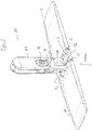
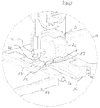
- FIG. 1 FIG. 4 illustrates an exploded view of the holder 10 according to the present invention. The assembled holder 10 is shown in FIG FIG. 2 to see.
- This holder 10 has a handle 28 which is rotatably mounted on an intermediate part 34. This rotatable or pivotable mounting can be locked relative to a pivot axis by means of a locking device 30 in a pivoting position.
- the central part 12 is provided by means of a pivot axis 32.
- two folding wings 14 are mounted by means of two axes.
- a push button 20 is further provided movable, which is partially received in a groove 13 of the central part 12 on the side of the handle 28.
- the handle 28 opposite surfaces of the folding wings 14 and the central portion 12 form the surface which abuts when using the holder in a mop, together with the attached mop cover to the surface to be cleaned.
- the push button 20 itself serves to actuate or to solve the locking device, which will be described in detail later. It is slidably received in the groove 13, but in addition it is received in a hollow cap 21 which is formed on the central part 12 on the side of the groove 13. As such, it is received along a circumferential direction of the central portion 12, wherein he however, protrudes from the central part 12. In this respect he is easily operated from the outside. The details will be described later.
- the two folding wings 14 are flat, plate-like elements whose basic shape is substantially rectangular. On a narrow side of the rectangles, which lies outside when holding a mop cover, they have a substantially smooth edge. On the opposite side provided with through holes projections are provided which can be connected to the central part 12. In this case, the through holes are aligned so that in each of the projections, a through hole is provided which extends parallel to the narrow side of the flap and which has the same diameter for each projection. The through holes are aligned with each other, so that through these through holes a single pivot axis 22 can be passed. These holes are used to connect the respective flap 14 with the central part 12.
- the projection 18a plays a role in the locking of the folding wings 14 with respect to the central part 12.
- This projection 18a is provided at such a position of the projected narrow side of the folding wing 14 that it can penetrate into a later-mentioned passage 19 of the central part.
- At its longitudinal end, it has a bevelled surface 18, which extends in an assembled holder 10 obliquely downwards.
- the middle part 12 is a body that can be described essentially as a two-part.
- a flat, rectangular part on the longitudinal sides of the narrow-side projections and recesses of the folding wings 14 matching recesses and Projections are provided. These projections are provided with through holes that fit to the through holes in the flaps 14, so that rod-like pivot axes 22 can be inserted through them, whereby the folding wings 14 are pivotally connected to the central part 12.
- This attachment 21 is formed integrally with the lower part and has substantially the shape of a cuboid with rounded corners.
- a groove 13 is formed in the flat, rectangular part of the middle part 12, which in cross section has a trapezoidal shape, which tapers downwards.
- This groove 13 extends along the longitudinal direction of the flat, rectangular portion of the central portion 12 of the cap 21 to the opening of the attachment 21 opposite end of the central portion 12th
- two bores 33 are further provided in the attachment 21, which extend parallel to the underside of the central part 12. These pass through the walls of the cavity defined by the attachment 21 in alignment.
- the push button 20 is used in the assembled state.
- This push button 20 has the shape of a hollow body which is open on one side. One could also call this form a hollow cuboid, with one side open.
- the push button 20 is inserted with this open side opposite the closed side of the attachment 21 into the cavity of the attachment 21.
- the push button 20 also has on the two sides, which face the holes 33 after insertion into the attachment 21, each holes 37, which are aligned with the holes 33. However, these holes 37 are elongated. The longitudinal direction of these elongated holes 37 is, after insertion of the push button 20, parallel to the longitudinal direction of the central part 12. Thus, one can use through the holes 33 and 37, an axis 32, without preventing the push button 20, with respect to the attachment 21 along the longitudinal direction of the central portion 12 to be moved.
- a spring 36 which serves to bias the push button 20 toward the opening of the cap 21, d. H. this spring pushes the push button 20 to the outside.
- the spring is, e.g. by corresponding projections in the push button 20 and top 21, held so that they can not slip with respect to these two components.
- the tension of the spring 36 is important in that it achieves the automatic locking previously described.
- a contact part 16 On the lower side of the push-button 20 when inserted into the attachment 21, there is a contact part 16, which has the shape of a trapezoid tapering downwards in cross-section perpendicular to the longitudinal direction of the middle part 12. This trapezoid fits into the groove 13 from the shape, ie you can use this projection in the groove 13 and move in this groove 13 along the longitudinal direction of the central part 12.
- this passage 19 allows, in addition to the already mentioned opening of the Attachment 21, a further access to the interior of the article 21.
- the passage 19 also divides the flat rectangular portion of the central portion 12 in two parts, thereby extending substantially parallel to the narrow sides of the flat rectangular portion. These two parts are held together by the attachment 21.
- an intermediate part 34 is placed at the top of essay 21, d. H. on the side opposite the bottom of the holder 10, an intermediate part 34 is placed.
- This intermediate part 34 has two arms 35, each having a bore. By means of this bore they can be connected to the attachment 21 and the push button 20. More specifically, the axle 32 is inserted through the bore of one of the arms 35 of the intermediate member 34. It then passes through the hole 33 of the cap 21 and through one of the holes 37 of the push button 20 therethrough. Then it passes through the other hole 37 of the push button 20 and through the associated hole 33 of the cap 21 therethrough, to finally penetrate into the other hole of the other arm 35 of the intermediate part 34. As a result, the intermediate part 34, the middle part 12 and the push button 20 are connected.
- the axis 32 not only has the task of providing a pivotable connection between the handle 28 and the holder 10, but also serves to prevent slipping out of the push button 20.
- the intermediate part 34 is another hole 34 a, via which the handle 28 is mounted pivotably with respect to the intermediate part 34.
- FIG. 3 To better understand the locking mechanism, we will see below FIG. 3 to go into detail. In this Figurines are not all in anymore FIGS. 1 and 2 used reference numerals in order not to complicate an understanding.
- FIG. 3 will be one opposite the FIG. 2 enlarged partial sectional view of the holder 10 shown in the locked state.
- the lower sides of the folding wings 14 and the middle part 12 substantially form a plane.
- the push button 20 is pushed as far as possible to the outside, ie until the opening of the attachment 21 opposite edges of its holes 37 abuts the axis 32 and thereby prevents further movement of the push button 20.
- the abutment member 16 is located within the passage 19.
- an interaction with the projections 18a of the folding wings 14 is possible.
- the stops 18 of the folding wing 14 and the trapezoidal leg surfaces of the abutment part 16 lie flat against one another, so that a pivoting of the folding wings 14 downwards is prevented.
- the contact part 17 is moved out of the passage 19.
- an engagement of the stops 18 and system part stops 17 is no longer possible. This has the consequence that the lock is released, whereby the folding wings 14 can be pivoted.
- the system part stops 17 of the system part 16 together with the surfaces 18 of the projections 18a form the locking device.
- the surfaces 17 and 18a are, in the locked state, flat against each other. Since the surfaces 17 and, accordingly, the surfaces 18 in the locked state are directed obliquely downwards, the projections 18a can not be pivoted upwards. Furthermore, pivoting of the projections 18a downwards is prevented by a similar arrangement. This has the consequence that in the folding wings 14 of that part which extends from the pivot axes 22 to the outside, can not be moved down in the locked state. In this respect, a pivoting of the folding wings 14 is prevented in this state, the holder is thus, as regards the positioning of the folding wings 14 with respect to the central part 12, locked. Now, as is the case, ensuring that the lower surfaces of the folding wings 14 and the middle part 12 form a plane, the holder can thus be used well for holding mop covers and thus for cleaning surfaces without the holder 10 significantly deformed.
Description
Die vorliegende Erfindung betrifft einen Halter für Bezüge von Wischmops.The present invention relates to a holder for covers of mops.
Bei dem Reinigen von großen flachen Oberflächen, wie zum Beispiel Linoleumfußböden, aber auch gefliesten Flächen wie sie in Sanitäreinrichtungen oder anderen Räumen vorhanden sind, in denen auf eine hohe Hygiene Wert gelegt wird, werden oftmals Wischmops eingesetzt. Bei einem Wischmop handelt es sich um ein Reinigungsgerät, das eine an einem langen Stiel befestigte verschwenkbar gelagerte Bodenplatte aufweist.In the cleaning of large flat surfaces, such as linoleum floors, but also tiled surfaces as they are available in sanitary facilities or other spaces in which high hygiene value is placed, mops are often used. A mop is a cleaning device that has a pivotally mounted bottom plate attached to a long handle.
An dieser Bodenplatte (Halter) ist, vom Stiel aus gesehen an der entgegengesetzten Seite, ein Wischbezug vorgesehen, der über den Boden bewegt werden kann. Dieser wird durch die Bodenplatte aufgespannt und liegt somit im Wesentlichen straff an dieser an. Da hierdurch die Form des Wischbezugs durch die Bodenplatte vorgegeben wird und diese im Wesentlichen flach ist, hat auch der Wischbezug eine im Wesentlichen flache Oberfläche. Diese kann über die zu reinigende Fläche gewischt werden, wodurch man große Bodenflächen gut reinigen kann. Dies wird insbesondere dadurch unterstützt, dass der Wischbezug häufig mit Fransen versehen ist, die im Normalfall bis zu ungefähr 10 cm lang sind. Der Wischbezug kann ferner mit Wasser getränkt werden, welches auch ein Reinigungsmittel enthalten kann, wodurch der Reinigungseffekt verstärkt wird.At this bottom plate (holder), seen from the handle on the opposite side, a mop cover is provided, which can be moved over the ground. This is stretched by the bottom plate and thus lies substantially taut on this. As a result, the shape of the mop cover is predetermined by the bottom plate and this is substantially flat, and the mop cover has a substantially flat surface. This can be wiped over the surface to be cleaned, which makes it easy to clean large floor surfaces. This is particularly supported by the fact that the mop cover is often provided with fringes, which are normally up to about 10 cm long. The mop cover can also be soaked with water, which may also contain a cleaning agent, whereby the cleaning effect is enhanced.
Wie sich jedoch aus dem oben Genannten ergibt, ist ein Problem, dass der Wischbezug bei Gebrauch Schmutz aufnimmt und dadurch nach einiger Zeit seine Reinigungswirkung verliert. Ein weiteres Problem ist die Abnutzung des Wischbezugs nach längerem Gebrauch. Da dies jedoch auf den Wischbezug alleine, nicht jedoch auf die Bodenplatte zutrifft, wäre es nicht sinnvoll, den Wischbezug zusammen mit der Bodenplatte auszutauschen. Daher wird gemäß dem Stand der Technik vorgesehen, die Bodenplatte und den Wischbezug so zu gestalten, dass der Wischbezug austauschbar ist.However, as apparent from the above, there is a problem that the mop cover picks up dirt in use and thereby loses its cleaning effect after some time. Another problem is the wear of the Mop cover after prolonged use. However, since this applies to the mop cover alone, but not on the bottom plate, it would not make sense to replace the mop cover together with the bottom plate. Therefore, it is provided according to the prior art, to make the bottom plate and the mop cover so that the mop cover is interchangeable.
Dies wird gemäß dem Stand der Technik dadurch erzielt, dass man die Bodenplatte im Wesentlichen in der Form eines länglichen Rechtecks vorsieht, welches bezüglich seiner Längsrichtung zusammengeklappt werden kann. Hierdurch kommen die längsseitigen Enden nahe zusammen. In einem solchen Zustand kann ein entsprechend dimensionierter Wischbezug, der an seinen längsseitigen Enden Taschen aufweist, über die längsseitigen Enden der geklappten Bodenplatte geschoben werden. Wenn man diese Bodenplatte nun von dem geklappten Zustand in den ebenen Zustand überführt, wird der Wischbezug durch die Taschen und durch die Bodenplatte gerade gezogen und auch durch diese gehalten, d. h. er kann nicht von der Bodenplatte herunterrutschen. Gleichzeitig kann man jedoch durch erneutes Zusammenfalten der Bodenplatte den Bezug leicht von dieser entfernen.This is achieved according to the prior art by providing the bottom plate substantially in the form of an elongated rectangle, which can be folded with respect to its longitudinal direction. As a result, the longitudinal ends come close together. In such a condition, a suitably sized mop cover having pockets at its longitudinal ends may be slid over the longitudinal ends of the folded bottom panel. When this bottom plate is now transferred from the folded state to the flat state, the mop cover is pulled straight through the pockets and through the bottom plate and also held by them, d. H. he can not slip off the bottom plate. At the same time, however, by refolding the bottom plate, it is easy to remove the cover from it.
Ein Problem, was hierbei jedoch auftritt, ist, dass man zum einen verhindern will, dass die Bodenplatte des Wischmops ungewollt zusammengefaltet wird, da hierdurch der Wischbezug bei Benutzung abfallen könnte. Auf der anderen Seite will man aber auch einen Wischmop haben, bei dem der Wischbezug bei Bedarf leicht austauschbar ist und der, insbesondere in Anbetracht des hohen Zeitdrucks u.a. bei Reinigungsfirmen, schnell wechselbar ist.A problem, which occurs here, however, is that one wants to prevent the one hand, that the bottom plate of the mop is folded unintentionally, as a result, the mop cover could fall off in use. On the other hand, one also wants to have a mop in which the mop cover is easily replaceable if necessary and which, in particular in view of the high time pressure u.a. at cleaning companies, quickly changeable.
Aus der
Aus der
Die
Die vorliegende Erfindung zielt darauf ab, einen Halter für einen Wischmop bereitzustellen, der so gestaltet ist, dass der Wischbezug leicht austauschbar ist.The present invention aims to provide a holder for a mop which is designed so that the mop cover is easily replaceable.
Eine Lösung dieser Aufgabe ergibt sich durch den Halter zum Halten von Wischbezügen für Reinigungsmittel nach Anspruch 1. Bevorzugte Ausführungsformen sind in den abhängigen Ansprüchen 2 bis 8 beschrieben.A solution to this problem results from the holder for holding mop covers for detergent according to claim 1. Preferred embodiments are described in the dependent claims 2 to 8.
Gemäß Anspruch 1 weist ein Halter zum Halten von Wischbezügen für Reinigungsmittel ein Mittelteil, zwei arretierbare Klappflügel, die an dem Mittelteil verschwenkbar gelagert sind, eine Arretiereinrichtung, welche die zwei Klappflügel in einer Schwenkposition bezüglich des Mittelteils arretieren kann, und eine Einrichtung auf, um die Arretierung der arretierten Klappflügel bezüglich des Mittelteils zu lösen, sodass die Klappflügel verschwenkt werden können. Anders gesagt ist die Bodenplatte des Wischmops in drei Teile geteilt. Zum einen gibt es ein Mittelteil, das zwischen den beiden Klappflügeln liegt. Die Klappflügel können um dieses Mittelteil verschwenkt werden, sodass sie zwischen einer ersten Konfiguration, in der die beiden Klappflügel und das Mittelteil zusammen an ihrer Unterseite eine Ebene bilden (ebene Konfiguration), und einer zweiten Konfiguration verschwenkt werden können, in der die beiden Klappflügel zusammen mit dem Mittelteil eine im Wesentlichen U-förmige Gestalt ausbilden. In der zweiten Konfiguration kann ein Wischbezug auf den Halter montiert werden. Dieser Wischbezug wird durch an dessen Enden vorhandene Taschen in der ersten Konfiguration durch den Halter gehalten und kann somit nicht mehr von diesem ungewollt herabrutschen. Die verschwenkbare Lagerung der Klappflügel bzgl. des Mittelteils kann zum Beispiel durch eine Achsenlagerung erfolgen, sie kann jedoch auch dadurch erfolgen, dass die Klappflügel mit dem Mittelteil mittels eines flexiblen Verbindungsstücks verbunden sind.According to claim 1, a holder for holding mop covers for cleaning means comprises a central part, two lockable folding wings, which are pivotally mounted on the central part, a locking device which can lock the two folding wings in a pivotal position relative to the central part, and means to the Detach lock the locked folding wings with respect to the central part, so that the folding wings can be pivoted. In other words, the bottom plate of the mop is divided into three parts. On the one hand, there is a middle section, which lies between the two folding wings. The folding wings can be pivoted about this central part, so that they can be pivoted between a first configuration in which the two folding wings and the central part together form a plane on its underside (planar configuration), and a second configuration in which the two folding wings together form a substantially U-shaped shape with the middle part. In the second configuration, a mop cover can be mounted on the holder. This mop cover is held by existing at its ends pockets in the first configuration by the holder and thus can no longer slip down from this unintentionally. The pivotable mounting of the folding wings with respect. Of the middle part can be done for example by an axle bearing, but it can also be done by the fact that the folding wings are connected to the middle part by means of a flexible connector.
Die Arretiereinrichtung stellt sicher, dass die beiden Klappflügel in der ersten Konfiguration, d.h. einer Position gehalten werden können, in welcher der Halter eine ebene Bodenplatte bildet und sich nicht unbeabsichtigt "zusammenfaltet".The locking device ensures that the two folding wings can be kept in the first configuration, ie a position in which the holder is a flat Bottom plate forms and does not unintentionally "folds".
Ein Merkmal der vorliegenden Erfindung ist, dass die Arretiereinrichtung zu dem Zustand hin vorgespannt ist, in dem die zwei Klappflügel arretiert sind. Hierdurch arretiert der Halter bei gelöster Arretierung beim Bewegen der zwei Klappflügel hin zu einem Zustand, in dem die unteren Oberflächen der zwei Klappflügel im Wesentlichen in einer Ebenen liegen, die Klappflügel selbsttätig mittels der Arretiereinrichtung. Anders gesagt bedeutet dies, dass ein Benutzer keine separate Handlung zum Arretieren der Klappflügel vornehmen muss, wenn man diese von der U-förmigen Konfiguration in die ebene Konfiguration überführen will. Es reicht aus, nur die Klappflügel zu verschwenken, was man zum Beispiel dadurch machen kann, dass man diese gegen einen zu reinigenden Fußboden drückt. Hierdurch spreizen sich diese nach außen auf, was, wie im Anspruch beschrieben, zu einer automatischen Arretierung führt. Da hierdurch kein separater Arretierungsschritt zusätzlich zu dem Spreizen nötig ist führt dies dazu, dass man den Halter leicht mit einem neuen Wischbezug versehen kann.A feature of the present invention is that the locking device is biased to the state in which the two folding wings are locked. As a result, the holder locks when the lock is released when moving the two folding wings toward a state in which the lower surfaces of the two folding wings are substantially in a plane, the folding wings automatically by means of the locking device. In other words, this means that a user does not have to make a separate action for locking the folding wings if they want to transfer them from the U-shaped configuration to the planar configuration. It is sufficient to only pivot the folding wings, which can be done, for example, by pressing them against a floor to be cleaned. As a result, they spread outwards, which, as described in the claim, leads to an automatic lock. Since this does not require a separate locking step in addition to the spreading, this leads to the holder being easily provided with a new mop cover.
Erfindungsgemäß weist die Arretiereinrichtung für zumindest einen der Klappflügel, bevorzugt für beide, einen Anschlag am Klappflügel und ein bezüglich des Mittelteils beweglich vorgesehenes Anlageteil auf, welches mindestens einen Anlageteilanschlag aufweist. Hierbei sind der Anschlag am Klappflügel und der Anlageteilanschlag bei Arretierung des Klappflügels miteinander in Eingriff, während sie bei Lösen der Arretierung durch Bewegen des Anlageteils außer Eingriff geraten. Anders gesagt ist ein Anlageteil vorgesehen, an welches der jeweilige Klappflügel/die Klappflügel bei Arretierung anstoßen können. Diese sind durch den dadurch entstehenden Kontakt mit dem Mittelteil sicher arretiert und blockiert, weshalb sich die Bodenplatte des Mops bei Benutzung nicht oder nur gering verformt.According to the invention, the locking device for at least one of the folding wings, preferably for both, a stop on the folding wing and a relative to the central part movably provided part of the plant, which has at least one partial investment stop. In this case, the stop on the folding wing and the plant sub-stop when locking the folding wing are engaged, while they disengage upon release of the lock by moving the system part. In other words, a system part is provided, to which the respective folding wing / the folding wings can abut when locking. These are securely locked and blocked by the resulting contact with the middle part, which is why the bottom plate of the pug does not deform or only slightly deformed during use.
Weiterhin ist das Anlageteil im Wesentlichen parallel zu der Schwenkachse des Klappflügels beweglich. Insbesondere wird hierbei bevorzugt, dass das Anlageteil lediglich im Wesentlichen parallel zu der Schwenkachse des Klappflügels beweglich ist, d. h. dass man dieses nicht oder nur geringfügig in einer anderen Richtung bewegen kann. Ein Vorteil dieses Merkmals für sich genommen ist, dass man hierdurch eine gute und einfache Entformung des Anlageteils sicherstellt. Insbesondere wird es eine Reinigungsfachkraft nach längerer Arbeit leichter finden, ein Anlageteil im Wesentlichen parallel zu der Schwenkachse der Klappflügel zu entformen als dies zum Beispiel entlang einer Richtung des Stiels möglich wäre.Furthermore, the contact part is movable substantially parallel to the pivot axis of the folding leaf. In particular, it is preferred in this case that the contact part is movable only substantially parallel to the pivot axis of the folding wing, d. H. that you can not move this or only slightly in another direction. An advantage of this feature taken by itself is that it ensures a good and easy demolding of the plant part. In particular, it will be easier for a cleaning specialist to find it easier to remove a piece of equipment essentially parallel to the pivot axis of the folding wings after a relatively long work, for example, than would be possible along a direction of the handle.
Dies hat außerdem als Vorteil, dass ein ungewolltes außer Eingriff Bringen der Anschläge verhindert wird, die bei einer Bewegbarkeit in anderen Richtungen unter Umständen gegeben wäre. So könnte eine Bewegbarkeit senkrecht zu den Schwenkachsen dazu führen, dass das Anlageteil bei Ausüben eines Drucks auf die Klappflügel hoch oder zur Seite gedrückt wird. Dies könnte jedoch dazu führen, dass die entsprechenden Teile außer Eingriff geraten, was zu einem Abrutschen und Abfallen des Wischbezugs führen kann.This also has the advantage that unwanted disengagement of the attacks is prevented, which would be given in a mobility in other directions under certain circumstances. Thus, a mobility perpendicular to the pivot axes could cause the plant part is pressed when exerting pressure on the folding wings up or to the side. However, this could lead to the corresponding parts disengaged, which can lead to slipping and falling of the mop cover.
Es hat sich weiterhin als von Vorteil erwiesen, dass die Einrichtung, um die Arretierung der Klappflügel bezüglich des Mittelteils zu lösen, einen von Hand betätigbaren Druckknopf aufweist. Wenn man diesen betätigt führt dies, bei hinreichend starker Betätigung, zur Lösung der Arretierung. Damit dies möglich ist, ist der Druckknopf mit dem Anlageteil gekoppelt. Der Druckknopf führt bei Betätigung zu einer Bewegung des Anlageteils, was wiederum bei Verschiebung um einen vorbestimmten Weg die Arretierung löst. Anders gesagt befindet sich ein Druckknopf an dem Halter, der sozusagen "per Knopfdruck" ein Lösen der Arretierung ermöglicht. Da dieser mit dem Anlageteil gekoppelt ist, wird hierdurch eine leichte Lösung der Arretierung ermöglicht. Somit kann man auch nach längerer Arbeit an dem Wischmop den Wischbezug leicht und problemlos entfernen, da sich ein solcher Druckknopf auch nach längerer Arbeit und entsprechender Erschöpfung der Muskeln gut betätigen lässt.It has also been found to be advantageous that the means for releasing the locking of the folding wings with respect to the central part comprises a manually operable push-button. If one operates this leads, if sufficiently strong operation, to solve the lock. For this to be possible, the push button is coupled to the system part. The push button results in actuation to a movement of the system part, which in turn triggers the lock when displaced by a predetermined path. In other words, there is a push button on the holder, which allows a release of the lock, so to speak "by pressing a button". Since this is coupled to the plant part, this is a easy solution of the lock allows. Thus, you can easily and easily remove even after prolonged work on the mop the mop cover, since such a push button can be well operated even after prolonged work and appropriate exhaustion of the muscles.
In diesem Zusammenhang ist es von Vorteil, dass man das Anlageteil und den Druckknopf einstückig ausbildet, d. h. dass diese aus einer einzelnen Komponente bestehen. Hierdurch wird eine einfache Gestaltung des Wischmops ermöglicht, es ist nunmehr keine komplizierte Kopplung zwischen Anlageteil und Druckknopf nötig.In this context, it is advantageous that the system part and the push button is formed in one piece, d. H. that these consist of a single component. This allows a simple design of the mop, it is now no complicated coupling between the system part and push button needed.
Bei dem bereits vorher beschriebenen Anlageteilanschlag hat es sich als von Vorteil erwiesen, wenn dieser nach unten gerichtet ist, insbesondere wenn dieser schräg nach unten gerichtet ist. Hierbei bezeichnet die Richtung "nach unten" die Richtung, die sich bei dem Halter senkrecht von der Seite erstreckt, auf der im arretierten Zustand durch das Mittelteil und die beiden Klappflügel eine Ebene gebildet wird. Anders gesagt ist es diejenige Seite, die, bei Gebrauch, einem Stiel und einer gegebenenfalls mit dem Halter verbundenen Handhabe entgegengesetzt ist. Insofern handelt es sich um die Seite des Halters, die bei normalem Gebrauch an der zu reinigenden Oberfläche anliegt. Ferner ist der Anschlag am Klappflügel bevorzugt derartig ausgerichtet, dass er im arretierten Zustand des Klappflügels flächig an dem Anlageteilanschlag anliegt.In the previously described sub-investment stop, it has proved to be advantageous if this is directed downward, especially if this is directed obliquely downwards. Here, the direction "down" refers to the direction perpendicular to the holder extends from the side on which a plane is formed in the locked state by the central part and the two folding wings. In other words, it is that side which, in use, is opposite a stem and, if necessary, a handle connected to the holder. In this respect, it is the side of the holder, which rests on the surface to be cleaned in normal use. Further, the stop on the folding wing is preferably aligned such that it rests flat in the locked state of the folding leaf on the plant sub-stop.
Anders gesagt bedeutet dies, dass der Anlageteilanschlag zumindest teilweise nach unten zeigt (auch wenn er vorzugsweise geneigt ist). Dadurch, dass der Anschlag am Klappflügel bevorzugt im arretierten Zustand flächig an dem Anlageteilanschlag anliegt, gibt es einen guten Kontakt zwischen diesen beiden Anschlägen. Insofern wird eine gute Arretierung sichergestellt. Durch die Ausrichtung des Anlageteilanschlags nach unten, vorzugsweise schräg nach unten kann eine ungewollte Verschwenkung der Klappflügel gut und zuverlässig verhindert werden.In other words, this means that the abutment part stop at least partially downwards (even if it is preferably inclined). Due to the fact that the stop on the folding wing preferably lies flat against the abutment part stop in the locked state, there is good contact between these two stops. In this respect, a good lock is ensured. Due to the orientation of the system sub-stop down, preferably obliquely below an unwanted pivoting of the folding wings can be well and reliably prevented.
Zusätzlich ist es von Vorteil, wenn die Schwenkachsen aller Klappflügel im Wesentlichen parallel zueinander sind. Hierdurch kann man den Halter leicht zusammenlegen und dadurch den Wischbezug entfernen.In addition, it is advantageous if the pivot axes of all folding wings are substantially parallel to each other. This allows you to easily fold the holder and thereby remove the mop cover.
Bei den genannten Ausführungsformen ist es ferner von Vorteil, dass es eine weitere Einrichtung gibt, die den Verschwenkbereich zumindest eines bzw. bevorzugt aller arretierbaren Klappflügel in dem nicht-arretierten Zustand einschränkt. Hierdurch wird der Verschwenkungsbereich so eingeschränkt, dass die Klappflügel einen Mindestwinkel miteinander einschließen müssen. Dies bedeutet, dass sie nicht-arretierten Zustand einen Winkel von jeweils mindestens 10°, bevorzugt 20°, stärker bevorzugt 30° mit der Richtung nach unten einschließen. Dies ist bei der Benutzung von Vorteil. Anders gesagt ist es bei der Verwendung besonders von Vorteil, wenn die beiden Klappflügel einen Winkel von in etwa 60°, d.h. in etwa 55° bis 65°, miteinander symmetrisch zu der Richtung nach unten einschließen. So wird dadurch verhindert, dass die Klappflügel nach Lösen der Arretierung vollständig nach unten klappen. Dies würde ein Versehen des Halters mit einem Wischbezug erschweren. Dadurch, dass die Klappflügel mit den verschiedenen Winkeln nach außen gespreizt sind kann man diese leicht in den ebenen Zustand der Unterseite überführen und gleichzeitig den Wischbezug aufspannen, indem man den Halter, mit den Klappflügeln nach unten, einfach gegen die zu säubernde Oberfläche, auf welcher der Wischbezug liegt, drückt. Dies bringt, wie aus dem oben Genannten ersichtlich ist, Vorteile mit sich was die leichte Benutzbarkeit angeht.In the aforementioned embodiments, it is also advantageous that there is a further device that limits the pivoting range of at least one or preferably all lockable folding wings in the unlocked state. As a result, the Verschwenkungsbereich is limited so that the folding wings must include a minimum angle with each other. This means that they include an angle of at least 10 °, preferably 20 °, more preferably 30 ° with the direction downwards in the unlocked state. This is an advantage in use. In other words, in use, it is particularly advantageous if the two folding wings enclose an angle of approximately 60 °, ie approximately 55 ° to 65 °, symmetrical to the direction downwards. This prevents the folding wings from completely falling down after releasing the lock. This would make it more difficult for the holder to be fitted with a mop cover. The fact that the folding wings are spread with the different angles to the outside you can easily convert them into the flat state of the bottom and at the same time span the mop cover by the holder, with the folding wings down, just against the surface to be cleaned, on which the mop cover is, presses. This brings, as can be seen from the above, advantages in terms of ease of use.
Die genannte Verschwenkungsbereich-Einschränkeinrichtung weist vorteilhaft einen Mittelteilanschlag auf, der ortsfest bezüglich des Mittelteils vorgesehen ist. Das heißt, dass es an dem Mittelteil einen weiteren Anschlag gibt, der mit dem zugehörigen Klappflügel, insbesondere bevorzugt dem bereits definierten Anschlag des Klappflügels, im nicht-arretierten Zustand in Eingriff kommen kann. Hierdurch wird auf einfache Weise, jedoch gleichzeitig zuverlässig, der Verschwenkungsbereich eingeschränkt. Durch die einfache Bauweise dieser Einrichtung lassen sich die Produktionskosten verringern.Said Verschwenkungsbereich-restricting means advantageously has a central part stop, which is provided stationary with respect to the central part. This means that there is a further stop at the central part, which can engage the associated folding wing, in particular preferably the already defined stop of the folding wing, in the unlocked state. As a result, the Verschwenkbereich is restricted in a simple manner, but at the same time reliable. The simple design of this device can reduce production costs.
Bei den genannten bevorzugten Ausführungsformen ist es außerdem von Vorteil, dass die selbsttätige Arretierung in dem Zustand stattfindet, in dem die unteren Oberflächen der zwei arretierbaren Klappflügel im Wesentlichen in einer Ebene liegen. Hierdurch wird die Benutzbarkeit des Mops im arretierten Zustand sichergestellt.In the said preferred embodiments, it is also advantageous that the automatic locking takes place in the state in which the lower surfaces of the two lockable folding wings lie substantially in one plane. This ensures the usability of the pug in the locked state.
Ferner wird bevorzugt, dass an dem Mittelteil eine Handhabe vorgesehen ist, die um zwei Achsen bezüglich des Mittelteils verschwenkbar und vorzugsweise in einer Drehposition um eine Achse arretierbar ist. Hierdurch kann man den Halter leicht zum Beispiel unter Möbeln einsetzen, insbesondere wenn man einen Stiel an der Handhabe befestigt.Furthermore, it is preferred that a handle is provided on the central part, which is pivotable about two axes with respect to the central part and preferably in a rotational position about an axis. As a result, you can easily use the holder, for example, under furniture, especially if you attach a handle to the handle.
- Figur 1FIG. 1
- zeigt eine Explosivdarstellung eines Halters gemäß der vorliegenden Erfindung.shows an exploded view of a holder according to the present invention.
- Figur 2FIG. 2
- zeigt den zusammengebauten Halter gemäß der Erfindung in einem arretierten Zustand.shows the assembled holder according to the invention in a locked state.
- Figur 3FIG. 3
- zeigt eine partielle Schnittansicht eines Details des Halters gemäß der vorliegenden Erfindung im arretierten Zustand.shows a partial sectional view of a detail of the holder according to the present invention in the locked state.
- Figur 4FIG. 4
- zeigt eine Gesamtansicht des Halters gemäß der vorliegenden Erfindung im nicht-arretierten Zustand in einer partiellen Schnittansicht.shows an overall view of the holder according to the present invention in the unlocked state in a partial sectional view.
- Figur 5FIG. 5
-
ist eine Detailansicht des Halters gemäß der
Figur 4 .is a detail view of the holder according to theFIG. 4 , - Figur 6FIG. 6
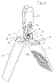
- zeigt eine Seitenansicht des Halters gemäß der vorliegenden Erfindung.shows a side view of the holder according to the present invention.
Dieser Halter 10 weist eine Handhabe 28 auf, die an einem Zwischenteil 34 drehbar gelagert ist. Diese drehbare bzw. verschwenkbare Lagerung kann bezüglich einer Schwenkachse mittels einer Arretiereinrichtung 30 in einer Verschwenkposition arretiert werden. An dem Zwischenteil 34 ist mittels einer Verschwenkachse 32 das Mittelteil 12 vorgesehen. An diesem Mittelteil 12 sind mittels zweier Achsen 22 zwei Klappflügel 14 angebracht. An dem Mittelteil 12 ist ferner ein Druckknopf 20 beweglich vorgesehen, der teilweise in eine Nut 13 des Mittelteils 12 auf der Seite der Handhabe 28 aufgenommen ist. Die der Handhabe 28 entgegengesetzten Flächen der Klappflügel 14 und des Mittelteils 12 bilden die Oberfläche, die bei Benutzung des Halters in einem Wischmop zusammen mit dem daran angebrachten Wischbezug an der zu reinigenden Oberfläche anliegt.This
Der Druckknopf 20 selbst dient zur Betätigung bzw. zur Lösung der Arretiereinrichtung, die später im Detail beschrieben werden wird. Er ist in die Nut 13 verschiebbar aufgenommen, wobei er jedoch zusätzlich in einem hohlen Aufsatz 21, der auf dem Mittelteil 12 auf der Seite der Nut 13 ausgebildet ist, aufgenommen ist. Insofern wird er entlang einer Umfangsrichtung von dem Mittelteil 12 aufgenommen, wobei er jedoch aus dem Mittelteil 12 hervorsteht. Insofern ist er von außen leicht betätigbar. Die Details werden später beschrieben werden.The
Bei den beiden Klappflügeln 14 handelt es sich um flache, plattenähnliche Elemente, deren Grundform im Wesentlichen rechteckig ist. An einer Schmalseite der Rechtecke, die bei dem Halten eines Wischbezugs außen liegt, haben diese eine im Wesentlichen glatte Kante. An der gegenüberliegenden Seite sind mit Durchgangslöchern versehene Vorsprünge vorgesehen, die mit dem Mittelteil 12 verbunden werden können. Dabei sind die Durchgangslöcher so ausgerichtet, dass in jedem der Vorsprünge ein Durchgangsloch vorgesehen ist, welches sich parallel zur Schmalseite des Klappflügels erstreckt und welches für jeden Vorsprung den gleichen Durchmesser hat. Die Durchgangslöcher fluchten miteinander, sodass durch diese Durchgangslöcher eine einzige Verschwenkachse 22 hindurchgeführt werden kann. Diese Löcher werden zur Verbindung des jeweiligen Klappflügels 14 mit dem Mittelteil 12 verwendet.The two
Unter den genannten Vorsprüngen der Klappflügel 14 verdient der Vorsprung 18a besondere Erwähnung da dieser bei der Arretierung der Klappflügel 14 bezüglich des Mittelteils 12 eine Rolle spielt. Dieser Vorsprung 18a ist an einer solchen Position der mit Vorsprüngen versehenen Schmalseite des Klappflügels 14 vorgesehen, dass er in einen später zu erwähnenden Durchlass 19 des Mittelteils eindringen kann. An seinem längsseitigen Ende weist er eine abgeschrägte Oberfläche 18 auf, die in einem zusammengebauten Halter 10 schräg nach unten verläuft.Among the mentioned projections of the
Bei dem Mittelteil 12 handelt es sich um einen Körper, den man im Wesentlichen als zweiteilig beschreiben kann. Zum einen gibt es einen flachen, rechteckigen Teil, an dessen Längsseiten zu den schmalseitigen Vorsprüngen und Ausnehmungen der Klappflügel 14 passende Ausnehmungen und Vorsprünge vorgesehen sind. Diese Vorsprünge sind mit Durchgangslöchern versehen, die zu den Durchgangslöchern in den Klappflügeln 14 passen, sodass stabähnliche Verschwenkachsen 22 durch diese eingesetzt werden können, wodurch die Klappflügel 14 mit dem Mittelteil 12 verschwenkbar verbunden werden. Auf dem Mittelteil 12 gibt es jedoch außerdem einen hohlen Aufsatz 21, der zu einer Schmalseite des Mittelteils 12 hin offen ist, an den anderen Seiten jedoch im Wesentlichen verschlossen ist. Dieser Aufsatz 21 ist einstückig mit dem unteren Teil ausgebildet und hat im Wesentlichen die Form eines Quaders mit abgerundeten Ecken.The
An der Seite des Auslasses 21, die offen ist, ist in dem flachen, rechteckigen Teil des Mittelteils 12 eine Nut 13 ausgebildet, welche im Querschnitt eine Trapezform, die sich nach unten verjüngt, aufweist. Diese Nut 13 erstreckt sich entlang der Längsrichtung des flachen, rechteckigen Teils des Mittelteils 12 von dem Aufsatz 21 bis zum der Öffnung des Aufsatzes 21 gegenüberliegenden Ende des Mittelteils 12.On the side of the
Parallel zu der Schmalseite, d. h. senkrecht zu der Längsrichtung des Mittelteils 12 sind ferner zwei Bohrungen 33 in dem Aufsatz 21 vorgesehen, die sich parallel zur Unterseite des Mittelteils 12 erstrecken. Diese gehen durch die Wände des von dem Aufsatz 21 definierten Hohlraums miteinander fluchtend hindurch.Parallel to the narrow side, d. H. perpendicular to the longitudinal direction of the
In diesen Hohlraum ist im zusammengebauten Zustand der Druckknopf 20 eingesetzt. Dieser Druckknopf 20 hat die Form eines Hohlkörpers, der an einer Seite offen ist. Man könnte diese Form auch als einen hohlen Quader bezeichnen, bei dem eine Seite offen ist. Der Druckknopf 20 ist mit dieser offnen Seite gegenüber der geschlossenen Seite des Aufsatzes 21 in den Hohlraum des Aufsatzes 21 eingesetzt. Der Druckknopf 20 weist ferner an den beiden Seiten, die nach dem Einsetzen in den Aufsatz 21 den Löchern 33 gegenüberliegen, jeweils Löcher 37 auf, die mit den Löchern 33 fluchten. Jedoch sind diese Löcher 37 länglich ausgebildet. Die Längsrichtung dieser länglichen Löcher 37 ist, nach dem Einsetzen des Druckknopfs 20, parallel zur Längsrichtung des Mittelteils 12. Dadurch kann man durch die Löcher 33 und 37 eine Achse 32 einsetzen, ohne dass man den Druckknopf 20 daran hindert, bezüglich des Aufsatzes 21 entlang der Längsrichtung des Mittelteils 12 verschoben zu werden.In this cavity, the
Zwischen dem Druckknopf 20 und der verschlossenen Wand des Aufsatzes 21 ist eine Feder 36 vorgesehen, welche dazu dient, den Druckknopf 20 zu der Öffnung des Aufsatzes 21 hin vorzuspannen, d. h. diese Feder drückt den Druckknopf 20 nach außen. Die Feder wird, z.B. durch entsprechende Vorsprünge im Druckknopf 20 und Aufsatz 21, gehalten, sodass sie nicht bezüglich dieser beiden Komponenten verrutschen kann. Die Spannung der Feder 36 ist, wie aus der späteren Beschreibung deutlich werden wird, dahingehend wichtig, dass hierdurch die selbsttätige Arretierung, die bereits vorher beschrieben wurde, erzielt wird.Between the
An der beim Einsetzen in den Aufsatz 21 unteren Seite des Druckknopfs 20 befindet sich ein Anlageteil 16, welches die Form eines sich nach unten verjüngenden Trapezes im Querschnitt senkrecht zu der Längsrichtung des Mittelteils 12 aufweist. Dieses Trapez passt von der Form her in die Nut 13, d. h. man kann diesen Vorsprung in die Nut 13 einsetzen und in dieser Nut 13 entlang der Längsrichtung des Mittelteils 12 verschieben. Innerhalb des Mittelteils 12 gibt es in demjenigen Bereich, in dem sich der Aufsatz 21 befindet, einen Durchlass 19, in den im zusammengebauten Halter 10 ein entsprechend dimensionierter Vorsprung 18a der Klappflügel eingefügt ist. Dieser Durchlass 19 ist so dimensioniert, dass durch diesen der Vorsprung 18a mit dem Anlageteil 16, bei einer entsprechenden Längsposition des Druckknopfs 20, in Kontakt treten kann. D. h. dieser Durchgang 19 ermöglicht, zusätzlich zu der einen bereits erwähnten Öffnung des Aufsatzes 21, einen weiteren Zugang in das Innere des Aufsatzes 21. Der Durchgang 19 zerteilt außerdem den flachen rechteckigen Teil des Mittelteils 12 in zwei Teile und verläuft dabei im Wesentlichen parallel zu den Schmalseiten des flachen rechteckigen Teils. Diese beiden Teile werden durch den Aufsatz 21 zusammengehalten.On the lower side of the push-
Oben auf den Aufsatz 21, d. h. auf der Seite gegenüber der Unterseite des Halters 10, ist ein Zwischenteil 34 aufgesetzt. Dieses Zwischenteil 34 weist zwei Arme 35 auf, die jeweils eine Bohrung aufweisen. Mittels dieser Bohrung können sie mit dem Aufsatz 21 und mit dem Druckknopf 20 verbunden werden. Genauer gesagt wird die Achse 32 durch die Bohrung eines der Arme 35 des Zwischenteils 34 eingeführt. Sie tritt dann durch das Loch 33 des Aufsatzes 21 und durch eines der Löcher 37 des Druckknopfs 20 hindurch. Anschließend tritt sie durch das andere Loch 37 des Druckknopfs 20 und durch das zugehörige Loch 33 des Aufsatzes 21 hindurch, um schließlich in das andere Loch des anderen Arms 35 des Zwischenteils 34 einzudringen. Hierdurch werden das Zwischenteil 34, der Mittelteil 12 und der Druckknopf 20 verbunden. Insbesondere kann hierdurch verhindert werden, dass der Druckknopf 20 durch die Kraft der Feder 36 aus dem Aufsatz 21 herausgedrückt wird, da die Umgrenzung des Lochs 37 an der Achse 32 anliegen und so ein Herausdrücken durch die Spannkraft der Feder 36 verhindert. Insofern hat die Achse 32 nicht nur die Aufgabe, für eine verschwenkbare Verbindung zwischen der Handhabe 28 und dem Halter 10 zu sorgen, sondern dient auch dazu, ein Herausgleiten des Druckknopfs 20 zu verhindern.At the top of
In dem Zwischenteil 34 befindet sich ein weiteres Loch 34a, über das die Handhabe 28 bezüglich des Zwischenteils 34 verschwenkbar gelagert wird.In the
Um den Arretierungsmechanismus besser zu verstehen, werden wir im Folgenden auf
In
Konkret bedeutet dies, dass eine Oberfläche (Anschlag) 18 des Klappflügels 14 mit den Seitenflächen (Anlageteilanschlag) 17 des Anlageteils 16 in Eingriff ist. Anders gesagt liegen die Anschläge 18 des Klappflügels 14 und die Trapezschenkel-Oberflächen des Anlageteils 16 flächig aneinander an, sodass ein Verschwenken der Klappflügel 14 nach unten verhindert wird. In diesem Zustand ist es jedoch möglich, den Druckknopf 20 durch manuelle Betätigung in den Aufsatz 21 hineinzuschieben. Dadurch wird das Anlageteil 17 aus dem Durchgang 19 hinausbewegt. Hierdurch ist jedoch ein Eingriff der Anschläge 18 und Anlageteilanschläge 17 nicht mehr möglich. Dies hat zur Folge, dass die Arretierung gelöst wird, wodurch die Klappflügel 14 verschwenkt werden können.Concretely, this means that a surface (stop) 18 of the
Allerdings wird diese Verschwenkung durch den oberen Teil des Durchlasses 26, der die Mittelteilanschläge 26 bildet, beschränkt. Gegen diese liegen die Oberflächen 18 an, wenn die maximale Verschwenkung der Klappflügel 14 erreicht wird und verhindern somit eine weitere Verschwenkung.However, this pivoting is limited by the upper part of the
Insofern bilden die Anlageteilanschläge 17 des Anlageteils 16 zusammen mit den Oberflächen 18 der Vorsprünge 18a die Arretiereinrichtung. Die Oberflächen 17 und 18a liegen, im arretierten Zustand, flächig aneinander an. Da die Oberflächen 17 und dementsprechend die Oberflächen 18 im arretierten Zustand schräg nach unten gerichtet sind, können die Vorsprünge 18a nicht nach oben verschwenkt werden. Ferner wird durch eine ähnliche Anordnung auch eine Verschwenkung der Vorsprünge 18a nach unten verhindert. Dies hat zur Folge, dass bei den Klappflügeln 14 derjenige Teil, der sich von den Verschwenkachsen 22 nach außen erstreckt, im arretierten Zustand nicht nach unten bewegt werden kann. Insofern wird in diesem Zustand eine Verschwenkung der Klappflügel 14 verhindert, der Halter ist somit, was die Positionierung der Klappflügel 14 bezüglich des Mittelteils 12 angeht, arretiert. Wenn man nun, wie vorliegend der Fall, dafür sorgt, dass die unteren Oberflächen der Klappflügel 14 und des Mittelteils 12 eine Ebene bilden kann man den Halter somit gut zum Halten von Wischbezügen und somit zum Reinigen von Oberflächen verwenden, ohne dass sich der Halter 10 wesentlich verformt.In this respect, the system part stops 17 of the
Wenn man jedoch den Druckknopf 20 hinreichend tief eindrückt, gelangt man zu dem in
Gleichzeitig wird ein Herausdrücken des Druckknopfs 20 durch die Feder 36 verhindert, da die Vorsprünge 18 nunmehr an ihrer der Öffnung des Aufsatzes 21 entgegengesetzten Fläche an einer entsprechenden Oberfläche des Anlageteils 16 anliegen (siehe
Claims (8)
- Holder (10) for holding wiping covers for cleaning means, in particular wiping covers for mops, having:- a central portion (12),- two lockable folding wings (14) which are mounted pivotably on the central portion (12),- a locking device (17, 18) for locking the two folding wings in a pivot position relative to the central portion (12), and- a device for releasing the lock of the locked folding wings relative to the central portion, so that the folding wings can be pivoted,wherein the locking device (17, 18) is biased towards the state in which the two folding wings are locked, so that when the lock is released upon movement of the two folding wings (14) towards a state in which the lower surfaces of the two folding wings (14) lie substantially in one plane, the holder (10) automatically locks the folding wings by means of the locking device (17, 18),
wherein the locking device has for at least one folding wing (14), preferably for both, a stop (18) on the folding wing (14) and a contact portion (16) which is movable relative to the central portion (12) and which has at least one contact portion stop (17), and wherein the stop (18) on the folding wing (14) and the contact portion stop (17) are engaged with each other when the folding wing (14) is locked and they become disengaged upon release of the lock by movement of the contact portion (16),
characterised in that the contact portion (16) is movable substantially parallel to the pivot shaft (22) of the folding wing (14). - Holder according to claim 1, wherein the device for releasing the lock of the folding wings (14) relative to the central portion (12) has a pushbutton (20) which can be actuated by hand and the actuation of which releases the lock, wherein the pushbutton (20) is coupled to the contact portion (16), and
wherein the pushbutton (20) moves the contact portion (16) upon actuation and releases the lock upon actuation by a predetermined distance. - Holder (10) according to claim 2, wherein the contact portion (16) and the pushbutton (20) are constructed in one piece.
- Holder according to either of claims 2 to 3,wherein the contact portion stop (17) is directed downwards, preferably obliquely downwards, andwherein the stop (18) on the folding wing (14) is preferably oriented in such a way that it abuts against the contact portion stop (17) in planar relationship when the folding wing (14) is in the locked state.
- Holder according to any of the preceding claims, wherein the pivot shafts (22) of all folding wings (14) are substantially parallel to each other.
- Holder (10) according to any of the preceding claims, further havinga device (26) which limits the pivot range of at least one, preferably all lockable folding wings (14) in the unlocked state, wherein this device is preferably designed in such a way that the lower surface of at least one, preferably all lockable folding wings (14) in the unlocked state forms an angle of at least 10°, preferably 20°, more preferably 30°, with the downward direction, measured in the projection along the respective associated pivot shaft (22).
- Holder according to claim 6, wherein the device for limiting the pivot range has a central portion stop (26) which is stationary relative to the central portion (12) and which can be brought into engagement with the associated folding wing (14), preferably the stop (18) of the folding wing (14), and so limits the pivot range.
- Holder according to any of the preceding claims, wherein automatic locking takes place in a state in which the lower surfaces of the two lockable folding wings (14) lie substantially in one plane.
Applications Claiming Priority (1)
| Application Number | Priority Date | Filing Date | Title |
|---|---|---|---|
| PCT/EP2012/063887 WO2014012569A1 (en) | 2012-07-16 | 2012-07-16 | Holder for mop heads |
Publications (2)
| Publication Number | Publication Date |
|---|---|
| EP2872022A1 EP2872022A1 (en) | 2015-05-20 |
| EP2872022B1 true EP2872022B1 (en) | 2016-08-31 |
Family
ID=46545375
Family Applications (1)
| Application Number | Title | Priority Date | Filing Date |
|---|---|---|---|
| EP12737269.6A Active EP2872022B1 (en) | 2012-07-16 | 2012-07-16 | Frame for mop covers |
Country Status (6)
| Country | Link |
|---|---|
| US (1) | US9468354B2 (en) |
| EP (1) | EP2872022B1 (en) |
| DK (1) | DK2872022T3 (en) |
| ES (1) | ES2604199T3 (en) |
| PL (1) | PL2872022T3 (en) |
| WO (1) | WO2014012569A1 (en) |
Families Citing this family (5)
| Publication number | Priority date | Publication date | Assignee | Title |
|---|---|---|---|---|
| DE102014008954B3 (en) * | 2014-06-23 | 2015-09-10 | Carl Freudenberg Kg | Mop cover and mop |
| NL2016570B1 (en) * | 2016-04-08 | 2017-11-02 | Bahri Boudali | Cleaning head, combination of a cleaning head, a water-permeable bag and cleaning agents, and combination of a cleaning head and a bucket with a pump. |
| US10842343B2 (en) * | 2018-06-08 | 2020-11-24 | Contec Inc. | Cleaning tool with adjustable tensioner and related method |
| CN110623611B (en) * | 2018-06-25 | 2021-03-12 | 丁明哲 | Folding flat mop |
| TWI657783B (en) * | 2018-06-25 | 2019-05-01 | 丁明哲 | Folding flat mop |
Family Cites Families (3)
| Publication number | Priority date | Publication date | Assignee | Title |
|---|---|---|---|---|
| DE4011713A1 (en) * | 1990-04-11 | 1991-10-17 | Ewu Ag | CLEANER |
| IT239177Y1 (en) | 1995-01-26 | 2001-02-19 | Cervellin Sergio | STRAW TYPE WET Broom |
| DE102005044507A1 (en) | 2005-09-16 | 2007-03-22 | Leifheit Ag | Foldable wiper plate |
-
2012
- 2012-07-16 ES ES12737269.6T patent/ES2604199T3/en active Active
- 2012-07-16 EP EP12737269.6A patent/EP2872022B1/en active Active
- 2012-07-16 WO PCT/EP2012/063887 patent/WO2014012569A1/en active Application Filing
- 2012-07-16 US US14/415,174 patent/US9468354B2/en active Active
- 2012-07-16 DK DK12737269.6T patent/DK2872022T3/en active
- 2012-07-16 PL PL12737269T patent/PL2872022T3/en unknown
Also Published As
| Publication number | Publication date |
|---|---|
| EP2872022A1 (en) | 2015-05-20 |
| ES2604199T3 (en) | 2017-03-03 |
| DK2872022T3 (en) | 2017-01-02 |
| WO2014012569A1 (en) | 2014-01-23 |
| US9468354B2 (en) | 2016-10-18 |
| PL2872022T3 (en) | 2017-04-28 |
| US20150208894A1 (en) | 2015-07-30 |
Similar Documents
| Publication | Publication Date | Title |
|---|---|---|
| DE4110830C1 (en) | ||
| EP2872022B1 (en) | Frame for mop covers | |
| DE102006012754A1 (en) | Surgical instrument | |
| EP0451443A1 (en) | Cleaning device | |
| DE102005013901A1 (en) | Stand for a Christmas tree comprises a clamping device having a tension lever which when triggered against the direction of the tensioning movement moves a first lock from the teeth of a restraining wheel | |
| EP3048992B1 (en) | Surgical retractor with removable actuating element | |
| DE3719984C2 (en) | ||
| DE10206854C1 (en) | Pull-out lock for drawers arranged one above the other | |
| DE19653897B4 (en) | Guide arrangement for a door element | |
| DE60035081T2 (en) | Device for quickly coupling and releasing a tool to a boom | |
| EP3153115B1 (en) | Bone punch with captive punching slide | |
| WO2013004326A2 (en) | Flat mop and support plate therefor | |
| EP0182089A1 (en) | Flat wringing apparatus for mops | |
| WO2017207592A1 (en) | Mopping implement and mopping system having a mopping implement | |
| EP1055487A1 (en) | Pliers with parallel jaws | |
| DE2461003A1 (en) | DEVICE FOR SPREADING SPRINGS OR PISTON RINGS OR THE SAME | |
| DE19931953A1 (en) | Mounting for end of slat on longitudinal strut in frame comprises base mounting attached to longitudinal strut, slide attached to this and to support for slat, and locking device including movable clip which fits free side of mounting | |
| CH716756B1 (en) | Assembly device for the detachable assembly of a set on a toilet body. | |
| DE3809730C2 (en) | ||
| DE4303993C2 (en) | Floor mop | |
| DE102019133319B4 (en) | Underfloor installation component | |
| EP3251576B1 (en) | Wiping system with a wiping device and a mobile storage box | |
| DE202020100273U1 (en) | Assembly device for the detachable assembly of a set on a toilet body | |
| DE10000100C1 (en) | Device for hanging and hanging curtains, as well as curtain hooks for this device | |
| DE112021006712T5 (en) | Spreader for tubular footwear articles |
Legal Events
| Date | Code | Title | Description |
|---|---|---|---|
| PUAI | Public reference made under article 153(3) epc to a published international application that has entered the european phase |
Free format text: ORIGINAL CODE: 0009012 |
|
| 17P | Request for examination filed |
Effective date: 20150203 |
|
| AK | Designated contracting states |
Kind code of ref document: A1 Designated state(s): AL AT BE BG CH CY CZ DE DK EE ES FI FR GB GR HR HU IE IS IT LI LT LU LV MC MK MT NL NO PL PT RO RS SE SI SK SM TR |
|
| AX | Request for extension of the european patent |
Extension state: BA ME |
|
| DAX | Request for extension of the european patent (deleted) | ||
| GRAP | Despatch of communication of intention to grant a patent |
Free format text: ORIGINAL CODE: EPIDOSNIGR1 |
|
| INTG | Intention to grant announced |
Effective date: 20160329 |
|
| GRAS | Grant fee paid |
Free format text: ORIGINAL CODE: EPIDOSNIGR3 |
|
| GRAA | (expected) grant |
Free format text: ORIGINAL CODE: 0009210 |
|
| AK | Designated contracting states |
Kind code of ref document: B1 Designated state(s): AL AT BE BG CH CY CZ DE DK EE ES FI FR GB GR HR HU IE IS IT LI LT LU LV MC MK MT NL NO PL PT RO RS SE SI SK SM TR |
|
| REG | Reference to a national code |
Ref country code: CH Ref legal event code: EP Ref country code: GB Ref legal event code: FG4D Free format text: NOT ENGLISH |
|
| REG | Reference to a national code |
Ref country code: IE Ref legal event code: FG4D Free format text: LANGUAGE OF EP DOCUMENT: GERMAN |
|
| REG | Reference to a national code |
Ref country code: DE Ref legal event code: R096 Ref document number: 502012008139 Country of ref document: DE |
|
| REG | Reference to a national code |
Ref country code: AT Ref legal event code: REF Ref document number: 824191 Country of ref document: AT Kind code of ref document: T Effective date: 20161015 |
|
| REG | Reference to a national code |
Ref country code: NL Ref legal event code: FP |
|
| REG | Reference to a national code |
Ref country code: SE Ref legal event code: TRGR |
|
| REG | Reference to a national code |
Ref country code: LT Ref legal event code: MG4D |
|
| REG | Reference to a national code |
Ref country code: DK Ref legal event code: T3 Effective date: 20161222 |
|
| PG25 | Lapsed in a contracting state [announced via postgrant information from national office to epo] |
Ref country code: FI Free format text: LAPSE BECAUSE OF FAILURE TO SUBMIT A TRANSLATION OF THE DESCRIPTION OR TO PAY THE FEE WITHIN THE PRESCRIBED TIME-LIMIT Effective date: 20160831 Ref country code: RS Free format text: LAPSE BECAUSE OF FAILURE TO SUBMIT A TRANSLATION OF THE DESCRIPTION OR TO PAY THE FEE WITHIN THE PRESCRIBED TIME-LIMIT Effective date: 20160831 Ref country code: LT Free format text: LAPSE BECAUSE OF FAILURE TO SUBMIT A TRANSLATION OF THE DESCRIPTION OR TO PAY THE FEE WITHIN THE PRESCRIBED TIME-LIMIT Effective date: 20160831 Ref country code: HR Free format text: LAPSE BECAUSE OF FAILURE TO SUBMIT A TRANSLATION OF THE DESCRIPTION OR TO PAY THE FEE WITHIN THE PRESCRIBED TIME-LIMIT Effective date: 20160831 Ref country code: NO Free format text: LAPSE BECAUSE OF FAILURE TO SUBMIT A TRANSLATION OF THE DESCRIPTION OR TO PAY THE FEE WITHIN THE PRESCRIBED TIME-LIMIT Effective date: 20161130 |
|
| PG25 | Lapsed in a contracting state [announced via postgrant information from national office to epo] |
Ref country code: GR Free format text: LAPSE BECAUSE OF FAILURE TO SUBMIT A TRANSLATION OF THE DESCRIPTION OR TO PAY THE FEE WITHIN THE PRESCRIBED TIME-LIMIT Effective date: 20161201 Ref country code: LV Free format text: LAPSE BECAUSE OF FAILURE TO SUBMIT A TRANSLATION OF THE DESCRIPTION OR TO PAY THE FEE WITHIN THE PRESCRIBED TIME-LIMIT Effective date: 20160831 |
|
| REG | Reference to a national code |
Ref country code: ES Ref legal event code: FG2A Ref document number: 2604199 Country of ref document: ES Kind code of ref document: T3 Effective date: 20170303 |
|
| PG25 | Lapsed in a contracting state [announced via postgrant information from national office to epo] |
Ref country code: EE Free format text: LAPSE BECAUSE OF FAILURE TO SUBMIT A TRANSLATION OF THE DESCRIPTION OR TO PAY THE FEE WITHIN THE PRESCRIBED TIME-LIMIT Effective date: 20160831 Ref country code: RO Free format text: LAPSE BECAUSE OF FAILURE TO SUBMIT A TRANSLATION OF THE DESCRIPTION OR TO PAY THE FEE WITHIN THE PRESCRIBED TIME-LIMIT Effective date: 20160831 |
|
| PG25 | Lapsed in a contracting state [announced via postgrant information from national office to epo] |
Ref country code: SM Free format text: LAPSE BECAUSE OF FAILURE TO SUBMIT A TRANSLATION OF THE DESCRIPTION OR TO PAY THE FEE WITHIN THE PRESCRIBED TIME-LIMIT Effective date: 20160831 Ref country code: SK Free format text: LAPSE BECAUSE OF FAILURE TO SUBMIT A TRANSLATION OF THE DESCRIPTION OR TO PAY THE FEE WITHIN THE PRESCRIBED TIME-LIMIT Effective date: 20160831 Ref country code: BG Free format text: LAPSE BECAUSE OF FAILURE TO SUBMIT A TRANSLATION OF THE DESCRIPTION OR TO PAY THE FEE WITHIN THE PRESCRIBED TIME-LIMIT Effective date: 20161130 Ref country code: PT Free format text: LAPSE BECAUSE OF FAILURE TO SUBMIT A TRANSLATION OF THE DESCRIPTION OR TO PAY THE FEE WITHIN THE PRESCRIBED TIME-LIMIT Effective date: 20170102 Ref country code: CZ Free format text: LAPSE BECAUSE OF FAILURE TO SUBMIT A TRANSLATION OF THE DESCRIPTION OR TO PAY THE FEE WITHIN THE PRESCRIBED TIME-LIMIT Effective date: 20160831 |
|
| REG | Reference to a national code |
Ref country code: DE Ref legal event code: R097 Ref document number: 502012008139 Country of ref document: DE |
|
| PLBE | No opposition filed within time limit |
Free format text: ORIGINAL CODE: 0009261 |
|
| STAA | Information on the status of an ep patent application or granted ep patent |
Free format text: STATUS: NO OPPOSITION FILED WITHIN TIME LIMIT |
|
| REG | Reference to a national code |
Ref country code: FR Ref legal event code: PLFP Year of fee payment: 6 |
|
| 26N | No opposition filed |
Effective date: 20170601 |
|
| PG25 | Lapsed in a contracting state [announced via postgrant information from national office to epo] |
Ref country code: SI Free format text: LAPSE BECAUSE OF FAILURE TO SUBMIT A TRANSLATION OF THE DESCRIPTION OR TO PAY THE FEE WITHIN THE PRESCRIBED TIME-LIMIT Effective date: 20160831 |
|
| REG | Reference to a national code |
Ref country code: IE Ref legal event code: MM4A |
|
| PG25 | Lapsed in a contracting state [announced via postgrant information from national office to epo] |
Ref country code: IE Free format text: LAPSE BECAUSE OF NON-PAYMENT OF DUE FEES Effective date: 20170716 |
|
| REG | Reference to a national code |
Ref country code: BE Ref legal event code: MM Effective date: 20170731 |
|
| PG25 | Lapsed in a contracting state [announced via postgrant information from national office to epo] |
Ref country code: LU Free format text: LAPSE BECAUSE OF NON-PAYMENT OF DUE FEES Effective date: 20170716 |
|
| REG | Reference to a national code |
Ref country code: FR Ref legal event code: PLFP Year of fee payment: 7 |
|
| PG25 | Lapsed in a contracting state [announced via postgrant information from national office to epo] |
Ref country code: BE Free format text: LAPSE BECAUSE OF NON-PAYMENT OF DUE FEES Effective date: 20170731 |
|
| PG25 | Lapsed in a contracting state [announced via postgrant information from national office to epo] |
Ref country code: MT Free format text: LAPSE BECAUSE OF FAILURE TO SUBMIT A TRANSLATION OF THE DESCRIPTION OR TO PAY THE FEE WITHIN THE PRESCRIBED TIME-LIMIT Effective date: 20160831 |
|
| PG25 | Lapsed in a contracting state [announced via postgrant information from national office to epo] |
Ref country code: AL Free format text: LAPSE BECAUSE OF FAILURE TO SUBMIT A TRANSLATION OF THE DESCRIPTION OR TO PAY THE FEE WITHIN THE PRESCRIBED TIME-LIMIT Effective date: 20160831 |
|
| PG25 | Lapsed in a contracting state [announced via postgrant information from national office to epo] |
Ref country code: HU Free format text: LAPSE BECAUSE OF FAILURE TO SUBMIT A TRANSLATION OF THE DESCRIPTION OR TO PAY THE FEE WITHIN THE PRESCRIBED TIME-LIMIT; INVALID AB INITIO Effective date: 20120716 Ref country code: MC Free format text: LAPSE BECAUSE OF FAILURE TO SUBMIT A TRANSLATION OF THE DESCRIPTION OR TO PAY THE FEE WITHIN THE PRESCRIBED TIME-LIMIT Effective date: 20160831 |
|
| PG25 | Lapsed in a contracting state [announced via postgrant information from national office to epo] |
Ref country code: CY Free format text: LAPSE BECAUSE OF FAILURE TO SUBMIT A TRANSLATION OF THE DESCRIPTION OR TO PAY THE FEE WITHIN THE PRESCRIBED TIME-LIMIT Effective date: 20160831 |
|
| PG25 | Lapsed in a contracting state [announced via postgrant information from national office to epo] |
Ref country code: MK Free format text: LAPSE BECAUSE OF FAILURE TO SUBMIT A TRANSLATION OF THE DESCRIPTION OR TO PAY THE FEE WITHIN THE PRESCRIBED TIME-LIMIT Effective date: 20160831 |
|
| PG25 | Lapsed in a contracting state [announced via postgrant information from national office to epo] |
Ref country code: TR Free format text: LAPSE BECAUSE OF FAILURE TO SUBMIT A TRANSLATION OF THE DESCRIPTION OR TO PAY THE FEE WITHIN THE PRESCRIBED TIME-LIMIT Effective date: 20160831 |
|
| PG25 | Lapsed in a contracting state [announced via postgrant information from national office to epo] |
Ref country code: IS Free format text: LAPSE BECAUSE OF FAILURE TO SUBMIT A TRANSLATION OF THE DESCRIPTION OR TO PAY THE FEE WITHIN THE PRESCRIBED TIME-LIMIT Effective date: 20161231 |
|
| P01 | Opt-out of the competence of the unified patent court (upc) registered |
Effective date: 20230411 |
|
| PGFP | Annual fee paid to national office [announced via postgrant information from national office to epo] |
Ref country code: SE Payment date: 20230616 Year of fee payment: 12 Ref country code: NL Payment date: 20230714 Year of fee payment: 12 |
|
| PGFP | Annual fee paid to national office [announced via postgrant information from national office to epo] |
Ref country code: IT Payment date: 20230718 Year of fee payment: 12 Ref country code: GB Payment date: 20230705 Year of fee payment: 12 Ref country code: ES Payment date: 20230801 Year of fee payment: 12 Ref country code: CH Payment date: 20230801 Year of fee payment: 12 Ref country code: AT Payment date: 20230707 Year of fee payment: 12 |
|
| PGFP | Annual fee paid to national office [announced via postgrant information from national office to epo] |
Ref country code: PL Payment date: 20230703 Year of fee payment: 12 Ref country code: FR Payment date: 20230714 Year of fee payment: 12 Ref country code: DK Payment date: 20230717 Year of fee payment: 12 Ref country code: DE Payment date: 20230717 Year of fee payment: 12 |