EP2871616A1 - Method and device for access control - Google Patents
Method and device for access control Download PDFInfo
- Publication number
- EP2871616A1 EP2871616A1 EP20140450047 EP14450047A EP2871616A1 EP 2871616 A1 EP2871616 A1 EP 2871616A1 EP 20140450047 EP20140450047 EP 20140450047 EP 14450047 A EP14450047 A EP 14450047A EP 2871616 A1 EP2871616 A1 EP 2871616A1
- Authority
- EP
- European Patent Office
- Prior art keywords
- wake
- electronic key
- access control
- carrier frequency
- signal
- Prior art date
- Legal status (The legal status is an assumption and is not a legal conclusion. Google has not performed a legal analysis and makes no representation as to the accuracy of the status listed.)
- Granted
Links
Images

Classifications
-
- G—PHYSICS
- G07—CHECKING-DEVICES
- G07C—TIME OR ATTENDANCE REGISTERS; REGISTERING OR INDICATING THE WORKING OF MACHINES; GENERATING RANDOM NUMBERS; VOTING OR LOTTERY APPARATUS; ARRANGEMENTS, SYSTEMS OR APPARATUS FOR CHECKING NOT PROVIDED FOR ELSEWHERE
- G07C9/00—Individual registration on entry or exit
- G07C9/00174—Electronically operated locks; Circuits therefor; Nonmechanical keys therefor, e.g. passive or active electrical keys or other data carriers without mechanical keys
- G07C9/00309—Electronically operated locks; Circuits therefor; Nonmechanical keys therefor, e.g. passive or active electrical keys or other data carriers without mechanical keys operated with bidirectional data transmission between data carrier and locks
- G07C2009/00365—Electronically operated locks; Circuits therefor; Nonmechanical keys therefor, e.g. passive or active electrical keys or other data carriers without mechanical keys operated with bidirectional data transmission between data carrier and locks in combination with a wake-up circuit
- G07C2009/0038—Electronically operated locks; Circuits therefor; Nonmechanical keys therefor, e.g. passive or active electrical keys or other data carriers without mechanical keys operated with bidirectional data transmission between data carrier and locks in combination with a wake-up circuit whereby the wake-up circuit is situated in the keyless data carrier
-
- G—PHYSICS
- G07—CHECKING-DEVICES
- G07C—TIME OR ATTENDANCE REGISTERS; REGISTERING OR INDICATING THE WORKING OF MACHINES; GENERATING RANDOM NUMBERS; VOTING OR LOTTERY APPARATUS; ARRANGEMENTS, SYSTEMS OR APPARATUS FOR CHECKING NOT PROVIDED FOR ELSEWHERE
- G07C9/00—Individual registration on entry or exit
- G07C9/00174—Electronically operated locks; Circuits therefor; Nonmechanical keys therefor, e.g. passive or active electrical keys or other data carriers without mechanical keys
- G07C9/00309—Electronically operated locks; Circuits therefor; Nonmechanical keys therefor, e.g. passive or active electrical keys or other data carriers without mechanical keys operated with bidirectional data transmission between data carrier and locks
- G07C2009/00388—Electronically operated locks; Circuits therefor; Nonmechanical keys therefor, e.g. passive or active electrical keys or other data carriers without mechanical keys operated with bidirectional data transmission between data carrier and locks code verification carried out according to the challenge/response method
- G07C2009/00396—Electronically operated locks; Circuits therefor; Nonmechanical keys therefor, e.g. passive or active electrical keys or other data carriers without mechanical keys operated with bidirectional data transmission between data carrier and locks code verification carried out according to the challenge/response method starting with prompting the keyless data carrier
-
- G—PHYSICS
- G07—CHECKING-DEVICES
- G07C—TIME OR ATTENDANCE REGISTERS; REGISTERING OR INDICATING THE WORKING OF MACHINES; GENERATING RANDOM NUMBERS; VOTING OR LOTTERY APPARATUS; ARRANGEMENTS, SYSTEMS OR APPARATUS FOR CHECKING NOT PROVIDED FOR ELSEWHERE
- G07C9/00—Individual registration on entry or exit
- G07C9/00174—Electronically operated locks; Circuits therefor; Nonmechanical keys therefor, e.g. passive or active electrical keys or other data carriers without mechanical keys
- G07C2009/00753—Electronically operated locks; Circuits therefor; Nonmechanical keys therefor, e.g. passive or active electrical keys or other data carriers without mechanical keys operated by active electrical keys
- G07C2009/00809—Electronically operated locks; Circuits therefor; Nonmechanical keys therefor, e.g. passive or active electrical keys or other data carriers without mechanical keys operated by active electrical keys with data transmission through the human body
Definitions
- the invention relates to a method for access control, in particular in buildings, in which a bidirectional data transmission between an electronic key and an access control device takes place, wherein the data transmission comprises sending a wake-up signal by the access control device and receiving the wake-up signal in a receiving circuit of the electronic key to the waking up an electronic key from a sleep mode and switching to an operating mode, wherein the transmission of the wake-up signal via a capacitive coupling between the electronic key and the access control device, wherein the data transmission after switching to the operating mode further an authentication and / or identification protocol for detection the access authorization of the electronic key includes, depending on the detected access authorization of access ben or is locked.
- the invention further relates to an apparatus for carrying out this method according to the preamble of claim 12.
- Electronic keys are understood to mean different embodiments of ident media that have stored an electronic code or identification data, for example in the form of cards, key fobs and combinations of mechanical and electronic keys.
- the electronic key and possibly the access control device require an energy storage, in particular a battery for power supply.
- an energy storage in particular a battery for power supply.
- a feature for automatic partial shutdown in case of inactivity is also called standby mode, standby mode or sleep mode.
- sleep mode In this state of a technical device whose useful function is temporarily deactivated, but at any time and without preparations or longer waiting times can be activated again. Sleep does not replace the device completely, but helps reduce device power consumption during idle time.
- a power saving function is realized in that the electronic key is most of the time in a sleep mode in which only a receiving circuit is operated which consumes little power and which is responsible for switching the electronic key to the operating mode.
- a wake-up signal from an associated access control device is received by the person carrying the electronic key approaching or touching the access control device.
- a particularly efficient reduction of power consumption results, as in the EP 2584540 A2 described in that the wake-up signal is transmitted via a capacitive coupling. For the transmission of the wake-up signal thus a substantially electric near field is used.
- the range of the electric near field is here limited to a few meters, in particular to ⁇ 1m, so that the wake-up signal actually only reaches the electronic key or keys that are in close proximity to the access control device. Since the reception of a wake-up signal in the electronic key causes energy consumption, the limited range of the capacitively transmitted signal results in the advantage that no power consumption is caused in keys whose owners have no access intention at all.
- a disadvantage of the prior art is the fact that the wake-up process itself even when using a electric power field causes energy consumption, which can be considerable, especially in frequent implementation.
- the present invention therefore aims to reduce the power consumption for the wake-up process.
- the invention provides in a method of the type mentioned that the transmission of the wake-up signal via a first carrier frequency and the implementation of the authentication and / or identification protocol via a second carrier frequency, wherein the first and the second carrier frequency from each other are.
- the receiving circuit of the electronic key can determine only on the basis of the frequency of the received signal, if it is a wake-up signal of an access control device. It is therefore not absolutely necessary that a demodulation of the received signal takes place in order to obtain a data stream, which is then evaluated for the presence of a wake-up identifier. Rather, the wake-up signal can be present as a pure carrier wave with the first carrier frequency.
- the first carrier frequency in the individual access control devices is different from each other.
- a particular energy saving results preferably in that the first carrier frequency is lower than the second carrier frequency.
- the ratio of the second carrier frequency to the first carrier frequency at least 6: 5, preferably at least 4: 3, more preferably at least 2: 1.
- frequencies for the first and the second carrier frequency are preferably carrier frequencies in the frequency ranges according to ISM (Industrial, Scientific and Medical Band).
- ISM International, Scientific and Medical Band
- these are the frequency bands 6.765 - 6.795 MHz, 13.553 - 13.567 MHz, 26.957 - 27.283 MHz, 40.66 - 40.70 MHz, 433.05 - 434.79 MHz and 902 - 928 MHz.
- the first carrier frequency is preferably less than 1 GHz, because components with an extent, as conventionally used in access control devices (ie, a few centimeters), may have an antenna effect at higher frequencies due to the shorter wavelength, thereby increasing the emission of electromagnetic energy Waves would come.
- near field communication is used for data transmission.
- the switching of the electronic key into the operating mode can preferably take place when a wake-up signal having a frequency corresponding to the first carrier frequency is detected in the receiving circuit, so that no further evaluation of the wake-up signal must take place. Furthermore, it may be preferable to proceed in such a way that the number of vibrations of the wake-up signal having the first carrier frequency received in the receiving circuit of the electronic key is detected and the switching of the electronic key in the operating mode takes place when the number of detected vibrations exceeds a defined limit. There is thus an accumulation of the vibrations of the wake-up signal, so that an evaluation can be made of how many vibrations are received in a certain time interval. This allows a statement about the quality of the received signal or the capacitive coupling without demodulation must be done.
- the obtained wake-up signal may also be evaluated according to other parameters in order to prevent the electronic key from possibly being woken up erroneously solely on the basis of the presence of the first carrier frequency.
- the procedure is preferably such that the wake-up signal is transmitted pulsed and the switching of the electronic key is in the operating mode when the pulse pattern of the wake-up signal corresponds to a predetermined pattern.
- the wake-up signal has frequency and / or amplitude modulations. These are thus impressed in the wake-up signal and serve as recognition features that are recognized by the key, so that not every signal on the wake-up frequency of the key leads to a waking of the key, so that the power consumption of the key can be kept very low.
- the wake-up signal may comprise an identifier modulated onto the carrier frequency, wherein the wake-up signal is demodulated in the receiving circuit, the switching of the electronic key to the operating mode when the identifier transmitted with the wake-up signal and received in the receiving circuit corresponds to a predetermined value. By the transmission of the identifier can be done at the same time an identification of the access control device.
- the receiving circuit of the electronic key generally does not have to be constantly ready to receive. Rather, the receiving circuit may be preferably operated to periodically switch between a receive mode in which it is ready to receive and a sleep mode in which it is not ready to receive during the sleep mode, whereby the power consumption can be further reduced.
- the receiving circuit may be the transmitting / receiving device of the electronic key, via which the data transmission takes place in the operating mode, or it may be a separate, particularly simple and therefore power-saving circuit, which serves exclusively to receive the wake-up signal.
- the access control device is notified of the successful wake-up process in that the electronic key transmits an acknowledgment message to the access control device after reaching the operating mode.
- the wake-up signal is transmitted periodically.
- the wake-up signal is preferably transmitted several times per second so that the wake-up does not entail a great delay of the access process.
- the further data communication takes place via the second carrier frequency, whereby a predetermined authentication and / or identification protocol is usually carried out in order to check the validity of the communication partners and the access authorization of the key.
- the authentication may include a challenge-response authentication.
- the bidirectional data transmission required for the authentication and / or identification protocol can take place via any local or far-field communication paths.
- the data can be transmitted via an electromagnetic field, ie by radio.
- the implementation of the authentication and / or identification protocol takes place at least partially via a capacitive coupling between the electronic key and the access control device, i. that is, over an essentially electric field.
- the idea underlying the invention of the use of different carrier frequencies can be used in a particularly advantageous manner for the arbitration of communication in the case of multiple access control devices in the reception area of an electronic key and / or in the case of multiple electronic keys in the reception area of an access control device.
- Access conflicts can be solved particularly advantageous in that the access control device emits a busy signal via a third carrier frequency during data communication with the electronic key, wherein the third carrier frequency of the first and the second carrier frequency is different.
- the receiving circuit of the electronic key preferably does not transmit any further signals to the corresponding access control device upon detection of a busy signal.
- the access control device thus operates, for example, simultaneously on the second carrier frequency and on the third carrier frequency to signal to all the other keys in the receiving area that it is not currently available for additional communication. In this way, the current communication on the second carrier frequency is not disturbed by communication attempts of other keys.
- a device comprising an access control device and an electronic key, each having a transmitting / receiving device to allow bidirectional data transmission between the electronic key and the access control device, wherein the electronic key memory for Identification data, which cooperates with the transmitting / receiving device of the key for performing an authentication and / or identification protocol, wherein the access control device comprises an evaluation circuit for determining the access authorization on the basis of the authentication and / or identification protocol to selectively enable the access or to lock, wherein the transmitting / receiving device of the access control device is designed to send a wake-up signal and in the electronic key a Empfan is provided for receiving the wake-up signal during a sleep mode, wherein the receiving circuit cooperates with a wake-up circuit to switch the electronic key from the sleep mode to an operating mode when the receiving circuit receives the wake-up signal, the electronic key transmitter and the access control device each having a capacitive data transmission module having at least one capacitive coupling surface the transmission of the wake-up signal via a capac
- the invention provides that the transmitting / receiving device of the access control device is designed to transmit the wake-up signal over a first carrier frequency and to perform the authentication and / or identification protocol over a second carrier frequency, wherein the first and the second carrier frequency are different from each other ,
- the first carrier frequency is lower than the second carrier frequency.
- the ratio of the second carrier frequency to the first carrier frequency is at least 6: 5, preferably at least 4: 3, particularly preferably at least 2: 1.
- the first carrier frequency and possibly the second carrier frequency are in the frequency ranges according to ISM (Industrial, Scientific and Medical Band), in particular in the frequency ranges 6.765-6.795 MHz, 13, 553 - 13.567 MHz, 26.957 - 27.283 MHz, 40, 66 - 40, 70 MHz, 433.05 - 434.79 MHz and 902 - 928 MHz.
- ISM International, Scientific and Medical Band
- the wake-up circuit is designed to switch the electronic key into the operating mode when a wake-up signal having a frequency corresponding to the first carrier frequency is detected in the receiving circuit.
- the wake-up circuit is designed to detect the number of received in the receiving circuit of the electronic key vibrations of the first carrier frequency having wake-up signal and to switch the electronic key in the operating mode when the number of detected vibrations exceeds a defined limit ,
- the transmitting / receiving device of the access control device is designed to emit the wake-up signal pulsed and the wake-up circuit is preferably designed to switch the electronic key in the operating mode when the pulse pattern of the wake-up signal corresponds to a predetermined pattern.
- the transmitting / receiving device of the access control device comprises a modulator to modulate an identifier to the carrier frequency of the wake-up signal
- the receiving circuit comprises a demodulator for demodulating the wake-up signal, wherein the switching of the electronic key is in the operating mode, if the transmitted with the wake-up signal and in the Receive circuit received identifier corresponds to a predetermined value.
- the capacitive data transmission module of the electronic key and the access control device are each designed to perform the authentication and / or identification protocol at least partially via a capacitive coupling between the electronic key and the access control device.
- the receiving circuit during the sleep mode periodically between a receive mode in which it is ready to receive, and a sleep mode in which it is not ready to receive, switched back and forth.
- the access control device is designed to emit a busy signal via a third carrier frequency during the data communication with the electronic key, the third carrier frequency being different from the first and the second carrier frequency.
- the receiving circuit of the electronic key is designed to transmit no further signals to the corresponding access control device upon detection of a busy signal.
- the receiving circuit of the electronic key is formed separately from the transmitting / receiving device of the electronic key.
- the capacitive data transmission module of the access control device has at least two coupling electrodes which cooperate with the transmitting / receiving device of the access control device such that the wake-up signal, the data required for the authentication and / or identification protocol and possibly the busy signal on the two coupling electrodes are emitted.
- the electronic key has processing means which cooperate with the transmitting / receiving device and are set up such that the transmitting / receiving device transmits an acknowledgment message to the access control device after reaching the operating mode.
- the processing means may for example be formed by a microcontroller known from the prior art.
- the access control device comprises processing means which cooperate with the transmitting / receiving circuit and are arranged so that the wake-up signal is transmitted periodically.
- the processing means are set up such that the wake-up signal has frequency and / or amplitude modulations. These are thus impressed in the wake-up signal and serve as recognition features that are recognized by the key, so that not every signal on the wake-up frequency of the key leads to a wake-up of the key, so that the Power consumption of the key can be kept very low.
- the transmitting / receiving device of the electronic key and the access control device each have a radio transmission module and a capacitive data transmission module and a control circuit which is adapted to data in the course of the authentication and / or identification protocol depending on control information either via the radio transmission module or via the capacitive data transmission module or via both modules to receive or to send.
- both the wake-up signal and the data exchanged in the context of the authentication and / or identification protocol are transmitted via a capacitive coupling.
- the capacitive data transmission module of the access control device has at least two coupling electrodes which interact with the transmitting / receiving device of the access control device such that the wake-up signal, the data required for the authentication and / or identification protocol and possibly the busy signal be sent via the two coupling electrodes.
- the same electrodes are used for the signal transmission over all carrier frequencies.
- At least one electrode of the coupling capacity of the access control device is integrated in an actuating device of the access control device, in particular in a knob or a pusher or forms this.
- a further electrode of the coupling capacity of the access control device is integrated in a fitting of the access control device.
- the fitting plate can be designed as the one electrode and the associated pusher or pommel as the second electrode of the coupling capacitance.
- the two coupling electrodes of the electronic key are preferably arranged parallel to one another. This results in the body of the user facing electrode a particularly good capacitive coupling with the body, wherein the body facing away from the electrode coupled well into the environment.
- the wake-up circuit of the electronic key may preferably be designed as a substantially analog circuit. But it is also a training as a digital circuit or as a mixed circuit with analog and digital components possible.
- FIG. 1 an embodiment in which the data transfer between an electronic key and an access control device is capacitive
- Fig. 2 a flow chart of the data transfer between the electronic key and the access control device
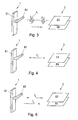
- Fig. 3 to 5 various operating modes of the access control device in cooperation with the electronic key.
- the access control device is designated 1 and the electronic key 2.
- the access control device 1 comprises a transmitting / receiving device 3 with a capacitive data transmission module 4, which transmits data via a capacitive coupling.
- the capacitive data transmission module 4 comprises a coupling capacitor, for example in the form of a capacitor with at least one coupling electrode.
- the data obtained by the transceiver 3 via a capacitive coupling with the key 2 are supplied to processing means in the form of a microcontroller 5 in which the data is processed.
- an evaluation circuit 6 is realized, with which it is determined whether the identification data received from the key 2 results in an access authorization. If the access authorization is checked positively, the microcontroller 5 activates a release element 7, so that a locking member of a locking device, not shown, is released.
- a bidirectional transmission of data between the key 2 and the access control device 1 takes place.
- a bidirectional connection is, for example, for the wake-up function according to the invention, for the exchange of authentication data when establishing a secure connection between the key 2 and the access control device 1 and for the Exchange of status data and test data od.
- the data provided for the transmission from the access control device 1 to the key 2, such as the wake-up signal, are generated and processed in the microcontroller 5 and fed to the transceiver 3.
- a circuit formed in the transmitting / receiving device 3 is responsible for generating a carrier frequency with which the signals are transmitted. Also, the signal strength can be adjusted, with the said circuit in principle may also be provided in the microcontroller 5.
- the circuit is adapted such that the transmitting / receiving device 3 transmits a wake-up signal to the electronic key 2 via a first carrier frequency and that it transmits the data required for carrying out an authentication and / or identification protocol for determining the access authorization via a second carrier frequency ,
- the electronic key 2 also has processing means in the form of a microcontroller 8 and a transmitting / receiving device 9 connected to the microcontroller 8 with a capacitive data transmission module 10.
- the microcontroller comprises a memory 11 for identification data.
- the electronic key 2 has a receiving circuit 12, which is simple in construction and therefore consumes very little power.
- This receiving circuit 12 is either permanently in the ready-to-receive state or switches periodically between a ready-to-receive and a non-ready-to-receive state back and forth.
- the receiving circuit 12 cooperates with a wake-up circuit 13 which, upon receipt of a wake-up signal by the receiving circuit 12, causes the remaining components of the key 2 to be woken up, i. be switched to the operating mode.
- Fig. 2 shows the sequence of a data transfer.
- the fitting initially sends a wake-up signal to wake up the identification medium, ie to switch to the operating mode and to determine whether the identification medium is in the vicinity and is ready for operation.
- the identification medium As soon as the identification medium detects this signal successfully, it sends an acknowledge signal (ACK) back to the fitting.
- ACK acknowledge signal
- fitting identification medium The fitting sends an authentication command to the identification medium ⁇ 1 byte ⁇
- the identification medium generates an 8-byte random number (RndNrI), encrypts it with its key SI and sends it to the fitting.
- SI (RndNrI) 8 bytes
- the fitting decrypts the received 8-byte data with its key (SB) and also generates another 8-byte random number (RndNrB).
- the data RndNrI and RndNrB are encrypted and sent to the ID medium ⁇ SB (RndNrI + RndNrB) 16 bytes ⁇
- the identification medium decrypts all received bytes and controls RndNrI. If these data have changed, SI and SB are different and the identification medium sends an error message for fitting.
- both the fitting and the identification medium have successfully recognized that the respective call partner is valid. Incomplete data, too long waiting time for the response and invalid data immediately lead to a communication abort.
- an 8-byte session key can be generated on both sides. These are generated via a defined calculation algorithm from RndNrI and RndNrB. By using the generated random numbers it is ensured that with each authentication another key is used, which excludes replay attacks and hack attempts to calculate the secret keys SI and SB very elaborately designed.
- the session key is used to encrypt data in encrypted form (see Fig. 2 "Session"). These are necessary to read or write information such as battery status, keys, etc. and can be expanded as required.
- a session is terminated by an end-of-session signal (EOS). A disconnect, too long computation times, and too many retries will automatically result in termination of the session. After a termination of the session, as well as an EOS signal as well as an error, the session key must be recreated.
- EOS end-of-session signal
- the access control device 1 is in each case integrated in a fitting together with a pusher, wherein the integrated capacitive Data transmission module comprises a first coupling electrode E1 and a second coupling electrode E2.
- the first coupling electrode E1 is arranged on or in the fitting plate or is formed by this.
- the second coupling electrode E2 is arranged on or in the pusher or is formed by this.
- the electronic key 2 is designed as a portable identification medium, and has a capacitive data transmission module with a third coupling electrode E3 and a fourth coupling electrode E4.
- the two coupling electrodes E3 and E4 are plate-shaped and arranged parallel to each other.
- Fig. 3 an operating mode is shown in which the access control device emits a pulsed wake-up signal via a capacitive coupling with the ID medium, wherein each wake-up pulse comprises a plurality of preferably unmodulated oscillations on the carrier frequency f1.
- Fig. 4 an operating mode is shown in which the access control device and the identification medium communicate with each other via a carrier frequency f2 to perform an authentication and / or identification protocol.
- Fig. 5 an operating mode is shown in which the access control device and the identification medium as in Fig. 4 communicate with each other via a carrier frequency f2, but the access control device simultaneously emits a busy signal over a carrier frequency f3, which signals other ident media in the environment that the access control device is not available for communication.
- the carrier frequencies f1, f2 and f3 may each be in the ranges of 6.765 - 6.795 MHz, 13.55-3 - 13.567 MHz, 26.957 - 27.283 MHz, 40.66 - 40.70 MHz, 433.05 - 434.79 MHz and 902 - 928 MHz, but the carrier frequencies f1, f2 and f3 are in mutually different areas.
- the carrier frequency f1 is in the range of 13.553 to 13.567 MHz
- the carrier frequency f2 is in the range of 26.957 to 27.283 MHz
- the carrier frequency f3 is in the range of 40.66 to 40.70 MHz, for example.
Landscapes
- Engineering & Computer Science (AREA)
- Computer Networks & Wireless Communication (AREA)
- Physics & Mathematics (AREA)
- General Physics & Mathematics (AREA)
- Lock And Its Accessories (AREA)
Abstract
Verfahren zur Zutrittskontrolle insbesondere in Gebäuden, bei dem eine bidirektionale Datenübermittlung zwischen einem elektronischen Schlüssel und einer Zutrittskontrollvorrichtung stattfindet, wobei die Datenübermittlung das Aussenden eines Aufwecksignals durch die Zutrittskontrollvorrichtung umfasst, um den elektronischen Schlüssel aus einem Schlafmodus aufzuwecken, wobei die Übermittlung des Aufwecksignals über eine kapazitive Kopplung erfolgt, wobei die Datenübermittlung weiters ein Authentifizierungs- und/oder Identifizierungsprotokoll zur Feststellung der Zutrittsberechtigung des elektronischen Schlüssels umfasst, wobei das Aussenden des Aufwecksignals über eine erste Trägerfrequenz und die Durchführung des Authentifizierungs- und/oder Identifizierungsprotokolls über eine zweite Trägerfrequenz erfolgt.A method of access control, especially in buildings, in which bi-directional data transmission between an electronic key and an access control device takes place, the data transmission comprising the transmission of a wake-up signal by the access control device to wake the electronic key from a sleep mode, the transmission of the wake-up signal via a capacitive Coupling takes place, wherein the data transmission further includes an authentication and / or identification protocol for determining the access authorization of the electronic key, wherein the transmission of the wake-up signal via a first carrier frequency and the implementation of the authentication and / or identification protocol via a second carrier frequency.
Description
Die Erfindung betrifft ein Verfahren zur Zutrittskontrolle insbesondere in Gebäuden, bei dem eine bidirektionale Datenübermittlung zwischen einem elektronischen Schlüssel und einer Zutrittskontrollvorrichtung stattfindet, wobei die Datenübermittlung das Aussenden eines Aufwecksignals durch die Zutrittskontrollvorrichtung und das Empfangen des Aufwecksignals in einer Empfangsschaltung des elektronischen Schlüssels umfasst, um den elektronischen Schlüssel aus einem Schlafmodus aufzuwecken und in einen Betriebsmodus zu schalten, wobei die Übermittlung des Aufwecksignals über eine kapazitive Kopplung zwischen dem elektronischen Schlüssel und der Zutrittskontrollvorrichtung erfolgt, wobei die Datenübermittlung nach dem Umschalten in den Betriebsmodus weiters ein Authentifizierungs- und/oder Identifizierungsprotokoll zur Feststellung der Zutrittsberechtigung des elektronischen Schlüssels umfasst, wobei in Abhängigkeit von der festgestellten Zutrittsberechtigung der Zutritt freigeben oder gesperrt wird.The invention relates to a method for access control, in particular in buildings, in which a bidirectional data transmission between an electronic key and an access control device takes place, wherein the data transmission comprises sending a wake-up signal by the access control device and receiving the wake-up signal in a receiving circuit of the electronic key to the waking up an electronic key from a sleep mode and switching to an operating mode, wherein the transmission of the wake-up signal via a capacitive coupling between the electronic key and the access control device, wherein the data transmission after switching to the operating mode further an authentication and / or identification protocol for detection the access authorization of the electronic key includes, depending on the detected access authorization of access ben or is locked.
Die Erfindung betrifft weiters eine Vorrichtung zur Durchführung dieses Verfahrens nach dem Oberbegriff des Anspruchs 12.The invention further relates to an apparatus for carrying out this method according to the preamble of
Ein Verfahren und eine Vorrichtungen dieser Art sind aus der
Unter elektronischen Schlüsseln werden nachfolgend unterschiedliche Ausbildungen von Identmedien verstanden, die einen elektronischen Code bzw. Identifikationsdaten gespeichert haben, z.B. in der Form von Karten, Schlüsselanhängern und Kombinationen aus mechanischen und elektronischen Schlüsseln.Electronic keys are understood to mean different embodiments of ident media that have stored an electronic code or identification data, for example in the form of cards, key fobs and combinations of mechanical and electronic keys.
Der elektronische Schlüssel und ggf. die Zutrittskontrollvorrichtung benötigen zur Stromversorgung einen Energiespeicher, insbesondere eine Batterie. Damit die batteriebetriebenen Komponenten bis zum Batteriewechsel eine möglichst lange Betriebsdauer haben, ist man bestrebt, den Energieverbrauch zu minimieren.The electronic key and possibly the access control device require an energy storage, in particular a battery for power supply. To ensure that the battery-operated components have the longest possible service life until the battery is replaced, efforts are made to minimize energy consumption.
Um Energie zu sparen, verfügen verschiedene Geräte über eine Funktion zur automatischen Teilabschaltung bei Inaktivität. Eine solche Funktion wird auch Bereitschaftsbetrieb, Standby-Betrieb oder Schlafmodus genannt. In diesem Zustand eines technischen Gerätes ist dessen Nutzfunktion zwar temporär deaktiviert, aber jederzeit und ohne Vorbereitungen oder längere Wartezeiten wieder aktivierbar. Damit ersetzt der Schlafmodus nicht das vollständige Ausschalten des Geräts, sondern hilft, in der nutzungsfreien Zeit die Leistungsaufnahme des Geräts zu senken.To save energy, various devices have a feature for automatic partial shutdown in case of inactivity. Such a function is also called standby mode, standby mode or sleep mode. In this state of a technical device whose useful function is temporarily deactivated, but at any time and without preparations or longer waiting times can be activated again. Sleep does not replace the device completely, but helps reduce device power consumption during idle time.
Um den Energieverbrauch zu senken und die Batterielebensdauer entsprechend zu erhöhen, wird in der
- Aussenden eines Aufwecksignals durch die Sendeschaltung der Zutrittskontrollvorrichtung, insbesondere wenn sich eine Person der Zutrittskontrollvorrichtung nähert oder diese berührt,
- Empfangen des Aufwecksignals in der Empfangsschaltung des elektronischen Schlüssels,
- Umschalten des elektronischen Schlüssels vom Schlafmodus in den Betriebsmodus.
- Sending a wake-up signal through the transmission circuit of the access control device, in particular when a person approaches or touches the access control device,
- Receiving the wake-up signal in the receiving circuit of the electronic key,
- Switching the electronic key from sleep mode to operating mode.
Es wird bei schließtechnischen Einrichtungen somit eine Stromsparfunktion dadurch realisiert, dass der elektronische Schlüssel sich die meiste Zeit in einem Schlafmodus befindet, in dem lediglich eine Empfangsschaltung betrieben wird, die wenig Strom verbraucht und die dafür verantwortlich ist, den elektronischen Schlüssel in den Betriebsmodus umzuschalten, sobald ein Aufwecksignal einer zugehörigen Zutrittskontrollvorrichtung dadurch empfangen wird, dass sich die den elektronischen Schlüssel tragende Person der Zutrittskontrollvorrichtung nähert oder diese berührt. Eine besonders effiziente Reduzierung des Stromverbrauchs ergibt sich, wie in der
Nachteilig beim Stand der Technik ist jedoch der Umstand, dass der Aufweckprozess selbst auch bei Nutzung eines elektrischen Nahfelds einen Energieverbrauch verursacht, der insbesondere bei oftmaliger Durchführung erheblich sein kann.A disadvantage of the prior art, however, is the fact that the wake-up process itself even when using a electric power field causes energy consumption, which can be considerable, especially in frequent implementation.
Die vorliegende Erfindung zielt daher darauf ab, den Stromverbrauch für den Aufweckprozess zu reduzieren.The present invention therefore aims to reduce the power consumption for the wake-up process.
Zur Lösung dieser Aufgabe sieht die Erfindung bei einem Verfahren der eingangs genannten Art vor, dass das Aussenden des Aufwecksignals über eine erste Trägerfrequenz und die Durchführung des Authentifizierungs- und/oder Identifizierungsprotokolls über eine zweite Trägerfrequenz erfolgt, wobei die erste und die zweite Trägerfrequenz voneinander verschieden sind. Dadurch, dass das Aufwecksignal über eine eigene Trägerfrequenz übermittelt wird, kann die Empfangsschaltung des elektronischen Schlüssels allein anhand der Frequenz des empfangenen Signals feststellen, ob es sich um ein Aufwecksignal einer Zutrittskontrollvorrichtung handelt. Es ist daher nicht zwingend erforderlich, dass eine Demodulierung des erhaltenen Signals erfolgt, um einen Datenstrom zu erhalten, der dann hinsichtlich des Vorliegens einer Aufweckkennung ausgewertet wird. Vielmehr kann das Aufwecksignal als reine Trägerwelle mit der ersten Trägerfrequenz vorliegen.To solve this problem, the invention provides in a method of the type mentioned that the transmission of the wake-up signal via a first carrier frequency and the implementation of the authentication and / or identification protocol via a second carrier frequency, wherein the first and the second carrier frequency from each other are. Characterized in that the wake-up signal is transmitted via its own carrier frequency, the receiving circuit of the electronic key can determine only on the basis of the frequency of the received signal, if it is a wake-up signal of an access control device. It is therefore not absolutely necessary that a demodulation of the received signal takes place in order to obtain a data stream, which is then evaluated for the presence of a wake-up identifier. Rather, the wake-up signal can be present as a pure carrier wave with the first carrier frequency.
Bevorzugt kann vorgesehen sein, dass bei einer Schließanlage mit einer Mehrzahl von Zutrittskontrollvorrichtungen die erste Trägerfrequenz in den einzelnen Zutrittskontrollvorrichtungen untereinander verschieden ist.Preferably, it can be provided that in a locking system with a plurality of access control devices, the first carrier frequency in the individual access control devices is different from each other.
Eine besondere Energieersparnis ergibt sich bevorzugt dadurch, dass die erste Trägerfrequenz niedriger ist als die zweite Trägerfrequenz. Insbesondere beträgt das Verhältnis von zweiter Trägerfrequenz zu erster Trägerfrequenz wenigstens 6:5, bevorzugt wenigstens 4:3, besonders bevorzugt wenigstens 2:1.A particular energy saving results preferably in that the first carrier frequency is lower than the second carrier frequency. In particular, the ratio of the second carrier frequency to the first carrier frequency at least 6: 5, preferably at least 4: 3, more preferably at least 2: 1.
Bevorzugt werden Frequenzen für die erste und die zweite Trägerfrequenz eingesetzt, die keiner behördlichen Einzel-Frequenzzuweisung bzw. Genehmigung bedürfen. Bevorzugt handelt es sich dabei um Trägerfrequenzen in den Frequenzbereichen gemäß ISM (Industrial, Scientific and Medical Band). Es handelt sich dabei insbesondere um die Frequenzbereiche 6,765 - 6,795 MHz, 13,553 - 13,567 MHz, 26,957 - 27,283 MHz, 40,66 - 40,70 MHz, 433,05 - 434,79 MHz und 902 - 928 MHz.Preference is given to using frequencies for the first and the second carrier frequency, which require no official individual frequency allocation or approval. These are preferably carrier frequencies in the frequency ranges according to ISM (Industrial, Scientific and Medical Band). In particular, these are the frequency bands 6.765 - 6.795 MHz, 13.553 - 13.567 MHz, 26.957 - 27.283 MHz, 40.66 - 40.70 MHz, 433.05 - 434.79 MHz and 902 - 928 MHz.
Grundsätzlich beträgt die erste Trägerfrequenz bevorzugt weniger als 1 GHz, weil Bauteile mit einer Ausdehnung, wie sie übelicherweise bei Zutrittskontrollvorrichtungen zum Einsatz kommen (d.h. einige Zentimeter), bei höheren Frequenzen auf Grund der kürzeren Wellenlänge einen Antenneneffekt aufweisen können, wodurch es zur Abstrahlung von elektromagnetischen Wellen kommen würde.In principle, the first carrier frequency is preferably less than 1 GHz, because components with an extent, as conventionally used in access control devices (ie, a few centimeters), may have an antenna effect at higher frequencies due to the shorter wavelength, thereby increasing the emission of electromagnetic energy Waves would come.
Erfindungsgemäß wird für die Datenübermittlung Nahfeldkommunikation verwendet.According to the invention, near field communication is used for data transmission.
Die Umschaltung des elektronischen Schlüssels in den Betriebsmodus kann bevorzugt dann erfolgen, wenn in der Empfangsschaltung ein Aufwecksignal mit einer der ersten Trägerfrequenz entsprechenden Frequenz detektiert wird, sodass keine weitere Auswertung des Aufwecksignals erfolgen muss. Weiters kann bevorzugt so vorgegangen werden, dass die Anzahl der in der Empfangsschaltung des elektronischen Schlüssels empfangenen Schwingungen des die erste Trägerfrequenz aufweisenden Aufwecksignals erfasst wird und die Umschaltung des elektronischen Schlüssels in den Betriebsmodus erfolgt, wenn die Anzahl der detektierten Schwingungen einen definierten Grenzwert überschreitet. Es erfolgt somit ein Aufsummieren der Schwingungen des Aufwecksignals, sodass eine Auswertung erfolgen kann, wie viele Schwingungen in einem bestimmten Zeitintervall empfangen werden. Dies ermöglicht eine Aussage über die Qualität des erhaltenen Signals bzw. der kapazitiven Kopplung ohne dass eine Demodulation erfolgen muss.The switching of the electronic key into the operating mode can preferably take place when a wake-up signal having a frequency corresponding to the first carrier frequency is detected in the receiving circuit, so that no further evaluation of the wake-up signal must take place. Furthermore, it may be preferable to proceed in such a way that the number of vibrations of the wake-up signal having the first carrier frequency received in the receiving circuit of the electronic key is detected and the switching of the electronic key in the operating mode takes place when the number of detected vibrations exceeds a defined limit. There is thus an accumulation of the vibrations of the wake-up signal, so that an evaluation can be made of how many vibrations are received in a certain time interval. This allows a statement about the quality of the received signal or the capacitive coupling without demodulation must be done.
Alternativ oder zusätzlich kann das erhaltene Aufwecksignal aber auch nach anderen Parametern ausgewertet werden, um zu verhindern, dass der elektronische Schlüssel möglicherweise irrtümlich allein auf Grund des Vorhandenseins der ersten Trägerfrequenz aufgeweckt wird. Dazu wird bevorzugt so vorgegangen, dass das Aufwecksignal gepulst ausgesendet wird und die Umschaltung des elektronischen Schlüssels in den Betriebsmodus erfolgt, wenn das Pulsmuster des Aufwecksignals einem vorgegebenen Muster entspricht.Alternatively or additionally, however, the obtained wake-up signal may also be evaluated according to other parameters in order to prevent the electronic key from possibly being woken up erroneously solely on the basis of the presence of the first carrier frequency. For this purpose, the procedure is preferably such that the wake-up signal is transmitted pulsed and the switching of the electronic key is in the operating mode when the pulse pattern of the wake-up signal corresponds to a predetermined pattern.
Alternativ oder zusätzlich kann so vorgegangen werden, dass das Aufwecksignal Frequenz- und/oder Amplitudenmodulationen aufweist. Diese sind somit in das Aufwecksignal eingeprägt und dienen als Erkennungsmerkmale, die vom Schlüssel erkannt werden, damit nicht jedes Signal auf der Aufweckfrequenz des Schlüssels zu einem Aufwecken des Schlüssels führt, sodass der Stromverbrauch des Schlüssels besonders niedrig gehalten werden kann. Insbesondere kann das Aufwecksignal eine auf das Trägerfrequenz aufmodulierte Kennung umfassen, wobei das Aufwecksignal in der Empfangsschaltung demoduliert wird, wobei die Umschaltung des elektronischen Schlüssels in den Betriebsmodus erfolgt, wenn die mit dem Aufwecksignal übermittelte und in der Empfangsschaltung empfangene Kennung einem vorgegebenen Wert entspricht. Durch die Übertragung der Kennung kann gleichzeitig eine Identifizierung der Zutrittskontrollvorrichtung erfolgen.Alternatively or additionally, it is possible to proceed in such a way that the wake-up signal has frequency and / or amplitude modulations. These are thus impressed in the wake-up signal and serve as recognition features that are recognized by the key, so that not every signal on the wake-up frequency of the key leads to a waking of the key, so that the power consumption of the key can be kept very low. In particular, the wake-up signal may comprise an identifier modulated onto the carrier frequency, wherein the wake-up signal is demodulated in the receiving circuit, the switching of the electronic key to the operating mode when the identifier transmitted with the wake-up signal and received in the receiving circuit corresponds to a predetermined value. By the transmission of the identifier can be done at the same time an identification of the access control device.
Die Empfangsschaltung des elektronischen Schlüssels muss grundsätzlich nicht ständig empfangsbereit sein. Vielmehr kann die Empfangsschaltung bevorzugt so betrieben werden, dass sie während des Schlafmodus periodisch zwischen einem Empfangsmodus, in dem sie empfangsbereit ist, und einem Ruhemodus, in dem sie nicht empfangsbereit ist, hin- und hergeschaltet wird, wodurch der Stromverbrauch weiter reduziert werden kann. Bei der Empfangsschaltung kann es sich um die Sende-/Empfangseinrichtung des elektronischen Schlüssels handeln, über welche die Datenübertragung im Betriebsmodus erfolgt, oder es kann sich um eine gesonderte, besonders einfach gebaute und deshalb stromsparende Schaltung handeln, die ausschließlich dem Empfang des Aufwecksignals dient.The receiving circuit of the electronic key generally does not have to be constantly ready to receive. Rather, the receiving circuit may be preferably operated to periodically switch between a receive mode in which it is ready to receive and a sleep mode in which it is not ready to receive during the sleep mode, whereby the power consumption can be further reduced. The receiving circuit may be the transmitting / receiving device of the electronic key, via which the data transmission takes place in the operating mode, or it may be a separate, particularly simple and therefore power-saving circuit, which serves exclusively to receive the wake-up signal.
Bevorzugt wird der Zutrittskontrollvorrichtung der erfolgreiche Aufweckvorgang dadurch mitgeteilt, dass der elektronische Schlüssel nach Erreichen des Betriebsmodus eine Bestätigungsnachricht an die Zutrittskontrollvorrichtung übermittelt.Preferably, the access control device is notified of the successful wake-up process in that the electronic key transmits an acknowledgment message to the access control device after reaching the operating mode.
Um auch auf der Seite der Zutrittskontrollvorrichtung Strom zu sparen, wird bevorzugt so vorgegangen, dass das Aufwecksignal periodisch ausgesendet wird. Das Aufwecksignal wird hierbei bevorzugt mehrmals pro Sekunde ausgesendet, damit der Aufweckvorgang keine große Verzögerung des Zutrittsvorganges mit sich bringt.In order to save power also on the side of the access control device, it is preferable to proceed so that the wake-up signal is transmitted periodically. The wake-up signal is preferably transmitted several times per second so that the wake-up does not entail a great delay of the access process.
Sobald der elektronische Schlüssel in den Betriebsmodus gewechselt ist, erfolgt die weitere Datenkommunikation über die zweite Trägerfrequenz, wobei in der Regel ein vorgegebenes Authentifizierungs- und/oder Identifizierungsprotokoll durchgeführt wird, um die Gültigkeit der Kommunikationspartner und die Zutrittsberechtigung des Schlüssels zu überprüfen. Die Authentifizierung kann eine "Challenge-Response"-Authentifizierung umfassen. Grundsätzlich kann die für das Authentifizierungs- und/oder Identifizierungsprotokoll erforderliche bidirektionale Datenübertragung über beliebige Nah- oder Fernfeldkommunikationswege erfolgen. Beispielsweise können die Daten über ein elektromagnetisches Feld, also per Funk übermittelt werden. Bevorzugt ist jedoch vorgesehen, dass die Durchführung des Authentifizierungs- und/oder Identifizierungsprotokolls zumindest teilweise über eine kapazitive Kopplung zwischen dem elektronischen Schlüssel und der Zutrittskontrollvorrichtung erfolgt, d.h. also über ein im Wesentliches elektrisches Feld.As soon as the electronic key has changed into the operating mode, the further data communication takes place via the second carrier frequency, whereby a predetermined authentication and / or identification protocol is usually carried out in order to check the validity of the communication partners and the access authorization of the key. The authentication may include a challenge-response authentication. In principle, the bidirectional data transmission required for the authentication and / or identification protocol can take place via any local or far-field communication paths. For example, the data can be transmitted via an electromagnetic field, ie by radio. Preferably, however, it is provided that the implementation of the authentication and / or identification protocol takes place at least partially via a capacitive coupling between the electronic key and the access control device, i. that is, over an essentially electric field.
Die der Erfindung zugrunde liegende Idee der Verwendung von unterschiedlichen Trägerfrequenzen kann in besonders vorteilhafter Weise auch für die Arbitrierung der Kommunikation im Falle von mehreren Zutrittskontrollvorrichtungen im Empfangsbereich eines elektronischen Schlüssels und/oder im Falle von mehreren elektronischen Schlüsseln im Empfangsbereich einer Zutrittskontrollvorrichtung genutzt werden. Zugriffskonflikte können dabei besonders vorteilhaft dadurch gelöst werden, dass die Zutrittskontrollvorrichtung während der Datenkommunikation mit dem elektronischen Schlüssel ein Besetztsignal über eine dritte Trägerfrequenz aussendet, wobei die dritte Trägerfrequenz von der ersten und der zweiten Trägerfrequenz verschieden ist. Bevorzugt übermittelt die Empfangsschaltung des elektronischen Schlüssels bei Detektieren eines Besetztsignals keine weiteren Signale an die entsprechende Zutrittskontrollvorrichtung. Die Zutrittskontrollvorrichtung arbeitet somit zum Beispiel gleichzeitig auf der zweiten Trägerfrequenz und auf der dritten Trägerfrequenz, um all den anderen Schlüsseln im Empfangsbereich zu signalisieren, dass diese für eine zusätzliche Kommunikation gegenwärtig nicht zur Verfügung steht. Auf diese Weise wird die laufende Kommunikation auf der zweiten Trägerfrequenz nicht durch Kommunikationsversuche anderer Schlüssel gestört.The idea underlying the invention of the use of different carrier frequencies can be used in a particularly advantageous manner for the arbitration of communication in the case of multiple access control devices in the reception area of an electronic key and / or in the case of multiple electronic keys in the reception area of an access control device. Access conflicts can be solved particularly advantageous in that the access control device emits a busy signal via a third carrier frequency during data communication with the electronic key, wherein the third carrier frequency of the first and the second carrier frequency is different. The receiving circuit of the electronic key preferably does not transmit any further signals to the corresponding access control device upon detection of a busy signal. The access control device thus operates, for example, simultaneously on the second carrier frequency and on the third carrier frequency to signal to all the other keys in the receiving area that it is not currently available for additional communication. In this way, the current communication on the second carrier frequency is not disturbed by communication attempts of other keys.
Gemäß einem weiteren Aspekt der vorliegenden Erfindung wird eine Vorrichtung vorgeschlagen, umfassend eine Zutrittskontrollvorrichtung und einen elektronischen Schlüssel, die jeweils eine Sende-/Empfangseinrichtung aufweisen, um eine bidirektionale Datenübermittlung zwischen dem elektronischen Schlüssel und der Zutrittskontrollvorrichtung zu ermöglichen, wobei der elektronische Schlüssel einen Speicher für Identifikationsdaten aufweist, der mit der Sende-/Empfangseinrichtung des Schlüssels zur Durchführung eines Authentifizierungs- und/oder Identifizierungsprotokolls zusammenwirkt, wobei die Zutrittskontrollvorrichtung eine Auswerteschaltung zur Feststellung der Zutrittsberechtigung auf Grund des Authentifizierungs- und/oder Identifizierungsprotokolls aufweist, um den Zutritt wahlweise freizugeben oder zu sperren, wobei die Sende-/Empfangseinrichtung der Zutrittskontrollvorrichtung zum Aussenden eines Aufwecksignals ausgebildet ist und im elektronischen Schlüssel eine Empfangsschaltung zum Empfangen des Aufwecksignals während eines Schlafmodus vorgesehen ist, wobei die Empfangsschaltung mit einer Aufweckschaltung zusammenwirkt, um den elektronischen Schlüssel vom Schlafmodus in einen Betriebsmodus umzuschalten, wenn die Empfangsschaltung das Aufwecksignal empfängt, wobei die Sende-/Empfangseinrichtung des elektronischen Schlüssels und der Zutrittskontrollvorrichtung jeweils ein wenigstens eine kapazitive Koppelfläche aufweisendes kapazitives Datenübertragungsmodul aufweist, wobei die Übermittlung des Aufwecksignals über eine kapazitive Kopplung zwischen dem elektronischen Schlüssel und der Zutrittskontrollvorrichtung erfolgt. Die Erfindung sieht dabei vor, dass die Sende-/Empfangseinrichtung der Zutrittskontrollvorrichtung ausgebildet ist, um das Aufwecksignal über eine erste Trägerfrequenz auszusenden und um das Authentifizierungs- und/oder Identifizierungsprotokoll über eine zweite Trägerfrequenz durchzuführen, wobei die erste und die zweite Trägerfrequenz voneinander verschieden sind.According to a further aspect of the present invention, a device is proposed, comprising an access control device and an electronic key, each having a transmitting / receiving device to allow bidirectional data transmission between the electronic key and the access control device, wherein the electronic key memory for Identification data, which cooperates with the transmitting / receiving device of the key for performing an authentication and / or identification protocol, wherein the access control device comprises an evaluation circuit for determining the access authorization on the basis of the authentication and / or identification protocol to selectively enable the access or to lock, wherein the transmitting / receiving device of the access control device is designed to send a wake-up signal and in the electronic key a Empfan is provided for receiving the wake-up signal during a sleep mode, wherein the receiving circuit cooperates with a wake-up circuit to switch the electronic key from the sleep mode to an operating mode when the receiving circuit receives the wake-up signal, the electronic key transmitter and the access control device each having a capacitive data transmission module having at least one capacitive coupling surface the transmission of the wake-up signal via a capacitive coupling between the electronic key and the access control device takes place. The invention provides that the transmitting / receiving device of the access control device is designed to transmit the wake-up signal over a first carrier frequency and to perform the authentication and / or identification protocol over a second carrier frequency, wherein the first and the second carrier frequency are different from each other ,
Bevorzugte Weiterbildungen der erfindungsgemäßen Vorrichtung sind in den Unteransprüchen definiert.Preferred developments of the device according to the invention are defined in the subclaims.
Bevorzugt kann vorgesehen sein, dass die erste Trägerfrequenz niedriger ist als die zweite Trägerfrequenz.It can preferably be provided that the first carrier frequency is lower than the second carrier frequency.
Bevorzugt kann vorgesehen sein, dass das Verhältnis von zweiter Trägerfrequenz zu erster Trägerfrequenz wenigstens 6:5, bevorzugt wenigstens 4:3, besonders bevorzugt wenigstens 2:1 beträgt.It can preferably be provided that the ratio of the second carrier frequency to the first carrier frequency is at least 6: 5, preferably at least 4: 3, particularly preferably at least 2: 1.
Bevorzugt kann vorgesehen sein, dass die erste Trägerfrequenz und ggf. die zweite Trägerfrequenz in den Frequenzbereichen gemäß ISM (Industrial, Scientific and Medical Band) liegt, insbesondere in den Frequenzbereichen 6,765 - 6,795 MHz, 13, 553 - 13,567 MHz, 26,957 - 27,283 MHz, 40, 66 - 40, 70 MHz, 433,05 - 434,79 MHz und 902 - 928 MHz.It can preferably be provided that the first carrier frequency and possibly the second carrier frequency are in the frequency ranges according to ISM (Industrial, Scientific and Medical Band), in particular in the frequency ranges 6.765-6.795 MHz, 13, 553 - 13.567 MHz, 26.957 - 27.283 MHz, 40, 66 - 40, 70 MHz, 433.05 - 434.79 MHz and 902 - 928 MHz.
Bevorzugt kann vorgesehen sein, dass die Aufweckschaltung ausgebildet ist, um den elektronischen Schlüssel in den Betriebsmodus umzuschalten, wenn in der Empfangsschaltung ein Aufwecksignal mit einer der ersten Trägerfrequenz entsprechenden Frequenz detektiert wird.Preferably, it can be provided that the wake-up circuit is designed to switch the electronic key into the operating mode when a wake-up signal having a frequency corresponding to the first carrier frequency is detected in the receiving circuit.
Bevorzugt kann vorgesehen sein, dass die Aufweckschaltung ausgebildet ist, um die Anzahl der in der Empfangsschaltung des elektronischen Schlüssels empfangenen Schwingungen des die ersten Trägerfrequenz aufweisenden Aufwecksignals zu erfassen und den elektronischen Schlüssel in den Betriebsmodus umzuschalten, wenn die Anzahl der detektierten Schwingungen einen definierten Grenzwert überschreitet.Preferably, it can be provided that the wake-up circuit is designed to detect the number of received in the receiving circuit of the electronic key vibrations of the first carrier frequency having wake-up signal and to switch the electronic key in the operating mode when the number of detected vibrations exceeds a defined limit ,
Bevorzugt kann vorgesehen sein, dass die Sende-/Empfangseinrichtung der Zutrittskontrollvorrichtung ausgebildet ist, um das Aufwecksignals gepulst auszusenden und die Aufweckschaltung bevorzugt ausgebildet ist, um den elektronischen Schlüssel in den Betriebsmodus umzuschalten, wenn das Pulsmuster des Aufwecksignals einem vorgegebenen Muster entspricht.It can preferably be provided that the transmitting / receiving device of the access control device is designed to emit the wake-up signal pulsed and the wake-up circuit is preferably designed to switch the electronic key in the operating mode when the pulse pattern of the wake-up signal corresponds to a predetermined pattern.
Bevorzugt kann vorgesehen sein, dass die Sende-/Empfangseinrichtung der Zutrittskontrollvorrichtung einen Modulator umfasst, um eine Kennung auf die Trägerfrequenz des Aufwecksignals aufzumodulieren, und dass die Empfangsschaltung einen Demodulator zum Demodulieren des Aufwecksignals umfasst, wobei die Umschaltung des elektronischen Schlüssels in den Betriebsmodus erfolgt, wenn die mit dem Aufwecksignal übermittelte und in der Empfangsschaltung empfangene Kennung einem vorgegebenen Wert entspricht.Preferably, it can be provided that the transmitting / receiving device of the access control device comprises a modulator to modulate an identifier to the carrier frequency of the wake-up signal, and that the receiving circuit comprises a demodulator for demodulating the wake-up signal, wherein the switching of the electronic key is in the operating mode, if the transmitted with the wake-up signal and in the Receive circuit received identifier corresponds to a predetermined value.
Bevorzugt kann vorgesehen sein, dass das kapazitive Datenübertragungsmodul des elektronischen Schlüssels und der Zutrittskontrollvorrichtung jeweils ausgebildet sind, um das Authentifizierungs- und/oder Identifizierungsprotokoll zumindest teilweise über eine kapazitive Kopplung zwischen dem elektronischen Schlüssel und der Zutrittskontrollvorrichtung durchzuführen.Preferably, it may be provided that the capacitive data transmission module of the electronic key and the access control device are each designed to perform the authentication and / or identification protocol at least partially via a capacitive coupling between the electronic key and the access control device.
Bevorzugt kann vorgesehen sein, dass die Empfangsschaltung während des Schlafmodus periodisch zwischen einem Empfangsmodus, in dem sie empfangsbereit ist, und einem Ruhemodus, in dem sie nicht empfangsbereit ist, hin- und hergeschalten wird.Preferably, it can be provided that the receiving circuit during the sleep mode periodically between a receive mode in which it is ready to receive, and a sleep mode in which it is not ready to receive, switched back and forth.
Bevorzugt kann vorgesehen sein, dass die Zutrittskontrollvorrichtung ausgebildet ist, um während der Datenkommunikation mit dem elektronischen Schlüssel ein Besetztsignal über eine dritte Trägerfrequenz auszusenden, wobei die dritte Trägerfrequenz von der ersten und der zweiten Trägerfrequenz verschieden ist.Preferably, it may be provided that the access control device is designed to emit a busy signal via a third carrier frequency during the data communication with the electronic key, the third carrier frequency being different from the first and the second carrier frequency.
Bevorzugt kann vorgesehen sein, dass die Empfangsschaltung des elektronischen Schlüssels ausgebildet ist, um bei Detektieren eines Besetztsignals keine weiteren Signale an die entsprechende Zutrittskontrollvorrichtung zu übermitteln.It can preferably be provided that the receiving circuit of the electronic key is designed to transmit no further signals to the corresponding access control device upon detection of a busy signal.
Bevorzugt kann vorgesehen sein, dass die Empfangsschaltung des elektronischen Schlüssels von der Sende-/Empfangseinrichtung des elektronischen Schlüssels gesondert ausgebildet ist.Preferably, it can be provided that the receiving circuit of the electronic key is formed separately from the transmitting / receiving device of the electronic key.
Bevorzugt kann vorgesehen sein, dass das kapazitive Datenübertragungsmodul der Zutrittskontrollvorrichtung wenigstens zwei Koppelelektroden aufweist, die mit der Sende-/Empfangseinrichtung der Zutrittskontrollvorrichtung derart zusammenwirken, dass das Aufwecksignal, die für das Authentifizierungs- und/oder Identifizierungsprotokolls erforderlichen Daten und ggf. das Besetztsignal über die zwei Koppelelektroden ausgesendet werden.Preferably, it can be provided that the capacitive data transmission module of the access control device has at least two coupling electrodes which cooperate with the transmitting / receiving device of the access control device such that the wake-up signal, the data required for the authentication and / or identification protocol and possibly the busy signal on the two coupling electrodes are emitted.
Bevorzugt kann vorgesehen sein, dass der elektronische Schlüssel Verarbeitungsmittel aufweist, die mit der Sende-/Empfangseinrichtung zusammenwirken und so eingerichtet sind, dass die Sende-/Empfangseinrichtung nach Erreichen des Betriebsmodus eine Bestätigungsnachricht an die Zutrittskontrollvorrichtung übermittelt. Die Verarbeitungsmittel können beispielsweise von einem aus dem Stand der Technik bekannten Mikrokontroller gebildet sein.It can preferably be provided that the electronic key has processing means which cooperate with the transmitting / receiving device and are set up such that the transmitting / receiving device transmits an acknowledgment message to the access control device after reaching the operating mode. The processing means may for example be formed by a microcontroller known from the prior art.
Bevorzugt kann vorgesehen sein, dass die Zutrittskontrollvorrichtung Verarbeitungsmittel aufweist, die mit der Sende-/Empfangsschaltung zusammenwirken und so eingerichtet sind, dass das Aufwecksignal periodisch ausgesendet wird.Preferably, it can be provided that the access control device comprises processing means which cooperate with the transmitting / receiving circuit and are arranged so that the wake-up signal is transmitted periodically.
Bevorzugt kann vorgesehen sein, dass die Verarbeitungsmittel so eingerichtet sind, dass das Aufwecksignals Frequenz- und/oder Amplitudenmodulationen aufweist. Diese sind somit in das Aufwecksignal eingeprägt und dienen als Erkennungsmerkmale, die vom Schlüssel erkannt werden, damit nicht jedes Signal auf der Aufweckfrequenz des Schlüssels zu einem Aufwecken des Schlüssels führt, sodass der Stromverbrauch des Schlüssels besonders niedrig gehalten werden kann.It can preferably be provided that the processing means are set up such that the wake-up signal has frequency and / or amplitude modulations. These are thus impressed in the wake-up signal and serve as recognition features that are recognized by the key, so that not every signal on the wake-up frequency of the key leads to a wake-up of the key, so that the Power consumption of the key can be kept very low.
Grundsätzlich kann vorgesehen sein, dass die Sende-/Empfangseinrichtung des elektronischen Schlüssels und der Zutrittskontrollvorrichtung jeweils ein Funkübertragungsmodul und ein kapazitiv arbeitendes Datenübertragungsmodul und eine Steuerschaltung aufweisen, die eingerichtet ist, um Daten im Zuge des Authentifizierungs- und/oder Identifizierungsprotokolls in Abhängigkeit von Steuerinformationen entweder über das Funkübertragungsmodul oder über das kapazitive Datenübertragungsmodul oder über beide Module zu empfangen oder zu senden.In principle it can be provided that the transmitting / receiving device of the electronic key and the access control device each have a radio transmission module and a capacitive data transmission module and a control circuit which is adapted to data in the course of the authentication and / or identification protocol depending on control information either via the radio transmission module or via the capacitive data transmission module or via both modules to receive or to send.
Bevorzugt werden aber sowohl das Aufwecksignal als auch die im Rahmen des Authentifizierungs- und/oder Identifizierungsprotokolls ausgetauschten Daten über eine kapazitive Kopplung übermittelt. In diesem Fall ist bevorzugt vorgesehen, dass das kapazitive Datenübertragungsmodul der Zutrittskontrollvorrichtung wenigstens zwei Koppelelektroden aufweist, die mit der Sende-/Empfangseinrichtung der Zutrittskontrollvorrichtung derart zusammenwirken, dass das Aufwecksignal, die für das Authentifizierungs- und/oder Identifizierungsprotokolls erforderlichen Daten und ggf. das Besetztsignal über die zwei Koppelelektroden ausgesendet werden. Es werden somit die gleichen Elektroden für die Signalaussendung über alle Trägerfrequenzen verwendet.Preferably, however, both the wake-up signal and the data exchanged in the context of the authentication and / or identification protocol are transmitted via a capacitive coupling. In this case, it is preferably provided that the capacitive data transmission module of the access control device has at least two coupling electrodes which interact with the transmitting / receiving device of the access control device such that the wake-up signal, the data required for the authentication and / or identification protocol and possibly the busy signal be sent via the two coupling electrodes. Thus, the same electrodes are used for the signal transmission over all carrier frequencies.
Eine vorteilhafte Ausbildung ergibt sich, wenn wenigstens eine Elektrode der Koppelkapazität der Zutrittskontrollvorrichtung in eine Betätigungseinrichtung der Zutrittskontrollvorrichtung, insbesondere in einen Knauf oder einen Drücker integriert ist oder diesen ausbildet. Bevorzugt ist eine weitere Elektrode der Koppelkapazität der Zutrittskontrollvorrichtung in einen Beschlag der Zutrittskontrollvorrichtung integriert. Insbesondere kann das Beschlagsschild als die eine Elektrode und der zugehörige Drücker oder Knauf als die zweite Elektrode der Koppelkapazität ausgebildet sein.An advantageous embodiment results if at least one electrode of the coupling capacity of the access control device is integrated in an actuating device of the access control device, in particular in a knob or a pusher or forms this. Preferably, a further electrode of the coupling capacity of the access control device is integrated in a fitting of the access control device. In particular, the fitting plate can be designed as the one electrode and the associated pusher or pommel as the second electrode of the coupling capacitance.
Die zwei Koppelelektroden des elektronischen Schlüssels sind bevorzugt parallel zueinander angeordnet. Dadurch ergibt sich bei der dem Körper des Benutzers zugewandten Elektrode eine besonders gute kapazitive Kopplung mit dem Körper, wobei die dem Körper abgewandte Elektrode gut in die Umgebung koppelt.The two coupling electrodes of the electronic key are preferably arranged parallel to one another. This results in the body of the user facing electrode a particularly good capacitive coupling with the body, wherein the body facing away from the electrode coupled well into the environment.
Die Aufweckschaltung des elektronischen Schlüssels kann bevorzugt als im Wesentlichen analoger Schaltkreis ausgebildet sein. Es ist aber auch eine Ausbildung als digitaler Schaltkreis oder als gemischter Schaltkreis mit analogen und digitalen Bauelementen möglich.The wake-up circuit of the electronic key may preferably be designed as a substantially analog circuit. But it is also a training as a digital circuit or as a mixed circuit with analog and digital components possible.
Die Erfindung wird nachfolgend anhand von in der Zeichnung dargestellten Ausführungsbeispielen näher erläutert. In dieser zeigen
In
Im Zuge eines Zutrittswunsches erfolgt eine bidirektionale Übertragung von Daten zwischen dem Schlüssel 2 und der Zutrittskontrollvorrichtung 1. Eine bidirektionale Verbindung ist beispielsweise für die erfindungsgemäße Aufweckfunktion, für den Austausch von Authentifizierungsdaten beim Aufbau einer sicheren Verbindung zwischen dem Schlüssel 2 und der Zutrittskontrollvorrichtung 1 und für den Austausch von Statusdaten und Prüfdaten od. dgl. erforderlich. Die für die Versendung von der Zutrittskontrollvorrichtung 1 an den Schlüssel 2 vorgesehenen Daten, wie z.B. das Aufwecksignal, werden in dem Mikrokontroller 5 generiert und aufbereitet und der Sende-/Empfangseinrichtung 3 zugeführt. Eine in der Sende-/Empfangseinrichtung 3 ausgebildete Schaltung ist dabei dafür verantwortlich, eine Trägerfrequenz zu generieren, mit welcher die Signale ausgesendet werden. Auch die Signalstärke kann angepasst werden, wobei die genannte Schaltung grundsätzlich auch im Mikrokontroller 5 vorgesehen sein kann. Die Schaltung ist derart angepasst, dass die Sende-/Empfangseinrichtung 3 ein Aufwecksignal über eine erste Trägerfrequenz an den elektronischen Schlüssel 2 übermittelt und dass sie die für die Durchführung eines Authentifizierungs- und/oder Identifizierungsprotokolls zur Feststellung der Zutrittsberechtigung erforderlichen Daten über eine zweite Trägerfrequenz übermittelt.In the course of an access request, a bidirectional transmission of data between the key 2 and the
Der elektronische Schlüssel 2 weist ebenfalls Verarbeitungsmittel in der Form eines Mikrokontrollers 8 und eine mit dem Mikrokontroller 8 verbundene Sende-/Empfangseinrichtung 9 mit einem kapazitiven Datenübertragungsmodul 10 auf. Der Mikrokontroller umfasst einen Speicher 11 für Identifikationsdaten.The
Zur Realisierung der erfindungsgemäßen Aufweckfunktion weist der elektronische Schlüssel 2 eine Empfangsschaltung 12 auf, die einfach aufgebaut ist und daher sehr wenig Strom verbraucht. Diese Empfangsschaltung 12 ist entweder dauerhaft im empfangsbereiten Zustand oder wechselt periodisch zwischen einem empfangsbereiten und einem nicht-empfangsbereiten Zustand hin und her. Die Empfangsschaltung 12 wirkt mit einer Aufweckschaltung 13 zusammen, die bei Empfang eines Aufwecksignals durch die Empfangsschaltung 12 dafür sorgt, dass die restlichen Komponenten des Schlüssels 2 aufgeweckt, d.h. in den Betriebsmodus umgeschaltet werden.For realizing the wake-up function according to the invention, the
Im Zuge eines Zutrittswunsches kann die im nachfolgenden Beispiel (
Am Ende hat sowohl der Beschlag als auch das Identmedium erfolgreich erkannt, dass der jeweilige Gesprächspartner gültig ist. Unvollständige Daten, eine zu lange Wartezeit auf die Response und ungültige Daten führen sofort zu einem Kommunikationsabbruch.At the end, both the fitting and the identification medium have successfully recognized that the respective call partner is valid. Incomplete data, too long waiting time for the response and invalid data immediately lead to a communication abort.
In weiterer Folge kann ein 8 Byte Session-Schlüssel (SK) auf beiden Seiten generiert werden. Diese werden über einen festgelegten Berechnungsalgorithmus aus RndNrI und RndNrB generiert. Durch die Verwendung der generierten Zufallszahlen ist sichergestellt, dass bei jeder Authentifizierung ein anderer Schlüssel verwendet wird, welches Replay-Attacken ausschließt und Hack-Versuche die geheimen Schlüssel SI und SB zu errechnen sehr aufwendig gestaltet. Der Session-Schlüssel dient dazu, um in weiterer Folge Daten verschlüsselt auszutauschen (siehe
In den
In
In
In
Die Trägerfrequenzen f1, f2 und f3 können jeweils in den Bereichen 6,765 - 6,795 MHz, 13,55-3 - 13,567 MHz, 26,957 - 27,283 MHz, 40,66 - 40,70 MHz, 433,05 - 434,79 MHz und 902 - 928 MHz liegen, wobei die Trägerfrequenzen f1, f2 und f3 jedoch in voneinander verschiedenen Bereichen liegen. So liegt die Trägerfrequenz f1 beispielsweise im Bereich 13,553 - 13,567 MHz, die Trägerfrequenz f2 beispielsweise im Bereich 26,957 - 27,283 MHz und die Trägerfrequenz f3 beispielsweise im Bereich 40,66 - 40,70 MHz.The carrier frequencies f1, f2 and f3 may each be in the ranges of 6.765 - 6.795 MHz, 13.55-3 - 13.567 MHz, 26.957 - 27.283 MHz, 40.66 - 40.70 MHz, 433.05 - 434.79 MHz and 902 - 928 MHz, but the carrier frequencies f1, f2 and f3 are in mutually different areas. For example, the carrier frequency f1 is in the range of 13.553 to 13.567 MHz, the carrier frequency f2 is in the range of 26.957 to 27.283 MHz, and the carrier frequency f3 is in the range of 40.66 to 40.70 MHz, for example.
Claims (19)
Applications Claiming Priority (1)
| Application Number | Priority Date | Filing Date | Title |
|---|---|---|---|
| ATA856/2013A AT515014A1 (en) | 2013-11-07 | 2013-11-07 | Method and device for access control |
Publications (2)
| Publication Number | Publication Date |
|---|---|
| EP2871616A1 true EP2871616A1 (en) | 2015-05-13 |
| EP2871616B1 EP2871616B1 (en) | 2019-04-10 |
Family
ID=52013986
Family Applications (1)
| Application Number | Title | Priority Date | Filing Date |
|---|---|---|---|
| EP14450047.7A Not-in-force EP2871616B1 (en) | 2013-11-07 | 2014-11-07 | Method and device for access control |
Country Status (3)
| Country | Link |
|---|---|
| EP (1) | EP2871616B1 (en) |
| AT (1) | AT515014A1 (en) |
| ES (1) | ES2732557T3 (en) |
Cited By (1)
| Publication number | Priority date | Publication date | Assignee | Title |
|---|---|---|---|---|
| CN109448178A (en) * | 2018-10-15 | 2019-03-08 | 上海顺舟智能科技股份有限公司 | A kind of low power-consumption intelligent door-locking system and its control method |
Citations (5)
| Publication number | Priority date | Publication date | Assignee | Title |
|---|---|---|---|---|
| US5914701A (en) * | 1995-05-08 | 1999-06-22 | Massachusetts Institute Of Technology | Non-contact system for sensing and signalling by externally induced intra-body currents |
| US20050162259A1 (en) * | 2003-12-25 | 2005-07-28 | Omron Corporation | Vehicular remote control system and tire pressure monitoring system |
| DE102004004257A1 (en) * | 2004-01-28 | 2005-08-25 | Seccor High Security Gmbh | A method for reducing the energy demand for a locking system remote operating unit has a high frequency transmitter sending short duration pulses to the receiving unit to initiate reception |
| US20120280788A1 (en) * | 2011-05-05 | 2012-11-08 | Juergen Nowottnick | Communications apparatus and method therefor |
| EP2584540A2 (en) | 2011-10-18 | 2013-04-24 | Evva Sicherheitstechnologie GmbH | Method for access control |
Family Cites Families (4)
| Publication number | Priority date | Publication date | Assignee | Title |
|---|---|---|---|---|
| EP0502566A1 (en) * | 1991-03-06 | 1992-09-09 | Delco Electronics Corporation | Apparatus for communicating with a vehicle |
| KR100284257B1 (en) * | 1997-08-31 | 2001-03-02 | 윤종용 | Automatic starting device of electronic toll collection system |
| DE60131149T2 (en) * | 2001-06-13 | 2008-08-14 | Freescale Semiconductor, Inc., Austin | Passive communication device and passive access control system |
| US8531268B2 (en) * | 2008-05-15 | 2013-09-10 | Lear Corporation | Passive entry system for an automotive vehicle |
-
2013
- 2013-11-07 AT ATA856/2013A patent/AT515014A1/en unknown
-
2014
- 2014-11-07 EP EP14450047.7A patent/EP2871616B1/en not_active Not-in-force
- 2014-11-07 ES ES14450047T patent/ES2732557T3/en active Active
Patent Citations (5)
| Publication number | Priority date | Publication date | Assignee | Title |
|---|---|---|---|---|
| US5914701A (en) * | 1995-05-08 | 1999-06-22 | Massachusetts Institute Of Technology | Non-contact system for sensing and signalling by externally induced intra-body currents |
| US20050162259A1 (en) * | 2003-12-25 | 2005-07-28 | Omron Corporation | Vehicular remote control system and tire pressure monitoring system |
| DE102004004257A1 (en) * | 2004-01-28 | 2005-08-25 | Seccor High Security Gmbh | A method for reducing the energy demand for a locking system remote operating unit has a high frequency transmitter sending short duration pulses to the receiving unit to initiate reception |
| US20120280788A1 (en) * | 2011-05-05 | 2012-11-08 | Juergen Nowottnick | Communications apparatus and method therefor |
| EP2584540A2 (en) | 2011-10-18 | 2013-04-24 | Evva Sicherheitstechnologie GmbH | Method for access control |
Cited By (1)
| Publication number | Priority date | Publication date | Assignee | Title |
|---|---|---|---|---|
| CN109448178A (en) * | 2018-10-15 | 2019-03-08 | 上海顺舟智能科技股份有限公司 | A kind of low power-consumption intelligent door-locking system and its control method |
Also Published As
| Publication number | Publication date |
|---|---|
| ES2732557T3 (en) | 2019-11-25 |
| EP2871616B1 (en) | 2019-04-10 |
| AT515014A1 (en) | 2015-05-15 |
Similar Documents
| Publication | Publication Date | Title |
|---|---|---|
| DE112008001187B4 (en) | Energy and time management in a smart card device | |
| EP2127159B1 (en) | System and portable device for transmitting identification signals | |
| DE102013224330B4 (en) | Method and system for detecting the approach of a terminal device to a vehicle based on the information about a signal strength that is received via a Bluetooth transmission channel of low energy (BLE) | |
| DE69532837T2 (en) | Non-contact IC card reader / writer | |
| DE102015010521A1 (en) | Feedback-based adaptive load modulation (ALM) for a near field communication (NFC) device | |
| WO2004001657A1 (en) | System for the data exchange between at least two contactless data carriers | |
| EP2304693B1 (en) | Access control method and access control system | |
| DE202012101502U1 (en) | Safe radio wave identification system | |
| EP1082712A2 (en) | System and method for transmitting messages | |
| DE102013008516B3 (en) | Transponder unit, system and method for contactless data transmission | |
| EP2871616B1 (en) | Method and device for access control | |
| EP2584541B1 (en) | Method for access control | |
| DE102020133715A1 (en) | LOW-ENERGY POWER-SAVING FAST RECONNECTION FOR WIRELESS COMMUNICATION DEVICES | |
| WO2014173902A1 (en) | Handle for a moving part of a motor vehicle, and method for transmitting data in a motor vehicle | |
| DE102014207027B4 (en) | Surveillance system | |
| EP2993950B1 (en) | Electronic shelf label system and method of operation | |
| DE102011119687B4 (en) | Transponder unit, system and method for contactless data transmission | |
| EP3278311A1 (en) | System for waking up a battery-operated device | |
| EP2584540A2 (en) | Method for access control | |
| DE102012007849A1 (en) | A wireless communication system and method for processing a destination signal with the wireless communication system | |
| EP3300039A1 (en) | Electronic access control system | |
| DE102015222235A1 (en) | Portable device and method for activating or deactivating a motor vehicle | |
| WO2009098174A1 (en) | Synchronization of the communication between an identification transmitter and vehicle station of an access device | |
| EP2061015A2 (en) | Sensor system and method for operating same | |
| EP2063380A2 (en) | Communication device for contactless data transmission over a near field |
Legal Events
| Date | Code | Title | Description |
|---|---|---|---|
| PUAI | Public reference made under article 153(3) epc to a published international application that has entered the european phase |
Free format text: ORIGINAL CODE: 0009012 |
|
| 17P | Request for examination filed |
Effective date: 20141107 |
|
| AK | Designated contracting states |
Kind code of ref document: A1 Designated state(s): AL AT BE BG CH CY CZ DE DK EE ES FI FR GB GR HR HU IE IS IT LI LT LU LV MC MK MT NL NO PL PT RO RS SE SI SK SM TR |
|
| AX | Request for extension of the european patent |
Extension state: BA ME |
|
| R17P | Request for examination filed (corrected) |
Effective date: 20151113 |
|
| RBV | Designated contracting states (corrected) |
Designated state(s): AL AT BE BG CH CY CZ DE DK EE ES FI FR GB GR HR HU IE IS IT LI LT LU LV MC MK MT NL NO PL PT RO RS SE SI SK SM TR |
|
| STAA | Information on the status of an ep patent application or granted ep patent |
Free format text: STATUS: EXAMINATION IS IN PROGRESS |
|
| 17Q | First examination report despatched |
Effective date: 20180110 |
|
| GRAP | Despatch of communication of intention to grant a patent |
Free format text: ORIGINAL CODE: EPIDOSNIGR1 |
|
| STAA | Information on the status of an ep patent application or granted ep patent |
Free format text: STATUS: GRANT OF PATENT IS INTENDED |
|
| INTG | Intention to grant announced |
Effective date: 20181119 |
|
| GRAS | Grant fee paid |
Free format text: ORIGINAL CODE: EPIDOSNIGR3 |
|
| GRAA | (expected) grant |
Free format text: ORIGINAL CODE: 0009210 |
|
| STAA | Information on the status of an ep patent application or granted ep patent |
Free format text: STATUS: THE PATENT HAS BEEN GRANTED |
|
| AK | Designated contracting states |
Kind code of ref document: B1 Designated state(s): AL AT BE BG CH CY CZ DE DK EE ES FI FR GB GR HR HU IE IS IT LI LT LU LV MC MK MT NL NO PL PT RO RS SE SI SK SM TR |
|
| REG | Reference to a national code |
Ref country code: GB Ref legal event code: FG4D Free format text: NOT ENGLISH |
|
| REG | Reference to a national code |
Ref country code: CH Ref legal event code: EP Ref country code: AT Ref legal event code: REF Ref document number: 1119732 Country of ref document: AT Kind code of ref document: T Effective date: 20190415 |
|
| REG | Reference to a national code |
Ref country code: IE Ref legal event code: FG4D Free format text: LANGUAGE OF EP DOCUMENT: GERMAN |
|
| REG | Reference to a national code |
Ref country code: DE Ref legal event code: R096 Ref document number: 502014011377 Country of ref document: DE |
|
| REG | Reference to a national code |
Ref country code: NL Ref legal event code: FP |
|
| REG | Reference to a national code |
Ref country code: SE Ref legal event code: TRGR |
|
| REG | Reference to a national code |
Ref country code: LT Ref legal event code: MG4D |
|
| PG25 | Lapsed in a contracting state [announced via postgrant information from national office to epo] |
Ref country code: FI Free format text: LAPSE BECAUSE OF FAILURE TO SUBMIT A TRANSLATION OF THE DESCRIPTION OR TO PAY THE FEE WITHIN THE PRESCRIBED TIME-LIMIT Effective date: 20190410 Ref country code: NO Free format text: LAPSE BECAUSE OF FAILURE TO SUBMIT A TRANSLATION OF THE DESCRIPTION OR TO PAY THE FEE WITHIN THE PRESCRIBED TIME-LIMIT Effective date: 20190710 Ref country code: PT Free format text: LAPSE BECAUSE OF FAILURE TO SUBMIT A TRANSLATION OF THE DESCRIPTION OR TO PAY THE FEE WITHIN THE PRESCRIBED TIME-LIMIT Effective date: 20190910 Ref country code: AL Free format text: LAPSE BECAUSE OF FAILURE TO SUBMIT A TRANSLATION OF THE DESCRIPTION OR TO PAY THE FEE WITHIN THE PRESCRIBED TIME-LIMIT Effective date: 20190410 Ref country code: HR Free format text: LAPSE BECAUSE OF FAILURE TO SUBMIT A TRANSLATION OF THE DESCRIPTION OR TO PAY THE FEE WITHIN THE PRESCRIBED TIME-LIMIT Effective date: 20190410 Ref country code: LT Free format text: LAPSE BECAUSE OF FAILURE TO SUBMIT A TRANSLATION OF THE DESCRIPTION OR TO PAY THE FEE WITHIN THE PRESCRIBED TIME-LIMIT Effective date: 20190410 |
|
| REG | Reference to a national code |
Ref country code: ES Ref legal event code: FG2A Ref document number: 2732557 Country of ref document: ES Kind code of ref document: T3 Effective date: 20191125 |
|
| PG25 | Lapsed in a contracting state [announced via postgrant information from national office to epo] |
Ref country code: LV Free format text: LAPSE BECAUSE OF FAILURE TO SUBMIT A TRANSLATION OF THE DESCRIPTION OR TO PAY THE FEE WITHIN THE PRESCRIBED TIME-LIMIT Effective date: 20190410 Ref country code: RS Free format text: LAPSE BECAUSE OF FAILURE TO SUBMIT A TRANSLATION OF THE DESCRIPTION OR TO PAY THE FEE WITHIN THE PRESCRIBED TIME-LIMIT Effective date: 20190410 Ref country code: BG Free format text: LAPSE BECAUSE OF FAILURE TO SUBMIT A TRANSLATION OF THE DESCRIPTION OR TO PAY THE FEE WITHIN THE PRESCRIBED TIME-LIMIT Effective date: 20190710 Ref country code: GR Free format text: LAPSE BECAUSE OF FAILURE TO SUBMIT A TRANSLATION OF THE DESCRIPTION OR TO PAY THE FEE WITHIN THE PRESCRIBED TIME-LIMIT Effective date: 20190711 Ref country code: PL Free format text: LAPSE BECAUSE OF FAILURE TO SUBMIT A TRANSLATION OF THE DESCRIPTION OR TO PAY THE FEE WITHIN THE PRESCRIBED TIME-LIMIT Effective date: 20190410 |
|
| PG25 | Lapsed in a contracting state [announced via postgrant information from national office to epo] |
Ref country code: IS Free format text: LAPSE BECAUSE OF FAILURE TO SUBMIT A TRANSLATION OF THE DESCRIPTION OR TO PAY THE FEE WITHIN THE PRESCRIBED TIME-LIMIT Effective date: 20190810 |
|
| REG | Reference to a national code |
Ref country code: DE Ref legal event code: R097 Ref document number: 502014011377 Country of ref document: DE |
|
| PG25 | Lapsed in a contracting state [announced via postgrant information from national office to epo] |
Ref country code: CZ Free format text: LAPSE BECAUSE OF FAILURE TO SUBMIT A TRANSLATION OF THE DESCRIPTION OR TO PAY THE FEE WITHIN THE PRESCRIBED TIME-LIMIT Effective date: 20190410 Ref country code: SK Free format text: LAPSE BECAUSE OF FAILURE TO SUBMIT A TRANSLATION OF THE DESCRIPTION OR TO PAY THE FEE WITHIN THE PRESCRIBED TIME-LIMIT Effective date: 20190410 Ref country code: DK Free format text: LAPSE BECAUSE OF FAILURE TO SUBMIT A TRANSLATION OF THE DESCRIPTION OR TO PAY THE FEE WITHIN THE PRESCRIBED TIME-LIMIT Effective date: 20190410 Ref country code: EE Free format text: LAPSE BECAUSE OF FAILURE TO SUBMIT A TRANSLATION OF THE DESCRIPTION OR TO PAY THE FEE WITHIN THE PRESCRIBED TIME-LIMIT Effective date: 20190410 Ref country code: RO Free format text: LAPSE BECAUSE OF FAILURE TO SUBMIT A TRANSLATION OF THE DESCRIPTION OR TO PAY THE FEE WITHIN THE PRESCRIBED TIME-LIMIT Effective date: 20190410 |
|
| PLBE | No opposition filed within time limit |
Free format text: ORIGINAL CODE: 0009261 |
|
| STAA | Information on the status of an ep patent application or granted ep patent |
Free format text: STATUS: NO OPPOSITION FILED WITHIN TIME LIMIT |
|
| PG25 | Lapsed in a contracting state [announced via postgrant information from national office to epo] |
Ref country code: IT Free format text: LAPSE BECAUSE OF FAILURE TO SUBMIT A TRANSLATION OF THE DESCRIPTION OR TO PAY THE FEE WITHIN THE PRESCRIBED TIME-LIMIT Effective date: 20190410 Ref country code: SM Free format text: LAPSE BECAUSE OF FAILURE TO SUBMIT A TRANSLATION OF THE DESCRIPTION OR TO PAY THE FEE WITHIN THE PRESCRIBED TIME-LIMIT Effective date: 20190410 |
|
| 26N | No opposition filed |
Effective date: 20200113 |
|
| PG25 | Lapsed in a contracting state [announced via postgrant information from national office to epo] |
Ref country code: TR Free format text: LAPSE BECAUSE OF FAILURE TO SUBMIT A TRANSLATION OF THE DESCRIPTION OR TO PAY THE FEE WITHIN THE PRESCRIBED TIME-LIMIT Effective date: 20190410 |
|
| PG25 | Lapsed in a contracting state [announced via postgrant information from national office to epo] |
Ref country code: SI Free format text: LAPSE BECAUSE OF FAILURE TO SUBMIT A TRANSLATION OF THE DESCRIPTION OR TO PAY THE FEE WITHIN THE PRESCRIBED TIME-LIMIT Effective date: 20190410 |
|
| PG25 | Lapsed in a contracting state [announced via postgrant information from national office to epo] |
Ref country code: LU Free format text: LAPSE BECAUSE OF NON-PAYMENT OF DUE FEES Effective date: 20191107 Ref country code: MC Free format text: LAPSE BECAUSE OF FAILURE TO SUBMIT A TRANSLATION OF THE DESCRIPTION OR TO PAY THE FEE WITHIN THE PRESCRIBED TIME-LIMIT Effective date: 20190410 |
|
| REG | Reference to a national code |
Ref country code: BE Ref legal event code: MM Effective date: 20191130 |
|
| PG25 | Lapsed in a contracting state [announced via postgrant information from national office to epo] |
Ref country code: IE Free format text: LAPSE BECAUSE OF NON-PAYMENT OF DUE FEES Effective date: 20191107 |
|
| REG | Reference to a national code |
Ref country code: CH Ref legal event code: PFUS Owner name: EVVA SICHERHEITSTECHNOLOGIE GMBH, AT Free format text: FORMER OWNER: EVVA SICHERHEITSTECHNOLOGIE GMBH, AT |
|
| PG25 | Lapsed in a contracting state [announced via postgrant information from national office to epo] |
Ref country code: BE Free format text: LAPSE BECAUSE OF NON-PAYMENT OF DUE FEES Effective date: 20191130 |
|
| PGFP | Annual fee paid to national office [announced via postgrant information from national office to epo] |
Ref country code: NL Payment date: 20201126 Year of fee payment: 7 |
|
| PGFP | Annual fee paid to national office [announced via postgrant information from national office to epo] |
Ref country code: AT Payment date: 20201029 Year of fee payment: 7 Ref country code: DE Payment date: 20201127 Year of fee payment: 7 Ref country code: ES Payment date: 20201201 Year of fee payment: 7 Ref country code: GB Payment date: 20201127 Year of fee payment: 7 Ref country code: FR Payment date: 20201125 Year of fee payment: 7 Ref country code: SE Payment date: 20201125 Year of fee payment: 7 Ref country code: CH Payment date: 20201202 Year of fee payment: 7 |
|
| PG25 | Lapsed in a contracting state [announced via postgrant information from national office to epo] |
Ref country code: CY Free format text: LAPSE BECAUSE OF FAILURE TO SUBMIT A TRANSLATION OF THE DESCRIPTION OR TO PAY THE FEE WITHIN THE PRESCRIBED TIME-LIMIT Effective date: 20190410 |
|
| PG25 | Lapsed in a contracting state [announced via postgrant information from national office to epo] |
Ref country code: HU Free format text: LAPSE BECAUSE OF FAILURE TO SUBMIT A TRANSLATION OF THE DESCRIPTION OR TO PAY THE FEE WITHIN THE PRESCRIBED TIME-LIMIT; INVALID AB INITIO Effective date: 20141107 Ref country code: MT Free format text: LAPSE BECAUSE OF FAILURE TO SUBMIT A TRANSLATION OF THE DESCRIPTION OR TO PAY THE FEE WITHIN THE PRESCRIBED TIME-LIMIT Effective date: 20190410 |
|
| REG | Reference to a national code |
Ref country code: DE Ref legal event code: R119 Ref document number: 502014011377 Country of ref document: DE |
|
| PG25 | Lapsed in a contracting state [announced via postgrant information from national office to epo] |
Ref country code: MK Free format text: LAPSE BECAUSE OF FAILURE TO SUBMIT A TRANSLATION OF THE DESCRIPTION OR TO PAY THE FEE WITHIN THE PRESCRIBED TIME-LIMIT Effective date: 20190410 |
|
| REG | Reference to a national code |
Ref country code: CH Ref legal event code: PL |
|
| REG | Reference to a national code |
Ref country code: NL Ref legal event code: MM Effective date: 20211201 |
|
| REG | Reference to a national code |
Ref country code: AT Ref legal event code: MM01 Ref document number: 1119732 Country of ref document: AT Kind code of ref document: T Effective date: 20211107 |
|
| GBPC | Gb: european patent ceased through non-payment of renewal fee |
Effective date: 20211107 |
|
| PG25 | Lapsed in a contracting state [announced via postgrant information from national office to epo] |
Ref country code: SE Free format text: LAPSE BECAUSE OF NON-PAYMENT OF DUE FEES Effective date: 20211108 |
|
| PG25 | Lapsed in a contracting state [announced via postgrant information from national office to epo] |
Ref country code: LI Free format text: LAPSE BECAUSE OF NON-PAYMENT OF DUE FEES Effective date: 20211130 Ref country code: CH Free format text: LAPSE BECAUSE OF NON-PAYMENT OF DUE FEES Effective date: 20211130 Ref country code: AT Free format text: LAPSE BECAUSE OF NON-PAYMENT OF DUE FEES Effective date: 20211107 |
|
| PG25 | Lapsed in a contracting state [announced via postgrant information from national office to epo] |
Ref country code: NL Free format text: LAPSE BECAUSE OF NON-PAYMENT OF DUE FEES Effective date: 20211201 |
|
| PG25 | Lapsed in a contracting state [announced via postgrant information from national office to epo] |
Ref country code: GB Free format text: LAPSE BECAUSE OF NON-PAYMENT OF DUE FEES Effective date: 20211107 Ref country code: DE Free format text: LAPSE BECAUSE OF NON-PAYMENT OF DUE FEES Effective date: 20220601 |
|
| PG25 | Lapsed in a contracting state [announced via postgrant information from national office to epo] |
Ref country code: FR Free format text: LAPSE BECAUSE OF NON-PAYMENT OF DUE FEES Effective date: 20211130 |
|
| REG | Reference to a national code |
Ref country code: ES Ref legal event code: FD2A Effective date: 20230216 |
|
| PG25 | Lapsed in a contracting state [announced via postgrant information from national office to epo] |
Ref country code: ES Free format text: LAPSE BECAUSE OF NON-PAYMENT OF DUE FEES Effective date: 20211108 |