EP2870909A1 - Endoscope - Google Patents
Endoscope Download PDFInfo
- Publication number
- EP2870909A1 EP2870909A1 EP14804821.8A EP14804821A EP2870909A1 EP 2870909 A1 EP2870909 A1 EP 2870909A1 EP 14804821 A EP14804821 A EP 14804821A EP 2870909 A1 EP2870909 A1 EP 2870909A1
- Authority
- EP
- European Patent Office
- Prior art keywords
- bending
- distal end
- insertion portion
- endoscope
- inclined face
- Prior art date
- Legal status (The legal status is an assumption and is not a legal conclusion. Google has not performed a legal analysis and makes no representation as to the accuracy of the status listed.)
- Withdrawn
Links
- 238000005452 bending Methods 0.000 claims abstract description 100
- 238000003780 insertion Methods 0.000 claims abstract description 91
- 230000037431 insertion Effects 0.000 claims abstract description 91
- 238000004519 manufacturing process Methods 0.000 abstract description 5
- 229920001971 elastomer Polymers 0.000 description 8
- 239000000463 material Substances 0.000 description 6
- 229910052751 metal Inorganic materials 0.000 description 6
- 239000002184 metal Substances 0.000 description 6
- 239000011347 resin Substances 0.000 description 6
- 229920005989 resin Polymers 0.000 description 6
- 238000005516 engineering process Methods 0.000 description 5
- 238000005286 illumination Methods 0.000 description 4
- XLYOFNOQVPJJNP-UHFFFAOYSA-N water Substances O XLYOFNOQVPJJNP-UHFFFAOYSA-N 0.000 description 4
- 239000000853 adhesive Substances 0.000 description 3
- 230000001070 adhesive effect Effects 0.000 description 3
- NBVXSUQYWXRMNV-UHFFFAOYSA-N fluoromethane Chemical compound FC NBVXSUQYWXRMNV-UHFFFAOYSA-N 0.000 description 3
- 230000003287 optical effect Effects 0.000 description 3
- 230000002093 peripheral effect Effects 0.000 description 3
- 239000007779 soft material Substances 0.000 description 3
- 230000007246 mechanism Effects 0.000 description 2
- 230000004048 modification Effects 0.000 description 2
- 238000012986 modification Methods 0.000 description 2
- 229920001343 polytetrafluoroethylene Polymers 0.000 description 2
- 239000004810 polytetrafluoroethylene Substances 0.000 description 2
- 230000004044 response Effects 0.000 description 2
- BFKJFAAPBSQJPD-UHFFFAOYSA-N tetrafluoroethene Chemical group FC(F)=C(F)F BFKJFAAPBSQJPD-UHFFFAOYSA-N 0.000 description 2
- VYZAMTAEIAYCRO-UHFFFAOYSA-N Chromium Chemical compound [Cr] VYZAMTAEIAYCRO-UHFFFAOYSA-N 0.000 description 1
- 230000009471 action Effects 0.000 description 1
- 210000000013 bile duct Anatomy 0.000 description 1
- 229910052804 chromium Inorganic materials 0.000 description 1
- 239000011651 chromium Substances 0.000 description 1
- 239000011248 coating agent Substances 0.000 description 1
- 238000000576 coating method Methods 0.000 description 1
- 239000002131 composite material Substances 0.000 description 1
- 230000000694 effects Effects 0.000 description 1
- 230000002349 favourable effect Effects 0.000 description 1
- 238000012840 feeding operation Methods 0.000 description 1
- 239000000835 fiber Substances 0.000 description 1
- 238000007689 inspection Methods 0.000 description 1
- 210000000277 pancreatic duct Anatomy 0.000 description 1
- 229920011301 perfluoro alkoxyl alkane Polymers 0.000 description 1
- 229920013653 perfluoroalkoxyethylene Polymers 0.000 description 1
- 238000007747 plating Methods 0.000 description 1
- -1 polytetrafluoroethylene Polymers 0.000 description 1
- 229920002635 polyurethane Polymers 0.000 description 1
- 239000004814 polyurethane Substances 0.000 description 1
- 230000008439 repair process Effects 0.000 description 1
- 230000000717 retained effect Effects 0.000 description 1
- 230000035939 shock Effects 0.000 description 1
- 210000003708 urethra Anatomy 0.000 description 1
Images


Classifications
-
- A—HUMAN NECESSITIES
- A61—MEDICAL OR VETERINARY SCIENCE; HYGIENE
- A61B—DIAGNOSIS; SURGERY; IDENTIFICATION
- A61B1/00—Instruments for performing medical examinations of the interior of cavities or tubes of the body by visual or photographical inspection, e.g. endoscopes; Illuminating arrangements therefor
- A61B1/00064—Constructional details of the endoscope body
- A61B1/00071—Insertion part of the endoscope body
- A61B1/0008—Insertion part of the endoscope body characterised by distal tip features
- A61B1/00089—Hoods
-
- A—HUMAN NECESSITIES
- A61—MEDICAL OR VETERINARY SCIENCE; HYGIENE
- A61B—DIAGNOSIS; SURGERY; IDENTIFICATION
- A61B1/00—Instruments for performing medical examinations of the interior of cavities or tubes of the body by visual or photographical inspection, e.g. endoscopes; Illuminating arrangements therefor
- A61B1/00064—Constructional details of the endoscope body
- A61B1/00071—Insertion part of the endoscope body
- A61B1/0008—Insertion part of the endoscope body characterised by distal tip features
- A61B1/00098—Deflecting means for inserted tools
-
- A—HUMAN NECESSITIES
- A61—MEDICAL OR VETERINARY SCIENCE; HYGIENE
- A61B—DIAGNOSIS; SURGERY; IDENTIFICATION
- A61B1/00—Instruments for performing medical examinations of the interior of cavities or tubes of the body by visual or photographical inspection, e.g. endoscopes; Illuminating arrangements therefor
- A61B1/005—Flexible endoscopes
- A61B1/0051—Flexible endoscopes with controlled bending of insertion part
-
- A—HUMAN NECESSITIES
- A61—MEDICAL OR VETERINARY SCIENCE; HYGIENE
- A61B—DIAGNOSIS; SURGERY; IDENTIFICATION
- A61B1/00—Instruments for performing medical examinations of the interior of cavities or tubes of the body by visual or photographical inspection, e.g. endoscopes; Illuminating arrangements therefor
- A61B1/012—Instruments for performing medical examinations of the interior of cavities or tubes of the body by visual or photographical inspection, e.g. endoscopes; Illuminating arrangements therefor characterised by internal passages or accessories therefor
- A61B1/0125—Endoscope within endoscope
-
- A—HUMAN NECESSITIES
- A61—MEDICAL OR VETERINARY SCIENCE; HYGIENE
- A61B—DIAGNOSIS; SURGERY; IDENTIFICATION
- A61B1/00—Instruments for performing medical examinations of the interior of cavities or tubes of the body by visual or photographical inspection, e.g. endoscopes; Illuminating arrangements therefor
- A61B1/04—Instruments for performing medical examinations of the interior of cavities or tubes of the body by visual or photographical inspection, e.g. endoscopes; Illuminating arrangements therefor combined with photographic or television appliances
-
- A—HUMAN NECESSITIES
- A61—MEDICAL OR VETERINARY SCIENCE; HYGIENE
- A61B—DIAGNOSIS; SURGERY; IDENTIFICATION
- A61B1/00—Instruments for performing medical examinations of the interior of cavities or tubes of the body by visual or photographical inspection, e.g. endoscopes; Illuminating arrangements therefor
- A61B1/273—Instruments for performing medical examinations of the interior of cavities or tubes of the body by visual or photographical inspection, e.g. endoscopes; Illuminating arrangements therefor for the upper alimentary canal, e.g. oesophagoscopes, gastroscopes
-
- A—HUMAN NECESSITIES
- A61—MEDICAL OR VETERINARY SCIENCE; HYGIENE
- A61B—DIAGNOSIS; SURGERY; IDENTIFICATION
- A61B1/00—Instruments for performing medical examinations of the interior of cavities or tubes of the body by visual or photographical inspection, e.g. endoscopes; Illuminating arrangements therefor
- A61B1/307—Instruments for performing medical examinations of the interior of cavities or tubes of the body by visual or photographical inspection, e.g. endoscopes; Illuminating arrangements therefor for the urinary organs, e.g. urethroscopes, cystoscopes
-
- G—PHYSICS
- G02—OPTICS
- G02B—OPTICAL ELEMENTS, SYSTEMS OR APPARATUS
- G02B23/00—Telescopes, e.g. binoculars; Periscopes; Instruments for viewing the inside of hollow bodies; Viewfinders; Optical aiming or sighting devices
- G02B23/24—Instruments or systems for viewing the inside of hollow bodies, e.g. fibrescopes
- G02B23/2407—Optical details
- G02B23/2423—Optical details of the distal end
- G02B23/243—Objectives for endoscopes
-
- G—PHYSICS
- G02—OPTICS
- G02B—OPTICAL ELEMENTS, SYSTEMS OR APPARATUS
- G02B23/00—Telescopes, e.g. binoculars; Periscopes; Instruments for viewing the inside of hollow bodies; Viewfinders; Optical aiming or sighting devices
- G02B23/24—Instruments or systems for viewing the inside of hollow bodies, e.g. fibrescopes
- G02B23/2476—Non-optical details, e.g. housings, mountings, supports
- G02B23/2484—Arrangements in relation to a camera or imaging device
Definitions
- the present invention relates to an endoscope including an insertion portion that includes a bending portion and that is inserted into a duct that curves.
- endoscopes are widely used for performing observation and treatment and the like inside the body (inside a body cavity) of a living organism, or for performing inspection and repairs in plant facilities for industrial use.
- Such endoscopes have an insertion portion for inserting into a duct that curves.
- a bending portion for improving the insertability into a duct is provided in the insertion portion of an endoscope.
- Such bending portions include a type that bends only in the two directions of upward and downward with respect to a photographed image that the endoscope photographs, and a type that bends in the four directions of upward, downward, left and right with respect to the aforementioned photographed image.
- Japanese Patent Application Laid-Open Publication No. 2004-351138 discloses an endoscope in which a bending portion is provided in an insertion portion.
- a spatulate projection portion is formed at a distal end of a distal end portion to enable smooth insertion of the insertion portion into a closed lumen such as the urethra.
- an inclined portion is formed by a surface that extends from the distal end of the distal end portion to the base.
- the inclined portion is located in a direction in which the bending portion bends, and pushes against an inner wall of the lumen when the bending portion bends.
- the insertion portion of an endoscope has a configuration such that the bending portion can only bend in specific directions as described above. Consequently, there is the problem that, depending on the rotational posture around the longitudinal axis at the time of insertion, it may not be possible for the bending portion of the insertion portion to pass through a duct that curves to a small degree, or because passage through a curved part is difficult, a large amount of force is required to push in the insertion portion.
- the present invention has been made in consideration of the above described problems, and an object of the present invention is to provide an endoscope that, by means of a simple configuration that does not increase the manufacturing cost, can improve the ability of a bending portion of an insertion portion to pass through a curved duct.
- An endoscope includes: an insertion portion in which a distal end portion and a bending portion that is bendable in a desired direction are arranged; and an inclined face that is formed in the distal end portion, the inclined face being formed so as to inclinedly intersect with each side face adjoining a distal end face of the distal end portion, and being formed substantially orthogonal to a ridge line formed intersecting with the distal end face and to a direction in which the bending portion bends, wherein, by contacting against an inner wall of a curved portion of a duct into which the insertion portion is inserted, the inclined face varies a posture thereof so that the insertion portion is rotated and a bending direction of the bending portion matches a curving direction of the curved portion.
- an endoscope can be provided that, by means of a simple configuration that does not increase the manufacturing cost, can improve the ability of a bending portion of an insertion portion to pass through a curved duct.
- drawings that are based on the embodiment are schematic ones in which the relationship between the thickness and width of each portion, the thickness ratios between the respective portions and the like are different from those of actual portions, and the drawings may include portions in which the dimensional relationships and ratios are different from one another.
- Fig. 1 is a perspective view illustrating a configuration of an electronic endoscope.
- Fig. 2 is a front view illustrating a configuration of a distal end portion of an insertion portion.
- Fig. 3 is a cross-sectional view illustrating an internal configuration of the distal end portion of the insertion portion.
- Fig. 4 is a side view illustrating maximum bending states in the upward and downward directions of a bending portion of the insertion portion.
- Fig. 5 is a cross-sectional view illustrating a state in which the distal end portion of the insertion portion has arrived at a curved portion of a duct.
- Fig. 6 is a cross-sectional view along a line VI-VI in Fig. 5 .
- Fig. 7 is a cross-sectional view illustrating a state in which an inclined portion contacts against an inner wall of the curved portion of the duct, and the distal end portion rotates.
- Fig. 8 is a cross-sectional view along a line VIII-VIII in Fig. 7 .
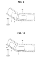
- Fig. 9 is a cross-sectional view illustrating a state in which the distal end portion of the insertion portion passes through the curved portion of the duct.
- Fig. 10 is a cross-sectional view illustrating a state in which the distal end portion of the insertion portion has passed through the curved portion of the duct.
- Fig. 11 is a side view illustrating an angle of the inclined portion formed in the distal end portion.
- Fig. 12 is a cross-sectional view illustrating the configuration of a distal end portion of a parent endoscope.
- an endoscope 1 that is an electronic endoscope of the present embodiment is principally constituted by an insertion portion 2 formed in a shape of an elongated tube, an operation portion 3 connected to a proximal end of the insertion portion 2, a universal cord 4 that is an endoscope cable that extends from the operation portion 3, an endoscope connector 5 arranged at a distal end of the universal cord 4, and the like.
- an electronic endoscope is mentioned as an example of the endoscope 1, the endoscope 1 is not limited thereto and may be a fiberscope that includes an ocular apparatus in the operation portion 3.
- the insertion portion 2 is a flexible tubular member formed by connecting a distal end portion 6, a bending portion 7 and a flexible tube portion 8 in that order from the distal end side.
- an image pickup unit that is an image pickup apparatus, described later, that contains image pickup means, and illumination means or the like are housed and disposed in the distal end portion 6.
- the bending portion 7 is a mechanism region configured to be actively bendable in the two directions of up and down (UP-DOWN) as point-symmetric directions around a central axis O1 (see Fig. 2 ) of the insertion portion 2 through a rotational operation of a bending lever 13 among operation members of the operation portion 3.
- UP-DOWN up and down
- the bending portion 7 is not limited to a type that actively bends in the two directions of up and down, and may also be of a type that is bendable in four directions that include the left/right directions in addition to the up/down directions (capable of bending in all circumferential directions, UP-DOWN/LEFT-RIGHT, around the axis through vertical and horizontal operations), or may also be of a type that is bendable in only the upward (UP) direction.
- the bending portion 7 may be of a type that merely bends passively and does not have a mechanism whereby the bending portion 7 is actively bent by the bending lever 13.
- the flexible tube portion 8 is a tubular member formed with flexibility so as to be passively flexible.
- a signal cable bundle that is described later that extends from the image pickup apparatus contained in the distal end portion 6 and runs from the operation portion 3 to the inside of the universal cord 4
- a light guide bundle that is described later that guides an illuminating light from an light source apparatus and causes the illuminating light to exit from the distal end portion 6 and the like are inserted through the inside of the flexible tube portion 8 (in this case, these members are not shown in the drawings).
- the operation portion 3 is constituted by: a bend preventing portion 9 that is provided on the distal end side to cover a proximal end of the flexible tube portion 8 and is connected to the flexible tube portion 8; a grasping portion 10 that is connected to the bend preventing portion 9 and which a user manually grasps when using the endoscope 1; operation means for operating various endoscope functions that are provided on an external surface of the grasping portion 10; a treatment instrument insertion portion 11; and a suction valve 15 or the like.
- Examples of the operation means provided in the operation portion 3 include the bending lever 13 for performing bending operations of the bending portion 7, and a plurality of operation members 14 for performing air/water feeding operations or suction operations or operations corresponding to the image pickup means, the illumination means or the like.
- the treatment instrument insertion portion 11 includes a treatment instrument insertion port for inserting various kinds of treatment instruments (not shown) and is a component that communicates with a treatment instrument insertion channel (not shown) through a branching member inside the operation portion 3.
- a forceps plug 12 that is a cap member for opening/closing the treatment instrument insertion port is arranged in the treatment instrument insertion portion 11.
- the forceps plug 12 is configured to be detachable (replaceable) from the treatment instrument insertion portion 11.
- the treatment instrument insertion channel is configured to also communicate with the suction valve 15 by means of the branching member within the operation portion 3.
- the universal cord 4 is a composite cable which extends through the inside of the insertion portion 2 from the distal end portion 6 of the insertion portion 2 to the operation portion 3, and through which a signal cable bundle and a light guide bundle that transmits an illuminating light from a light source apparatus (not shown) or the like are inserted.
- the endoscope connector 5 includes, on a side face portion, an electrical connector portion 16 to which is connected a signal cable that connects the endoscope 1 with a video processor (not shown) that is an external device, and also includes a light source connector portion 17 to which are connected a light guide bundle, described later, and an electrical cable (not shown) that connect the endoscope 1 with a light source apparatus that is an external device, and an air/water feeding plug 18 that connects an air/water feeding tube (not shown) from an air/water feeding apparatus (not shown) that is an external device.
- Fig. 2 and Fig. 3 The configuration of the insertion portion 2 of the endoscope 1 of the present embodiment will now be described based on Fig. 2 and Fig. 3 .
- a description relating to known components of the insertion portion 2 is omitted.
- the upward, downward, left and right directions (UP/DOWN/LEFT/RIGHT) illustrated in Fig. 2 and Fig. 3 correspond to and match the upward, downward, left and right directions in an observation image that is photographed by an image pickup unit 30 that is described later.
- the distal end portion 6 of the insertion portion 2 includes a distal end rigid portion 20 that is a metal block body in which an observation window 21, an illuminating window 22 and a channel opening portion 23 are provided.
- a distal end rigid portion 20 that is a metal block body in which an observation window 21, an illuminating window 22 and a channel opening portion 23 are provided.
- one section of an edge circumference portion on the distal end side is notched to form an inclined portion 24 as an inclined face. The configuration and action of the inclined portion 24 are described in detail later.
- the distal end portion 6 has an exterior tube 25 that is fitted and fixed to the exterior of the proximal end portion of the distal end rigid portion 20.
- the image pickup unit 30 that is an image pickup apparatus and illumination means, not illustrated in the drawings, are provided in the distal end rigid portion 20.
- a treatment instrument channel which is not illustrated in the drawings, is fitted and fixed inside the distal end rigid portion 20 so as to communicate with the channel opening portion 23.
- the treatment instrument channel passes through the inside of the insertion portion 2 from the distal end portion 6 of the insertion portion 2 to the operation portion 3, and communicates with the treatment instrument insertion port of the treatment instrument insertion portion 11 and the suction valve 15 illustrated in Fig. 1 .
- the image pickup unit 30 includes: a lens unit 33 in which a plurality of objective optical systems 31 including the observation window 21 are held in a lens holding barrel 32; a solid-state image pickup device 34 as image pickup means for detecting a subject image (observation image indicated by a photographing optical axis O in the drawing) that is formed by the objective optical systems 31; and a plurality of electronic components 35 mounted on an FPC that is electrically connected with the solid-state image pickup device 34 and the like.
- a plurality of small signal cables extend from the electronic components 35, and a signal cable bundle 36 that is formed by bundling the small signal cables extends from the image pickup unit 30 to the proximal end side.
- the signal cable bundle 36 that extends from the image pickup unit 30 is inserted through and disposed inside of the insertion portion 2, and is extended as far as the endoscope connector 5 via the operation portion 3 and the universal cord 4 shown in Fig. 1 , and connected to the electrical connector portion 16 of the endoscope connector 5.
- a heat-shrinkable tube 37 is provided from the proximal end portion of the lens unit 33 to the distal end portion of the signal cable bundle 36 so as to cover the plurality of electronic components 35 mounted on the FPC.
- An adhesive or the like for maintaining watertightness is filled inside the heat-shrinkable tube 37.
- the configuration of the image pickup unit 30 of the present embodiment that is described above is similar to the known conventional configuration, and hence a detailed description of the remaining configuration thereof is omitted here.
- the illumination means that is not illustrated in Fig. 3 has a configuration that includes a light guide bundle, not illustrated in the drawings, that is formed by bundling a plurality of fibers covered by an outer covering and that transmits an illuminating light, and which is fitted and retained in the distal end rigid portion 20 in a state in which a back face of the illuminating window 22 illustrated in Fig. 2 and a distal end face of the light guide bundle are opposingly disposed.
- a light guide bundle not illustrated in the drawings, that is formed by bundling a plurality of fibers covered by an outer covering and that transmits an illuminating light, and which is fitted and retained in the distal end rigid portion 20 in a state in which a back face of the illuminating window 22 illustrated in Fig. 2 and a distal end face of the light guide bundle are opposingly disposed.
- the light guide bundle is inserted through and disposed inside the insertion portion 2, and is extended as far as the endoscope connector 5 via the operation portion 3 and the universal cord 4 shown in Fig. 1 , and connected to the light source connector portion 17 of the endoscope connector 5.
- a plurality of bending pieces 41 that are made of metal are rotatably connected by pivoted portions 45 such as rivets, and a bending rubber 42 is covered over the outer circumference thereof to cover the plurality of bending pieces 41.
- the bending rubber 42 is preferably a multi-layered structure formed using a hard material on an outer layer side and a soft material on an inner layer side.
- a hard material on an outer layer side for example, polyurethane or the like is used as the hard material on the outer layer side, and fluorocarbon rubber or the like is used as the soft material on the inner layer side.
- the bending rubber 42 By forming the bending rubber 42 as a multi-layered structure in this manner, and using a hard material on the outer layer side, the resistance characteristics of the surface are enhanced, and furthermore, by providing the bending rubber 42 with resilience by using a soft material on the inner layer side, the shock resistance of the bending portion 7 improves.
- a bending piece disposed at the distalmost end among the plurality of bending pieces 41 described above is fitted and connected to the exterior of a small diameter portion at the proximal end of the exterior tube 25 connected to the proximal end portion of the distal end rigid portion 20 of the distal end portion 6.
- reference character "41 (41 a)" is assigned only to the bending piece disposed at the distalmost end among the plurality of bending pieces 41.
- the relevant bending piece is referred to as "bending piece 41a”.
- a distal end portion of the bending rubber 42 is bonded by an adhesive portion 43 so as to maintain watertightness with an outer peripheral portion of the bending piece 41a.
- a proximal end portion of the bending rubber 42 is also bonded by an adhesive portion (not shown) so that a connecting portion between the bending piece 41 a and the flexible tube portion 8 is maintained in a watertight state.
- the bending portion 7 is configured to be subjected to a bending operation in two directions, namely the upward/downward directions, of an observation image that the image pickup unit 30 picks up, in response to pulling/slackening of two bending operation wires 44 which are connected to the bending piece 41 a, through the plurality of bending pieces 41 in which the two bending operation wires 44 are inserted and held being rotated in a manner that utilizes the pivoted portions 45 as spindles.
- the two bending operation wires 44 are inserted through the inside of an unshown coil sheath in a region extending from the proximal end of the bending portion 7 to the inside of the flexible tube portion 8 and the operation portion 3, and are connected to a sprocket (not shown) that operates in response to operation of the bending lever 13. Note that since a configuration that causes the bending portion 7 to bend is known, a detailed description of the remaining configuration thereof is omitted here.
- the flexible tube portion 8 of the insertion portion 2 is formed as, for example, a flexible tube body having a triple layer structure constituted by an outer-layer resin, an inner-layer resin, and metal braid of a metal reticular tube that is provided between the outer-layer resin and the inner-layer resin.
- the metal braid may also be formed as a metal helical tube. Since the specific configuration of the flexible tube portion 8 is known, a detailed description of the remaining configuration thereof is omitted here.
- a curvature radius R1 at which the bending portion 7 bends to the maximum in the upward (UP) direction is set to be less than a curvature radius R2 at which the bending portion 7 bends to the maximum in the downward (DOWN) direction. That is, the bending portion 7 is set so that the curvature when the bending portion 7 is bent to the maximum in the upward direction is less than when the bending portion 7 is bent to the maximum in the downward direction, and the bend is sharp.
- the bending portion 7 is of a type that can bend in four directions (UP-DOWN/LEFT-RIGHT) that include the left/right directions in addition to the upward/downward directions also, a configuration is adopted so that the bending portion 7 can bend more in the upward direction than in the downward, left, and right directions. Further, in a case where bending portion 7 is of a type that can bend in only one direction which is the upward (UP) direction, the bending portion 7 does not bend in the downward, left, and right directions, and is in a rigid state with respect to those directions.
- UP-DOWN/LEFT-RIGHT UP-DOWN/LEFT-RIGHT
- the inclined portion 24 as an inclined face formed in the distal end portion 6 is formed so as to inclinedly intersect with a distal end face 20a of the distal end rigid portion 20 of the distal end portion 6 and respective side peripheral faces as side faces that serve as outer peripheral portions adjoining the distal end face 20a, and is substantially orthogonal to a ridge line 24a formed intersecting with the distal end face 20a and to the upward/downward (UP-DOWN) directions in which the bending portion 7 bends.
- UP-DOWN upward/downward
- the inclined portion 24 is formed to be parallel to the right/left (RIGHT-LEFT) directions in which the bending portion 7 bends, that is the side in the downward (DOWN) direction in which the bending portion 7 bends. That is, the inclined portion 24 is the downward direction of an observation image picked up by the image pickup unit 30 in the distal end rigid portion 20 of the distal end portion 6, and is formed parallel to the horizontal direction.
- the endoscope 1 of the present embodiment configured as described above, for example, as shown in Fig. 5 and Fig. 6 , when the distal end portion 6 of the insertion portion 2 that has been inserted into a duct 100 has come to a curved portion of the duct 100 which, in this case, curves to the left side, as the result of a manual operation performed by the user to push in the insertion portion 2, as shown in Fig. 7 and Fig. 8 , the inclined portion 24 formed in the distal end portion 6 contacts against the inner wall of the curved portion of the duct 100 and the insertion portion 2 rotates along the inner wall of the duct 100.
- the state is one in which the insertion portion 2 of the endoscope 1 is inserted into the duct 100 in a manner such that the front direction with respect to the page surface in Fig. 5 is the downward direction with respect to the direction in which the bending portion 7 bends.
- the upward, downward, left and right bending directions of the bending portion 7 rotate approximately 90° to enter the state illustrated in Fig. 8 from the state illustrated in Fig. 6 .
- the insertion portion 2 rotates counterclockwise as viewed from the user's side, and rotates clockwise as viewed facing the surface of the page of Fig. 6 and Fig. 8 .
- the endoscope 1 of the present embodiment when the distal end portion 6 of the insertion portion 2 is passed through the curved portion of the duct 100, as a result of the inclined portion 24 formed in the distal end portion 6 contacting against the inner wall of the curved portion, the insertion portion 2 naturally rotates and the curving direction of the duct 100 and the upward (UP) direction in which the bending portion 7 bends match.
- the insertion portion 2 is rotated so that the upward (UP) direction in which the bending portion 7 is bent with a small curvature radius matches the curving direction of the duct 100.
- the posture of the distal end portion 6 inclines along the curved portion of the duct 100, and as shown in Fig. 10 , the bending portion 7 bends passively in the upward direction and can easily pass through the curved portion of the duct 100.
- the bending portion 7 of the insertion portion 2 has a configuration that only bends in specific directions, which in this case are the two directions of upward and downward (UP-DOWN), and is in a rigid state with respect to the left/right (LEFT-RIGHT) directions. Consequently, to facilitate passage of the bending portion 7 of the insertion portion 2 through the curved portion of the duct 100, it is sufficient to cause the upward/downward directions of the bending portion 7 to match the curving direction of the duct 100, and the bending portion 7 passively bends along the inner wall of the duct 100. By this means, using a small amount of force to push in the insertion portion 2, the user can easily cause the insertion portion 2 to pass through the curved portion of the duct 100.
- the ability of the bending portion 7 of the insertion portion 2 to pass through the curved portion of the duct 100 is improved without increasing the manufacturing cost by a simple configuration in which the inclined portion 24 is formed on the lower side of the distal end portion 6.
- the present invention is not limited thereto.
- the present invention is also applicable to a ureteroscope that is inserted via a tube body that curves, or to a child endoscope that is inserted into a channel of a parent endoscope equipped with a raising base (also referred to as a "forceps base”) in a parent-and-child type endoscope.
- the endoscope 1 is a cholangioscope as a child endoscope of a parent-and-child type endoscope
- the raising base 201 of the duodenoscope may be formed of a material having a small friction coefficient, for example, tetrafluoroethylene (fluorocarbon resin), particularly a material having a low friction coefficient such as PTFE (polytetrafluoroethylene) or PFA (a tetrafluoroethylene perfluoroalkoxyethylene copolymer), and a coating material having a low friction coefficient, for example, chromium plating or a fluorocarbon resin may be coated on the inclined face 203 of the raising base 201.
- a material having a small friction coefficient for example, tetrafluoroethylene (fluorocarbon resin), particularly a material having a low friction coefficient such as PTFE (polytetrafluoroethylene) or PFA (a tetrafluoroethylene perfluoroalkoxyethylene copolymer), and a coating material having a low friction coefficient, for example, chromium plating or a fluorocarbon resin may be coated
- the configuration obtained by omitting the relevant configuration requirements can be extracted as an invention.
Landscapes
- Health & Medical Sciences (AREA)
- Life Sciences & Earth Sciences (AREA)
- Physics & Mathematics (AREA)
- Surgery (AREA)
- Optics & Photonics (AREA)
- Engineering & Computer Science (AREA)
- Medical Informatics (AREA)
- General Health & Medical Sciences (AREA)
- Pathology (AREA)
- Nuclear Medicine, Radiotherapy & Molecular Imaging (AREA)
- Biomedical Technology (AREA)
- Heart & Thoracic Surgery (AREA)
- Biophysics (AREA)
- Molecular Biology (AREA)
- Animal Behavior & Ethology (AREA)
- Radiology & Medical Imaging (AREA)
- Public Health (AREA)
- Veterinary Medicine (AREA)
- Astronomy & Astrophysics (AREA)
- General Physics & Mathematics (AREA)
- Multimedia (AREA)
- Gastroenterology & Hepatology (AREA)
- Urology & Nephrology (AREA)
- Endoscopes (AREA)
- Instruments For Viewing The Inside Of Hollow Bodies (AREA)
Abstract
Description
- The present invention relates to an endoscope including an insertion portion that includes a bending portion and that is inserted into a duct that curves.
- As is known, endoscopes are widely used for performing observation and treatment and the like inside the body (inside a body cavity) of a living organism, or for performing inspection and repairs in plant facilities for industrial use. Such endoscopes have an insertion portion for inserting into a duct that curves.
- A bending portion for improving the insertability into a duct is provided in the insertion portion of an endoscope. Such bending portions include a type that bends only in the two directions of upward and downward with respect to a photographed image that the endoscope photographs, and a type that bends in the four directions of upward, downward, left and right with respect to the aforementioned photographed image.
- For example, Japanese Patent Application Laid-Open Publication No.
2004-351138 - In the spatulate projection portion provided in the aforementioned conventional endoscope, an inclined portion is formed by a surface that extends from the distal end of the distal end portion to the base. The inclined portion is located in a direction in which the bending portion bends, and pushes against an inner wall of the lumen when the bending portion bends.
- Further, for example, in Japanese Patent Application Laid-Open Publication No.
2012-70934 - In this connection, the insertion portion of an endoscope has a configuration such that the bending portion can only bend in specific directions as described above. Consequently, there is the problem that, depending on the rotational posture around the longitudinal axis at the time of insertion, it may not be possible for the bending portion of the insertion portion to pass through a duct that curves to a small degree, or because passage through a curved part is difficult, a large amount of force is required to push in the insertion portion.
- In this regard, according to the endoscope technology disclosed in Japanese Patent Application Laid-Open Publication No.
2004-351138 2012-70934 - The present invention has been made in consideration of the above described problems, and an object of the present invention is to provide an endoscope that, by means of a simple configuration that does not increase the manufacturing cost, can improve the ability of a bending portion of an insertion portion to pass through a curved duct.
- An endoscope according to one aspect of the present invention includes: an insertion portion in which a distal end portion and a bending portion that is bendable in a desired direction are arranged; and an inclined face that is formed in the distal end portion, the inclined face being formed so as to inclinedly intersect with each side face adjoining a distal end face of the distal end portion, and being formed substantially orthogonal to a ridge line formed intersecting with the distal end face and to a direction in which the bending portion bends, wherein, by contacting against an inner wall of a curved portion of a duct into which the insertion portion is inserted, the inclined face varies a posture thereof so that the insertion portion is rotated and a bending direction of the bending portion matches a curving direction of the curved portion.
- According to the present invention described above, an endoscope can be provided that, by means of a simple configuration that does not increase the manufacturing cost, can improve the ability of a bending portion of an insertion portion to pass through a curved duct.
-
-
Fig. 1 is a perspective view illustrating a configuration of an endoscope according to one embodiment of the present invention; -
Fig. 2 is a front view illustrating a configuration of a distal end portion of an insertion portion; -
Fig. 3 is a cross-sectional view illustrating an internal configuration of the distal end portion of the insertion portion; -
Fig. 4 is a side view illustrating maximum bending states in the upward and downward directions of a bending portion of the insertion portion; -
Fig. 5 is a cross-sectional view illustrating a state in which the distal end portion of the insertion portion has arrived at a curved portion of a duct; -
Fig. 6 is a cross-sectional view along a line VI-VI inFig. 5 ; -
Fig. 7 is a cross-sectional view illustrating a state in which an inclined portion contacts against an inner wall of the curved portion of the duct, and the distal end portion rotates; -
Fig. 8 is a cross-sectional view along a line VIII-VIII inFig. 7 ; -
Fig. 9 is a cross-sectional view illustrating a state in which the distal end portion of the insertion portion passes through the curved portion of the duct; -
Fig. 10 is a cross-sectional view illustrating a state in which the distal end portion of the insertion portion has passed through the curved portion of the duct; -
Fig. 11 is a side view illustrating an angle of the inclined portion formed in the distal end portion; and -
Fig. 12 is a cross-sectional view illustrating the configuration of a distal end portion of a parent endoscope. - An embodiment of the present invention is described hereunder with reference to the drawings.
- It should be noted that, in the following description, drawings that are based on the embodiment are schematic ones in which the relationship between the thickness and width of each portion, the thickness ratios between the respective portions and the like are different from those of actual portions, and the drawings may include portions in which the dimensional relationships and ratios are different from one another.
- The drawings relate to one aspect to the present invention.
Fig. 1 is a perspective view illustrating a configuration of an electronic endoscope.Fig. 2 is a front view illustrating a configuration of a distal end portion of an insertion portion.Fig. 3 is a cross-sectional view illustrating an internal configuration of the distal end portion of the insertion portion.Fig. 4 is a side view illustrating maximum bending states in the upward and downward directions of a bending portion of the insertion portion.Fig. 5 is a cross-sectional view illustrating a state in which the distal end portion of the insertion portion has arrived at a curved portion of a duct.Fig. 6 is a cross-sectional view along a line VI-VI inFig. 5 .Fig. 7 is a cross-sectional view illustrating a state in which an inclined portion contacts against an inner wall of the curved portion of the duct, and the distal end portion rotates.Fig. 8 is a cross-sectional view along a line VIII-VIII inFig. 7 .Fig. 9 is a cross-sectional view illustrating a state in which the distal end portion of the insertion portion passes through the curved portion of the duct.Fig. 10 is a cross-sectional view illustrating a state in which the distal end portion of the insertion portion has passed through the curved portion of the duct.Fig. 11 is a side view illustrating an angle of the inclined portion formed in the distal end portion.Fig. 12 is a cross-sectional view illustrating the configuration of a distal end portion of a parent endoscope. - As shown in
Fig. 1 , anendoscope 1 that is an electronic endoscope of the present embodiment is principally constituted by aninsertion portion 2 formed in a shape of an elongated tube, anoperation portion 3 connected to a proximal end of theinsertion portion 2, a universal cord 4 that is an endoscope cable that extends from theoperation portion 3, anendoscope connector 5 arranged at a distal end of the universal cord 4, and the like. Note that, in this case, although an electronic endoscope is mentioned as an example of theendoscope 1, theendoscope 1 is not limited thereto and may be a fiberscope that includes an ocular apparatus in theoperation portion 3. - The
insertion portion 2 is a flexible tubular member formed by connecting adistal end portion 6, abending portion 7 and aflexible tube portion 8 in that order from the distal end side. Of these members, an image pickup unit that is an image pickup apparatus, described later, that contains image pickup means, and illumination means or the like are housed and disposed in thedistal end portion 6. - The
bending portion 7 is a mechanism region configured to be actively bendable in the two directions of up and down (UP-DOWN) as point-symmetric directions around a central axis O1 (seeFig. 2 ) of theinsertion portion 2 through a rotational operation of abending lever 13 among operation members of theoperation portion 3. - Note that the
bending portion 7 is not limited to a type that actively bends in the two directions of up and down, and may also be of a type that is bendable in four directions that include the left/right directions in addition to the up/down directions (capable of bending in all circumferential directions, UP-DOWN/LEFT-RIGHT, around the axis through vertical and horizontal operations), or may also be of a type that is bendable in only the upward (UP) direction. Furthermore, thebending portion 7 may be of a type that merely bends passively and does not have a mechanism whereby thebending portion 7 is actively bent by thebending lever 13. - The
flexible tube portion 8 is a tubular member formed with flexibility so as to be passively flexible. In addition to a treatment instrument insertion channel that is described later, a signal cable bundle that is described later that extends from the image pickup apparatus contained in thedistal end portion 6 and runs from theoperation portion 3 to the inside of the universal cord 4, and a light guide bundle that is described later that guides an illuminating light from an light source apparatus and causes the illuminating light to exit from thedistal end portion 6 and the like are inserted through the inside of the flexible tube portion 8 (in this case, these members are not shown in the drawings). - The
operation portion 3 is constituted by: abend preventing portion 9 that is provided on the distal end side to cover a proximal end of theflexible tube portion 8 and is connected to theflexible tube portion 8; agrasping portion 10 that is connected to thebend preventing portion 9 and which a user manually grasps when using theendoscope 1; operation means for operating various endoscope functions that are provided on an external surface of thegrasping portion 10; a treatmentinstrument insertion portion 11; and asuction valve 15 or the like. - Examples of the operation means provided in the
operation portion 3 include thebending lever 13 for performing bending operations of thebending portion 7, and a plurality ofoperation members 14 for performing air/water feeding operations or suction operations or operations corresponding to the image pickup means, the illumination means or the like. - The treatment
instrument insertion portion 11 includes a treatment instrument insertion port for inserting various kinds of treatment instruments (not shown) and is a component that communicates with a treatment instrument insertion channel (not shown) through a branching member inside theoperation portion 3. - A
forceps plug 12 that is a cap member for opening/closing the treatment instrument insertion port is arranged in the treatmentinstrument insertion portion 11. Theforceps plug 12 is configured to be detachable (replaceable) from the treatmentinstrument insertion portion 11. Note that, the treatment instrument insertion channel is configured to also communicate with thesuction valve 15 by means of the branching member within theoperation portion 3. - The universal cord 4 is a composite cable which extends through the inside of the
insertion portion 2 from thedistal end portion 6 of theinsertion portion 2 to theoperation portion 3, and through which a signal cable bundle and a light guide bundle that transmits an illuminating light from a light source apparatus (not shown) or the like are inserted. - The
endoscope connector 5 includes, on a side face portion, anelectrical connector portion 16 to which is connected a signal cable that connects theendoscope 1 with a video processor (not shown) that is an external device, and also includes a lightsource connector portion 17 to which are connected a light guide bundle, described later, and an electrical cable (not shown) that connect theendoscope 1 with a light source apparatus that is an external device, and an air/water feeding plug 18 that connects an air/water feeding tube (not shown) from an air/water feeding apparatus (not shown) that is an external device. - The configuration of the
insertion portion 2 of theendoscope 1 of the present embodiment will now be described based onFig. 2 andFig. 3 . Note that, in the following description, a description relating to known components of theinsertion portion 2 is omitted. Note that, the upward, downward, left and right directions (UP/DOWN/LEFT/RIGHT) illustrated inFig. 2 andFig. 3 correspond to and match the upward, downward, left and right directions in an observation image that is photographed by animage pickup unit 30 that is described later. - As shown in
Fig. 2 , thedistal end portion 6 of theinsertion portion 2 includes a distal endrigid portion 20 that is a metal block body in which anobservation window 21, an illuminatingwindow 22 and achannel opening portion 23 are provided. In the distal endrigid portion 20, one section of an edge circumference portion on the distal end side is notched to form aninclined portion 24 as an inclined face. The configuration and action of theinclined portion 24 are described in detail later. - Further, as shown in
Fig. 3 , thedistal end portion 6 has anexterior tube 25 that is fitted and fixed to the exterior of the proximal end portion of the distal endrigid portion 20. Theimage pickup unit 30 that is an image pickup apparatus and illumination means, not illustrated in the drawings, are provided in the distal endrigid portion 20. A treatment instrument channel, which is not illustrated in the drawings, is fitted and fixed inside the distal endrigid portion 20 so as to communicate with thechannel opening portion 23. - Note that the treatment instrument channel passes through the inside of the
insertion portion 2 from thedistal end portion 6 of theinsertion portion 2 to theoperation portion 3, and communicates with the treatment instrument insertion port of the treatmentinstrument insertion portion 11 and thesuction valve 15 illustrated inFig. 1 . - The
image pickup unit 30 includes: alens unit 33 in which a plurality of objectiveoptical systems 31 including theobservation window 21 are held in alens holding barrel 32; a solid-stateimage pickup device 34 as image pickup means for detecting a subject image (observation image indicated by a photographing optical axis O in the drawing) that is formed by the objectiveoptical systems 31; and a plurality ofelectronic components 35 mounted on an FPC that is electrically connected with the solid-stateimage pickup device 34 and the like. - A plurality of small signal cables extend from the
electronic components 35, and asignal cable bundle 36 that is formed by bundling the small signal cables extends from theimage pickup unit 30 to the proximal end side. - The
signal cable bundle 36 that extends from theimage pickup unit 30 is inserted through and disposed inside of theinsertion portion 2, and is extended as far as theendoscope connector 5 via theoperation portion 3 and the universal cord 4 shown inFig. 1 , and connected to theelectrical connector portion 16 of theendoscope connector 5. - A heat-
shrinkable tube 37 is provided from the proximal end portion of thelens unit 33 to the distal end portion of thesignal cable bundle 36 so as to cover the plurality ofelectronic components 35 mounted on the FPC. An adhesive or the like for maintaining watertightness is filled inside the heat-shrinkable tube 37. - The configuration of the
image pickup unit 30 of the present embodiment that is described above is similar to the known conventional configuration, and hence a detailed description of the remaining configuration thereof is omitted here. - The illumination means that is not illustrated in
Fig. 3 has a configuration that includes a light guide bundle, not illustrated in the drawings, that is formed by bundling a plurality of fibers covered by an outer covering and that transmits an illuminating light, and which is fitted and retained in the distal endrigid portion 20 in a state in which a back face of the illuminatingwindow 22 illustrated inFig. 2 and a distal end face of the light guide bundle are opposingly disposed. - Note that the light guide bundle is inserted through and disposed inside the
insertion portion 2, and is extended as far as theendoscope connector 5 via theoperation portion 3 and the universal cord 4 shown inFig. 1 , and connected to the lightsource connector portion 17 of theendoscope connector 5. - In the bending
portion 7 of theinsertion portion 2, a plurality of bendingpieces 41 that are made of metal are rotatably connected by pivotedportions 45 such as rivets, and a bendingrubber 42 is covered over the outer circumference thereof to cover the plurality of bendingpieces 41. - Note that the bending
rubber 42 is preferably a multi-layered structure formed using a hard material on an outer layer side and a soft material on an inner layer side. As the bendingrubber 42 having a multi-layered structure, for example, polyurethane or the like is used as the hard material on the outer layer side, and fluorocarbon rubber or the like is used as the soft material on the inner layer side. - By forming the bending
rubber 42 as a multi-layered structure in this manner, and using a hard material on the outer layer side, the resistance characteristics of the surface are enhanced, and furthermore, by providing the bendingrubber 42 with resilience by using a soft material on the inner layer side, the shock resistance of the bendingportion 7 improves. - A bending piece disposed at the distalmost end among the plurality of bending
pieces 41 described above is fitted and connected to the exterior of a small diameter portion at the proximal end of theexterior tube 25 connected to the proximal end portion of the distal endrigid portion 20 of thedistal end portion 6. Note that, inFig. 3 , reference character "41 (41 a)" is assigned only to the bending piece disposed at the distalmost end among the plurality of bendingpieces 41. In the following description, the relevant bending piece is referred to as "bendingpiece 41a". - A distal end portion of the bending
rubber 42 is bonded by anadhesive portion 43 so as to maintain watertightness with an outer peripheral portion of thebending piece 41a. A proximal end portion of the bendingrubber 42 is also bonded by an adhesive portion (not shown) so that a connecting portion between the bendingpiece 41 a and theflexible tube portion 8 is maintained in a watertight state. - In this case, the bending
portion 7 is configured to be subjected to a bending operation in two directions, namely the upward/downward directions, of an observation image that theimage pickup unit 30 picks up, in response to pulling/slackening of two bendingoperation wires 44 which are connected to thebending piece 41 a, through the plurality of bendingpieces 41 in which the two bendingoperation wires 44 are inserted and held being rotated in a manner that utilizes the pivotedportions 45 as spindles. - The two
bending operation wires 44 are inserted through the inside of an unshown coil sheath in a region extending from the proximal end of the bendingportion 7 to the inside of theflexible tube portion 8 and theoperation portion 3, and are connected to a sprocket (not shown) that operates in response to operation of the bendinglever 13. Note that since a configuration that causes the bendingportion 7 to bend is known, a detailed description of the remaining configuration thereof is omitted here. - Although not shown in the drawings, the
flexible tube portion 8 of theinsertion portion 2 is formed as, for example, a flexible tube body having a triple layer structure constituted by an outer-layer resin, an inner-layer resin, and metal braid of a metal reticular tube that is provided between the outer-layer resin and the inner-layer resin. Note that the metal braid may also be formed as a metal helical tube. Since the specific configuration of theflexible tube portion 8 is known, a detailed description of the remaining configuration thereof is omitted here. - In this connection, as shown in
Fig. 4 , with respect to the bendingportion 7 of the present embodiment, a curvature radius R1 at which the bendingportion 7 bends to the maximum in the upward (UP) direction is set to be less than a curvature radius R2 at which the bendingportion 7 bends to the maximum in the downward (DOWN) direction. That is, the bendingportion 7 is set so that the curvature when the bendingportion 7 is bent to the maximum in the upward direction is less than when the bendingportion 7 is bent to the maximum in the downward direction, and the bend is sharp. - Note that, as described above, in a case where the bending
portion 7 is of a type that can bend in four directions (UP-DOWN/LEFT-RIGHT) that include the left/right directions in addition to the upward/downward directions also, a configuration is adopted so that the bendingportion 7 can bend more in the upward direction than in the downward, left, and right directions. Further, in a case where bendingportion 7 is of a type that can bend in only one direction which is the upward (UP) direction, the bendingportion 7 does not bend in the downward, left, and right directions, and is in a rigid state with respect to those directions. - As shown in
Fig. 2 andFig. 3 , theinclined portion 24 as an inclined face formed in thedistal end portion 6 is formed so as to inclinedly intersect with adistal end face 20a of the distal endrigid portion 20 of thedistal end portion 6 and respective side peripheral faces as side faces that serve as outer peripheral portions adjoining thedistal end face 20a, and is substantially orthogonal to aridge line 24a formed intersecting with thedistal end face 20a and to the upward/downward (UP-DOWN) directions in which the bendingportion 7 bends. - Further, the
inclined portion 24 is formed to be parallel to the right/left (RIGHT-LEFT) directions in which the bendingportion 7 bends, that is the side in the downward (DOWN) direction in which the bendingportion 7 bends. That is, theinclined portion 24 is the downward direction of an observation image picked up by theimage pickup unit 30 in the distal endrigid portion 20 of thedistal end portion 6, and is formed parallel to the horizontal direction. - According to the
endoscope 1 of the present embodiment configured as described above, for example, as shown inFig. 5 and Fig. 6 , when thedistal end portion 6 of theinsertion portion 2 that has been inserted into aduct 100 has come to a curved portion of theduct 100 which, in this case, curves to the left side, as the result of a manual operation performed by the user to push in theinsertion portion 2, as shown inFig. 7 and Fig. 8 , theinclined portion 24 formed in thedistal end portion 6 contacts against the inner wall of the curved portion of theduct 100 and theinsertion portion 2 rotates along the inner wall of theduct 100. - That is, when the
inclined portion 24 of thedistal end portion 6 comes in contact with the inner wall of the curved portion of theduct 100, and theinsertion portion 2 of theendoscope 1 is then pushed in further, a rotary force arises in thedistal end portion 6 such that theinclined portion 24 is guided by the inner wall of the duct and rotates in accordance therewith. - Note that, in this case, the state is one in which the
insertion portion 2 of theendoscope 1 is inserted into theduct 100 in a manner such that the front direction with respect to the page surface inFig. 5 is the downward direction with respect to the direction in which the bendingportion 7 bends. - Further, in the
insertion portion 2, the upward, downward, left and right bending directions of the bendingportion 7 rotate approximately 90° to enter the state illustrated inFig. 8 from the state illustrated inFig. 6 . In this case, because theduct 100 curves to the left (LEFT) direction, theinsertion portion 2 rotates counterclockwise as viewed from the user's side, and rotates clockwise as viewed facing the surface of the page ofFig. 6 andFig. 8 . - Thus, according to the
endoscope 1 of the present embodiment, when thedistal end portion 6 of theinsertion portion 2 is passed through the curved portion of theduct 100, as a result of theinclined portion 24 formed in thedistal end portion 6 contacting against the inner wall of the curved portion, theinsertion portion 2 naturally rotates and the curving direction of theduct 100 and the upward (UP) direction in which the bendingportion 7 bends match. - That is, since the
inclined portion 24 of thedistal end portion 6 is formed on the downward (DOWN) direction side in which the bendingportion 7 bends, theinsertion portion 2 is rotated so that the upward (UP) direction in which the bendingportion 7 is bent with a small curvature radius matches the curving direction of theduct 100. - When the
insertion portion 2 of theendoscope 1 is pushed in further in the direction of the deep part of theduct 100, as shown inFig. 9 , the posture of thedistal end portion 6 inclines along the curved portion of theduct 100, and as shown inFig. 10 , the bendingportion 7 bends passively in the upward direction and can easily pass through the curved portion of theduct 100. - Note that, the bending
portion 7 of theinsertion portion 2 has a configuration that only bends in specific directions, which in this case are the two directions of upward and downward (UP-DOWN), and is in a rigid state with respect to the left/right (LEFT-RIGHT) directions. Consequently, to facilitate passage of the bendingportion 7 of theinsertion portion 2 through the curved portion of theduct 100, it is sufficient to cause the upward/downward directions of the bendingportion 7 to match the curving direction of theduct 100, and the bendingportion 7 passively bends along the inner wall of theduct 100. By this means, using a small amount of force to push in theinsertion portion 2, the user can easily cause theinsertion portion 2 to pass through the curved portion of theduct 100. - As described above, according to the
endoscope 1 of the present embodiment, the ability of the bendingportion 7 of theinsertion portion 2 to pass through the curved portion of theduct 100 is improved without increasing the manufacturing cost by a simple configuration in which theinclined portion 24 is formed on the lower side of thedistal end portion 6. - Note that, with respect to the technology of the above described
endoscope 1, although an example in which theinsertion portion 2 is caused to pass through the curved portion of theduct 100 is described above, the present invention is not limited thereto. For example, the present invention is also applicable to a ureteroscope that is inserted via a tube body that curves, or to a child endoscope that is inserted into a channel of a parent endoscope equipped with a raising base (also referred to as a "forceps base") in a parent-and-child type endoscope. - Further, in a case where the
endoscope 1 is a cholangioscope as a child endoscope of a parent-and-child type endoscope, it is favorable to cause an angle θ2 formed between an angle of inclination of aninclined face 203 at which an insertion path of theinsertion portion 2 is bent in the vicinity of a distal end opening of a channel 102 that is provided in a raisingbase 201 provided in adistal end portion 200 of a duodenoscope as a parent endoscope that is shown inFig. 12 and a hole axis X as a central axis of the channel 102 through which the cholangioscope is inserted to substantially match an angle of inclination θ1 (θ1 ≈ θ2) of theinclined portion 24 formed in thedistal end portion 6 that is shown inFig. 11 . - By this means, because the
inclined portion 24 formed in thedistal end portion 6 of the insertion portion of the cholangioscope comes into surface contact with theinclined face 203 of the raisingbase 201 of the duodenoscope and is guided along the inclined face of the raisingbase 201, the resistance from the raisingbase 201 is reduced, and insertion and withdrawal of the insertion portion of the cholangioscope can be smoothly performed, and insertion/withdrawal failures and damage and the like can be prevented. - Note that, the raising
base 201 of the duodenoscope may be formed of a material having a small friction coefficient, for example, tetrafluoroethylene (fluorocarbon resin), particularly a material having a low friction coefficient such as PTFE (polytetrafluoroethylene) or PFA (a tetrafluoroethylene perfluoroalkoxyethylene copolymer), and a coating material having a low friction coefficient, for example, chromium plating or a fluorocarbon resin may be coated on theinclined face 203 of the raisingbase 201. - The invention described in the foregoing embodiment is not limited to the embodiment and modifications described above, and various modifications can be implemented within a range that does not deviate from the spirit of the present invention in the implementing stage. Further, the above described embodiment includes inventions of various stages, and various inventions can be extracted by appropriately combining a plurality of the disclosed configuration requirements.
- For example, if the problem to be solved by the invention can be solved and the described effects of the invention are obtained even after omitting some of the configuration requirements from the entire configuration requirements disclosed according to the embodiment, then the configuration obtained by omitting the relevant configuration requirements can be extracted as an invention.
- The present application claims priority from Japanese Patent Application No.
2013-110928
Claims (9)
- An endoscope, comprising:an insertion portion in which a distal end portion and a bending portion that is bendable in a desired direction are arranged; andan inclined face that is formed in the distal end portion, the inclined face being formed so as to inclinedly intersect with each side face adjoining a distal end face of the distal end portion, and being formed substantially orthogonal to a ridge line formed intersecting with the distal end face and to a direction in which the bending portion bends, wherein, by contacting against an inner wall of a curved portion of a duct into which the insertion portion is inserted, the inclined face varies a posture thereof so that the insertion portion is rotated and a bending direction of the bending portion matches a curving direction of the curved portion.
- The endoscope according to claim 1, wherein:the bending portion bends only in two directions that are point-symmetric directions around a central axis of the insertion portion, andthe ridge line of the inclined face is substantially orthogonal to the two directions.
- The endoscope according to claim 2, wherein:among the two directions, the inclined face is formed in a second bending direction that is on an opposite side to a first bending direction in which a curvature at a time of maximum bending of the bending portion is smaller.
- The endoscope according to claim 2 or 3, further comprising image pickup means for picking up an image of a subject,
wherein the two directions are an upward direction and a downward direction with respect to an observation image of the image pickup means. - The endoscope according to claim 1, wherein:the bending portion bends only in one direction, andthe ridge line of the inclined face is substantially orthogonal to the one direction.
- The endoscope according to claim 5, further comprising image pickup means for picking up an image of a subject,
wherein the one direction is an upward direction with respect to an observation image of the image pickup means. - The endoscope according to any one of claims 1 to 6, wherein the insertion portion is a cholangioscope that is insertable into and withdrawable from inside of a channel of a duodenoscope.
- The endoscope according to claim 7, wherein an angle formed between an inclined face of a raising base provided in the duodenoscope at which an insertion path of the insertion portion is bent in a vicinity of a distal end opening of the channel and a hole axis of the channel is caused to substantially match an angle of inclination of the inclined face.
- The endoscope according to any one of claims 1 to 6, wherein the bending portion is passively bendable in the desired direction.
Applications Claiming Priority (2)
| Application Number | Priority Date | Filing Date | Title |
|---|---|---|---|
| JP2013110928 | 2013-05-27 | ||
| PCT/JP2014/057854 WO2014192386A1 (en) | 2013-05-27 | 2014-03-20 | Endoscope |
Publications (2)
| Publication Number | Publication Date |
|---|---|
| EP2870909A1 true EP2870909A1 (en) | 2015-05-13 |
| EP2870909A4 EP2870909A4 (en) | 2016-07-06 |
Family
ID=51988430
Family Applications (1)
| Application Number | Title | Priority Date | Filing Date |
|---|---|---|---|
| EP14804821.8A Withdrawn EP2870909A4 (en) | 2013-05-27 | 2014-03-20 | Endoscope |
Country Status (5)
| Country | Link |
|---|---|
| US (1) | US20150157189A1 (en) |
| EP (1) | EP2870909A4 (en) |
| JP (1) | JP5663709B1 (en) |
| CN (1) | CN104602588B (en) |
| WO (1) | WO2014192386A1 (en) |
Families Citing this family (9)
| Publication number | Priority date | Publication date | Assignee | Title |
|---|---|---|---|---|
| USD753298S1 (en) * | 2014-06-30 | 2016-04-05 | Hoya Corporation | Endoscope control grip |
| USD753823S1 (en) * | 2014-06-30 | 2016-04-12 | Hoya Corporation | Endoscope control grip |
| USD775334S1 (en) * | 2014-06-30 | 2016-12-27 | Hoya Corporation | Endoscope control grip |
| USD761420S1 (en) | 2014-06-30 | 2016-07-12 | Hoya Corporation | Endoscope suction valve |
| JP5989277B2 (en) * | 2014-09-04 | 2016-09-07 | オリンパス株式会社 | Endoscope tip structure |
| PL235947B1 (en) * | 2016-11-01 | 2020-11-16 | Endoscope Spolka Z Ograniczona Odpowiedzialnoscia | Flexible endoscope |
| CN109788892B (en) * | 2016-12-05 | 2021-10-12 | 奥林巴斯株式会社 | Electronic circuit unit, imaging unit, and endoscope |
| KR102615972B1 (en) | 2017-03-03 | 2023-12-21 | 보스톤 싸이엔티픽 싸이메드 인코포레이티드 | device tips |
| CN113876284A (en) * | 2020-07-03 | 2022-01-04 | 杭州莱恩瑟特医疗技术有限公司 | Electronic endoscope |
Family Cites Families (20)
| Publication number | Priority date | Publication date | Assignee | Title |
|---|---|---|---|---|
| CH225716A (en) * | 1940-12-24 | 1943-02-15 | Sandoz Ag | Process for preparing an anthraquinone derivative. |
| US3913568A (en) * | 1973-01-22 | 1975-10-21 | American Optical Corp | Nasopharyngoscope |
| JPS62283309A (en) * | 1986-05-21 | 1987-12-09 | Olympus Optical Co Ltd | Tip part of endoscope |
| US4911148A (en) * | 1989-03-14 | 1990-03-27 | Intramed Laboratories, Inc. | Deflectable-end endoscope with detachable flexible shaft assembly |
| US5305736A (en) * | 1991-04-26 | 1994-04-26 | Asahi Kogaku Kogyo Kabushiki Kaisha | Distal end part of endoscope |
| JP3780046B2 (en) * | 1995-12-15 | 2006-05-31 | オリンパス株式会社 | Endoscope |
| US5871440A (en) * | 1995-12-15 | 1999-02-16 | Olympus Optical Co., Ltd. | Endoscope |
| US5916147A (en) * | 1997-09-22 | 1999-06-29 | Boury; Harb N. | Selectively manipulable catheter |
| JP3854946B2 (en) * | 2003-05-30 | 2006-12-06 | オリンパス株式会社 | Endoscope |
| JP2005013708A (en) * | 2003-05-30 | 2005-01-20 | Olympus Corp | Endoscope and method for assembling it |
| JP2005095582A (en) * | 2003-08-21 | 2005-04-14 | Olympus Corp | Hood for endoscope |
| JP4533695B2 (en) * | 2003-09-23 | 2010-09-01 | オリンパス株式会社 | Treatment endoscope |
| JP2006068393A (en) * | 2004-09-03 | 2006-03-16 | Olympus Corp | Endoscope |
| JP4959579B2 (en) * | 2005-12-01 | 2012-06-27 | オリンパスメディカルシステムズ株式会社 | Elongated medical material |
| ATE498352T1 (en) * | 2007-03-01 | 2011-03-15 | Jorge A Campos | SURFACE TIP ARRANGEMENT FOR AN ENDOSCOPE |
| JP5313068B2 (en) * | 2009-03-09 | 2013-10-09 | 富士フイルム株式会社 | Endoscopic endoscope device |
| WO2011108142A1 (en) * | 2010-03-03 | 2011-09-09 | オリンパスメディカルシステムズ株式会社 | Treatment device |
| JP5006478B2 (en) * | 2010-08-05 | 2012-08-22 | オリンパスメディカルシステムズ株式会社 | Endoscope |
| JP5604247B2 (en) * | 2010-09-28 | 2014-10-08 | 富士フイルム株式会社 | Endoscope device |
| JP2012075658A (en) * | 2010-09-30 | 2012-04-19 | Fujifilm Corp | Endoscope apparatus |
-
2014
- 2014-03-20 JP JP2014536462A patent/JP5663709B1/en active Active
- 2014-03-20 CN CN201480002266.8A patent/CN104602588B/en active Active
- 2014-03-20 WO PCT/JP2014/057854 patent/WO2014192386A1/en active Application Filing
- 2014-03-20 EP EP14804821.8A patent/EP2870909A4/en not_active Withdrawn
-
2015
- 2015-02-13 US US14/621,476 patent/US20150157189A1/en not_active Abandoned
Also Published As
| Publication number | Publication date |
|---|---|
| CN104602588B (en) | 2016-09-28 |
| WO2014192386A1 (en) | 2014-12-04 |
| JPWO2014192386A1 (en) | 2017-02-23 |
| CN104602588A (en) | 2015-05-06 |
| EP2870909A4 (en) | 2016-07-06 |
| JP5663709B1 (en) | 2015-02-04 |
| US20150157189A1 (en) | 2015-06-11 |
Similar Documents
| Publication | Publication Date | Title |
|---|---|---|
| EP2870909A1 (en) | Endoscope | |
| EP1554972B1 (en) | Endoscope device | |
| CN100558285C (en) | Endoscope insertion part, endoscope and endoscopic system | |
| US10321806B2 (en) | Endoscope and rigid distal end portion of endoscope | |
| JP5390048B1 (en) | Endoscope system | |
| JP6349041B1 (en) | Curved tube and endoscope | |
| EP3135182A1 (en) | Endoscope bending section and endoscope | |
| US6572535B2 (en) | Endoscope | |
| US20220151480A1 (en) | Medical visualisation device | |
| CN110545708B (en) | Endoscope bending portion and endoscope | |
| JP2007054400A (en) | Endoscope | |
| CN108348138A (en) | Endoscope | |
| JP3510343B2 (en) | Electronic endoscope | |
| CN114727750A (en) | Endoscope with a detachable handle | |
| JP2007037566A (en) | Endoscope | |
| JP2004121860A (en) | Endoscope system | |
| CN112423642A (en) | Endoscope with a detachable handle | |
| JP2020075043A (en) | Endoscope | |
| JP2005304545A (en) | Endoscope | |
| JP2012213572A (en) | Supplementary observation device for endoscope | |
| JP5220446B2 (en) | Endoscope | |
| JP2018175225A (en) | Endoscope system | |
| JP3597416B2 (en) | Endoscope | |
| JP2002034904A (en) | Therapy accessory insertion passage of endoscope | |
| JP2017018274A (en) | Stent-placement endoscope hood and endoscope system |
Legal Events
| Date | Code | Title | Description |
|---|---|---|---|
| PUAI | Public reference made under article 153(3) epc to a published international application that has entered the european phase |
Free format text: ORIGINAL CODE: 0009012 |
|
| 17P | Request for examination filed |
Effective date: 20150206 |
|
| AK | Designated contracting states |
Kind code of ref document: A1 Designated state(s): AL AT BE BG CH CY CZ DE DK EE ES FI FR GB GR HR HU IE IS IT LI LT LU LV MC MK MT NL NO PL PT RO RS SE SI SK SM TR |
|
| AX | Request for extension of the european patent |
Extension state: BA ME |
|
| RAP1 | Party data changed (applicant data changed or rights of an application transferred) |
Owner name: OLYMPUS CORPORATION |
|
| RA4 | Supplementary search report drawn up and despatched (corrected) |
Effective date: 20160606 |
|
| RIC1 | Information provided on ipc code assigned before grant |
Ipc: A61B 1/307 20060101ALI20160531BHEP Ipc: A61B 1/273 20060101ALI20160531BHEP Ipc: G02B 23/24 20060101ALI20160531BHEP Ipc: A61B 1/00 20060101AFI20160531BHEP Ipc: A61B 1/005 20060101ALI20160531BHEP Ipc: A61B 1/04 20060101ALI20160531BHEP Ipc: A61B 1/012 20060101ALI20160531BHEP |
|
| DAX | Request for extension of the european patent (deleted) | ||
| RAP1 | Party data changed (applicant data changed or rights of an application transferred) |
Owner name: OLYMPUS CORPORATION |
|
| RAP1 | Party data changed (applicant data changed or rights of an application transferred) |
Owner name: OLYMPUS CORPORATION |
|
| RIN1 | Information on inventor provided before grant (corrected) |
Inventor name: SHIMADA NAOYA |
|
| STAA | Information on the status of an ep patent application or granted ep patent |
Free format text: STATUS: EXAMINATION IS IN PROGRESS |
|
| 17Q | First examination report despatched |
Effective date: 20170516 |
|
| STAA | Information on the status of an ep patent application or granted ep patent |
Free format text: STATUS: THE APPLICATION IS DEEMED TO BE WITHDRAWN |
|
| 18D | Application deemed to be withdrawn |
Effective date: 20180705 |