EP2870257B1 - Apparatus and methods for detecting atp in a liquid sample - Google Patents
Apparatus and methods for detecting atp in a liquid sample Download PDFInfo
- Publication number
- EP2870257B1 EP2870257B1 EP13710925.2A EP13710925A EP2870257B1 EP 2870257 B1 EP2870257 B1 EP 2870257B1 EP 13710925 A EP13710925 A EP 13710925A EP 2870257 B1 EP2870257 B1 EP 2870257B1
- Authority
- EP
- European Patent Office
- Prior art keywords
- sample
- reagent composition
- sampling device
- liquid
- liquid reagent
- Prior art date
- Legal status (The legal status is an assumption and is not a legal conclusion. Google has not performed a legal analysis and makes no representation as to the accuracy of the status listed.)
- Active
Links
- 239000007788 liquid Substances 0.000 title claims description 186
- 238000000034 method Methods 0.000 title description 78
- 238000005070 sampling Methods 0.000 claims description 194
- 239000003153 chemical reaction reagent Substances 0.000 claims description 155
- 239000000203 mixture Substances 0.000 claims description 132
- 108060001084 Luciferase Proteins 0.000 claims description 60
- 238000000576 coating method Methods 0.000 claims description 36
- 239000011248 coating agent Substances 0.000 claims description 35
- 230000000694 effects Effects 0.000 claims description 21
- IGXWBGJHJZYPQS-SSDOTTSWSA-N D-Luciferin Chemical compound OC(=O)[C@H]1CSC(C=2SC3=CC=C(O)C=C3N=2)=N1 IGXWBGJHJZYPQS-SSDOTTSWSA-N 0.000 claims description 17
- CYCGRDQQIOGCKX-UHFFFAOYSA-N Dehydro-luciferin Natural products OC(=O)C1=CSC(C=2SC3=CC(O)=CC=C3N=2)=N1 CYCGRDQQIOGCKX-UHFFFAOYSA-N 0.000 claims description 15
- BJGNCJDXODQBOB-UHFFFAOYSA-N Fivefly Luciferin Natural products OC(=O)C1CSC(C=2SC3=CC(O)=CC=C3N=2)=N1 BJGNCJDXODQBOB-UHFFFAOYSA-N 0.000 claims description 15
- DDWFXDSYGUXRAY-UHFFFAOYSA-N Luciferin Natural products CCc1c(C)c(CC2NC(=O)C(=C2C=C)C)[nH]c1Cc3[nH]c4C(=C5/NC(CC(=O)O)C(C)C5CC(=O)O)CC(=O)c4c3C DDWFXDSYGUXRAY-UHFFFAOYSA-N 0.000 claims description 15
- SEQKRHFRPICQDD-UHFFFAOYSA-N N-tris(hydroxymethyl)methylglycine Chemical compound OCC(CO)(CO)[NH2+]CC([O-])=O SEQKRHFRPICQDD-UHFFFAOYSA-N 0.000 claims description 15
- 239000005089 Luciferase Substances 0.000 claims description 13
- 239000006261 foam material Substances 0.000 claims description 13
- 239000000872 buffer Substances 0.000 claims description 12
- 239000003638 chemical reducing agent Substances 0.000 claims description 7
- 239000003599 detergent Substances 0.000 claims description 7
- JKMHFZQWWAIEOD-UHFFFAOYSA-N 2-[4-(2-hydroxyethyl)piperazin-1-yl]ethanesulfonic acid Chemical compound OCC[NH+]1CCN(CCS([O-])(=O)=O)CC1 JKMHFZQWWAIEOD-UHFFFAOYSA-N 0.000 claims description 6
- 229910019142 PO4 Inorganic materials 0.000 claims description 4
- NBIIXXVUZAFLBC-UHFFFAOYSA-K phosphate Chemical compound [O-]P([O-])([O-])=O NBIIXXVUZAFLBC-UHFFFAOYSA-K 0.000 claims description 4
- 239000010452 phosphate Substances 0.000 claims description 4
- 239000007995 HEPES buffer Substances 0.000 claims description 3
- 230000000052 comparative effect Effects 0.000 description 45
- ZKHQWZAMYRWXGA-KQYNXXCUSA-J ATP(4-) Chemical compound C1=NC=2C(N)=NC=NC=2N1[C@@H]1O[C@H](COP([O-])(=O)OP([O-])(=O)OP([O-])([O-])=O)[C@@H](O)[C@H]1O ZKHQWZAMYRWXGA-KQYNXXCUSA-J 0.000 description 43
- ZKHQWZAMYRWXGA-UHFFFAOYSA-N Adenosine triphosphate Natural products C1=NC=2C(N)=NC=NC=2N1C1OC(COP(O)(=O)OP(O)(=O)OP(O)(O)=O)C(O)C1O ZKHQWZAMYRWXGA-UHFFFAOYSA-N 0.000 description 43
- 238000005259 measurement Methods 0.000 description 43
- 239000008199 coating composition Substances 0.000 description 37
- 238000012360 testing method Methods 0.000 description 27
- 239000011541 reaction mixture Substances 0.000 description 22
- 238000006243 chemical reaction Methods 0.000 description 15
- 239000000463 material Substances 0.000 description 14
- 238000009636 ATP test Methods 0.000 description 13
- 230000008569 process Effects 0.000 description 12
- XLYOFNOQVPJJNP-UHFFFAOYSA-N water Substances O XLYOFNOQVPJJNP-UHFFFAOYSA-N 0.000 description 12
- QZTKDVCDBIDYMD-UHFFFAOYSA-N 2,2'-[(2-amino-2-oxoethyl)imino]diacetic acid Chemical compound NC(=O)CN(CC(O)=O)CC(O)=O QZTKDVCDBIDYMD-UHFFFAOYSA-N 0.000 description 11
- 244000005700 microbiome Species 0.000 description 11
- 239000006172 buffering agent Substances 0.000 description 9
- 239000007787 solid Substances 0.000 description 8
- PXIPVTKHYLBLMZ-UHFFFAOYSA-N Sodium azide Chemical compound [Na+].[N-]=[N+]=[N-] PXIPVTKHYLBLMZ-UHFFFAOYSA-N 0.000 description 7
- 239000000835 fiber Substances 0.000 description 7
- 239000002657 fibrous material Substances 0.000 description 7
- 102000004169 proteins and genes Human genes 0.000 description 7
- 108090000623 proteins and genes Proteins 0.000 description 7
- HEMHJVSKTPXQMS-UHFFFAOYSA-M Sodium hydroxide Chemical compound [OH-].[Na+] HEMHJVSKTPXQMS-UHFFFAOYSA-M 0.000 description 6
- 239000003708 ampul Substances 0.000 description 6
- 230000033001 locomotion Effects 0.000 description 6
- -1 polyethylene Polymers 0.000 description 6
- 239000000243 solution Substances 0.000 description 6
- 238000010521 absorption reaction Methods 0.000 description 5
- 230000008859 change Effects 0.000 description 5
- 238000009472 formulation Methods 0.000 description 5
- JLVVSXFLKOJNIY-UHFFFAOYSA-N Magnesium ion Chemical compound [Mg+2] JLVVSXFLKOJNIY-UHFFFAOYSA-N 0.000 description 4
- 230000007613 environmental effect Effects 0.000 description 4
- 229910001425 magnesium ion Inorganic materials 0.000 description 4
- XKPKPGCRSHFTKM-UHFFFAOYSA-L magnesium;diacetate;tetrahydrate Chemical compound O.O.O.O.[Mg+2].CC([O-])=O.CC([O-])=O XKPKPGCRSHFTKM-UHFFFAOYSA-L 0.000 description 4
- 239000000126 substance Substances 0.000 description 4
- 108091003079 Bovine Serum Albumin Proteins 0.000 description 3
- KCXVZYZYPLLWCC-UHFFFAOYSA-N EDTA Chemical compound OC(=O)CN(CC(O)=O)CCN(CC(O)=O)CC(O)=O KCXVZYZYPLLWCC-UHFFFAOYSA-N 0.000 description 3
- 239000012901 Milli-Q water Substances 0.000 description 3
- 239000004698 Polyethylene Substances 0.000 description 3
- KWYUFKZDYYNOTN-UHFFFAOYSA-M Potassium hydroxide Chemical compound [OH-].[K+] KWYUFKZDYYNOTN-UHFFFAOYSA-M 0.000 description 3
- DNIAPMSPPWPWGF-UHFFFAOYSA-N Propylene glycol Chemical compound CC(O)CO DNIAPMSPPWPWGF-UHFFFAOYSA-N 0.000 description 3
- 244000273618 Sphenoclea zeylanica Species 0.000 description 3
- 239000000853 adhesive Substances 0.000 description 3
- 230000001070 adhesive effect Effects 0.000 description 3
- 239000007864 aqueous solution Substances 0.000 description 3
- 230000008901 benefit Effects 0.000 description 3
- 235000013361 beverage Nutrition 0.000 description 3
- 229940098773 bovine serum albumin Drugs 0.000 description 3
- 230000006037 cell lysis Effects 0.000 description 3
- 239000003795 chemical substances by application Substances 0.000 description 3
- 238000004140 cleaning Methods 0.000 description 3
- 230000008878 coupling Effects 0.000 description 3
- 238000010168 coupling process Methods 0.000 description 3
- 238000005859 coupling reaction Methods 0.000 description 3
- 238000007598 dipping method Methods 0.000 description 3
- 239000006260 foam Substances 0.000 description 3
- 239000011521 glass Substances 0.000 description 3
- 239000003906 humectant Substances 0.000 description 3
- 230000001404 mediated effect Effects 0.000 description 3
- 229910052751 metal Inorganic materials 0.000 description 3
- 239000002184 metal Substances 0.000 description 3
- RARSHUDCJQSEFJ-UHFFFAOYSA-N p-Hydroxypropiophenone Chemical compound CCC(=O)C1=CC=C(O)C=C1 RARSHUDCJQSEFJ-UHFFFAOYSA-N 0.000 description 3
- 239000002985 plastic film Substances 0.000 description 3
- 229920006255 plastic film Polymers 0.000 description 3
- 229920000728 polyester Polymers 0.000 description 3
- 229920000573 polyethylene Polymers 0.000 description 3
- 239000003755 preservative agent Substances 0.000 description 3
- 230000002335 preservative effect Effects 0.000 description 3
- 238000012545 processing Methods 0.000 description 3
- 238000000746 purification Methods 0.000 description 3
- 239000002904 solvent Substances 0.000 description 3
- FBPFZTCFMRRESA-JGWLITMVSA-N D-glucitol Chemical compound OC[C@H](O)[C@@H](O)[C@H](O)[C@H](O)CO FBPFZTCFMRRESA-JGWLITMVSA-N 0.000 description 2
- ZGTMUACCHSMWAC-UHFFFAOYSA-L EDTA disodium salt (anhydrous) Chemical compound [Na+].[Na+].OC(=O)CN(CC([O-])=O)CCN(CC(O)=O)CC([O-])=O ZGTMUACCHSMWAC-UHFFFAOYSA-L 0.000 description 2
- 239000004743 Polypropylene Substances 0.000 description 2
- 229920004890 Triton X-100 Polymers 0.000 description 2
- 230000003115 biocidal effect Effects 0.000 description 2
- 239000003139 biocide Substances 0.000 description 2
- 230000005540 biological transmission Effects 0.000 description 2
- UFJHJSRPIBTMAS-UHFFFAOYSA-L disodium;2-[(2-amino-2-oxoethyl)-(carboxylatomethyl)amino]acetate Chemical compound [Na+].[Na+].NC(=O)CN(CC([O-])=O)CC([O-])=O UFJHJSRPIBTMAS-UHFFFAOYSA-L 0.000 description 2
- 238000006911 enzymatic reaction Methods 0.000 description 2
- 238000001125 extrusion Methods 0.000 description 2
- 239000006193 liquid solution Substances 0.000 description 2
- 238000004519 manufacturing process Methods 0.000 description 2
- 239000002991 molded plastic Substances 0.000 description 2
- 238000000465 moulding Methods 0.000 description 2
- 229920001778 nylon Polymers 0.000 description 2
- 239000004033 plastic Substances 0.000 description 2
- 229920003023 plastic Polymers 0.000 description 2
- 229920000642 polymer Polymers 0.000 description 2
- 229920001155 polypropylene Polymers 0.000 description 2
- 239000013641 positive control Substances 0.000 description 2
- 238000002360 preparation method Methods 0.000 description 2
- 238000010079 rubber tapping Methods 0.000 description 2
- 238000003860 storage Methods 0.000 description 2
- DXCXWVLIDGPHEA-UHFFFAOYSA-N 2-[4-[2-(2,3-dihydro-1H-inden-2-ylamino)pyrimidin-5-yl]-3-[(4-ethylpiperazin-1-yl)methyl]pyrazol-1-yl]-1-(2,4,6,7-tetrahydrotriazolo[4,5-c]pyridin-5-yl)ethanone Chemical compound C1C(CC2=CC=CC=C12)NC1=NC=C(C=N1)C=1C(=NN(C=1)CC(=O)N1CC2=C(CC1)NN=N2)CN1CCN(CC1)CC DXCXWVLIDGPHEA-UHFFFAOYSA-N 0.000 description 1
- LZZYPRNAOMGNLH-UHFFFAOYSA-M Cetrimonium bromide Chemical compound [Br-].CCCCCCCCCCCCCCCC[N+](C)(C)C LZZYPRNAOMGNLH-UHFFFAOYSA-M 0.000 description 1
- FBPFZTCFMRRESA-FSIIMWSLSA-N D-Glucitol Natural products OC[C@H](O)[C@H](O)[C@@H](O)[C@H](O)CO FBPFZTCFMRRESA-FSIIMWSLSA-N 0.000 description 1
- KDXKERNSBIXSRK-YFKPBYRVSA-N L-lysine Chemical compound NCCCC[C@H](N)C(O)=O KDXKERNSBIXSRK-YFKPBYRVSA-N 0.000 description 1
- KDXKERNSBIXSRK-UHFFFAOYSA-N Lysine Natural products NCCCCC(N)C(O)=O KDXKERNSBIXSRK-UHFFFAOYSA-N 0.000 description 1
- 108090000988 Lysostaphin Proteins 0.000 description 1
- 241001465754 Metazoa Species 0.000 description 1
- 102000016943 Muramidase Human genes 0.000 description 1
- 108010014251 Muramidase Proteins 0.000 description 1
- 108010062010 N-Acetylmuramoyl-L-alanine Amidase Proteins 0.000 description 1
- 239000004677 Nylon Substances 0.000 description 1
- 108091005804 Peptidases Proteins 0.000 description 1
- 229920001213 Polysorbate 20 Polymers 0.000 description 1
- 239000004793 Polystyrene Substances 0.000 description 1
- 229920005830 Polyurethane Foam Polymers 0.000 description 1
- 102100037486 Reverse transcriptase/ribonuclease H Human genes 0.000 description 1
- UZMAPBJVXOGOFT-UHFFFAOYSA-N Syringetin Natural products COC1=C(O)C(OC)=CC(C2=C(C(=O)C3=C(O)C=C(O)C=C3O2)O)=C1 UZMAPBJVXOGOFT-UHFFFAOYSA-N 0.000 description 1
- 239000007997 Tricine buffer Substances 0.000 description 1
- 239000002250 absorbent Substances 0.000 description 1
- 230000002745 absorbent Effects 0.000 description 1
- 239000002253 acid Substances 0.000 description 1
- 238000003556 assay Methods 0.000 description 1
- 229960000686 benzalkonium chloride Drugs 0.000 description 1
- 229960001950 benzethonium chloride Drugs 0.000 description 1
- UREZNYTWGJKWBI-UHFFFAOYSA-M benzethonium chloride Chemical compound [Cl-].C1=CC(C(C)(C)CC(C)(C)C)=CC=C1OCCOCC[N+](C)(C)CC1=CC=CC=C1 UREZNYTWGJKWBI-UHFFFAOYSA-M 0.000 description 1
- CADWTSSKOVRVJC-UHFFFAOYSA-N benzyl(dimethyl)azanium;chloride Chemical compound [Cl-].C[NH+](C)CC1=CC=CC=C1 CADWTSSKOVRVJC-UHFFFAOYSA-N 0.000 description 1
- 230000029918 bioluminescence Effects 0.000 description 1
- 238000005415 bioluminescence Methods 0.000 description 1
- 230000015556 catabolic process Effects 0.000 description 1
- WOWHHFRSBJGXCM-UHFFFAOYSA-M cetyltrimethylammonium chloride Chemical compound [Cl-].CCCCCCCCCCCCCCCC[N+](C)(C)C WOWHHFRSBJGXCM-UHFFFAOYSA-M 0.000 description 1
- 239000013522 chelant Substances 0.000 description 1
- 230000003749 cleanliness Effects 0.000 description 1
- 238000004737 colorimetric analysis Methods 0.000 description 1
- 150000001875 compounds Chemical class 0.000 description 1
- 238000010276 construction Methods 0.000 description 1
- 239000000356 contaminant Substances 0.000 description 1
- 238000011109 contamination Methods 0.000 description 1
- 238000001816 cooling Methods 0.000 description 1
- 239000000498 cooling water Substances 0.000 description 1
- 238000012136 culture method Methods 0.000 description 1
- PLMFYJJFUUUCRZ-UHFFFAOYSA-M decyltrimethylammonium bromide Chemical compound [Br-].CCCCCCCCCC[N+](C)(C)C PLMFYJJFUUUCRZ-UHFFFAOYSA-M 0.000 description 1
- 230000000593 degrading effect Effects 0.000 description 1
- 238000013461 design Methods 0.000 description 1
- 238000009792 diffusion process Methods 0.000 description 1
- KCFYHBSOLOXZIF-UHFFFAOYSA-N dihydrochrysin Natural products COC1=C(O)C(OC)=CC(C2OC3=CC(O)=CC(O)=C3C(=O)C2)=C1 KCFYHBSOLOXZIF-UHFFFAOYSA-N 0.000 description 1
- DDXLVDQZPFLQMZ-UHFFFAOYSA-M dodecyl(trimethyl)azanium;chloride Chemical compound [Cl-].CCCCCCCCCCCC[N+](C)(C)C DDXLVDQZPFLQMZ-UHFFFAOYSA-M 0.000 description 1
- 238000001035 drying Methods 0.000 description 1
- 238000010894 electron beam technology Methods 0.000 description 1
- 238000010828 elution Methods 0.000 description 1
- 230000002708 enhancing effect Effects 0.000 description 1
- LIYGYAHYXQDGEP-UHFFFAOYSA-N firefly oxyluciferin Natural products Oc1csc(n1)-c1nc2ccc(O)cc2s1 LIYGYAHYXQDGEP-UHFFFAOYSA-N 0.000 description 1
- 239000011888 foil Substances 0.000 description 1
- 230000002068 genetic effect Effects 0.000 description 1
- 230000000977 initiatory effect Effects 0.000 description 1
- 150000002500 ions Chemical class 0.000 description 1
- 229960000274 lysozyme Drugs 0.000 description 1
- 239000004325 lysozyme Substances 0.000 description 1
- 235000010335 lysozyme Nutrition 0.000 description 1
- 229940097364 magnesium acetate tetrahydrate Drugs 0.000 description 1
- 244000000010 microbial pathogen Species 0.000 description 1
- 235000015097 nutrients Nutrition 0.000 description 1
- 230000003647 oxidation Effects 0.000 description 1
- 238000007254 oxidation reaction Methods 0.000 description 1
- JJVOROULKOMTKG-UHFFFAOYSA-N oxidized Photinus luciferin Chemical compound S1C2=CC(O)=CC=C2N=C1C1=NC(=O)CS1 JJVOROULKOMTKG-UHFFFAOYSA-N 0.000 description 1
- 238000004806 packaging method and process Methods 0.000 description 1
- 239000004417 polycarbonate Substances 0.000 description 1
- 229920000515 polycarbonate Polymers 0.000 description 1
- 229920000139 polyethylene terephthalate Polymers 0.000 description 1
- 239000005020 polyethylene terephthalate Substances 0.000 description 1
- 239000000256 polyoxyethylene sorbitan monolaurate Substances 0.000 description 1
- 235000010486 polyoxyethylene sorbitan monolaurate Nutrition 0.000 description 1
- 235000010482 polyoxyethylene sorbitan monooleate Nutrition 0.000 description 1
- 229920000053 polysorbate 80 Polymers 0.000 description 1
- 229920002223 polystyrene Polymers 0.000 description 1
- 229920006327 polystyrene foam Polymers 0.000 description 1
- 239000011496 polyurethane foam Substances 0.000 description 1
- 230000002035 prolonged effect Effects 0.000 description 1
- 238000000275 quality assurance Methods 0.000 description 1
- 150000003856 quaternary ammonium compounds Chemical class 0.000 description 1
- 239000002994 raw material Substances 0.000 description 1
- 230000000717 retained effect Effects 0.000 description 1
- 238000012428 routine sampling Methods 0.000 description 1
- 238000007789 sealing Methods 0.000 description 1
- 230000035945 sensitivity Effects 0.000 description 1
- 229960002920 sorbitol Drugs 0.000 description 1
- GPRLSGONYQIRFK-MNYXATJNSA-N triton Chemical compound [3H+] GPRLSGONYQIRFK-MNYXATJNSA-N 0.000 description 1
- 241001515965 unidentified phage Species 0.000 description 1
- 239000011800 void material Substances 0.000 description 1
- 239000003643 water by type Substances 0.000 description 1
- 239000002982 water resistant material Substances 0.000 description 1
- 239000002023 wood Substances 0.000 description 1
Images
Classifications
-
- C—CHEMISTRY; METALLURGY
- C12—BIOCHEMISTRY; BEER; SPIRITS; WINE; VINEGAR; MICROBIOLOGY; ENZYMOLOGY; MUTATION OR GENETIC ENGINEERING
- C12Q—MEASURING OR TESTING PROCESSES INVOLVING ENZYMES, NUCLEIC ACIDS OR MICROORGANISMS; COMPOSITIONS OR TEST PAPERS THEREFOR; PROCESSES OF PREPARING SUCH COMPOSITIONS; CONDITION-RESPONSIVE CONTROL IN MICROBIOLOGICAL OR ENZYMOLOGICAL PROCESSES
- C12Q1/00—Measuring or testing processes involving enzymes, nucleic acids or microorganisms; Compositions therefor; Processes of preparing such compositions
- C12Q1/008—Measuring or testing processes involving enzymes, nucleic acids or microorganisms; Compositions therefor; Processes of preparing such compositions for determining co-enzymes or co-factors, e.g. NAD, ATP
-
- C—CHEMISTRY; METALLURGY
- C12—BIOCHEMISTRY; BEER; SPIRITS; WINE; VINEGAR; MICROBIOLOGY; ENZYMOLOGY; MUTATION OR GENETIC ENGINEERING
- C12Q—MEASURING OR TESTING PROCESSES INVOLVING ENZYMES, NUCLEIC ACIDS OR MICROORGANISMS; COMPOSITIONS OR TEST PAPERS THEREFOR; PROCESSES OF PREPARING SUCH COMPOSITIONS; CONDITION-RESPONSIVE CONTROL IN MICROBIOLOGICAL OR ENZYMOLOGICAL PROCESSES
- C12Q1/00—Measuring or testing processes involving enzymes, nucleic acids or microorganisms; Compositions therefor; Processes of preparing such compositions
- C12Q1/66—Measuring or testing processes involving enzymes, nucleic acids or microorganisms; Compositions therefor; Processes of preparing such compositions involving luciferase
Definitions
- Sampling programs are used to monitor critical raw materials, in-process materials, finished goods, and processing environments in the food and beverage industry. Routine sampling and testing can allow quality assurance personnel to detect undesirable materials, such as microorganisms, at a very early stage and take steps to prevent subsequent contamination of equipment and/or products. A variety of tests can be performed to detect the unwanted materials. Examples of such tests include chemical residue tests (e.g., Adenosine triphosphate (ATP) bioluminescence tests and protein colorimetric tests), culture methods, genetic tests (e.g., PCR), immunodiagnostic tests, and bioluminescent tests.
- chemical residue tests e.g., Adenosine triphosphate (ATP) bioluminescence tests and protein colorimetric tests
- culture methods e.g., PCR
- genetic tests e.g., PCR
- immunodiagnostic tests e.g., PCR tests, and bioluminescent tests.
- Sample-collection devices typically are used to collect surface samples for environmental tests. Commercially-available sample-collection devices include absorbent devices such as sponges, swabs, and the like. In addition, certain sample-collection devices are capable of collecting a predetermined volume of a liquid sample.
- ATP is used routinely to detect a presence or absence of microorganisms in a sample.
- the chemical energy produced from the breakdown of ATP is converted into light energy.
- Each molecule of ATP consumed in the reaction produces one photon of light. This light output can be quantified in a luminometer.
- the presence of ATP in a sample may be a direct indicator of the presence of a microorganism (i.e., the ATP is derived from a microorganism) or the ATP may be an indirect indicator of the presence of a microorganism (i.e., the ATP is derived from vegetative or animal matter and indicates that nutrients that support the growth of microorganisms may be present in the sample).
- the invention refers to an apparatus, comprising: a container with an opening and a cuvette portion that is adapted to be operationally coupled to a luminometer; a liquid reagent composition comprising luciferin and a luciferase enzyme, wherein the liquid reagent composition is disposed in a closed compartment, wherein the pH of the liquid reagent composition is 6.8 or lower; and a sampling device having a sampling portion; wherein the sampling portion is adapted to obtain a predetermined volume of liquid; wherein the sampling portion is adapted to acquire and releasably retain a sample; wherein the sampling portion comprises a fibrous or a foam material; wherein the sampling device comprises a dry coating disposed on and/or in the sampling portion of the sampling device; wherein the dry coating includes an effective amount of a pH-adjusting reagent that, when contacted with the liquid reagent composition having a pH of 6.8 or lower, changes the pH of the liquid
- a kit comprises the apparatus.
- the pH-adjusting reagent can comprise a buffer component selected from the group consisting of N-[2-hydroxyethyl] piperazine-N'-[2-ethanesulfonic acid] (HEPES), N-[tris(hydroxymethyl)methyl]glycine (TRICINE), and combinations thereof.
- the coating further can comprise an effective amount of a cell extractant.
- the luciferase enzyme can comprise or consist essentially of a recombinant luciferase enzyme having luciferase activity that is less sensitive to variations in temperature, ionic detergents, and reducing agents than a corresponding non-recombinant luciferase enzyme.
- the coating does not comprise an effective amount of a buffer component comprising phosphate
- a cell extractant can be interpreted to mean “one or more” cell extractants.
- connection and “coupled” are not restricted to physical or mechanical connections or couplings. It is to be understood that other embodiments may be utilized and structural or logical changes may be made without departing from the scope of the present disclosure. Furthermore, terms such as “front,” “rear,” “top,” “bottom,” and the like are only used to describe elements as they relate to one another, but are in no way meant to recite specific orientations of the apparatus, to indicate or imply necessary or required orientations of the apparatus, or to specify how the invention described herein will be used, mounted, displayed, or positioned in use.
- the present disclosure generally relates to an apparatus for detecting ATP from organic residues and/or cells in a sample.
- the ATP from cells is detected by contacting the sample with a cell extractant to release ATP and detecting the released ATP using an enzymatic reaction that involves the reaction of the released ATP with luciferase enzyme activity in the presence of luciferin and results in the production of measurable light.
- the present disclosure provides an apparatus and/or a kit with a sampling device that is adapted such that it 1) can acquire and releasably retain a predetermined volume of liquid sample, 2) can use the liquid sample to rehydrate an effective amount of dry, rehydratable pH-adjusting reagent, and 3) can deliver the liquid sample and effective amount of pH-adjusting reagent into a container in order to facilitate a luciferase-catalyzed light-emitting reaction.
- kits and apparatuses that can be used to store aqueous mixtures comprising luciferin for extended periods of time and instantly to adjust the pH of the mixtures in order to reduce the lag time required for a glow-type luciferase enzyme activity to achieve stable light output (e.g., maximum light output) in the presence of ATP and luciferin, particularly at lower temperatures (e.g., temperatures less than or equal to 20° C).
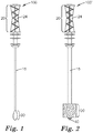
- FIG. 1 shows one embodiment of a sampling device that can be used in an apparatus and kit according to the present disclosure.
- the sampling device 100 comprises a handling portion 20 and a sampling portion 30.
- the sampling portion 30 is coupled to the handling portion 20 via an optional stem 15.
- the sampling device 100 is shaped and dimensioned to be received in a corresponding container (not shown).
- the handling portion 20 can be made from a variety of materials (e.g., wood, metal, plastic, glass) using processes known in the art and the handling portion 20 functions as a location at which the sampling device 100 can be grasped and/or manipulated during use.
- the handling portion comprises a handle 24 that is shaped and/or textured to facilitate manual or mechanical gripping of the sampling device 100.
- the sampling portion 30 includes fibrous materials or foam materials capable of obtaining (e.g., via contact, capillary pressure and/or absorption) and retaining a sample from a sample source.
- the sampling portion 30 can retain a liquid sample.
- the sampling portion may comprise an applicator shaft (e.g., a solid molded plastic applicator shaft) having a tip coated with short fibers (e.g., nylon fibers) that are arranged in a perpendicular fashion such as, for example, the flocked swabs described in U.S. Patent No. 8,114,027 .
- the sampling portion may comprise an applicator shaft (e.g., a solid molded plastic applicator shaft) having a tip coated with a fibrous material such as, for example, the sea-island bicomponent fibers (e.g., polyester/polyester conjugated fiber yarn or polyester/nylon conjugated fiber yarn) described in U.S. Patent Publication Nos. 2011/0262951 and 2011/0262952 .
- an applicator shaft e.g., a solid molded plastic applicator shaft
- a fibrous material such as, for example, the sea-island bicomponent fibers (e.g., polyester/polyester conjugated fiber yarn or polyester/nylon conjugated fiber yarn) described in U.S. Patent Publication Nos. 2011/0262951 and 2011/0262952 .
- the liquid sample comprises a liquid sample having a predetermined maximum sample volume.
- the sampling portion 30 is adapted to obtain and retain a predetermined volume of sample by selecting fibrous or foam materials having the appropriate composition, dimensions, porosity, hydrophilicity and combinations thereof.
- the maximum sample volume may be selected, for example, based on the desired sensitivity of the test performed with the sample.
- the sampling portion may obtain (e.g., via contact capillary pressure and/or absorption) and retain residue (e.g., liquid and/or solid residue) from a surface.
- sampling portion 30 is comprised of a material that achieves the desired sample acquisition characteristics, which may depend upon the type of sample acquired (e.g., some liquid samples may include dissolved or suspended solids that affect the surface tension of the liquid).
- Material properties that may affect the ability of sampling portion 30 to acquire and retain a sample include, for example, surface energy.
- the material may be selected to have a particular surface energy in order to draw the sample by capillary force or absorption, for example, into one or more spaces between the plurality of fibers disposed in the sampling portion 30.
- sampling portion may include substantial inertness relative to the sample or a relatively low rate of elution of chemicals or other contaminants that may affect luciferase enzyme activity, e.g., when the sample is released from sampling portion 30.
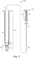
- FIG. 2 shows a sampling device 100' comprising a sampling portion 30 that comprises a foam material.
- the foam material comprises individual cells or void spaces that are capable of obtaining and retaining a liquid sample.
- Sampling devices of the present disclosure may comprise a sampling portion that includes a foam material.
- Suitable foam materials for use in a sampling device of the present disclosure include, for example, polyurethane foams, polyethylene foams, and polystyrene foams.
- the foams may be treated (e.g., corona-treated or electron beam-treated) in order to make the surface of the polymer more hydrophilic.
- the foam material can be coupled to a stem 15 and/or a handling portion 20 using materials (e.g., adhesives, mechanical fasteners, or the like) and processes known in the art.
- the sampling device 100 further can comprise a piercing tip 40.
- any sampling device according to the present disclosure further may comprise a coating area (not shown) on which a coating comprising a pH-adjusting reagent according to the present disclosure can be disposed.
- the coating area may be located, for example, on a portion of the stem and/or the optional piercing tip of the sampling device.
- a sampling device of the present disclosure comprises a dry coating.
- the dry coating can be disposed on and/or in (e.g., in the interstitial spaces between fibers of a fibrous material or in the individual cells of a foam material) the sampling portion of the device so that, when the device is dipped into the liquid sample, the coating is contacted with the liquid sample.
- the dry coating includes an effective amount of a pH-adjusting reagent that, when contacted with a liquid reagent composition of the present disclosure, changes the pH of the liquid reagent composition having an initial pH of about 6.8 or lower to an adjusted pH of about 6.9 or higher.
- the pH-adjusting reagent comprises a water-soluble reagent.
- the pH-adjusting reagent comprises a buffer component (e.g., N-[2-hydroxyethyl] piperazine-N'-[2-ethanesulfonic acid] (HEPES), N-[tris(hydroxymethyl)methyl]glycine (TRICINE), and combinations thereof).
- the pH-adjusting reagent does not comprise an effective amount of a buffer component comprising phosphate.
- a buffer component comprising an amount of phosphate effective to change the pH of the liquid reagent composition from an initial pH 6.8 or lower to an adjusted pH of 6.9 or higher may also be sufficient to at least partially inhibit luciferase enzyme activity.
- the pH-adjusting reagent further comprises a metallic base (e.g., sodium hydroxide, potassium hydroxide).
- the coating further can comprise a cell lysis agent that does not substantially inhibit luciferase enzyme activity.
- suitable cell lysis agents include, but are not limited to, chlorhexidine digluconate, TRITON X-100, lysozyme, lysostaphin, bacteriophage lysin, a quaternary ammonium compound (e.g., benzalkonium chloride, benzethonium chloride), cetyl trimethylammonium chloride (CTAB), dodecyltrimethylammonium chloride (DTAB), TWEEN 20, TWEEN 80, and a combination of any two or more of the foregoing.
- CAB cetyl trimethylammonium chloride
- DTAB dodecyltrimethylammonium chloride
- the amount of pH-adjusting reagent coated onto the sampling device should be enough to change the pH of the liquid reagent composition from an initial (i.e., before contact with the pH-adjusting reagent) pH of 6.8 or lower to an adjusted pH of 7.2 to 8.0.
- a non-limiting example of a coating solution that can be used to prepare sampling devices of the present disclosure is shown in Table 1.
- the coating can be applied to the sampling device using any suitable coating method.
- the coating initially can be applied to the sampling device as a liquid coating (i.e., the pH-adjusting reagent is dissolved or suspended in a solvent such as water, for example).
- the solvent is subsequently dried to leave the substantially dry pH-adjusting reagent coated on the sampling device.
- the liquid coating is applied by dipping the sampling device (e.g., the sampling portion of the sampling device) into a liquid comprising the pH-adjusting reagent. While immersed in the coating liquid, the sampling device can be agitated to facilitate movement of the coating liquid into the one or more cavity of the sampling portion.
- the coated portion can be dried (e.g., in a stream of air, a convection oven, or the like) under conditions (e.g., ambient or above-ambient (warm) temperatures) sufficient to evaporate the solvent without substantially degrading the pH-adjusting reagent and/or cell lysis agent.
- conditions e.g., ambient or above-ambient (warm) temperatures
- the coating can be applied to the sampling device as a liquid coating and held in a substantially liquid state (e.g., by packaging the device in a sealed container made from substantially moisture-resistant material) until use.
- the liquid coating can comprise a humectant (e.g., propylene glycol) at a concentration that substantially does not leave a perdurable residue on a surface, as described in International Publication No. WO 2009/140356.
- the humectant comprises about 1 weight percent to about 50 weight percent of the liquid coating.
- the humectant comprises about 2 weight percent to about 10 weight percent of the liquid coating.
- Sampling devices having a liquid coating may be used in any kit of the present disclosure.
- Kits and apparatuses of the present disclosure further comprise a container.
- the container functions as a vessel in which to contact a sample with the liquid reagent composition described herein.
- the container comprises an opening and is configured (e.g., shaped and dimensioned) to receive at least a portion (e.g., the sampling portion) of the sampling device.
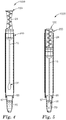
- FIG. 3 shows an exploded view, partially in section, of one embodiment of an apparatus comprising a container according to the present disclosure.
- the apparatus 1000 comprises a sampling device 100 comprising a handling portion 20 with a handle 24 and a sampling portion 30 according to any of the embodiments described herein.
- the apparatus 1000 further comprises a container 200, shown in cross-section in FIG. 3 .
- the container comprises at least one wall 50 and an opening 52, the opening configured to receive the sampling device 100.
- the apparatus 1000 with the opening 52 shown in the illustrated embodiment of FIG. 3 is shaped and dimensioned to receive the entire sampling device 100.
- the container further comprises a cuvette portion 54 that is adapted to be operationally coupled to a luminometer.
- the cuvette portion 54 is operationally coupled to a luminometer by placing the cuvette portion 54 of the container 200, or the entire container 200, into a complementary-shaped receiving compartment of the luminometer.
- the cuvette portion 54 is fabricated from optically-transmissible material (e.g., glass or a polymeric material such as polyethylene, polypropylene, polycarbonate, or polystyrene, for example) that permits the transmission there through of light emitted as a product of a reaction catalyzed by luciferase enzyme.
- optically-transmissible material e.g., glass or a polymeric material such as polyethylene, polypropylene, polycarbonate, or polystyrene, for example
- the container 200 may be fabricated as a unitary article (not shown), for example, using extrusion and/or molding processes known in the art.
- portions of the container 200 such as the cylindrically-shaped sleeve 56 and the cuvette 55 of the illustrated embodiment of FIG. 3 , may be fabricated separately and coupled together using suitable means (e.g., an adhesive, a heat sealing process, a sonic weld, and/or by press-fitting the sleeve 56 and cuvette 55 together).
- suitable means e.g., an adhesive, a heat sealing process, a sonic weld, and/or by press-fitting the sleeve 56 and cuvette 55 together.
- the sleeve 56 may be fabricated via a molding or extrusion process, for example, using a plastic polymer such as polypropylene or polyethylene, for example.
- the cuvette 55 can be formed in a variety of geometric shapes, such as cubic, cuboid, cylindrical, conical, frusto-conical, other suitable geometric shapes, and combinations thereof.
- the walls of the cuvette 55 are configured to allow the passage of light (e.g., visible light) into and/or out of the cuvette 55.
- the container further may comprise a lamina 60.
- the lamina 60 can hold the cuvette 55 firmly together with the sleeve 56.
- the lamina 60 can be made from paper or a plastic film, for example, and may be used as a label.
- Kits and apparatuses of the present disclosure further comprise a liquid reagent composition (liquid reagent composition 70 shown in FIGS. 3-5 ).
- the liquid reagent composition comprises luciferin at a concentration (e.g., 0.3-0.4 mg/L luciferin) sufficient to facilitate a light-emitting reaction in the presence of luciferase; preferably, a glow-type luciferase; and a source of ATP.
- the source of ATP can be a sample as disclosed herein or a solution containing a predefined amount or concentration of ATP (i.e., a positive control or an ATP standard).
- the liquid reagent composition can comprise an aqueous solution.
- liquid reagent composition used in the apparatus or kit of the present disclosure has an initial (i.e., before contact with the pH-adjusting reagent) pH of 6.8 or lower.
- liquid reagent composition has an initial (i.e., before contact with the pH-adjusting reagent) pH of 6.4 or lower.
- a non-limiting example of a liquid composition according to the present disclosure is listed in Table 2 of the Examples.
- the liquid reagent composition optionally may comprise a buffering agent.
- Suitable buffering agents have a pKa that is effective to maintain the pH of the liquid reagent composition at a pH of 6.8 or lower, preferably at a pH of 6.4 or lower.
- N-(2-acetamido)-iminodiacetic acid (ADA) is a nonlimiting example of a suitable buffering agent.
- the buffering agent should be present in the liquid reagent composition in an amount (e.g., about 16 mM ADA in 425 microliters of liquid reagent composition at pH 6.4-6.8) that is high enough to effectively maintain the pH of the liquid reagent composition, yet low enough so that it does not substantially resist a change in the pH of the liquid reagent composition mediated by the pH-adjusting reagent coated on the sampling portion of the sampling device.
- the liquid reagent composition further comprises a luciferase enzyme.
- the luciferase enzyme can consist essentially of a recombinant luciferase enzyme having luciferase activity that is less sensitive to variations in temperature, ionic detergents, and reducing agents than a corresponding non-recombinant luciferase enzyme.
- the luciferase enzyme can be present in the liquid reagent composition at a concentration of about 9 mg/L, for example.
- the liquid reagent composition further can comprise a source of magnesium ions (e.g., magnesium diacetate tetrahydrate).
- the source of magnesium ions can be present at a concentration (e.g., about 3 mM, for example) that does not substantially interfere with luciferase enzyme activity when the liquid reagent composition is mixed with the liquid sample.
- the liquid reagent composition further can comprise a protein (e.g., bovine serum albumin).
- the protein may stabilize the luciferase enzyme during prolonged storage and/or make the luciferase enzyme less susceptible to protease enzyme activities.
- the protein should not substantially interfere with luciferase enzyme activity when the liquid reagent composition is mixed with the liquid sample.
- the protein may be present in the liquid reagent composition at a concentration of about 0.046 weight percent, for example.
- the liquid reagent composition further can comprise a preservative (e.g., 0.046 weight percent sodium azide) at a concentration that does not substantially interfere with luciferase enzyme activity when the liquid reagent composition is mixed with the liquid sample.
- the liquid reagent composition further may comprise ethylenediamine tetraacetic acid (EDTA).
- EDTA ethylenediamine tetraacetic acid
- the EDTA can act as a preservative in the liquid reagent composition and may also function to chelate ions present in the liquid reagent composition and/or the liquid sample.
- the liquid reagent composition can be disposed in a closed compartment.
- the closed compartment comprises a frangible wall.
- the container further comprises a liquid-resistant frangible wall 65disposed proximate the cuvette 55 that forms a compartment 67.
- the frangible wall 65 can be made from a water-resistant material, such as plastic film, metal foil, or a metal-coated plastic film, for example.
- the frangible wall 65 can be coupled to the cuvette 55 and/or the sleeve 56 via an adhesive, a heat seal, a sonic weld, or other means known in the art to form a liquid-resistant seal to retain the liquid reagent composition 70 in the compartment 67.
- the liquid reagent composition may be disposed in a frangible ampoule (e.g., a glass or polymeric ampoule) which is disposed in the container.
- the liquid reagent composition can be released from the frangible ampoule by squeezing the container with enough force to fracture the ampoule or by urging the sampling device (e.g., the piercing tip of the sampling device) against the ampoule with enough force to fracture the ampoule.
- the liquid reagent composition may be disposed in a compartment disposed in the sampling device.
- Nason U.S. Patent No. 5,266,266
- a swab device comprising a hollow stem and a liquid-containing closed compartment with an actuatable valve (break-off nib) that releases the liquid into the hollow stem for delivery into tube in which at least a portion of the swab is disposed.
- Any sampling device of the present disclosure may be modified to include the hollow stem and reagent chamber of Nason.
- the reagent chamber can contain the liquid reagent composition of the present disclosure and the liquid reagent composition can be transferred into the container of the present disclosure using the technique described by Nason.
- the liquid reagent composition can be transferred to the container before or after the liquid sample is acquired using the sampling device according to the present disclosure.
- Other compartments for temporarily storing liquid reagent compositions to be used in a reaction are known in the art and a person of ordinary skill in the art will recognize such compartments can be used to temporarily contain the liquid reagent composition of the present disclosure.
- Non-limiting examples of such compartments can be found in U.S. Patent No. 7,399,984 ; U.S. Patent No. 6,548,018 ; U.S. Patent No. 5,965,453 ; and U.S. Patent No. 6,524,530 .
- the present disclosure provides a kit.
- the kit may be used, for example, to detect a presence or absence of ATP in a liquid sample according the method described herein.
- the kit may comprise instructions disclosing an embodiment of the method disclosed herein.
- Kits of the present disclosure comprise the apparatus of the invention, i. e. comprising. a container according to any of the embodiments disclosed herein.
- the container comprises an opening and a cuvette portion that is adapted to be operationally coupled to a luminometer.
- Kits of the present disclosure further comprise a liquid reagent composition comprising luciferin according to any of the embodiments disclosed herein.
- the initial pH (i.e., before contact with a pH-adjusting reagent of the present disclosure) of the liquid reagent composition is pH 6.8 or lower; preferably, pH 6.4 or lower.
- Kits of the present disclosure further comprise a sampling device having a sampling portion and a handling portion according to any of the embodiments disclosed herein.
- the liquid reagent composition is disposed in a closed compartment disposed in the container or the sampling device, as disclosed herein.
- the sampling portion of the sampling device comprises fibrous materials or foam materials and is configured to obtain (e.g., via capillary pressure or absorption) and retain a predetermined volume of liquid sample from a sample source.
- the sampling portion of the sampling device comprises a dry coating that includes an effective amount of a pH-adjusting reagent that, when contacted (e.g., mixed) with the liquid reagent composition, changes the pH of the liquid reagent composition to pH 7.2 - 8.0, more preferably to about pH 7.2 - 7.8.
- the pH-adjusting reagent comprises a water-soluble reagent.
- Kits and apparatuses of the present disclosure can be used methods of detecting a presence or an absence of ATP in a liquid sample.
- the presence of ATP in a sample can indicate a possible presence of organic residues and/or microorganisms (e.g., pathogenic microorganisms) in the sample.
- the quantity of ATP in the sample can be an indicator of the relative number of microorganisms in the sample.
- a sampling device is used to obtain a liquid sample which is subsequently tested to detect a presence or an absence of ATP in the liquid sample. Because the amount of ATP in a sample can be an indicator of the cleanliness of the sample and/or the presence of microorganisms in the sample, it may be desirable to calculate the absolute or relative quantity of ATP in the sample. Therefore, it is desirable to test a predetermined volume of sample, so that the amount of ATP per unit volume of sample can be determined.
- the amount of ATP per unit volume of sample can be compared to a predetermined value to determine whether the sample is acceptable for use in a particular application (e.g., food or beverage production), whether a cleaning process has been effective in removing organic residues, and/or whether a biocide treatment has been effective in reducing the number of microorganisms.
- a particular application e.g., food or beverage production
- a cleaning process has been effective in removing organic residues
- biocide treatment has been effective in reducing the number of microorganisms.
- a first method described herein comprises using a sampling device to obtain a predetermined volume of liquid sample, contacting the predetermined volume of sample with a liquid reagent composition in a container to form a reaction mixture, and using a luminometer to detect light emitted from the reaction mixture.
- the predetermined volume of liquid sample can be about 10 microliters to about 250 microliters. In some embodiments, the predetermined volume of liquid sample can be about 100 microliters to about 200 microliters. In some embodiments, the predetermined volume of liquid sample can be about 125 microliters to about 175 microliters.
- the sample comprises a liquid.
- the liquid may comprise water.
- the sample further may comprise solids that are dissolved, dispersed, and/or suspended in the liquid.
- suitable samples include clean-in-place (CIP) rinse-water samples, process and cooling water samples, and endoscope rinse water samples.
- the sampling device used in the first method described herein can be any sampling device disclosed herein.
- the sampling device comprises a sampling portion and a handling portion.
- the sampling portion is adapted to acquire and releasably retain a predetermined volume of liquid sample.
- the sampling portion includes fibrous materials or foam materials capable of obtaining (e.g., via capillary pressure or absorption) and retaining a liquid sample from a sample source.
- the sampling portion retains a predetermined maximum sample volume.
- the sampling portion of the device comprises a dry coating that includes an effective amount of a pH-adjusting reagent that, when contacted (e.g., mixed) with a liquid reagent composition having an initial pH of 6.8 or lower (i.e., before contacting the pH-adjusting reagent), adjusts the pH of the liquid reagent composition to 6.9 or higher.
- the sampling portion of the device comprises a moist (i.e., liquid) coating that includes an effective amount of a pH-adjusting reagent that, when contacted with a liquid reagent composition having an initial pH of 6.8 or lower, adjusts the pH of the liquid reagent composition to 6.9 or higher.
- the second method is used to detect ATP that is present in residue on a surface (e.g., liquid and/or solid residue found on a solid surface.
- the second method is particularly useful, for example, to detect the efficacy of a process that is used to clean the surface. In many environments (e.g., food-processing facilities, hospitals), a cleaning process should substantially reduce or remove detectable ATP from the surface that is to be tested.
- Suitable samples for the second method described herein include, but are not limited to, processing equipment (e.g., food-handling surfaces, tubes, drains, conveyors, storage containers), environmental surfaces (e.g., sinks, countertops, drawers, floors, walls, ceilings, doors, bedrails, linens, computer touch screens, keyboards, monitors), and medical equipment or devices (e.g., endoscopes, retractors, trocars, scalpels, trays).
- processing equipment e.g., food-handling surfaces, tubes, drains, conveyors, storage containers
- environmental surfaces e.g., sinks, countertops, drawers, floors, walls, ceilings, doors, bedrails, linens, computer touch screens, keyboards, monitors
- medical equipment or devices e.g., endoscopes, retractors, trocars, scalpels, trays.
- the sample may comprise liquid and/or solid residue present on a surface.
- the sampling device used in the second method described herein can be any sampling device disclosed herein.
- the sampling device comprises a sampling portion and a handling portion.
- the sampling portion is adapted to acquire a sample of surface residue.
- the sampling portion includes fibrous materials or foam materials capable of obtaining and retaining the surface residue.
- the sampling portion of the device comprises a dry coating that includes an effective amount of a pH-adjusting reagent that, when contacted with a liquid reagent composition having an initial pH of 6.8 or lower, adjusts the pH of the liquid reagent composition to 6.9 or higher.
- the sampling portion of the device comprises a moist (i.e., liquid) coating that includes an effective amount of a pH-adjusting reagent that, when contacted with a liquid reagent composition having an initial pH of 6.8 or lower, adjusts the pH of the liquid reagent composition to 6.9 or higher.
- the liquid reagent composition used in any embodiment of the first or second method described herein comprises a luciferin (e.g., firefly luciferin).
- Luciferin is a compound that undergoes oxidation by luciferase enzyme activity to produce oxyluciferin and light. Luciferin compounds can be unstable when stored for extended periods of time in liquid solutions at a pH above 6.8.
- the liquid reagent composition used in the method of the present disclosure has an initial pH of 6.8 or lower.
- liquid reagent composition has an initial pH of 6.4 or lower.
- the liquid reagent composition further comprises a luciferase enzyme.
- the luciferase enzyme comprises a recombinant luciferase enzyme having luciferase activity that is less sensitive than a corresponding non-recombinant luciferase enzyme to variations in temperature, ionic detergents, and reducing agents.
- the luciferase enzyme consists essentially of a recombinant luciferase enzyme having luciferase activity that is less sensitive to variations in temperature, ionic detergents, and reducing agents than a corresponding non-recombinant luciferase enzyme.
- the liquid reagent composition optionally may comprise a buffering agent.
- the buffering agent can be used to maintain the liquid reagent composition at an initial pH (e.g., ⁇ 6.8) that is suitable to store a liquid solution containing luciferin.
- N-(2-acetamido)-iminodiacetic acid (ADA) is a nonlimiting example of a suitable buffering agent.
- the buffering agent should be present in the liquid reagent composition in an amount (e.g., about 16 mM ADA in 425 microliters of liquid reagent composition at pH 6.4-6.8) that is high enough to effectively maintain the pH of the liquid reagent composition, yet low enough so that it does not substantially resist a change in the pH of the liquid reagent composition mediated by the pH-adjusting reagent coated on the sampling portion of the sampling device.
- an amount e.g., about 16 mM ADA in 425 microliters of liquid reagent composition at pH 6.4-6.
- the container used in any embodiment of the first or second method described herein comprises a cuvette portion.
- the cuvette portion permits the transmission there through of light emitted as a product of the reaction catalyzed by luciferase enzyme.
- the cuvette portion is adapted (e.g., shaped and dimensioned) to be operationally coupled to the luminometer.
- using a luminometer to detect light emitted from the reaction mixture comprises detecting a presence or an absence of ATP in the liquid sample.
- using a luminometer to detect light emitted from the reaction mixture comprises measuring a quantity (e.g., a relative quantity or an absolute quantity) of ATP present in the liquid sample.
- contacting the predetermined volume of sample with a liquid reagent composition in a container to form a reaction mixture comprises bringing the sampling portion of the sampling device into contact with the liquid reagent composition in a container.
- the contact may be achieved, for example, by immersing at least a part; preferably, the entire sampling portion; of the sampling device in the liquid reagent composition.
- the contact forms a reaction mixture (e.g., by diffusion of at least part of the liquid sample into the liquid reagent composition).
- luciferase can be added to the reaction mixture.
- the ATP can facilitate a light-emitting reaction catalyzed by luciferase enzyme.
- the light-emitting reaction can be detected in the aforementioned luminometer.
- FIGS. 4 and 5 illustrate one embodiment of a process of contacting a predetermined volume of sample with a liquid reagent composition in a container to form a reaction mixture.
- the sampling device is inserted into the container 200.
- FIG. 4 shows the sampling device 100 with the stem 15 and sampling portion 30 in the container.
- the sampling device 100 and container 200 are disposed in a first operational position with respect to one another and the apparatus 1000 is ready to bring the sample into contact with the liquid reagent composition 70 located in the compartment 67.
- the sampling portion 30 is urged toward the compartment 67 until it ruptures the frangible wall 65 and brings the liquid sample (not shown) associated with the sampling portion 30 into contact with the liquid reagent composition 70, as shown in FIG. 5 .
- the sampling device 100 and container 200 are disposed in a second operational position with respect to each other. In this embodiment, the sampling device 100 is fully-inserted into the container 200 and the sampling portion 30 of the sampling device is contacting the liquid reagent composition 70.
- contacting the predetermined volume of sample with a liquid reagent composition in a container to form a reaction mixture further can comprise the step of agitating the sample and the liquid reagent composition in the container. This may be done manually or mechanically, for example, by rapidly shaking the container in a swirling motion, a pendulum-like motion, or by contacting the container with a machine that vibrates the container.
- the cuvette portion of the container is operationally coupled to the luminometer in order to detect the light emission resulting from luciferase enzyme activity.
- the luminometer Commercially-available luminometers are suitable for use in any embodiment of the method described herein.
- a non-limiting example of a suitable luminometer is the3MTM Clean-TraceTM NG Luminometer commercially available from 3M Company, St. Paul, MN.
- the cuvette is operationally coupled by placing a portion (e.g., the cuvette portion) of the container or the entire container into a corresponding receiving compartment of the luminometer.
- the cuvette portion may be operationally coupled to the luminometer before or after forming the reaction mixture.
- the cuvette portion is operationally coupled to the luminometer after the reaction mix is formed. In some embodiments the cuvette portion is operationally coupled to the luminometer up to 5 seconds after forming the reaction mixture. In some embodiments the cuvette portion is operationally coupled to the luminometer up to 10 seconds after forming the reaction mixture. In some embodiments the cuvette portion is operationally coupled to the luminometer up to 15 seconds after forming the reaction mixture. In some embodiments the cuvette portion is operationally coupled to the luminometer up to 20 seconds after forming the reaction mixture. In some embodiments the cuvette portion is operationally coupled to the luminometer up to 30 seconds after forming the reaction mixture. In some embodiments the cuvette portion is operationally coupled to the luminometer up to 45 seconds after forming the reaction mixture.
- the cuvette portion is operationally coupled to the luminometer up to 60 seconds after forming the reaction mixture. In some embodiments the cuvette portion is operationally coupled to the luminometer up to 90 seconds after forming the reaction mixture. In some embodiments the cuvette portion is operationally coupled to the luminometer up to 2 minutes after forming the reaction mixture. Preferably, the cuvette is operationally coupled to the luminometer within about 5 to 10 seconds after forming the reaction mixture.
- the light-emission is monitored by the luminometer. After the reaction mixture is formed, it may take a period of time for the reaction to reach a relatively stable quantity of light emission.
- the liquid reagent composition comprises luciferin at a concentration (e.g., about 0.3-0.4 mg/L luciferin) sufficient to facilitate a light-emitting reaction in the presence of luciferase and a source of ATP.
- the source of ATP can be a liquid sample as disclosed herein or a solution containing a predefined amount or concentration of ATP (i.e., a positive control or an ATP standard).
- the liquid reagent composition can comprise an aqueous solution.
- the liquid reagent composition used in the apparatus or kit of the present disclosure has an initial pH of 6.8 or lower.
- liquid reagent composition has an initial pH of 6.4 or lower.
- the liquid reagent composition optionally may comprise a buffer component.
- Suitable buffer components have a pKa that is effective to maintain the initial pH of the liquid reagent composition at a pH of 6.8 or lower, preferably at a pH of 6.4 or lower.
- N-(2-acetamido)-iminodiacetic acid (ADA) is a nonlimiting example of a suitable buffering agent.
- the buffer component should be present in the liquid reagent composition in an amount (e.g., about 16 mM ADA in 425 microliters of liquid reagent composition at pH 6.4-6.8) that is high enough to effectively maintain the pH of the liquid reagent composition, yet low enough so that it does not substantially resist a change in the pH of the liquid reagent composition mediated by the pH-adjusting reagent coated on the sampling portion of the sampling device.
- the liquid reagent composition further may comprise a luciferase enzyme.
- the luciferase enzyme can consist essentially of a recombinant luciferase enzyme having luciferase activity that is less sensitive to variations in temperature, ionic detergents, and reducing agents than a corresponding non-recombinant luciferase enzyme.
- the luciferase enzyme can be present in the liquid reagent composition at a concentration of about 9 mg/L, for example.
- the liquid reagent composition further can comprise a source of magnesium ions (e.g., magnesium diacetate tetrahydrate).
- the source of magnesium ions can be present at a concentration (e.g., about 3 mM, for example) that does not substantially interfere with luciferase enzyme activity when the liquid reagent composition is mixed with the liquid sample.
- the liquid reagent composition further can comprise a protein (e.g., bovine serum albumin). The protein may be present in the liquid reagent composition at a concentration of about 0.046 weight percent, for example.
- the liquid reagent composition further can comprise a preservative (e.g., 0.046 weight percent sodium azide) at a concentration that does not substantially interfere with luciferase enzyme activity when the liquid reagent composition is mixed with the liquid sample.
- contacting the sampling device comprising the liquid sample with liquid reagent composition comprises contacting the sampling device with the liquid reagent composition at a particular temperature (e.g. ambient temperature).
- a particular temperature e.g. ambient temperature.
- contacting the sampling device comprising the liquid sample with liquid reagent composition comprises contacting the liquid sample with the liquid reagent composition at temperature within a range of 10° C and 35° C, inclusive.
- contacting the sampling device comprising the liquid sample with liquid reagent composition comprises contacting the liquid sample with the liquid reagent composition at temperature within a range of 15° C and 30° C, inclusive.
- a substantially steady-state amount of light is emitted from the composition after a period of time.
- the period of time may be affected by the temperature at which the contact occurs.
- a substantially steady-state amount of light is emitted from the composition in less than 25 seconds (e.g., when contact occurs at a temperature of about 10° C to about 20° C).
- a substantially steady-state amount of light is emitted from the composition in about 22 seconds or less (e.g., when contact occurs at a temperature of about 10° C to about 20° C).
- a substantially steady-state amount of light is emitted from the composition in less than 20 seconds (e.g., when contact occurs at a temperature of about 14° C to about 20° C). In some embodiments, a substantially steady-state amount of light is emitted from the composition in about 10 seconds or less (e.g., when contact occurs at a temperature of about 20° C).
- the methods of the present invention substantially reduces the amount of time necessary for a luciferase enzyme, in contact with a sample comprising ATP and a liquid reagent composition according to the present disclosure, to catalyze a light-emitting reaction that is substantially steady state.
- Coating Formulation 1 was prepared as a solution from the components listed in Table 1 and was used to coat the fibrous sampling portions of the sampling devices in Examples 1-5 and 8-12.
- the pH of Coating Formulation 1 was about 8.5.
- Table 1 Coating Formulation 1 Component Weight Percentage of Component in the Formulation Source Water (from a Milli Q water purification system) 96.33 % EMD Millipore Corp. (Billerica, MA) Chlorhexidine digluconate (20% in water) [CAS No. 18472-51-0] 0.32 % Sigma-Aldrich Co. (St. Louis, MO) Triton X100 [CAS No. 9002-93-1] 0.19 % Sigma-Aldrich Co. (St. Louis, MO) Tricine [CAS No. 5704-04-1] 1.72 % Sigma-Aldrich Co. (St. Louis, MO) Sodium Hydroxide (4N) 1.44 % VWR Corp. (Radnor, PA)
- the liquid reagent composition described herein comprises luciferin and a luciferase enzyme.
- the liquid reagent composition was prepared as a solution using the components listed in Table 2.
- the pH of the formulation was about 6.4.
- the total volume of liquid reagent composition contained in the sealed cuvette portion of each container of the present disclosure was about 425 microliters. Table 2.
- Liquid reagent composition Component Weight Percentage of Component in the Formulation Source Water (from a Milli Q water purification system) 77.6099 % EMD Millipore Corp. (Billerica, MA) ADA Free Acid [CAS No. 26239-55-4] 0.0283 % Sigma-Aldrich Co. (St. Louis, MO) ADA Disodium Salt [CAS No.
- Coating Formulation 2 was prepared as a solution from the components listed in Table 3 and was used to coat the fibrous sampling portions of the sampling devices in Comparative Examples 1-5 and 8-12.
- the pH of Coating Formulation 2 was about 7.2. Table 3.
- Coating Formulation 2 Component Weight Percentage of Component in the Formulation Source Water (from a Milli Q water purification system) 99.47 % EMD Millipore Corp. (Billerica, MA) Chlorhexidine digluconate (20% in water) [CAS No. 18472-51-0] 0.32 % Sigma-Aldrich Co. (St. Louis, MO) Triton X100 [CAS No. 9002-93-1] 0.21 % Sigma-Aldrich Co. (St. Louis, MO)
- the apparatus was prepared by combining components (sampling device component and container component) from two different commercially available products.
- the container component of the apparatus was obtained from a 3M Clean-TraceTM Water Plus-Total ATP Test Device (product number AQT200, 3M Company, St. Paul, MN).
- the sampling device component was removed from the device and discarded, while the container component was saved.
- the cuvette portion of the container contained the liquid reagent composition described in Table 2.
- the sampling device with a fibrous sampling portion was obtained from a 3M Clean-TraceTM Surface ATP Test Device (product number UXL-100, 3M Company, St. Paul, MN).
- the fibrous sampling portion was prepared from polyethylene terephthalate fibers.
- the sampling device component was removed from the test device and the rest of the test device (i.e. the container component) was discarded.
- the sampling device was then coated using Coating Formulation 1 (Table 1).
- the sampling device was coated by holding the handling portion of the sampling device and dipping the opposite end of the device into a vessel containing Coating Formulation 1 to a point where the entire fibrous sampling portion was immersed in the coating formulation for a period of 15 seconds.
- the sampling device was withdrawn from the coating formulation.
- Excess coating formulation was removed from the fibrous sampling portion by gently tapping the stem portion of the sampling device against the side of the container.
- the sampling device retained about 170 microliters of the formulation.
- the coated sampling device was immediately combined with the container portion of the 3M Clean-TraceTM Water Plus-Total ATP Test Device so that the sampling device and container were assembled in the first operational position with respect to each other ( FIG. 4 ).
- the ATP Test Apparatus 2 was prepared in the same manner as ATP Test Apparatus 1 except for the procedure used to coat the sampling device.
- the sampling device was coated by holding the handling portion of the sampling device and dipping the opposite end of the device into a vessel containing Coating Formulation 1 to a point where the entire fibrous sampling portion was immersed in the coating formulation for a period of 15 seconds.
- the sampling device was withdrawn from the coating formulation.
- Excess coating formulation was removed from the fibrous sampling portion by gently tapping the stem portion of the sampling device against the side of the container.
- the sampling device was then placed in a laminar flow cabinet and air dried at 20° C for a period of at least 3 hours. After the drying step, the coated sampling device was combined with the container portion of the 3M Clean-TraceTM Water Plus-Total ATP Test Device so that the sampling device and container were assembled in the first operational position with respect to each other ( FIG. 4 ).
- the ATP Test Apparatus 1 described above was used.
- the sampling device was removed from the ATP test apparatus and 10 microliters of a 1 ⁇ 10 -7 M aqueous solution of adenosine triphosphate (ATP) was added to the midsection of the fibrous sampling portion using a micropipette.
- the sampling device was reinserted into the container.
- the handle of the sampling device was pressed in order to move the sampling device from the first operational position to the second operational position.
- the movement of the sampling device in the container caused the frangible seal to be broken and the fibrous sampling portion to be positioned in direct contact with the liquid reagent composition.
- the container was held in the vertical position and shaken rapidly from side to side (pendulum motion) for about 5 seconds.
- the cuvette portion of the apparatus was immediately inserted into a 3M Clean-TraceTM NG Luminometer (commercially available from 3M Company, St. Paul, MN) and measurements were recorded in relative light units (RLU).
- RLU relative light units
- the RLU measurements were taken approximately every 10 seconds over a 70 second time period. This was accomplished by initiating a new reading for the luminometer immediately after the previous reading. Because the instrument takes approximately 10 seconds to obtain and present each new reading, this resulted in RLU measurements taken about every 10 seconds. All testing was conducted in an environmental chamber at 10° C. All materials and equipment were equilibrated in the chamber prior to testing. A total of five replicate samples were tested and the results are presented in Table 4.
- Movement of the sampling device from the first operational position to the second operational position resulted in the pH of the liquid reagent composition in the cuvette increasing from a pH of approximately 6.4 to a pH of approximately 7.2 to 7.6.
- Example 2 The same procedure was used as in Example 1 with the exception that the sampling device was coated with Coating Formulation 2 instead of Coating Formulation 1.
- the RLU measurements were taken every 10 seconds over a 70 second time period. A total of five replicate samples were tested and the results are presented in Table 5. Table 4.
- Example 6 The same procedure as described in Example 1 was followed with the exception that the tests were conducted at 15° C. A total of five replicate samples were tested and the results are presented in Table 6.
- Example 2 The same procedure was used as in Example 2 with the exception that the sampling device was coated with Coating Formulation 2, instead of Coating Formulation 1.
- the RLU measurements were taken every 10 seconds over a 70 second time period. A total of five replicate samples were tested and the results are presented in Table 7. Table 6.
- Example 8 The same procedure as described in Example 1 was followed with the exception that the tests were conducted at 20° C. A total of five replicate samples were tested and the results are presented in Table 8.
- Example 3 The same procedure was used as in Example 3 with the exception that the sampling device was coated with Coating Formulation 2, instead of Coating Formulation 1.
- the RLU measurements were taken every 10 seconds over a 70 second time period. A total of five replicate samples were tested and the results are presented in Table 9. Table 8.
- Example 1 The same procedure as described in Example 1 was followed with the exception that the tests were conducted at 25° C. A total of five replicate samples were tested and the results are presented in Table 10.
- Example 4 The same procedure was used as in Example 4 with the exception that the sampling device was coated with Coating Formulation 2, instead of Coating Formulation 1.
- the RLU measurements were taken every 10 seconds over a 70 second time period. A total of five replicate samples were tested and the results are presented in Table 11. Table 10.
- Example 12 The same procedure as described in Example 1 was followed with the exception that the tests were conducted at 30° C. A total of five replicate samples were tested and the results are presented in Table 12.
- Example 5 The same procedure was used as in Example 5 with the exception that the sampling device was coated with Coating Formulation 2, instead of Coating Formulation 1.
- the RLU measurements were taken every 10 seconds over a 70 second time period. A total of five replicate samples were tested and the results are presented in Table 13. Table 12.
- Example Number Mean Percent Increase in the RLU Measurement (n 5) Standard Deviation Example 1 10.7 5.5 Comparative Example 1 93.8 21.3
- Example 2 The same procedure as described in Example 1 was followed with the exception that ATP Test Apparatus 2 was used instead of ATP Test apparatus 1. A total of five replicate samples were tested and the results are presented in Table 16.
- Example 8 The same procedure was used as in Example 8 with the exception that the sampling device was coated with Coating Formulation 2, instead of Coating Formulation 1.
- the RLU measurements were taken every 10 seconds over a 70 second time period. A total of five replicate samples were tested and the results are presented in Table 17. Table 16.
- Example 8 The same procedure as described in Example 8 was followed with the exception that the tests were conducted at 15° C. A total of five replicate samples were tested and the results are presented in Table 18.
- Example 9 The same procedure was used as in Example 9 with the exception that the sampling device was coated with Coating Formulation 2, instead of Coating Formulation 1.
- the RLU measurements were taken every 10 seconds over a 70 second time period. A total of five replicate samples were tested and the results are presented in Table 19. Table 18.
- Example 8 The same procedure as described in Example 8 was followed with the exception that the tests were conducted at 20° C. A total of five replicate samples were tested and the results are presented in Table 20.
- Example 10 The same procedure was used as in Example 10 with the exception that the sampling device was coated with Coating Formulation 2, instead of Coating Formulation 1.
- the RLU measurements were taken every 10 seconds over a 70 second time period. A total of five replicate samples were tested and the results are presented in Table 21. Table 20.
- Example 8 The same procedure as described in Example 8 was followed with the exception that the tests were conducted at 25° C. A total of five replicate samples were tested and the results are presented in Table 22.
- Example 11 The same procedure was used as in Example 11 with the exception that the sampling device was coated with Coating Formulation 2, instead of Coating Formulation 1.
- the RLU measurements were taken every 10 seconds over a 70 second time period. A total of five replicate samples were tested and the results are presented in Table 23. Table 22.
- Example 8 The same procedure as described in Example 8 was followed with the exception that the tests were conducted at 30° C. A total of five replicate samples were tested and the results are presented in Table 24.
- Example 12 The same procedure was used as in Example 12 with the exception that the sampling device was coated with Coating Formulation 2, instead of Coating Formulation 1.
- the RLU measurements were taken every 10 seconds over a 70 second time period. A total of five replicate samples were tested and the results are presented in Table 25. Table 24.
Landscapes
- Chemical & Material Sciences (AREA)
- Organic Chemistry (AREA)
- Life Sciences & Earth Sciences (AREA)
- Zoology (AREA)
- Wood Science & Technology (AREA)
- Proteomics, Peptides & Aminoacids (AREA)
- Health & Medical Sciences (AREA)
- Engineering & Computer Science (AREA)
- Microbiology (AREA)
- Biochemistry (AREA)
- Physics & Mathematics (AREA)
- Molecular Biology (AREA)
- Biotechnology (AREA)
- Biophysics (AREA)
- Analytical Chemistry (AREA)
- Immunology (AREA)
- Bioinformatics & Cheminformatics (AREA)
- General Engineering & Computer Science (AREA)
- General Health & Medical Sciences (AREA)
- Genetics & Genomics (AREA)
- Measuring Or Testing Involving Enzymes Or Micro-Organisms (AREA)
- Apparatus Associated With Microorganisms And Enzymes (AREA)
- Sampling And Sample Adjustment (AREA)
Description
- Sampling programs are used to monitor critical raw materials, in-process materials, finished goods, and processing environments in the food and beverage industry. Routine sampling and testing can allow quality assurance personnel to detect undesirable materials,
such as microorganisms, at a very early stage and take steps to prevent subsequent contamination of equipment and/or products. A variety of tests can be performed to detect the unwanted materials. Examples of such tests include chemical residue tests (e.g., Adenosine triphosphate (ATP) bioluminescence tests and protein colorimetric tests), culture methods, genetic tests (e.g., PCR), immunodiagnostic tests, and bioluminescent tests. - Sample-collection devices typically are used to collect surface samples for environmental tests. Commercially-available sample-collection devices include absorbent devices such as sponges, swabs, and the like. In addition, certain sample-collection devices are capable of collecting a predetermined volume of a liquid sample.
- ATP is used routinely to detect a presence or absence of microorganisms in a sample. The chemical energy produced from the breakdown of ATP is converted into light energy. Each molecule of ATP consumed in the reaction produces one photon of light. This light output can be quantified in a luminometer. The presence of ATP in a sample may be a direct indicator of the presence of a microorganism (i.e., the ATP is derived from a microorganism) or the ATP may be an indirect indicator of the presence of a microorganism (i.e., the ATP is derived from vegetative or animal matter and indicates that nutrients that support the growth of microorganisms may be present in the sample). In addition, the presence or absence of ATP in a sample is used routinely to assess the efficacy of cleaning processes in food, beverage, other industrial processed, healthcare (e.g. endoscopes) and for such as cooling and process waters and/or to determine whether biocide treatment has been effective in reducing the level of microorganisms.
US2001/0046687 discloses a method for enhancing the luciferase activity in a chemiluminescence assay technique. - The present invention is in its broadest sense defined by the appended claims. In detail, the invention refers to an apparatus, comprising: a container with an opening and a cuvette portion that is adapted to be operationally coupled to a luminometer; a liquid reagent composition comprising luciferin and a luciferase enzyme, wherein the liquid reagent composition is disposed in a closed compartment, wherein the pH of the liquid reagent composition is 6.8 or lower; and a sampling device having a sampling portion; wherein the sampling portion is adapted to obtain a predetermined volume of liquid; wherein the sampling portion is adapted to acquire and releasably retain a sample; wherein the sampling portion comprises a fibrous or a foam material; wherein the sampling device comprises a dry coating disposed on and/or in the sampling portion of the sampling device; wherein the dry coating includes an effective amount of a pH-adjusting reagent that, when contacted with the liquid reagent composition having a pH of 6.8 or lower, changes the pH of the liquid reagent composition to 7.2-8.0; wherein the pH adjusting reagent comprises a water-soluble buffer component and a metallic base. In an embodiment, a kit comprises the apparatus. In any of the above embodiments of the kits or apparatuses, the pH-adjusting reagent can comprise a buffer component selected from the group consisting of N-[2-hydroxyethyl] piperazine-N'-[2-ethanesulfonic acid] (HEPES), N-[tris(hydroxymethyl)methyl]glycine (TRICINE), and combinations thereof. In any of the above embodiments of the kits or apparatuses, the coating further can comprise an effective amount of a cell extractant. In any of the above embodiments of the kits or methods, the luciferase enzyme can comprise or consist essentially of a recombinant luciferase enzyme having luciferase activity that is less sensitive to variations in temperature, ionic detergents, and reducing agents than a corresponding non-recombinant luciferase enzyme. In any of the above embodiments of the kits or apparatuses, the coating does not comprise an effective amount of a buffer component comprising phosphate
- The words "preferred" and "preferably" refer to embodiments of the invention that may afford certain benefits, under certain circumstances. However, other embodiments may also be preferred, under the same or other circumstances. Furthermore, the recitation of one or more preferred embodiments does not imply that other embodiments are not useful, and is not intended to exclude other embodiments from the scope of the invention.
- The terms "comprises" and variations thereof do not have a limiting meaning where these terms appear in the description and claims.
- As used herein, "a," "an," "the," "at least one," and "one or more" are used interchangeably. Thus, for example, a cell extractant can be interpreted to mean "one or more" cell extractants.
- The term "and/or" means one or all of the listed elements or a combination of any two or more of the listed elements.
- Also herein, the recitations of numerical ranges by endpoints include all numbers subsumed within that range (e.g., 1 to 5 includes 1, 1.5, 2, 2.75, 3, 3.80, 4, 5, etc.).
- The above summary of the present invention is not intended to describe each disclosed embodiment or every implementation of the present invention. The description that follows more particularly exemplifies illustrative embodiments. In several places throughout the application, guidance is provided through lists of examples, which examples can be used in various combinations. In each instance, the recited list serves only as a representative group and should not be interpreted as an exclusive list.
- Additional details of these and other embodiments are set forth in the accompanying drawings and the description below. Other features, objects and advantages will become apparent from the description and drawings, and from the claims.
-
-
FIG. 1 is a side view of one embodiment of a sampling device according to the present disclosure. -
FIG. 2 is a side view of an alternative embodiment of a sampling device according to the present disclosure. -
FIG. 3 is an exploded view, partially in section, of one embodiment of an apparatus according to the present disclosure. -
FIG. 4 is a side view, partially in section, of the assembled apparatus ofFIG. 3 showing the sampling device and the container in a first operational position with respect to each other. -
FIG. 5 is a side view, partially in section, of the assembled apparatus ofFIG. 3 showing the sampling device and the container in a second operational position with respect to each other. - Before any embodiments of the present disclosure are explained in detail, it is to be understood that the invention is not limited in its application to the details of construction and the arrangement of components set forth in the following description or illustrated in the following drawings. The invention is capable of other embodiments and of being practiced or of being carried out in various ways. Also, it is to be understood that the phraseology and terminology used herein is for the purpose of description and should not be regarded as limiting. The use of "including," "comprising," or "having" and variations thereof herein is meant to encompass the items listed thereafter and equivalents thereof as well as additional items. Unless specified or limited otherwise, the terms "connected" and "coupled" and variations thereof are used broadly and encompass both direct and indirect connections and couplings. Further, "connected" and "coupled" are not restricted to physical or mechanical connections or couplings. It is to be understood that other embodiments may be utilized and structural or logical changes may be made without departing from the scope of the present disclosure. Furthermore, terms such as "front," "rear," "top," "bottom," and the like are only used to describe elements as they relate to one another, but are in no way meant to recite specific orientations of the apparatus, to indicate or imply necessary or required orientations of the apparatus, or to specify how the invention described herein will be used, mounted, displayed, or positioned in use.
- The present disclosure generally relates to an apparatus for detecting ATP from organic residues and/or cells in a sample. According to the present disclosure, the ATP from cells is detected by contacting the sample with a cell extractant to release ATP and detecting the released ATP using an enzymatic reaction that involves the reaction of the released ATP with luciferase enzyme activity in the presence of luciferin and results in the production of measurable light.
- In particular, the present disclosure provides an apparatus and/or a kit with a sampling device that is adapted such that it 1) can acquire and releasably retain a predetermined volume of liquid sample, 2) can use the liquid sample to rehydrate an effective amount of dry, rehydratable pH-adjusting reagent, and 3) can deliver the liquid sample and effective amount of pH-adjusting reagent into a container in order to facilitate a luciferase-catalyzed light-emitting reaction. Advantageously, the present disclosure provides kits and apparatuses that can be used to store aqueous mixtures comprising luciferin for extended periods of time and instantly to adjust the pH of the mixtures in order to reduce the lag time required for a glow-type luciferase enzyme activity to achieve stable light output (e.g., maximum light output) in the presence of ATP and luciferin, particularly at lower temperatures (e.g., temperatures less than or equal to 20° C).
-
FIG. 1 shows one embodiment of a sampling device that can be used in an apparatus and kit according to the present disclosure. Thesampling device 100 comprises ahandling portion 20 and asampling portion 30. In the illustrated embodiment, thesampling portion 30 is coupled to thehandling portion 20 via anoptional stem 15. Typically, thesampling device 100 is shaped and dimensioned to be received in a corresponding container (not shown). The handlingportion 20 can be made from a variety of materials (e.g., wood, metal, plastic, glass) using processes known in the art and thehandling portion 20 functions as a location at which thesampling device 100 can be grasped and/or manipulated during use. Optionally, the handling portion comprises ahandle 24 that is shaped and/or textured to facilitate manual or mechanical gripping of thesampling device 100. - The
sampling portion 30 includes fibrous materials or foam materials capable of obtaining (e.g., via contact, capillary pressure and/or absorption) and retaining a sample from a sample source. In any embodiment, thesampling portion 30 can retain a liquid sample. In any embodiment, the sampling portion may comprise an applicator shaft (e.g., a solid molded plastic applicator shaft) having a tip coated with short fibers (e.g., nylon fibers) that are arranged in a perpendicular fashion such as, for example, the flocked swabs described inU.S. Patent No. 8,114,027 . In any embodiment, the sampling portion may comprise an applicator shaft (e.g., a solid molded plastic applicator shaft) having a tip coated with a fibrous material such as, for example, the sea-island bicomponent fibers (e.g., polyester/polyester conjugated fiber yarn or polyester/nylon conjugated fiber yarn) described inU.S. Patent Publication Nos. 2011/0262951 and2011/0262952 . - The liquid sample comprises a liquid sample having a predetermined maximum sample volume. The
sampling portion 30 is adapted to obtain and retain a predetermined volume of sample by selecting fibrous or foam materials having the appropriate composition, dimensions, porosity, hydrophilicity and combinations thereof. The maximum sample volume may be selected, for example, based on the desired sensitivity of the test performed with the sample. In any embodiment, the sampling portion may obtain (e.g., via contact capillary pressure and/or absorption) and retain residue (e.g., liquid and/or solid residue) from a surface. - In general,
sampling portion 30 is comprised of a material that achieves the desired sample acquisition characteristics, which may depend upon the type of sample acquired (e.g., some liquid samples may include dissolved or suspended solids that affect the surface tension of the liquid). Material properties that may affect the ability of samplingportion 30 to acquire and retain a sample include, for example, surface energy. For example, the material may be selected to have a particular surface energy in order to draw the sample by capillary force or absorption, for example, into one or more spaces between the plurality of fibers disposed in thesampling portion 30. Other characteristics of the material from which the sampling portion is made may include substantial inertness relative to the sample or a relatively low rate of elution of chemicals or other contaminants that may affect luciferase enzyme activity, e.g., when the sample is released from samplingportion 30. - Foam articles (e.g., sponges, sponges mounted on a handle) for obtaining samples from environmental surfaces are known in the art.
FIG. 2 shows a sampling device 100' comprising asampling portion 30 that comprises a foam material. The foam material comprises individual cells or void spaces that are capable of obtaining and retaining a liquid sample. Sampling devices of the present disclosure may comprise a sampling portion that includes a foam material. Suitable foam materials for use in a sampling device of the present disclosure include, for example, polyurethane foams, polyethylene foams, and polystyrene foams. In some embodiments, the foams may be treated (e.g., corona-treated or electron beam-treated) in order to make the surface of the polymer more hydrophilic. The foam material can be coupled to astem 15 and/or a handlingportion 20 using materials (e.g., adhesives, mechanical fasteners, or the like) and processes known in the art. Optionally, thesampling device 100 further can comprise a piercingtip 40. - Optionally, any sampling device according to the present disclosure further may comprise a coating area (not shown) on which a coating comprising a pH-adjusting reagent according to the present disclosure can be disposed. The coating area may be located, for example, on a portion of the stem and/or the optional piercing tip of the sampling device.
- A sampling device of the present disclosure comprises a dry coating. In any embodiment, the dry coating can be disposed on and/or in (e.g., in the interstitial spaces between fibers of a fibrous material or in the individual cells of a foam material) the sampling portion of the device so that, when the device is dipped into the liquid sample, the coating is contacted with the liquid sample. The dry coating includes an effective amount of a pH-adjusting reagent that, when contacted with a liquid reagent composition of the present disclosure, changes the pH of the liquid reagent composition having an initial pH of about 6.8 or lower to an adjusted pH of about 6.9 or higher. In any embodiment, the pH-adjusting reagent comprises a water-soluble reagent. In any embodiment, the pH-adjusting reagent comprises a buffer component (e.g., N-[2-hydroxyethyl] piperazine-N'-[2-ethanesulfonic acid] (HEPES), N-[tris(hydroxymethyl)methyl]glycine (TRICINE), and combinations thereof). In some embodiments, the pH-adjusting reagent does not comprise an effective amount of a buffer component comprising phosphate. A buffer component comprising an amount of phosphate effective to change the pH of the liquid reagent composition from an initial pH 6.8 or lower to an adjusted pH of 6.9 or higher may also be sufficient to at least partially inhibit luciferase enzyme activity. In any embodiment, the pH-adjusting reagent further comprises a metallic base (e.g., sodium hydroxide, potassium hydroxide).
- The coating further can comprise a cell lysis agent that does not substantially inhibit luciferase enzyme activity. Examples of suitable cell lysis agents include, but are not limited to, chlorhexidine digluconate, TRITON X-100, lysozyme, lysostaphin, bacteriophage lysin, a quaternary ammonium compound (e.g., benzalkonium chloride, benzethonium chloride), cetyl trimethylammonium chloride (CTAB), dodecyltrimethylammonium chloride (DTAB),
TWEEN 20, TWEEN 80, and a combination of any two or more of the foregoing. - The amount of pH-adjusting reagent coated onto the sampling device should be enough to change the pH of the liquid reagent composition from an initial (i.e., before contact with the pH-adjusting reagent) pH of 6.8 or lower to an adjusted pH of 7.2 to 8.0.
- A non-limiting example of a coating solution that can be used to prepare sampling devices of the present disclosure is shown in Table 1. The coating can be applied to the sampling device using any suitable coating method. In any embodiment, the coating initially can be applied to the sampling device as a liquid coating (i.e., the pH-adjusting reagent is dissolved or suspended in a solvent such as water, for example). The solvent is subsequently dried to leave the substantially dry pH-adjusting reagent coated on the sampling device. In any embodiment, the liquid coating is applied by dipping the sampling device (e.g., the sampling portion of the sampling device) into a liquid comprising the pH-adjusting reagent. While immersed in the coating liquid, the sampling device can be agitated to facilitate movement of the coating liquid into the one or more cavity of the sampling portion. After coating the device, the coated portion can be dried (e.g., in a stream of air, a convection oven, or the like) under conditions (e.g., ambient or above-ambient (warm) temperatures) sufficient to evaporate the solvent without substantially degrading the pH-adjusting reagent and/or cell lysis agent.
- As described herein, the coating can be applied to the sampling device as a liquid coating and held in a substantially liquid state (e.g., by packaging the device in a sealed container made from substantially moisture-resistant material) until use. Optionally, the liquid coating can comprise a humectant (e.g., propylene glycol) at a concentration that substantially does not leave a perdurable residue on a surface, as described in International Publication No. WO 2009/140356. In some embodiments, the humectant comprises about 1 weight percent to about 50 weight percent of the liquid coating. Preferably, the humectant comprises about 2 weight percent to about 10 weight percent of the liquid coating. Sampling devices having a liquid coating may be used in any kit of the present disclosure.
- Kits and apparatuses of the present disclosure further comprise a container. The container functions as a vessel in which to contact a sample with the liquid reagent composition described herein. The container comprises an opening and is configured (e.g., shaped and dimensioned) to receive at least a portion (e.g., the sampling portion) of the sampling device.
FIG. 3 shows an exploded view, partially in section, of one embodiment of an apparatus comprising a container according to the present disclosure. Theapparatus 1000 comprises asampling device 100 comprising a handlingportion 20 with ahandle 24 and asampling portion 30 according to any of the embodiments described herein. Theapparatus 1000 further comprises acontainer 200, shown in cross-section inFIG. 3 . - The container comprises at least one
wall 50 and anopening 52, the opening configured to receive thesampling device 100. As discussed below, theapparatus 1000 with theopening 52 shown in the illustrated embodiment ofFIG. 3 is shaped and dimensioned to receive theentire sampling device 100. The container further comprises acuvette portion 54 that is adapted to be operationally coupled to a luminometer. Typically, thecuvette portion 54 is operationally coupled to a luminometer by placing thecuvette portion 54 of thecontainer 200, or theentire container 200, into a complementary-shaped receiving compartment of the luminometer. Thecuvette portion 54 is fabricated from optically-transmissible material (e.g., glass or a polymeric material such as polyethylene, polypropylene, polycarbonate, or polystyrene, for example) that permits the transmission there through of light emitted as a product of a reaction catalyzed by luciferase enzyme. - The
container 200 may be fabricated as a unitary article (not shown), for example, using extrusion and/or molding processes known in the art. Alternatively, portions of thecontainer 200, such as the cylindrically-shapedsleeve 56 and thecuvette 55 of the illustrated embodiment ofFIG. 3 , may be fabricated separately and coupled together using suitable means (e.g., an adhesive, a heat sealing process, a sonic weld, and/or by press-fitting thesleeve 56 andcuvette 55 together). Thesleeve 56 may be fabricated via a molding or extrusion process, for example, using a plastic polymer such as polypropylene or polyethylene, for example. Thecuvette 55 can be formed in a variety of geometric shapes, such as cubic, cuboid, cylindrical, conical, frusto-conical, other suitable geometric shapes, and combinations thereof. Preferably, the walls of thecuvette 55 are configured to allow the passage of light (e.g., visible light) into and/or out of thecuvette 55. Optionally, the container further may comprise alamina 60. Thelamina 60 can hold thecuvette 55 firmly together with thesleeve 56. Thelamina 60 can be made from paper or a plastic film, for example, and may be used as a label. - Kits and apparatuses of the present disclosure further comprise a liquid reagent composition (
liquid reagent composition 70 shown inFIGS. 3-5 ). The liquid reagent composition comprises luciferin at a concentration (e.g., 0.3-0.4 mg/L luciferin) sufficient to facilitate a light-emitting reaction in the presence of luciferase; preferably, a glow-type luciferase; and a source of ATP. In a method of the present disclosure, the source of ATP can be a sample as disclosed herein or a solution containing a predefined amount or concentration of ATP (i.e., a positive control or an ATP standard). In any embodiment, the liquid reagent composition can comprise an aqueous solution. The liquid reagent composition used in the apparatus or kit of the present disclosure has an initial (i.e., before contact with the pH-adjusting reagent) pH of 6.8 or lower. Preferably, liquid reagent composition has an initial (i.e., before contact with the pH-adjusting reagent) pH of 6.4 or lower. - A non-limiting example of a liquid composition according to the present disclosure is listed in Table 2 of the Examples.
- In any embodiment of a kit or apparatus according to the present disclosure, the liquid reagent composition optionally may comprise a buffering agent. Suitable buffering agents have a pKa that is effective to maintain the pH of the liquid reagent composition at a pH of 6.8 or lower, preferably at a pH of 6.4 or lower. N-(2-acetamido)-iminodiacetic acid (ADA) is a nonlimiting example of a suitable buffering agent. The buffering agent should be present in the liquid reagent composition in an amount (e.g., about 16 mM ADA in 425 microliters of liquid reagent composition at pH 6.4-6.8) that is high enough to effectively maintain the pH of the liquid reagent composition, yet low enough so that it does not substantially resist a change in the pH of the liquid reagent composition mediated by the pH-adjusting reagent coated on the sampling portion of the sampling device. The liquid reagent composition further comprises a luciferase enzyme. In any embodiment, the luciferase enzyme can consist essentially of a recombinant luciferase enzyme having luciferase activity that is less sensitive to variations in temperature, ionic detergents, and reducing agents than a corresponding non-recombinant luciferase enzyme. The luciferase enzyme can be present in the liquid reagent composition at a concentration of about 9 mg/L, for example. In any embodiment, the liquid reagent composition further can comprise a source of magnesium ions (e.g., magnesium diacetate tetrahydrate). The source of magnesium ions can be present at a concentration (e.g., about 3 mM, for example) that does not substantially interfere with luciferase enzyme activity when the liquid reagent composition is mixed with the liquid sample. In any embodiment, the liquid reagent composition further can comprise a protein (e.g., bovine serum albumin). Without being bound by theory, the protein may stabilize the luciferase enzyme during prolonged storage and/or make the luciferase enzyme less susceptible to protease enzyme activities. At its working concentration, the protein should not substantially interfere with luciferase enzyme activity when the liquid reagent composition is mixed with the liquid sample. The protein may be present in the liquid reagent composition at a concentration of about 0.046 weight percent, for example. In any embodiment, the liquid reagent composition further can comprise a preservative (e.g., 0.046 weight percent sodium azide) at a concentration that does not substantially interfere with luciferase enzyme activity when the liquid reagent composition is mixed with the liquid sample. In any embodiment, the liquid reagent composition further may comprise ethylenediamine tetraacetic acid (EDTA). Without being bound by theory, the EDTA can act as a preservative in the liquid reagent composition and may also function to chelate ions present in the liquid reagent composition and/or the liquid sample.
- In any embodiment of a kit or apparatus according to the present disclosure, the liquid reagent composition can be disposed in a closed compartment. In some embodiments, the closed compartment comprises a frangible wall. In the illustrated embodiment of
FIG. 4 , the container further comprises a liquid-resistant frangible wall 65disposed proximate thecuvette 55 that forms acompartment 67. Thefrangible wall 65 can be made from a water-resistant material, such as plastic film, metal foil, or a metal-coated plastic film, for example. Thefrangible wall 65 can be coupled to thecuvette 55 and/or thesleeve 56 via an adhesive, a heat seal, a sonic weld, or other means known in the art to form a liquid-resistant seal to retain theliquid reagent composition 70 in thecompartment 67. - In an alternative embodiment (not shown) of a kit or apparatus according to the present disclosure, the liquid reagent composition may be disposed in a frangible ampoule (e.g., a glass or polymeric ampoule) which is disposed in the container. The liquid reagent composition can be released from the frangible ampoule by squeezing the container with enough force to fracture the ampoule or by urging the sampling device (e.g., the piercing tip of the sampling device) against the ampoule with enough force to fracture the ampoule.
- In yet another embodiment (not shown) of a kit or apparatus according to the present disclosure, the liquid reagent composition may be disposed in a compartment disposed in the sampling device.
Nason (U.S. Patent No. 5,266,266 ) discloses a swab device comprising a hollow stem and a liquid-containing closed compartment with an actuatable valve (break-off nib) that releases the liquid into the hollow stem for delivery into tube in which at least a portion of the swab is disposed. Any sampling device of the present disclosure may be modified to include the hollow stem and reagent chamber of Nason. The reagent chamber can contain the liquid reagent composition of the present disclosure and the liquid reagent composition can be transferred into the container of the present disclosure using the technique described by Nason. The liquid reagent composition can be transferred to the container before or after the liquid sample is acquired using the sampling device according to the present disclosure. Other compartments for temporarily storing liquid reagent compositions to be used in a reaction (e.g., a chemical and/or enzymatic reaction) are known in the art and a person of ordinary skill in the art will recognize such compartments can be used to temporarily contain the liquid reagent composition of the present disclosure. Non-limiting examples of such compartments can be found inU.S. Patent No. 7,399,984 ;U.S. Patent No. 6,548,018 ;U.S. Patent No. 5,965,453 ; andU.S. Patent No. 6,524,530 . - The present disclosure provides a kit. The kit may be used, for example, to detect a presence or absence of ATP in a liquid sample according the method described herein. The kit may comprise instructions disclosing an embodiment of the method disclosed herein.
- Kits of the present disclosure comprise the apparatus of the invention, i. e. comprising. a container according to any of the embodiments disclosed herein. The container comprises an opening and a cuvette portion that is adapted to be operationally coupled to a luminometer. Kits of the present disclosure further comprise a liquid reagent composition comprising luciferin according to any of the embodiments disclosed herein. The initial pH (i.e., before contact with a pH-adjusting reagent of the present disclosure) of the liquid reagent composition is pH 6.8 or lower; preferably, pH 6.4 or lower. Kits of the present disclosure further comprise a sampling device having a sampling portion and a handling portion according to any of the embodiments disclosed herein. The liquid reagent composition is disposed in a closed compartment disposed in the container or the sampling device, as disclosed herein. The sampling portion of the sampling device comprises fibrous materials or foam materials and is configured to obtain (e.g., via capillary pressure or absorption) and retain a predetermined volume of liquid sample from a sample source. The sampling portion of the sampling device comprises a dry coating that includes an effective amount of a pH-adjusting reagent that, when contacted (e.g., mixed) with the liquid reagent composition, changes the pH of the liquid reagent composition to pH 7.2 - 8.0, more preferably to about pH 7.2 - 7.8. In any embodiment, the pH-adjusting reagent comprises a water-soluble reagent.
- Kits and apparatuses of the present disclosure can be used methods of detecting a presence or an absence of ATP in a liquid sample. The presence of ATP in a sample can indicate a possible presence of organic residues and/or microorganisms (e.g., pathogenic microorganisms) in the sample. Moreover, the quantity of ATP in the sample can be an indicator of the relative number of microorganisms in the sample.
- In one method of the present disclosure, a sampling device is used to obtain a liquid sample which is subsequently tested to detect a presence or an absence of ATP in the liquid sample. Because the amount of ATP in a sample can be an indicator of the cleanliness of the sample and/or the presence of microorganisms in the sample, it may be desirable to calculate the absolute or relative quantity of ATP in the sample. Therefore, it is desirable to test a predetermined volume of sample, so that the amount of ATP per unit volume of sample can be determined. The amount of ATP per unit volume of sample can be compared to a predetermined value to determine whether the sample is acceptable for use in a particular application (e.g., food or beverage production), whether a cleaning process has been effective in removing organic residues, and/or whether a biocide treatment has been effective in reducing the number of microorganisms.
- Thus, a first method described herein comprises using a sampling device to obtain a predetermined volume of liquid sample, contacting the predetermined volume of sample with a liquid reagent composition in a container to form a reaction mixture, and using a luminometer to detect light emitted from the reaction mixture. The predetermined volume of liquid sample can be about 10 microliters to about 250 microliters. In some embodiments, the predetermined volume of liquid sample can be about 100 microliters to about 200 microliters. In some embodiments, the predetermined volume of liquid sample can be about 125 microliters to about 175 microliters.
- According to the first method described herein the sample comprises a liquid. The liquid may comprise water. The sample further may comprise solids that are dissolved, dispersed, and/or suspended in the liquid. Nonlimiting examples of suitable samples include clean-in-place (CIP) rinse-water samples, process and cooling water samples, and endoscope rinse water samples.
- The sampling device used in the first method described herein can be any sampling device disclosed herein. The sampling device comprises a sampling portion and a handling portion. The sampling portion is adapted to acquire and releasably retain a predetermined volume of liquid sample. The sampling portion includes fibrous materials or foam materials capable of obtaining (e.g., via capillary pressure or absorption) and retaining a liquid sample from a sample source. The sampling portion retains a predetermined maximum sample volume. In any embodiment of the first method, the sampling portion of the device comprises a dry coating that includes an effective amount of a pH-adjusting reagent that, when contacted (e.g., mixed) with a liquid reagent composition having an initial pH of 6.8 or lower (i.e., before contacting the pH-adjusting reagent), adjusts the pH of the liquid reagent composition to 6.9 or higher. In some embodiments of the first method, the sampling portion of the device comprises a moist (i.e., liquid) coating that includes an effective amount of a pH-adjusting reagent that, when contacted with a liquid reagent composition having an initial pH of 6.8 or lower, adjusts the pH of the liquid reagent composition to 6.9 or higher.
- Further described is a second method of detecting ATP in a sample. The second method is used to detect ATP that is present in residue on a surface (e.g., liquid and/or solid residue found on a solid surface. The second method is particularly useful, for example, to detect the efficacy of a process that is used to clean the surface. In many environments (e.g., food-processing facilities, hospitals), a cleaning process should substantially reduce or remove detectable ATP from the surface that is to be tested. Suitable samples for the second method described herein include, but are not limited to, processing equipment (e.g., food-handling surfaces, tubes, drains, conveyors, storage containers), environmental surfaces (e.g., sinks, countertops, drawers, floors, walls, ceilings, doors, bedrails, linens, computer touch screens, keyboards, monitors), and medical equipment or devices (e.g., endoscopes, retractors, trocars, scalpels, trays). According to the second method of the present disclosure, the sample may comprise liquid and/or solid residue present on a surface.
- The sampling device used in the second method described herein can be any sampling device disclosed herein. The sampling device comprises a sampling portion and a handling portion. The sampling portion is adapted to acquire a sample of surface residue. The sampling portion includes fibrous materials or foam materials capable of obtaining and retaining the surface residue. In any embodiment of the second method, the sampling portion of the device comprises a dry coating that includes an effective amount of a pH-adjusting reagent that, when contacted with a liquid reagent composition having an initial pH of 6.8 or lower, adjusts the pH of the liquid reagent composition to 6.9 or higher. In some embodiments of the second method, the sampling portion of the device comprises a moist (i.e., liquid) coating that includes an effective amount of a pH-adjusting reagent that, when contacted with a liquid reagent composition having an initial pH of 6.8 or lower, adjusts the pH of the liquid reagent composition to 6.9 or higher.
- The liquid reagent composition used in any embodiment of the first or second method described herein comprises a luciferin (e.g., firefly luciferin). Luciferin is a compound that undergoes oxidation by luciferase enzyme activity to produce oxyluciferin and light. Luciferin compounds can be unstable when stored for extended periods of time in liquid solutions at a pH above 6.8. Thus, the liquid reagent composition used in the method of the present disclosure has an initial pH of 6.8 or lower. Preferably, liquid reagent composition has an initial pH of 6.4 or lower.
- The liquid reagent composition further comprises a luciferase enzyme. In a preferred embodiment, the luciferase enzyme comprises a recombinant luciferase enzyme having luciferase activity that is less sensitive than a corresponding non-recombinant luciferase enzyme to variations in temperature, ionic detergents, and reducing agents. In some embodiments, the luciferase enzyme consists essentially of a recombinant luciferase enzyme having luciferase activity that is less sensitive to variations in temperature, ionic detergents, and reducing agents than a corresponding non-recombinant luciferase enzyme.
- In any embodiment, the liquid reagent composition optionally may comprise a buffering agent. The buffering agent can be used to maintain the liquid reagent composition at an initial pH (e.g., ≤ 6.8) that is suitable to store a liquid solution containing luciferin. N-(2-acetamido)-iminodiacetic acid (ADA) is a nonlimiting example of a suitable buffering agent. The buffering agent should be present in the liquid reagent composition in an amount (e.g., about 16 mM ADA in 425 microliters of liquid reagent composition at pH 6.4-6.8) that is high enough to effectively maintain the pH of the liquid reagent composition, yet low enough so that it does not substantially resist a change in the pH of the liquid reagent composition mediated by the pH-adjusting reagent coated on the sampling portion of the sampling device.
- The container used in any embodiment of the first or second method described herein comprises a cuvette portion. The cuvette portion permits the transmission there through of light emitted as a product of the reaction catalyzed by luciferase enzyme. The cuvette portion is adapted (e.g., shaped and dimensioned) to be operationally coupled to the luminometer. In some embodiments, using a luminometer to detect light emitted from the reaction mixture comprises detecting a presence or an absence of ATP in the liquid sample. In some embodiments, using a luminometer to detect light emitted from the reaction mixture comprises measuring a quantity (e.g., a relative quantity or an absolute quantity) of ATP present in the liquid sample.
- In any embodiment of the first or second method described herein contacting the predetermined volume of sample with a liquid reagent composition in a container to form a reaction mixture comprises bringing the sampling portion of the sampling device into contact with the liquid reagent composition in a container. The contact may be achieved, for example, by immersing at least a part; preferably, the entire sampling portion; of the sampling device in the liquid reagent composition. The contact forms a reaction mixture (e.g., by diffusion of at least part of the liquid sample into the liquid reagent composition). If it is not already present in the liquid reagent composition, luciferase can be added to the reaction mixture. Thus, if ATP is present in the liquid sample, the ATP can facilitate a light-emitting reaction catalyzed by luciferase enzyme. The light-emitting reaction can be detected in the aforementioned luminometer.
-
FIGS. 4 and 5 illustrate one embodiment of a process of contacting a predetermined volume of sample with a liquid reagent composition in a container to form a reaction mixture. After obtaining the sample using thesampling device 100, the sampling device is inserted into thecontainer 200.FIG. 4 shows thesampling device 100 with thestem 15 andsampling portion 30 in the container. In this configuration, thesampling device 100 andcontainer 200 are disposed in a first operational position with respect to one another and theapparatus 1000 is ready to bring the sample into contact with theliquid reagent composition 70 located in thecompartment 67. Using manual or mechanical pressure against thehandle 24 of thesampling device 100, thesampling portion 30 is urged toward thecompartment 67 until it ruptures thefrangible wall 65 and brings the liquid sample (not shown) associated with thesampling portion 30 into contact with theliquid reagent composition 70, as shown inFIG. 5 . In the illustrated embodiment ofFIG. 5 , thesampling device 100 andcontainer 200 are disposed in a second operational position with respect to each other. In this embodiment, thesampling device 100 is fully-inserted into thecontainer 200 and thesampling portion 30 of the sampling device is contacting theliquid reagent composition 70. - In any embodiment of the first or second method described herein contacting the predetermined volume of sample with a liquid reagent composition in a container to form a reaction mixture further can comprise the step of agitating the sample and the liquid reagent composition in the container. This may be done manually or mechanically, for example, by rapidly shaking the container in a swirling motion, a pendulum-like motion, or by contacting the container with a machine that vibrates the container.
- In any embodiment of the first or second method described herein the cuvette portion of the container is operationally coupled to the luminometer in order to detect the light emission resulting from luciferase enzyme activity. Commercially-available luminometers are suitable for use in any embodiment of the method described herein. A non-limiting example of a suitable luminometer is the3M™ Clean-Trace™ NG Luminometer commercially available from 3M Company, St. Paul, MN. Typically, the cuvette is operationally coupled by placing a portion (e.g., the cuvette portion) of the container or the entire container into a corresponding receiving compartment of the luminometer. The cuvette portion may be operationally coupled to the luminometer before or after forming the reaction mixture. Typically, the cuvette portion is operationally coupled to the luminometer after the reaction mix is formed. In some embodiments the cuvette portion is operationally coupled to the luminometer up to 5 seconds after forming the reaction mixture. In some embodiments the cuvette portion is operationally coupled to the luminometer up to 10 seconds after forming the reaction mixture. In some embodiments the cuvette portion is operationally coupled to the luminometer up to 15 seconds after forming the reaction mixture. In some embodiments the cuvette portion is operationally coupled to the luminometer up to 20 seconds after forming the reaction mixture. In some embodiments the cuvette portion is operationally coupled to the luminometer up to 30 seconds after forming the reaction mixture. In some embodiments the cuvette portion is operationally coupled to the luminometer up to 45 seconds after forming the reaction mixture. In some embodiments the cuvette portion is operationally coupled to the luminometer up to 60 seconds after forming the reaction mixture. In some embodiments the cuvette portion is operationally coupled to the luminometer up to 90 seconds after forming the reaction mixture. In some embodiments the cuvette portion is operationally coupled to the luminometer up to 2 minutes after forming the reaction mixture. Preferably, the cuvette is operationally coupled to the luminometer within about 5 to 10 seconds after forming the reaction mixture.
- In any embodiment of the first or second method described herein after operationally coupling the cuvette portion to the luminometer, the light-emission is monitored by the luminometer. After the reaction mixture is formed, it may take a period of time for the reaction to reach a relatively stable quantity of light emission.
- In any embodiment of the first or second method described herein the liquid reagent composition comprises luciferin at a concentration (e.g., about 0.3-0.4 mg/L luciferin) sufficient to facilitate a light-emitting reaction in the presence of luciferase and a source of ATP. In the method described herein the source of ATP can be a liquid sample as disclosed herein or a solution containing a predefined amount or concentration of ATP (i.e., a positive control or an ATP standard). In any embodiment, the liquid reagent composition can comprise an aqueous solution. The liquid reagent composition used in the apparatus or kit of the present disclosure has an initial pH of 6.8 or lower. Preferably, liquid reagent composition has an initial pH of 6.4 or lower.
- In any embodiment of the first or second method described herein the liquid reagent composition optionally may comprise a buffer component. Suitable buffer components have a pKa that is effective to maintain the initial pH of the liquid reagent composition at a pH of 6.8 or lower, preferably at a pH of 6.4 or lower. N-(2-acetamido)-iminodiacetic acid (ADA) is a nonlimiting example of a suitable buffering agent. The buffer component should be present in the liquid reagent composition in an amount (e.g., about 16 mM ADA in 425 microliters of liquid reagent composition at pH 6.4-6.8) that is high enough to effectively maintain the pH of the liquid reagent composition, yet low enough so that it does not substantially resist a change in the pH of the liquid reagent composition mediated by the pH-adjusting reagent coated on the sampling portion of the sampling device. In any embodiment of the first or second method, the liquid reagent composition further may comprise a luciferase enzyme. In any embodiment of the first or second method, the luciferase enzyme can consist essentially of a recombinant luciferase enzyme having luciferase activity that is less sensitive to variations in temperature, ionic detergents, and reducing agents than a corresponding non-recombinant luciferase enzyme. The luciferase enzyme can be present in the liquid reagent composition at a concentration of about 9 mg/L, for example. In any embodiment of the first or second method, the liquid reagent composition further can comprise a source of magnesium ions (e.g., magnesium diacetate tetrahydrate). The source of magnesium ions can be present at a concentration (e.g., about 3 mM, for example) that does not substantially interfere with luciferase enzyme activity when the liquid reagent composition is mixed with the liquid sample. In any embodiment of the first or second method, the liquid reagent composition further can comprise a protein (e.g., bovine serum albumin). The protein may be present in the liquid reagent composition at a concentration of about 0.046 weight percent, for example. In any embodiment of the first or second method, the liquid reagent composition further can comprise a preservative (e.g., 0.046 weight percent sodium azide) at a concentration that does not substantially interfere with luciferase enzyme activity when the liquid reagent composition is mixed with the liquid sample.
- In any embodiment of the first or second method described herein contacting the sampling device comprising the liquid sample with liquid reagent composition comprises contacting the sampling device with the liquid reagent composition at a particular temperature (e.g. ambient temperature). In general, when the contact occurs at lower temperatures, a longer period of time is required for the light-emitting reaction to reach a relatively stable amount of light emission. Conversely, when the contact occurs at higher temperatures, a shorter period of time is required for the light-emitting reaction to reach a relatively stable amount of light emission. In any embodiment of the method described herein contacting the sampling device comprising the liquid sample with liquid reagent composition comprises contacting the liquid sample with the liquid reagent composition at temperature within a range of 10° C and 35° C, inclusive. Preferably, contacting the sampling device comprising the liquid sample with liquid reagent composition comprises contacting the liquid sample with the liquid reagent composition at temperature within a range of 15° C and 30° C, inclusive.
- In any embodiment of the first or second method, after contacting the sampling device with the liquid reagent composition, a substantially steady-state amount of light is emitted from the composition after a period of time. As discussed above, the period of time may be affected by the temperature at which the contact occurs. In any embodiment of the first or second method of the present disclosure, a substantially steady-state amount of light is emitted from the composition in less than 25 seconds (e.g., when contact occurs at a temperature of about 10° C to about 20° C). In any embodiment of the first or second method described herein a substantially steady-state amount of light is emitted from the composition in about 22 seconds or less (e.g., when contact occurs at a temperature of about 10° C to about 20° C). In some embodiments, a substantially steady-state amount of light is emitted from the composition in less than 20 seconds (e.g., when contact occurs at a temperature of about 14° C to about 20° C). In some embodiments, a substantially steady-state amount of light is emitted from the composition in about 10 seconds or less (e.g., when contact occurs at a temperature of about 20° C).
- The methods of the present invention substantially reduces the amount of time necessary for a luciferase enzyme, in contact with a sample comprising ATP and a liquid reagent composition according to the present disclosure, to catalyze a light-emitting reaction that is substantially steady state.
- Objects and advantages of this invention are further illustrated by the following examples, but the particular materials and amounts thereof recited in these examples, as well as other conditions and details, should not be construed to unduly limit this invention.
- Coating Formulation 1 was prepared as a solution from the components listed in Table 1 and was used to coat the fibrous sampling portions of the sampling devices in Examples 1-5 and 8-12. The pH of Coating Formulation 1 was about 8.5.
Table 1. Coating Formulation 1 Component Weight Percentage of Component in the Formulation Source Water (from a Milli Q water purification system) 96.33 % EMD Millipore Corp. (Billerica, MA) Chlorhexidine digluconate (20% in water) [CAS No. 18472-51-0] 0.32 % Sigma-Aldrich Co. (St. Louis, MO) Triton X100 [CAS No. 9002-93-1] 0.19 % Sigma-Aldrich Co. (St. Louis, MO) Tricine [CAS No. 5704-04-1] 1.72 % Sigma-Aldrich Co. (St. Louis, MO) Sodium Hydroxide (4N) 1.44 % VWR Corp. (Radnor, PA) - The liquid reagent composition described herein comprises luciferin and a luciferase enzyme. The liquid reagent composition was prepared as a solution using the components listed in Table 2. The pH of the formulation was about 6.4. The total volume of liquid reagent composition contained in the sealed cuvette portion of each container of the present disclosure was about 425 microliters.
Table 2. Liquid reagent composition Component Weight Percentage of Component in the Formulation Source Water (from a Milli Q water purification system) 77.6099 % EMD Millipore Corp. (Billerica, MA) ADA Free Acid [CAS No. 26239-55-4] 0.0283 % Sigma-Aldrich Co. (St. Louis, MO) ADA Disodium Salt [CAS No. 41689-31-0] 0.3081 % Sigma-Aldrich Co. (St. Louis, MO) EDTA Disodium Salt Dihydrate [CAS No. 6381-92-6] 0.0646 % Sigma-Aldrich Co. (St. Louis, MO) Magnesium Acetate Tetrahydrate [CAS No. 16674-78-5] 0.1862 % Sigma-Aldrich Co. (St. Louis, MO) Sodium Azide [CAS No. 26628-22-8] 0.0457 % Sigma-Aldrich Co. (St. Louis, MO) D-Sorbitol [CAS No. 50-70-4] 21.7106 % Molekula LTD (Gillingham, UK) Bovine Serum Albumin [CAS No.9048-46-8] 0.0457 % Sigma-Aldrich Co. (St. Louis, MO) UltraGlo Luciferase (Type E140X) 0.0009% (9 mg/L) Promega Corp. (Madison, WI) Luciferin (Type XE160X) 0.00003-0.00004% (0.3-0.4 mg/L) Promega Corp. (Madison, WI) - Coating Formulation 2 was prepared as a solution from the components listed in Table 3 and was used to coat the fibrous sampling portions of the sampling devices in Comparative Examples 1-5 and 8-12. The pH of Coating Formulation 2 was about 7.2.
Table 3. Coating Formulation 2 Component Weight Percentage of Component in the Formulation Source Water (from a Milli Q water purification system) 99.47 % EMD Millipore Corp. (Billerica, MA) Chlorhexidine digluconate (20% in water) [CAS No. 18472-51-0] 0.32 % Sigma-Aldrich Co. (St. Louis, MO) Triton X100 [CAS No. 9002-93-1] 0.21 % Sigma-Aldrich Co. (St. Louis, MO) - An apparatus similar to the design described in
FIG. 4 was used. The apparatus was prepared by combining components (sampling device component and container component) from two different commercially available products. - The container component of the apparatus was obtained from a 3M Clean-Trace™ Water Plus-Total ATP Test Device (product number AQT200, 3M Company, St. Paul, MN). The sampling device component was removed from the device and discarded, while the container component was saved. The cuvette portion of the container contained the liquid reagent composition described in Table 2.
- The sampling device with a fibrous sampling portion was obtained from a 3M Clean-Trace™ Surface ATP Test Device (product number UXL-100, 3M Company, St. Paul, MN). The fibrous sampling portion was prepared from polyethylene terephthalate fibers. The sampling device component was removed from the test device and the rest of the test device (i.e. the container component) was discarded. The sampling device was then coated using Coating Formulation 1 (Table 1). The sampling device was coated by holding the handling portion of the sampling device and dipping the opposite end of the device into a vessel containing Coating Formulation 1 to a point where the entire fibrous sampling portion was immersed in the coating formulation for a period of 15 seconds. The sampling device was withdrawn from the coating formulation. Excess coating formulation was removed from the fibrous sampling portion by gently tapping the stem portion of the sampling device against the side of the container. The sampling device retained about 170 microliters of the formulation. The coated sampling device was immediately combined with the container portion of the 3M Clean-Trace™ Water Plus-Total ATP Test Device so that the sampling device and container were assembled in the first operational position with respect to each other (
FIG. 4 ). - The ATP Test Apparatus 2 was prepared in the same manner as ATP Test Apparatus 1 except for the procedure used to coat the sampling device. For ATP Test Apparatus 2, the sampling device was coated by holding the handling portion of the sampling device and dipping the opposite end of the device into a vessel containing Coating Formulation 1 to a point where the entire fibrous sampling portion was immersed in the coating formulation for a period of 15 seconds. The sampling device was withdrawn from the coating formulation. Excess coating formulation was removed from the fibrous sampling portion by gently tapping the stem portion of the sampling device against the side of the container. The sampling device was then placed in a laminar flow cabinet and air dried at 20° C for a period of at least 3 hours. After the drying step, the coated sampling device was combined with the container portion of the 3M Clean-Trace™ Water Plus-Total ATP Test Device so that the sampling device and container were assembled in the first operational position with respect to each other (
FIG. 4 ). - The ATP Test Apparatus 1 described above was used. The sampling device was removed from the ATP test apparatus and 10 microliters of a 1 × 10⁻⁷ M aqueous solution of adenosine triphosphate (ATP) was added to the midsection of the fibrous sampling portion using a micropipette. The sampling device was reinserted into the container. The handle of the sampling device was pressed in order to move the sampling device from the first operational position to the second operational position. The movement of the sampling device in the container caused the frangible seal to be broken and the fibrous sampling portion to be positioned in direct contact with the liquid reagent composition. The container was held in the vertical position and shaken rapidly from side to side (pendulum motion) for about 5 seconds. After shaking the container, the cuvette portion of the apparatus was immediately inserted into a 3M Clean-Trace™ NG Luminometer (commercially available from 3M Company, St. Paul, MN) and measurements were recorded in relative light units (RLU). The RLU measurements were taken approximately every 10 seconds over a 70 second time period. This was accomplished by initiating a new reading for the luminometer immediately after the previous reading. Because the instrument takes approximately 10 seconds to obtain and present each new reading, this resulted in RLU measurements taken about every 10 seconds. All testing was conducted in an environmental chamber at 10° C. All materials and equipment were equilibrated in the chamber prior to testing. A total of five replicate samples were tested and the results are presented in Table 4.
- Movement of the sampling device from the first operational position to the second operational position resulted in the pH of the liquid reagent composition in the cuvette increasing from a pH of approximately 6.4 to a pH of approximately 7.2 to 7.6.
- The same procedure was used as in Example 1 with the exception that the sampling device was coated with Coating Formulation 2 instead of Coating Formulation 1. The RLU measurements were taken every 10 seconds over a 70 second time period. A total of five replicate samples were tested and the results are presented in Table 5.
Table 4. Sampling Device of Example 1 Time (seconds) RLU Measurement at 10° C Sample 1 Sample 2 Sample 3 Sample 4 Sample 5 10 8,378 11,204 8,818 7,394 9,054 20 8,899 12,192 9,727 8,881 9,771 30 9,044 12,350 9,877 9,274 9,882 40 8,996 12,386 9,891 9,365 9,893 50 8,963 12,304 9,785 9,394 9,838 60 8,950 12,250 9,752 9,348 9,830 70 8,904 12,200 9,662 9,344 9,788 Table 5. Sampling Device of Comparative Example 1 Time (seconds) RLU Measurement at 10°C Sample 1 Sample 2 Sample 3 Sample 4 Sample 5 10 6,372 4,568 5,153 5,470 3,511 20 12,290 8,813 9,815 8,934 8,093 30 14,360 11,809 12,803 11,182 10,876 40 15,745 13,466 14,853 12,358 12,908 50 16,312 14,435 16,454 13,409 13,999 60 16,672 15,025 16,236 13,936 14,647 70 16,748 15,357 16,020 14,250 15,114 - The same procedure as described in Example 1 was followed with the exception that the tests were conducted at 15° C. A total of five replicate samples were tested and the results are presented in Table 6.
- The same procedure was used as in Example 2 with the exception that the sampling device was coated with Coating Formulation 2, instead of Coating Formulation 1. The RLU measurements were taken every 10 seconds over a 70 second time period. A total of five replicate samples were tested and the results are presented in Table 7.
Table 6. Sampling Device of Example 2 Time (seconds) RLU Measurement at 15°C Sample 1 Sample 2 Sample 3 Sample 4 Sample 5 10 9,629 12,535 11,779 11,755 14,367 20 10,383 12,866 12,242 12,444 15,399 30 10,487 12,827 12,237 12,531 15,488 40 10,466 12,746 12,208 12,498 15,499 50 10,459 12,728 12,232 12,555 15,413 60 10,411 12,630 12,156 12,533 15,340 70 10,392 12,505 12,124 12,483 15,343 Table 7. Sampling Device of Comparative Example 2 Time (seconds) RLU Measurement at 15°C Sample 1 Sample 2 Sample 3 Sample 4 Sample 5 10 7,407 13,021 10,849 12,489 13,096 20 13,037 19,286 15,282 18,494 18,839 30 16,492 22,020 18,163 21,665 20,809 40 18,239 23,348 19,247 23,395 21,738 50 19,091 24,235 19,820 24,344 22,089 60 19,350 24,564 20,024 24,590 22,196 70 19,561 24,823 20,122 24,615 22,179 - The same procedure as described in Example 1 was followed with the exception that the tests were conducted at 20° C. A total of five replicate samples were tested and the results are presented in Table 8.
- The same procedure was used as in Example 3 with the exception that the sampling device was coated with Coating Formulation 2, instead of Coating Formulation 1. The RLU measurements were taken every 10 seconds over a 70 second time period. A total of five replicate samples were tested and the results are presented in Table 9.
Table 8. Sampling Device of Example 3 Time (seconds) RLU Measurement at 20°C Sample 1 Sample 2 Sample 3 Sample 4 Sample 5 10 14,752 13,300 14,890 14,485 16,509 20 14,822 13,357 14,884 14,514 16,505 30 14,712 13,362 14,826 14,462 16,380 40 14,664 13,239 14,818 14357 16,283 50 14,568 13,182 14,712 14,222 16,157 60 14,485 13,076 14,638 14,130 16,027 70 14,455 13,037 14,571 14,026 16,021 Table 9. Sampling Device of Comparative Example 3 Time (seconds) RLU Measurement at 20°C Sample 1 Sample 2 Sample 3 Sample 4 Sample 5 10 11,225 16,660 19,057 20,198 15,015 20 15,786 21,247 27,159 24,820 18,001 30 17,533 23,152 29,535 26,544 18,717 40 18,175 23,570 30,294 26,975 18,702 50 18,304 23,378 30,529 26,922 18,669 60 18,240 23,078 30,441 26,813 18,552 70 18,075 22,844 30,347 26,685 18,464 - The same procedure as described in Example 1 was followed with the exception that the tests were conducted at 25° C. A total of five replicate samples were tested and the results are presented in Table 10.
- The same procedure was used as in Example 4 with the exception that the sampling device was coated with Coating Formulation 2, instead of Coating Formulation 1. The RLU measurements were taken every 10 seconds over a 70 second time period. A total of five replicate samples were tested and the results are presented in Table 11.
Table 10. Sampling Device of Example 4 Time (seconds) RLU Measurement at 25°C Sample 1 Sample 2 Sample 3 Sample 4 Sample 5 10 12,725 19,302 16,148 20,779 18,069 20 12,675 19,544 16,122 20,747 17,974 30 12,558 19,483 16,084 20,601 17,826 40 12,485 19,429 16,022 20,425 17,710 50 12,448 19,419 15,974 20,227 17,594 60 12,344 19,306 15,891 20,136 17,455 70 12,298 19,166 15,796 19,994 17,392 Table 11. Sampling Device of Comparative Example 4 Time (seconds) RLU Measurement at 25°C Sample 1 Sample 2 Sample 3 Sample 4 Sample 5 10 24,357 20,166 21,459 20,427 20,324 20 30,040 24,776 28,527 25,149 23,024 30 31,347 25,415 30,221 25,961 23,405 40 31,356 26,013 30,668 26,054 23,252 50 30,878 25,899 30,920 25,894 23,122 60 30,619 25,447 30,520 25,703 22,906 70 30,221 25,265 30,340 25,511 22,628 - The same procedure as described in Example 1 was followed with the exception that the tests were conducted at 30° C. A total of five replicate samples were tested and the results are presented in Table 12.
- The same procedure was used as in Example 5 with the exception that the sampling device was coated with Coating Formulation 2, instead of Coating Formulation 1. The RLU measurements were taken every 10 seconds over a 70 second time period. A total of five replicate samples were tested and the results are presented in Table 13.
Table 12. Sampling Device of Example 5 Time (seconds) RLU Measurement at 30°C Sample 1 Sample 2 Sample 3 Sample 4 Sample 5 10 16,634 16,453 17,311 11,700 15,280 20 16,594 16,359 17,292 11,610 15,250 30 16,459 16,230 17,281 11,563 15,204 40 16,355 16,134 17,166 11,531 15,103 50 16,267 15,983 17,139 11,438 14,996 60 16,131 15,918 17,003 11,436 14,928 70 16,009 15,793 16,871 11,386 14,813 Table 13. Sampling Device of Comparative Example 5 Time (seconds) RLU Measurement at 30°C Sample 1 Sample 2 Sample 3 Sample 4 Sample 5 10 24,231 25,726 22,401 19,166 25,295 20 27,766 28,186 26,480 19,039 27,983 30 28,301 28,536 26,703 18,855 27,961 40 28,182 28,429 26,562 18,699 27,672 50 27,935 28,185 26,269 18,510 27,502 60 27,699 27,977 26,002 18,349 27,106 70 27,389 27,726 25,749 18,176 27,000 - For the test samples of Examples 1-5 and the corresponding Comparative Examples 1-5, the percent increase in the RLU measurement between the first time point (10 seconds) and the second time point (20 seconds) was calculated using the following equation:

- The mean percent increase (n=5) in the RLU measurement is reported in Table 14.
Table 14. Example Number Mean Percent Increase in the RLU Measurement (n=5) Standard Deviation Example 1 10.7 5.5 Comparative Example 1 93.8 21.3 Example 2 5.5 2.2 Comparative Example 2 51.4 14.1 Example 3 0.2 0.2 Comparative Example 3 31.2 10.4 Example 4 -0.02 0.02 Comparative Example 4 23.0 7.1 Example 5 -0.4 0.3 Comparative Example 5 10.7 7.1 - For the test samples of Examples 1-5 and the corresponding Comparative Examples 1-5, the mean time (n=5) to reach the maximum RLU measurement was determined. The results are reported in Table 15.
Table 15. Example Number Mean Time to the Maximum RLU Measurement in seconds (n=5) Example 1 40 Comparative Example 1 66 Example 2 32 Comparative Example 2 68 Example 3 18 Comparative Example 3 42 Example 4 12 Comparative Example 4 40 Example 5 10 Comparative Example 5 24 - Examples 1-7 were performed for comparison reasons.
- The same procedure as described in Example 1 was followed with the exception that ATP Test Apparatus 2 was used instead of ATP Test apparatus 1. A total of five replicate samples were tested and the results are presented in Table 16.
- The same procedure was used as in Example 8 with the exception that the sampling device was coated with Coating Formulation 2, instead of Coating Formulation 1. The RLU measurements were taken every 10 seconds over a 70 second time period. A total of five replicate samples were tested and the results are presented in Table 17.
Table 16. Sampling Device of Example 8 Time (seconds) RLU Measurement at 10°C Sample 1 Sample 2 Sample 3 Sample 4 Sample 5 10 7,582 7,920 8,377 13,883 4,142 20 7796 9,053 9,278 15,017 4,286 30 8,010 9,398 9,428 15,221 4,607 40 7,995 9,445 9,377 15,108 4,630 50 7,987 9,398 9,294 14,952 4,665 60 7,944 9,354 9,184 14,806 4,654 70 7,966 9,306 9,075 14,642 4,694 Table 17. Sampling Device of Comparative Example 8 Time (seconds) RLU Measurement at 10°C Sample 1 Sample 2 Sample 3 Sample 4 Sample 5 10 4,426 4,053 5,864 3,969 4,366 20 6,182 6,637 8,268 5,093 5,912 30 6,482 7,371 8,940 5,572 6,910 40 7,153 7,498 9,217 5,820 7,457 50 7,275 7,506 9,245 5,997 7,784 60 7,270 7,492 9,215 6,071 7,960 70 7,284 7,428 9,121 6,159 8,052 - The same procedure as described in Example 8 was followed with the exception that the tests were conducted at 15° C. A total of five replicate samples were tested and the results are presented in Table 18.
- The same procedure was used as in Example 9 with the exception that the sampling device was coated with Coating Formulation 2, instead of Coating Formulation 1. The RLU measurements were taken every 10 seconds over a 70 second time period. A total of five replicate samples were tested and the results are presented in Table 19.
Table 18. Sampling Device of Example 9 Time (seconds) RLU Measurement at 15°C Sample 1 Sample 2 Sample 3 Sample 4 Sample 5 10 15,025 8,107 6,458 12,972 8,773 20 15,109 8,434 8,206 13,081 9,419 30 15,248 8,478 8,679 13,201 9,550 40 15,271 8,385 8,843 13,282 9,546 50 15,202 8,322 8,884 13,368 9,547 60 15,189 8,302 8,881 13,417 9,524 70 15,148 8,212 8,697 13,419 9,532 Table 19. Sampling Device of Comparative Example 9 Time (seconds) RLU Measurement at 15°C Sample 1 Sample 2 Sample 3 Sample 4 Sample 5 10 11,468 10,729 11,779 11,755 14,367 20 15,593 14,629 12,242 12,444 15,399 30 17,395 16,396 12,237 12,531 15,488 40 18,193 17,261 12,208 12,498 15,499 50 18,533 17,616 12,232 12,555 15,413 60 18,589 17,789 12,156 12,533 15,340 70 18,613 17,831 12,124 12,483 15,343 - The same procedure as described in Example 8 was followed with the exception that the tests were conducted at 20° C. A total of five replicate samples were tested and the results are presented in Table 20.
- The same procedure was used as in Example 10 with the exception that the sampling device was coated with Coating Formulation 2, instead of Coating Formulation 1. The RLU measurements were taken every 10 seconds over a 70 second time period. A total of five replicate samples were tested and the results are presented in Table 21.
Table 20. Sampling Device of Example 10 Time (seconds) RLU Measurement at 20°C Sample 1 Sample 2 Sample 3 Sample 4 Sample 5 10 11,902 11,196 16,438 18,096 9,417 20 12,214 11,307 16,112 17,877 9,496 30 12,167 11,402 15,837 17,502 9,523 40 12,208 11,469 15,587 17,372 9,549 50 12,238 11,514 15,331 17,176 9,533 60 12,239 11,541 15,143 17,049 9,562 70 12,255 11,559 14,948 16,867 9,564 Table 21. Sampling Device of Comparative Example 10 Time (seconds) RLU Measurement at 20°C Sample 1 Sample 2 Sample 3 Sample 4 Sample 5 10 22,170 20,178 10,403 13,474 16,213 20 25,171 24,350 12,549 16,670 18,496 30 26,019 25,627 13,465 17,505 19,090 40 26,203 25,860 13,676 17,754 19,188 50 26,052 25,793 16,844 17,737 19,154 60 25,829 25,664 13,905 17,713 19,094 70 25,593 25,566 13,876 17,635 19,071 - The same procedure as described in Example 8 was followed with the exception that the tests were conducted at 25° C. A total of five replicate samples were tested and the results are presented in Table 22.
- The same procedure was used as in Example 11 with the exception that the sampling device was coated with Coating Formulation 2, instead of Coating Formulation 1. The RLU measurements were taken every 10 seconds over a 70 second time period. A total of five replicate samples were tested and the results are presented in Table 23.
Table 22. Sampling Device of Example 11 Time (seconds) RLU Measurement at 25°C Sample 1 Sample 2 Sample 3 Sample 4 Sample 5 10 17,794 10,518 18,097 10,069 16,054 20 17,586 10,450 17,697 10,427 16,035 30 17,421 10,404 17,503 10,730 15,824 40 17,272 10,349 17,363 10,936 15,775 50 17,143 10,323 17,147 10,980 15,679 60 17,030 10,230 16,893 11,081 15,517 70 16,915 10,136 16,666 11,060 15,432 Table 23. Sampling Device of Comparative Example 11 Time (seconds) RLU Measurement at 25°C Sample 1 Sample 2 Sample 3 Sample 4 Sample 5 10 28,554 22,254 27,263 22,646 15,920 20 33,683 25,660 32,905 23,686 18,535 30 34,131 26,048 33,842 24,117 18,893 40 34,082 25,904 33,749 24,443 18,822 50 33,774 25,726 33,408 24,540 18,656 60 33,559 25,530 33,040 24,636 18,430 70 33,318 25,330 32,625 24,717 18,274 - The same procedure as described in Example 8 was followed with the exception that the tests were conducted at 30° C. A total of five replicate samples were tested and the results are presented in Table 24.
- The same procedure was used as in Example 12 with the exception that the sampling device was coated with Coating Formulation 2, instead of Coating Formulation 1. The RLU measurements were taken every 10 seconds over a 70 second time period. A total of five replicate samples were tested and the results are presented in Table 25.
Table 24. Sampling Device of Example 12 Time (seconds) RLU Measurement at 30°C Sample 1 Sample 2 Sample 3 Sample 4 Sample 5 10 11,951 15,440 16,488 10,797 12,971 20 11,896 15,130 16,466 10,846 12,948 30 11,870 14,920 16,374 10,778 12,921 40 11,832 14,827 16,375 10,751 12,835 50 11,800 14,702 16,283 10,660 12,813 60 11,783 14,557 16,220 10,605 12,733 70 11,700 14,438 16,135 10,513 12,655 Table 25. Sampling Device of Comparative Example 12 Time (seconds) RLU Measurement at 30°C Sample 1 Sample 2 Sample 3 Sample 4 Sample 5 10 19,871 19,145 23,539 22,318 19,116 20 21,523 20,781 25,727 24,087 20,417 30 21,499 21,001 25,837 24,132 20,291 40 21,322 21,047 25,717 24,039 20,154 50 21,233 20,995 25,435 23,809 19,985 60 21,038 20,990 25,164 23,638 19,878 70 20,926 20,949 24,993 23,557 19,784 - For the test samples of Examples 8-12 and the corresponding Comparative Examples 8-12, the percent increase in the RLU measurement between the first time point (10 seconds) and the second time point (20 seconds) was calculated using the following equation:

- The mean percent increase (n=5) in the RLU measurement is reported in Table 26.
Table 26. Example Number Mean Percent Increase in the RLU Measurement (n=5) Standard Deviation Example 8 7.9 4.8 Comparative Example 8 41.6 13.3 Example 9 7.9 11.0 Comparative Example 9 17.9 16.8 Example 10 0.2 1.8 Comparative Example 10 18.5 4.5 Example 11 -0.1 2.2 Comparative Example 11 15.0 6.2 Example 12 -0.5 0.9 Comparative Example 12 8.2 0.9 - For the test samples of Examples 8-12 and the corresponding Comparative Examples 8-12, the mean time (n=5) to reach the maximum RLU measurement was determined. The results are reported in Table 27.
Table 27. Example Number Mean Time to the Maximum RLU Measurement in seconds (n=5) Example 8 40 Comparative Example 8 62 Example 9 44 Comparative Example 9 50 Example 10 46 Comparative Example 10 42 Example 11 20 Comparative Example 11 38 Example 12 12 Comparative Example 12 28
Claims (7)
- An apparatus, comprising:a container with an opening and a cuvette portion that is adapted to be operationally coupled to a luminometer;a liquid reagent composition comprising luciferin and a luciferase enzyme, wherein the liquid reagent composition is disposed in a closed compartment, wherein the pH of the liquid reagent composition is 6.8 or lower; anda sampling device having a sampling portion;wherein the sampling portion is adapted to obtain a predetermined volume of liquid;wherein the sampling portion is adapted to acquire and releasably retain a sample;wherein the sampling portion comprises a fibrous or a foam material;wherein the sampling device comprises a dry coating disposed on and/or in the sampling portion of the sampling device;wherein the dry coating includes an effective amount of a pH-adjusting reagent that, when contacted with the liquid reagent composition having a pH of 6.8 or lower, changes the pH of the liquid reagent composition to 7.2-8.0;wherein the pH adjusting reagent comprises a water-soluble buffer component and a metallic base.
- The apparatus of claim 1, wherein the pH-adjusting reagent comprises a buffer component selected from the group consisting of N-[2-hydroxyethyl] piperazine-N'-[2-ethanesulfonic acid] (HEPES), N-[tris(hydroxymethyl)methyl]glycine (TRICINE), and combinations thereof.
- The apparatus of any one of claims 1 or 2, wherein the coating further comprises an effective amount of a cell extractant.
- The apparatus of any one of claims 2 or 3, wherein the luciferase enzyme comprises a recombinant luciferase enzyme having luciferase activity that is less sensitive to variations in temperature, ionic detergents, and reducing agents than a corresponding non-recombinant luciferase enzyme.
- The apparatus of any one of claims 1 to 4, wherein the luciferase enzyme consists essentially of a recombinant luciferase enzyme having luciferase activity that is less sensitive to variations in temperature, ionic detergents, and reducing agents than a corresponding non-recombinant luciferase enzyme.
- The apparatus of any one of claims 1 to 5, wherein the coating does not comprise an effective amount of a buffer component comprising phosphate.
- A kit comprising the apparatus of any one of claims 1 to 6.
Applications Claiming Priority (2)
| Application Number | Priority Date | Filing Date | Title |
|---|---|---|---|
| US201261668526P | 2012-07-06 | 2012-07-06 | |
| PCT/US2013/027631 WO2014007846A1 (en) | 2012-07-06 | 2013-02-25 | Apparatus and methods for detecting atp in a liquid sample |
Publications (2)
| Publication Number | Publication Date |
|---|---|
| EP2870257A1 EP2870257A1 (en) | 2015-05-13 |
| EP2870257B1 true EP2870257B1 (en) | 2017-02-22 |
Family
ID=47902344
Family Applications (1)
| Application Number | Title | Priority Date | Filing Date |
|---|---|---|---|
| EP13710925.2A Active EP2870257B1 (en) | 2012-07-06 | 2013-02-25 | Apparatus and methods for detecting atp in a liquid sample |
Country Status (4)
| Country | Link |
|---|---|
| US (2) | US10240181B2 (en) |
| EP (1) | EP2870257B1 (en) |
| JP (1) | JP6377610B2 (en) |
| WO (1) | WO2014007846A1 (en) |
Families Citing this family (10)
| Publication number | Priority date | Publication date | Assignee | Title |
|---|---|---|---|---|
| WO2014008150A1 (en) | 2012-07-06 | 2014-01-09 | 3M Innovative Properties Company | Apparatus for detecting atp in a liquid sample |
| CN117701675A (en) | 2013-02-22 | 2024-03-15 | 普洛麦格公司 | Stable formulations for luminescent detection of luciferases and nucleoside phosphates |
| USD758224S1 (en) | 2015-03-13 | 2016-06-07 | 3M Innovative Properties Company | Handheld luminometer |
| BR112017018988B1 (en) | 2015-03-13 | 2021-05-04 | 3M Innovative Properties Company | light detection device and light detection system |
| BR112017019454B1 (en) | 2015-03-13 | 2023-03-07 | 3M Innovative Properties Company | LIGHT DETECTION DEVICE |
| KR102652098B1 (en) | 2015-03-13 | 2024-03-27 | 쓰리엠 이노베이티브 프로퍼티즈 컴파니 | Light detection system and method of using the same |
| USD759520S1 (en) | 2015-03-13 | 2016-06-21 | 3M Innovative Properties Company | Handheld luminometer |
| US10093960B2 (en) | 2015-07-24 | 2018-10-09 | Molecular Devices, Llc | Luminescence measurement of biological samples utilizing dual reagents |
| KR102638609B1 (en) * | 2017-07-27 | 2024-02-19 | 바이오메리욱스, 인코포레이티드. | isolation tube |
| EP3704465A4 (en) | 2017-10-31 | 2021-07-14 | Luminultra Technologies Ltd. | Decision support system and method for water treatment |
Citations (1)
| Publication number | Priority date | Publication date | Assignee | Title |
|---|---|---|---|---|
| US20010046687A1 (en) * | 2000-03-31 | 2001-11-29 | Dicesare Joseph L. | Method for the enhancement of luminescence intensity from a reaction between adenosine triphosphate (ATP) and a luciferase/luciferin reactant system |
Family Cites Families (44)
| Publication number | Priority date | Publication date | Assignee | Title |
|---|---|---|---|---|
| US3169905A (en) | 1961-05-15 | 1965-02-16 | William H Lambert | Sanitizing composition and method of use |
| US3876503A (en) | 1971-10-29 | 1975-04-08 | Frederick C Mennen | Method and instrument for the detection of neisseria gonorrheae without culture |
| US3792699A (en) | 1972-05-30 | 1974-02-19 | Medex Inc | Disposable swab unit |
| DE2510633C3 (en) | 1975-03-12 | 1978-07-13 | Boehringer Mannheim Gmbh, 6800 Mannheim | Diagnostic agent for the detection of protein in body fluids and indicator dyes suitable therefor |
| US4036212A (en) | 1975-12-22 | 1977-07-19 | Karuhn Richard F | Method of predetermining time of ovulation in women and in animals to control conception |
| GB2127962B (en) | 1982-10-06 | 1986-06-18 | Venturecare Ltd | Hygiene-testing food-contacting surface |
| US5266266A (en) | 1988-02-09 | 1993-11-30 | Nason Frederic L | Specimen test unit |
| US4978504A (en) | 1988-02-09 | 1990-12-18 | Nason Frederic L | Specimen test unit |
| GB9114265D0 (en) | 1991-07-02 | 1991-08-21 | Amersham Int Plc | Sampling device |
| GB9224058D0 (en) | 1992-11-17 | 1993-01-06 | Celsis Ltd | Bioluminescence reagent formulation |
| US5827675A (en) | 1995-07-12 | 1998-10-27 | Charm Sciences, Inc. | Test apparatus, system and method for the detection of test samples |
| DE69629582T2 (en) | 1995-07-12 | 2004-06-24 | Charm Sciences, Inc., Lawrence | TEST DEVICE, SYSTEM AND METHOD FOR DETECTING TEST SAMPLES |
| GB9526204D0 (en) * | 1995-12-21 | 1996-02-21 | Biotrace Ltd | Sampling and assay device |
| US5879635A (en) | 1997-03-31 | 1999-03-09 | Nason; Frederic L. | Reagent dispenser and related test kit for biological specimens |
| CN1263459A (en) | 1997-06-04 | 2000-08-16 | 普罗克特和甘保尔公司 | Mild antimicrobial wipes |
| US6420622B1 (en) | 1997-08-01 | 2002-07-16 | 3M Innovative Properties Company | Medical article having fluid control film |
| JP2000146957A (en) | 1997-10-13 | 2000-05-26 | Kikkoman Corp | Specimen extracting tool and instrument for smear test |
| US6488943B1 (en) | 1999-04-13 | 2002-12-03 | The Procter & Gamble Company | Antimicrobial wipes which provide improved immediate germ reduction |
| US6482423B1 (en) | 1999-04-13 | 2002-11-19 | The Procter & Gamble Company | Antimicrobial wipes which provide improved residual benefit versus gram positive bacteria |
| US6413529B1 (en) | 1999-04-13 | 2002-07-02 | The Procter & Gamble Company | Antimicrobial wipes which provide improved residual benefit versus gram negative bacteria |
| JP2001000170A (en) * | 1999-04-22 | 2001-01-09 | Kikkoman Corp | Specimen inspection tool and tool for wipe test |
| US6501002B1 (en) | 1999-06-29 | 2002-12-31 | The Proctor & Gamble Company | Disposable surface wipe article having a waste contamination sensor |
| US7572238B2 (en) | 1999-10-04 | 2009-08-11 | Dermanew, Inc. | Handheld sonic microdermabrasion porous applicator |
| GB2358061B (en) | 2000-01-09 | 2003-08-13 | Sec Dep Of The Home Dept | Improvements in and relating to the collection and storage of samples |
| US6548018B2 (en) | 2000-03-31 | 2003-04-15 | Neogen Corporation | Apparatus for chemiluminescent assays |
| DE60108630T2 (en) | 2000-06-02 | 2006-03-30 | BioControl Systems, Inc., Bellevue | INDEPENDENT DEVICES FOR DETECTING BIOLOGICAL CONTAMINANTS |
| US6383804B1 (en) | 2000-07-13 | 2002-05-07 | International Bioproducts, Inc. | Sampling device with snap-off head and method of use |
| US20070134740A1 (en) | 2005-12-12 | 2007-06-14 | David Brusilovsky | Compositions and articles for detection of analytes exceeding a pre-set threshold |
| MXPA04005416A (en) | 2001-12-06 | 2004-10-11 | Biocontrol Systems Inc | Sample collection and testing system. |
| GB0202421D0 (en) | 2002-02-01 | 2002-03-20 | Celsis Internat Plc | Polyols in bioluminescence assays |
| ITMI20030643A1 (en) | 2003-04-01 | 2004-10-02 | Copan Innovation Ltd | BUFFER FOR THE COLLECTION OF BIOLOGICAL SAMPLES |
| US7494781B1 (en) * | 2003-05-12 | 2009-02-24 | Charm Sciences, Inc. | Sensitive method for detecting low levels of ATP |
| US20040267181A1 (en) | 2003-06-26 | 2004-12-30 | Asd | Swab sample collection and recovery device |
| US7556933B2 (en) | 2004-10-01 | 2009-07-07 | Luminultra Technologies Ltd. | Reagent system and process for adenosine triphosphate monitoring |
| WO2006069053A2 (en) | 2004-12-22 | 2006-06-29 | Charm Sciences, Inc. | Sampling method and device |
| US20060216196A1 (en) | 2005-03-23 | 2006-09-28 | Neogen Corporation | Narrow swab (access swab) for ATP Measurement |
| US20110179887A1 (en) | 2008-02-15 | 2011-07-28 | Cobian Paul J | Sample acquisition device |
| WO2009134509A2 (en) | 2008-02-15 | 2009-11-05 | 3M Innovative Properties Company | Sample acquisition device |
| GB0808557D0 (en) * | 2008-05-13 | 2008-06-18 | 3M Innovative Properties Co | Sampling devices and methods of use |
| JP5833450B2 (en) | 2008-12-31 | 2015-12-16 | スリーエム イノベイティブ プロパティズ カンパニー | Detection method of living bioburden using microparticles |
| US20120082977A1 (en) * | 2009-05-06 | 2012-04-05 | Raj Rajagopal | Articles with matrix comprising a cell extractant and biodetection methods thereof |
| WO2010129727A1 (en) | 2009-05-06 | 2010-11-11 | 3M Innovative Properties Company | Coated substrates comprising a cell extractant and biodetection methods thereof |
| US9284593B2 (en) * | 2009-12-30 | 2016-03-15 | 3M Innovative Properties Company | Live bioload detection using microparticles |
| JP5453530B2 (en) | 2010-04-21 | 2014-03-26 | ピュリタン・メディカル・プロダクツ・カンパニー・エルエルシー | Harvesting devices and materials |
-
2013
- 2013-02-25 US US14/412,143 patent/US10240181B2/en active Active
- 2013-02-25 EP EP13710925.2A patent/EP2870257B1/en active Active
- 2013-02-25 WO PCT/US2013/027631 patent/WO2014007846A1/en active Application Filing
- 2013-02-25 JP JP2015520154A patent/JP6377610B2/en active Active
-
2019
- 2019-01-28 US US16/259,234 patent/US11085063B2/en active Active
Patent Citations (1)
| Publication number | Priority date | Publication date | Assignee | Title |
|---|---|---|---|---|
| US20010046687A1 (en) * | 2000-03-31 | 2001-11-29 | Dicesare Joseph L. | Method for the enhancement of luminescence intensity from a reaction between adenosine triphosphate (ATP) and a luciferase/luciferin reactant system |
Also Published As
| Publication number | Publication date |
|---|---|
| US11085063B2 (en) | 2021-08-10 |
| US10240181B2 (en) | 2019-03-26 |
| WO2014007846A1 (en) | 2014-01-09 |
| US20190153500A1 (en) | 2019-05-23 |
| EP2870257A1 (en) | 2015-05-13 |
| US20150337358A1 (en) | 2015-11-26 |
| JP2015522279A (en) | 2015-08-06 |
| JP6377610B2 (en) | 2018-08-22 |
Similar Documents
| Publication | Publication Date | Title |
|---|---|---|
| US11085063B2 (en) | Apparatus and methods for detecting ATP in a liquid sample | |
| US11459596B2 (en) | Apparatus for detecting ATP in a liquid sample | |
| EP2276828B1 (en) | Sampling devices and methods of use | |
| US5905029A (en) | Method for rapid hygiene testing | |
| US20060216196A1 (en) | Narrow swab (access swab) for ATP Measurement | |
| US7060223B2 (en) | Polymeric medium for the retention of reagent species for use in a hand-held device for the relatively rapid detection of the presence of an analyte of interest in a sample | |
| US9351797B2 (en) | Wash monitor and method of use | |
| EP3234179B1 (en) | Luciferin-containing substrate and monitoring device including the substrate | |
| US20010046687A1 (en) | Method for the enhancement of luminescence intensity from a reaction between adenosine triphosphate (ATP) and a luciferase/luciferin reactant system | |
| US10287618B2 (en) | Wash monitor composition, device, and method of use | |
| JPH11215998A (en) | Support for stain scraper and container therefor and their production | |
| JP2009136205A (en) | Method for measuring intracellular atp | |
| JP4168867B2 (en) | Method for judging organic contamination | |
| WO2023196503A1 (en) | Atp detection | |
| BRPI0908669B1 (en) | A sample collection device, a sample collection article and a method for detecting an analyte in a sample |
Legal Events
| Date | Code | Title | Description |
|---|---|---|---|
| PUAI | Public reference made under article 153(3) epc to a published international application that has entered the european phase |
Free format text: ORIGINAL CODE: 0009012 |
|
| 17P | Request for examination filed |
Effective date: 20150114 |
|
| AK | Designated contracting states |
Kind code of ref document: A1 Designated state(s): AL AT BE BG CH CY CZ DE DK EE ES FI FR GB GR HR HU IE IS IT LI LT LU LV MC MK MT NL NO PL PT RO RS SE SI SK SM TR |
|
| AX | Request for extension of the european patent |
Extension state: BA ME |
|
| RIN1 | Information on inventor provided before grant (corrected) |
Inventor name: EVANS, RACHEL E. Inventor name: DRISCOLL, MARK B. Inventor name: PERCY, NEIL Inventor name: RAMSAY, CATHERINE M. |
|
| DAX | Request for extension of the european patent (deleted) | ||
| 17Q | First examination report despatched |
Effective date: 20151020 |
|
| GRAP | Despatch of communication of intention to grant a patent |
Free format text: ORIGINAL CODE: EPIDOSNIGR1 |
|
| INTG | Intention to grant announced |
Effective date: 20161014 |
|
| RIN1 | Information on inventor provided before grant (corrected) |
Inventor name: RAMSAY, CATHERINE M. Inventor name: DRISCOLL, MARK B. Inventor name: PERCY, NEIL Inventor name: EVANS, RACHEL E. |
|
| STAA | Information on the status of an ep patent application or granted ep patent |
Free format text: STATUS: GRANT OF PATENT IS INTENDED |
|
| GRAS | Grant fee paid |
Free format text: ORIGINAL CODE: EPIDOSNIGR3 |
|
| GRAA | (expected) grant |
Free format text: ORIGINAL CODE: 0009210 |
|
| STAA | Information on the status of an ep patent application or granted ep patent |
Free format text: STATUS: THE PATENT HAS BEEN GRANTED |
|
| REG | Reference to a national code |
Ref country code: FR Ref legal event code: PLFP Year of fee payment: 5 |
|
| AK | Designated contracting states |
Kind code of ref document: B1 Designated state(s): AL AT BE BG CH CY CZ DE DK EE ES FI FR GB GR HR HU IE IS IT LI LT LU LV MC MK MT NL NO PL PT RO RS SE SI SK SM TR |
|
| REG | Reference to a national code |
Ref country code: GB Ref legal event code: FG4D |
|
| REG | Reference to a national code |
Ref country code: CH Ref legal event code: EP |
|
| REG | Reference to a national code |
Ref country code: AT Ref legal event code: REF Ref document number: 869316 Country of ref document: AT Kind code of ref document: T Effective date: 20170315 |
|
| REG | Reference to a national code |
Ref country code: IE Ref legal event code: FG4D |
|
| REG | Reference to a national code |
Ref country code: DE Ref legal event code: R096 Ref document number: 602013017641 Country of ref document: DE |
|
| PGFP | Annual fee paid to national office [announced via postgrant information from national office to epo] |
Ref country code: GB Payment date: 20170222 Year of fee payment: 5 |
|
| REG | Reference to a national code |
Ref country code: LT Ref legal event code: MG4D |
|
| REG | Reference to a national code |
Ref country code: NL Ref legal event code: MP Effective date: 20170222 |
|
| REG | Reference to a national code |
Ref country code: AT Ref legal event code: MK05 Ref document number: 869316 Country of ref document: AT Kind code of ref document: T Effective date: 20170222 |
|
| PG25 | Lapsed in a contracting state [announced via postgrant information from national office to epo] |
Ref country code: GR Free format text: LAPSE BECAUSE OF FAILURE TO SUBMIT A TRANSLATION OF THE DESCRIPTION OR TO PAY THE FEE WITHIN THE PRESCRIBED TIME-LIMIT Effective date: 20170523 Ref country code: LT Free format text: LAPSE BECAUSE OF FAILURE TO SUBMIT A TRANSLATION OF THE DESCRIPTION OR TO PAY THE FEE WITHIN THE PRESCRIBED TIME-LIMIT Effective date: 20170222 Ref country code: FI Free format text: LAPSE BECAUSE OF FAILURE TO SUBMIT A TRANSLATION OF THE DESCRIPTION OR TO PAY THE FEE WITHIN THE PRESCRIBED TIME-LIMIT Effective date: 20170222 Ref country code: NO Free format text: LAPSE BECAUSE OF FAILURE TO SUBMIT A TRANSLATION OF THE DESCRIPTION OR TO PAY THE FEE WITHIN THE PRESCRIBED TIME-LIMIT Effective date: 20170522 Ref country code: HR Free format text: LAPSE BECAUSE OF FAILURE TO SUBMIT A TRANSLATION OF THE DESCRIPTION OR TO PAY THE FEE WITHIN THE PRESCRIBED TIME-LIMIT Effective date: 20170222 |
|
| PG25 | Lapsed in a contracting state [announced via postgrant information from national office to epo] |
Ref country code: PT Free format text: LAPSE BECAUSE OF FAILURE TO SUBMIT A TRANSLATION OF THE DESCRIPTION OR TO PAY THE FEE WITHIN THE PRESCRIBED TIME-LIMIT Effective date: 20170622 Ref country code: AT Free format text: LAPSE BECAUSE OF FAILURE TO SUBMIT A TRANSLATION OF THE DESCRIPTION OR TO PAY THE FEE WITHIN THE PRESCRIBED TIME-LIMIT Effective date: 20170222 Ref country code: LV Free format text: LAPSE BECAUSE OF FAILURE TO SUBMIT A TRANSLATION OF THE DESCRIPTION OR TO PAY THE FEE WITHIN THE PRESCRIBED TIME-LIMIT Effective date: 20170222 Ref country code: SE Free format text: LAPSE BECAUSE OF FAILURE TO SUBMIT A TRANSLATION OF THE DESCRIPTION OR TO PAY THE FEE WITHIN THE PRESCRIBED TIME-LIMIT Effective date: 20170222 Ref country code: NL Free format text: LAPSE BECAUSE OF FAILURE TO SUBMIT A TRANSLATION OF THE DESCRIPTION OR TO PAY THE FEE WITHIN THE PRESCRIBED TIME-LIMIT Effective date: 20170222 Ref country code: RS Free format text: LAPSE BECAUSE OF FAILURE TO SUBMIT A TRANSLATION OF THE DESCRIPTION OR TO PAY THE FEE WITHIN THE PRESCRIBED TIME-LIMIT Effective date: 20170222 Ref country code: ES Free format text: LAPSE BECAUSE OF FAILURE TO SUBMIT A TRANSLATION OF THE DESCRIPTION OR TO PAY THE FEE WITHIN THE PRESCRIBED TIME-LIMIT Effective date: 20170222 Ref country code: BG Free format text: LAPSE BECAUSE OF FAILURE TO SUBMIT A TRANSLATION OF THE DESCRIPTION OR TO PAY THE FEE WITHIN THE PRESCRIBED TIME-LIMIT Effective date: 20170522 |
|
| REG | Reference to a national code |
Ref country code: CH Ref legal event code: PL |
|
| PG25 | Lapsed in a contracting state [announced via postgrant information from national office to epo] |
Ref country code: CZ Free format text: LAPSE BECAUSE OF FAILURE TO SUBMIT A TRANSLATION OF THE DESCRIPTION OR TO PAY THE FEE WITHIN THE PRESCRIBED TIME-LIMIT Effective date: 20170222 Ref country code: CH Free format text: LAPSE BECAUSE OF NON-PAYMENT OF DUE FEES Effective date: 20170228 Ref country code: RO Free format text: LAPSE BECAUSE OF FAILURE TO SUBMIT A TRANSLATION OF THE DESCRIPTION OR TO PAY THE FEE WITHIN THE PRESCRIBED TIME-LIMIT Effective date: 20170222 Ref country code: IT Free format text: LAPSE BECAUSE OF FAILURE TO SUBMIT A TRANSLATION OF THE DESCRIPTION OR TO PAY THE FEE WITHIN THE PRESCRIBED TIME-LIMIT Effective date: 20170222 Ref country code: LI Free format text: LAPSE BECAUSE OF NON-PAYMENT OF DUE FEES Effective date: 20170228 Ref country code: EE Free format text: LAPSE BECAUSE OF FAILURE TO SUBMIT A TRANSLATION OF THE DESCRIPTION OR TO PAY THE FEE WITHIN THE PRESCRIBED TIME-LIMIT Effective date: 20170222 Ref country code: SK Free format text: LAPSE BECAUSE OF FAILURE TO SUBMIT A TRANSLATION OF THE DESCRIPTION OR TO PAY THE FEE WITHIN THE PRESCRIBED TIME-LIMIT Effective date: 20170222 |
|
| REG | Reference to a national code |
Ref country code: DE Ref legal event code: R097 Ref document number: 602013017641 Country of ref document: DE |
|
| REG | Reference to a national code |
Ref country code: IE Ref legal event code: MM4A |
|
| PG25 | Lapsed in a contracting state [announced via postgrant information from national office to epo] |
Ref country code: PL Free format text: LAPSE BECAUSE OF FAILURE TO SUBMIT A TRANSLATION OF THE DESCRIPTION OR TO PAY THE FEE WITHIN THE PRESCRIBED TIME-LIMIT Effective date: 20170222 Ref country code: SM Free format text: LAPSE BECAUSE OF FAILURE TO SUBMIT A TRANSLATION OF THE DESCRIPTION OR TO PAY THE FEE WITHIN THE PRESCRIBED TIME-LIMIT Effective date: 20170222 Ref country code: DK Free format text: LAPSE BECAUSE OF FAILURE TO SUBMIT A TRANSLATION OF THE DESCRIPTION OR TO PAY THE FEE WITHIN THE PRESCRIBED TIME-LIMIT Effective date: 20170222 Ref country code: MC Free format text: LAPSE BECAUSE OF FAILURE TO SUBMIT A TRANSLATION OF THE DESCRIPTION OR TO PAY THE FEE WITHIN THE PRESCRIBED TIME-LIMIT Effective date: 20170222 |
|
| PG25 | Lapsed in a contracting state [announced via postgrant information from national office to epo] |
Ref country code: LU Free format text: LAPSE BECAUSE OF NON-PAYMENT OF DUE FEES Effective date: 20170225 |
|
| PLBE | No opposition filed within time limit |
Free format text: ORIGINAL CODE: 0009261 |
|
| STAA | Information on the status of an ep patent application or granted ep patent |
Free format text: STATUS: NO OPPOSITION FILED WITHIN TIME LIMIT |
|
| REG | Reference to a national code |
Ref country code: FR Ref legal event code: PLFP Year of fee payment: 6 |
|
| 26N | No opposition filed |
Effective date: 20171123 |
|
| REG | Reference to a national code |
Ref country code: BE Ref legal event code: MM Effective date: 20170228 |
|
| PG25 | Lapsed in a contracting state [announced via postgrant information from national office to epo] |
Ref country code: SI Free format text: LAPSE BECAUSE OF FAILURE TO SUBMIT A TRANSLATION OF THE DESCRIPTION OR TO PAY THE FEE WITHIN THE PRESCRIBED TIME-LIMIT Effective date: 20170222 Ref country code: IE Free format text: LAPSE BECAUSE OF NON-PAYMENT OF DUE FEES Effective date: 20170225 |
|
| PG25 | Lapsed in a contracting state [announced via postgrant information from national office to epo] |
Ref country code: BE Free format text: LAPSE BECAUSE OF NON-PAYMENT OF DUE FEES Effective date: 20170228 |
|
| PG25 | Lapsed in a contracting state [announced via postgrant information from national office to epo] |
Ref country code: MT Free format text: LAPSE BECAUSE OF NON-PAYMENT OF DUE FEES Effective date: 20170225 |
|
| GBPC | Gb: european patent ceased through non-payment of renewal fee |
Effective date: 20180225 |
|
| PG25 | Lapsed in a contracting state [announced via postgrant information from national office to epo] |
Ref country code: GB Free format text: LAPSE BECAUSE OF NON-PAYMENT OF DUE FEES Effective date: 20180225 |
|
| PG25 | Lapsed in a contracting state [announced via postgrant information from national office to epo] |
Ref country code: HU Free format text: LAPSE BECAUSE OF FAILURE TO SUBMIT A TRANSLATION OF THE DESCRIPTION OR TO PAY THE FEE WITHIN THE PRESCRIBED TIME-LIMIT; INVALID AB INITIO Effective date: 20130225 |
|
| PG25 | Lapsed in a contracting state [announced via postgrant information from national office to epo] |
Ref country code: CY Free format text: LAPSE BECAUSE OF FAILURE TO SUBMIT A TRANSLATION OF THE DESCRIPTION OR TO PAY THE FEE WITHIN THE PRESCRIBED TIME-LIMIT Effective date: 20170222 |
|
| PG25 | Lapsed in a contracting state [announced via postgrant information from national office to epo] |
Ref country code: MK Free format text: LAPSE BECAUSE OF FAILURE TO SUBMIT A TRANSLATION OF THE DESCRIPTION OR TO PAY THE FEE WITHIN THE PRESCRIBED TIME-LIMIT Effective date: 20170222 |
|
| PG25 | Lapsed in a contracting state [announced via postgrant information from national office to epo] |
Ref country code: TR Free format text: LAPSE BECAUSE OF FAILURE TO SUBMIT A TRANSLATION OF THE DESCRIPTION OR TO PAY THE FEE WITHIN THE PRESCRIBED TIME-LIMIT Effective date: 20170222 |
|
| PG25 | Lapsed in a contracting state [announced via postgrant information from national office to epo] |
Ref country code: AL Free format text: LAPSE BECAUSE OF FAILURE TO SUBMIT A TRANSLATION OF THE DESCRIPTION OR TO PAY THE FEE WITHIN THE PRESCRIBED TIME-LIMIT Effective date: 20170222 Ref country code: IS Free format text: LAPSE BECAUSE OF FAILURE TO SUBMIT A TRANSLATION OF THE DESCRIPTION OR TO PAY THE FEE WITHIN THE PRESCRIBED TIME-LIMIT Effective date: 20170622 |
|
| PGFP | Annual fee paid to national office [announced via postgrant information from national office to epo] |
Ref country code: FR Payment date: 20230515 Year of fee payment: 11 |
|
| REG | Reference to a national code |
Ref country code: DE Ref legal event code: R081 Ref document number: 602013017641 Country of ref document: DE Owner name: NEOGEN FOOD SAFETY US HOLDCO CORPORATION, LANS, US Free format text: FORMER OWNER: 3M INNOVATIVE PROPERTIES COMPANY, ST. PAUL, MN, US |
|
| PGFP | Annual fee paid to national office [announced via postgrant information from national office to epo] |
Ref country code: DE Payment date: 20230830 Year of fee payment: 11 |