EP2868538A1 - Windshield Wiper System - Google Patents
Windshield Wiper System Download PDFInfo
- Publication number
- EP2868538A1 EP2868538A1 EP20130400026 EP13400026A EP2868538A1 EP 2868538 A1 EP2868538 A1 EP 2868538A1 EP 20130400026 EP20130400026 EP 20130400026 EP 13400026 A EP13400026 A EP 13400026A EP 2868538 A1 EP2868538 A1 EP 2868538A1
- Authority
- EP
- European Patent Office
- Prior art keywords
- wiper
- windshield
- rocker
- axis
- rotation axis
- Prior art date
- Legal status (The legal status is an assumption and is not a legal conclusion. Google has not performed a legal analysis and makes no representation as to the accuracy of the status listed.)
- Granted
Links
Images


Classifications
-
- B—PERFORMING OPERATIONS; TRANSPORTING
- B60—VEHICLES IN GENERAL
- B60S—SERVICING, CLEANING, REPAIRING, SUPPORTING, LIFTING, OR MANOEUVRING OF VEHICLES, NOT OTHERWISE PROVIDED FOR
- B60S1/00—Cleaning of vehicles
- B60S1/02—Cleaning windscreens, windows or optical devices
- B60S1/04—Wipers or the like, e.g. scrapers
- B60S1/32—Wipers or the like, e.g. scrapers characterised by constructional features of wiper blade arms or blades
- B60S1/34—Wiper arms; Mountings therefor
- B60S1/3402—Wiper arms; Mountings therefor with means for obtaining particular wiping patterns
- B60S1/3406—Wiper arms; Mountings therefor with means for obtaining particular wiping patterns the wiper blades being rotated with respect to the wiper arms around an axis perpendicular to the wiped field
-
- B—PERFORMING OPERATIONS; TRANSPORTING
- B64—AIRCRAFT; AVIATION; COSMONAUTICS
- B64C—AEROPLANES; HELICOPTERS
- B64C1/00—Fuselages; Constructional features common to fuselages, wings, stabilising surfaces or the like
- B64C1/14—Windows; Doors; Hatch covers or access panels; Surrounding frame structures; Canopies; Windscreens accessories therefor, e.g. pressure sensors, water deflectors, hinges, seals, handles, latches, windscreen wipers
-
- B—PERFORMING OPERATIONS; TRANSPORTING
- B60—VEHICLES IN GENERAL
- B60S—SERVICING, CLEANING, REPAIRING, SUPPORTING, LIFTING, OR MANOEUVRING OF VEHICLES, NOT OTHERWISE PROVIDED FOR
- B60S1/00—Cleaning of vehicles
- B60S1/02—Cleaning windscreens, windows or optical devices
- B60S1/04—Wipers or the like, e.g. scrapers
- B60S1/32—Wipers or the like, e.g. scrapers characterised by constructional features of wiper blade arms or blades
- B60S1/34—Wiper arms; Mountings therefor
- B60S1/3402—Wiper arms; Mountings therefor with means for obtaining particular wiping patterns
- B60S1/3404—Wiper arms; Mountings therefor with means for obtaining particular wiping patterns the wiper blades being moved substantially parallel with themselves
-
- B—PERFORMING OPERATIONS; TRANSPORTING
- B60—VEHICLES IN GENERAL
- B60S—SERVICING, CLEANING, REPAIRING, SUPPORTING, LIFTING, OR MANOEUVRING OF VEHICLES, NOT OTHERWISE PROVIDED FOR
- B60S1/00—Cleaning of vehicles
- B60S1/02—Cleaning windscreens, windows or optical devices
- B60S1/04—Wipers or the like, e.g. scrapers
- B60S1/32—Wipers or the like, e.g. scrapers characterised by constructional features of wiper blade arms or blades
- B60S1/34—Wiper arms; Mountings therefor
- B60S1/3402—Wiper arms; Mountings therefor with means for obtaining particular wiping patterns
- B60S1/3409—Wiper arms; Mountings therefor with means for obtaining particular wiping patterns the wiper arms consisting of two or more articulated elements
-
- B—PERFORMING OPERATIONS; TRANSPORTING
- B60—VEHICLES IN GENERAL
- B60S—SERVICING, CLEANING, REPAIRING, SUPPORTING, LIFTING, OR MANOEUVRING OF VEHICLES, NOT OTHERWISE PROVIDED FOR
- B60S1/00—Cleaning of vehicles
- B60S1/02—Cleaning windscreens, windows or optical devices
- B60S1/04—Wipers or the like, e.g. scrapers
- B60S1/32—Wipers or the like, e.g. scrapers characterised by constructional features of wiper blade arms or blades
- B60S1/34—Wiper arms; Mountings therefor
- B60S1/3486—Means to allow blade to follow curvature of the screen (i.e. rotation along longitudinal axis of the arm)
-
- B—PERFORMING OPERATIONS; TRANSPORTING
- B60—VEHICLES IN GENERAL
- B60S—SERVICING, CLEANING, REPAIRING, SUPPORTING, LIFTING, OR MANOEUVRING OF VEHICLES, NOT OTHERWISE PROVIDED FOR
- B60S1/00—Cleaning of vehicles
- B60S1/02—Cleaning windscreens, windows or optical devices
- B60S1/04—Wipers or the like, e.g. scrapers
- B60S1/32—Wipers or the like, e.g. scrapers characterised by constructional features of wiper blade arms or blades
- B60S1/40—Connections between blades and arms
- B60S1/42—Connections between blades and arms resilient
-
- B—PERFORMING OPERATIONS; TRANSPORTING
- B60—VEHICLES IN GENERAL
- B60S—SERVICING, CLEANING, REPAIRING, SUPPORTING, LIFTING, OR MANOEUVRING OF VEHICLES, NOT OTHERWISE PROVIDED FOR
- B60S1/00—Cleaning of vehicles
- B60S1/02—Cleaning windscreens, windows or optical devices
- B60S1/04—Wipers or the like, e.g. scrapers
- B60S1/44—Wipers or the like, e.g. scrapers the wiper blades having other than swinging movement, e.g. rotary
-
- B—PERFORMING OPERATIONS; TRANSPORTING
- B60—VEHICLES IN GENERAL
- B60S—SERVICING, CLEANING, REPAIRING, SUPPORTING, LIFTING, OR MANOEUVRING OF VEHICLES, NOT OTHERWISE PROVIDED FOR
- B60S1/00—Cleaning of vehicles
- B60S1/02—Cleaning windscreens, windows or optical devices
- B60S1/04—Wipers or the like, e.g. scrapers
- B60S1/32—Wipers or the like, e.g. scrapers characterised by constructional features of wiper blade arms or blades
- B60S1/34—Wiper arms; Mountings therefor
- B60S1/3425—Constructional aspects of the arm
-
- B—PERFORMING OPERATIONS; TRANSPORTING
- B60—VEHICLES IN GENERAL
- B60S—SERVICING, CLEANING, REPAIRING, SUPPORTING, LIFTING, OR MANOEUVRING OF VEHICLES, NOT OTHERWISE PROVIDED FOR
- B60S1/00—Cleaning of vehicles
- B60S1/02—Cleaning windscreens, windows or optical devices
- B60S1/04—Wipers or the like, e.g. scrapers
- B60S1/32—Wipers or the like, e.g. scrapers characterised by constructional features of wiper blade arms or blades
- B60S1/38—Wiper blades
- B60S2001/3827—Wiper blades characterised by the squeegee or blade rubber or wiping element
- B60S2001/3836—Wiper blades characterised by the squeegee or blade rubber or wiping element characterised by cross-sectional shape
- B60S2001/3837—Wiper blades characterised by the squeegee or blade rubber or wiping element characterised by cross-sectional shape with more than one wiping edge or lip
Landscapes
- Engineering & Computer Science (AREA)
- Mechanical Engineering (AREA)
- Body Structure For Vehicles (AREA)
- Pivots And Pivotal Connections (AREA)
- Aviation & Aerospace Engineering (AREA)
- Transmission Devices (AREA)
Abstract

Description
- The invention relates to a twin blade windshield wiper system for strong curved windshield surfaces, particularly for strong curved helicopters windshields, with the features of the preamble of
claim 1. - The cleaning performance of wiper blades depends on a lean angle α between a wiper blade axis, which is perpendicular to the longitudinal extension of the wiper blade through the contact point of a wiper blade lip, and a perpendicular line to the windshield surface. The lean angle α can be defined by α = αT - (αC ± ε). The angle α T is the target lean angle, which describes the necessary angle of rotation of the wiper blade axis perpendicular to the windshield surface. The angle α C is the wiper system configuration lean angle, which describes the angle of rotation of the wiper blade axis about the wiper blade longitudinal extension given by the control parts and/or piloting actuators of wiper system. The angle ε is the error tolerance lean angle, which comes for example from the low stiffness of the wiper system components or from other technical/physical aspects.
- The best wiper cleaning performance of the wiper blade is provided when the wiper blade axis remains perpendicular to the windshield surface (α = 0) while being driven between an end position (C) on a right side of the windshield, a central park position (A) and an end position (B) on the left side of the windshield, each of said positions (B) and (C) being angularly separated from the central park position (A) by an angle γ. Due to the strong curvature of modern windshields, particularly the windshields of helicopters, wipe cleaning performances are not continuous in all windshields areas. Especially towards outer left and right side positions of the wiper blade on the windshield, the angle α tends to deteriorate to higher angles α and therefore the cleaning performance of the wiper blade may become poor. Lean angles α higher than twenty degree leads to very poor cleaning performance and moreover the commonly metallic wiper blade frame touches the windshield and subsequently the bias of the lip of wiper blade against the windshield is restricted. A further consequence of the metallic wiper blade frame touching the windshield is that the frame may scratch the windshield during the wiper system operation and scratches in the windshield may deteriorate visibility for any crew behind the windshield.
- The documents
WO2005095170 ,FR 2757815 FR 2746355 US 5502866 ,US 20020056168 ,EP 296081 EP 351528 - Another disadvantage of this prior art is the possible unstable wiper system behavior. This instability results from the forces exerted on the wiper blade. A spring force ensures the contact between the wiper blade lip and the windshield. A drive force causes the radial motion of the wiper blade on the windshield. Other forces exerted on the wiper blade are the aerodynamic, frictional and reaction forces. Different forces generate two different kinds of moments on the pivot-mounted wiper blade, i.e. the stable and the instable moment. Stable behavior of the wiper system is ensured, when the stable moment is equal to or greater than the instable moment. If the behavior of the wiper system is not stable, the wiper blade tilts over the windshield and the cleaning performance of the wiper system decreases. Further cases of the system collapsing are caused by the blockage of the guide wheel, e. g. sand in wheel or snow on the windshield or by strong curved windshield.
- The document
US 20020056168 proposes a wiper system, able to orient the wiper blade perpendicular to the windshield, where the control of a local lean angle along the wiper blade (by the twist of wiper blade) is the target of the system. The additional orientation control of the local angle along the blade is more expensive, heavier and more complex in realization. - It is an objective of the present invention to provide a twin blade windshield wiper for strong curved windshields, particularly for strong curved helicopter windshields, with an improved wipe performance along a wide operating range 2γ.
- The solution is provided with a twin blade windshields wiper, particularly for strong curved helicopter windshields, with the features of
claim 1. Preferred embodiments of the invention are presented in the sub claims. - According to the invention a twin blade windshield wiper system for vehicles, particularly a twin blade windshield wiper system for helicopters, comprises a curved windshield having a surface, at least one spring loaded wiper arm, each respectively attached to one drive bracket in driving engagement and biased against said surface of said windshield. Each of said drive brackets has a longitudinal extension and defines a longitudinal bracket axis (U) along its longitudinal extension. An oscillating drive is mounted at said windshield. Said at least one spring loaded wiper arm is mounted at said oscillating drive for oscillation about an oscillatory axis (V) across the windshield. Said longitudinal axis (U) is perpendicular to said oscillatory axis (V) and said oscillation is along a transversal axis (W), perpendicular to said longitudinal axis (U) and said oscillatory axis (V). The windshield wiper system comprises two wiper blades mounted by means of said at least one wiper arm to said oscillating drive. Said two wiper blades are mounted respectively to said at least one wiper arm distal to said oscillatory axis. Said two wiper blades are respectively defining when in a central park position (A) a longitudinal blade axis (U) along said curved surface of the windshield. Each wiper blade is designed elastic in its longitudinal extension (U). Said at least one wiper arm is aligned in said central park position (A) with said longitudinal blade axis (U). Said two wiper blades are attached to each other with a distance (a) to a rocker by means of wiper blade connections with one free rotational degree, where each one of said wiper blades is able to rotate independently by 360° about a wiper blade rotation axis, which is tangential to the windshield surface along the transversal axis during wiper system operation. Said rotation of the wiper blades about their wiper blade rotation axis and their elastic design in its longitudinal extension allows the wiper blades to follow the windshield curvature along their longitudinal extension during wiper system oscillation.
- The rocker is attached to a prolongation fitting by means of a rocker connection with one free rotational degree, where the rocker is able to rotate about a rocker rotation axis. The rotation of the rocker about the rocker rotation axis allows the orientation of the wiper blade rotation axis tangential to the windshield surface. Said rocker rotation axis has an inclination angle β to said longitudinal blade axis (U) of the windshield providing a rocker axis distance (b) directly relative to the windshield, see description on
page 9. For a given distance (a) between said two wiper blades said rocker axis distance (b) fulfills a kinematic wipersystem stability criterion 
- In case of a twin arm wiper system said rocker is mounted to two cranked fittings by means of a prolongation fitting whereby the prolongation fitting respectively rotates about the prolongation fitting rotation axes each with one free rotational degree. In case of using two wiper arms the rotation of the prolongation fitting about the prolongation fitting rotation axes ensures the pantograph function of the wiper system. In case of a single arm wiper system said rocker is mounted to the wiper arm by means of a fitting, whereby the prolongation fitting and cranked fitting is one part fixed to the wiper arm (the pantograph function is not given).
- The inventive twin blade windshield wiper system allows - across the entire range of oscillation of the wiper blades - the orientation of the wiper blades rotation axis tangential to the windshield surface (α = 0) without use of additional actuators and/or control arms or other control mechanical parts. The orientation of the inventive twin blade windshield wiper system is tracked continuously fully automatically by the windshield itself and the forces exerted on the wiper blades. The wiper system has an inherent configuration lean angle α C , which is always equal to the target lean angle α T . The lean angle α is therefore reduced to the error tolerance lean angle ε. The error tolerance angle ε is independent of the stiffness of the inventive wiper system components and depends on the camber of the windshield surface and the distance (a) between the two wiper blades. The respective error tolerance angles ε for the left and right wiper blades are the angles between from one hand a straight line connecting the points of contact of the respective left and right wiper blade lip with the curved windshield and from the other hand the respective left and right local tangents at the points of contact of the respective wiper blade lip with the curved windshield. The error tolerance angle ε for curved windshields depends on the curvature of the curved windshields and the magnitude value of the distance (a) between two parallel wiper blades. The error tolerance angle ε converges to zero degree when the distance (a) converges to zero. For non-curved windshields the error tolerance angle ε is zero degree independent of the distance (a).
- The wiper blade axis of the inventive twin blade windshield wiper system is continuously essentially perpendicular to the windshield surface independently from the windshield degree of curvature and the installation of the system on different windshields without significant changes and in all positions during which the wiper system is operating. The inventive twin blade windshield wiper system has a stable kinematic behavior across the entire range of oscillation of the wiper blades and is able to withstand the blockage elements on the windshields, e. g. snow, without collapse of the wiper system. The invention provides the further advantages of adaptive orientation of the wiper blades perpendicular to the windshield and allows installation of the wiper system without fundamental geometry changes on different windshields with different degrees of curvature, e. g. convex/concave. The inventive twin blade windshield wiper system allows reducing the length of distance (a) between the wiper blades and by then reducing the error tolerance lean angle ε. The reduction of this distance (a) can lead to an unstable wiper system behavior. To counter this, the inventive wiper system allows reducing the distance (b) by means of the inclination angle β and the position of the rocker rotation axis relative to the wiper blade rotation axis.
- According to a preferred embodiment of the invention the prolongation fitting rotation axes are respectively inclined to the longitudinal extension of the wiper arms in the (U-V) plane by an angle δ to allow the alignment of the cross beam nearly tangential to the windshield while the wiper system is moving along the transversal axis (W). If the prolongation fitting is fix mounted on one wiper arm no pantograph function as well as no alignment of the prolongation fitting tangential to the windshield while the wiper system is moving along the transversal axis (W) is given. The range of the said inclination angle δ of at least two cranked fittings is between 45° and 135°. If the inclination angles δ of the prolongation fitting rotation axes are equal to 90° and parallel to the oscillating axis (V) no alignment of the cross beam tangential to the windshield surface along the transversal axis (W) is caused. The angle δ range of at least two cranked fittings between 45° and 90° is suitable for concave windshields and the angle δ range of at least two cranked fittings between 90° and 135° is suitable for convex windshields.
- According to a further preferred embodiment of the invention said rocker connection between the rocker and the prolongation fitting is 2-10 cm away from the windshield to avoid the collision of any mechanic parts of the wiper system with the windshield surface during wiper system operation.
- According to a further preferred embodiment of the invention the inclination angle β of said rocker rotation axis is 0° ≤ β < 45° or 135° < β ≤ 180° to allow adaption of the form of the wiper operating area to different windshield geometries and for optimal kinematic stability of the wiper system along the whole range of oscillation operation.
- According to a further preferred embodiment of the invention two opposed wiper blades are adjustable on said rocker for more adaptive flexibility of the wiper system to different windshields with different aerodynamic flow characteristics.
- According to a further preferred embodiment of the invention the prolongation fitting is adjustable in direction of said longitudinal blade axis (U) on said at least one wiper arm by means of clamping pieces for more adaptive flexibility of the inventive wiper system to different windshields.
- According to a further preferred embodiment of the invention a soft filler cap can be mounted on the wiper system for a stopper and/or a damping function for an improved dynamic wiper system behavior.
- Preferred embodiments of the invention are described with reference to the following description and drawings.
-
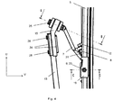
Fig. 1 shows an overall schematic frontal view and an overall schematic lateral view of a twin blade windshield wiper system for a curved windshield of a helicopter, -
Fig. 2 shows a general and two partial detailed side views at enlarged scale of a wiper arm, -
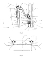
Fig. 3 shows a top view of a part of a twin blade windshield wiper system according to the invention, -
Fig. 4 shows a lateral view of the part of the twin blade windshield wiper system according toFig. 3 , -
Fig. 5 shows two top views of a part of the twin blade windshield wiper system according to the invention with different possible formations of wiper blades on the rocker for achieving an optimal aerodynamic flow on the wiper blades, -
Fig. 6 shows a cross sectional view along the line A-A offigure 3 , -
Fig. 7 , shows a cross sectional view along the line C-C of the part of the twin blade windshield wiper system offigure 4 , -
Fig. 8 shows a schematic cross sectional view of a wiper blade relative to a curved windshield on two different positions of the blade on the windshield with angle definitions, -
Fig. 9 shows two schematic cross sectional views of a part of a twin blade wiper system with the influence of a length (a) on the wiper blade error tolerance lean angle ε, -
Fig. 10 shows a cross sectional view along the line B-B offigure 4 , -
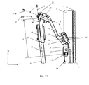
Fig. 11 shows a cross sectional view along the line A-A offigure 3 with an example of a prolongation fitting rotation relative to a curved windshield due to an inclination of a prolongation fitting rotation axes, -
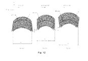
Fig. 12 shows options for different wipe areas of the twin blade windshield wiper system according to the invention. - According to
Figure 1 a pantograph twin bladewindshield wiper system 3 is placed on acurved helicopter windshield 1, with a minimal radius of the windshield curvature of 400 mm in three dimensions. - The twin blade
windshield wiper system 3 has three particular positions within a wiper operation area 4: an end position (C) of thewiper system 3 on the right side of thewindshield 1, a central park position (A) of thewiper system 3 on thewindshield 1 and an end position (B) of thewiper system 3 on the left side of thewindshield 1. Each of said end positions (B) and (C) is angularly separated in opposed directions from the central park position (A) by an angle γ. - An
oscillating gear drive 2 of the twin bladewindshield wiper system 3 is mounted on to thewindshield 1 for driving at least onewiper arm 13 with attachedwiper blades 5. Theoscillating gear drive 2 is arranged to drive the at least onewiper arm 13 with the attachedwiper blades 5 across the wiper operating area 4 angularly separating the right wiper system position (C) from the left wiper system position (B) with an angle 2y. The magnitude value of the angle γ comes from the regulation and is the required magnitude of wiping; here the angle γ is equal to 42°. - The at least one driven
wiper arm 13 of the twin bladewindshield wiper system 3 is mounted on adrive bracket 32. In central park position (A) on thewindshield 1 the longitudinal extension of the at least onedrive bracket 32 defines a longitudinal axis (U) of a coordinate system inherent to thewindshield 1. Said at least onewiper arm 13 is mounted respectively at saidoscillating drive 2 for oscillation about an oscillatory axis (V) across thewindshield 1. Said longitudinal axis (U) is perpendicular to said oscillatory axis (V). A transversal axis (W) of the coordinate system inherent to thewindshield 1 is perpendicular to said oscillatory axis (V) and said longitudinal axis (U). - According to
Fig. 2 corresponding features are referred to with the references ofFig. 1 . A length d of saidwiper arm 13 defines the distance between the center of a wiperarm rotation axis 27 and the center of abore hole 29. Said borehole 29 is located on a crankedfitting 15. The cranked fitting 15 is attached to thewiper arm 13 by a clampingpiece 24 andbolts 28. Said wiperarm rotation axis 27 is perpendicular to the oscillatory axis (V) and allows translation of the cranked fitting 15 along the oscillatory axis (V) to follow the curvature of thewindshield 1. A spring force exerted by aspring 16 biases thewiper blade 5 to thewindshield 1. - The cranked fitting 15 is adjustable on its
wiper arm 13 by means of the clampingpieces 24 andbolts 28 for more adaptive flexibility of thewiper system 3 todifferent windshields 1 for a variable length d of thewiper arm 13. The cranked fitting 15 is rotatable connected with bearingbushes 14 to afit bolt 25. The bearingbushes 14 are integrated in the cranked fitting 15 for rotation about thefit bolt 25. The center line of thefit bolt 25 defines the prolongationfitting rotation axis 17. - According to
Fig. 3 ,4 corresponding features are referred to with references ofFig. 1 and2 . Twowiper blades 5 of thewiper system 3 are pivotally attached to arocker 6 with a distance a between each other. Said twowiper blades 5 are oriented essentially parallel relative to each other on thewindshield 1. Therocker 6 is pivotally attached to aprolongation fitting 7 by means of a rockerfit bolt 12. Theprolongation fitting 7 is pivotally attached to the two crankedfittings 15. Theprolongation fitting 7 is provided with acentral opening 26 to reduce weight. - Each one of said two
wiper blades 5 is pivotally attached to therocker 6 by means of awiper blade shaft 20. Awiper blade holder 19, which holds thewiper blade 5, can rotate about thewiper blade shaft 20. The center line of thewiper blade shaft 20 defines a wiperblade rotation axis 9, where each one of saidwiper blades 5 can rotate independently about the wiperblade rotation axis 9 for maintaining thewiper blades 5 along their longitudinal extension to thewindshield 1. - According to
Fig. 5 corresponding features are referred to with references ofFig. 1 to 4 . Two alternative positions of wiperblade shaft attachments rocker 6 are provided for thewiper system 3. In the 1st alternative of the two positions of thewiper system 3, thewiper blades 5 are arranged without an offset in longitudinal blade direction x relative to each other, i. e. the left and rightwiper blade shafts 20 are positioned to be on a common wiperblade rotation axis 9. In the 2nd alternative position thewiper blades 5 are arranged on two different wiperblade rotation axes wiper blades 5 during operation of thewiper system 3. The aerodynamic flow on the left side and on the right side of thehelicopter windshield 1 is different due to the combination of the flow due to the helicopter forward speed and the flow due to the main rotor. - According to
Fig. 6 and 7 corresponding features are referred to with the references ofFig. 1 to 5 . Therocker 6 is pivotally mounted on the prolongation fitting 7 by means of the bearingbushes 10 and the rockerfit bolt 12 which defines arocker rotation axis 8. The bearingbushes 10, which are integrated in therocker 6, are rotatable about the rockerfit bolt 12 and therocker rotation axis 8. - The plane y' -z' is defined by a perpendicular orientation relative to the longitudinal extension of the
wiper blades 5 and is located in the wiperblade rotation axis 9, here the wiperblade rotation axis 9 has the closest distance to thewindshield surface 1. A plane x'-z' is defined by the perpendicular orientation to the plane y' -z', where the lane wiperblade rotation axis 9 is parallel to the said plane x' -z'. A plane x'-y' is defined by perpendicular orientation to the planes y' -z' and x' -z'. Therocker rotation axis 8 is located in the plane x' -y' in the middle position between thewiper blades 5. Therocker rotation axis 8 is inclined with an angle δ relative to the plane x'-z'. The points P1 and P2 are the contact points between the respectively left and rightwiper blade lips 11 and thewindshield surface 1 in the plane y' -z'. A plane y"-z" is defined by the perpendicular orientation to therocker rotation axis 8 through the points P1 and P2. The point P0 is the intersection point ofrocker rotation axis 8 through the plane y"-z". - The lines L1 and L2 respectively defined by the tangential orientation to the
windshield surface 1 through the contact points P1 and P2 and are located in the plane y"- z". The distances between the lines L1 and L2 and the intersection point P0 are defined as distances bi. For simplification of wiper system design the distance b can be described as the arithmetic average distance
windshield 1 between the twowiper blades 5 across the wiper operating area 4 is small and can be neglect, the distance b can be described as the distance between point P0 and the line connecting the points P1 and P2. - The angle β is to be selected between 0° ≤ /3 < 45° or 135° < β ≤ 180°. The rotation of the
rocker 6 about therocker rotation axis 8 provides the orientation of thewiper blade shaft 20 in the plane y"-z" tangential to thewindshield 1 along thewiper system 3 operating in the transversal direction (W). Therefore the axis of each wiper blade is oriented nearly perpendicular to thewindshield surface 1. - The distance between the
wiper blades 5 is a. The inclination β of therocker rotation axis 8 provides a stable kinematic operating behavior of thewiper system 3, if thestability criterion 
- A soft filler cap is mounted in a
space 31 between therocker 6 and theprolongation fitting 7. The soft filler cap has a stopper function for the rotation of therocker 6 about therocker rotation axis 8 and/or a damping function for an improved dynamic behavior of thewiper system 3. - According to
Fig. 8 corresponding features are referred to with references ofFig. 1 to 7 . The cleaning performance ofwiper blades 5 depends on a lean angle α between a wiper blade axis (s), which is perpendicular to the longitudinal extension of thewiper blade 5 through the contact point of thewiper blade lip 11 with the surface of thewindshield 1, and a perpendicular line yi ' to the windshield surface. The increment i describes the different positions of thewiper blade 5 on thewindshield 1. If thewiper blade 5 is relative to acurved windshield 1 in a central park position (pos. A inFig. 1 ) i = 0 and if thewiper blade 5 is in the left end position (pos. B inFig. 1 ) of thesame wiper blade 5 on the windshield i = 1. It is supposed that the lean angle α of thewiper blade 5 in the central park position i = 0 is equal to zero degree (initial condition). The lean angle α of thewiper blade 5 in all other positions on thewindshield 1 can be defined as α = α T - (α C ± ε). The angle α T is the target lean angle, which describes the necessary rotation angle of the wiper blade axis s perpendicular to the windshield surface. Therefore the angle α T of the wiper blade in the left end position i = 1 is defined to be between the perpendicular line to the windshield in thewiper blade 5 park position y 0' and the perpendicular line to the windshield in thewiper blade 5 left end position y 1'. The angle α C is the wiper system configuration lean angle, which describes the rotation angle of the wiper blade axis s about the wiper blade longitudinal extension given for example by the control parts and/or piloting actuators of wiper system of the prior art. Therefore the angle α C of thewiper blade 5 in the left end position i = 1 is defined to be between the perpendicular line to the windshield in thewiper blade 5 park position y 0' and the wiper blade axis se , which will be expected due to the design of a wiper system. The angle ε is the error tolerance lean angle, which comes for example from the low stiffness of the wiper system components or from other technical/physical aspects. Therefore the angle ε of thewiper blade 5 in the left end position i = 1 is defined to be between the expected wiper blade axis se and the real wiper blade axis s position. - According to
Fig. 9 corresponding features are referred to with references ofFig. 1 to 8 . The inventive twin bladewindshield wiper system 3 allows - across the entire range of oscillation of the wiper blades 5 - the orientation of the wiper blades perpendicular to the windshield without use of additional actuators and/or control arms or other control mechanical parts. The orientation of the inventive twin bladewindshield wiper system 3 is continuously calibrated fully automatically by the windshield itself and the forces exerted on thewiper blades 5 /rocker 6, where thewiper blade shafts 20 will be oriented parallel to the line connecting left and rightwiper blade lips 11 by means of rotation of therocker 6 about therocker rotation axis 8. Therefore thewiper system 3 has an inherent configuration lean angle α C , which is always equal to the target lean angle α T . - With two different distances (a) between two
wiper blades 5 it is visible that reducing length (a) reduces the error tolerance angles ε and therefore reduces the lean angle α with as consequence of a better cleaning performance of thewiper blade 5. Due to the reduced length (a) and the requirement induced by thekinematic stability criterion 
wiper system 3 is stable while ensuring a better cleaning performance of thewiper blade 5. - The target lean angle α T and therefore the configuration lean angle α C , which is to be found in local system y'-z', may not achieve or exceed 90°. Otherwise the
wiper system 3 will be blocked by thewindshield 1 self. Therefore the physical possible range of the configuration lean angle α C due to the twinblade wiper system 3 is defined to be 0° ≤ α C < 90°. - The target lean angle α T along the longitudinal extension of
wiper blade 5 is different to the target lean angle which is required to be in the plane y'-z, due to the possibility of different windshield curvatures along thewiper blade 5 from upper to lower blade edge (twist grade of windshield surface). Therefore the lean angle α along thewiper blades 5 longitudinal extension will be always different by the installation of anywiper system 3 on thecurved windshield 1 within twisted surface degree due to an additional twist grade error tolerance angle ε T . Therefore the twinblade wiper system 3 can be installed on all strongcurved windshields 1 without the significant wiper cleaning performance reduction as far as the twist grade error tolerance angle ε T along the longitudinal extension of thewiper blade 5 does not exceed 20°. - According to
Fig. 10 andFig. 11 corresponding features are referred to with the references ofFig. 1 to 9 . Theprolongation fitting 7 is pivotally mounted on the crankedfittings 15 between the bearingbushes 14 andfit bolts 25. The bearingbushes 14, which are integrated in the crankedfittings 15, can rotate around thefit bolts 25, where the center line of thefit bolts 25 defines the prolongation fitting rotation axes 17. The prolongation fitting rotation axes 17 are parallel to each other and are aligned to provide the pantograph function of thewiper system 3 with at least two drivingly connectedwiper arms 13. - According to a preferred embodiment of the invention the prolongation fitting rotation axes 17 can be inclined in the design plane U-V with respect to a
longitudinal extension axis 18 of the at least onewiper arm 13 at an angle δ. The range of this angle δ can be selected in between 45° < δ < 135°. Due to the oscillation of the at least onewiper arm 13 by thegear drive 2 with an angle γ the prolongation fittingcross beam 23 will rotate about an axis perpendicular to theaxis 18 at the same angle γ. This is the known pantograph function of thewiper system 3 with at least two drivingly connectedwiper arms 13. Due to the inclination of the prolongation fitting rotation axes 17 by the angle δ additional rotation of the prolongation fittingcross beam 23 about the longitudinal extension of the at least onewiper arm 13 will be initiated. The additional rotation of the prolongation fittingcross beam 23 about thelongitudinal extension axis 18 of the at least onewiper arm 13 is given by an angle ϕ, where the angle ϕ is defined by ϕ = γ tan(90° - δ). The total rotation of the prolongation fittingcross beam 23 relative to the longitudinal extension of the at least onewiper arm 13 about the prolongation fitting rotation axes 17 is given by an angle θ defined by
cross beam 23 about thelongitudinal extension axis 18 of the at least onewiper arm 13 and the prolongation fittingcross beam 23 is always parallel to the orientation of thecross beam 23 in park position (A). Due to the selected range 45° < δ < 90° the prolongation fittingcross beam 23 will be oriented in tangential direction to thewindshield 1 within concave curvature by an angle ϕ. Due to the selectedrange 90° < δ < 135° the prolongation fittingcross beam 23 will be oriented in nearly tangential direction relative to thewindshield 1 within convex curvature by an angle ϕ. - According to
Fig. 12 corresponding features are referred to with the references ofFig. 1 to 11 . A width (w) of the wiper operating area 4 depends on the wiper arm length (d) and is defined as the distance between the center of the bore hole on the cranked fitting 29 left and right end positions (B) and (C). Therefore by the selection of the length (d) the width (w) of the wiper operating area 4 can be easily adapted to different windshields with different required wiper operating areas without changes of the gear drive and therefore without changes of the wiper system operating angle γ. - A distance c is defined to be in between a projected point of the center of a
bore hole 29 on the cranked fitting 15 and the projectedwiper blade axis 9 to a plane defined by theaxes 18 of twowiper arms 13. Therefore the design length of prolongation and rocker fitting determines the distance c. Due to the magnitude of this distance c the wiper operating area 4 can be displaced along the axis U away or toward to geardrive 2. - The wiper operating range 4 of the twin
blade wiper system 3 can be adjusted to the different curved andnon-curved windshields 1 with different required wiper areas 4 by the selection of the parameters (a), (c), (d), (β) and (δ) without changes of the oscillating gear drive angle γ. Whereas the distance (a) is responsible for the cleaning performance of thewiper blades 5, the distance (d) is responsible for the width regulation (w) of the wiper operating area 4, the distance (c) is responsible for the displacement of the wiper operating area 4 towards or away fromgear drive 2, the angle β is responsible for the stable kinematic behavior of thewiper system 3 and the combination of the angle β and the angle δ is responsible for the covering of the wiper operating area 4. We show as examples three different forms of the wiper operating area 4: resp. straight (Fig. 12b ), conic 1 (Fig.12a ) and conic 2 (Fig. 12c ). The straight form of the wiper operating area 4 (Fig. 12b ) is obtained if the angle β = 0° or β = 180°. The conic 1 form (Fig. 12a ) of the wiper operating area 4 for theconvex windshield 1 is obtained if the angle β is selected in the range 0° < β < 45° and the angle δ has a magnitude such that ϕ < α T . The conic 2 (Fig. 12c ) form of the wiper operating area 4 for theconvex windshield 1 is obtained if the angle β is selected in the range 180° < β < 135° and the angle δ has a magnitude such as ϕ < α T . The conic 1 form according toFig. 12a or conic 2 form according toFig. 12c of the wiper operating area 4 for the selected inclination angle β is the result at therocker 6 rotation aboutrocker rotation axis 8 relative to theprolongation fitting 7. If the angle δ is selected such that ϕ = α T therocker 6 has no rotation about therocker rotation axis 8 with regard to theprolongation fitting 7 and the form of the wiper operating area 4 is always straight. - An outer surrounding of the wiper operating area 4 exceeds a width (w) towards a section below an ABC reference curve on the
curved windshield 1 for an angle β between 0° < β < 45° and ϕ < α T . By increasing the distance c (shown inFig. 11 ) relative to the center of thebore hole 29 the wiper operating area 4 is displaced towards the gear drive 2 (Fig. 12a ). - An outer surrounding of the wiper operating area 4 for an angle β = 0° or β = 180° provides for corresponding widths (w) along the surface of the
curved windshield 1 with equal sections on both sides of the ABC reference curve. The wiper operating area is not displaced with c = 0 mm (Fig. 12 b ). - An outer surrounding of the wiper operating area 4 exceeds a width (w) towards a section above an ABC reference curve on the
curved windshield 1 for an angle β between 180° < β < 135° and ϕ < α T . By reducing the distance c (described inFig. 11 ) relative to the center of thebore hole 29 the wiper operating area 4 is shifted away from the gear drive 2 (Fig. 12c ). -
- 1
- Windshield
- 2
- Gear Drive
- 3
- Wiper System
- 4
- Wiper Operating Area
- 5
- Wiper Blade(s)
- 6
- Rocker
- 7
- Prolongation Fitting
- 8
- Rocker Rotation Axis
- 9
- Wiper Blade Rotation Axis
- 10
- Bearing Bushes on the Rocker
- 11
- Wiper Blade Lip
- 12
- Fit Bolt (Prolongation Fitting to Rocker)
- 13
- Wiper Arm(s)
- 14
- Bearing Bushes on the Cranked Fitting
- 15
- Cranked Fitting
- 16
- Tension Spring
- 17
- Prolongation Fitting Rotation Axis
- 18
- Wiper Arm Axis (Along the Wiper Arm longitudinal Extension)
- 19
- Wiper Blade Holder
- 20
- Wiper Blade Shaft (or Fit Bolt)
- 21
- Bore Hole on the Rocker for Wiper Blade Attachment
- 22
- Alternative Bore Hole on the Rocker for Wiper Blade Attachment
- 23
- Cross Beam Part of Prolongation Fitting
- 24
- Clamping Pieces
- 25
- Fit Bolt (Prolongation Fitting to Cranked Fitting)
- 26
- Central Opening
- 27
- Wiper Arm Rotation Axis
- 28
- Bolts (Cranked Fitting to Clamping Piece)
- 29
- Centre of the Bore Hole on the Cranked Fitting
- 30
- Centre of the Bore Hole on the Rocker
- 31
- Space for the installation of a soft filler cap
- 32
- Drive Brackets
Claims (9)
- A windshield wiper system (3) for vehicles, particularly a windshield wiper system (3) for helicopters, with a windshield (1) having a curved surface and an oscillating gear drive (2) with a central park position (A), said system (3) comprising:- at least one wiper arm (13) and wiper blades (5), said wiper blades (5) being mounted by means of said at least one wiper arm (13) to said oscillating gear drive (2) for oscillation across the windshield (1) about an oscillatory axis (V),- the windshield (1) and the wiper blade lips (11) have a frictional coefficient (µ),- said wiper blades (5) being mounted to said at least one wiper arm (13) distal to said oscillatory axis (V) and defining in said central park position (A) a longitudinal axis (U) along said curved surface of the windshield (1), and said at least one wiper arm (13) in said central park position (A) being aligned with said longitudinal axis (U); wherein
two wiper arms (13), two wiper blades (5) each with a fit bolt (20), bearing bushes (10), a prolongation fitting (7) and a rocker (6) are provided, said two wiper blades (5) being mounted rotatable about a wiper blade rotation axis (9), perpendicular to said oscillatory axis (V) and said longitudinal axis (U), said wiper blade rotation axis (9), being defined by a center line through the fit bolts (20) mounted opposed to each other on said two wiper blades (5) being essentially parallel with a distance (a) to each other, said rocker (6) rotatable attaching each of the two wiper blades (5) by means of the fit bolt (20), and the prolongation fitting (7) rotatable attaching the rocker (6) to the wiper arms (13), the fit bolt (12) with the rocker (6) defining a rocker rotation axis (8) in a plane defined by said oscillatory axis (V) and said longitudinal axis (U) with an inclination angle β to the outer surface of the windshield (1) in the central park position (A) providing a distance (b) direct under the wiper blades rotation axis (9) between the windshield (1) and the rocker rotation axis (8) perpendicular to the windshield (1) in the central park position (A) fulfilling
- The windshield wiper system (3) according to claim 1, wherein said prolongation fitting (7) is rotatable around a prolongation fitting rotation axis (17) in the plane defined by said oscillatory axis (V) and said longitudinal axis (U) with an inclination angle δ to said wiper arms (13).
- The windshield wiper system (3) according to claim 1, wherein said fit bolt (12) of the rocker rotation axis (8) is 5 to 10 cm away from the windshield (1).
- The windshield wiper system (3) according to claim 1, wherein the ends of said wiper arms (13) are cranked.
- The windshield wiper system (3) according to claim 1, wherein the inclination angle β of said rocker rotation axis (8) is 0° < β < 45° and 135° < β < 180°.
- The windshield wiper system (3) according to claim 1, wherein each one of said two wiper blades (5) can rotate independently around the wiper blade rotation axis (9) relative to the rocker (6).
- The windshield wiper system (3) according to claim 1, wherein the rocker has alternative bore holes (22) to adjust said two wiper blades (5).
- The windshield wiper system (3) according to claim 1, wherein the prolongation fitting (7) is adjustable on said two wiper arms (13), e. g. by means of clamping pieces (24).
- The windshield wiper system (3) according to claim 1, wherein the ends of said wiper arms (14) are cranked with an angle δ between 45° and 135°.
Priority Applications (3)
| Application Number | Priority Date | Filing Date | Title |
|---|---|---|---|
| EP13400026.4A EP2868538B1 (en) | 2013-11-05 | 2013-11-05 | Windshield Wiper System |
| KR1020140144522A KR101744233B1 (en) | 2013-11-05 | 2014-10-23 | Windshield wiper system |
| US14/528,618 US9637089B2 (en) | 2013-11-05 | 2014-10-30 | Windshield wiper system |
Applications Claiming Priority (1)
| Application Number | Priority Date | Filing Date | Title |
|---|---|---|---|
| EP13400026.4A EP2868538B1 (en) | 2013-11-05 | 2013-11-05 | Windshield Wiper System |
Publications (2)
| Publication Number | Publication Date |
|---|---|
| EP2868538A1 true EP2868538A1 (en) | 2015-05-06 |
| EP2868538B1 EP2868538B1 (en) | 2016-06-22 |
Family
ID=49841618
Family Applications (1)
| Application Number | Title | Priority Date | Filing Date |
|---|---|---|---|
| EP13400026.4A Active EP2868538B1 (en) | 2013-11-05 | 2013-11-05 | Windshield Wiper System |
Country Status (3)
| Country | Link |
|---|---|
| US (1) | US9637089B2 (en) |
| EP (1) | EP2868538B1 (en) |
| KR (1) | KR101744233B1 (en) |
Cited By (2)
| Publication number | Priority date | Publication date | Assignee | Title |
|---|---|---|---|---|
| CN112407231A (en) * | 2020-11-27 | 2021-02-26 | 中国商用飞机有限责任公司 | Windscreen wiper device and windscreen cleaning system |
| EP3929040A1 (en) * | 2020-06-25 | 2021-12-29 | Rosemount Aerospace Inc. | Lightning strike protection for an aircraft windshield wiper system |
Families Citing this family (2)
| Publication number | Priority date | Publication date | Assignee | Title |
|---|---|---|---|---|
| RU183496U1 (en) * | 2017-08-30 | 2018-09-24 | Акционерное общество "Камов" | DEVICE FOR CLEANING WINDSHIELD GLASSES IN AIRCRAFT |
| EP3789251A1 (en) * | 2019-09-03 | 2021-03-10 | Arrival Limited | Wiper arrangement |
Citations (8)
| Publication number | Priority date | Publication date | Assignee | Title |
|---|---|---|---|---|
| FR2490565A1 (en) * | 1980-09-19 | 1982-03-26 | Marchal Equip Auto | DEVICE FOR WIPING A SURFACE, PARTICULARLY A MOTOR VEHICLE WINDSHIELD |
| US4553283A (en) * | 1985-02-26 | 1985-11-19 | Speth Peter J | Windshield wiper adapter |
| WO1992005982A1 (en) * | 1990-10-04 | 1992-04-16 | Stefan Battlogg | Windscreen wiper system |
| FR2746355A1 (en) * | 1996-03-22 | 1997-09-26 | Valeo Systemes Dessuyage | Adjustable blade windscreen wiper for motor vehicle |
| US6272717B1 (en) * | 1997-01-27 | 2001-08-14 | Michael Saraydar | Single pivot windshield wiper attachment apparatus |
| WO2005095170A1 (en) * | 2004-04-02 | 2005-10-13 | Valeo Systemes D'essuyage | Wiper arm assembly |
| FR2878802A1 (en) * | 2004-12-08 | 2006-06-09 | Renault Sas | Glass wiper for windshield of motor vehicle, has squeegee that rotates such that wiping blade supports against windshield while preserving angle between average angle and specific degrees with respect to windshield |
| US20070186366A1 (en) * | 2006-02-15 | 2007-08-16 | Alley David J | Windshield wiper and scraper |
Family Cites Families (5)
| Publication number | Priority date | Publication date | Assignee | Title |
|---|---|---|---|---|
| US3874019A (en) | 1973-09-07 | 1975-04-01 | Peter J Speth | Windshield wiper adapter |
| JPH059971Y2 (en) | 1987-06-15 | 1993-03-11 | ||
| DE3824489A1 (en) | 1988-07-20 | 1990-01-25 | Bosch Gmbh Robert | WIPING DEVICE FOR CURVED WINDOWS OF MOTOR VEHICLES |
| FR2757815B1 (en) | 1996-12-31 | 1999-03-26 | Peugeot | DEVICE FOR THE CONTINUOUS ADJUSTMENT OF THE ANGLE OF INCIDENCE OF A SQUEEGEE OF A WINDSCREEN WIPER OF A MOTOR VEHICLE |
| JP4523145B2 (en) | 2000-11-16 | 2010-08-11 | 本田技研工業株式会社 | Wiper device |
-
2013
- 2013-11-05 EP EP13400026.4A patent/EP2868538B1/en active Active
-
2014
- 2014-10-23 KR KR1020140144522A patent/KR101744233B1/en active IP Right Grant
- 2014-10-30 US US14/528,618 patent/US9637089B2/en active Active
Patent Citations (8)
| Publication number | Priority date | Publication date | Assignee | Title |
|---|---|---|---|---|
| FR2490565A1 (en) * | 1980-09-19 | 1982-03-26 | Marchal Equip Auto | DEVICE FOR WIPING A SURFACE, PARTICULARLY A MOTOR VEHICLE WINDSHIELD |
| US4553283A (en) * | 1985-02-26 | 1985-11-19 | Speth Peter J | Windshield wiper adapter |
| WO1992005982A1 (en) * | 1990-10-04 | 1992-04-16 | Stefan Battlogg | Windscreen wiper system |
| FR2746355A1 (en) * | 1996-03-22 | 1997-09-26 | Valeo Systemes Dessuyage | Adjustable blade windscreen wiper for motor vehicle |
| US6272717B1 (en) * | 1997-01-27 | 2001-08-14 | Michael Saraydar | Single pivot windshield wiper attachment apparatus |
| WO2005095170A1 (en) * | 2004-04-02 | 2005-10-13 | Valeo Systemes D'essuyage | Wiper arm assembly |
| FR2878802A1 (en) * | 2004-12-08 | 2006-06-09 | Renault Sas | Glass wiper for windshield of motor vehicle, has squeegee that rotates such that wiping blade supports against windshield while preserving angle between average angle and specific degrees with respect to windshield |
| US20070186366A1 (en) * | 2006-02-15 | 2007-08-16 | Alley David J | Windshield wiper and scraper |
Cited By (4)
| Publication number | Priority date | Publication date | Assignee | Title |
|---|---|---|---|---|
| EP3929040A1 (en) * | 2020-06-25 | 2021-12-29 | Rosemount Aerospace Inc. | Lightning strike protection for an aircraft windshield wiper system |
| US11535358B2 (en) | 2020-06-25 | 2022-12-27 | Rosemount Aerospace Inc. | Lightning strike protection for an aircraft windshield wiper system |
| CN112407231A (en) * | 2020-11-27 | 2021-02-26 | 中国商用飞机有限责任公司 | Windscreen wiper device and windscreen cleaning system |
| CN112407231B (en) * | 2020-11-27 | 2023-04-28 | 中国商用飞机有限责任公司 | Windshield wiper device and windshield cleaning system |
Also Published As
| Publication number | Publication date |
|---|---|
| KR101744233B1 (en) | 2017-06-07 |
| US20150121642A1 (en) | 2015-05-07 |
| EP2868538B1 (en) | 2016-06-22 |
| US9637089B2 (en) | 2017-05-02 |
| KR20150051875A (en) | 2015-05-13 |
Similar Documents
| Publication | Publication Date | Title |
|---|---|---|
| EP2868538A1 (en) | Windshield Wiper System | |
| EP2868537A1 (en) | Windshield Wiper System | |
| US6675433B1 (en) | Beam blade wiper assembly having improved wind lift characteristics | |
| US7802341B2 (en) | Wiper system having a pin-style wiper arm and wiper assembly | |
| US8205291B2 (en) | Wiper system for front windscreens of motor vehicles | |
| EP2025947B1 (en) | Hub-profile connection system for axial fan and axial fan provided with this connection system | |
| CN108025809B (en) | Helicopter with anti-torque system, related kit and method | |
| KR20100134621A (en) | Windscreen wiper device comprising an elastic, elongated carrier element, as well as an elongated wiper blade of a flexible material, which can be placed in abutment with the windscreen to be wiped | |
| CN109153440B (en) | Aircraft with load-reducing wing-like elements | |
| EP2946978B1 (en) | Mechanism for dynamically varying blade load over a windshield wiper sweep cycle | |
| CN111801264B (en) | Steering column for a motor vehicle | |
| EP0280149B1 (en) | Perfected windshield wiper | |
| US20160214574A1 (en) | Fastening device for a windscreen wiping device | |
| US20200130808A1 (en) | Device and method for movably fastening a vehicle system to a primary structure of a vehicle | |
| WO2014158741A1 (en) | Drag reducing mirror assemblies for vehicles | |
| US20160167623A1 (en) | Semi-rigid windshield wiper blade having an offset spoiler | |
| US20080219848A1 (en) | Propeller | |
| US20160297404A1 (en) | Windshield wiper device | |
| FR3026379A1 (en) | PROFILE WING WITH PROGRESSIVE AND SIMULTANEOUS CAMBRIDGE AND INCIDENCE VARIATION | |
| KR20190006555A (en) | Windshield wiper device | |
| EP3501917B1 (en) | Wiper arm device to clean a vehicle windshield and use of the wiper arm device | |
| KR20010101876A (en) | Wiper device for motor vehicle windscreens | |
| EP3647132B1 (en) | Windshield wiper with adaptable attack angle | |
| US20170210344A1 (en) | Windscreen wiper device | |
| EP1844995A2 (en) | Windscreen wiper |
Legal Events
| Date | Code | Title | Description |
|---|---|---|---|
| PUAI | Public reference made under article 153(3) epc to a published international application that has entered the european phase |
Free format text: ORIGINAL CODE: 0009012 |
|
| 17P | Request for examination filed |
Effective date: 20131105 |
|
| AK | Designated contracting states |
Kind code of ref document: A1 Designated state(s): AL AT BE BG CH CY CZ DE DK EE ES FI FR GB GR HR HU IE IS IT LI LT LU LV MC MK MT NL NO PL PT RO RS SE SI SK SM TR |
|
| AX | Request for extension of the european patent |
Extension state: BA ME |
|
| R17P | Request for examination filed (corrected) |
Effective date: 20150520 |
|
| RBV | Designated contracting states (corrected) |
Designated state(s): AL AT BE BG CH CY CZ DE DK EE ES FI FR GB GR HR HU IE IS IT LI LT LU LV MC MK MT NL NO PL PT RO RS SE SI SK SM TR |
|
| GRAP | Despatch of communication of intention to grant a patent |
Free format text: ORIGINAL CODE: EPIDOSNIGR1 |
|
| INTG | Intention to grant announced |
Effective date: 20160301 |
|
| GRAS | Grant fee paid |
Free format text: ORIGINAL CODE: EPIDOSNIGR3 |
|
| GRAA | (expected) grant |
Free format text: ORIGINAL CODE: 0009210 |
|
| AK | Designated contracting states |
Kind code of ref document: B1 Designated state(s): AL AT BE BG CH CY CZ DE DK EE ES FI FR GB GR HR HU IE IS IT LI LT LU LV MC MK MT NL NO PL PT RO RS SE SI SK SM TR |
|
| REG | Reference to a national code |
Ref country code: GB Ref legal event code: FG4D |
|
| REG | Reference to a national code |
Ref country code: CH Ref legal event code: NV Representative=s name: E. BLUM AND CO. AG PATENT- UND MARKENANWAELTE , CH Ref country code: CH Ref legal event code: EP |
|
| REG | Reference to a national code |
Ref country code: IE Ref legal event code: FG4D |
|
| REG | Reference to a national code |
Ref country code: AT Ref legal event code: REF Ref document number: 807468 Country of ref document: AT Kind code of ref document: T Effective date: 20160715 |
|
| REG | Reference to a national code |
Ref country code: DE Ref legal event code: R096 Ref document number: 602013008738 Country of ref document: DE |
|
| REG | Reference to a national code |
Ref country code: LT Ref legal event code: MG4D |
|
| REG | Reference to a national code |
Ref country code: NL Ref legal event code: MP Effective date: 20160622 |
|
| PG25 | Lapsed in a contracting state [announced via postgrant information from national office to epo] |
Ref country code: NO Free format text: LAPSE BECAUSE OF FAILURE TO SUBMIT A TRANSLATION OF THE DESCRIPTION OR TO PAY THE FEE WITHIN THE PRESCRIBED TIME-LIMIT Effective date: 20160922 Ref country code: FI Free format text: LAPSE BECAUSE OF FAILURE TO SUBMIT A TRANSLATION OF THE DESCRIPTION OR TO PAY THE FEE WITHIN THE PRESCRIBED TIME-LIMIT Effective date: 20160622 Ref country code: LT Free format text: LAPSE BECAUSE OF FAILURE TO SUBMIT A TRANSLATION OF THE DESCRIPTION OR TO PAY THE FEE WITHIN THE PRESCRIBED TIME-LIMIT Effective date: 20160622 |
|
| REG | Reference to a national code |
Ref country code: AT Ref legal event code: MK05 Ref document number: 807468 Country of ref document: AT Kind code of ref document: T Effective date: 20160622 |
|
| REG | Reference to a national code |
Ref country code: FR Ref legal event code: PLFP Year of fee payment: 4 |
|
| PG25 | Lapsed in a contracting state [announced via postgrant information from national office to epo] |
Ref country code: LV Free format text: LAPSE BECAUSE OF FAILURE TO SUBMIT A TRANSLATION OF THE DESCRIPTION OR TO PAY THE FEE WITHIN THE PRESCRIBED TIME-LIMIT Effective date: 20160622 Ref country code: HR Free format text: LAPSE BECAUSE OF FAILURE TO SUBMIT A TRANSLATION OF THE DESCRIPTION OR TO PAY THE FEE WITHIN THE PRESCRIBED TIME-LIMIT Effective date: 20160622 Ref country code: RS Free format text: LAPSE BECAUSE OF FAILURE TO SUBMIT A TRANSLATION OF THE DESCRIPTION OR TO PAY THE FEE WITHIN THE PRESCRIBED TIME-LIMIT Effective date: 20160622 Ref country code: SE Free format text: LAPSE BECAUSE OF FAILURE TO SUBMIT A TRANSLATION OF THE DESCRIPTION OR TO PAY THE FEE WITHIN THE PRESCRIBED TIME-LIMIT Effective date: 20160622 Ref country code: GR Free format text: LAPSE BECAUSE OF FAILURE TO SUBMIT A TRANSLATION OF THE DESCRIPTION OR TO PAY THE FEE WITHIN THE PRESCRIBED TIME-LIMIT Effective date: 20160923 Ref country code: NL Free format text: LAPSE BECAUSE OF FAILURE TO SUBMIT A TRANSLATION OF THE DESCRIPTION OR TO PAY THE FEE WITHIN THE PRESCRIBED TIME-LIMIT Effective date: 20160622 |
|
| PG25 | Lapsed in a contracting state [announced via postgrant information from national office to epo] |
Ref country code: CZ Free format text: LAPSE BECAUSE OF FAILURE TO SUBMIT A TRANSLATION OF THE DESCRIPTION OR TO PAY THE FEE WITHIN THE PRESCRIBED TIME-LIMIT Effective date: 20160622 Ref country code: RO Free format text: LAPSE BECAUSE OF FAILURE TO SUBMIT A TRANSLATION OF THE DESCRIPTION OR TO PAY THE FEE WITHIN THE PRESCRIBED TIME-LIMIT Effective date: 20160622 Ref country code: IS Free format text: LAPSE BECAUSE OF FAILURE TO SUBMIT A TRANSLATION OF THE DESCRIPTION OR TO PAY THE FEE WITHIN THE PRESCRIBED TIME-LIMIT Effective date: 20161022 Ref country code: SK Free format text: LAPSE BECAUSE OF FAILURE TO SUBMIT A TRANSLATION OF THE DESCRIPTION OR TO PAY THE FEE WITHIN THE PRESCRIBED TIME-LIMIT Effective date: 20160622 Ref country code: EE Free format text: LAPSE BECAUSE OF FAILURE TO SUBMIT A TRANSLATION OF THE DESCRIPTION OR TO PAY THE FEE WITHIN THE PRESCRIBED TIME-LIMIT Effective date: 20160622 |
|
| PG25 | Lapsed in a contracting state [announced via postgrant information from national office to epo] |
Ref country code: PL Free format text: LAPSE BECAUSE OF FAILURE TO SUBMIT A TRANSLATION OF THE DESCRIPTION OR TO PAY THE FEE WITHIN THE PRESCRIBED TIME-LIMIT Effective date: 20160622 Ref country code: ES Free format text: LAPSE BECAUSE OF FAILURE TO SUBMIT A TRANSLATION OF THE DESCRIPTION OR TO PAY THE FEE WITHIN THE PRESCRIBED TIME-LIMIT Effective date: 20160622 Ref country code: SM Free format text: LAPSE BECAUSE OF FAILURE TO SUBMIT A TRANSLATION OF THE DESCRIPTION OR TO PAY THE FEE WITHIN THE PRESCRIBED TIME-LIMIT Effective date: 20160622 Ref country code: AT Free format text: LAPSE BECAUSE OF FAILURE TO SUBMIT A TRANSLATION OF THE DESCRIPTION OR TO PAY THE FEE WITHIN THE PRESCRIBED TIME-LIMIT Effective date: 20160622 Ref country code: BE Free format text: LAPSE BECAUSE OF FAILURE TO SUBMIT A TRANSLATION OF THE DESCRIPTION OR TO PAY THE FEE WITHIN THE PRESCRIBED TIME-LIMIT Effective date: 20160622 Ref country code: PT Free format text: LAPSE BECAUSE OF FAILURE TO SUBMIT A TRANSLATION OF THE DESCRIPTION OR TO PAY THE FEE WITHIN THE PRESCRIBED TIME-LIMIT Effective date: 20161024 |
|
| REG | Reference to a national code |
Ref country code: DE Ref legal event code: R097 Ref document number: 602013008738 Country of ref document: DE |
|
| PLBE | No opposition filed within time limit |
Free format text: ORIGINAL CODE: 0009261 |
|
| STAA | Information on the status of an ep patent application or granted ep patent |
Free format text: STATUS: NO OPPOSITION FILED WITHIN TIME LIMIT |
|
| 26N | No opposition filed |
Effective date: 20170323 |
|
| PG25 | Lapsed in a contracting state [announced via postgrant information from national office to epo] |
Ref country code: DK Free format text: LAPSE BECAUSE OF FAILURE TO SUBMIT A TRANSLATION OF THE DESCRIPTION OR TO PAY THE FEE WITHIN THE PRESCRIBED TIME-LIMIT Effective date: 20160622 |
|
| REG | Reference to a national code |
Ref country code: IE Ref legal event code: MM4A |
|
| PG25 | Lapsed in a contracting state [announced via postgrant information from national office to epo] |
Ref country code: SI Free format text: LAPSE BECAUSE OF FAILURE TO SUBMIT A TRANSLATION OF THE DESCRIPTION OR TO PAY THE FEE WITHIN THE PRESCRIBED TIME-LIMIT Effective date: 20160622 |
|
| PG25 | Lapsed in a contracting state [announced via postgrant information from national office to epo] |
Ref country code: LU Free format text: LAPSE BECAUSE OF NON-PAYMENT OF DUE FEES Effective date: 20161130 |
|
| REG | Reference to a national code |
Ref country code: FR Ref legal event code: PLFP Year of fee payment: 5 |
|
| PG25 | Lapsed in a contracting state [announced via postgrant information from national office to epo] |
Ref country code: IE Free format text: LAPSE BECAUSE OF NON-PAYMENT OF DUE FEES Effective date: 20161105 |
|
| PG25 | Lapsed in a contracting state [announced via postgrant information from national office to epo] |
Ref country code: HU Free format text: LAPSE BECAUSE OF FAILURE TO SUBMIT A TRANSLATION OF THE DESCRIPTION OR TO PAY THE FEE WITHIN THE PRESCRIBED TIME-LIMIT; INVALID AB INITIO Effective date: 20131105 |
|
| PG25 | Lapsed in a contracting state [announced via postgrant information from national office to epo] |
Ref country code: MC Free format text: LAPSE BECAUSE OF FAILURE TO SUBMIT A TRANSLATION OF THE DESCRIPTION OR TO PAY THE FEE WITHIN THE PRESCRIBED TIME-LIMIT Effective date: 20160622 Ref country code: CY Free format text: LAPSE BECAUSE OF FAILURE TO SUBMIT A TRANSLATION OF THE DESCRIPTION OR TO PAY THE FEE WITHIN THE PRESCRIBED TIME-LIMIT Effective date: 20160622 Ref country code: MK Free format text: LAPSE BECAUSE OF FAILURE TO SUBMIT A TRANSLATION OF THE DESCRIPTION OR TO PAY THE FEE WITHIN THE PRESCRIBED TIME-LIMIT Effective date: 20160622 |
|
| PG25 | Lapsed in a contracting state [announced via postgrant information from national office to epo] |
Ref country code: BG Free format text: LAPSE BECAUSE OF FAILURE TO SUBMIT A TRANSLATION OF THE DESCRIPTION OR TO PAY THE FEE WITHIN THE PRESCRIBED TIME-LIMIT Effective date: 20160622 |
|
| PG25 | Lapsed in a contracting state [announced via postgrant information from national office to epo] |
Ref country code: MT Free format text: LAPSE BECAUSE OF NON-PAYMENT OF DUE FEES Effective date: 20161105 |
|
| PG25 | Lapsed in a contracting state [announced via postgrant information from national office to epo] |
Ref country code: AL Free format text: LAPSE BECAUSE OF FAILURE TO SUBMIT A TRANSLATION OF THE DESCRIPTION OR TO PAY THE FEE WITHIN THE PRESCRIBED TIME-LIMIT Effective date: 20160622 Ref country code: TR Free format text: LAPSE BECAUSE OF FAILURE TO SUBMIT A TRANSLATION OF THE DESCRIPTION OR TO PAY THE FEE WITHIN THE PRESCRIBED TIME-LIMIT Effective date: 20160622 |
|
| PGFP | Annual fee paid to national office [announced via postgrant information from national office to epo] |
Ref country code: IT Payment date: 20221124 Year of fee payment: 10 Ref country code: GB Payment date: 20221122 Year of fee payment: 10 Ref country code: FR Payment date: 20221129 Year of fee payment: 10 Ref country code: DE Payment date: 20221123 Year of fee payment: 10 |
|
| PGFP | Annual fee paid to national office [announced via postgrant information from national office to epo] |
Ref country code: CH Payment date: 20221114 Year of fee payment: 10 |
|
| P01 | Opt-out of the competence of the unified patent court (upc) registered |
Effective date: 20230530 |