EP2867713B1 - Infrared imaging system - Google Patents
Infrared imaging system Download PDFInfo
- Publication number
- EP2867713B1 EP2867713B1 EP13795314.7A EP13795314A EP2867713B1 EP 2867713 B1 EP2867713 B1 EP 2867713B1 EP 13795314 A EP13795314 A EP 13795314A EP 2867713 B1 EP2867713 B1 EP 2867713B1
- Authority
- EP
- European Patent Office
- Prior art keywords
- view
- field
- infrared imaging
- infrared
- imaging sensor
- Prior art date
- Legal status (The legal status is an assumption and is not a legal conclusion. Google has not performed a legal analysis and makes no representation as to the accuracy of the status listed.)
- Active
Links
- 238000003331 infrared imaging Methods 0.000 title claims description 20
- 230000003287 optical effect Effects 0.000 claims description 80
- 230000005670 electromagnetic radiation Effects 0.000 claims description 17
- 230000007246 mechanism Effects 0.000 claims description 13
- 230000033001 locomotion Effects 0.000 claims description 10
- 238000003384 imaging method Methods 0.000 claims description 6
- 230000003595 spectral effect Effects 0.000 claims description 6
- 238000000034 method Methods 0.000 claims description 4
- 230000009977 dual effect Effects 0.000 claims description 2
- 230000008569 process Effects 0.000 claims description 2
- 210000004027 cell Anatomy 0.000 description 51
- 230000000712 assembly Effects 0.000 description 15
- 238000000429 assembly Methods 0.000 description 15
- 238000010586 diagram Methods 0.000 description 7
- 238000005516 engineering process Methods 0.000 description 4
- 230000005855 radiation Effects 0.000 description 4
- 238000012937 correction Methods 0.000 description 3
- 238000013461 design Methods 0.000 description 3
- 239000000463 material Substances 0.000 description 3
- 230000006641 stabilisation Effects 0.000 description 3
- 238000011105 stabilization Methods 0.000 description 3
- 238000012546 transfer Methods 0.000 description 3
- PFNQVRZLDWYSCW-UHFFFAOYSA-N (fluoren-9-ylideneamino) n-naphthalen-1-ylcarbamate Chemical compound C12=CC=CC=C2C2=CC=CC=C2C1=NOC(=O)NC1=CC=CC2=CC=CC=C12 PFNQVRZLDWYSCW-UHFFFAOYSA-N 0.000 description 2
- 239000005083 Zinc sulfide Substances 0.000 description 2
- 230000004075 alteration Effects 0.000 description 2
- OYLGJCQECKOTOL-UHFFFAOYSA-L barium fluoride Chemical compound [F-].[F-].[Ba+2] OYLGJCQECKOTOL-UHFFFAOYSA-L 0.000 description 2
- 229910001632 barium fluoride Inorganic materials 0.000 description 2
- 230000005540 biological transmission Effects 0.000 description 2
- 229910052732 germanium Inorganic materials 0.000 description 2
- GNPVGFCGXDBREM-UHFFFAOYSA-N germanium atom Chemical compound [Ge] GNPVGFCGXDBREM-UHFFFAOYSA-N 0.000 description 2
- 230000006872 improvement Effects 0.000 description 2
- 230000010354 integration Effects 0.000 description 2
- 238000005259 measurement Methods 0.000 description 2
- 238000012986 modification Methods 0.000 description 2
- 230000004048 modification Effects 0.000 description 2
- 229910052984 zinc sulfide Inorganic materials 0.000 description 2
- JBRZTFJDHDCESZ-UHFFFAOYSA-N AsGa Chemical compound [As]#[Ga] JBRZTFJDHDCESZ-UHFFFAOYSA-N 0.000 description 1
- BUGBHKTXTAQXES-UHFFFAOYSA-N Selenium Chemical compound [Se] BUGBHKTXTAQXES-UHFFFAOYSA-N 0.000 description 1
- 238000013459 approach Methods 0.000 description 1
- 150000001495 arsenic compounds Chemical class 0.000 description 1
- 230000000903 blocking effect Effects 0.000 description 1
- 150000004770 chalcogenides Chemical class 0.000 description 1
- 230000008859 change Effects 0.000 description 1
- 238000004891 communication Methods 0.000 description 1
- 238000010276 construction Methods 0.000 description 1
- 238000001816 cooling Methods 0.000 description 1
- 238000001514 detection method Methods 0.000 description 1
- 239000000428 dust Substances 0.000 description 1
- 230000000694 effects Effects 0.000 description 1
- 239000003897 fog Substances 0.000 description 1
- 229940093920 gynecological arsenic compound Drugs 0.000 description 1
- 238000009434 installation Methods 0.000 description 1
- 210000003644 lens cell Anatomy 0.000 description 1
- 238000012423 maintenance Methods 0.000 description 1
- 230000014759 maintenance of location Effects 0.000 description 1
- 238000004519 manufacturing process Methods 0.000 description 1
- 230000000116 mitigating effect Effects 0.000 description 1
- 238000012545 processing Methods 0.000 description 1
- 239000011669 selenium Substances 0.000 description 1
- 229910052711 selenium Inorganic materials 0.000 description 1
- 230000035945 sensitivity Effects 0.000 description 1
- 239000000779 smoke Substances 0.000 description 1
- 238000001931 thermography Methods 0.000 description 1
- DRDVZXDWVBGGMH-UHFFFAOYSA-N zinc;sulfide Chemical compound [S-2].[Zn+2] DRDVZXDWVBGGMH-UHFFFAOYSA-N 0.000 description 1
Images


Classifications
-
- H—ELECTRICITY
- H04—ELECTRIC COMMUNICATION TECHNIQUE
- H04N—PICTORIAL COMMUNICATION, e.g. TELEVISION
- H04N5/00—Details of television systems
- H04N5/30—Transforming light or analogous information into electric information
- H04N5/33—Transforming infrared radiation
-
- G—PHYSICS
- G01—MEASURING; TESTING
- G01S—RADIO DIRECTION-FINDING; RADIO NAVIGATION; DETERMINING DISTANCE OR VELOCITY BY USE OF RADIO WAVES; LOCATING OR PRESENCE-DETECTING BY USE OF THE REFLECTION OR RERADIATION OF RADIO WAVES; ANALOGOUS ARRANGEMENTS USING OTHER WAVES
- G01S17/00—Systems using the reflection or reradiation of electromagnetic waves other than radio waves, e.g. lidar systems
- G01S17/02—Systems using the reflection of electromagnetic waves other than radio waves
- G01S17/04—Systems determining the presence of a target
-
- G—PHYSICS
- G01—MEASURING; TESTING
- G01S—RADIO DIRECTION-FINDING; RADIO NAVIGATION; DETERMINING DISTANCE OR VELOCITY BY USE OF RADIO WAVES; LOCATING OR PRESENCE-DETECTING BY USE OF THE REFLECTION OR RERADIATION OF RADIO WAVES; ANALOGOUS ARRANGEMENTS USING OTHER WAVES
- G01S7/00—Details of systems according to groups G01S13/00, G01S15/00, G01S17/00
- G01S7/48—Details of systems according to groups G01S13/00, G01S15/00, G01S17/00 of systems according to group G01S17/00
- G01S7/481—Constructional features, e.g. arrangements of optical elements
-
- G—PHYSICS
- G02—OPTICS
- G02B—OPTICAL ELEMENTS, SYSTEMS OR APPARATUS
- G02B13/00—Optical objectives specially designed for the purposes specified below
- G02B13/14—Optical objectives specially designed for the purposes specified below for use with infrared or ultraviolet radiation
- G02B13/146—Optical objectives specially designed for the purposes specified below for use with infrared or ultraviolet radiation with corrections for use in multiple wavelength bands, such as infrared and visible light, e.g. FLIR systems
-
- G—PHYSICS
- G02—OPTICS
- G02B—OPTICAL ELEMENTS, SYSTEMS OR APPARATUS
- G02B23/00—Telescopes, e.g. binoculars; Periscopes; Instruments for viewing the inside of hollow bodies; Viewfinders; Optical aiming or sighting devices
- G02B23/12—Telescopes, e.g. binoculars; Periscopes; Instruments for viewing the inside of hollow bodies; Viewfinders; Optical aiming or sighting devices with means for image conversion or intensification
-
- G—PHYSICS
- G01—MEASURING; TESTING
- G01S—RADIO DIRECTION-FINDING; RADIO NAVIGATION; DETERMINING DISTANCE OR VELOCITY BY USE OF RADIO WAVES; LOCATING OR PRESENCE-DETECTING BY USE OF THE REFLECTION OR RERADIATION OF RADIO WAVES; ANALOGOUS ARRANGEMENTS USING OTHER WAVES
- G01S7/00—Details of systems according to groups G01S13/00, G01S15/00, G01S17/00
- G01S7/48—Details of systems according to groups G01S13/00, G01S15/00, G01S17/00 of systems according to group G01S17/00
- G01S7/497—Means for monitoring or calibrating
Definitions
- FLIR imaging systems are used in many applications by many organizations, including the U.S. Army.
- a common module approach has been adopted for the production and fielding of FLIR systems to allow common access to core FLIR components in order to reduce costs and facilitate maintenance, while maintaining flexibility in the sensor configuration and a common look and feel between sensors.
- the Army uses FLIR kits (that include one or more FLIR modules) in the majority of ground combat vehicle platform sensors.
- FLIR kits that include one or more FLIR modules
- weapon sights that are based on FLIR technology support battlefield surveillance and target acquisition. They allow gunners and field commanders to detect, identify and target enemy platforms even for conditions of low visibility, for example, at night and/or when there are obscurants such as smoke, fog and dust in the air.
- Some conventional FLIR kits do not provide the ability to detect, recognize or identify threats at very long range, for example, at ranges that exceed the threat engagement range or maximum munitions range.
- the sensor field of view may be narrower than may be desired to support short acquisition times.
- Attempts to upgrade FLIR modules for improved performance with advances in technology have included replacing the entire sensor system (which is expensive), and upgrading with small pixel longwave infrared (LWIR) sensors which, although providing better performance than the sensors used in some older systems, still do not provide the highest levels of performance, due to limitations of a single spectral band in a space constrained installation.
- LWIR small pixel longwave infrared
- Certain embodiments are directed to an infrared imaging sensor that supports upgrades to 2 nd Generation Forward Looking Infrared (FLIR) Horizontal Technology Integration (HTI) B-Kit based sensors by fitting with space available within applicable A-Kits and providing significantly improved detection, recognition, and identification range.
- FLIR Forward Looking Infrared
- HTI Horizontal Technology Integration
- aspects and embodiments are directed to a FLIR B-kit that includes a set of refractive opto-mechanical modules and backward-compatible electronics modules which may be used to upgrade existing Second Generation FLIR HTI B-kit based sensor systems to provide greatly extended identification range and/or an ultrawide field of view (FOV). Electronics modules can also be used to sustain Second Generation FLIR HTI sensors.
- Embodiments of the FLIR B-kits are configured to fit within the footprint of existing Second Generation FLIR HTI B-kit modules, thereby providing an effective retrofit option for sensor systems.
- the present invention provides infrared imaging sensors as recited in the claims.
- the afocal optical module is configured to provide at least four fields of view.
- the at least four fields of view include an ultranarrow field of view, a narrow field of view, a wide field of view, and an ultrawide field of view.
- the at least four fields of view includes five fields of view, further including a medium field of view.
- the receiver assembly may include a FOV mechanism configured to switch the field of view of the sensor between the ultranarrow field of view and the narrow field of view.
- the at least four fields of view include an ultranarrow field of view, a narrow field of view, a medium field of view, and a wide field of view.
- the focus cell is an eyepiece for the afocal optical module.
- an infrared imaging sensor comprises an afocal optical assembly including an input aperture configured to receive infrared electromagnetic radiation from a distant object, a focus cell, a plurality of field of view (FOV) cells disposed on a rotating structure configured to rotate with respect to the focus cell so as to align one of the plurality of FOV cells with the focus cell, wherein each of the FOV cells has a different field of view, a receiver assembly including a detector optically coupled to the focus cell and configured to receive the infrared electromagnetic radiation from the focus cell and to provide an image of the distant object, and at least one electronics module configured to interface the infrared imaging sensor with other sensor modules and to process the image of the distant object.
- afocal optical assembly including an input aperture configured to receive infrared electromagnetic radiation from a distant object, a focus cell, a plurality of field of view (FOV) cells disposed on a rotating structure configured to rotate with respect to the focus cell so as to align one of the plurality of FOV cells with the focus cell, where
- the plurality of FOV cells includes an ultranarrow FOV cell, a wide FOV cell, and an ultrawide FOV cell.
- the afocal optical assembly may further include a movable lens configured to be movable into and out of an optical path between the input aperture and at least one of the FOV cells.
- the plurality of FOV cells includes a medium FOV cell, a wide FOV cell, and optionally an ultrawide FOV cell, and the receiver assembly further includes a FOV mechanism configured to switch the field of view of the sensor between an ultranarrow field of view and a narrow field of view.
- the infrared electromagnetic radiation includes mid-wave infrared radiation in a wavelength range of approximately 3 to 5 micrometers and long-wave infrared radiation in a wavelength range of approximately 8 to 12 micrometers.
- the FLIR B-kit includes a set of infrared (IR) sensor modules, including one or more refractive opto-mechanical modules and electronics modules.
- the electronics modules may include electronic circuit card assemblies that are backward compatible with legacy Second Generation FLIR B-kits and forward compatible with Third Generation FLIR B-kits.
- Backward compatibility provides obsolescence mitigation to Second Generation FLIR HTI modules, and forward compatibility allows Third Generation FLIR B-kits to reuse the electronics modules while upgrading Second Generation FLIR B-kits with new features.
- Embodiments of the FLIR B-kit in addition to matching field of view of the existing Second Generation FLIR HTI B-Kit, provide a field of view that provides improved sensor resolution, allowing sensor systems to achieve far greater range performance (in some examples, under good conditions, more than doubling the acquisition range compared to legacy Second Generation FLIR B-kit based sensor systems), and may provide a wider field of view, as discussed further below.
- the sight assembly 100 includes a sight chassis 110 that houses circuit card assemblies 122, 124 and optionally 126, a receiver assembly 130, and an afocal optical assembly 140.
- the receiver assembly 130 and afocal optical assembly 140 are mounted within the chassis 110 and coupled to other components via flexible circuit assemblies 152, 154, respectively.
- the sight assembly 100 may further include an electromagnetic interference shield assembly 160.
- the circuit card assembly 122 is a mechanism control circuit card assembly
- the circuit card assemblies 124, 126 are digital processing circuit cards, as discussed further below.
- FIG. 1B illustrates an example of an assembled system 170 including element 100 (shown assembled), to include the components shown in FIG. 1A .
- the sight 170 further includes a slip ring assembly 180 and a head mirror assembly 190.
- elements 122, 124, 126, 130, and 140 make up a B-Kit which may be common between multiple sensor systems; and elements 160, 154, 110, and 152 are components which may be included in an "A-Kit" that may be unique to different sensor systems.
- the B-Kit common components are configured to fit within the space allocated in existing systems for conventional Second Generation FLIR B-Kit modules, such that they may be used as retrofit components.
- the overall dimensions of the assembled sight 170 may be comparable to those of sight assemblies incorporating Second Generation FLIR B-kits, such that these sight assemblies may be easily accommodated as a replacement part within existing systems.
- FIG. 5A is a block diagram of one example of an optical system showing an example of the relationship between a B-Kit 500 and an A-Kit 510.
- the A-kit may include various structure and components used to install and operate the optical system, including, for example, gimbals (for mounting the system to a vehicle or other platform), line-of-sight controls and gyroscopes, interconnects to other systems, and user interfaces (such as controls and displays).
- jitter such as may occur due to movement of the sight as it is used
- the head mirror assembly 190 or A-kit 510 includes a gyroscope configured to help improve image stabilization as discussed further below.
- the afocal optical assembly 140 includes an objective lens 520 that receives incident electromagnetic radiation 530 and directs it into the afocal optical assembly.
- the afocal optical assembly has a plurality of selectable fields of view implemented using a plurality of field-of-view (FOV) cells mounted on a rotary turret 310 that allows a user to select between fields of view, as discussed further below.
- the electromagnetic radiation is directed via a selected one of the FOV cells to a focus cell 220, which directs the electromagnetic radiation to the receiver assembly 130.
- Embodiments of the afocal optical assembly 140 are discussed in more detail below with reference to FIGS. 3A - 3F .
- the receiver assembly 130 includes an optical imager 540 which may include a plurality of lenses and/or mirrors configured to receive and focus the incoming electromagnetic radiation 530 from the focus cell 220 onto a detector 550.
- the detector may be a focal plane array, or other imaging detector.
- the detector 550 is housed within a Dewar 230 which may be cooled by a cryogenic cooler 410.
- the receiver assembly 130 is discussed further below with reference to FIGS. 4A and 4B .
- FIG. 2 illustrates an example of an assembled FLIR B-kit according to one embodiment, including the afocal optical assembly 140 and receiver assembly 130 assembled within the sight chassis 110.
- the B-kit 500 includes one or more circuit card assemblies 122, 124, and/or 126.
- circuit card assemblies 124 and/or 126 provide control and status communication, as well as video data transfer between the components of the B-kit 500 and the A-kit 510.
- the B-kit may further include a power filter and conditioner 560 that receives power from the A-kit 510 and supplies power to components of B-kit 500, as necessary, optionally via flexible circuit assemblies 153 and 154, to the circuit card assembly 122 and/or circuit card assemblies 124 and/or 126.
- the receiver assembly 130 includes an image motion compensation (IMC) mirror 210 that directs light from the focus cell 220 of the afocal optical assembly 140 through the optical imager 540 to the detector 550 located within the Dewar 230.
- the IMC mirror 210 may be used to reduce jitter and improve image stabilization.
- at least one of the circuit card assemblies 122, 124, and/or 126 included in the FLIR B-kit 500 includes an image motion compensation controller that is configured to compensate for error in the movement of the head mirror measured using a gyroscope, as discussed above.
- the head mirror in the head mirror assembly 190 may be relatively large and/or heavy, and accordingly, may be limited in fine motion.
- the image motion compensation controller may adjust positioning of the IMC mirror 210 based on measurements from the gyroscope to compensate for jitter and improve image stabilization and reduce blur.
- the IMC mirror 210 may be used to provide "backscan” which temporarily counteracts line-of-sight motion to "freeze” an image during image collection before stepping to the next image location, thereby allowing rapid wide area searching.
- the afocal optical assembly is configured with multiple different selectable fields of view.
- the afocal optical assembly 140 includes multiple FOV cells arranged on the rotatable turret 310. By rotating the turret 310, any one of the FOV cells may be aligned with the focus cell 220 thereby achieving a selected field of view for the sight.
- the rotatable turret 310 is referred to as a rotating FOV wheel.
- the afocal optical assembly has four selectable fields of view, namely an ultranarrow field of view (UNFOV), a narrow field of view (NFOV), a wide field of view (WFOV), and an ultrawide field of view (UWFOV).
- UWFOV ultranarrow field of view
- Other embodiments replace the UWFOV with a medium field of view (MFOV), or implement optics that support five fields of view (for example, UNFOV, NFOV, MFOV, WFOV, and UWFOV), as discussed further below.
- the afocal optical assembly 140 includes a WFOV cell 330, a UWFOV cell 320, and a UNFOV cell 340.
- the optical system has a field of view of approximately 1.24 degrees horizontal by 0.7 degrees vertical in the UNFOV configuration (i.e., with the UNFOV cell 340 aligned with the focus cell 220).
- the optical system has a field of view of approximately 13.3 degrees horizontal by 7.5 degrees vertical in the WFOV configuration.
- the optical system has a field of view of approximately 21.9 degrees horizontal by 12.3 degrees vertical in the UWFOV configuration.
- the optical system may have a field of view of approximately 3.56 degrees horizontal by 2.0 degrees vertical in the NFOV configuration, and a field of view of approximately 7.1 degrees horizontal by 4 degrees vertical in the MFOV configuration.
- the optical parameters and design of the afocal optical assembly 140 uses the NFOV configuration as the basis for the optical design.
- the FOV wheel has an opening and does not include any lenses, so that the objective lenses 520, focus lens cell, and "downstream" optical components define the NFOV.
- a flip lens 350 may be used for the UNFOV configuration. As illustrated in FIGS. 3A and 3B , in one embodiment, the flip lens 350 may be configured to be movable into and out of the optical path over the UNFOV cell 340. FIGS. 3A and 3B show the lens 350 flipped into the optical path.
- the rotating FOV wheel 310 is positioned such that the UNFOV cell 340 is aligned over the focus cell 220 or "eyepiece" of the afocal optical assembly 140.
- An actuator assembly 355 may be used to effect the movement of the flip lens 350.
- the UNFOV cell and the flip lens 350 are positioned in the NFOV optical path, aligned with the focus cell 220.
- FIGS. 3D-3F illustrate configurations of the afocal optical assembly 140 for different fields of view.
- FIG. 3D illustrates an example of the NFOV configuration, in which the flip lens 350 is positioned out of the optical path, and an "empty" slot on the structure 310 is positioned over the focus cell 220 since, as discussed above, in this example the NFOV configuration forms the basis for the optical design.
- FIG. 3E illustrates an example of the WFOV configuration in which the flip lens 350 is positioned out of the optical path, and the structure 310 is rotated such that the WFOV cell 330 is positioned in the optical path aligned with the focus cell 220.
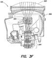
- FIG. 3F illustrates an example of the UWFOV configuration in which the flip lens 350 is positioned out of the optical path, and the structure 310 is rotated such that the UWFOV cell 320 is positioned in the optical path aligned with the focus cell 220.
- the afocal optical assembly 140 is a fully refractive optical system (optionally excluding planar fold mirrors as discussed further below) to provide a compact optical assembly which may be accommodated within the space allocated to legacy optical assemblies in existing systems.
- the afocal assembly utilizes a combination of reflective and refractive lenses which, while may not be easily packaged into some A-Kits, may be more optimal for others.
- the afocal optical assembly 140 may also include a thermal reference source 360 positioned on the rotating FOV wheel 310.
- the thermal reference source 360 may be configured to produce infrared radiation having known characteristics (e.g., predetermined spectral characteristics and intensity).
- the thermal reference source 360 may be rotated into alignment with the focus cell 220 such that the known radiation is supplied to the detector in the receiver assembly 130. Measurements from the detector of the thermal reference source 360 may be used to calibrate the sensor.
- the thermal reference source (TRS) 360 includes a thermal electric cooler (TEC) and optics to produce a uniform image which may be used for non-uniformity correction.
- TEC thermal electric cooler
- Including the thermal reference source 360 on the rotary turret 310 removes the need for a separate mechanism to insert the thermal reference source.
- the thermal reference source 360 provides a uniform thermal image that is imaged onto all of the detector elements of the detector 550.
- the output of all detectors should be the same.
- Non-uniformity correction measures the differences in detector outputs for at least two different thermal electric cooler temperatures to generate coefficients that are used to electronically adjust the video from each detector element such that when viewing the same intensity within an image each detector element provides the same output.
- the thermal reference source when placed over the focus cell 220 it acts as a shutter, blocking external electro-magnetic radiation from reaching the detector 550, thereby protecting the detector and the smaller focus and imager lenses from damage.
- the afocal optical assembly is configured for mid-wave infrared (MWIR) and long-wave infrared (LWIR) imaging.
- MWIR mid-wave infrared
- LWIR long-wave infrared
- all lenses are designed having materials and parameters suitable for transmission of electromagnetic radiation in the MWIR and LWIR spectral bands.
- the optics may be configured for transmission over a wavelength range of approximately 3-5 ⁇ m and 8-12 ⁇ m.
- Some example materials which may be used to produce optical components, such as lenses, operable over at least a portion of these wavelength ranges may include Gallium Arsenide (GaAs), Barium Fluoride (BaF 2 ), Zinc Selenide (ZnSe), Zinc Sulfide (ZnS), and Germanium (Ge), among others.
- Chalcogenide materials (germanium, selenium, arsenic compounds) may also be used if not prohibited.
- components of the afocal optical assembly 140 may be accommodated within a housing 370 configured to fit within and be mounted within the chassis 110 discussed above.
- a connector 380 may be provided to connect components, such as the actuator assembly 355 for the flip mirror 350, and actuator for the rotating FOV wheel 310, or the thermal reference source 360 to one or more of the circuit card assemblies 122, 124 and 126 to allow electronic control of these components.
- the sight assembly further includes the receiver assembly 130.
- An example of the receiver assembly 130 is illustrated in more detail in FIGS. 4A - 4D .
- the receiver assembly 130 includes a cooled imaging detector 550 packaged in the Dewar 230.
- the imaging detector 550 is a two-dimensional (2D) array detector, such as a 2D focal plane array.
- the Second Generation FLIR B-kits include only a one-dimensional detector array.
- the detector Dewar 230 includes a window 415 that allows electromagnetic radiation into the Dewar to reach the detector array 550.
- a cryogenic cooler 410 may provide the cooling of the Dewar 230.
- a cooler control module 425 may control operation of the cooler 410, such as the temperature to which the Dewar 230 is cooled, for example.
- the cooler control module 425 may be coupled to one or more of the circuit card assemblies 122, 124, 126 discussed above to interface with the various other electronic control systems of the sight assembly.
- the receiver assembly 130 may include interface electronics 450.
- the interface electronics 450 may be coupled to, one or more of the circuit card assemblies 122, 124, 126 discussed above.
- a heat transfer strap 460 is connector between the interface electronics 450 and the receiver base to transfer heat away from the electronics.
- the Dewar 230 includes a variable aperture mechanism (VAM) packaged within the Dewar 230 that provides an "f-stop" for the optics.
- this variable aperture mechanism has two or more positions that set the f/# for the optical system.
- the detector Dewar includes a dual f/# variable aperture mechanism that provides low f/# (for example, about f/2.0 or f/2.5) full LWIR performance in the NFOV, WFOV, MFOV and UWFOV configurations, while also providing a higher f/# (for example, between about f/4.0 and f/6.0; in one example, f/5.06) for the long effective focal length (EFL) UNFOV configuration to increase the range of the sight.
- the NFOV and WFOV have the same dimensions as the Second Generation FLIR B-Kit NFOV and WFOV but provide performance that exceeds that of a comparable Second Generation FLIR B-kit optical module under substantially all operating conditions.
- the optical imager 540 of the receiver assembly 130 may include a configuration of mirrors and lenses to direct the incoming electromagnetic radiation from the focus cell 220 of the afocal optical assembly 140 into the Dewar 230. These mirrors and lenses may be selected and arranged to achieve a compact form factor for the receiver assembly 130.
- the imager 540 includes a pair of fold mirrors 420 and a set of eight lenses 430a-h.
- the lenses may be configured and grouped, for example, in pairs with a positive-power and negative-power or zero-power lens in each pair as shown in FIG. 4A , to achieve color correction over a wide spectral band, such as from approximately 3 - 5 ⁇ m and 7.6 - 10 ⁇ m, for example.
- the receiver assembly includes a filter wheel 440 positioned between the lenses 430d and 430e, as shown in FIG. 4A . It will be appreciated that although the filter wheel 440 is illustrated positioned between lenses 430d and 430e, in other embodiments the filter wheel may be located in a different position in the optical path between the focus cell 220 and the detector 550.
- the afocal optical assembly may be configured to provide a number of different fields of view.
- the afocal optical assembly includes the UWFOV cell 320, WFOV cell 330, and UNFOV cell 340.
- the UNFOV cell 340 is replaced with a MFOV cell 390.
- the optical imager 540 of the receiver assembly 130 may include a FOV mechanism 570 to provide additional fields of view, such as for a 5 FOV sensor.
- the FOV mechanism may include one or more lenses or other optical components that may be movable into or out of the optical path between the focus cell 220 and the detector 550 to change the field of the view of the system, for example, between a narrow field of view and an ultranarrow field of view.
- the flip lens 350 is eliminated. This configuration may be advantageous in that it may provide improved boresight retention and/or reduced UNFOV switch time, along with reduced size, weight and power (SWAP) characteristics for the sight.
- SWAP reduced size, weight and power
Landscapes
- Physics & Mathematics (AREA)
- Engineering & Computer Science (AREA)
- General Physics & Mathematics (AREA)
- Optics & Photonics (AREA)
- Computer Networks & Wireless Communication (AREA)
- Radar, Positioning & Navigation (AREA)
- Remote Sensing (AREA)
- Electromagnetism (AREA)
- Multimedia (AREA)
- Signal Processing (AREA)
- Health & Medical Sciences (AREA)
- Toxicology (AREA)
- Astronomy & Astrophysics (AREA)
- Photometry And Measurement Of Optical Pulse Characteristics (AREA)
- Transforming Light Signals Into Electric Signals (AREA)
Description
- Forward Looking Infrared (FLIR) imaging systems are used in many applications by many organizations, including the U.S. Army. A common module approach has been adopted for the production and fielding of FLIR systems to allow common access to core FLIR components in order to reduce costs and facilitate maintenance, while maintaining flexibility in the sensor configuration and a common look and feel between sensors. The Army uses FLIR kits (that include one or more FLIR modules) in the majority of ground combat vehicle platform sensors. For example, weapon sights that are based on FLIR technology support battlefield surveillance and target acquisition. They allow gunners and field commanders to detect, identify and target enemy platforms even for conditions of low visibility, for example, at night and/or when there are obscurants such as smoke, fog and dust in the air. Currently US Army ground combat vehicles use Second Generation FLIR horizontal technology integration (HTI) modules to provide infrared (IR) imagery.
U.S. Patent No. 5,510,618 describes examples of Second Generation FLIR HTI B-kits.US 6,274,868 B1 discloses an all purpose FLIR kit for aircraft.US 5,936,771 disposes a compact FLIR optical configuration.US 2007/0086087 A1 discloses a multiple field of view optical system. - Some conventional FLIR kits do not provide the ability to detect, recognize or identify threats at very long range, for example, at ranges that exceed the threat engagement range or maximum munitions range. In addition, the sensor field of view may be narrower than may be desired to support short acquisition times. Attempts to upgrade FLIR modules for improved performance with advances in technology have included replacing the entire sensor system (which is expensive), and upgrading with small pixel longwave infrared (LWIR) sensors which, although providing better performance than the sensors used in some older systems, still do not provide the highest levels of performance, due to limitations of a single spectral band in a space constrained installation.
- Certain embodiments are directed to an infrared imaging sensor that supports upgrades to 2nd Generation Forward Looking Infrared (FLIR) Horizontal Technology Integration (HTI) B-Kit based sensors by fitting with space available within applicable A-Kits and providing significantly improved detection, recognition, and identification range.
- Aspects and embodiments are directed to a FLIR B-kit that includes a set of refractive opto-mechanical modules and backward-compatible electronics modules which may be used to upgrade existing Second Generation FLIR HTI B-kit based sensor systems to provide greatly extended identification range and/or an ultrawide field of view (FOV). Electronics modules can also be used to sustain Second Generation FLIR HTI sensors. Embodiments of the FLIR B-kits are configured to fit within the footprint of existing Second Generation FLIR HTI B-kit modules, thereby providing an effective retrofit option for sensor systems.
- The present invention provides infrared imaging sensors as recited in the claims.
- In one example the afocal optical module is configured to provide at least four fields of view. In one example the at least four fields of view include an ultranarrow field of view, a narrow field of view, a wide field of view, and an ultrawide field of view. In another example the at least four fields of view includes five fields of view, further including a medium field of view. In this example, the receiver assembly may include a FOV mechanism configured to switch the field of view of the sensor between the ultranarrow field of view and the narrow field of view. In another example the at least four fields of view include an ultranarrow field of view, a narrow field of view, a medium field of view, and a wide field of view. In one example the focus cell is an eyepiece for the afocal optical module.
- Also disclosed is an infrared imaging sensor comprises an afocal optical assembly including an input aperture configured to receive infrared electromagnetic radiation from a distant object, a focus cell, a plurality of field of view (FOV) cells disposed on a rotating structure configured to rotate with respect to the focus cell so as to align one of the plurality of FOV cells with the focus cell, wherein each of the FOV cells has a different field of view, a receiver assembly including a detector optically coupled to the focus cell and configured to receive the infrared electromagnetic radiation from the focus cell and to provide an image of the distant object, and at least one electronics module configured to interface the infrared imaging sensor with other sensor modules and to process the image of the distant object.
- In one example the plurality of FOV cells includes an ultranarrow FOV cell, a wide FOV cell, and an ultrawide FOV cell. The afocal optical assembly may further include a movable lens configured to be movable into and out of an optical path between the input aperture and at least one of the FOV cells. In another example the plurality of FOV cells includes a medium FOV cell, a wide FOV cell, and optionally an ultrawide FOV cell, and the receiver assembly further includes a FOV mechanism configured to switch the field of view of the sensor between an ultranarrow field of view and a narrow field of view. In one example, the infrared electromagnetic radiation includes mid-wave infrared radiation in a wavelength range of approximately 3 to 5 micrometers and long-wave infrared radiation in a wavelength range of approximately 8 to 12 micrometers.
- Still other aspects, embodiments, and advantages of these exemplary aspects and embodiments are discussed in detail below. Embodiments disclosed herein may be combined with other embodiments in any manner consistent with at least one of the principles disclosed herein, and references to "an embodiment," "some embodiments," "an alternate embodiment," "various embodiments," "one embodiment" or the like are not necessarily mutually exclusive and are intended to indicate that a particular feature, structure, or characteristic described may be included in at least one embodiment. The appearances of such terms herein are not necessarily all referring to the same embodiment.
- Various aspects of at least one embodiment are discussed below with reference to the accompanying figures, which are not intended to be drawn to scale. The figures are included to provide illustration and a further understanding of the various aspects and embodiments, and are incorporated in and constitute a part of this specification, but are not intended as a definition of the limits of the invention. In the figures, each identical or nearly identical component that is illustrated in various figures is represented by a like numeral. For purposes of clarity, not every component may be labeled in every figure. In the figures:
-
FIG. 1A is an exploded view of one example of a sight assembly including modules of a FLIR B-kit according to aspects of the invention; -
FIG. 1B is an assembled view of one example of the sight assembly ofFIG. 1A , according to aspects of the invention; -
FIG. 2 is a diagram of one example of the sight chassis assembly ofFIG. 1 shown assembled and including a FLIR B-kit according to aspects of the invention; -
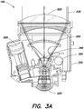
FIG. 3A is a cut-away view of one example of an afocal optical assembly for a FLIR B-kit module according to aspects of the invention; -
FIG. 3B is another view of the afocal optical assembly ofFIG. 3A ; -
FIG. 3C is another view of the afocal optical assembly ofFIGS. 3A and3B , showing the underside of the assembly according to aspects of the invention; -
FIG. 3D is an illustration of one example of an NFOV configuration of the afocal optical assembly ofFIG. 3A according to aspects of the invention; -
FIG. 3E is an illustration of one example of a WFOV configuration of the afocal optical assembly ofFIG. 3A according to aspects of the invention; -
FIG. 3F is an illustration of one example of an UWFOV configuration of the afocal optical assembly ofFIG. 3A according to aspects of the invention; -
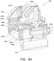
FIG. 4A is a diagram of one example of a receiver assembly with the housing removed for clarity according to aspects of the invention; -
FIG. 4B is a side view of an example of the receiver assembly ofFIG. 4A according to aspects of the invention; -
FIG. 4C is another side view of an example of the receiver assembly ofFIGS. 4A and4B according to aspects of the invention; -
FIG. 4D is a diagram of a portion of the receiver assembly ofFIGS. 4A-4C according to aspects of the invention; -
FIG. 5A is a block diagram of one example of an optical system according to aspects of the invention; and -
FIG. 5B is a block diagram of another example of an optical system according to aspects of the invention. - Aspects and embodiments are directed to a FLIR B-kit, optionally referred to as a Third Generation FLIR B-kit, which can be used to upgrade sensor systems that use existing Second Generation FLIR HTI B-kit modules. In one embodiment, the FLIR B-kit includes a set of infrared (IR) sensor modules, including one or more refractive opto-mechanical modules and electronics modules. The electronics modules may include electronic circuit card assemblies that are backward compatible with legacy Second Generation FLIR B-kits and forward compatible with Third Generation FLIR B-kits. Backward compatibility provides obsolescence mitigation to Second Generation FLIR HTI modules, and forward compatibility allows Third Generation FLIR B-kits to reuse the electronics modules while upgrading Second Generation FLIR B-kits with new features. Embodiments of the FLIR B-kit, in addition to matching field of view of the existing Second Generation FLIR HTI B-Kit, provide a field of view that provides improved sensor resolution, allowing sensor systems to achieve far greater range performance (in some examples, under good conditions, more than doubling the acquisition range compared to legacy Second Generation FLIR B-kit based sensor systems), and may provide a wider field of view, as discussed further below.
- It is to be appreciated that embodiments of the methods and apparatuses discussed herein are not limited in application to the details of construction and the arrangement of components set forth in the following description or illustrated in the accompanying drawings. The methods and apparatuses are capable of implementation in other embodiments and of being practiced or of being carried out in various ways. Examples of specific implementations are provided herein for illustrative purposes only and are not intended to be limiting. Also, the phraseology and terminology used herein is for the purpose of description and should not be regarded as limiting. The use herein of "including," "comprising," "having," "containing," "involving," and variations thereof is meant to encompass the items listed thereafter and equivalents thereof as well as additional items. References to "or" may be construed as inclusive so that any terms described using "or" may indicate any of a single, more than one, and all of the described terms.
- Referring to
FIG. 1A there is illustrated an exploded diagram of one example of a sight assembly including modules of an FLIR B-kit according to one embodiment. Thesight assembly 100 includes asight chassis 110 that housescircuit card assemblies receiver assembly 130, and an afocaloptical assembly 140. Thereceiver assembly 130 and afocaloptical assembly 140 are mounted within thechassis 110 and coupled to other components viaflexible circuit assemblies sight assembly 100 may further include an electromagneticinterference shield assembly 160. In one example, thecircuit card assembly 122 is a mechanism control circuit card assembly, and thecircuit card assemblies -
FIG. 1B illustrates an example of an assembled system 170 including element 100 (shown assembled), to include the components shown inFIG. 1A . The sight 170 further includes aslip ring assembly 180 and ahead mirror assembly 190. - According to certain examples,
elements elements -
FIG. 5A is a block diagram of one example of an optical system showing an example of the relationship between a B-Kit 500 and an A-Kit 510. The A-kit may include various structure and components used to install and operate the optical system, including, for example, gimbals (for mounting the system to a vehicle or other platform), line-of-sight controls and gyroscopes, interconnects to other systems, and user interfaces (such as controls and displays). For example, in operation of the optical system, jitter (such as may occur due to movement of the sight as it is used) can blur the image obtained. Accordingly, in one embodiment, thehead mirror assembly 190 or A-kit 510 includes a gyroscope configured to help improve image stabilization as discussed further below. - According to one embodiment, the afocal
optical assembly 140 includes anobjective lens 520 that receives incidentelectromagnetic radiation 530 and directs it into the afocal optical assembly. In one embodiment, the afocal optical assembly has a plurality of selectable fields of view implemented using a plurality of field-of-view (FOV) cells mounted on arotary turret 310 that allows a user to select between fields of view, as discussed further below. The electromagnetic radiation is directed via a selected one of the FOV cells to afocus cell 220, which directs the electromagnetic radiation to thereceiver assembly 130. Embodiments of the afocaloptical assembly 140 are discussed in more detail below with reference toFIGS. 3A - 3F . Thereceiver assembly 130 includes anoptical imager 540 which may include a plurality of lenses and/or mirrors configured to receive and focus the incomingelectromagnetic radiation 530 from thefocus cell 220 onto adetector 550. The detector may be a focal plane array, or other imaging detector. In one embodiment, particularly for infrared imaging applications, thedetector 550 is housed within aDewar 230 which may be cooled by acryogenic cooler 410. Thereceiver assembly 130 is discussed further below with reference toFIGS. 4A and4B . -
FIG. 2 illustrates an example of an assembled FLIR B-kit according to one embodiment, including the afocaloptical assembly 140 andreceiver assembly 130 assembled within thesight chassis 110. - Referring again to
FIG. 5A , as discussed above, the B-kit 500 includes one or morecircuit card assemblies circuit card assemblies 124 and/or 126 provide control and status communication, as well as video data transfer between the components of the B-kit 500 and theA-kit 510. As illustrated inFIG. 5A , the B-kit may further include a power filter andconditioner 560 that receives power from the A-kit 510 and supplies power to components of B-kit 500, as necessary, optionally viaflexible circuit assemblies 153 and 154, to thecircuit card assembly 122 and/orcircuit card assemblies 124 and/or 126. - In one embodiment, the
receiver assembly 130 includes an image motion compensation (IMC)mirror 210 that directs light from thefocus cell 220 of the afocaloptical assembly 140 through theoptical imager 540 to thedetector 550 located within theDewar 230. TheIMC mirror 210 may be used to reduce jitter and improve image stabilization. In one example, at least one of thecircuit card assemblies kit 500 includes an image motion compensation controller that is configured to compensate for error in the movement of the head mirror measured using a gyroscope, as discussed above. In certain examples, the head mirror in thehead mirror assembly 190 may be relatively large and/or heavy, and accordingly, may be limited in fine motion. Therefore, the image motion compensation controller may adjust positioning of theIMC mirror 210 based on measurements from the gyroscope to compensate for jitter and improve image stabilization and reduce blur. In addition, theIMC mirror 210 may be used to provide "backscan" which temporarily counteracts line-of-sight motion to "freeze" an image during image collection before stepping to the next image location, thereby allowing rapid wide area searching. - As discussed above, the afocal optical assembly is configured with multiple different selectable fields of view. Referring to
FIGS. 3A - 3F , in one embodiment, the afocaloptical assembly 140 includes multiple FOV cells arranged on therotatable turret 310. By rotating theturret 310, any one of the FOV cells may be aligned with thefocus cell 220 thereby achieving a selected field of view for the sight. In some examples, therotatable turret 310 is referred to as a rotating FOV wheel. In one embodiment, the afocal optical assembly has four selectable fields of view, namely an ultranarrow field of view (UNFOV), a narrow field of view (NFOV), a wide field of view (WFOV), and an ultrawide field of view (UWFOV). Other embodiments replace the UWFOV with a medium field of view (MFOV), or implement optics that support five fields of view (for example, UNFOV, NFOV, MFOV, WFOV, and UWFOV), as discussed further below. - In one embodiment, the afocal
optical assembly 140 includes aWFOV cell 330, aUWFOV cell 320, and aUNFOV cell 340. In one example the optical system has a field of view of approximately 1.24 degrees horizontal by 0.7 degrees vertical in the UNFOV configuration (i.e., with theUNFOV cell 340 aligned with the focus cell 220). In another example, the optical system has a field of view of approximately 13.3 degrees horizontal by 7.5 degrees vertical in the WFOV configuration. In another example, the optical system has a field of view of approximately 21.9 degrees horizontal by 12.3 degrees vertical in the UWFOV configuration. In some examples the optical system may have a field of view of approximately 3.56 degrees horizontal by 2.0 degrees vertical in the NFOV configuration, and a field of view of approximately 7.1 degrees horizontal by 4 degrees vertical in the MFOV configuration. - In one example, the optical parameters and design of the afocal
optical assembly 140 uses the NFOV configuration as the basis for the optical design. Accordingly, in one example, the FOV wheel has an opening and does not include any lenses, so that theobjective lenses 520, focus lens cell, and "downstream" optical components define the NFOV. In some embodiments, aflip lens 350 may be used for the UNFOV configuration. As illustrated inFIGS. 3A and3B , in one embodiment, theflip lens 350 may be configured to be movable into and out of the optical path over theUNFOV cell 340.FIGS. 3A and3B show thelens 350 flipped into the optical path. In each of these configurations, the rotatingFOV wheel 310 is positioned such that theUNFOV cell 340 is aligned over thefocus cell 220 or "eyepiece" of the afocaloptical assembly 140. Anactuator assembly 355 may be used to effect the movement of theflip lens 350. Thus, to achieve UNFOV operation, the UNFOV cell and theflip lens 350 are positioned in the NFOV optical path, aligned with thefocus cell 220. -
FIGS. 3D-3F illustrate configurations of the afocaloptical assembly 140 for different fields of view.FIG. 3D illustrates an example of the NFOV configuration, in which theflip lens 350 is positioned out of the optical path, and an "empty" slot on thestructure 310 is positioned over thefocus cell 220 since, as discussed above, in this example the NFOV configuration forms the basis for the optical design.FIG. 3E illustrates an example of the WFOV configuration in which theflip lens 350 is positioned out of the optical path, and thestructure 310 is rotated such that theWFOV cell 330 is positioned in the optical path aligned with thefocus cell 220.FIG. 3F illustrates an example of the UWFOV configuration in which theflip lens 350 is positioned out of the optical path, and thestructure 310 is rotated such that theUWFOV cell 320 is positioned in the optical path aligned with thefocus cell 220. - In one embodiment, the afocal
optical assembly 140 is a fully refractive optical system (optionally excluding planar fold mirrors as discussed further below) to provide a compact optical assembly which may be accommodated within the space allocated to legacy optical assemblies in existing systems. In other embodiments the afocal assembly utilizes a combination of reflective and refractive lenses which, while may not be easily packaged into some A-Kits, may be more optimal for others. - According to one embodiment, the afocal
optical assembly 140 may also include athermal reference source 360 positioned on therotating FOV wheel 310. Thethermal reference source 360 may be configured to produce infrared radiation having known characteristics (e.g., predetermined spectral characteristics and intensity). For thermal calibration of the afocaloptical assembly 140, and/or other components of the sight assembly, thethermal reference source 360 may be rotated into alignment with thefocus cell 220 such that the known radiation is supplied to the detector in thereceiver assembly 130. Measurements from the detector of thethermal reference source 360 may be used to calibrate the sensor. - In one example, the thermal reference source (TRS) 360 includes a thermal electric cooler (TEC) and optics to produce a uniform image which may be used for non-uniformity correction. Including the
thermal reference source 360 on therotary turret 310 removes the need for a separate mechanism to insert the thermal reference source. When inserted and active, thethermal reference source 360 provides a uniform thermal image that is imaged onto all of the detector elements of thedetector 550. When viewing a uniform image the output of all detectors should be the same. Non-uniformity correction measures the differences in detector outputs for at least two different thermal electric cooler temperatures to generate coefficients that are used to electronically adjust the video from each detector element such that when viewing the same intensity within an image each detector element provides the same output. - In one embodiment when the thermal reference source is placed over the
focus cell 220 it acts as a shutter, blocking external electro-magnetic radiation from reaching thedetector 550, thereby protecting the detector and the smaller focus and imager lenses from damage. - In one embodiment, the afocal optical assembly is configured for mid-wave infrared (MWIR) and long-wave infrared (LWIR) imaging. Accordingly, all lenses are designed having materials and parameters suitable for transmission of electromagnetic radiation in the MWIR and LWIR spectral bands. For example, the optics may be configured for transmission over a wavelength range of approximately 3-5 µm and 8-12 µm. Some example materials which may be used to produce optical components, such as lenses, operable over at least a portion of these wavelength ranges may include Gallium Arsenide (GaAs), Barium Fluoride (BaF2), Zinc Selenide (ZnSe), Zinc Sulfide (ZnS), and Germanium (Ge), among others. Chalcogenide materials (germanium, selenium, arsenic compounds) may also be used if not prohibited.
- Still referring to
FIGS. 3A-F , components of the afocaloptical assembly 140 may be accommodated within ahousing 370 configured to fit within and be mounted within thechassis 110 discussed above. Aconnector 380 may be provided to connect components, such as theactuator assembly 355 for theflip mirror 350, and actuator for therotating FOV wheel 310, or thethermal reference source 360 to one or more of thecircuit card assemblies - As discussed above, according to certain embodiments, the sight assembly further includes the
receiver assembly 130. An example of thereceiver assembly 130 is illustrated in more detail inFIGS. 4A - 4D . In one embodiment, thereceiver assembly 130 includes a cooledimaging detector 550 packaged in theDewar 230. In one example, theimaging detector 550 is a two-dimensional (2D) array detector, such as a 2D focal plane array. In contrast, the Second Generation FLIR B-kits include only a one-dimensional detector array. Thedetector Dewar 230 includes awindow 415 that allows electromagnetic radiation into the Dewar to reach thedetector array 550. Acryogenic cooler 410 may provide the cooling of theDewar 230. Cold shielding of thedetector array 550 within theDewar 230 provided by the variable aperture mechanism is advantageous in that it blocks stray "light" from hitting the detector, reducing noise which otherwise can greatly reduce the sensitivity (and therefore range) of a thermal imaging detector. Acooler control module 425 may control operation of the cooler 410, such as the temperature to which theDewar 230 is cooled, for example. Thecooler control module 425 may be coupled to one or more of thecircuit card assemblies - Referring to
FIGS. 4C ,4D and5A , thereceiver assembly 130 may includeinterface electronics 450. Theinterface electronics 450 may be coupled to, one or more of thecircuit card assemblies heat transfer strap 460 is connector between theinterface electronics 450 and the receiver base to transfer heat away from the electronics. - In one embodiment, the
Dewar 230 includes a variable aperture mechanism (VAM) packaged within theDewar 230 that provides an "f-stop" for the optics. In one example, this variable aperture mechanism has two or more positions that set the f/# for the optical system. In one example, the detector Dewar includes a dual f/# variable aperture mechanism that provides low f/# (for example, about f/2.0 or f/2.5) full LWIR performance in the NFOV, WFOV, MFOV and UWFOV configurations, while also providing a higher f/# (for example, between about f/4.0 and f/6.0; in one example, f/5.06) for the long effective focal length (EFL) UNFOV configuration to increase the range of the sight. In one example, the NFOV and WFOV have the same dimensions as the Second Generation FLIR B-Kit NFOV and WFOV but provide performance that exceeds that of a comparable Second Generation FLIR B-kit optical module under substantially all operating conditions. - Referring again to
FIGS. 4A and5A , theoptical imager 540 of thereceiver assembly 130 may include a configuration of mirrors and lenses to direct the incoming electromagnetic radiation from thefocus cell 220 of the afocaloptical assembly 140 into theDewar 230. These mirrors and lenses may be selected and arranged to achieve a compact form factor for thereceiver assembly 130. In the example illustrated inFIG. 4A , theimager 540 includes a pair of fold mirrors 420 and a set of eight lenses 430a-h. The lenses may be configured and grouped, for example, in pairs with a positive-power and negative-power or zero-power lens in each pair as shown inFIG. 4A , to achieve color correction over a wide spectral band, such as from approximately 3 - 5 µm and 7.6 - 10 µm, for example. - In one embodiment, the receiver assembly includes a
filter wheel 440 positioned between thelenses FIG. 4A . It will be appreciated that although thefilter wheel 440 is illustrated positioned betweenlenses focus cell 220 and thedetector 550. - As discussed above, the afocal optical assembly may be configured to provide a number of different fields of view. In one embodiment, as discussed with reference to
FIGS. 3A - 3F , the afocal optical assembly includes theUWFOV cell 320,WFOV cell 330, andUNFOV cell 340. Referring toFIG. 5B , in another embodiment, theUNFOV cell 340 is replaced with aMFOV cell 390. In this embodiment, theoptical imager 540 of thereceiver assembly 130 may include aFOV mechanism 570 to provide additional fields of view, such as for a 5 FOV sensor. For example, the FOV mechanism may include one or more lenses or other optical components that may be movable into or out of the optical path between thefocus cell 220 and thedetector 550 to change the field of the view of the system, for example, between a narrow field of view and an ultranarrow field of view. In one example of this embodiment, theflip lens 350 is eliminated. This configuration may be advantageous in that it may provide improved boresight retention and/or reduced UNFOV switch time, along with reduced size, weight and power (SWAP) characteristics for the sight. - Having described above several aspects of at least one embodiment, it is to be appreciated various alterations, modifications, and improvements will readily occur to those skilled in the art. Such alterations, modifications, and improvements are intended to be part of this disclosure and are intended to be within the scope of the invention.
Claims (12)
- An infrared imaging sensor (100) compatible with upgrade of second generation forward looking infrared (FLIR) B-kits, comprising:a set of refractive opto-mechanical modules configured to receive and create video from infrared electromagnetic radiation in at least the mid-wave infrared (MWIR) and long-wave infrared (LWIR) spectral bands, the set of refractive opto-mechanical modules including an afocal optical module (140) having an eyepiece, wherein the eyepiece is a focus cell for the sensor, the afocal optical module being configured to receive and magnify the electromagnetic radiation in the MWIR and LWIR spectral bands and to output magnified electromagnetic radiation via the focus cell (220) and configured to provide a plurality of different fields of view for the infrared imaging sensor, said afocal optical module (140) comprising a plurality of field of view (FOV) cells (320, 330, 340), each configured to provide one of the plurality of fields of view;a receiver assembly (130) including a detector (550) in a Dewar (230) optically coupled to the focus cell (220) and configured to receive the infrared electromagnetic radiation from the focus cell (220) and to generate an electronic image from the infrared electromagnetic radiation; andat least one electronics module (450) configured to provide an electronic interface for the infrared imaging sensor, and to process the electronic image; and characterized in that:
the plurality of FOV cells (320, 330, 340) are disposed on a rotating structure (310) that is configured to rotate with respect to the focus cell (220) so as to align one of the plurality of FOV cells (320, 330, 340) with the focus cell (220); and further characterized by:
a thermal reference source (360) disposed on the rotating structure (310), wherein the thermal reference source (360) is configured to be moved into an optical path of the focus cell (220) and to provide a shutter mechanism for the sensor. - The infrared imaging sensor (100) of claim 1, wherein the afocal optical module (140) is configured to provide at least four fields of view.
- The infrared imaging sensor (100) of claim 2, wherein the at least four fields of view include an ultranarrow field of view, a narrow field of view, a wide field of view, and an ultrawide field of view.
- The infrared imaging sensor (100) of claim 3, wherein the at least four fields of view includes five fields of view, further including a medium field of view.
- The infrared imaging sensor (100) of claim 4, wherein the receiver assembly (130) includes a FOV mechanism configured to switch the field of view of the sensor between the ultranarrow field of view and the narrow field of view without changing a position of the afocal optical module (140).
- The infrared imaging sensor (100) of claim 2, wherein the at least four fields of view include an ultranarrow field of view, a narrow field of view, a medium field of view, and a wide field of view.
- The infrared imaging sensor (100) of claim 1, wherein the afocal optical module further comprises a movable lens that is movable into and out of an optical path between an input aperture of the afocal optical module and at least one of the plurality of FOV cells.
- The infrared imaging sensor (100) of claim 1, wherein the Dewar includes a dual f/# variable aperture mechanism configured to provide a first f/# for at least a first one of the plurality of fields of view, and a second f/# for at least a second one of the plurality of fields of view.
- The infrared imaging system (100) of claim 1, wherein the receiver assembly (130) further includes an imager (540) configured to direct the infrared electromagnetic radiation from the afocal optical module (140) to the detector (550) in the Dewar (230).
- The infrared imaging sensor (100) of claim 9, wherein the receiver assembly (130) further includes an image motion compensation mirror.
- The infrared imaging sensor (100) of claim 10, wherein the image motion compensation mirror is configured for backscan imaging.
- The infrared imaging system (100) of claim 1, wherein the detector (550) is a two-dimensional focal plane array.
Applications Claiming Priority (3)
| Application Number | Priority Date | Filing Date | Title |
|---|---|---|---|
| US201261666239P | 2012-06-29 | 2012-06-29 | |
| US13/712,276 US9225914B2 (en) | 2012-06-29 | 2012-12-12 | Infrared imaging system |
| PCT/US2013/038772 WO2014014547A2 (en) | 2012-06-29 | 2013-04-30 | Infrared imaging system |
Publications (2)
| Publication Number | Publication Date |
|---|---|
| EP2867713A2 EP2867713A2 (en) | 2015-05-06 |
| EP2867713B1 true EP2867713B1 (en) | 2019-10-16 |
Family
ID=49777758
Family Applications (1)
| Application Number | Title | Priority Date | Filing Date |
|---|---|---|---|
| EP13795314.7A Active EP2867713B1 (en) | 2012-06-29 | 2013-04-30 | Infrared imaging system |
Country Status (4)
| Country | Link |
|---|---|
| US (1) | US9225914B2 (en) |
| EP (1) | EP2867713B1 (en) |
| TW (1) | TWI587001B (en) |
| WO (1) | WO2014014547A2 (en) |
Families Citing this family (8)
| Publication number | Priority date | Publication date | Assignee | Title |
|---|---|---|---|---|
| US9207434B2 (en) * | 2014-02-25 | 2015-12-08 | Bae Systems Information And Electronic Systems Integration Inc. | Dual-band passively athermal optical lens system |
| US10095008B1 (en) * | 2015-11-24 | 2018-10-09 | Lockhead Martin Corporation | Lens assembly with switched ultra-narrow field-of-view configuration |
| US10003751B2 (en) | 2016-05-25 | 2018-06-19 | The United States Of America, As Represented By The Secretary Of The Army | Multiple field of view dual band optics with integrated calibration source |
| USD871412S1 (en) * | 2016-11-21 | 2019-12-31 | Datalogic Ip Tech S.R.L. | Optical scanner |
| US10533901B2 (en) | 2017-06-06 | 2020-01-14 | General Electric Company | Imaging system for inspecting components of turbomachines and method of assembly thereof |
| US10509210B2 (en) * | 2017-08-14 | 2019-12-17 | Raytheon Company | Two-color very wide field of view refractive eyepiece-type optical form |
| US11402401B2 (en) * | 2018-08-29 | 2022-08-02 | Drs Network & Imaging Systems, Llc | Method and system for scanning of a transparent plate during earth observation imaging |
| CN110989138B (en) * | 2019-12-23 | 2021-03-19 | 中国科学院长春光学精密机械与物理研究所 | Wide spectrum afocal optical system with large field of view |
Citations (2)
| Publication number | Priority date | Publication date | Assignee | Title |
|---|---|---|---|---|
| US6226125B1 (en) * | 1999-08-19 | 2001-05-01 | Raytheon Company | Electro-optical system having a ball turret and an exterior thermal reference source |
| US20070086087A1 (en) * | 2005-10-14 | 2007-04-19 | Dent Gregory D | Multiple field of view optical system |
Family Cites Families (8)
| Publication number | Priority date | Publication date | Assignee | Title |
|---|---|---|---|---|
| US5510618A (en) | 1994-06-23 | 1996-04-23 | The United States Of America As Represented By The Secretary Of The Army | Second generation FLIR common modules |
| US5477395A (en) | 1994-11-14 | 1995-12-19 | Hughes Aircraft Company | Two nested all-reflective afocal telescopes providing four fields of view |
| US5936771A (en) | 1997-07-31 | 1999-08-10 | Raytheon Company | Compact flir optical configuration |
| US6274868B1 (en) | 1997-07-23 | 2001-08-14 | The United States Of America As Represented By The Secretary Of The Army | All purpose FLIR kit for aircraft |
| US6310345B1 (en) | 1999-10-12 | 2001-10-30 | The United States Of America As Represented By The Secretary Of The Army | Polarization-resolving infrared imager |
| US7118217B2 (en) * | 2002-01-18 | 2006-10-10 | University Of Iowa Research Foundation | Device and method for optical imaging of retinal function |
| US7237098B2 (en) * | 2003-09-08 | 2007-06-26 | Ip-First, Llc | Apparatus and method for selectively overriding return stack prediction in response to detection of non-standard return sequence |
| US20070001094A1 (en) * | 2005-06-29 | 2007-01-04 | Micron Technology, Inc. | Infrared filter for imagers |
-
2012
- 2012-12-12 US US13/712,276 patent/US9225914B2/en active Active
-
2013
- 2013-04-30 EP EP13795314.7A patent/EP2867713B1/en active Active
- 2013-04-30 WO PCT/US2013/038772 patent/WO2014014547A2/en active Application Filing
- 2013-05-02 TW TW102115692A patent/TWI587001B/en active
Patent Citations (2)
| Publication number | Priority date | Publication date | Assignee | Title |
|---|---|---|---|---|
| US6226125B1 (en) * | 1999-08-19 | 2001-05-01 | Raytheon Company | Electro-optical system having a ball turret and an exterior thermal reference source |
| US20070086087A1 (en) * | 2005-10-14 | 2007-04-19 | Dent Gregory D | Multiple field of view optical system |
Also Published As
| Publication number | Publication date |
|---|---|
| TWI587001B (en) | 2017-06-11 |
| WO2014014547A2 (en) | 2014-01-23 |
| EP2867713A2 (en) | 2015-05-06 |
| US9225914B2 (en) | 2015-12-29 |
| US20140002665A1 (en) | 2014-01-02 |
| TW201400856A (en) | 2014-01-01 |
| WO2014014547A3 (en) | 2014-03-13 |
Similar Documents
| Publication | Publication Date | Title |
|---|---|---|
| EP2867713B1 (en) | Infrared imaging system | |
| ES2211154T3 (en) | MULTIFUNCTIONAL, MULTIESPECTRAL, INTEGRATED AND METHOD SET. | |
| EP3172524B1 (en) | Combination video and optical sight | |
| US11402271B2 (en) | Extensible architecture for surveillance and targeting imaging systems and methods | |
| US6646799B1 (en) | System and method for combining multiple energy bands to improve scene viewing | |
| US20180267282A1 (en) | Wide spectrum optical systems and devices implementing first surface mirrors | |
| US7755047B2 (en) | Clip-on infrared imager | |
| US9200966B2 (en) | Dual field of view telescope | |
| US11092796B2 (en) | Long range infrared imager systems and methods | |
| US20120007987A1 (en) | Optical system with automatic switching between operation in daylight and thermovision modes | |
| EP3004958B1 (en) | Optical configuration for a compact integrated day/night viewing and laser range finding system | |
| EP3401631B1 (en) | Thermal reflex sight | |
| US9110276B2 (en) | Full-field GEO imager optics with extended spectral coverage | |
| WO2011100674A1 (en) | Improved optical image system | |
| US20160062133A1 (en) | Optics system with magnetic backlash reduction | |
| CN114341693A (en) | Afocal attachment for a telescope | |
| Breiter et al. | AIM thermal imagers for reconnaissance and targeting applications | |
| Seibel et al. | Long range handheld thermal imager | |
| Bryant | Head-mounted common aperture LWIR and SWIR optics |
Legal Events
| Date | Code | Title | Description |
|---|---|---|---|
| PUAI | Public reference made under article 153(3) epc to a published international application that has entered the european phase |
Free format text: ORIGINAL CODE: 0009012 |
|
| 17P | Request for examination filed |
Effective date: 20141212 |
|
| AK | Designated contracting states |
Kind code of ref document: A2 Designated state(s): AL AT BE BG CH CY CZ DE DK EE ES FI FR GB GR HR HU IE IS IT LI LT LU LV MC MK MT NL NO PL PT RO RS SE SI SK SM TR |
|
| AX | Request for extension of the european patent |
Extension state: BA ME |
|
| RIN1 | Information on inventor provided before grant (corrected) |
Inventor name: KINGDON, FREDERIC, W. Inventor name: MARKASON, DAVID, J. Inventor name: STROTHER, GEORGE, T. Inventor name: FOLEY, MICHAEL, G. Inventor name: ERNEST, MICHAEL, D. Inventor name: JUERGENS, RICHARD, C. |
|
| DAX | Request for extension of the european patent (deleted) | ||
| STAA | Information on the status of an ep patent application or granted ep patent |
Free format text: STATUS: EXAMINATION IS IN PROGRESS |
|
| 17Q | First examination report despatched |
Effective date: 20181008 |
|
| GRAP | Despatch of communication of intention to grant a patent |
Free format text: ORIGINAL CODE: EPIDOSNIGR1 |
|
| STAA | Information on the status of an ep patent application or granted ep patent |
Free format text: STATUS: GRANT OF PATENT IS INTENDED |
|
| INTG | Intention to grant announced |
Effective date: 20190509 |
|
| GRAS | Grant fee paid |
Free format text: ORIGINAL CODE: EPIDOSNIGR3 |
|
| GRAA | (expected) grant |
Free format text: ORIGINAL CODE: 0009210 |
|
| STAA | Information on the status of an ep patent application or granted ep patent |
Free format text: STATUS: THE PATENT HAS BEEN GRANTED |
|
| AK | Designated contracting states |
Kind code of ref document: B1 Designated state(s): AL AT BE BG CH CY CZ DE DK EE ES FI FR GB GR HR HU IE IS IT LI LT LU LV MC MK MT NL NO PL PT RO RS SE SI SK SM TR |
|
| REG | Reference to a national code |
Ref country code: GB Ref legal event code: FG4D |
|
| REG | Reference to a national code |
Ref country code: CH Ref legal event code: EP |
|
| REG | Reference to a national code |
Ref country code: DE Ref legal event code: R096 Ref document number: 602013061805 Country of ref document: DE |
|
| REG | Reference to a national code |
Ref country code: IE Ref legal event code: FG4D |
|
| REG | Reference to a national code |
Ref country code: AT Ref legal event code: REF Ref document number: 1191838 Country of ref document: AT Kind code of ref document: T Effective date: 20191115 |
|
| REG | Reference to a national code |
Ref country code: NL Ref legal event code: MP Effective date: 20191016 |
|
| REG | Reference to a national code |
Ref country code: LT Ref legal event code: MG4D |
|
| REG | Reference to a national code |
Ref country code: AT Ref legal event code: MK05 Ref document number: 1191838 Country of ref document: AT Kind code of ref document: T Effective date: 20191016 |
|
| PG25 | Lapsed in a contracting state [announced via postgrant information from national office to epo] |
Ref country code: ES Free format text: LAPSE BECAUSE OF FAILURE TO SUBMIT A TRANSLATION OF THE DESCRIPTION OR TO PAY THE FEE WITHIN THE PRESCRIBED TIME-LIMIT Effective date: 20191016 Ref country code: PT Free format text: LAPSE BECAUSE OF FAILURE TO SUBMIT A TRANSLATION OF THE DESCRIPTION OR TO PAY THE FEE WITHIN THE PRESCRIBED TIME-LIMIT Effective date: 20200217 Ref country code: AT Free format text: LAPSE BECAUSE OF FAILURE TO SUBMIT A TRANSLATION OF THE DESCRIPTION OR TO PAY THE FEE WITHIN THE PRESCRIBED TIME-LIMIT Effective date: 20191016 Ref country code: LT Free format text: LAPSE BECAUSE OF FAILURE TO SUBMIT A TRANSLATION OF THE DESCRIPTION OR TO PAY THE FEE WITHIN THE PRESCRIBED TIME-LIMIT Effective date: 20191016 Ref country code: PL Free format text: LAPSE BECAUSE OF FAILURE TO SUBMIT A TRANSLATION OF THE DESCRIPTION OR TO PAY THE FEE WITHIN THE PRESCRIBED TIME-LIMIT Effective date: 20191016 Ref country code: GR Free format text: LAPSE BECAUSE OF FAILURE TO SUBMIT A TRANSLATION OF THE DESCRIPTION OR TO PAY THE FEE WITHIN THE PRESCRIBED TIME-LIMIT Effective date: 20200117 Ref country code: BG Free format text: LAPSE BECAUSE OF FAILURE TO SUBMIT A TRANSLATION OF THE DESCRIPTION OR TO PAY THE FEE WITHIN THE PRESCRIBED TIME-LIMIT Effective date: 20200116 Ref country code: NL Free format text: LAPSE BECAUSE OF FAILURE TO SUBMIT A TRANSLATION OF THE DESCRIPTION OR TO PAY THE FEE WITHIN THE PRESCRIBED TIME-LIMIT Effective date: 20191016 Ref country code: FI Free format text: LAPSE BECAUSE OF FAILURE TO SUBMIT A TRANSLATION OF THE DESCRIPTION OR TO PAY THE FEE WITHIN THE PRESCRIBED TIME-LIMIT Effective date: 20191016 Ref country code: LV Free format text: LAPSE BECAUSE OF FAILURE TO SUBMIT A TRANSLATION OF THE DESCRIPTION OR TO PAY THE FEE WITHIN THE PRESCRIBED TIME-LIMIT Effective date: 20191016 Ref country code: SE Free format text: LAPSE BECAUSE OF FAILURE TO SUBMIT A TRANSLATION OF THE DESCRIPTION OR TO PAY THE FEE WITHIN THE PRESCRIBED TIME-LIMIT Effective date: 20191016 Ref country code: NO Free format text: LAPSE BECAUSE OF FAILURE TO SUBMIT A TRANSLATION OF THE DESCRIPTION OR TO PAY THE FEE WITHIN THE PRESCRIBED TIME-LIMIT Effective date: 20200116 |
|
| PG25 | Lapsed in a contracting state [announced via postgrant information from national office to epo] |
Ref country code: HR Free format text: LAPSE BECAUSE OF FAILURE TO SUBMIT A TRANSLATION OF THE DESCRIPTION OR TO PAY THE FEE WITHIN THE PRESCRIBED TIME-LIMIT Effective date: 20191016 Ref country code: RS Free format text: LAPSE BECAUSE OF FAILURE TO SUBMIT A TRANSLATION OF THE DESCRIPTION OR TO PAY THE FEE WITHIN THE PRESCRIBED TIME-LIMIT Effective date: 20191016 Ref country code: IS Free format text: LAPSE BECAUSE OF FAILURE TO SUBMIT A TRANSLATION OF THE DESCRIPTION OR TO PAY THE FEE WITHIN THE PRESCRIBED TIME-LIMIT Effective date: 20200224 |
|
| PG25 | Lapsed in a contracting state [announced via postgrant information from national office to epo] |
Ref country code: AL Free format text: LAPSE BECAUSE OF FAILURE TO SUBMIT A TRANSLATION OF THE DESCRIPTION OR TO PAY THE FEE WITHIN THE PRESCRIBED TIME-LIMIT Effective date: 20191016 |
|
| REG | Reference to a national code |
Ref country code: DE Ref legal event code: R097 Ref document number: 602013061805 Country of ref document: DE |
|
| PG2D | Information on lapse in contracting state deleted |
Ref country code: IS |
|
| PG25 | Lapsed in a contracting state [announced via postgrant information from national office to epo] |
Ref country code: EE Free format text: LAPSE BECAUSE OF FAILURE TO SUBMIT A TRANSLATION OF THE DESCRIPTION OR TO PAY THE FEE WITHIN THE PRESCRIBED TIME-LIMIT Effective date: 20191016 Ref country code: CZ Free format text: LAPSE BECAUSE OF FAILURE TO SUBMIT A TRANSLATION OF THE DESCRIPTION OR TO PAY THE FEE WITHIN THE PRESCRIBED TIME-LIMIT Effective date: 20191016 Ref country code: RO Free format text: LAPSE BECAUSE OF FAILURE TO SUBMIT A TRANSLATION OF THE DESCRIPTION OR TO PAY THE FEE WITHIN THE PRESCRIBED TIME-LIMIT Effective date: 20191016 Ref country code: DK Free format text: LAPSE BECAUSE OF FAILURE TO SUBMIT A TRANSLATION OF THE DESCRIPTION OR TO PAY THE FEE WITHIN THE PRESCRIBED TIME-LIMIT Effective date: 20191016 Ref country code: IS Free format text: LAPSE BECAUSE OF FAILURE TO SUBMIT A TRANSLATION OF THE DESCRIPTION OR TO PAY THE FEE WITHIN THE PRESCRIBED TIME-LIMIT Effective date: 20200216 |
|
| PLBE | No opposition filed within time limit |
Free format text: ORIGINAL CODE: 0009261 |
|
| STAA | Information on the status of an ep patent application or granted ep patent |
Free format text: STATUS: NO OPPOSITION FILED WITHIN TIME LIMIT |
|
| PG25 | Lapsed in a contracting state [announced via postgrant information from national office to epo] |
Ref country code: SK Free format text: LAPSE BECAUSE OF FAILURE TO SUBMIT A TRANSLATION OF THE DESCRIPTION OR TO PAY THE FEE WITHIN THE PRESCRIBED TIME-LIMIT Effective date: 20191016 Ref country code: SM Free format text: LAPSE BECAUSE OF FAILURE TO SUBMIT A TRANSLATION OF THE DESCRIPTION OR TO PAY THE FEE WITHIN THE PRESCRIBED TIME-LIMIT Effective date: 20191016 Ref country code: IT Free format text: LAPSE BECAUSE OF FAILURE TO SUBMIT A TRANSLATION OF THE DESCRIPTION OR TO PAY THE FEE WITHIN THE PRESCRIBED TIME-LIMIT Effective date: 20191016 |
|
| 26N | No opposition filed |
Effective date: 20200717 |
|
| PG25 | Lapsed in a contracting state [announced via postgrant information from national office to epo] |
Ref country code: SI Free format text: LAPSE BECAUSE OF FAILURE TO SUBMIT A TRANSLATION OF THE DESCRIPTION OR TO PAY THE FEE WITHIN THE PRESCRIBED TIME-LIMIT Effective date: 20191016 Ref country code: MC Free format text: LAPSE BECAUSE OF FAILURE TO SUBMIT A TRANSLATION OF THE DESCRIPTION OR TO PAY THE FEE WITHIN THE PRESCRIBED TIME-LIMIT Effective date: 20191016 |
|
| REG | Reference to a national code |
Ref country code: CH Ref legal event code: PL |
|
| PG25 | Lapsed in a contracting state [announced via postgrant information from national office to epo] |
Ref country code: CH Free format text: LAPSE BECAUSE OF NON-PAYMENT OF DUE FEES Effective date: 20200430 Ref country code: LU Free format text: LAPSE BECAUSE OF NON-PAYMENT OF DUE FEES Effective date: 20200430 Ref country code: LI Free format text: LAPSE BECAUSE OF NON-PAYMENT OF DUE FEES Effective date: 20200430 |
|
| REG | Reference to a national code |
Ref country code: BE Ref legal event code: MM Effective date: 20200430 |
|
| PG25 | Lapsed in a contracting state [announced via postgrant information from national office to epo] |
Ref country code: BE Free format text: LAPSE BECAUSE OF NON-PAYMENT OF DUE FEES Effective date: 20200430 |
|
| PG25 | Lapsed in a contracting state [announced via postgrant information from national office to epo] |
Ref country code: IE Free format text: LAPSE BECAUSE OF NON-PAYMENT OF DUE FEES Effective date: 20200430 |
|
| PG25 | Lapsed in a contracting state [announced via postgrant information from national office to epo] |
Ref country code: TR Free format text: LAPSE BECAUSE OF FAILURE TO SUBMIT A TRANSLATION OF THE DESCRIPTION OR TO PAY THE FEE WITHIN THE PRESCRIBED TIME-LIMIT Effective date: 20191016 Ref country code: MT Free format text: LAPSE BECAUSE OF FAILURE TO SUBMIT A TRANSLATION OF THE DESCRIPTION OR TO PAY THE FEE WITHIN THE PRESCRIBED TIME-LIMIT Effective date: 20191016 Ref country code: CY Free format text: LAPSE BECAUSE OF FAILURE TO SUBMIT A TRANSLATION OF THE DESCRIPTION OR TO PAY THE FEE WITHIN THE PRESCRIBED TIME-LIMIT Effective date: 20191016 |
|
| PG25 | Lapsed in a contracting state [announced via postgrant information from national office to epo] |
Ref country code: MK Free format text: LAPSE BECAUSE OF FAILURE TO SUBMIT A TRANSLATION OF THE DESCRIPTION OR TO PAY THE FEE WITHIN THE PRESCRIBED TIME-LIMIT Effective date: 20191016 |
|
| PGFP | Annual fee paid to national office [announced via postgrant information from national office to epo] |
Ref country code: FR Payment date: 20230321 Year of fee payment: 11 |
|
| P01 | Opt-out of the competence of the unified patent court (upc) registered |
Effective date: 20230530 |
|
| PGFP | Annual fee paid to national office [announced via postgrant information from national office to epo] |
Ref country code: DE Payment date: 20230321 Year of fee payment: 11 |
|
| PGFP | Annual fee paid to national office [announced via postgrant information from national office to epo] |
Ref country code: GB Payment date: 20240320 Year of fee payment: 12 |