EP2866857B1 - Spring driven injection device - Google Patents
Spring driven injection device Download PDFInfo
- Publication number
- EP2866857B1 EP2866857B1 EP13731143.7A EP13731143A EP2866857B1 EP 2866857 B1 EP2866857 B1 EP 2866857B1 EP 13731143 A EP13731143 A EP 13731143A EP 2866857 B1 EP2866857 B1 EP 2866857B1
- Authority
- EP
- European Patent Office
- Prior art keywords
- needle
- shield
- injection
- dose
- scale drum
- Prior art date
- Legal status (The legal status is an assumption and is not a legal conclusion. Google has not performed a legal analysis and makes no representation as to the accuracy of the status listed.)
- Not-in-force
Links
Images


Classifications
-
- A—HUMAN NECESSITIES
- A61—MEDICAL OR VETERINARY SCIENCE; HYGIENE
- A61M—DEVICES FOR INTRODUCING MEDIA INTO, OR ONTO, THE BODY; DEVICES FOR TRANSDUCING BODY MEDIA OR FOR TAKING MEDIA FROM THE BODY; DEVICES FOR PRODUCING OR ENDING SLEEP OR STUPOR
- A61M5/00—Devices for bringing media into the body in a subcutaneous, intra-vascular or intramuscular way; Accessories therefor, e.g. filling or cleaning devices, arm-rests
- A61M5/178—Syringes
- A61M5/20—Automatic syringes, e.g. with automatically actuated piston rod, with automatic needle injection, filling automatically
- A61M5/2033—Spring-loaded one-shot injectors with or without automatic needle insertion
-
- A—HUMAN NECESSITIES
- A61—MEDICAL OR VETERINARY SCIENCE; HYGIENE
- A61M—DEVICES FOR INTRODUCING MEDIA INTO, OR ONTO, THE BODY; DEVICES FOR TRANSDUCING BODY MEDIA OR FOR TAKING MEDIA FROM THE BODY; DEVICES FOR PRODUCING OR ENDING SLEEP OR STUPOR
- A61M5/00—Devices for bringing media into the body in a subcutaneous, intra-vascular or intramuscular way; Accessories therefor, e.g. filling or cleaning devices, arm-rests
- A61M5/178—Syringes
- A61M5/31—Details
- A61M5/315—Pistons; Piston-rods; Guiding, blocking or restricting the movement of the rod or piston; Appliances on the rod for facilitating dosing ; Dosing mechanisms
- A61M5/31533—Dosing mechanisms, i.e. setting a dose
- A61M5/31535—Means improving security or handling thereof, e.g. blocking means, means preventing insufficient dosing, means allowing correction of overset dose
- A61M5/31541—Means preventing setting of a dose beyond the amount remaining in the cartridge
-
- A—HUMAN NECESSITIES
- A61—MEDICAL OR VETERINARY SCIENCE; HYGIENE
- A61M—DEVICES FOR INTRODUCING MEDIA INTO, OR ONTO, THE BODY; DEVICES FOR TRANSDUCING BODY MEDIA OR FOR TAKING MEDIA FROM THE BODY; DEVICES FOR PRODUCING OR ENDING SLEEP OR STUPOR
- A61M5/00—Devices for bringing media into the body in a subcutaneous, intra-vascular or intramuscular way; Accessories therefor, e.g. filling or cleaning devices, arm-rests
- A61M5/178—Syringes
- A61M5/31—Details
- A61M5/315—Pistons; Piston-rods; Guiding, blocking or restricting the movement of the rod or piston; Appliances on the rod for facilitating dosing ; Dosing mechanisms
- A61M5/31533—Dosing mechanisms, i.e. setting a dose
- A61M5/31545—Setting modes for dosing
- A61M5/31548—Mechanically operated dose setting member
- A61M5/3155—Mechanically operated dose setting member by rotational movement of dose setting member, e.g. during setting or filling of a syringe
- A61M5/31553—Mechanically operated dose setting member by rotational movement of dose setting member, e.g. during setting or filling of a syringe without axial movement of dose setting member
-
- A—HUMAN NECESSITIES
- A61—MEDICAL OR VETERINARY SCIENCE; HYGIENE
- A61M—DEVICES FOR INTRODUCING MEDIA INTO, OR ONTO, THE BODY; DEVICES FOR TRANSDUCING BODY MEDIA OR FOR TAKING MEDIA FROM THE BODY; DEVICES FOR PRODUCING OR ENDING SLEEP OR STUPOR
- A61M5/00—Devices for bringing media into the body in a subcutaneous, intra-vascular or intramuscular way; Accessories therefor, e.g. filling or cleaning devices, arm-rests
- A61M5/178—Syringes
- A61M5/31—Details
- A61M5/315—Pistons; Piston-rods; Guiding, blocking or restricting the movement of the rod or piston; Appliances on the rod for facilitating dosing ; Dosing mechanisms
- A61M5/31565—Administration mechanisms, i.e. constructional features, modes of administering a dose
- A61M5/31576—Constructional features or modes of drive mechanisms for piston rods
- A61M5/31583—Constructional features or modes of drive mechanisms for piston rods based on rotational translation, i.e. movement of piston rod is caused by relative rotation between the user activated actuator and the piston rod
-
- A—HUMAN NECESSITIES
- A61—MEDICAL OR VETERINARY SCIENCE; HYGIENE
- A61M—DEVICES FOR INTRODUCING MEDIA INTO, OR ONTO, THE BODY; DEVICES FOR TRANSDUCING BODY MEDIA OR FOR TAKING MEDIA FROM THE BODY; DEVICES FOR PRODUCING OR ENDING SLEEP OR STUPOR
- A61M5/00—Devices for bringing media into the body in a subcutaneous, intra-vascular or intramuscular way; Accessories therefor, e.g. filling or cleaning devices, arm-rests
- A61M5/178—Syringes
- A61M5/31—Details
- A61M5/32—Needles; Details of needles pertaining to their connection with syringe or hub; Accessories for bringing the needle into, or holding the needle on, the body; Devices for protection of needles
- A61M5/3205—Apparatus for removing or disposing of used needles or syringes, e.g. containers; Means for protection against accidental injuries from used needles
- A61M5/321—Means for protection against accidental injuries by used needles
- A61M5/3243—Means for protection against accidental injuries by used needles being axially-extensible, e.g. protective sleeves coaxially slidable on the syringe barrel
- A61M5/3257—Semi-automatic sleeve extension, i.e. in which triggering of the sleeve extension requires a deliberate action by the user, e.g. manual release of spring-biased extension means
-
- A—HUMAN NECESSITIES
- A61—MEDICAL OR VETERINARY SCIENCE; HYGIENE
- A61M—DEVICES FOR INTRODUCING MEDIA INTO, OR ONTO, THE BODY; DEVICES FOR TRANSDUCING BODY MEDIA OR FOR TAKING MEDIA FROM THE BODY; DEVICES FOR PRODUCING OR ENDING SLEEP OR STUPOR
- A61M5/00—Devices for bringing media into the body in a subcutaneous, intra-vascular or intramuscular way; Accessories therefor, e.g. filling or cleaning devices, arm-rests
- A61M5/178—Syringes
- A61M5/31—Details
- A61M5/32—Needles; Details of needles pertaining to their connection with syringe or hub; Accessories for bringing the needle into, or holding the needle on, the body; Devices for protection of needles
- A61M5/34—Constructions for connecting the needle, e.g. to syringe nozzle or needle hub
- A61M5/347—Constructions for connecting the needle, e.g. to syringe nozzle or needle hub rotatable, e.g. bayonet or screw
-
- A—HUMAN NECESSITIES
- A61—MEDICAL OR VETERINARY SCIENCE; HYGIENE
- A61M—DEVICES FOR INTRODUCING MEDIA INTO, OR ONTO, THE BODY; DEVICES FOR TRANSDUCING BODY MEDIA OR FOR TAKING MEDIA FROM THE BODY; DEVICES FOR PRODUCING OR ENDING SLEEP OR STUPOR
- A61M5/00—Devices for bringing media into the body in a subcutaneous, intra-vascular or intramuscular way; Accessories therefor, e.g. filling or cleaning devices, arm-rests
- A61M5/178—Syringes
- A61M5/20—Automatic syringes, e.g. with automatically actuated piston rod, with automatic needle injection, filling automatically
- A61M2005/2006—Having specific accessories
- A61M2005/2013—Having specific accessories triggering of discharging means by contact of injector with patient body
-
- A—HUMAN NECESSITIES
- A61—MEDICAL OR VETERINARY SCIENCE; HYGIENE
- A61M—DEVICES FOR INTRODUCING MEDIA INTO, OR ONTO, THE BODY; DEVICES FOR TRANSDUCING BODY MEDIA OR FOR TAKING MEDIA FROM THE BODY; DEVICES FOR PRODUCING OR ENDING SLEEP OR STUPOR
- A61M5/00—Devices for bringing media into the body in a subcutaneous, intra-vascular or intramuscular way; Accessories therefor, e.g. filling or cleaning devices, arm-rests
- A61M5/178—Syringes
- A61M5/24—Ampoule syringes, i.e. syringes with needle for use in combination with replaceable ampoules or carpules, e.g. automatic
- A61M5/2455—Ampoule syringes, i.e. syringes with needle for use in combination with replaceable ampoules or carpules, e.g. automatic with sealing means to be broken or opened
- A61M5/2466—Ampoule syringes, i.e. syringes with needle for use in combination with replaceable ampoules or carpules, e.g. automatic with sealing means to be broken or opened by piercing without internal pressure increase
- A61M2005/2474—Ampoule syringes, i.e. syringes with needle for use in combination with replaceable ampoules or carpules, e.g. automatic with sealing means to be broken or opened by piercing without internal pressure increase with movable piercing means, e.g. ampoule remains fixed or steady
Definitions
- the invention relates to a spring driven injection device for injection of multiple set doses.
- the invention relates to a spring driven injection device of the type where the injection needle is shielded during injection and where the axial movement of the needle shield releases the injection of the set dose under influence of the spring which is preferably, but not exclusively, a torsion spring.
- an automatic torsion spring driven injection device is disclosed in EP 338,806 .
- the injection needle is covered by a telescopically movable needle shield.
- a compression spring drives the body of the pen forward such that the tip of the injection needle penetrates the skin of the user, and a torsion spring is released to perform an injection of the liquid drug contained in the injection device.
- exchanging the injection needle is troublesome as the user needs to remove the needle shield in order to gain access to the injection needle.
- a different spring driven pen-shaped injection device having a shielded injection needle is known from US 7,112,187 .
- the injection device disclosed is an automatic spring-driven injection in which an actuation spring provided inside the housing thrusts the piston rod forward during injection.
- An important characteristic of such automatic injection device is that no element move out from the injection device during dose setting.
- the injection device has a constant length during operation.
- This particular injection device has a mode selector which is rotated to select one out of three different modes. In one mode the shield is locked and in a different mode the shield is unlocked. In the unlocked position, the shield can be moved axially between an extended and a retracted position.
- the mode selector can be rotated to an injection position, in which position the set dose is released when the shield is moved to its retracted position during injection.
- an injection position in which position the set dose is released when the shield is moved to its retracted position during injection.
- the needle shield needs to be axially removed from the hub of the injection needle such that the user can rotate or twist the hub in order to couple or decouple the injection needle.
- the needle shield must trigger the release of the dose when only the distal part of the needle cannula is penetrated into the body.
- a further manual injection device in which the cartridge is disconnected from the injection needle by axial movement of the cartridge is described in WO 2011/051366 .
- an injection device for a spring driven injection of a liquid drug which in a first embodiment comprises:
- the needle shield can only be urged by the spring to slide relatively to the needle interface when an injection needle has been mounted onto the needle holder.
- the needle shield When no injection needle is mounted, the needle shield is secured in its proximal retracted position thus allowing a user to change the injection needle, and when an injection needle is mounted and the flexible arms are activated i.e. moved to a position allowing the needle shield to pass in its sliding movement towards its distal position.
- the arms which can be any number including one, are preferably moved into alignment with the needle interface by the hub of the injection needle when mounted onto the needle interface.
- the needle interface is preferably provided with means engaging similar means in the interior of a needle hub.
- These means can be any known means such as a luer, a thread or a bayonet coupling or any combination thereof.
- the arms are preferably moulded together with the needle interface as flexible polymer arms which has a build-in resiliency and flexes in an outward direction radial to the longitudinal direction of the injection device such that the arms are pressed inwardly by the hub of the injection needle when mounted and flexes to the initial stopping position once the hub of the injection needle is removed after use.
- the term “arms” are used throughout the description it is clear that what is meant is any means similar to arms that provides the effect of blocking axial movement of the shield when no injection needle is mounted and which means are radially moved to an aligned position by mounting of the injection needle thus allowing the shield to slide freely.
- the needle shield is prevented from axial movement by engagement between the needle shield and the scale drum.
- the spring driven delivery device comprises the features of claim 1. By locking is meant that the needle shield is prevented from moving in the distal direction under influence of the spring means urging the needle shield distally.
- the engagement means are preferably hooks and indentations provided respectfully on the scale drum and on the needle shield.
- the user presses the needle shield towards the skin to activate the injection. Once the scale drum has returned to its initial zero position the injection is over and the user removes the needle shield from the skin.
- the distance between the hook and the indentation are preferably such that they only engage when the shield has moved a distance in the distal direction to make sure that they only hook and lock when the shield is fully removed from the skin of the user.
- the indentation on the shield passes on the inside on the hook.
- the hook is made flexible in a radial direction by providing a cut-out in the proximity of the hook.
- injection pen is typically an injection apparatus having an oblong or elongated shape somewhat like a pen for writing. Although such pens usually have a tubular cross-section, they could easily have a different cross-section such as triangular, rectangular or square or any variation around these geometries.
- needle Cannula is used to describe the actual conduit performing the penetration of the skin during injection.
- a needle cannula is usually made from a metallic material such as e.g. stainless steel and connected to a hub to form a complete injection needle also often referred to as a "needle assembly” or simply an "injection needle”
- a needle cannula could however also be made from a polymeric material or a glass material.
- the hub also carries the connecting means for connecting the needle assembly to an injection apparatus and is usually moulded from a suitable thermoplastic material.
- the "connection means” could as examples be a luer coupling, a bayonet coupling, a threaded connection or any combination thereof e.g. a combination as described in EP 1,536,854 .
- Pen needles Needle assemblies specially designed for pen injections systems are defined in ISO standard No. 11608, part 2, and are often referred to as "pen needles" .
- Pen needles have a front-end for penetrating into the skin of the user and a back-end for penetrating into the cartridge containing the drug.
- drug is meant to encompass any drug-containing flowable medicine capable of being passed through a delivery means such as a hollow needle in a controlled manner, such as a liquid, solution, gel or fine suspension.
- a delivery means such as a hollow needle in a controlled manner, such as a liquid, solution, gel or fine suspension.
- Representative drugs includes pharmaceuticals such as peptides, proteins (e.g. insulin, insulin analogues and C-peptide), and hormones, biologically derived or active agents, hormonal and gene based agents, nutritional formulas and other substances in both solid (dispensed) or liquid form.
- Scale drum is meant to be a cylinder shaped element carrying indicia indicating the size of the selected dose to the user of the injection pen.
- the cylinder shaped element making up the scale drum can be either solid or hollow.
- “Indicia” is meant to incorporate any kind of printing or otherwise provided symbols e.g. engraved or adhered symbols. These symbols are preferably, but not exclusively, Arabian numbers from “0” to “9". In a traditional injection pen configuration the indicia is viewable through a window provided in the housing. When reference is made to a "zero position" of the scale drum, this does not necessarily mean that the number "0" is present, however it merely refers to the position of the scale drum in which no dose has been set.
- Cartridge is the term used to describe the container containing the drug. Cartridges are usually made from glass but could also be moulded from any suitable polymer.
- a cartridge or ampoule is preferably sealed at one end by a pierceable membrane referred to as the "septum” which can be pierced e.g. by the back-end of an injection needle.
- the opposite end is typically closed by a plunger or piston made from rubber or a suitable polymer.
- the plunger or piston can be slidable moved inside the cartridge. The space between the pierceable membrane and the movable plunger holds the drug which is pressed out as the plunger decreased the volume of the space holding the drug.
- any kind of container - rigid or flexible - can be used to contain the drug.
- the injection device is able to perform the injection without requiring the user of the injection device to manually deliver the force needed to expel the drug.
- the force is typically delivered by an electric motor or by a spring as herein described which spring is strained by the user during dose setting.
- Such springs are usually prestrained in order to avoid problems of delivering very small doses.
- the spring can be preloaded by the manufacturer with a preload sufficient to empty the drug cartridge though a number of doses.
- the user activates a latch or a button on the injection device to release the force accumulated in the spring when carrying out the injection.
- distal end in the appended figures is meant to refer to the end of the injection device which usually carries the injection needle whereas the term “proximal end” is meant to refer to the opposite end pointing away from the injection needle and carrying the dose dial button as depictured in the figures 1 to 6 .
- Figure 1 to figure 7 discloses a torsion spring driven injection device during its different stages.
- the features and the working modes disclosed in the figures 1 to 7 is common for both examples.
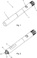
- the injection device 1 When delivered to a user, the injection device 1 has a cap 2 secured to the distal end of the housing 3 as disclosed in figure 1 . Further, the injection device 1 has a dose setting button 4 at its proximal end and a window 5 provided in the housing 3 through which the user can visually inspect the size of the dose being set by rotating the dose setting button 4.
- Figure 2 discloses the injection device 1 with the cap 2 removed. In this mode, the user can inspect the drug contained in the injection device through the inspection opening 6.
- the shield 20 is in its retracted position and the user has full access to the connecting means 31 provided distally on the needle holder 30.
- the injection needle 100 is a conventional pen needle 100 (see figure 12 ) comprising a hub 102 to which a metallic needle cannula 101 is secured.
- the needle cannula 101 has a distal end 103 for penetrating the skin of a user and a proximal end 104 for entering into a cartridge 105 contained in the injection device 1.
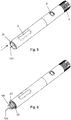
- the shield 20 When a user dials a dose by rotating the dose setting button 4 (indicated by the arrow S in figure 4 ), the shield 20 is automatically moved into its extended position as disclosed in figure 4 . In this extended position the shield 20 visually covers the distal end 103 of the needle cannula 101, at least when the injection device 1 is viewed radially i.e. when vied from the side.
- An injection is hereafter performed simply by pressing the distal end of the shield 20 softly against the skin of the user. This is indicated with the arrow I in figure 5 .
- the distal part 103 of the needle cannula 101 penetrates through the skin of the user, and the shield 20 when moving into its retracted position automatically activates the injection of the set dose as will be explained later.
- the shield 20 is maintained in its retracted position and the needle holder 30 moves axially into its extended position making it possible for the user to exchange the injection needle 100.
- the needle holder 30 is forced forward which decouples the proximal end 104 of the needle cannula 101 from the cartridge 105.
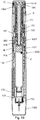
- the mechanics of the injection device 1 is contained in an outer housing 3, which is preferably made from two parts, a distal cartridge holder 3a which is permanently secured to a proximal housing part 3b to form one housing 3.
- An intermediate part 7 carrying a partition 8 is provided between the cartridge holder 3a and the proximal housing part 3b.
- the housing 3 can be formed as one unitary unit.
- the distal end of the housing 3 carries a shield 20 and a needle holder 30 whereas the proximal end of the housing 3 carries the dose setting button 4.
- the distal cartridge holder part 3a further stores the cartridge 105 which is a conventional cartridge 105 having a septum 106 at its distal end and an axially movable plunger 107 slidable provided at its proximal end.
- the plunger 107 By moving the plunger 107 in the distal direction, the volume of the area between the septum 106 and the plunger 107 is reduced with the volume being pressed out through the needle cannula 101 of the injection needle 100.
- the cartridge 105 is axially locked to the housing 3.
- the proximal end 109 of the cartridge 105 abuts the partition 8 as disclosed in figure 10-11 and the shoulders 108 of the cartridge 105 abut inwardly pointing protrusions 9 internally in the housing 3 such that the cartridge 105 cannot slide axially in relation to the housing 3.
- a number of distally pointing fingers 12 can be provided on the partition 8. These fingers 12 preferably has a sloping surface to press against the proximal end 109 of the cartridge 105 as disclosed in figure 11 .
- the inwardly pointing protrusions 9 securing the cartridge 105 distally can be provided at a distal end of the opening 6, they could however be provided wherever needed.
- the cartridge 105 can be moulded to the housing 3.
- a drive mechanism In order to move the plunger 107 forward a drive mechanism is provided which mechanism comprises a threaded piston rod 40 which at its distal end presses against the plunger 107 preferably with a washer 43 provided between the piston rod 40 and the plunger 107.
- the intermediate housing part 7 with its internal partition 8 is inrotatable secured to the housing 3 preferably between the two housing parts 3a, 3b.
- the intermediate housing part 7 could alternatively be moulded as an integral part of the housing 3.
- the outside thread 41 of the piston rod 40 engages an internal thread 10 provided centrally in the intermediate housing part 7 such that whenever the piston rod 40 is rotated it moves axially in relation to the intermediate housing part 7 a distance determined by the number of revolutions of the piston rod 40 and the pitch of the threads 10, 41.
- the piston rod 40 is further provided with an axial stretching track 42 which is engaged by a piston rod guide 50 such that whenever the piston rod guide 50 rotate, the piston rod 40 rotates simultaneously and is screwed forward in the thread connection 10/41.
- the needle holder 30 is as disclosed in figure 12-13 provided with a number of flexible arms 32 which are pressed outwardly by the inherent force of the flexible arms 32. In this outwardly pointing position, the flexible arms 32 abuts the shield 20 in a pair of grooves 21 provided on a flange 22 of the shield 20 such that the shield 20 is prevented from moving distally relatively to the needle mount 30, as indicated in figure 2 . In this position a user can mount the injection needle 100 to the connection means 31. When the injection needle 100 is mounted onto the connecting means 31, the flexible arms 32 will bend and be brought into alignment with the outside surface of the connecting means 31 of the needle holder 30 and the shield 20 can slide freely relatively to the needle mount 30 as depictured in figure 13 .
- a scale drum 60 is provided.
- the scale drum 60 is provided with an external thread 61 engaging a similar thread provided internally in the housing 3 as seen in figure 10 .
- the dose setting button 4 engages the drive tube 70 at its proximal end via a ratchet mechanism which is described in details in the not yet published PCT/EP 2013/055403 to Novo Nordisk A/S.
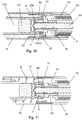
- This ratchet mechanism as disclosed in figure 17 comprises a spring base 80 which is permanently secured to the housing 3 and has an internal toothing engaging the ratchet arms 86 of the ratchet element 85.
- the ratchet element 85 is further provided with an internal toothing 87 engaging a similar toothing 71 externally provided on the drive tube 70 such whenever a user rotates the dose setting button 4 to set a dose, the dose setting button 4 rotates the ratchet element 85 and together with it the drive tube 70.
- the dose setting button 4 engages directly with the ratchet element 85 which rotates together with the dose setting button 4 both when setting a dose and when lowering the set dose by rotating the dose setting button 4 in the opposite direction.
- the dose setting button 4 further has an internally provided protrusion which is able to move the ratchet arm 86 out of engagement with the internal toothing of the spring base 80 when the dose is being lowered.
- a torsion spring A is provided between the drive tube 70 and the spring base 80, which torsion spring A is strained whenever the drive tube 70 is rotated in the dose setting direction.
- the spring base 80 could alternatively be a part of the housing 3 in which case the torsion spring A would be encompassed between the housing 3 and the drive tube 70.
- a helical spring B applying an axial force is provided between a flange 28 on the shield 20 and the internal partition 8 of the intermediate part 7 of the housing 3 urging the shield 20 in the distal direction and a second axially working helical spring C is provided between a flange 33 provided distally on the needle mount 30 and the housing 3 urging the needle mount 30 in the distal direction.
- the helical spring C can rest against the distal side of the internal protrusions 9 inside the housing part 3a securing the cartridge 105 as disclosed in figure 8 .
- the drive tube 70 is on an outside surface provided with an axial groove 72 being engaged by a corresponding raised bar 62 internally in the scale drum 60, such that the scale drum 60 follows rotation of the drive tube 70 and can move axially in relation to the drive tube 70. Since the scale drum 60 is threaded to the housing 3 it performs a helical movement whenever rotated. Externally the scale drum 60 is provided with a series of indicia indicating the size of the dose which indicia can be viewed through the window 5 in the housing 3.
- the distal end the scale drum 60 is internally provided with hooks 63 engaging similar indentations 23 provided proximally on a pair of identical arms 24 a,b provided proximally on the shield 20.
- the shield 20 is urged in the distal direction by the helical spring B which is encompassed between the partition 8 of the intermediate housing part 7 and the shield 20 thus applying a distally orientated force on the shield 20.
- the shield 20 is further provided with an axial surface 25 which is guided by a similar axial surface 11 provided along the inspection opening 6 inside the housing 3 such that the shield 20 is guided solely axially without the possibility of rotating relatively to the housing 3.
- the hooks 63 will engage the indentations 23 on the shield 20 and thus prevent the helical spring B form urging the shield 20 in the distal direction ( figure 10 ), however when the scale drum 60 is rotated to set a dose as disclosed in figure 11 , the indentations 23 are released from the hooks 63 and the shield 20 travels in the distal direction under the force applied by the helical spring B.
- the shield 20 is released to move in the distal direction to cover the distal end 103 of the needle cannula 101.
- An end of content mechanism disclosed in figure 17 comprises an EOC tube 45 and an EOC ring 55.
- the EOC ring 55 carries an outside thread 56 which is threaded inside the EOC tube 45 and is axially guided on the drive tube 70 by having an internal protrusion 57 guided in an axial track 73 on the drive tube 70.
- the EOC tube 45 has an internal flange 49 which is captured by hooks 75 provided on the drive tube 70 allowing the EOC tube 45 to slide a short distance axially in relation to the drive tube 70.
- the drive tube 70 is rotated and the EOC tube 45 is held inrotatable by having teeth 46 engaging similar teeth inside the spring base 80.
- the EOC ring 55 is thereby dialled up the EOC tube 45 a distance which relates to the size of the set dose.
- the drive tube 70 is moved axially in relation to the EOC tube 45 as will be explained later, the result being that the distal toothing 47 on the EOC tube engages a similar toothing in the drive tube 70 such that the drive tube 70 and the EOC tube 45 rotates simultaneously during dosing whereby the EOC ring 55 remains in its relative position.
- the position of the EOC ring 55 in the internal thread of the EOC tube 45 is therefore an expression of the accumulated set doses.
- the helical length of the internal thread of the EOC tube is made such that the EOC ring 55 reaches the end of the internal thread of EOC tube 45 when the cartridge 105 is empty, or at least empty for its usable content. At this point the EOC ring 55 abuts the end of the internal thread and prevents further rotation of the drive tube 70, thus no further dose can be set.
- the EOC tube 45 can further be provided with teeth 48 engaging similar teeth in the spring base 80 providing dose clicks as the EOC tube 45 rotates with the drive tube 70 during dosing.
- the rotation of the dose setting button 4 causes the ratchet element 85 to also rotate. This rotation is transferred to the drive tube 70 via the toothing 71, 87.
- the torsion spring A encompassed between the spring base 80 and the drive tube 70 is strained.
- the torsion thereby being built up in the torsion spring A is held by the ratchet arms 86 engaging the internal toothing of the spring base 80.
- the ratchet arms 86 can be actively released in order to dial down the size of the set dose.
- the scale drum 60 rotate and move helically thus indicating the size of the set dose in the window 5.
- the hooks 63 of the scale drum 60 moves out of the engagement with the indentations 23 of the shield 20 which is then free to move axially under the influence of the helical spring B.
- the shield 20 thus moves to a position covering the distal end 103 of the needle cannula 101 as depictured in figure 4 .
- the injection device 1 is set and ready to perform an injection.
- the shield 20 is pressed against the skin of the user as indicated by the arrow I in figure 5 which will trigger the injection as explained below.
- the needle holder 30 is provided with an identical set of flexible arms 34 a,b. These arms 34 a,b are blocked in the axial direction by an internal flange 13 provided inside the housing 3 as disclosed in figure 14-16 .
- the shield 20 is provided with two identical arms 24 a,b carrying the indentations 23. These arms 24 a, b are each further provided with a protrusion 26 as best seen in figure 16 . As the shield 20 travels in the proximal direction, this protrusion 26 presses the flexible arms 34 a,b inwardly such that the flexible arms 34 a,b, can slide under the internal flange 13 of the housing 3 as in figure 14 and thus allow the needle shield 30 to slide axially.
- the needle holder 30 is further provided with a second pair of identical arms 35 a,b. These arms 35 a,b carries proximally an extension 36.
- the arms 24 a,b of the shield 20 each carry a radial protrusion 27 which peripherally follows the outside surface of the cartridge 105. As the shield 20 is moved axially in the proximal direction, the radial protrusions 27 abuts the extension 36 and further axial movement of the shield 20 will thus force the needle holder 30 to move along with the shield 10 in the proximal direction as the arms 34a,b in this position is able to escape under the flange 13.
- the proximal end 104 of the needle cannula 101 penetrates through the septum 106 of the cartridge 105 since the cartridge 105 which proximally rest against the partition 8 of the intermediate part 7 is prevented from axial movement.
- the set dose is released in the following manner.
- the axial track of the piston rod 40 is engaged by the piston rod guide 50 as disclosed in figure 16 .
- the piston rod guide 50 is further provided with an external toothing 51 (see e.g. figure 11 ) engaging a similar toothing 74 internally in the drive tube 70.
- the drive tube 70 and the piston rod guide 50 can slide axially relatively such they can shift between a position in which the toothing 74 of the drive tube 70 engages with the toothing 51 of the piston rod guide 50 such that the piston rod guide 50 follows the rotation of the drive tube 70 and a position in which the drive tube 70 and the piston rod guide 50 is disengaged.
- the piston rod guide 50 is engaged by the activator 90.
- the activator 90 has a central part 91 which engages the piston rod guide 50 such that the activator 90 can move the piston rod guide 50 axially while the piston rod guide 50 can rotate relatively to the activator 90.
- the activator is provided with two identical legs 92 a,b.
- the proximal end of the arms 34 a,b abuts the arms 92 a,b of the activator 90 and slides the activator 90 in the proximal direction.
- the central part 91 of the activator 90 is provided proximally from this wall partition 8 and the legs 92 a,b, extend through openings in the partition 8.
- the partition 8 is further provided with a toothing 14 ( figure 8 ) which engages a similar toothing 53 internally in the piston rod guide 50 such that the piston rod guide 50 is prevented from rotation relatively to the partition 8 (and the housing 3) as long as the piston rod guide 50 axially abuts the partition 8.
- the scale drum 60 rotates back to its zero position during injection. As the scale drum 60 returns to its zero position as shown in figure 18 , the raised bar 62 engages an axial surface 93 provided externally on the activator 90. The impact of the scale drum 60 with the activator 90 makes the activator 90 rotate an angle. This rotation makes the arms 92 a,b of the activator 90 move under a peripheral extension 36e provided peripheral on the extension 36 which lifts the extension 36 and thereby the proximal end of the arms 35 a,b over the radial protrusion 27.
- both the arms 92 a,b and the extension 36e are preferably provided with an inclined surface as depictured in figure 18 .
- the helical spring C urging an axial force on the needle holder 30 now pushes the needle holder 30 in the distal direction such that the proximal end 104 of the needle cannula 101 is moved out of its engagement with the septum 106 of the cartridge 105.
- the activator 90 is rotated back to its initial position.
- the needle shield 20 is in the zero position locked to the scale drum 60 due to the engagement 63/23 and is thus hindered from moving axially.
- the result being as shown in figure 6 , that the needle shield 20 remains in its retracted position and the needle holder 30 moves into its most distal position thereby making it possible for the user to exchange the injection needle 100
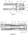
- the housing 1003 is made up from three housing parts; a distal cartridge holder part 1003a holding a cartridge 1105, a proximal housing part 1003b which at its most proximal end is provided with a dose setting button 1004 and an intermediate housing part 1007 connecting the cartridge part 1003a and the proximal housing part 1003b.
- the cartridge holder part 1003a is further, in the non-use situation, covered by a removable cap 1002.
- the intermediate housing part 1007 is further provided with a distal extension 115 which will be explained later and a proximal extension 116.
- the proximal extension 116 has at its most proximal end a pointer which will appear in the scale window 1005 when the housing 1003 is assembled (best seen in figure 21-22 ). Further, the proximal extension 116 can carry an inwardly pointing thread segment 117 for engaging the external thread 161 on the scale drum 160.
- the proximal housing part 1003a is provided with two opposite located openings 1006 (one of which is depictured in figure 20 ) into which two frames 111 are press fitted. One or both of these frames 111 are internally provided with a holding mechanism 1009 for holding the neck part 1108 of the cartridge 1105. The proximal end 1109 of the cartridge 1105 is secured against the partition 1008 of the intermediate part 1007 such that the cartridge 1105 is fixed in the housing 1003.
- Movable relatively to the housing 1003 is the shield 120 which cover the injection needle during injection and the needle holder 130 having connecting means 131 for securing an injection needle to the needle holder 130.
- the needle holder 130 is further provided with a flexible arm 132 preventing proximal movement of the shield 120 relatively to the needle holder 130 when no injection needle is mounted on the needle holder 130.
- a torsion spring A supplies the torque for performing an injection whereas a compression spring B urges the shield 120 in the distal direction and another compression spring C urges the needle holder 130 in the distal direction.
- the torsion spring A is encompassed between the spring base 180 and the drive tube 170.
- the spring base 180 is permanently fixed to the proximal housing part 1003b but could alternatively be moulded as an integral part of the housing 1003.
- the compression spring B is encompassed between a flange (or similar) 128 on the shield 120 and the internal partition 1008 of the intermediate housing part 1007.
- the flange 128 could alternatively be a number of knobs supporting the spring B.
- the compression spring C is made from a suitable polymer and is moulded as an integral part of the needle holder 130 and encompassed between the needle holder 130 and the partition 1008 of the intermediate housing part 1007.
- the partition 1008 can e.g. be provided with a hole 114 for securing the moulded compression spring C.
- the intermediate housing part 1007 further has an internal thread 110 through which the piston rod 140 is screwed forward when rotated.
- a scale drum 160 for showing the size of the set dose is via an outside thread 161 threaded to the proximal housing part 1003b or to the threaded segment 117 of the proximal extension 116 of the intermediate housing part 1007 (or it can be threaded to both as a security measure) such that the scale drum 160 moves helically when rotated.
- the scale drum 160 is provided with a raised bar 162 axially guided in a corresponding axial groove or the like 172 provided externally on the drive tube 170.
- the raised bar 162 and axial groove 172 engagement could of cause be vice versa in respect of the parts.
- the scale drum 160 is further provided with a hook 163 which holds the shield 120 in its retraced position when the scale drum 160 is in its most distal position i.e. when no dose is set.
- the proximally provided dose setting button 1004 is internally rotatable connected to the ratchet element 185 such that rotation of the dose setting button 104 is transformed into rotation of the ratchet element 185.
- the ratchet element 185 is urged in the distal direction by a compression spring D provided between the proximal end of the ratchet element 185 and the dose setting button 1004. This spring D is preferably moulded integrally with the ratchet element 185 as depictured in figure 19 .
- the dose setting button 1004 is further rotatable connected to the housing 1003 such that it can rotate relative to the proximal housing part 1003b but not move axially.
- the ratchet element 185 is further provided with a ratchet arm 186 which engages an internally toothing 181 provided internally in the spring base 180.
- the engagement of the ratchet arm 186 with the internal toothing 181 prevents the ratchet element 185 from counter rotating.
- the dose setting button 1004 is internally provided with a protrusion 1010 ( figure 19 ) which can move the ratchet arm 186 inwardly when the dose setting button 1004 is rotated oppositely to lower the set dose. In this way the ratchet element 185 can rotate step by step in the opposite direction during dial-down of the dose and under influence of the torsion spring A.
- the user When setting a dose, as depictured in figure 21 , the user simply rotates the dose setting button 1004 which in turn rotates the ratchet element 185. Rotation of the ratchet element 185 is transferred to a rotation of the drive tube 170 as the inner toothed surface 174 of the drive tube 170 is in engagement with the outer tooting 187 provided on the ratchet element 185. The rotation of the drive tube 170 strains the torsion spring A. The torque build up in the torsion spring A is held by the engagement of the ratchet arm 186 with the internal toothing 181 of the spring base 180.
- the scale drum 160 rotates together with the drive tube 170 such that the user can view the set dose through the window 105 provided in the proximal housing part 103b.
- the needle holder 130 is further urged forward by the compression spring C such that the back-end of the injection needle is maintained outside the septum 1106 of the cartridge 1105 when not injecting.
- the distal end of the shield 120 is pressed against the skin of the user.
- the front-end 103 of the injection needle 100 penetrates through the skin while the back-end 104 of the injection needle is out of contact with the septum 1106 of the cartridge 1105 as the needle holder 130 is in its distal position.
- the needle holder 130 is prevented from moving proximally by the engagement of the protrusion 134a carried on the flexible arm 134 against an inwardly pointing protrusion 113 (see figure 20 ) provided on the frame 111.
- the shield 120 will force the protrusion 134a out of its engagement with the inwardly pointing protrusions 113 of the frame 111 since the vertical protrusion 134b of the flexible arm 134 is guided in a track 126 in the shield 120.
- the shape of this track 126 moves the protrusion 134a (via 134b) out of its engagement with the inwardly pointing protrusion 113 on the frame 111 where after the shield 120 and the needle holder 130 move axially together.
- the shield 120 and needle holder 130 moves together since the protrusion 136 provided on the arm 135 locks to the hook 127 proximally provided on the shield 120. Axial movement of the shield 120 is thus transferred to the needle holder 130. This is best seen in figure 23-24 which depictures the situation occurring during dose expelling and just before the scale drum 160 reaches its zero position.
- the hook 127 engages the protrusion 136 thus transferring axial movement of the shield 120 to axial movement of the needle holder 130.
- the arm 135 carrying the protrusion 136 is guided into position by the curved wall 129 leading up to the hook 127. Oppositely the arm 135 is supported by the curved extension 115 on the intermediate housing part 1007.
- release arms 137 are provided Proximally on the needled holder 130 . These release arms 137 extent parallel with the flexible arm 135. When the shield 120 and the needle holder 130 is in their proximal position, the release arms 137 moves the clutch 190 as depictured in figure 22 . This brings the external toothing 191 on the clutch 190 into engagement with a similar toothing 174 provided internally in the drive tube 170 such that the drive tube 170 and the clutch 190 rotate together.
- the ratchet element 185 rotates the drive tube 170 via the engagement of the externally provided toothing 187 engaging the toothing 174 internally in the drive tube 170, see figure 21 .
- the ratchet element 185 rotate together with the dose setting button 1004, but during dosing both the dose setting button 1004 and the ratchet element 185 remains non-rotatable.
- the clutch 190 is moved proximally by the arms 137, the ratchet element 185 is also moved proximally against the bias of a proximally moulded spring arm D provided proximally on the ratchet element 185 and resting against an inside surface of the dose setting button 1004.
- This proximal movement of the ratchet element 185 releases the coupling between the toothing 174 of the drive tube 170 and the toothing 187 provided on the ratchet element 185 such that the drive tube 170 is free to rotate under influence of the torque of the torsion spring A.
- the rotation of the drive tube 170 is transferred to a rotation of the clutch 190 by the coupling between the internal toothing 174 on the drive tube 170 and the toothing 191 externally and proximally on the clutch 190.
- a further toothing 171 is also provided internally in drive tube 170, which toothing 171 operates against click arms 188 provided externally on the ratchet element 185 to provide dose clicks during injection i.e. when the drive tube 170 rotate relatively to the ratchet element 185.
- the rotation of the clutch 190 is transferred to a rotation of the piston rod guide 150 as the toothed outer surface 151 of the piston rod guide 150 is in engagement with the internal toothing 194 of the clutch 190 when the clutch 190 is moved proximally during dosing as disclosed in figure 22 .
- this internal toothing 194 of the clutch 190 is in engagement with a toothing 118 on the intermediate housing member 1007 when the injection device is not activated.
- the rotation of the piston rod guide 150 is transferred to a rotation of the piston rod 140 as the piston rod guide 150 engages a longitudinal track in the piston rod 140.
- the pressure relief mechanism is similar to the one disclosed in EP 12-188471 by Novo Nordisk A/S and serves the purpose of allowing axial movement of the rubber plunger 1107 of the cartridge 1105 and thus also of the piston rod 140. Such axial movement of the rubber plunger occurs e.g. as a result of temperature variations.
- the pressure relief mechanism comprises of the clutch 190, the piston rod guide 150, a click element 165 and a leaf spring E.
- the piston rod 140 will be forced proximally by the rubber plunger 1107 inside the cartridge 1105, which will push the piston rod foot 143 and thus the piston rod 140 proximally. This will generate a rotation of the piston rod 140 as the piston rod 140 is threaded to the thread 1008 of the intermediate part 1007.
- the click element 165 is externally provided with a plurality of click fingers 166 which operates in a toothing 195 provided internally in the clutch 190.
- This toothing 195 is adapted to prevent rotation of the click element 165 in one direction and adapted to have reluctance to rotation in the opposite direction (due to the inherent outwardly flexibility of the click fingers 166).
- the direction having the reluctance is the one being used when the piston rod 140 move proximally as the temperature rises.
- the leaf spring E is encompassed between the piston rod guide 150 and the click element 155 such that one leg of the leaf spring D is attached to the piston rod guide 150 and the other leg is attached to the click element 165 thus a torque will be introduced in the leaf spring E when the piston rod guide 150 and the click element 165 rotate relative to each other independently of the direction of this rotation.
- End-of-Content mechanism is a so-called non-axial movable cycloid End-of-Content mechanism which is disclosed in details in EP 13-153628 by Novo Nordisk A/S.
- the End-of-Content mechanism comprises an End-of-Content ring 155 which internally rides on an outside surface of the clutch 190 and externally is connected to a toothed ring 175 provided inside drive tube 170 such that the End-of-Content ring 155 rotate when the drive tube 170 is rotated relatively to the clutch 190.
- the End-of-Content ring 155 Due to the cycloid gearing the End-of-Content ring 155 is rotated a greater angle for each angular rotation of the drive tube 170 thereby counting the rotational movement of the drive tube 170.
- the total allowable angular movement of the End-of-Content ring 155 is predetermined such that the End-of-Content ring 155 encounters a stop just before the injectable content of the cartridge 1105 has been set. Once the End-of-Content ring 155 reaches its stop, the drive tube 170 cannot be rotated further thus no further dose can be set.
- End-of-Content mechanism thereby counting the accumulated set and ejected doses and stopping further dose setting when this accumulated value equals the initial injectable amount of liquid drug in the cartridge 1105.
- the surface 164 on the scale drum 160 encounters the protrusion 136 and pushes it out of its engagement with the hook 127 such that the needle holder 130 can move distally independently of the shield 120.
- the protrusion 136 is hindered by axial movement by the supporting surface 115 until the shield 120 has moved a little distance in the distal direction (the distance is indicated by the arrow Z in figure 23 ).
- the axial movement being the axial distance Z between hook 163 and indentation 123 seen in figure 23 . Only when the shield 120 has moved to the hooked position ( figure 25 ) is the distance to the supporting surface 115 sufficient to allow the protrusion 136 to be fully released where after the needle holder 130 returns to its extended position.
- the hook 163 provided on the scale drum 160 once again engages the indentation 123 provided proximately on the shield 120 thus preventing further axial movement of the shield 120 as depictured in figure 24-25 .
- the shield 120 When setting a dose by rotating the dose setting button 1004, the shield 120 is urged forward by the spring B. However, if the user for some reason regrets this and wants to retract the shield 120 this can be done by counter rotating the dose setting button 1004 until the scale drum160 reaches its zero position and then press the shield 120 in the proximal direction.
- the hook 163 In order for the indentation 123 to pass the hook 163 and obtain an engagement, the hook 163 has to have a certain degree of flexibility in a radial direction (i.e. perpendicular to the axial direction of the scale drum 160) such that the hook 163 can flex outwardly as the indentation 123 passes on the back-side of the hook 163.
- the scale drum 160 is provided with a cut-out 167 (see figure 24 ), which cut-out 167 is located in the proximity of the hook 163.
- Figure 24A discloses the area of the scale drum 160 around the hook 163 seen from the backside.
- the hook 163 is provided with a slanted distal face 168 better allowing the inclined proximal surface of the indentation 123 to pass behind (i.e. on the inward side) the hook 163 in its axial movement.
Landscapes
- Health & Medical Sciences (AREA)
- Engineering & Computer Science (AREA)
- Hematology (AREA)
- Anesthesiology (AREA)
- Biomedical Technology (AREA)
- Heart & Thoracic Surgery (AREA)
- Vascular Medicine (AREA)
- Life Sciences & Earth Sciences (AREA)
- Animal Behavior & Ethology (AREA)
- General Health & Medical Sciences (AREA)
- Public Health (AREA)
- Veterinary Medicine (AREA)
- Environmental & Geological Engineering (AREA)
- Infusion, Injection, And Reservoir Apparatuses (AREA)
Description
- The invention relates to a spring driven injection device for injection of multiple set doses. In particular, the invention relates to a spring driven injection device of the type where the injection needle is shielded during injection and where the axial movement of the needle shield releases the injection of the set dose under influence of the spring which is preferably, but not exclusively, a torsion spring.
- An automatic torsion spring driven injection device is disclosed in
EP 338,806 - A different spring driven pen-shaped injection device having a shielded injection needle is known from
US 7,112,187 . The injection device disclosed is an automatic spring-driven injection in which an actuation spring provided inside the housing thrusts the piston rod forward during injection. An important characteristic of such automatic injection device is that no element move out from the injection device during dose setting. Thus, the injection device has a constant length during operation. This particular injection device has a mode selector which is rotated to select one out of three different modes. In one mode the shield is locked and in a different mode the shield is unlocked. In the unlocked position, the shield can be moved axially between an extended and a retracted position. In the retracted position a user has access to the distal end of the injection device and is thus able to attach or remove an injection needle. Further, the mode selector can be rotated to an injection position, in which position the set dose is released when the shield is moved to its retracted position during injection. For automatic spring driven injection devices for multiple injections of set doses in which the triggering of the injection is made by the backward movement of the needle shield a particular challenge is present. In order to exchange the injection needle, the needle shield needs to be axially removed from the hub of the injection needle such that the user can rotate or twist the hub in order to couple or decouple the injection needle. However, when performing the injection, the needle shield must trigger the release of the dose when only the distal part of the needle cannula is penetrated into the body. - In
EP 338,806 US 7,112,187 it is done by a complicated mechanism involving a mode selector. However, in both examples it is difficult to explain the user how to handle the injection device as the user has to perform many different steps and remember which steps in the sequence of executing the injection he or she has fulfilled. - A further manual injection device in which the cartridge is disconnected from the injection needle by axial movement of the cartridge is described in
WO 2011/051366 . -
US 2006/178630 A1 discloses the features of the preamble ofclaim 1. - It is an object of the present invention to provide a spring driven injection device for multiple automatic injections of set doses which are very simple to handle and which do not require any explanation to the user but wherein the working of the injection device is self-explanatory.
- It is particularly an object of the present invention to provide a shield triggered automatic injection device which facilitates easy exchange of the injection needle without the user unintentionally pushing on the needle shield and thereby activating the injection process.
- It is specifically an object to provide a mechanism which secures and restrains the needle shield in its retracted position.
- The invention is defined the claims.
- Accordingly, in one embodiment which is not part of the present invention, an injection device for a spring driven injection of a liquid drug is provided, which in a first embodiment comprises:
- A housing storing a cartridge containing the liquid drug to be injected.
- A needle interface to which an injection needle is mountable,
- A needle shield for covering the injection needle during use,
- Spring means for urging the needle shield in the distal direction, and
- In this way, the needle shield can only be urged by the spring to slide relatively to the needle interface when an injection needle has been mounted onto the needle holder.
- When no injection needle is mounted, the needle shield is secured in its proximal retracted position thus allowing a user to change the injection needle, and when an injection needle is mounted and the flexible arms are activated i.e. moved to a position allowing the needle shield to pass in its sliding movement towards its distal position.
- The arms, which can be any number including one, are preferably moved into alignment with the needle interface by the hub of the injection needle when mounted onto the needle interface.
- The needle interface is preferably provided with means engaging similar means in the interior of a needle hub. These means can be any known means such as a luer, a thread or a bayonet coupling or any combination thereof.
- The arms are preferably moulded together with the needle interface as flexible polymer arms which has a build-in resiliency and flexes in an outward direction radial to the longitudinal direction of the injection device such that the arms are pressed inwardly by the hub of the injection needle when mounted and flexes to the initial stopping position once the hub of the injection needle is removed after use.
- All though the term "arms" are used throughout the description it is clear that what is meant is any means similar to arms that provides the effect of blocking axial movement of the shield when no injection needle is mounted and which means are radially moved to an aligned position by mounting of the injection needle thus allowing the shield to slide freely. According to the invention, the needle shield is prevented from axial movement by engagement between the needle shield and the scale drum. In this aspect, the spring driven delivery device comprises the features of
claim 1. By locking is meant that the needle shield is prevented from moving in the distal direction under influence of the spring means urging the needle shield distally. - Whenever the scale drum is in its zero position, i.e. the position in which no dose has been set, and the cipher "0" (or a similar indicia) appears in the window or display of the injection device, engagement means on the scale drum arrests the needle shield and secures it from axial movement.
- When a user dials a dose and the scale drum moves away from its zero position, these engagement means releases and set the needle shield free to move axially under influence of the spring whereby the needle shield is slidable into a position in which it covers the injection needle.
- The engagement means are preferably hooks and indentations provided respectfully on the scale drum and on the needle shield.
- During injection the user presses the needle shield towards the skin to activate the injection. Once the scale drum has returned to its initial zero position the injection is over and the user removes the needle shield from the skin.
- The distance between the hook and the indentation are preferably such that they only engage when the shield has moved a distance in the distal direction to make sure that they only hook and lock when the shield is fully removed from the skin of the user.
- When pressing the shield proximally with the scale drum located in its zero position, the indentation on the shield passes on the inside on the hook. To facilitate this, the hook is made flexible in a radial direction by providing a cut-out in the proximity of the hook.
- An "injection pen" is typically an injection apparatus having an oblong or elongated shape somewhat like a pen for writing. Although such pens usually have a tubular cross-section, they could easily have a different cross-section such as triangular, rectangular or square or any variation around these geometries.
- The term "Needle Cannula" is used to describe the actual conduit performing the penetration of the skin during injection. A needle cannula is usually made from a metallic material such as e.g. stainless steel and connected to a hub to form a complete injection needle also often referred to as a "needle assembly" or simply an "injection needle" A needle cannula could however also be made from a polymeric material or a glass material. The hub also carries the connecting means for connecting the needle assembly to an injection apparatus and is usually moulded from a suitable thermoplastic material. The "connection means" could as examples be a luer coupling, a bayonet coupling, a threaded connection or any combination thereof e.g. a combination as described in
EP 1,536,854 . - Needle assemblies specially designed for pen injections systems are defined in ISO standard No. 11608,
part 2, and are often referred to as "pen needles". Pen needles have a front-end for penetrating into the skin of the user and a back-end for penetrating into the cartridge containing the drug. - As used herein, the term "drug" is meant to encompass any drug-containing flowable medicine capable of being passed through a delivery means such as a hollow needle in a controlled manner, such as a liquid, solution, gel or fine suspension. Representative drugs includes pharmaceuticals such as peptides, proteins (e.g. insulin, insulin analogues and C-peptide), and hormones, biologically derived or active agents, hormonal and gene based agents, nutritional formulas and other substances in both solid (dispensed) or liquid form.
- "Scale drum" is meant to be a cylinder shaped element carrying indicia indicating the size of the selected dose to the user of the injection pen. The cylinder shaped element making up the scale drum can be either solid or hollow. "Indicia" is meant to incorporate any kind of printing or otherwise provided symbols e.g. engraved or adhered symbols. These symbols are preferably, but not exclusively, Arabian numbers from "0" to "9". In a traditional injection pen configuration the indicia is viewable through a window provided in the housing. When reference is made to a "zero position" of the scale drum, this does not necessarily mean that the number "0" is present, however it merely refers to the position of the scale drum in which no dose has been set.
- "Cartridge" is the term used to describe the container containing the drug. Cartridges are usually made from glass but could also be moulded from any suitable polymer. A cartridge or ampoule is preferably sealed at one end by a pierceable membrane referred to as the "septum" which can be pierced e.g. by the back-end of an injection needle. The opposite end is typically closed by a plunger or piston made from rubber or a suitable polymer. The plunger or piston can be slidable moved inside the cartridge. The space between the pierceable membrane and the movable plunger holds the drug which is pressed out as the plunger decreased the volume of the space holding the drug. However, any kind of container - rigid or flexible - can be used to contain the drug.
- Since a cartridge usually has a narrower neck portion into which the rubber plunger cannot be moved, not all of the drug contained inside the cartridge can be expelled. The term "initial quantum" therefore refers to the initial quantum of the injectable content. The term "remaining content" in the same way refers to the remaining injectable content.
- Using the term "Automatic" in conjunction with injection device means that, the injection device is able to perform the injection without requiring the user of the injection device to manually deliver the force needed to expel the drug. The force is typically delivered by an electric motor or by a spring as herein described which spring is strained by the user during dose setting. Such springs are usually prestrained in order to avoid problems of delivering very small doses. Alternatively, the spring can be preloaded by the manufacturer with a preload sufficient to empty the drug cartridge though a number of doses. Typically the user activates a latch or a button on the injection device to release the force accumulated in the spring when carrying out the injection.
- All headings and sub-headings are used herein for convenience only and should not be constructed as limiting the invention in any way.
- The use of any and all examples, or exemplary language (e.g. such as) provided herein, is intended merely to better illuminate the invention and does not pose a limitation on the scope of the invention unless otherwise claimed. No language in the specification should be construed as indicating any non-claimed element as essential to the practice of the invention. The citation and incorporation of patent documents herein is done for convenience only and does not reflect any view of the validity, patentability, and/or enforceability of such patent documents.
- This invention includes all modifications and equivalents of the subject matter recited in the claims appended hereto as permitted by applicable law.
- The invention will be explained more fully below in connection with a preferred embodiment and with reference to the drawings in which:
- Figure 1
- show a perspective view of the injection device prior to use.
- Figure 2
- show a perspective view of the injection device with the cap removed.
- Figure 3
- show a perspective view of the injection device with the injection needle mounted.
- Figure 4
- show a perspective view of the injection device with the needle shield in its extended position.
- Figure 5
- show a perspective view of the injection device during injection.
- Figure 6
- show a perspective view of the injection following injection.
- Figure 7.1-7.8
- show a schematic view of the various sequences of performing an injection using the injection device according to the invention.
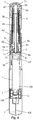
- Figure 8
- show a cross sectional view of the injection device according to a first example.
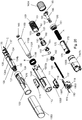
- Figure 9
- show an exploded view of the injection device in
figure 8 . - Figure 10
- show a detailed cross sectional view of the engagement between the needle shield and the scale drum.
- Figure 11
- show a detailed cross sectional view of the needle shield released from the scale drum.
- Figure 12
- show a detailed cross sectional view of the connecting means of the needle holder without an injection needle attached.
- Figure 13
- show a detailed cross sectional view of the connecting means of the needle holder with an injection needle attached.
- Figure 14
- show a detailed cross sectional view of the activation mechanism during injection.
- Figure15
- show a different detailed cross sectional view of the activation mechanism.
- Figure 16
- show a detailed cross sectional view of the activation mechanism upon activation.
- Figure 17
- show a detailed cross sectional view of the proximal end of the injection device.
- Figure 18
- show a perspective view of the mechanism releasing the needle holder following injection.
- Figure 19
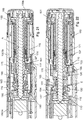
- show a cross sectional view of the injection device according to a second example.
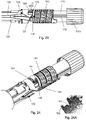
- Figure 20
- show an exploded view of the injection device in
figure 19 . - Figure 21
- show a cross sectional view of the injection mechanism according to the
figures 19-20 in the non-dosing position. - Figure 22
- show a cross sectional view of the injection mechanism according to the
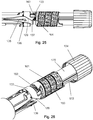
figures 19-20 when releasing a set dose. - Figure 23
- show a side view of the interior of the injection device of the
figures 19-20 with the needle holder locked to the needle shield. - Figure 24
- show a perspective view of
figure 23 . - Figure 24A
- show a perspective view of the inside of scale drum.
- Figure 25
- show a side view of the interior of the injection device of the
figures 19-20 with the needle holder released from the needle shield and the needle shield locked to the scale drum. - Figure 26
- show a perspective view of
figure 25 . - The figures are schematic and simplified for clarity, and they just show details, which are essential to the understanding of the invention, while other details are left out. Throughout, the same reference numerals are used for identical or corresponding parts.
- When in the following terms as "upper" and "lower", "right" and "left", "horizontal" and "vertical", "clockwise" and "counter clockwise" or similar relative expressions are used, these only refer to the appended figures and not to an actual situation of use. The shown figures are schematic representations for which reason the configuration of the different structures as well as there relative dimensions are intended to serve illustrative purposes only.
- In that context it may be convenient to define that the term "distal end" in the appended figures is meant to refer to the end of the injection device which usually carries the injection needle whereas the term "proximal end" is meant to refer to the opposite end pointing away from the injection needle and carrying the dose dial button as depictured in the
figures 1 to 6 . -
Figure 1 to figure 7 discloses a torsion spring driven injection device during its different stages. The features and the working modes disclosed in thefigures 1 to 7 is common for both examples. - When delivered to a user, the
injection device 1 has acap 2 secured to the distal end of thehousing 3 as disclosed infigure 1 . Further, theinjection device 1 has adose setting button 4 at its proximal end and awindow 5 provided in thehousing 3 through which the user can visually inspect the size of the dose being set by rotating thedose setting button 4. -
Figure 2 discloses theinjection device 1 with thecap 2 removed. In this mode, the user can inspect the drug contained in the injection device through theinspection opening 6. Theshield 20 is in its retracted position and the user has full access to the connecting means 31 provided distally on theneedle holder 30. - In this mode the axial movement of the
shield 20 in the distal direction is hindered by twoflexible arms 32 provided on theneedle holder 30 and shown in details onfigure 12-13 . Theseflexible arms 32 are provided in conjunction with the connecting means 31 such that once aninjection needle 100 is connected to the connection means 31, thisinjection needle 100 pushes theflexible arms 32 inwardly to allow passage of the axialmovable shield 20 in the distal direction. - In
figure 3 , the user has attached aninjection needle 100 to the connectingmeans 31. Theinjection needle 100 is a conventional pen needle 100 (seefigure 12 ) comprising ahub 102 to which ametallic needle cannula 101 is secured. Theneedle cannula 101 has adistal end 103 for penetrating the skin of a user and aproximal end 104 for entering into acartridge 105 contained in theinjection device 1. - When a user dials a dose by rotating the dose setting button 4 (indicated by the arrow S in
figure 4 ), theshield 20 is automatically moved into its extended position as disclosed infigure 4 . In this extended position theshield 20 visually covers thedistal end 103 of theneedle cannula 101, at least when theinjection device 1 is viewed radially i.e. when vied from the side. - An injection is hereafter performed simply by pressing the distal end of the
shield 20 softly against the skin of the user. This is indicated with the arrow I infigure 5 . Thedistal part 103 of theneedle cannula 101 penetrates through the skin of the user, and theshield 20 when moving into its retracted position automatically activates the injection of the set dose as will be explained later. - Following injection, when the
distal end 103 of theneedle cannula 101 is removed from the skin of the user as disclosed infigure 6 , theshield 20 is maintained in its retracted position and theneedle holder 30 moves axially into its extended position making it possible for the user to exchange theinjection needle 100. - The various sequences of an injection are schematically disclosed in
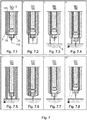
figure 7 . The details will be further explained in the following. - In
figure 7.1 , thecap 2 has been removed and theinjection needle 100 has been connected to the connection means 31 of theneedle holder 30. No dose has been dialled as can be seen in thewindow 5. - In
figure 7.2 the user dials a dose, and theshield 20 is moved forward to cover thedistal end 103 of theinjection needle 101. - In
figure 7.3 theshield 20 is pressed against the skin S of a user. - In
figure 7.4 , thedistal end 103 of theneedle cannula 101 has penetrated through the skin S of the user and theneedle holder 30 and theshield 20 locks to each other and moves axially together as further disclosed infigure 15 . - In
figure 7.5 , theproximal end 104 of theneedle cannula 101 has penetrated through theseptum 106 of thecartridge 105. The injection itself is being executed in this position, indicated by the number "0" appearing in thewindow 5. Once the scale drum in returned to zero it locks the shield to the housing (via the scale drum). - In
figure 7.6 theneedle holder 30 is forced forward which decouples theproximal end 104 of theneedle cannula 101 from thecartridge 105. - In
figure 7.7 this decoupling is fulfilled and infigure 7.8 theneedle holder 30 locks to thehousing 3. - The operation of the
injection device 1 according to a first example will be explained in details in conjunction with thefigures 8 to 18 . - The mechanics of the
injection device 1 is contained in anouter housing 3, which is preferably made from two parts, adistal cartridge holder 3a which is permanently secured to aproximal housing part 3b to form onehousing 3. Anintermediate part 7 carrying apartition 8 is provided between thecartridge holder 3a and theproximal housing part 3b. Alternatively thehousing 3 can be formed as one unitary unit. - As identified before, the distal end of the
housing 3 carries ashield 20 and aneedle holder 30 whereas the proximal end of thehousing 3 carries thedose setting button 4. - The distal
cartridge holder part 3a further stores thecartridge 105 which is aconventional cartridge 105 having aseptum 106 at its distal end and an axiallymovable plunger 107 slidable provided at its proximal end. By moving theplunger 107 in the distal direction, the volume of the area between theseptum 106 and theplunger 107 is reduced with the volume being pressed out through theneedle cannula 101 of theinjection needle 100. - The
cartridge 105 is axially locked to thehousing 3. Theproximal end 109 of thecartridge 105 abuts thepartition 8 as disclosed infigure 10-11 and theshoulders 108 of thecartridge 105 abut inwardly pointingprotrusions 9 internally in thehousing 3 such that thecartridge 105 cannot slide axially in relation to thehousing 3. In order to obtain the tolerances of the cartridge a number of distally pointingfingers 12 can be provided on thepartition 8. Thesefingers 12 preferably has a sloping surface to press against theproximal end 109 of thecartridge 105 as disclosed infigure 11 . The inwardly pointingprotrusions 9 securing thecartridge 105 distally can be provided at a distal end of theopening 6, they could however be provided wherever needed. Alternatively thecartridge 105 can be moulded to thehousing 3. - In order to move the
plunger 107 forward a drive mechanism is provided which mechanism comprises a threadedpiston rod 40 which at its distal end presses against theplunger 107 preferably with awasher 43 provided between thepiston rod 40 and theplunger 107. - The
intermediate housing part 7 with itsinternal partition 8 is inrotatable secured to thehousing 3 preferably between the twohousing parts intermediate housing part 7 could alternatively be moulded as an integral part of thehousing 3. Theoutside thread 41 of thepiston rod 40 engages aninternal thread 10 provided centrally in theintermediate housing part 7 such that whenever thepiston rod 40 is rotated it moves axially in relation to the intermediate housing part 7 a distance determined by the number of revolutions of thepiston rod 40 and the pitch of thethreads - The
piston rod 40 is further provided with anaxial stretching track 42 which is engaged by apiston rod guide 50 such that whenever thepiston rod guide 50 rotate, thepiston rod 40 rotates simultaneously and is screwed forward in thethread connection 10/41. - The
needle holder 30 is as disclosed infigure 12-13 provided with a number offlexible arms 32 which are pressed outwardly by the inherent force of theflexible arms 32. In this outwardly pointing position, theflexible arms 32 abuts theshield 20 in a pair ofgrooves 21 provided on aflange 22 of theshield 20 such that theshield 20 is prevented from moving distally relatively to theneedle mount 30, as indicated infigure 2 . In this position a user can mount theinjection needle 100 to the connection means 31. When theinjection needle 100 is mounted onto the connectingmeans 31, theflexible arms 32 will bend and be brought into alignment with the outside surface of the connecting means 31 of theneedle holder 30 and theshield 20 can slide freely relatively to theneedle mount 30 as depictured infigure 13 . - In order to visually indicate the size of the dose being set by rotating the dose setting button 4 a
scale drum 60 is provided. Thescale drum 60 is provided with anexternal thread 61 engaging a similar thread provided internally in thehousing 3 as seen infigure 10 . - The
dose setting button 4 engages thedrive tube 70 at its proximal end via a ratchet mechanism which is described in details in the not yet publishedPCT/EP 2013/055403 figure 17 comprises aspring base 80 which is permanently secured to thehousing 3 and has an internal toothing engaging theratchet arms 86 of theratchet element 85. - The
ratchet element 85 is further provided with aninternal toothing 87 engaging asimilar toothing 71 externally provided on thedrive tube 70 such whenever a user rotates thedose setting button 4 to set a dose, thedose setting button 4 rotates theratchet element 85 and together with it thedrive tube 70. - The
dose setting button 4 engages directly with theratchet element 85 which rotates together with thedose setting button 4 both when setting a dose and when lowering the set dose by rotating thedose setting button 4 in the opposite direction. Thedose setting button 4 further has an internally provided protrusion which is able to move theratchet arm 86 out of engagement with the internal toothing of thespring base 80 when the dose is being lowered. - A torsion spring A is provided between the
drive tube 70 and thespring base 80, which torsion spring A is strained whenever thedrive tube 70 is rotated in the dose setting direction. Thespring base 80 could alternatively be a part of thehousing 3 in which case the torsion spring A would be encompassed between thehousing 3 and thedrive tube 70. - Besides the torsion spring A delivering the torsional force to perform the injection, two other springs are provided. A helical spring B applying an axial force is provided between a
flange 28 on theshield 20 and theinternal partition 8 of theintermediate part 7 of thehousing 3 urging theshield 20 in the distal direction and a second axially working helical spring C is provided between aflange 33 provided distally on theneedle mount 30 and thehousing 3 urging theneedle mount 30 in the distal direction. The helical spring C can rest against the distal side of theinternal protrusions 9 inside thehousing part 3a securing thecartridge 105 as disclosed infigure 8 . - The
drive tube 70 is on an outside surface provided with anaxial groove 72 being engaged by a corresponding raisedbar 62 internally in thescale drum 60, such that thescale drum 60 follows rotation of thedrive tube 70 and can move axially in relation to thedrive tube 70. Since thescale drum 60 is threaded to thehousing 3 it performs a helical movement whenever rotated. Externally thescale drum 60 is provided with a series of indicia indicating the size of the dose which indicia can be viewed through thewindow 5 in thehousing 3. - As disclosed in
figures 10-11 , the distal end thescale drum 60 is internally provided withhooks 63 engagingsimilar indentations 23 provided proximally on a pair ofidentical arms 24 a,b provided proximally on theshield 20. - The
shield 20 is urged in the distal direction by the helical spring B which is encompassed between thepartition 8 of theintermediate housing part 7 and theshield 20 thus applying a distally orientated force on theshield 20. Theshield 20 is further provided with anaxial surface 25 which is guided by a similaraxial surface 11 provided along theinspection opening 6 inside thehousing 3 such that theshield 20 is guided solely axially without the possibility of rotating relatively to thehousing 3. - Whenever the
scale drum 60 is in its most distal position, thehooks 63 will engage theindentations 23 on theshield 20 and thus prevent the helical spring B form urging theshield 20 in the distal direction (figure 10 ), however when thescale drum 60 is rotated to set a dose as disclosed infigure 11 , theindentations 23 are released from thehooks 63 and theshield 20 travels in the distal direction under the force applied by the helical spring B. Thus, when a user dials a dose as depictured infigure 4 (arrow D), theshield 20 is released to move in the distal direction to cover thedistal end 103 of theneedle cannula 101. - An end of content mechanism disclosed in
figure 17 comprises anEOC tube 45 and anEOC ring 55. TheEOC ring 55 carries anoutside thread 56 which is threaded inside theEOC tube 45 and is axially guided on thedrive tube 70 by having aninternal protrusion 57 guided in anaxial track 73 on thedrive tube 70. - Further the
EOC tube 45 has aninternal flange 49 which is captured byhooks 75 provided on thedrive tube 70 allowing theEOC tube 45 to slide a short distance axially in relation to thedrive tube 70. - Whenever a dose is set, the
drive tube 70 is rotated and theEOC tube 45 is held inrotatable by havingteeth 46 engaging similar teeth inside thespring base 80. TheEOC ring 55 is thereby dialled up the EOC tube 45 a distance which relates to the size of the set dose. During expelling of the dose, thedrive tube 70 is moved axially in relation to theEOC tube 45 as will be explained later, the result being that thedistal toothing 47 on the EOC tube engages a similar toothing in thedrive tube 70 such that thedrive tube 70 and theEOC tube 45 rotates simultaneously during dosing whereby theEOC ring 55 remains in its relative position. The position of theEOC ring 55 in the internal thread of theEOC tube 45 is therefore an expression of the accumulated set doses. - The helical length of the internal thread of the EOC tube is made such that the
EOC ring 55 reaches the end of the internal thread ofEOC tube 45 when thecartridge 105 is empty, or at least empty for its usable content. At this point theEOC ring 55 abuts the end of the internal thread and prevents further rotation of thedrive tube 70, thus no further dose can be set. - The
EOC tube 45 can further be provided withteeth 48 engaging similar teeth in thespring base 80 providing dose clicks as theEOC tube 45 rotates with thedrive tube 70 during dosing. - When a user sets a dose by rotating the
dose dial button 4 as indicated infigure 4 , the rotation of thedose setting button 4 causes theratchet element 85 to also rotate. This rotation is transferred to thedrive tube 70 via thetoothing - As the
drive tube 70 is rotated the torsion spring A encompassed between thespring base 80 and thedrive tube 70 is strained. The torsion thereby being built up in the torsion spring A is held by theratchet arms 86 engaging the internal toothing of thespring base 80. Theratchet arms 86 can be actively released in order to dial down the size of the set dose. - As the
drive tube 70 is rotated, thescale drum 60 rotate and move helically thus indicating the size of the set dose in thewindow 5. - As the
scale drum 60 starts to rotate, thehooks 63 of thescale drum 60 moves out of the engagement with theindentations 23 of theshield 20 which is then free to move axially under the influence of the helical spring B. Theshield 20 thus moves to a position covering thedistal end 103 of theneedle cannula 101 as depictured infigure 4 . - Once the user has set the size of the dose to be injected, the
injection device 1 is set and ready to perform an injection. - In order to release the torque applied to the torsion spring A and thereby to perform an injection, the
shield 20 is pressed against the skin of the user as indicated by the arrow I infigure 5 which will trigger the injection as explained below. - The
needle holder 30 is provided with an identical set offlexible arms 34 a,b. Thesearms 34 a,b are blocked in the axial direction by aninternal flange 13 provided inside thehousing 3 as disclosed infigure 14-16 . - Further, the
shield 20 is provided with twoidentical arms 24 a,b carrying theindentations 23. Thesearms 24 a, b are each further provided with aprotrusion 26 as best seen infigure 16 . As theshield 20 travels in the proximal direction, thisprotrusion 26 presses theflexible arms 34 a,b inwardly such that theflexible arms 34 a,b, can slide under theinternal flange 13 of thehousing 3 as infigure 14 and thus allow theneedle shield 30 to slide axially. - The
needle holder 30 is further provided with a second pair ofidentical arms 35 a,b. Thesearms 35 a,b carries proximally anextension 36. - The
arms 24 a,b of theshield 20 each carry aradial protrusion 27 which peripherally follows the outside surface of thecartridge 105. As theshield 20 is moved axially in the proximal direction, theradial protrusions 27 abuts theextension 36 and further axial movement of theshield 20 will thus force theneedle holder 30 to move along with theshield 10 in the proximal direction as thearms 34a,b in this position is able to escape under theflange 13. - As both the
shield 20 and theneedle holder 30 slides in the proximal direction, theproximal end 104 of theneedle cannula 101 penetrates through theseptum 106 of thecartridge 105 since thecartridge 105 which proximally rest against thepartition 8 of theintermediate part 7 is prevented from axial movement. - Once the
proximal end 104 of theneedle cannula 101 has penetrated through theseptum 106 of thecartridge 105 and thedistal end 102 has penetrated through the skin of the user, the set dose is released in the following manner. - The axial track of the
piston rod 40 is engaged by thepiston rod guide 50 as disclosed infigure 16 . Thepiston rod guide 50 is further provided with an external toothing 51 (see e.g.figure 11 ) engaging asimilar toothing 74 internally in thedrive tube 70. Thedrive tube 70 and thepiston rod guide 50 can slide axially relatively such they can shift between a position in which thetoothing 74 of thedrive tube 70 engages with thetoothing 51 of thepiston rod guide 50 such that thepiston rod guide 50 follows the rotation of thedrive tube 70 and a position in which thedrive tube 70 and thepiston rod guide 50 is disengaged. - Distally, the
piston rod guide 50 is engaged by theactivator 90. - The
activator 90 has acentral part 91 which engages thepiston rod guide 50 such that theactivator 90 can move thepiston rod guide 50 axially while thepiston rod guide 50 can rotate relatively to theactivator 90. Distally, the activator is provided with twoidentical legs 92 a,b. - During activation as the
needle holder 30 is moved in the proximal direction by theshield 20, the proximal end of thearms 34 a,b abuts thearms 92 a,b of theactivator 90 and slides theactivator 90 in the proximal direction. - This axial movement of the
activator 90 pushes thepiston rod guide 50 into engagement with thedrive tube 70. - The
central part 91 of theactivator 90 is provided proximally from thiswall partition 8 and thelegs 92 a,b, extend through openings in thepartition 8. Thepartition 8 is further provided with a toothing 14 (figure 8 ) which engages asimilar toothing 53 internally in thepiston rod guide 50 such that thepiston rod guide 50 is prevented from rotation relatively to the partition 8 (and the housing 3) as long as thepiston rod guide 50 axially abuts thepartition 8. - As the
arms 34 a,b axially moves thepiston rod guide 50 out of engagement with thetoothing 14 of thepartition 8 and into engagement with thedrive tube 70 it also moves thedrive tube 70 slightly in the proximal direction. This axial movement of thedrive tube 70 moves theproximal toothing 71 of thedrive tube 70 out of its engagement with theinternal toothing 87 of theratchet 85 as shown infigure 17 . As theratchet element 85 prevents the torque of the torsion spring A from being released, the torsion spring A is now able to rotate thedrive tube 70 which rotates with it thepiston rod guide 50 and thereby thepiston rod 40 to perform an ejection of the liquid drug. - Due to the engagement between the
axial groove 72 of thedrive tube 70 and the raisedbar 62 of thescale drum 60, thescale drum 60 rotates back to its zero position during injection. As thescale drum 60 returns to its zero position as shown infigure 18 , the raisedbar 62 engages anaxial surface 93 provided externally on theactivator 90. The impact of thescale drum 60 with theactivator 90 makes the activator 90 rotate an angle. This rotation makes thearms 92 a,b of theactivator 90 move under aperipheral extension 36e provided peripheral on theextension 36 which lifts theextension 36 and thereby the proximal end of thearms 35 a,b over theradial protrusion 27. In order to enhance this lifting, both thearms 92 a,b and theextension 36e are preferably provided with an inclined surface as depictured infigure 18 . The helical spring C urging an axial force on theneedle holder 30 now pushes theneedle holder 30 in the distal direction such that theproximal end 104 of theneedle cannula 101 is moved out of its engagement with theseptum 106 of thecartridge 105. When setting a dose theactivator 90 is rotated back to its initial position. - The
needle shield 20 is in the zero position locked to thescale drum 60 due to theengagement 63/23 and is thus hindered from moving axially. The result being as shown infigure 6 , that theneedle shield 20 remains in its retracted position and theneedle holder 30 moves into its most distal position thereby making it possible for the user to exchange theinjection needle 100 - A second example which essentially works the same way as the first example is disclosed in the
figures 19 - 26 . - Whenever possible the individual elements of the second example are numbered with the same number as in the first example, however, having the number "1" or "10" in front. The same apply for elements performing the same or similar activity.
- As in
figure 9 the second example is disclosed in an exploded view infigure 20 . - As disclosed the
housing 1003 is made up from three housing parts; a distalcartridge holder part 1003a holding acartridge 1105, aproximal housing part 1003b which at its most proximal end is provided with adose setting button 1004 and anintermediate housing part 1007 connecting thecartridge part 1003a and theproximal housing part 1003b. Thecartridge holder part 1003a is further, in the non-use situation, covered by aremovable cap 1002. - The
intermediate housing part 1007 is further provided with adistal extension 115 which will be explained later and aproximal extension 116. Theproximal extension 116 has at its most proximal end a pointer which will appear in thescale window 1005 when thehousing 1003 is assembled (best seen infigure 21-22 ). Further, theproximal extension 116 can carry an inwardly pointingthread segment 117 for engaging theexternal thread 161 on thescale drum 160. - The
proximal housing part 1003a is provided with two opposite located openings 1006 (one of which is depictured infigure 20 ) into which twoframes 111 are press fitted. One or both of theseframes 111 are internally provided with aholding mechanism 1009 for holding theneck part 1108 of thecartridge 1105. Theproximal end 1109 of thecartridge 1105 is secured against thepartition 1008 of theintermediate part 1007 such that thecartridge 1105 is fixed in thehousing 1003. - Movable relatively to the
housing 1003 is theshield 120 which cover the injection needle during injection and theneedle holder 130 having connectingmeans 131 for securing an injection needle to theneedle holder 130. Theneedle holder 130 is further provided with aflexible arm 132 preventing proximal movement of theshield 120 relatively to theneedle holder 130 when no injection needle is mounted on theneedle holder 130. - Further, a torsion spring A supplies the torque for performing an injection whereas a compression spring B urges the
shield 120 in the distal direction and another compression spring C urges theneedle holder 130 in the distal direction. - The torsion spring A is encompassed between the
spring base 180 and thedrive tube 170. Thespring base 180 is permanently fixed to theproximal housing part 1003b but could alternatively be moulded as an integral part of thehousing 1003. - The compression spring B is encompassed between a flange (or similar) 128 on the
shield 120 and theinternal partition 1008 of theintermediate housing part 1007. Theflange 128 could alternatively be a number of knobs supporting the spring B. - The compression spring C is made from a suitable polymer and is moulded as an integral part of the
needle holder 130 and encompassed between theneedle holder 130 and thepartition 1008 of theintermediate housing part 1007. Thepartition 1008 can e.g. be provided with ahole 114 for securing the moulded compression spring C. - The
intermediate housing part 1007 further has aninternal thread 110 through which thepiston rod 140 is screwed forward when rotated. - A
scale drum 160 for showing the size of the set dose is via anoutside thread 161 threaded to theproximal housing part 1003b or to the threadedsegment 117 of theproximal extension 116 of the intermediate housing part 1007 (or it can be threaded to both as a security measure) such that thescale drum 160 moves helically when rotated. Internally thescale drum 160 is provided with a raisedbar 162 axially guided in a corresponding axial groove or the like 172 provided externally on thedrive tube 170. The raisedbar 162 andaxial groove 172 engagement could of cause be vice versa in respect of the parts. - The
scale drum 160 is further provided with ahook 163 which holds theshield 120 in its retraced position when thescale drum 160 is in its most distal position i.e. when no dose is set. - The proximally provided
dose setting button 1004 is internally rotatable connected to theratchet element 185 such that rotation of thedose setting button 104 is transformed into rotation of theratchet element 185. Theratchet element 185 is urged in the distal direction by a compression spring D provided between the proximal end of theratchet element 185 and thedose setting button 1004. This spring D is preferably moulded integrally with theratchet element 185 as depictured infigure 19 . Thedose setting button 1004 is further rotatable connected to thehousing 1003 such that it can rotate relative to theproximal housing part 1003b but not move axially. - The
ratchet element 185 is further provided with aratchet arm 186 which engages an internallytoothing 181 provided internally in thespring base 180. The engagement of theratchet arm 186 with theinternal toothing 181 prevents theratchet element 185 from counter rotating. However, thedose setting button 1004 is internally provided with a protrusion 1010 (figure 19 ) which can move theratchet arm 186 inwardly when thedose setting button 1004 is rotated oppositely to lower the set dose. In this way theratchet element 185 can rotate step by step in the opposite direction during dial-down of the dose and under influence of the torsion spring A. - When setting a dose, as depictured in
figure 21 , the user simply rotates thedose setting button 1004 which in turn rotates theratchet element 185. Rotation of theratchet element 185 is transferred to a rotation of thedrive tube 170 as the innertoothed surface 174 of thedrive tube 170 is in engagement with the outer tooting 187 provided on theratchet element 185. The rotation of thedrive tube 170 strains the torsion spring A. The torque build up in the torsion spring A is held by the engagement of theratchet arm 186 with theinternal toothing 181 of thespring base 180. - The
scale drum 160 rotates together with thedrive tube 170 such that the user can view the set dose through thewindow 105 provided in the proximal housing part 103b. - Once the
scale drum 160 is rotated away from its "zero" position thehook 163 is rotated out of its engagement with the indentation 123 (seefigure 23-26 ) provided on theshield 120 which is then urged distally by the compression spring B. - The
needle holder 130 is further urged forward by the compression spring C such that the back-end of the injection needle is maintained outside theseptum 1106 of thecartridge 1105 when not injecting. - In order to inject the set dose, the distal end of the
shield 120 is pressed against the skin of the user. - When the user starts to press the
shield 120 against the skin, the front-end 103 of theinjection needle 100 penetrates through the skin while the back-end 104 of the injection needle is out of contact with theseptum 1106 of thecartridge 1105 as theneedle holder 130 is in its distal position. In this position, theneedle holder 130 is prevented from moving proximally by the engagement of theprotrusion 134a carried on theflexible arm 134 against an inwardly pointing protrusion 113 (seefigure 20 ) provided on theframe 111. - However, once the front-
end 103 of theinjection needle 100 is fully inserted into the skin as depictured infigure 7.4 , theshield 120 will force theprotrusion 134a out of its engagement with the inwardly pointingprotrusions 113 of theframe 111 since thevertical protrusion 134b of theflexible arm 134 is guided in atrack 126 in theshield 120. The shape of thistrack 126 moves theprotrusion 134a (via 134b) out of its engagement with the inwardly pointingprotrusion 113 on theframe 111 where after theshield 120 and theneedle holder 130 move axially together. - The
shield 120 andneedle holder 130 moves together since theprotrusion 136 provided on thearm 135 locks to thehook 127 proximally provided on theshield 120. Axial movement of theshield 120 is thus transferred to theneedle holder 130. This is best seen infigure 23-24 which depictures the situation occurring during dose expelling and just before thescale drum 160 reaches its zero position. Thehook 127 engages theprotrusion 136 thus transferring axial movement of theshield 120 to axial movement of theneedle holder 130. - The
arm 135 carrying theprotrusion 136 is guided into position by thecurved wall 129 leading up to thehook 127. Oppositely thearm 135 is supported by thecurved extension 115 on theintermediate housing part 1007. - When the
shield 120 is fully retracted, as depictured infigure 7.5 , the back-end 104 of theinjection needle 100 has penetrated through theseptum 1106 and into thecartridge 1105 and the release of the dose will be activated. - Proximally on the needled
holder 130 one ormore release arms 137 are provided. These releasearms 137 extent parallel with theflexible arm 135. When theshield 120 and theneedle holder 130 is in their proximal position, therelease arms 137 moves the clutch 190 as depictured infigure 22 . This brings theexternal toothing 191 on the clutch 190 into engagement with asimilar toothing 174 provided internally in thedrive tube 170 such that thedrive tube 170 and the clutch 190 rotate together. - During dose setting, the
ratchet element 185 rotates thedrive tube 170 via the engagement of the externally providedtoothing 187 engaging thetoothing 174 internally in thedrive tube 170, seefigure 21 . - Further, during dose setting, the
ratchet element 185 rotate together with thedose setting button 1004, but during dosing both thedose setting button 1004 and theratchet element 185 remains non-rotatable. When the clutch 190 is moved proximally by thearms 137, theratchet element 185 is also moved proximally against the bias of a proximally moulded spring arm D provided proximally on theratchet element 185 and resting against an inside surface of thedose setting button 1004. - This proximal movement of the
ratchet element 185 releases the coupling between thetoothing 174 of thedrive tube 170 and thetoothing 187 provided on theratchet element 185 such that thedrive tube 170 is free to rotate under influence of the torque of the torsion spring A. - The rotation of the
drive tube 170 is transferred to a rotation of the clutch 190 by the coupling between theinternal toothing 174 on thedrive tube 170 and thetoothing 191 externally and proximally on the clutch 190. - I.e. when the clutch 190 slides proximally (moves from the position in
figure 21 to the position offigure 22 ) thetoothing 174 of thedrive tube 170 releases the engagement with thetoothing 187 of theratchet element 185 and couples to thetoothing 191 of the clutch 190. - A
further toothing 171 is also provided internally indrive tube 170, whichtoothing 171 operates against clickarms 188 provided externally on theratchet element 185 to provide dose clicks during injection i.e. when thedrive tube 170 rotate relatively to theratchet element 185. - Please note that in the
figures 21-22 part of the clutch 190 is not visible due to the cross sectional view. However, the clutch 190 is fully depictured infigure 19 - Further, the rotation of the clutch 190 is transferred to a rotation of the
piston rod guide 150 as the toothedouter surface 151 of thepiston rod guide 150 is in engagement with theinternal toothing 194 of the clutch 190 when the clutch 190 is moved proximally during dosing as disclosed infigure 22 . - As seen in
figure 21-22 thisinternal toothing 194 of the clutch 190 is in engagement with atoothing 118 on theintermediate housing member 1007 when the injection device is not activated. - The rotation of the
piston rod guide 150 is transferred to a rotation of thepiston rod 140 as thepiston rod guide 150 engages a longitudinal track in thepiston rod 140. - The pressure relief mechanism is similar to the one disclosed in
EP 12-188471 rubber plunger 1107 of thecartridge 1105 and thus also of thepiston rod 140. Such axial movement of the rubber plunger occurs e.g. as a result of temperature variations. - The pressure relief mechanism comprises of the clutch 190, the
piston rod guide 150, aclick element 165 and a leaf spring E. - If the liquid drug inside the
cartridge 1105 expands due to increasing temperatures, thepiston rod 140 will be forced proximally by therubber plunger 1107 inside thecartridge 1105, which will push thepiston rod foot 143 and thus thepiston rod 140 proximally. This will generate a rotation of thepiston rod 140 as thepiston rod 140 is threaded to thethread 1008 of theintermediate part 1007. - This will force the
piston rod guide 150 to rotate as thepiston rod guide 150 is keyed to thepiston rod 140. - The
click element 165 is externally provided with a plurality ofclick fingers 166 which operates in atoothing 195 provided internally in the clutch 190. Thistoothing 195 is adapted to prevent rotation of theclick element 165 in one direction and adapted to have reluctance to rotation in the opposite direction (due to the inherent outwardly flexibility of the click fingers 166). - The direction having the reluctance is the one being used when the
piston rod 140 move proximally as the temperature rises. - The leaf spring E is encompassed between the
piston rod guide 150 and theclick element 155 such that one leg of the leaf spring D is attached to thepiston rod guide 150 and the other leg is attached to theclick element 165 thus a torque will be introduced in the leaf spring E when thepiston rod guide 150 and theclick element 165 rotate relative to each other independently of the direction of this rotation. - When the
piston rod 140 move proximately and thepiston rod guide 150 rotates, the leaf spring E is tighten until the rotational reluctance of theclick element 165 is overcome where after theclick fingers 166 will move to the subsequent teeth of thetoothing 195. The result being that thepiston rod guide 150 can perform an unlimited rotation in the expanding direction. - When the temperature decreases and the rubber plunger move distally the torque introduced in the leaf spring E will rotate the
piston rod guide 150 since thetoothing 195 prevents theclick element 165 from rotation in this opposite direction. The result being that thepiston rod 140 is rotated forward. - The End-of-Content mechanism is a so-called non-axial movable cycloid End-of-Content mechanism which is disclosed in details in
EP 13-153628 - The End-of-Content mechanism comprises an End-of-
Content ring 155 which internally rides on an outside surface of the clutch 190 and externally is connected to atoothed ring 175 provided insidedrive tube 170 such that the End-of-Content ring 155 rotate when thedrive tube 170 is rotated relatively to the clutch 190. - During dose setting the
drive tube 170 is rotated and the clutch 190 is static thus the End-on-Content ring 155 is rotated. During dosing thedrive tube 170 and the clutch 190 rotate together thus maintaining the End-of-Content ring 155 in the same relative position. - Due to the cycloid gearing the End-of-
Content ring 155 is rotated a greater angle for each angular rotation of thedrive tube 170 thereby counting the rotational movement of thedrive tube 170. The total allowable angular movement of the End-of-Content ring 155 is predetermined such that the End-of-Content ring 155 encounters a stop just before the injectable content of thecartridge 1105 has been set. Once the End-of-Content ring 155 reaches its stop, thedrive tube 170 cannot be rotated further thus no further dose can be set. - The End-of-Content mechanism thereby counting the accumulated set and ejected doses and stopping further dose setting when this accumulated value equals the initial injectable amount of liquid drug in the
cartridge 1105. - Following dose release the user removes the
shield 120 from the skin as disclosed infigure 7.8 . - This makes the
needle holder 130 move distally under the influence of the compression spring C as depictured infigure 23-24 such that the back-end 104 of the attached pen-needle 100 is pulled out of theseptum 1106 of thecartridge 1105. - As the
scale drum 160 approaches its zero position as depictured infigure 23-24 , thesurface 164 on thescale drum 160 encounters theprotrusion 136 and pushes it out of its engagement with thehook 127 such that theneedle holder 130 can move distally independently of theshield 120. - To make sure that the
needle holder 130 do not return until theshield 120 has been fully removed from the skin of the user, theprotrusion 136 is hindered by axial movement by the supportingsurface 115 until theshield 120 has moved a little distance in the distal direction (the distance is indicated by the arrow Z infigure 23 ). The axial movement being the axial distance Z betweenhook 163 andindentation 123 seen infigure 23 . Only when theshield 120 has moved to the hooked position (figure 25 ) is the distance to the supportingsurface 115 sufficient to allow theprotrusion 136 to be fully released where after theneedle holder 130 returns to its extended position. - Also following injection, the
hook 163 provided on thescale drum 160 once again engages theindentation 123 provided proximately on theshield 120 thus preventing further axial movement of theshield 120 as depictured infigure 24-25 . - This mechanism is further disclosed in European patent application No.:
EP 13-170422 - When setting a dose by rotating the
dose setting button 1004, theshield 120 is urged forward by the spring B. However, if the user for some reason regrets this and wants to retract theshield 120 this can be done by counter rotating thedose setting button 1004 until the scale drum160 reaches its zero position and then press theshield 120 in the proximal direction. - The axial movement of the
shield 120 with thescale drum 160 in its zero position however results in the proximal side surface of theindentation 123 striking against the distal side surface of thehook 163 of thescale drum 160. Visually this would be as infigure 25 , however with theindentation 123 being on the left side of thehook 163. - In order for the
indentation 123 to pass thehook 163 and obtain an engagement, thehook 163 has to have a certain degree of flexibility in a radial direction (i.e. perpendicular to the axial direction of the scale drum 160) such that thehook 163 can flex outwardly as theindentation 123 passes on the back-side of thehook 163. - In order to obtain such flexibility, the
scale drum 160 is provided with a cut-out 167 (seefigure 24 ), which cut-out 167 is located in the proximity of thehook 163. -
Figure 24A discloses the area of thescale drum 160 around thehook 163 seen from the backside. Thehook 163 is provided with a slanteddistal face 168 better allowing the inclined proximal surface of theindentation 123 to pass behind (i.e. on the inward side) thehook 163 in its axial movement. - Some preferred embodiments have been shown in the foregoing, but it should be stressed that the invention is not limited to these, but may be embodied in other ways within the subject matter defined in the following claims.
Claims (4)
- A spring driven drug delivery device for delivering set doses of a liquid drug comprising:a housing (3;1003) fixating a cartridge (105;1105) containing the liquid drug to be injected,a rotatable dose setting button at a proximal end for dialing the size of the dose,a scale drum (60;160) rotatably (61;161) engaged with the housing (3;1003); a needle shield (20;120) for covering an injection needle (100) during use, which needle shield (20;120) under influence of spring means (B) is axially slidable in relation to the housing (3), andwherein the scale drum (60;160) is provided with engaging means which engages and locks the needle shield (20; 120) from axial movement when in the zero position,characterised in that- the scale drum (60, 160) is threadely engaged with the housing (3; 1003) to perform a helical movement away from a zero position during setting of a dose;- a window (5) is provided in the housing (3; 1003) through which a user can visually inspect the size of the dose being set by rotating the dose setting button and in which window the cipher "0" or similar indicia appears whenever the scale drum is in its zero position; and wherein when a dose is dialed the scale drum moves away from its zero position whereby the engagement means releases and set the needle shield free to move axially under influence of the spring (B) whereby the needle shield is slidable into a position in which the needle shield covers the injection needle (100).
- A spring driven drug delivery device according to claim 1, wherein the scale drum (60;160) is provided with at least one hook (63;163) engaging a similar indentation (23;123) provided proximally at the needle shield (20;120).
- A spring driven drug delivery device according to claim 2, wherein the hook (63;163) engages the indentation (23;123) once the scale drum (60;160) has returned to its zero position and the shield (20;120) has been released.
- A spring driven drug delivery device according to claim 2 or 3, wherein the scale drum is provided with a cut-out (167).
Priority Applications (1)
| Application Number | Priority Date | Filing Date | Title |
|---|---|---|---|
| EP13731143.7A EP2866857B1 (en) | 2012-06-29 | 2013-06-25 | Spring driven injection device |
Applications Claiming Priority (4)
| Application Number | Priority Date | Filing Date | Title |
|---|---|---|---|
| EP12174289 | 2012-06-29 | ||
| US201261667069P | 2012-07-02 | 2012-07-02 | |
| EP13731143.7A EP2866857B1 (en) | 2012-06-29 | 2013-06-25 | Spring driven injection device |
| PCT/EP2013/063249 WO2014001318A2 (en) | 2012-06-29 | 2013-06-25 | Shield lock for spring driven injection device |
Publications (2)
| Publication Number | Publication Date |
|---|---|
| EP2866857A2 EP2866857A2 (en) | 2015-05-06 |
| EP2866857B1 true EP2866857B1 (en) | 2018-04-25 |
Family
ID=49782302
Family Applications (2)
| Application Number | Title | Priority Date | Filing Date |
|---|---|---|---|
| EP13734692.0A Withdrawn EP2866861A1 (en) | 2012-06-29 | 2013-06-25 | Spring driven injection device |
| EP13731143.7A Not-in-force EP2866857B1 (en) | 2012-06-29 | 2013-06-25 | Spring driven injection device |
Family Applications Before (1)
| Application Number | Title | Priority Date | Filing Date |
|---|---|---|---|
| EP13734692.0A Withdrawn EP2866861A1 (en) | 2012-06-29 | 2013-06-25 | Spring driven injection device |
Country Status (5)
| Country | Link |
|---|---|
| US (2) | US9586007B2 (en) |
| EP (2) | EP2866861A1 (en) |
| JP (3) | JP2015525583A (en) |
| CN (2) | CN104428020B (en) |
| WO (2) | WO2014001318A2 (en) |
Families Citing this family (66)
| Publication number | Priority date | Publication date | Assignee | Title |
|---|---|---|---|---|
| CN102858392A (en) | 2010-03-25 | 2013-01-02 | 新注射系统有限公司 | Injector |
| JP2015525583A (en) | 2012-06-29 | 2015-09-07 | ノボ・ノルデイスク・エー/エス | Spring-driven injection device |
| CN104736188B (en) | 2012-10-15 | 2017-09-01 | 诺和诺德股份有限公司 | Spring driven injection device |
| WO2014080020A1 (en) | 2012-11-23 | 2014-05-30 | New Injection Systems Ltd | Auto-injector assembly |
| WO2014195270A1 (en) | 2013-06-04 | 2014-12-11 | Novo Nordisk A/S | Torsion spring injection device having an end-of-dose mechanism |
| CN105658265B (en) * | 2013-08-28 | 2019-06-14 | 赛诺菲-安万特德国有限公司 | Component for medicine delivery device |
| USD770611S1 (en) * | 2014-03-07 | 2016-11-01 | Aptar France Sas | Medicine injector |
| EP3119455B1 (en) * | 2014-03-21 | 2018-06-13 | Novo Nordisk A/S | Injection device having automatic needle retraction |
| WO2015150578A1 (en) * | 2014-04-04 | 2015-10-08 | Novo Nordisk A/S | Autoinjector having needle shield triggering |
| JP6727138B2 (en) | 2014-06-05 | 2020-07-22 | サノフイSanofi | Actuation mechanism for drug delivery device and drug delivery device |
| WO2015187913A1 (en) * | 2014-06-06 | 2015-12-10 | Eli Lilly And Company | Rotatable end of dose feedback mechanism |
| JP6559163B2 (en) * | 2014-06-26 | 2019-08-14 | ノボ・ノルデイスク・エー/エス | Pen-type torsion spring driven injection device |
| TW201603851A (en) * | 2014-07-01 | 2016-02-01 | 賽諾菲公司 | Drug delivery device |
| JP1532501S (en) * | 2014-07-11 | 2015-08-31 | ||
| JP1532502S (en) * | 2014-07-11 | 2015-08-31 | ||
| EP3193980B1 (en) * | 2014-09-15 | 2021-06-16 | Novo Nordisk A/S | Torsion spring driven injection device |
| EP3204071A1 (en) * | 2014-10-08 | 2017-08-16 | Novo Nordisk A/S | A torsion spring for an injection device and an injection device comprising such torsion spring |
| TW201620564A (en) * | 2014-10-09 | 2016-06-16 | 賽諾菲公司 | Drive mechanism and drug delivery device herewith |
| AR102190A1 (en) * | 2014-10-09 | 2017-02-08 | Sanofi Sa | DRUG ADMINISTRATION DEVICE |
| MA41101A (en) | 2014-12-03 | 2017-10-10 | Lilly Co Eli | AUTOMATIC DRUG INJECTION DEVICE WITH AUDIBLE INDICATION OF INJECTION PROGRESS |
| US11883260B2 (en) | 2014-12-23 | 2024-01-30 | Automed Patent Holdco, Llc | Delivery apparatus, system and associated methods |
| JP2018521788A (en) * | 2015-07-31 | 2018-08-09 | ノボ・ノルデイスク・エー/エス | Torsion spring driven injection device |
| CN108025138A (en) * | 2015-10-01 | 2018-05-11 | 诺和诺德股份有限公司 | Torque spring in automatic drug delivery apparatus is fixed |
| WO2017060426A1 (en) | 2015-10-09 | 2017-04-13 | Novo Nordisk A/S | Drug delivery device with slim drive mechanism |
| KR101589006B1 (en) * | 2015-10-17 | 2016-02-12 | 주식회사 메덱셀 | Safety protection system for pen needles |
| EP3380135A1 (en) * | 2015-11-27 | 2018-10-03 | Sanofi-Aventis Deutschland GmbH | Medicament injection device |
| WO2017089270A1 (en) | 2015-11-27 | 2017-06-01 | Sanofi-Aventis Deutschland Gmbh | Medicament injection device |
| WO2017174433A1 (en) * | 2016-04-05 | 2017-10-12 | Novo Nordisk A/S | A torsion spring driven injection device |
| GB2549750A (en) * | 2016-04-27 | 2017-11-01 | Owen Mumford Ltd | Medicament delivery device |
| USD819198S1 (en) | 2016-04-28 | 2018-05-29 | Amgen Inc. | Autoinjector with removable cap |
| EP3452143B1 (en) | 2016-05-06 | 2020-06-03 | Sanofi-Aventis Deutschland GmbH | Injector assembly |
| WO2018025274A1 (en) * | 2016-08-05 | 2018-02-08 | Bharat Serums And Vaccines Ltd | A safety housing based implant/ medicament injecting system |
| GB201615433D0 (en) * | 2016-09-12 | 2016-10-26 | Norton Healthcare Ltd | Dose setting and display mechanism |
| GB201615447D0 (en) | 2016-09-12 | 2016-10-26 | Norton Healthcare Ltd | Dose delivery mechanism |
| FR3056916B1 (en) * | 2016-10-04 | 2018-11-09 | Aptar France Sas | MANUAL INJECTION DEVICE. |
| CN109843357B (en) | 2016-10-25 | 2023-04-28 | 赛诺菲-安万特德国有限公司 | Status indicator and drug delivery device with status indicator and method of manufacturing drug delivery device |
| EP3315153A1 (en) | 2016-10-25 | 2018-05-02 | Sanofi-Aventis Deutschland GmbH | Medicament injection device |
| USD827127S1 (en) * | 2016-12-14 | 2018-08-28 | Teva Pharmaceutical Industries Ltd. | Injector pen |
| WO2018138016A1 (en) * | 2017-01-25 | 2018-08-02 | Novo Nordisk A/S | A prefilled injection device with cleaning chamber |
| TWI668025B (en) | 2017-04-21 | 2019-08-11 | 瑞士商瑞健醫療股份有限公司 | Administration assembly for a medicament delivery device |
| GB2563029B (en) * | 2017-05-30 | 2022-06-08 | Janssen Pharmaceuticals Inc | Grip accessory for a manual injection device |
| EP3630237B1 (en) | 2017-05-30 | 2021-10-20 | West Pharma. Services Il, Ltd. | Needle shield for injection needle retraction |
| WO2018222521A1 (en) | 2017-05-30 | 2018-12-06 | West Pharma. Services IL, Ltd. | Modular drive train for wearable injector |
| US11904143B2 (en) | 2017-06-08 | 2024-02-20 | Amgen Inc. | Torque driven drug delivery device |
| WO2019011690A1 (en) * | 2017-07-12 | 2019-01-17 | Shl Medical Ag | Administration assembly for a medicament delivery device and a medicament delivery device comprising the same |
| EP3752217A4 (en) * | 2018-02-12 | 2021-11-10 | Becton, Dickinson and Company | Pen needle and inner shield |
| JP7336455B2 (en) * | 2018-03-23 | 2023-08-31 | ノボ・ノルデイスク・エー/エス | Drug delivery device with dose counting mechanism |
| US20210030963A1 (en) * | 2018-04-11 | 2021-02-04 | Sanofi | Drug Delivery Device |
| WO2019237082A1 (en) | 2018-06-08 | 2019-12-12 | Antares Pharma, Inc. | Auto-insert injector |
| USD862690S1 (en) * | 2018-07-03 | 2019-10-08 | Haselmeier Ag | Medical injector |
| USD878566S1 (en) * | 2018-07-03 | 2020-03-17 | Haselmeier Ag | Medical injector |
| USD878567S1 (en) * | 2018-07-03 | 2020-03-17 | Haselmeier Ag | Medical injector |
| USD863549S1 (en) * | 2018-07-03 | 2019-10-15 | Haselmeier Ag | Medical injector |
| FR3086177B1 (en) * | 2018-09-20 | 2022-11-04 | Aptar France Sas | AUTOINJECTOR. |
| GB2577558B (en) * | 2018-09-28 | 2021-08-18 | Owen Mumford Ltd | Substance delivery devices |
| JP7485762B2 (en) * | 2019-11-19 | 2024-05-16 | イースリーディー エー.シー.エー.エル. | Emergency auto-injector |
| CN111450355B (en) * | 2020-03-23 | 2022-05-10 | 中国人民解放军海军军医大学 | Needle-prick-proof injector capable of pre-loading medicine |
| US11957542B2 (en) | 2020-04-30 | 2024-04-16 | Automed Patent Holdco, Llc | Sensing complete injection for animal injection device |
| USD962423S1 (en) * | 2020-11-05 | 2022-08-30 | Amgen Inc. | Handheld drug delivery device |
| JP2022079428A (en) * | 2020-11-16 | 2022-05-26 | ファイザー・インク | System and method for needle hiding in injectors |
| USD996605S1 (en) * | 2021-03-29 | 2023-08-22 | Owen Mumford Limited | Injector |
| CN113274116B (en) * | 2021-05-12 | 2024-05-14 | 普亚生物科技有限公司 | Full-automatic electroporation syringe |
| CN113499513B (en) * | 2021-06-28 | 2022-12-20 | 苏州赛卫生物科技有限公司 | Automatic injection pen |
| CN113318302B (en) * | 2021-07-02 | 2024-04-26 | 苏州嘉树医疗科技有限公司 | Internal scratch-proof structure suitable for automatic injector |
| CN113975545B (en) * | 2021-11-25 | 2023-10-27 | 北京快舒尔医疗技术有限公司 | Injector head assembly for injector and injector |
| CN116271336B (en) * | 2023-05-19 | 2023-11-10 | 苏州嘉树医疗科技有限公司 | Disposable adjustable injection device |
Family Cites Families (20)
| Publication number | Priority date | Publication date | Assignee | Title |
|---|---|---|---|---|
| DE3715258C2 (en) * | 1987-05-08 | 1996-10-31 | Haselmeier Wilhelm Fa | Injection device |
| GB8809115D0 (en) | 1988-04-18 | 1988-05-18 | Turner R C | Syringes |
| PL206471B1 (en) | 2002-07-03 | 2010-08-31 | Novo Nordisk As | A needle mounting system and a method for mounting a needle assembly |
| WO2004028598A1 (en) | 2002-09-24 | 2004-04-08 | Shl Medical Ab | Injecting device |
| EP1541185A1 (en) * | 2003-12-08 | 2005-06-15 | Novo Nordisk A/S | Automatic syringe with priming mechanism |
| JP4922172B2 (en) * | 2004-10-04 | 2012-04-25 | サノフィ−アベンティス・ドイチュラント・ゲゼルシャフト・ミット・ベシュレンクテル・ハフツング | Drive mechanism for drug delivery device |
| WO2006057604A1 (en) * | 2004-11-24 | 2006-06-01 | Shl Medical Ab | Injection device |
| DE102004063647A1 (en) * | 2004-12-31 | 2006-07-20 | Tecpharma Licensing Ag | Device for metered administration of a fluid product with coupling |
| US7407494B2 (en) * | 2005-01-31 | 2008-08-05 | Bostroem Anders | Device for delivering medicament |
| EP1885415B1 (en) * | 2005-06-01 | 2013-05-15 | SHL Group AB | Device for delivering medicament |
| US7896850B2 (en) * | 2005-06-01 | 2011-03-01 | Telefonaktiebolaget L M Ericsson (Publ) | Device for delivering medicament |
| ES2314568T3 (en) * | 2005-06-01 | 2009-03-16 | Shl Group Ab | DEVICE FOR THE DELIVERY OF MEDICINAL PRODUCT. |
| CN101945680B (en) * | 2008-01-15 | 2013-08-21 | 贝克顿·迪金森公司 | Pen needle assembly with needle insertion mechanism |
| DE102008011881A1 (en) * | 2008-02-29 | 2009-09-10 | Tecpharma Licensing Ag | Empty shooting speed limit brake |
| AT506690B1 (en) * | 2008-06-16 | 2009-11-15 | Pharma Consult Ges M B H & Co | INJECTION DEVICE |
| WO2010140974A1 (en) * | 2009-06-05 | 2010-12-09 | Shl Group Ab | Medicament delivery device |
| EP2490734B1 (en) | 2009-10-23 | 2020-03-25 | Medicom Innovation Partner a/s | Auto injector with automatic needle shielding |
| CA2778859A1 (en) | 2009-10-30 | 2011-05-05 | Sanofi-Aventis Deutschland Gmbh | Drug delivery device |
| EP2468335A1 (en) * | 2010-12-21 | 2012-06-27 | Sanofi-Aventis Deutschland GmbH | Auto-injector |
| JP2015525583A (en) | 2012-06-29 | 2015-09-07 | ノボ・ノルデイスク・エー/エス | Spring-driven injection device |
-
2013
- 2013-06-25 JP JP2015519054A patent/JP2015525583A/en not_active Withdrawn
- 2013-06-25 JP JP2015519053A patent/JP6240183B2/en not_active Expired - Fee Related
- 2013-06-25 CN CN201380034825.9A patent/CN104428020B/en not_active Expired - Fee Related
- 2013-06-25 CN CN201380034614.5A patent/CN104379196B/en not_active Expired - Fee Related
- 2013-06-25 EP EP13734692.0A patent/EP2866861A1/en not_active Withdrawn
- 2013-06-25 EP EP13731143.7A patent/EP2866857B1/en not_active Not-in-force
- 2013-06-25 WO PCT/EP2013/063249 patent/WO2014001318A2/en active Application Filing
- 2013-06-25 US US14/408,819 patent/US9586007B2/en not_active Expired - Fee Related
- 2013-06-25 US US14/408,840 patent/US9901680B2/en not_active Expired - Fee Related
- 2013-06-25 WO PCT/EP2013/063250 patent/WO2014001319A1/en active Application Filing
-
2018
- 2018-02-26 JP JP2018031597A patent/JP2018118065A/en not_active Withdrawn
Non-Patent Citations (1)
| Title |
|---|
| None * |
Also Published As
| Publication number | Publication date |
|---|---|
| US20150174335A1 (en) | 2015-06-25 |
| JP2018118065A (en) | 2018-08-02 |
| US20150202365A1 (en) | 2015-07-23 |
| EP2866857A2 (en) | 2015-05-06 |
| CN104428020B (en) | 2018-07-06 |
| US9586007B2 (en) | 2017-03-07 |
| JP2015521511A (en) | 2015-07-30 |
| CN104379196A (en) | 2015-02-25 |
| WO2014001318A3 (en) | 2014-04-17 |
| CN104428020A (en) | 2015-03-18 |
| CN104379196B (en) | 2017-07-18 |
| JP2015525583A (en) | 2015-09-07 |
| US9901680B2 (en) | 2018-02-27 |
| EP2866861A1 (en) | 2015-05-06 |
| JP6240183B2 (en) | 2017-11-29 |
| WO2014001318A2 (en) | 2014-01-03 |
| WO2014001319A1 (en) | 2014-01-03 |
Similar Documents
| Publication | Publication Date | Title |
|---|---|---|
| EP2866857B1 (en) | Spring driven injection device | |
| US10596329B2 (en) | Torsion spring driven injection device | |
| EP2854896B1 (en) | Dial-down mechanism for wind-up pen | |
| JP2015525583A5 (en) | ||
| US20210386933A1 (en) | A torsion spring driven injection device | |
| EP3003434B1 (en) | Torsion spring injection device having an end-of-dose mechanism | |
| US20160317745A1 (en) | Auto-Injection Device with Button Activation | |
| US20190038842A1 (en) | A hypocycloid end-of-content mechanism | |
| EP3119455B1 (en) | Injection device having automatic needle retraction | |
| US11383041B2 (en) | Prefilled injection device with cleaning chamber | |
| US10213563B2 (en) | Drive mechanism for an injection device | |
| US20230248917A1 (en) | A reusable torsion spring driven injection device |
Legal Events
| Date | Code | Title | Description |
|---|---|---|---|
| PUAI | Public reference made under article 153(3) epc to a published international application that has entered the european phase |
Free format text: ORIGINAL CODE: 0009012 |
|
| 17P | Request for examination filed |
Effective date: 20150129 |
|
| AK | Designated contracting states |
Kind code of ref document: A2 Designated state(s): AL AT BE BG CH CY CZ DE DK EE ES FI FR GB GR HR HU IE IS IT LI LT LU LV MC MK MT NL NO PL PT RO RS SE SI SK SM TR |
|
| AX | Request for extension of the european patent |
Extension state: BA ME |
|
| DAX | Request for extension of the european patent (deleted) | ||
| REG | Reference to a national code |
Ref country code: DE Ref legal event code: R079 Ref document number: 602013036462 Country of ref document: DE Free format text: PREVIOUS MAIN CLASS: A61M0005200000 Ipc: A61M0005240000 |
|
| GRAP | Despatch of communication of intention to grant a patent |
Free format text: ORIGINAL CODE: EPIDOSNIGR1 |
|
| RIC1 | Information provided on ipc code assigned before grant |
Ipc: A61M 5/24 20060101AFI20171116BHEP Ipc: A61M 5/34 20060101ALI20171116BHEP Ipc: A61M 5/20 20060101ALI20171116BHEP Ipc: A61M 5/315 20060101ALI20171116BHEP Ipc: A61M 5/32 20060101ALI20171116BHEP |
|
| INTG | Intention to grant announced |
Effective date: 20171207 |
|
| GRAS | Grant fee paid |
Free format text: ORIGINAL CODE: EPIDOSNIGR3 |
|
| GRAA | (expected) grant |
Free format text: ORIGINAL CODE: 0009210 |
|
| AK | Designated contracting states |
Kind code of ref document: B1 Designated state(s): AL AT BE BG CH CY CZ DE DK EE ES FI FR GB GR HR HU IE IS IT LI LT LU LV MC MK MT NL NO PL PT RO RS SE SI SK SM TR |
|
| REG | Reference to a national code |
Ref country code: GB Ref legal event code: FG4D |
|
| REG | Reference to a national code |
Ref country code: CH Ref legal event code: EP |
|
| REG | Reference to a national code |
Ref country code: AT Ref legal event code: REF Ref document number: 992213 Country of ref document: AT Kind code of ref document: T Effective date: 20180515 |
|
| REG | Reference to a national code |
Ref country code: IE Ref legal event code: FG4D |
|
| REG | Reference to a national code |
Ref country code: DE Ref legal event code: R096 Ref document number: 602013036462 Country of ref document: DE |
|
| REG | Reference to a national code |
Ref country code: FR Ref legal event code: PLFP Year of fee payment: 6 |
|
| PGFP | Annual fee paid to national office [announced via postgrant information from national office to epo] |
Ref country code: DE Payment date: 20180620 Year of fee payment: 6 Ref country code: CH Payment date: 20180627 Year of fee payment: 6 |
|
| REG | Reference to a national code |
Ref country code: NL Ref legal event code: MP Effective date: 20180425 |
|
| PGFP | Annual fee paid to national office [announced via postgrant information from national office to epo] |
Ref country code: FR Payment date: 20180620 Year of fee payment: 6 |
|
| REG | Reference to a national code |
Ref country code: LT Ref legal event code: MG4D |
|
| PG25 | Lapsed in a contracting state [announced via postgrant information from national office to epo] |
Ref country code: NL Free format text: LAPSE BECAUSE OF FAILURE TO SUBMIT A TRANSLATION OF THE DESCRIPTION OR TO PAY THE FEE WITHIN THE PRESCRIBED TIME-LIMIT Effective date: 20180425 |
|
| PG25 | Lapsed in a contracting state [announced via postgrant information from national office to epo] |
Ref country code: FI Free format text: LAPSE BECAUSE OF FAILURE TO SUBMIT A TRANSLATION OF THE DESCRIPTION OR TO PAY THE FEE WITHIN THE PRESCRIBED TIME-LIMIT Effective date: 20180425 Ref country code: BG Free format text: LAPSE BECAUSE OF FAILURE TO SUBMIT A TRANSLATION OF THE DESCRIPTION OR TO PAY THE FEE WITHIN THE PRESCRIBED TIME-LIMIT Effective date: 20180725 Ref country code: NO Free format text: LAPSE BECAUSE OF FAILURE TO SUBMIT A TRANSLATION OF THE DESCRIPTION OR TO PAY THE FEE WITHIN THE PRESCRIBED TIME-LIMIT Effective date: 20180725 Ref country code: LT Free format text: LAPSE BECAUSE OF FAILURE TO SUBMIT A TRANSLATION OF THE DESCRIPTION OR TO PAY THE FEE WITHIN THE PRESCRIBED TIME-LIMIT Effective date: 20180425 Ref country code: PL Free format text: LAPSE BECAUSE OF FAILURE TO SUBMIT A TRANSLATION OF THE DESCRIPTION OR TO PAY THE FEE WITHIN THE PRESCRIBED TIME-LIMIT Effective date: 20180425 Ref country code: SE Free format text: LAPSE BECAUSE OF FAILURE TO SUBMIT A TRANSLATION OF THE DESCRIPTION OR TO PAY THE FEE WITHIN THE PRESCRIBED TIME-LIMIT Effective date: 20180425 Ref country code: ES Free format text: LAPSE BECAUSE OF FAILURE TO SUBMIT A TRANSLATION OF THE DESCRIPTION OR TO PAY THE FEE WITHIN THE PRESCRIBED TIME-LIMIT Effective date: 20180425 |
|
| PGFP | Annual fee paid to national office [announced via postgrant information from national office to epo] |
Ref country code: GB Payment date: 20180621 Year of fee payment: 6 |
|
| PG25 | Lapsed in a contracting state [announced via postgrant information from national office to epo] |
Ref country code: LV Free format text: LAPSE BECAUSE OF FAILURE TO SUBMIT A TRANSLATION OF THE DESCRIPTION OR TO PAY THE FEE WITHIN THE PRESCRIBED TIME-LIMIT Effective date: 20180425 Ref country code: RS Free format text: LAPSE BECAUSE OF FAILURE TO SUBMIT A TRANSLATION OF THE DESCRIPTION OR TO PAY THE FEE WITHIN THE PRESCRIBED TIME-LIMIT Effective date: 20180425 Ref country code: HR Free format text: LAPSE BECAUSE OF FAILURE TO SUBMIT A TRANSLATION OF THE DESCRIPTION OR TO PAY THE FEE WITHIN THE PRESCRIBED TIME-LIMIT Effective date: 20180425 Ref country code: GR Free format text: LAPSE BECAUSE OF FAILURE TO SUBMIT A TRANSLATION OF THE DESCRIPTION OR TO PAY THE FEE WITHIN THE PRESCRIBED TIME-LIMIT Effective date: 20180726 |
|
| REG | Reference to a national code |
Ref country code: AT Ref legal event code: MK05 Ref document number: 992213 Country of ref document: AT Kind code of ref document: T Effective date: 20180425 |
|
| PG25 | Lapsed in a contracting state [announced via postgrant information from national office to epo] |
Ref country code: PT Free format text: LAPSE BECAUSE OF FAILURE TO SUBMIT A TRANSLATION OF THE DESCRIPTION OR TO PAY THE FEE WITHIN THE PRESCRIBED TIME-LIMIT Effective date: 20180827 |
|
| REG | Reference to a national code |
Ref country code: DE Ref legal event code: R097 Ref document number: 602013036462 Country of ref document: DE |
|
| PG25 | Lapsed in a contracting state [announced via postgrant information from national office to epo] |
Ref country code: EE Free format text: LAPSE BECAUSE OF FAILURE TO SUBMIT A TRANSLATION OF THE DESCRIPTION OR TO PAY THE FEE WITHIN THE PRESCRIBED TIME-LIMIT Effective date: 20180425 Ref country code: AT Free format text: LAPSE BECAUSE OF FAILURE TO SUBMIT A TRANSLATION OF THE DESCRIPTION OR TO PAY THE FEE WITHIN THE PRESCRIBED TIME-LIMIT Effective date: 20180425 Ref country code: DK Free format text: LAPSE BECAUSE OF FAILURE TO SUBMIT A TRANSLATION OF THE DESCRIPTION OR TO PAY THE FEE WITHIN THE PRESCRIBED TIME-LIMIT Effective date: 20180425 Ref country code: CZ Free format text: LAPSE BECAUSE OF FAILURE TO SUBMIT A TRANSLATION OF THE DESCRIPTION OR TO PAY THE FEE WITHIN THE PRESCRIBED TIME-LIMIT Effective date: 20180425 Ref country code: RO Free format text: LAPSE BECAUSE OF FAILURE TO SUBMIT A TRANSLATION OF THE DESCRIPTION OR TO PAY THE FEE WITHIN THE PRESCRIBED TIME-LIMIT Effective date: 20180425 Ref country code: SK Free format text: LAPSE BECAUSE OF FAILURE TO SUBMIT A TRANSLATION OF THE DESCRIPTION OR TO PAY THE FEE WITHIN THE PRESCRIBED TIME-LIMIT Effective date: 20180425 |
|
| PG25 | Lapsed in a contracting state [announced via postgrant information from national office to epo] |
Ref country code: SM Free format text: LAPSE BECAUSE OF FAILURE TO SUBMIT A TRANSLATION OF THE DESCRIPTION OR TO PAY THE FEE WITHIN THE PRESCRIBED TIME-LIMIT Effective date: 20180425 Ref country code: IT Free format text: LAPSE BECAUSE OF FAILURE TO SUBMIT A TRANSLATION OF THE DESCRIPTION OR TO PAY THE FEE WITHIN THE PRESCRIBED TIME-LIMIT Effective date: 20180425 |
|
| PLBE | No opposition filed within time limit |
Free format text: ORIGINAL CODE: 0009261 |
|
| STAA | Information on the status of an ep patent application or granted ep patent |
Free format text: STATUS: NO OPPOSITION FILED WITHIN TIME LIMIT |
|
| REG | Reference to a national code |
Ref country code: BE Ref legal event code: MM Effective date: 20180630 |
|
| REG | Reference to a national code |
Ref country code: IE Ref legal event code: MM4A |
|
| PG25 | Lapsed in a contracting state [announced via postgrant information from national office to epo] |
Ref country code: MC Free format text: LAPSE BECAUSE OF FAILURE TO SUBMIT A TRANSLATION OF THE DESCRIPTION OR TO PAY THE FEE WITHIN THE PRESCRIBED TIME-LIMIT Effective date: 20180425 Ref country code: LU Free format text: LAPSE BECAUSE OF NON-PAYMENT OF DUE FEES Effective date: 20180625 |
|
| 26N | No opposition filed |
Effective date: 20190128 |
|
| PG25 | Lapsed in a contracting state [announced via postgrant information from national office to epo] |
Ref country code: IE Free format text: LAPSE BECAUSE OF NON-PAYMENT OF DUE FEES Effective date: 20180625 |
|
| PG25 | Lapsed in a contracting state [announced via postgrant information from national office to epo] |
Ref country code: BE Free format text: LAPSE BECAUSE OF NON-PAYMENT OF DUE FEES Effective date: 20180630 Ref country code: SI Free format text: LAPSE BECAUSE OF FAILURE TO SUBMIT A TRANSLATION OF THE DESCRIPTION OR TO PAY THE FEE WITHIN THE PRESCRIBED TIME-LIMIT Effective date: 20180425 |
|
| PG25 | Lapsed in a contracting state [announced via postgrant information from national office to epo] |
Ref country code: AL Free format text: LAPSE BECAUSE OF FAILURE TO SUBMIT A TRANSLATION OF THE DESCRIPTION OR TO PAY THE FEE WITHIN THE PRESCRIBED TIME-LIMIT Effective date: 20180425 |
|
| REG | Reference to a national code |
Ref country code: DE Ref legal event code: R119 Ref document number: 602013036462 Country of ref document: DE |
|
| PG25 | Lapsed in a contracting state [announced via postgrant information from national office to epo] |
Ref country code: MT Free format text: LAPSE BECAUSE OF NON-PAYMENT OF DUE FEES Effective date: 20180625 |
|
| REG | Reference to a national code |
Ref country code: CH Ref legal event code: PL |
|
| GBPC | Gb: european patent ceased through non-payment of renewal fee |
Effective date: 20190625 |
|
| PG25 | Lapsed in a contracting state [announced via postgrant information from national office to epo] |
Ref country code: TR Free format text: LAPSE BECAUSE OF FAILURE TO SUBMIT A TRANSLATION OF THE DESCRIPTION OR TO PAY THE FEE WITHIN THE PRESCRIBED TIME-LIMIT Effective date: 20180425 |
|
| PG25 | Lapsed in a contracting state [announced via postgrant information from national office to epo] |
Ref country code: GB Free format text: LAPSE BECAUSE OF NON-PAYMENT OF DUE FEES Effective date: 20190625 Ref country code: DE Free format text: LAPSE BECAUSE OF NON-PAYMENT OF DUE FEES Effective date: 20200101 |
|
| PG25 | Lapsed in a contracting state [announced via postgrant information from national office to epo] |
Ref country code: CH Free format text: LAPSE BECAUSE OF NON-PAYMENT OF DUE FEES Effective date: 20190630 Ref country code: LI Free format text: LAPSE BECAUSE OF NON-PAYMENT OF DUE FEES Effective date: 20190630 |
|
| PG25 | Lapsed in a contracting state [announced via postgrant information from national office to epo] |
Ref country code: HU Free format text: LAPSE BECAUSE OF FAILURE TO SUBMIT A TRANSLATION OF THE DESCRIPTION OR TO PAY THE FEE WITHIN THE PRESCRIBED TIME-LIMIT; INVALID AB INITIO Effective date: 20130625 Ref country code: CY Free format text: LAPSE BECAUSE OF FAILURE TO SUBMIT A TRANSLATION OF THE DESCRIPTION OR TO PAY THE FEE WITHIN THE PRESCRIBED TIME-LIMIT Effective date: 20180425 Ref country code: MK Free format text: LAPSE BECAUSE OF NON-PAYMENT OF DUE FEES Effective date: 20180425 Ref country code: FR Free format text: LAPSE BECAUSE OF NON-PAYMENT OF DUE FEES Effective date: 20190630 |
|
| PG25 | Lapsed in a contracting state [announced via postgrant information from national office to epo] |
Ref country code: IS Free format text: LAPSE BECAUSE OF FAILURE TO SUBMIT A TRANSLATION OF THE DESCRIPTION OR TO PAY THE FEE WITHIN THE PRESCRIBED TIME-LIMIT Effective date: 20180825 |